

Micropump GJ Series Service Instructions
SERVICE INSTRUCTIONS: L19071
MOD: GJ (120) SERIES
PART NUMBER: L19071
REVISION
LTR. DESCRIPTION DATE BY
A ORIGINATED FOR E14105 12/04/03 LFK
GENERAL:
1. All service work should be performed in a clean area.
2. Care should be taken to avoid scratching any sealing surfaces or allowing metal chips to come in contact with
the Driven Magnet Assembly.
3. An even, light coat of high vacuum silicone grease (Dow Corning or equiv.) should be applied to all seals or ORings.
4. O-Rings with chamfers should always be installed with the chamfer up, away from the groove.
5. All assembly screws should be tightened evenly and in an alternating pattern.
6. Only Micropump factory authorized replacement parts should be used when servicing any Micropump products.
SPECIFIC:
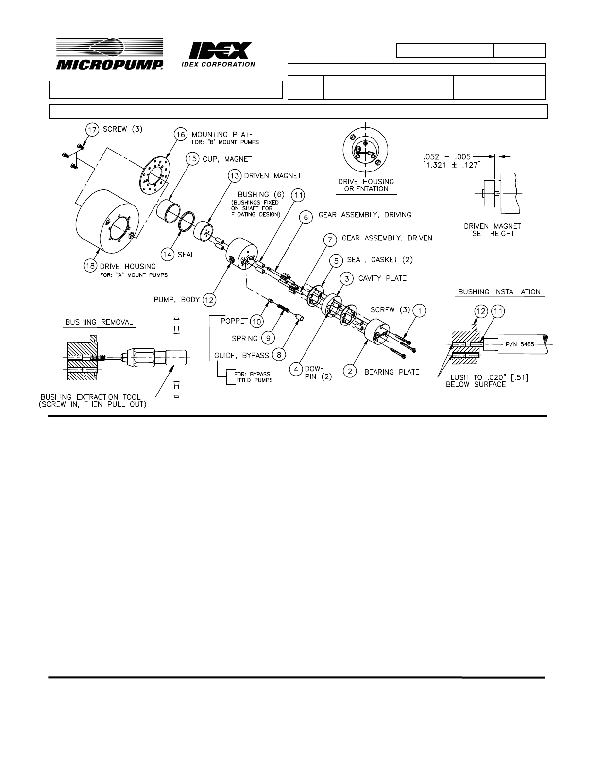
1. Remove old Bushings(11) with Extraction Tool. The use of a #8 or M4 tap with T-Handle is recommended (See
Figure 3.).
2. New Bushing installation is a press fit. Install using P/N 5465 tool. (See Figure 4.)
3. The first two Bushings should be installed into the Pump Body (12) from the gear side. These Bushings should
be inserted to .020 inch (.51mm) below seal surface. Then two bushings should be inserted into the Pump Body
from the Driven Magnet (13) side. Also, install two Bushings in the Bearing Plate (2).
4. Next install Gears (6) & (7) and Driven Magnet (13). Set Driven Magnet height from Pump Body (12) pilot, as
shown in Figure 2, using P/N 6009 Magnet Set Height Tool between Pump Body (12) and Driven Magnet (13),
press Driven Magnet (13) down until it touches the Magnet Set Height Tool.
5. Driven Magnet and Gears must rotate freely - tight Bushings may be reamed with a #30 reamer.
6. Install Parts (1) - (5) in order, then complete rest of assembly.
MICROPUMP, INC.
A Unit of IDEX Corporation
PO Box 8975, Vancouver, WA 98668-8975 • Phone: 360/253-2008 • Fax: 360/253-8294
Howard Road, Eaton Socon, St.
MICROPUMP
A Subsidiary of Micropump, Inc.
Neots, Cambridgeshire, PE 19 8ET England, • Phone: (44) (0) 1480-356600 • Fax: (44) (0) 1480-356300
LIMITED
 Loading...