

Micropump GAH Series Service Instructions
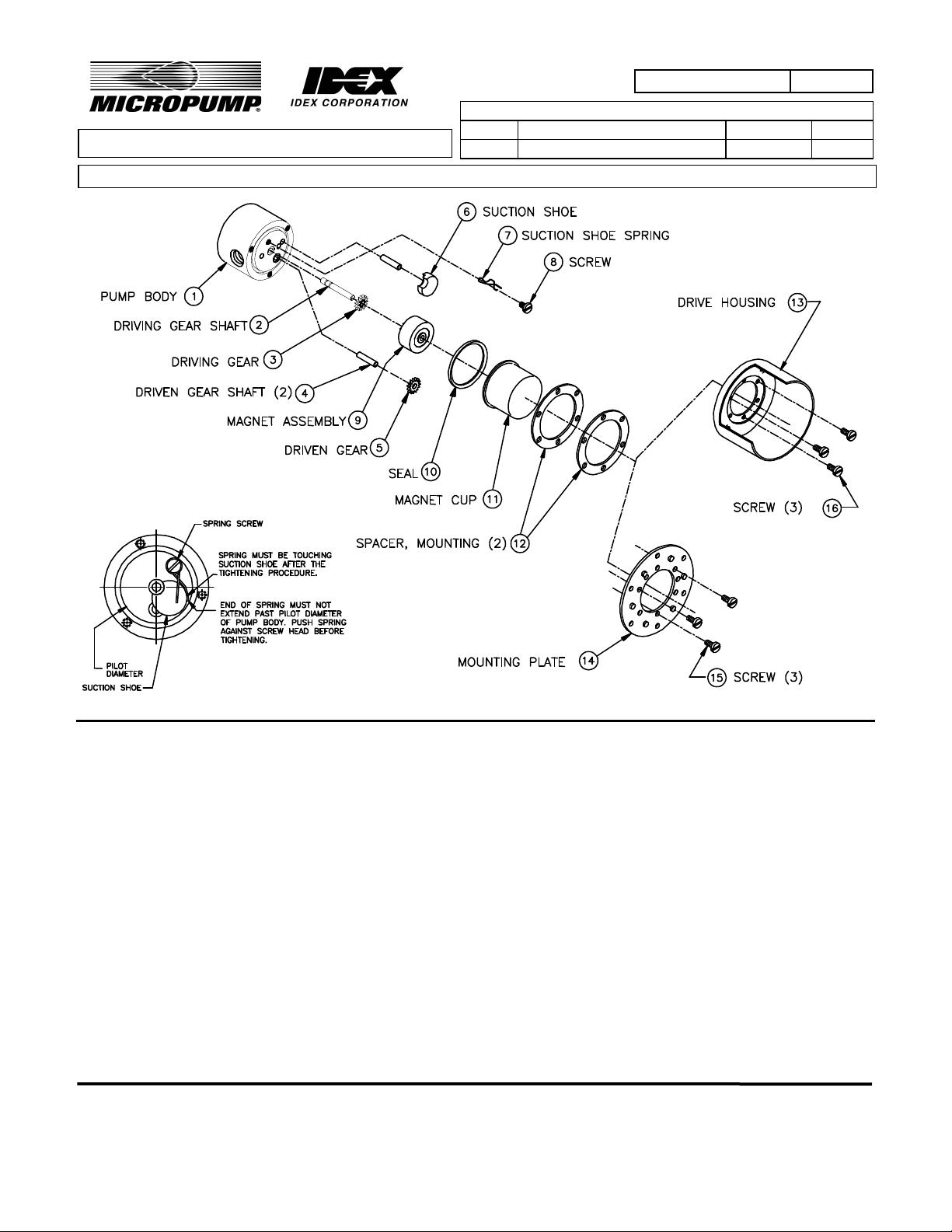
FIGURE 1
PART NUMBER: L23125
SERVICE INSTRUCTIONS: L23125
MOD: GA - 180 SERIES A & B MOUNT
LTR. DESCRIPTION DATE BY
A ORIGINATED PER E14154 15JAN04 CMA
REVISION
GENERAL:
1. All service work should be performed in a clean area.
2. Care should be taken to avoid scratching any sealing surfaces or allowing metal chips to come in contact with
the Driven Magnet Assembly.
3. An even, light coat of high vacuum silicone grease (Dow Corning or equiv.) should be applied to all seals or ORings.
4. O-Rings with chamfers should always be installed with the chamfer up, away from the groove.
5. All assembly screws should be tightened evenly and in an alternating pattern.
6. Only Micropump factory authorized replacement parts should be used when servicing any Micropump products.
SPECIFIC:
1. Do not attempt to remove Driving Gear Shaft (2) from Pump Body (1). The Shaft (2) position is preset at the
factory. (If replacement of shaft is necessary, pump must be returned to the factory for repair.)
2. After installing the Suction Shoe (6), locate the Suction Shoe Spring (7) so that it holds the Suction Shoe in
place. Then locate Screw (8) through the Spring, into the Pump Body (1)(as shown in FIGURE 1 above) and
tighten the Screw.
3. Engage drive pins on the Magnet Assembly (9) with Driving Gear (3). Gears and Magnet should rotate freely.
4. Complete assembly as shown above.
MICROPUMP, INC.
A Unit of IDEX Corporation
PO Box 8975, Vancouver, WA 98668-8975 • Phone: 360/253-2008 • Fax: 360/253-8294
Howard Road, Eaton Socon, St.
MICROPUMP
A Subsidiary of Micropump, Inc.
Neots, Cambridgeshire, PE 19 8ET England, • Phone: (44) (0) 1480-356600 • Fax: (44) (0) 1480-356300
LIMITED
 Loading...