

Page 1

MicroPulse P/N 9100-001-M
Installation and Operating Instructions
PARTS SUPPLIED 9100-001-M:
1 ea MicroPulse Control P/N 9100-001-M, including Installation Instructions
4 ea Fully Insulated Blue Female #6 Crimp on Ring Lug Connectors for 14-16 AWG Wire.
4 ea 6-32 X 1/4 Button Head Socket SS screws including #6 SS Internal Lock Washer
1 ea 1/16 in Long Handle Key Allen Wrench
1 ea 5/64 in Long Handle Key Allen Wrench
2 ea Reference Sticky Back Panel label, 1 black background, 1 clear
1 ea knob, drill guide for bushing/anti-rotation pin, various mounting hardware
NEW INSTALLATION: CAUTION-REVERSE WIRING OF POWER TO DEVICE WILL DAMAGE IT.
1. Locate a convenient place for the MicroPulse Control. Using the drill template, mark the 9mm and
2.1mm hole locations. Drill a 9MM hole and 2.1mm hole (if using anti-rotation pin) at the location
where the marks indicate..
2. Determine the total current that the circuit will be required to carry.
3. Test Position the MicroPulse Control and determine if any additional wire is required.
4. Remove the MicroPulse Control and proceed with the installation. From the WIRE SIZE-CURRENT CA-
PACITY TABLE, select the wire size required. If the installation is in an Aircraft, use only MIL-W-
16878E/4 Type E, Teflon insulated, Silver-Plated Copper Wire or equivalent.
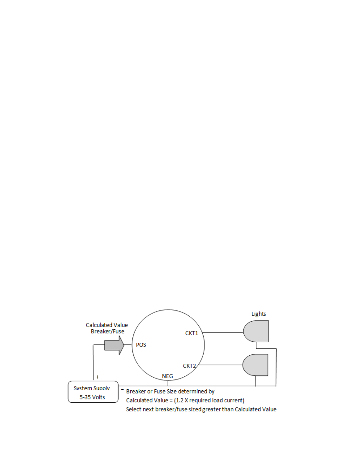
5. Install a breaker of ’Calculated Size’, see Wiring Diagram for sizing.
6. Run a wire from the Breaker to the MicroPulse controller positive (POS) terminal, then select and
crimp Blue Female Solderless Ring Lug Connector on the end of the wire. Attach the ring connector
onto the positive connector on the MicroPulse controller using a washer and a SS screw .
7. Using the same technique that was used in section #7, run a wire from the GND ring terminal on the
MicroPulse to system ground. The common (Gnd) Wire is simply a signal wire used by the unit. It
does not carry heavy currents during operation. Use a Blue Female Solderless Ring Lug Connector
for this wire.
8. Again using the same technique that was used in section #7, run a wire from the output CKT on the
dimming circuit. Select and crimp on a Blue Crimp on ring Connector the end of the wire. Attach
the ring connector onto the connection the MicroPulse controller using a washer and a Button Head
Socket SS screw.
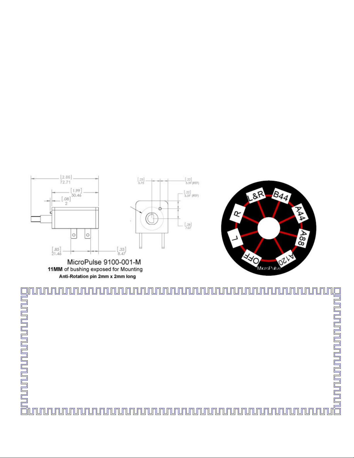
9. With the MicroPulse Control inserted from the rear into the 9MM drilled hole and with the reference
label placed over the threads on the MicroPulse Control, install a washer and a nut to hold the MicroPulse Control in place. Insure that the placard is vertically aligned. Best to use ‘hinge method’ of
alignment of the placard.
10. Install the knob using the Long Handle Key Allen Wrench provided.
EXISTING/REPLACEMENT INSTALLATION:
1. Locate a convenient place for the MicroPulse Control. Using the drill template, drill a 9MM and
2.1mm hole at the location where the center of the MicroPulse is desired. Determine the Positive
supply, MicroPulse circuits, and negative ground wiring.
Document 9150-017-A
Pg 1 of 3 Rev A 10/4/12
Page 2
2. Test Position the MicroPulse Control and determine if any additional wire is required for the installa-
tion.
3. Insure that a breaker for the MicroPulse Controller power source is installed in series with power
source and sized to ‘Calculated Value’ as defined on the wiring diagram.
4. Remove the MicroPulse Control and proceed with the installation. From the wire size-current capacity table, select the wire size required if additional wire is required. If the installation is in an Aircraft,
use only MIL-W-16878E/4 Type E, Teflon insulated, Silver-Plated Copper Wire or equivalent.
5. Run a wire from the Breaker to the MicroPulse controller positive (POS) terminal, then Select and
install a Blue Female Solderless Ring Lug Connector on the end of the wire. Attach this to the POS
connector on the MicroPulse controller.
6. Using the same technique that was used in #5, run a wire from the male connector terminal on the
MicroPulse to system ground. The common (Gnd) wire is simply a signal wire used by the unit. It
does not carry heavy currents during operation. Use a Blue Solderless Ring Lug Connector for this
wire. Connect to GND connector of device.
7. Again using the same technique that was used in #5, run wire from output CKT for the device circuit.
Select and install a Blue Solderless Ring Lug Connector on the end of the wire and connect it onto
the male connector on the MaxDim Controller.
8. With the MicroPulse Control inserted from the rear into the 9MM drilled hole and with the reference
label placed over the threads on the MicroPulse Control, install a washer and a nut to hold the Micro
Pulse in place.
9. Install the knobs using the 1/16’ long handle key Allen wrench provided.
FUNCTIONAL TEST:
1. Turn knob fully counter clockwise and apply power to the system.
2. Slowly rotate each knob clockwise. The MicroPulse Circuit will activate and track the indicator on
the placard. CKT1 is ‘L” on placard.
Wiring Diagram 9100-001-M MicroPulse
MicroPulse
Document 9150-017-A
Pg 2 of 3 Rev A 10/4/12
Page 3
Voltage Range: 5 to 35VDC
—SPECIFICATIONS—
Operating Temperature range: -30°C to +65°C
Max Current: 8A / CKT
Controlled Output: 0 to 5/35 VDC
0 to 8.0A Per Circuit
Capacity per CKT
40 Watts @ 5 VDC
96 Watts @12 VDC
192 Watts @ 24 VDC
224 Watts @ 28 VDC
Potentiometer Rotation: 300 Deg.
Internal Temperature Protect: +85°C
Storage Temperature: -40°C to +100°C
Maximum Internal Temperature: @ 8A
+5 °C above Ambient.
Enclosure Material: Avantra 8731
Meets UL 94-0 @ .062”/1.5mm min.
DO-160E, EMI
Order P/N 9100-001-M
Rotational Life: 500KTurns
ONE YEAR LIMITED WARRANTY
MPMD will repair or replace, at its expense and at its option any device manufactured by MPMD
which in the normal use has proven to be defective in workmanship or material, provided that the
customer returns the product prepaid to MPMD along with proof of purchase of the product within
one year and provides MPMD with reasonable opportunity to verify the alleged defect by inspection.
MPMD will not be responsible for any asserted defect which has resulted from misuse, abuse or over
stressing above the published specifications. MPMD will under no circumstances be liable for incidental or consequential damages resulting from the defective products. This warranty is MPMD’s
Sole warranty and sets forth the customer’s exclusive remedy, with respect to defective products; all
other warranties, express or implied, whether of merchantability, fitness for purpose, or otherwise,
are expressly disclaimed by MPMD.
MaxPulse MaxDim, Statesboro, GA
Document 9150-017-A
Pg 3 of 3 Rev A 10/4/12
 Loading...