

Page 1

________________________________________________________________________________
LOGIJET T8-3
Operator’s Manual
Edition 1.0prel
________________________________________________________________________________
Page 2

2
_______________________________________________________________________________________________
Protected Rights
In MICROPLEX documentations (Operator’s Manuals, Service Manuals etc.) product names are
generally given without any mention of existing patents, registered designs or trademarks. The
absence of a corresponding remark does not give any implication that the name can be used at
will. All trademarks are recognised as protected.
Alterations
No liability is assumed for the accuracy of the contents of the documentations. MICROPLEX
reserves the right to alter technical or other specifications with no prior notice. Deviations in the
documentations from prevailing conditions do not represent an obligation to redeliver.
Product Properties
Due to continuous updating of the products deviations between the documentations and the
relating product can occur.
The manufacturer does not guarantee the existence or non-existence of properties with the
description of subject contents in the documentations. Nor does the manufacturer give any express
or tacit guarantee declarations whatsoever.
_______________________________________________________________________________________________
MICROPLEX Operator’s Manual LOGIJET T8-3 Edition 1.0prel
Page 3

Contents 3
_______________________________________________________________________________________________
Table of Contents
Chapter Page
1. Introduction 7
1.1. General Description 7
1.2. Fundamentals of Thermal Printing 8
1.3. Conventions 9
1.4. General Safety Regulations 11
2. Installation 15
2.1. Printer Unpacking 15
2.2. Check List 17
2.3. Printer Installation 18
2.4. Printer Components 19
3. Basic Operation Sequences 23
3.1. Overview 23
4. Handling of Consumables 25
4.1. Winding Diagram 26
4.2. Handling of Ribbon (Foil) 27
4.2.1. Ribbon Loading 27
4.2.2. Ribbon Removal 36
4.3. Roll-Fed Media Handling 37
4.3.1. Roll-fed Media Loading 37
4.3.2. Media Removal 46
4.4. Printhead Pressure Adjusting 47
_______________________________________________________________________________________________
MICROPLEX Operator’s Manual LOGIJET T8-3 Edition 1.0prel
Page 4

4 Contents
_______________________________________________________________________________________________
Chapter Page
5. Operation and Menu Structure 51
5.1. Attaching the Printer to a Network/PC 51
5.2. Turning on the Printer 52
5.3. Control Panel View 53
5.4. Function of the Control Panel Elements 54
5.5. Configuration via the Control Panel 56
5.6. Menu Structure 58
5.7. Syntax of Diagrams 63
6. Panel Functions 64
6.1. Selecting and Adjusting the Sync Sensors 64
6.1.1. Selecting the Light Sensor Type (Gap or Reflex) 65
6.1.2. Checking and Adjusting the Sensors 66
6.1.3. Automatic Adjust of Sensor Current and Switching Threshold 68
6.1.3.1. Overview 68
6.1.3.2. Example 69
6.1.4. Manual Adjusting of Sensor Current and Switching Threshold 70
6.1.4.1. Reflex Sensor (Black Mark Sensor) 71
6.1.4.2. Gap Sensor (Transparent Sensor) 73
6.1.4.3. Example: Determining the Switching Threshold for a Label Material 75
6.2. Print Process Selecting 78
6.3. Ribbon Unwinding Setting (Ink Inside or Outside) 80
6.4. Media Setting (Material; Label or Continuous) 81
6.5. Adjusting the Zero Position of the Material Transport (Sync.Sens.Offset) ) 82
6.6. Page Length Adjustment 84
6.6.1. Starting the (Printer’s) Measurement of Label Length 86
6.6.2. Configuration of Semiautomatic Label Length Measurement 86
6.7. Material Width Adjustment (Paper Width) 87
6.8. Configuration of Text Margins 89
6.9. Printing the Status Sheet 90
6.10. Printing the Font List 92
6.11. Hexdump Mode Activation 93
6.12. Normal Print Mode Activation (incl. FORM FEED) 94
6.13. Clearing the Input Buffer (Cancel Job) 95
_______________________________________________________________________________________________
MICROPLEX Operator’s Manual LOGIJET T8-3 Edition 1.0prel
Page 5

Contents 5
_______________________________________________________________________________________________
Chapter Page
6.14. Printing the Menu Page 96
6.15. Generating Testsheets (Sliding Pattern) 97
6.16. Print Direction Selection 98
6.17. Data Interface Configuration 99
6.18. Emulation Selection 100
6.19. Display Language Selection 102
6.20. Transparent Code Adjustment 103
6.21. Selection of Memory Distribution (Input Buffer) 104
6.22. Setting to Factory Default 105
6.23. Font Selection 106
6.24. Text Orientation Selection 109
6.25. Symbol Code Selection 110
6.26. Lines per Inch Setting (Line Spacing) 111
6.27. Number of Characters per Inch Setting (Character Spacing) 112
6.28. Print Speed Adjustment 113
6.29. Density (Contrast) Setting 114
6.30. Image Shifting to the X-Direction 115
6.31. Image Shifting to the Y-Direction 117
6.32. Peripheral Device Activation (Tear Off Edge, Cutter) 119
6.33. Selecting the Tear Off Mode (Option: Cutting Mode) 122
6.34. Adjusting the Tear Off Position (Option: Cutting Position) 124
6.35. Selecting the Print Mode 126
6.36. Configuration of Network Parameters (IP Address, e.g.) 129
7. Operator Maintenance 133
7.1. Printer Cleaning 133
7.1.1. Printer Cabinet Cleaning 134
7.1.2. Printhead Cleaning 135
7.1.3. Platen Roller Cleaning 138
7.2. Adjusting the Right Pressure Value 139
_______________________________________________________________________________________________
MICROPLEX Operator’s Manual LOGIJET T8-3 Edition 1.0prel
Page 6

6 Contents
_______________________________________________________________________________________________
Chapter Page
8. Troubleshooting 140
8.1. Printer Error Messages 141
8.2. Reduced Print Quality 145
8.3. Incorrect Media Transport 147
8.4. Print Repetition after an Error 149
9. Measures for Transport and Shipping (Repacking) 151
10. Specifications 153
11. Index 157
_______________________________________________________________________________________________
MICROPLEX Operator’s Manual LOGIJET T8-3 Edition 1.0prel
Page 7

Introduction 7
_______________________________________________________________________________________________
1. Introduction
1.1. General Description
The LOGIJET T8-3 is a multifunctional non-impact printer based on
thermal print technology.
The device can be used for thermal transfer printing as well as for
thermal direct printing. Because of its wide range of application, you
can use it to print all kind of information as barcodes, alphanumerical
characters and vector graphics e.g. .
This printer not only knows one device-specific page description
language as standard thermal printers usually do, but most of the
languages used in the industrial field and the well-known market
standards of laserprinters, too.
For this printer options are available (for example, cutter).
The LOGIJET T8-3 printer is provided with a controller that is also
used in SOLID laserprinters. So the advantages of the thermal print
technology are combined with the flexibility of the „laserprinter
intelligence“.
The MICROPLEX printer controller has its integrated website, this
allows a printer configuration via Ethernet. See Networking
Features of MICROPLEX Printers for more information.
Data can be sent without programming expenditure from almost
any software platform, because printer drivers are already
available for this.
The capabilities featured include the MICROPLEX page description
language IDOL. Using this language, complex tasks such as the
creation of forms can be carried out by simple software commands
(see separate IDOL manual).
The resolution is 300 dots per inch corresponding to about 12 dots
per mm.
The print speed is up to 6 inch/second (up to 150mm/second).
Roll-fed media as well as continuous-media can be printed on.
The maximum processable width of media for the LOGIJET T8-3 is
241.3mm (9.5”). 219.5mm (8.64”) of that are printable.
_______________________________________________________________________________________________
MICROPLEX Operator’s Manual LOGIJET T8-3 Edition 1.0prel
Page 8

8 Introduction
_______________________________________________________________________________________________
1.2. Fundamentals of Thermal Printing
The thermal print technology enables a quiet and fast print process with a
high resolution output. The printhead produces the image by heating
single elements (dots). So you need a special ribbon (thermal transfer
printing) or a special kind of paper (thermal direct printing).
While thermal transfer printing the dots touch the thermal ribbon so that
the heating of particular dots leads to a partial melting of the ribbon. Due
to the contact with a media (future carrier of the information, for example
paper) this leads to a transfer of the image onto the media.
While thermal direct printing the dots touch the thermal paper directly.
The dyes and developers within the paper respond to the heat of
particular dots, change their colour to black and so the wanted image
emerges.
The printer LOGIJET T8-3 can be used for both methods of printing.
_______________________________________________________________________________________________
MICROPLEX Operator’s Manual LOGIJET T8-3 Edition 1.0prel
Page 9
Introduction 9
blue colored text
[Menu Level 1 ]
To find the requested information more quickly and to
understand instructions more easily, the following conventions
are used:
This symbol refers to a possible source of danger. If you do not
pay attention to this information, injuries may result, the function
of the printer could be reduced or objects could be damaged.
This symbol refers to important hints and suggestions on using
the printer. Disregarding these hints might cause problems with
the printer or within the environments.
This symbol shows a key of the control panel. Such symbols will
be used in this manual whenever keys have to be pressed in
order to activate certain functions.
Link to another chapter or a different document. By clicking the
blue colored text you'll enter the concerning chapter or
document.
This symbol represents messages shown in the display (panel).
_______________________________________________________________________________________________
1.3. Conventions
_______________________________________________________________________________________________
MICROPLEX Operator’s Manual LOGIJET T8-3 Edition 1.0prel
Page 10

10 Introduction
_______________________________________________________________________________________________
_______________________________________________________________________________________________
MICROPLEX Operator’s Manual LOGIJET T8-3 Edition 1.0prel
Page 11
Introduction 11
This device produces, employs and possibly radiates high
frequency energy. Because of this, incorrect installation can
disturb radio communications.
This MICROPLEX product and its consumables are designed and
tested according to strict safety standards.
Heeding the following instructions ensures secure operation:
- Please make sure your electricity source is appropriately
grounded.
- Install the device on solid and level ground.
- Only trained staff are authorized to transport the equipment.
_______________________________________________________________________________________________
1.4. General Safety Regulations
_______________________________________________________________________________________________
MICROPLEX Operator’s Manual LOGIJET T8-3 Edition 1.0prel
Page 12
12 Introduction
- Only use consumables which are specially developed for this
device.
- Using unsuitable consumables may cause a reduction of output
quality or damages to the device.
- Ensure no liquids get on or into the device.
- Do not remove any cover or safety device fastened by screws.
- Do not remove or bridge over any safety device.
- Do not push anything into the ventilation apertures.
- Never carry out installations, cleanings or maintenance
operations which are not described in this manual. This should
only be done by MICROPLEX authorized service personnel.
_______________________________________________________________________________________________
_______________________________________________________________________________________________
MICROPLEX Operator’s Manual LOGIJET T8-3 Edition 1.0prel
Page 13

Introduction 13
- Be careful when operating equipment with opened cover
hoods (setting-up work or service). Rotating parts can cause
injury , and it is also possible for hair, clothing, jewellery,
etc. to be caught in the machinery.
Ribbon and material should only be inserted and changed by
specially instructed personnel.
- Optional device components may only be installed by
authorized personnel, and in accordance with the
appropriate assembly and usage regulations.
- The cutter may only be installed by trained personnel.
- Only attach or remove the printhead when the device is
switched off.
After switching off the device, wait at least 3 minutes before
removing the printhead.
- Only plug in or remove interface connectors when the device
is switched off.
_______________________________________________________________________________________________
_______________________________________________________________________________________________
MICROPLEX Operator’s Manual LOGIJET T8-3 Edition 1.0prel
Page 14
14 Introduction
In order to disconnect the printer quickly from the main power
in case of emergency please note the following:
- For connected printers with plugs, the power-outlet should
be installed near the printer and easily within reach.
- For permanently connected printers, an easily accessible
emergency power-off switch should be installed close to the
printer.
- Please do not conceal any disconnect devices with the
printer or other objects.
- After switching off the device, wait at least 15 seconds
before the device is switched on again.
- Please follow all the information and hints directly attached
to the device and/or described in this manual.
_______________________________________________________________________________________________
_______________________________________________________________________________________________
MICROPLEX Operator’s Manual LOGIJET T8-3 Edition 1.0prel
Page 15
Installation 15
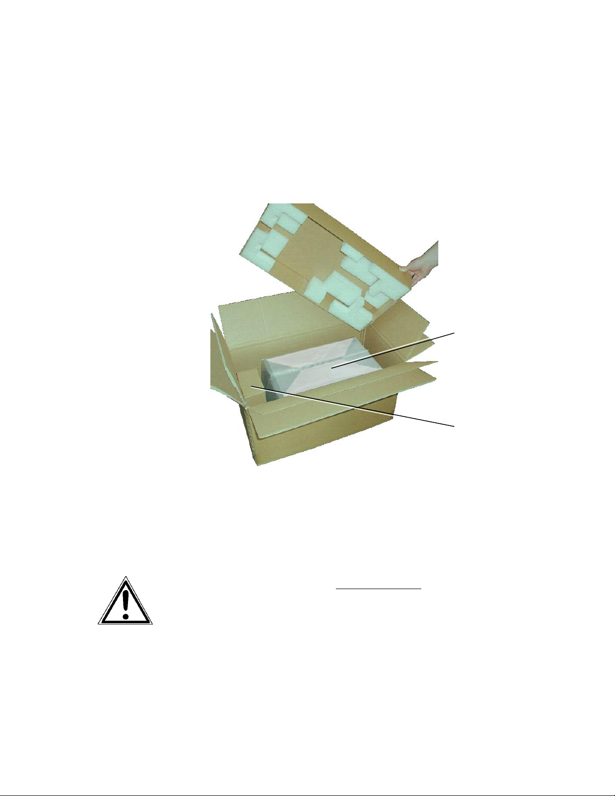
Take hold of the printer from the bottom.
Do not use other parts of the printer (e.g. plastic parts at the
printer's front or rear side ...) to lift the device!
Box contains
accessories
Printer
_______________________________________________________________________________________________
2. Installation
2.1. Printer Unpacking
1. Open the box and remove the accessory parts.
Hint: The shipping box etc. of your printer may differ in
form and optic from the parts shown in the
following 2 figures.
Fig. 2.1.a Printer in the shipping box
2. Take the printer and lift it out the box carefully. Get
somebody to hold the box when removing the printer.
_______________________________________________________________________________________________
MICROPLEX Operator’s Manual LOGIJET T8-3 Edition 1.0prel
Page 16

16 Installation
_______________________________________________________________________________________________
Fig. 2.1.b Lifting the printer
3. Remove the foil covering the printer.
4. Place the printer onto a suitable base (see section 2.3).
Please retain the original packing materials in case the printer
has to be transported in the future.
_______________________________________________________________________________________________
MICROPLEX Operator’s Manual LOGIJET T8-3 Edition 1.0prel
Page 17
Installation 17
_______________________________________________________________________________________________
2.2. Check List
First of all place the printer and the accessories onto a level
surface until the definitive location is chosen.
Please make sure that all items are included and that there are
no defects.
Immediately inform your supplier of any damage.
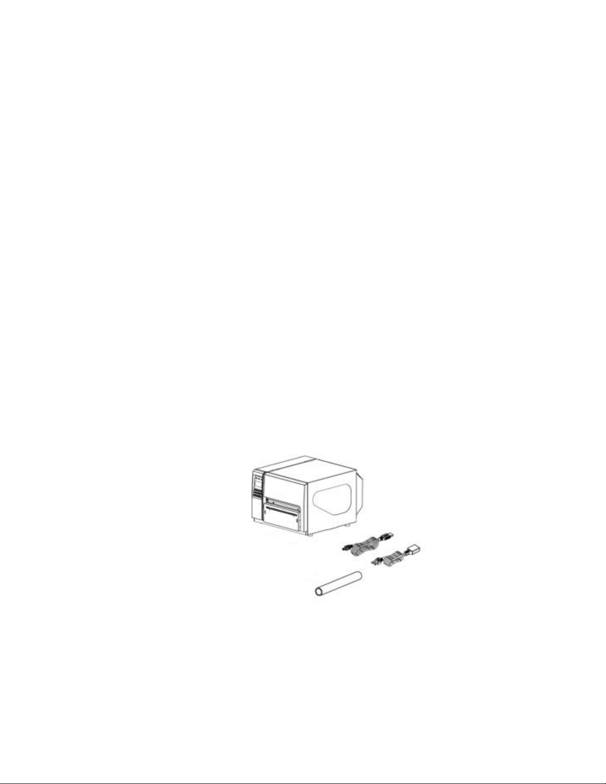
Open the cardboard box carefully and check the contents:
1. Printer LOGIJET T8-3
2. Power cord
3. Data cable (USB)
4. empty Ribbon Sleeve (Ribbon Core)
5. CD containing:
Operator’s Manual for LOGIJET T8-3
Print drivers
IDOL Programming Manual
Fig. 2.2.a Printer with accessories
_______________________________________________________________________________________________
MICROPLEX Operator’s Manual LOGIJET T8-3 Edition 1.0prel
Page 18
18 Installation
- The chosen location should be well-ventilated, clean and dry.
- Damaging environmental factors such as metal vapors, oil mist,
corroding lixivium or the like must not come into contact with
the printer.
- Position the printer on solid and level ground.
- Do not exposure the printer to shocks or vibrations.
- The printer and socket have to be easily accessible.
- The printer should not be located near volatile or combustible
materials (e.g. a curtain).
- The printer must be connected to an appropriate AC power
source 120V AC/60 Hz (North America) or 230V/50 Hz
(Europe, United Kingdom e.g.). The power source must be
properly grounded. The socket and power cords must not be
damaged.
- Use the printer only within the allowed fluctuation range of
±10%.
- The voltage support must not be impaired by interference.
- In order to run the printer reliably, please maintain the
following environmental conditions:
Temperature: +5°C to +40°C (operating)
-40°C to +60°C (storage temperature)
Relative atmospheric humidity: 20% to 85% (without
condensation)
- Do not expose the printer to abrupt temperature changes
(heating, window or air condition).
- The printer should not be exposed to direct sunlight.
_______________________________________________________________________________________________
2.3. Printer Installation
_______________________________________________________________________________________________
MICROPLEX Operator’s Manual LOGIJET T8-3 Edition 1.0prel
Page 19
Installation 19
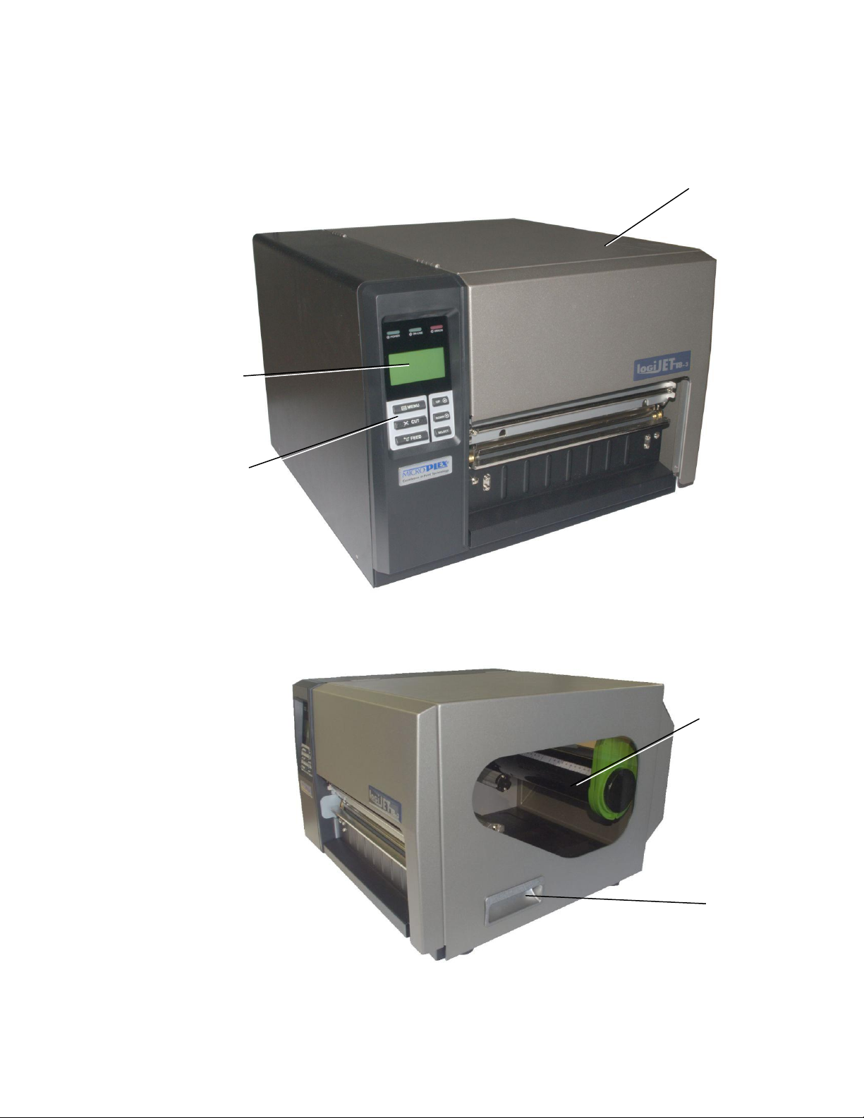
Window
Check the material / foil
supply without opening
the cover.
Cover
Open to insert material
and foil.
LCD Display
Control Panel
6 keys; displays printer
operation status, enables
settings via the menu.
Handle to
open the
cover
_______________________________________________________________________________________________
2.4. Printer Components
Main view:
_______________________________________________________________________________________________
MICROPLEX Operator’s Manual LOGIJET T8-3 Edition 1.0prel
Fig. 2.4.a Main view of the printer LOGIJET T8-3
Fig. 2.4.b Side view of the printer
Page 20
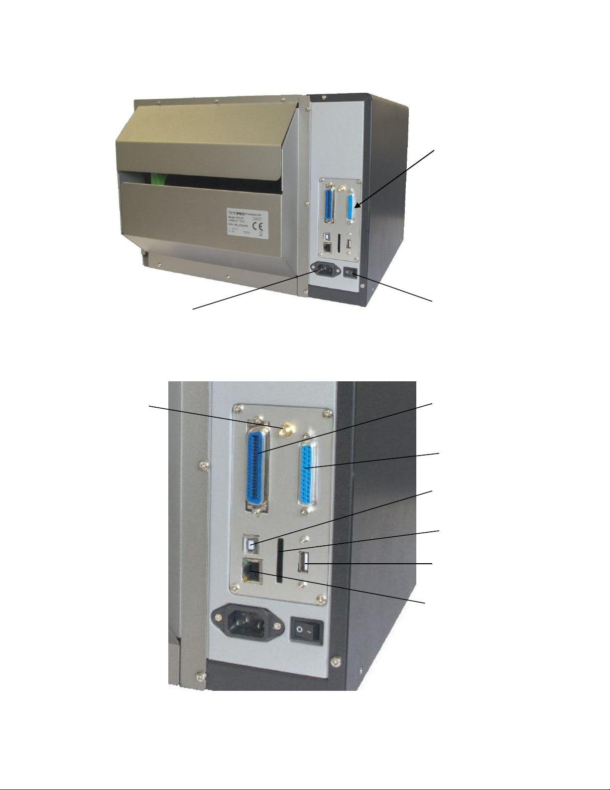
20 Installation
Interfaces
Power socket
Power switch
RS232/RS422
(Optional)
Network interface
(Ethernet)
IEEE 1284
(Centronics)
Slot for optional
SD cards
USB Device Port
Connector for
the optional
WLAN –
Antenna
USB Host Port
_______________________________________________________________________________________________
Fig. 2.4.c Rear view of the printer
_______________________________________________________________________________________________
MICROPLEX Operator’s Manual LOGIJET T8-3 Edition 1.0prel
Fig. 2.4.d Detail: Interfaces of the LOGIJET T8-3
Page 21
Installation 21
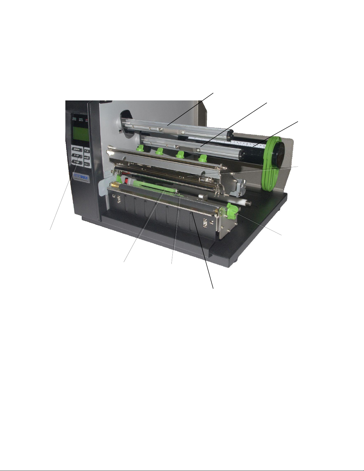
Printhead release
lever
Gap Sensor Reflex Sensor
(GAP) (Blackmark)
(Material/Media Sensors; green)
Printhead
Control
panel
Ribbon rewind
spindle
Ribbon supply
spindle
Media supply
spindle
Tear off edge
_______________________________________________________________________________________________
_______________________________________________________________________________________________
MICROPLEX Operator’s Manual LOGIJET T8-3 Edition 1.0prel
Fig. 2.4.e Inside View of the printer
Page 22

22 Installation
_______________________________________________________________________________________________
_______________________________________________________________________________________________
MICROPLEX Operator’s Manual LOGIJET T8-3 Edition 1.0prel
Page 23
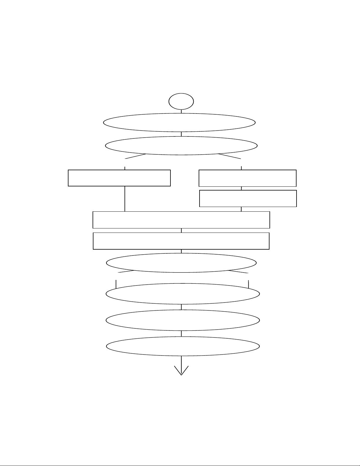
Basic Operation Sequences 23
print process selecting
thermal transfer
media loading
media (material) setting
label
continuous
page length /paper width setting
margin setting
see chapter 6
see chapter 4
see chapter 6
see chapter 6
see chapter 6
start
printhead pressure adjusting
see chapter 4
selecting and adjusting the Sync sensors
see chapter 6
ribbon removal
ribbon loading
see chapter 4
see chapter 4
thermal direct
ribbon unwinding setting
see chapter 6
material transport zero position adjusting
see chapter 6
_______________________________________________________________________________________________
3. Basic Operation Sequences
3.1. Overview
_______________________________________________________________________________________________
MICROPLEX Operator’s Manual LOGIJET T8-3 Edition 1.0prel
Page 24

24 Basic Operation Sequences
If the panel settings above shall be effective permanently (that
means they do not have to be put in again after a printer
OFF/ON) the setting values can be saved permanently by
operating the ENTER key two times.
An output of the current setting values can be generated using the
"Printing the Status Sheet“ panel function (see section 6.9).
Detailed information on the operations above and to further
functions of the printer LOGIJET T8-3 can be found in the
following chapters.
_______________________________________________________________________________________________
_______________________________________________________________________________________________
MICROPLEX Operator’s Manual LOGIJET T8-3 Edition 1.0prel
Page 25
Handling of Consumables 25
Pay attention to the following safety instructions and the instructions
listed in section 1.5, too!
Safety instructions:
- The cutter (optional device of your printer) can cause injuries if the
printer is operated incorrectly.
- There is a danger of fingers, hair, clothing, jewellery etc. being
drawn into the machine in the vicinity of the material transport unit.
- Be careful when operating equipment with opened cover hoods
(setting-up work or service). Rotating parts can cause injury, and it
is possible for hair, clothing, jewellery, etc. to be caught in the
machinery.
- Print material should only be inserted and changed by specially
instructed personnel.
For thermal direct printing it is not allowed to load a ribbon to avoid
damaging the printhead. Make sure your settings using the control
panel and display respectively via interface (see chapter 5 and 6) fit
to the printer implementation (ribbon inserted /not inserted).
Ribbon and material should only be inserted/exchanged by specially
instructed personnel.
_______________________________________________________________________________________________
4. Handling of Consumables
_______________________________________________________________________________________________
MICROPLEX Operator’s Manual LOGIJET T8-3 Edition 1.0prel
Page 26
26 Handling of Consumables
Ribbon roll
Printhead
release lever
Material roll
(Label)
Printhead
unit
(2 moveable sensors:
Gap and Blackmark)
_______________________________________________________________________________________________
4.1. Winding Diagram
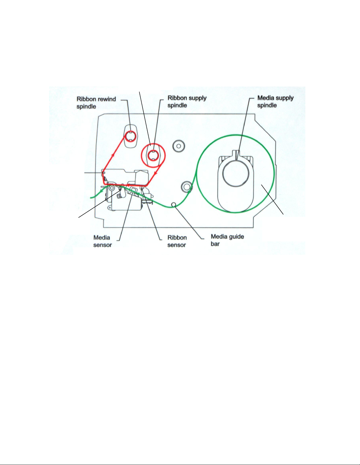
Fig. 4.1.a Winding directions of material and ribbon (here: ink outside the roll)
The diagram above shows the usual winding directions of material and
ribbon.
Pay attention to the different ribbon roll winding directions described in
section 4.2.1 Ribbon Loading. The figure above shows the winding
directions for “Ink outside the roll” ribbons. Also pay attention to the
instructions located on the inside of the printer hood.
_______________________________________________________________________________________________
MICROPLEX Operator’s Manual LOGIJET T8-3 Edition 1.0prel
Page 27
Handling of Consumables 27
Make sure you always use a printer ribbon being wider than the
media to print on. In the case of printing on abrasive media
printhead damaging can be avoided this way.
_______________________________________________________________________________________________
4.2. Handling of Ribbon (Foil)
4.2.1. Ribbon Loading
If you want to operate the printer in the thermal transfer mode a
printer ribbon has to be used (compare section 1.1).
To set the ribbon go on like this:
1. Switch the printer to OFF LINE mode.
2. Open the printer hood completely.
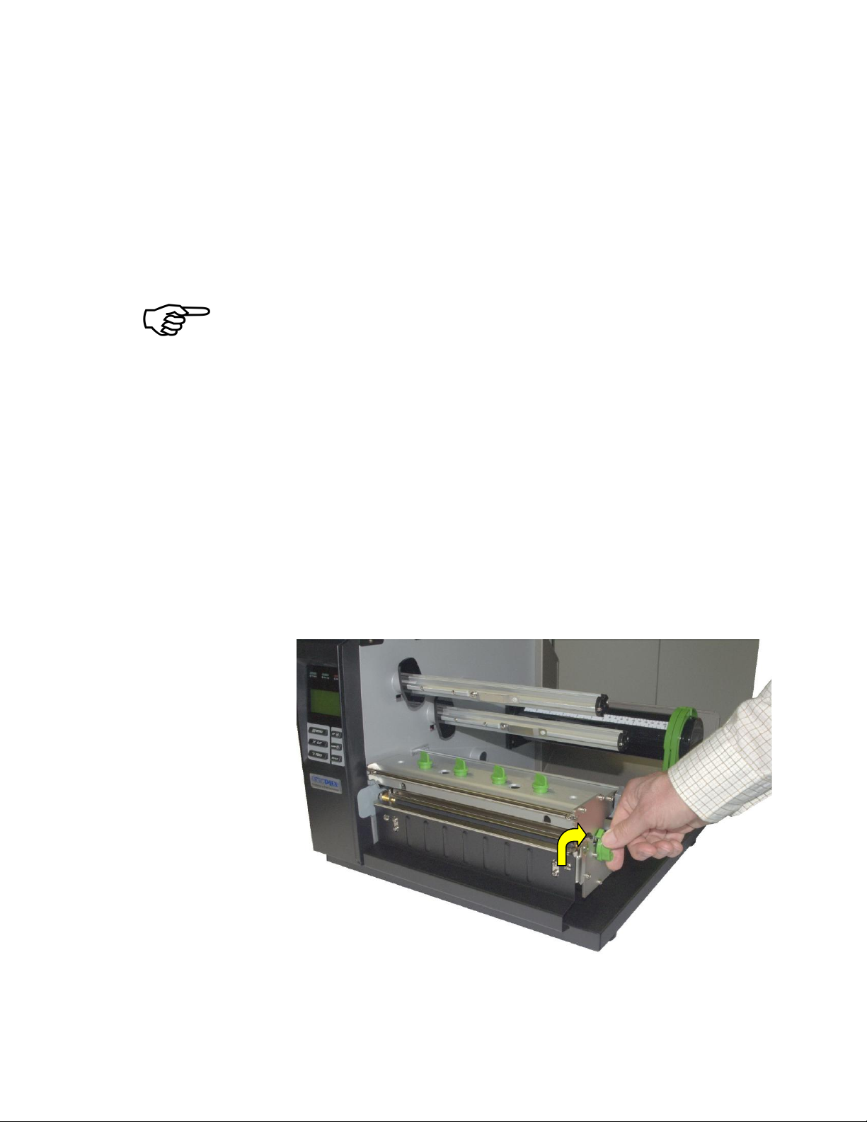
3. Push the printhead release lever clockwise to open the print
head mechanism.
Fig. 4.2.1.a Pushing the printhead release lever clockwise
_______________________________________________________________________________________________
MICROPLEX Operator’s Manual LOGIJET T8-3 Edition 1.0prel
Page 28
28 Handling of Consumables
Ribbon outside
(Ink outside the roll).
Ribbon inside
(Ink inside the roll).
Printhead mechanism
opened
_______________________________________________________________________________________________
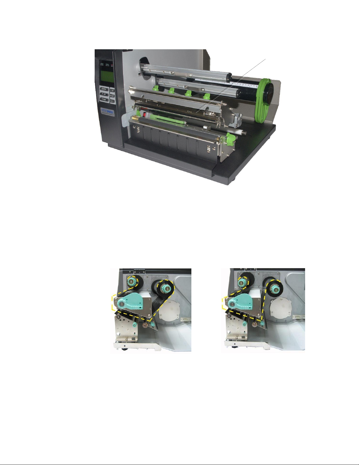
Fig. 4.2.1.b Printer with opened (released) printhead
4. Take the ribbon roll and remove the protection foil, if
necessary (by unwinding it and cutting it off).
5. Find out the right winding direction for your ribbon roll:
_______________________________________________________________________________________________
MICROPLEX Operator’s Manual LOGIJET T8-3 Edition 1.0prel
Fig. 4.2.1.c Schematic figures: Different ribbon roll winding directions
6. Use the appropriate panel function to adjust the printer to the
current winding direction.
See section 6.3 Ribbon Unwinding Setting (Ink Inside or
Outside).
Page 29
Handling of Consumables 29
Scale on the
Ribbon rewind spindle
Adjusting the empty
ribbon sleve on the
printer´s ribbon
rewind spindle
_______________________________________________________________________________________________
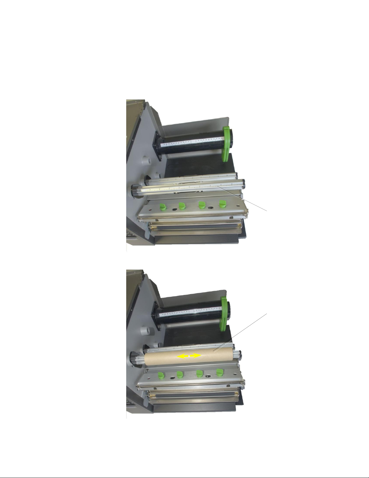
7. Slide the empty ribbon sleeve (ribbon core; extent of supply)
onto the ribbon rewind spindle.
Please note: The ribbon sleeve has to be mounted centered,
use the scale on the rewind spindle for this operation.
Fig. 4.2.1.d Scales are located on the printers supply spindle
Fig. 4.2.1.e Empty ribbon sleeve mounted centered
_______________________________________________________________________________________________
MICROPLEX Operator’s Manual LOGIJET T8-3 Edition 1.0prel
Page 30
30 Handling of Consumables
Ribbon roll
mounted to the
ribbon supply spindle
_______________________________________________________________________________________________
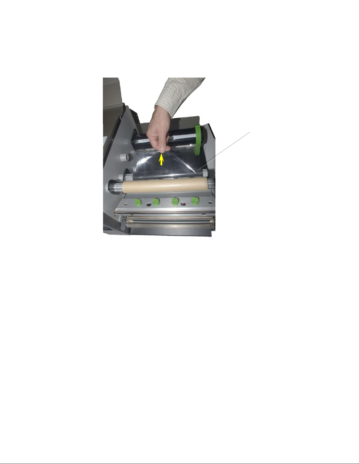
8. Slide the ribbon roll onto the ribbon supply spindle.
(Please note: it has to be mounted centered; compare step 6)
Fig. 4.2.1.f Ribbon roll mounted centered and endof foil already peeled of
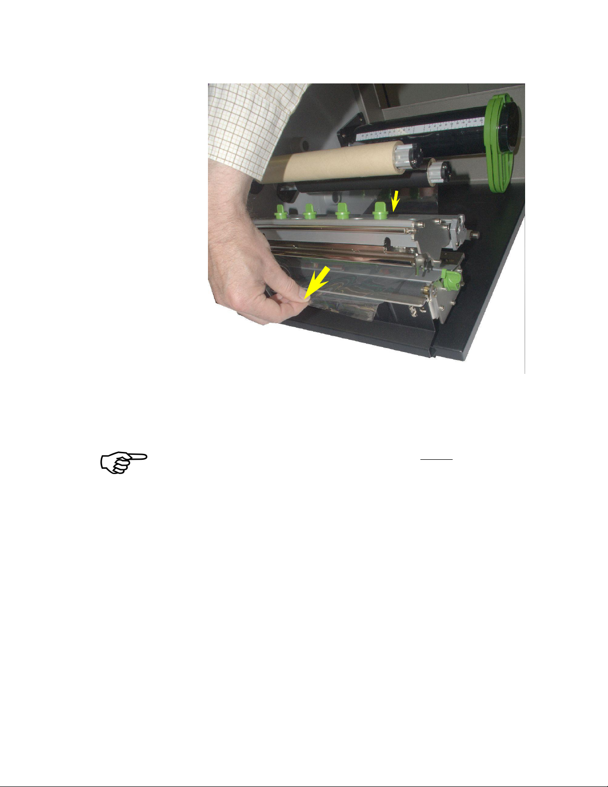
9. Route the ribbon around the printhead without folds.
_______________________________________________________________________________________________
MICROPLEX Operator’s Manual LOGIJET T8-3 Edition 1.0prel
Page 31
Handling of Consumables 31
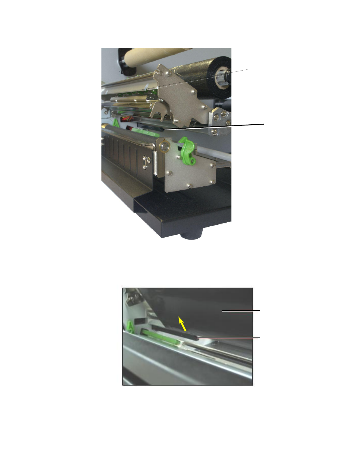
Please note: the ribbon has to be routed above the ribbon sensor
(see the black part in the following figures).
_______________________________________________________________________________________________
Fig. 4.2.1.g Foil already routed below the printhead
_______________________________________________________________________________________________
MICROPLEX Operator’s Manual LOGIJET T8-3 Edition 1.0prel
Page 32
32 Handling of Consumables
Fig. 4.2.1.h Location of the ribbon sensor inside the printer
(here still without ribbon)
Ribbon sensor
Ribbon sensor
Ribbon
Printhead mechanism
opened
_______________________________________________________________________________________________
Fig. 4.2.1.i Ribbon routed through the ribbon sensor slot
_______________________________________________________________________________________________
MICROPLEX Operator’s Manual LOGIJET T8-3 Edition 1.0prel
in the right way
Page 33
Handling of Consumables 33
Make sure that the ribbon rewind direction is correct. (Compare
figure 4.2.1.c.)
_______________________________________________________________________________________________
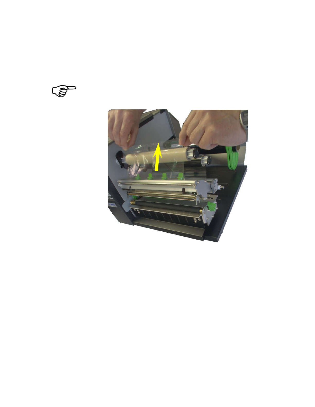
10. Route the ribbon to the rewind spindle and fasten it to the
ribbon sleeve (turn up the ribbon once so that the adhesive
part at the beginning of the ribbon can be used. Adhesive
tape can be used, if need be).
Fig. 4.2.1.j Routing the ribbon to the rewind spindle and fasten it
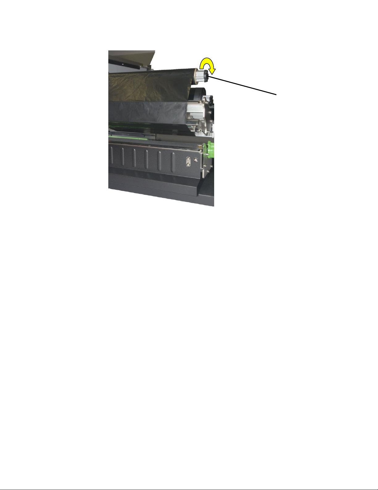
11. Wind the ribbon rewind spindle clockwise 3 to 5 rotations to
tauten the ribbon.
_______________________________________________________________________________________________
MICROPLEX Operator’s Manual LOGIJET T8-3 Edition 1.0prel
Page 34
34 Handling of Consumables
Ribbon rewind
spindle
_______________________________________________________________________________________________
Fig. 4.2.1.k Tautening the ribbon by winding the ribbon rewind spindle
12. Check that the ribbon has no folds and is running straight.
If necessary, tauten the ribbon a little bit more by further
winding of the ribbon rewind spindle. Finally the ribbon has
to be firmly attached to the ribbon sleeve.
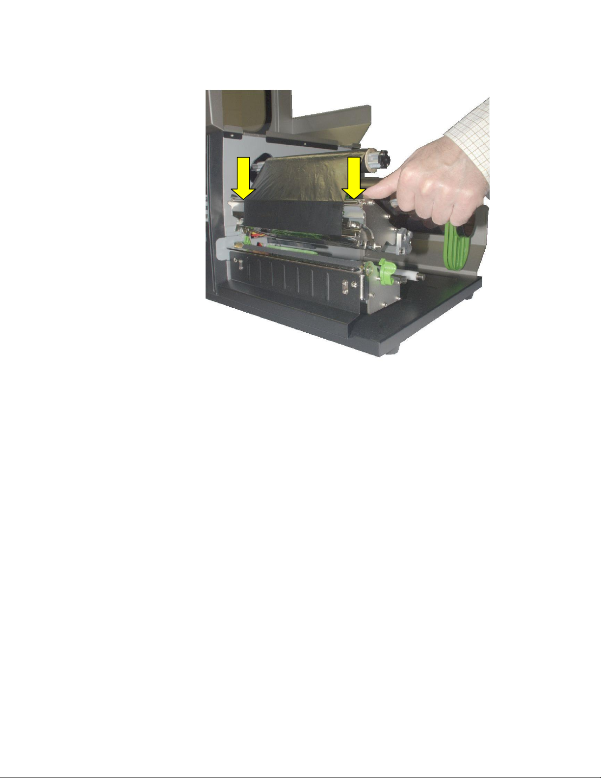
13. Swivel the printhead mechanism back to its original position
using both hands and making sure it clicks into place (force
is needed).
_______________________________________________________________________________________________
MICROPLEX Operator’s Manual LOGIJET T8-3 Edition 1.0prel
Page 35
Handling of Consumables 35
_______________________________________________________________________________________________
Fig. 4.2.1.l Swivelling the printhead mechanism with both hands down until it
clicks into place
_______________________________________________________________________________________________
MICROPLEX Operator’s Manual LOGIJET T8-3 Edition 1.0prel
Page 36

36 Handling of Consumables
The unused ribbon can remain within the device until it is
used for the next thermal transfer operation (if necessary
protect the ribbon against unintentional unwinding).
The ribbon has to be loaded as described in section
4.2.1.
_______________________________________________________________________________________________
4.2.2. Ribbon Removal
The following steps are necessary if you want to switch from
printing in the thermal transfer mode to printing in the thermal
direct mode. In case only a used-up ribbon has to be removed
the steps 5 and 6 have to be omitted.
1. Switch the printer to OFF LINE mode.
2. Open the the printer hood completely.
3. Push the printhead release lever clockwise to open the print
head mechanism.
4. The core of a used-up ribbon can be removed by pulling it
from the ribbon supply spindle.
5. If the inserted ribbon is not used-up, cut it close to the
ribbon rewind spindle.
6. Rotate the ribbon supply spindle until the free end of the
ribbon is winded up.
7. Rotate the rewind spindle until the free end of the used-up
ribbon is winded up.
8. Remove the used-up ribbon from the rewind spindle and
dispose it according to the rules.
The media for thermal direct printing has to be loaded as
described in section 4.3.1.
_______________________________________________________________________________________________
MICROPLEX Operator’s Manual LOGIJET T8-3 Edition 1.0prel
Page 37
Handling of Consumables 37
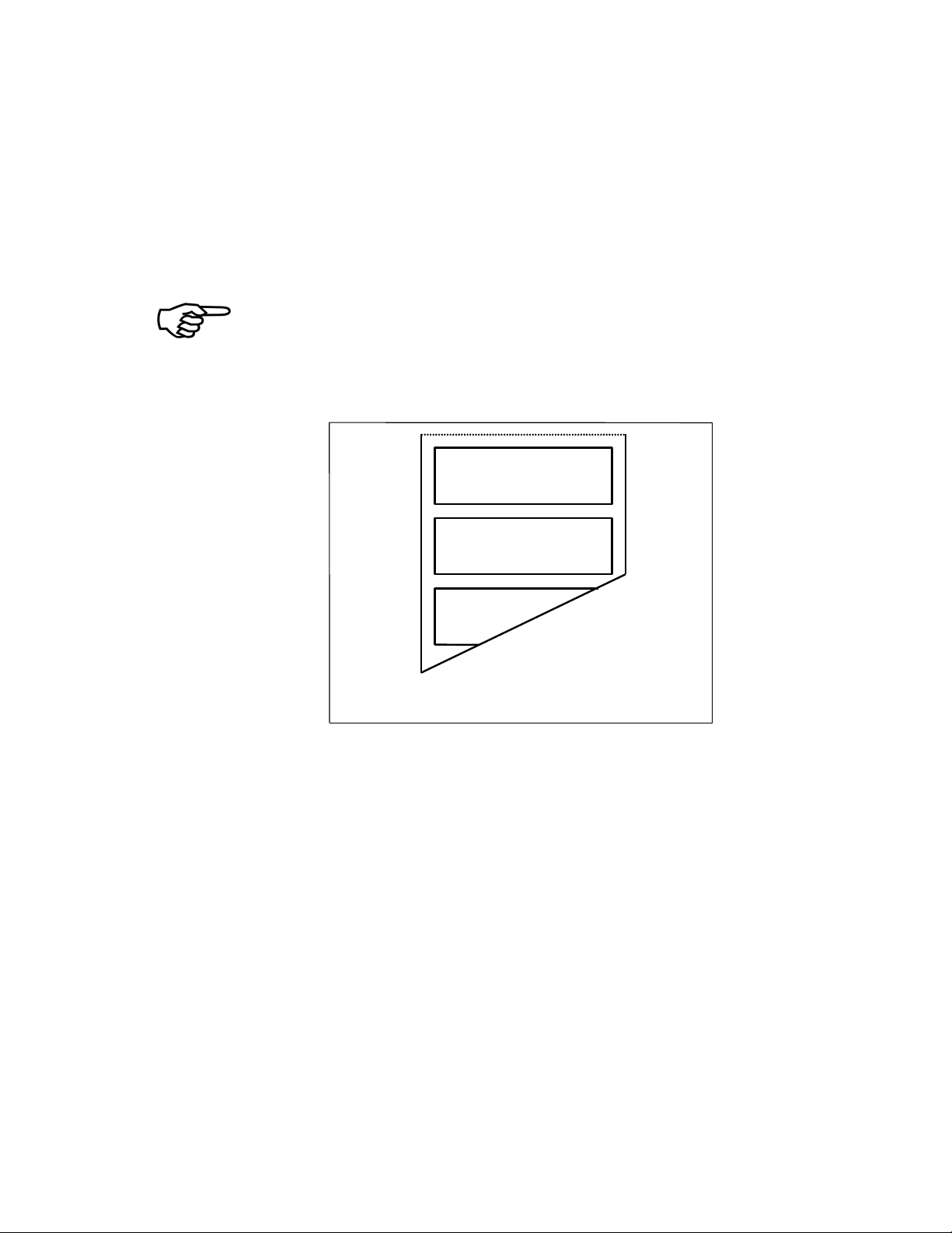
The tear off roll-fed media is easier to insert if the end is gored
before inserting as shown in the figure below (when using a
new roll you should first remove the protection foil if necessary
and discard one full turn of the media).
_______________________________________________________________________________________________
4.3. Roll-Fed Media Handling
4.3.1. Roll-fed Media Loading
To load roll-fed media for tear off respectively for further external
processing go on like this:
Fig. 4.3.1.a Goring the tear off roll-fed media
1. Switch the printer to OFF LINE mode.
2. Open the printer hood completely.
_______________________________________________________________________________________________
MICROPLEX Operator’s Manual LOGIJET T8-3 Edition 1.0prel
Page 38
38 Handling of Consumables
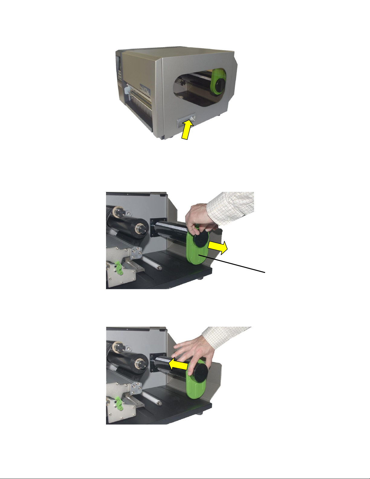
Front
Label roll guide
_______________________________________________________________________________________________
Fig. 4.3.1.b Opening the printer hood
3. Remove one label roll guide (the front one which is facing
the viewer; the second label roll guide has to stay on the
label supply spindle).
_______________________________________________________________________________________________
MICROPLEX Operator’s Manual LOGIJET T8-3 Edition 1.0prel
Fig. 4.3.1.c Removing one label roll guide
4. Move the remaining second label roll guide backwards on
the lable supply spindle.
Fig. 4.3.1.d Movingthe secnd label roll guide backwards
Page 39
Handling of Consumables 39
_______________________________________________________________________________________________
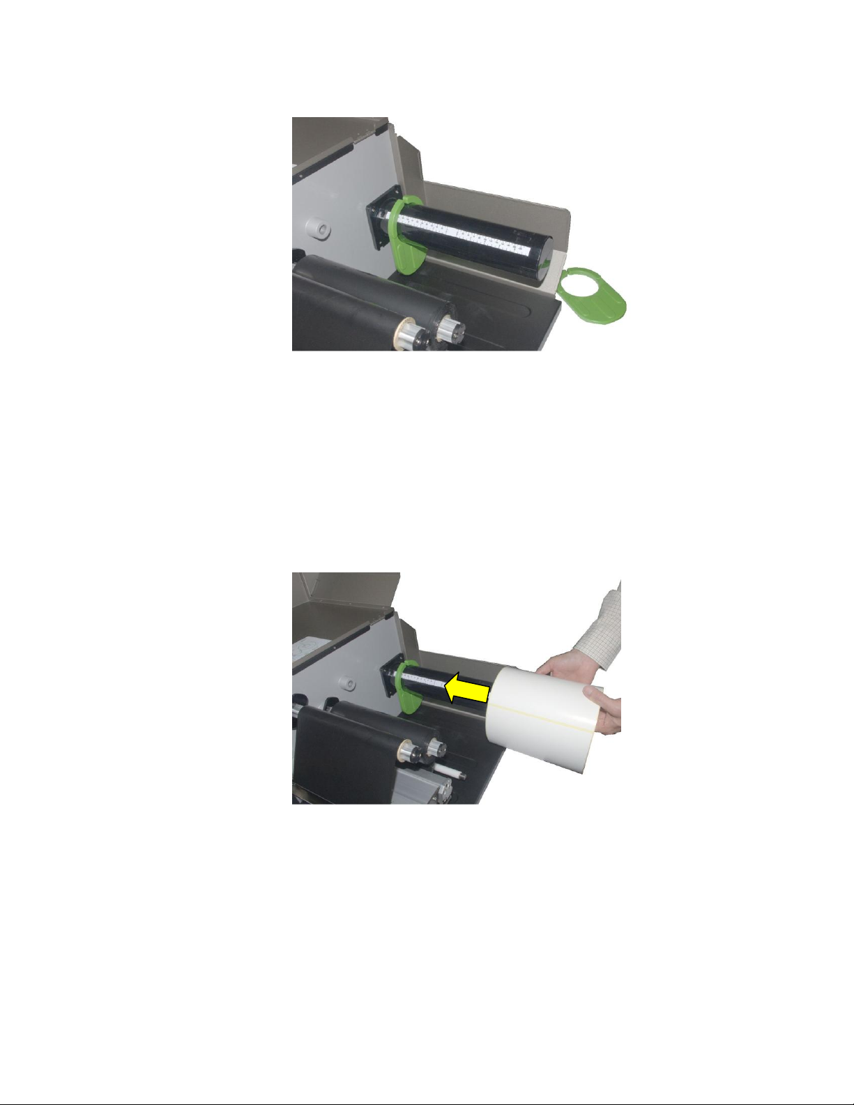
Fig. 4.3.1.e Printers label roll supply spindle ready for the label roll
5. The media roll must turn counterclockwise when unwinding.
Take the Tear off roll-fed media and hold it in the
corresponding way.
6. Slide the media roll onto the printer’s label roll supply spindle.
Please note: The media roll has to be mounted centered, use
the scale on the supply spindle for this operation.
Fig. 4.3.1.f Sliding the media roll onto the label roll supply spindle
and then centering the media roll
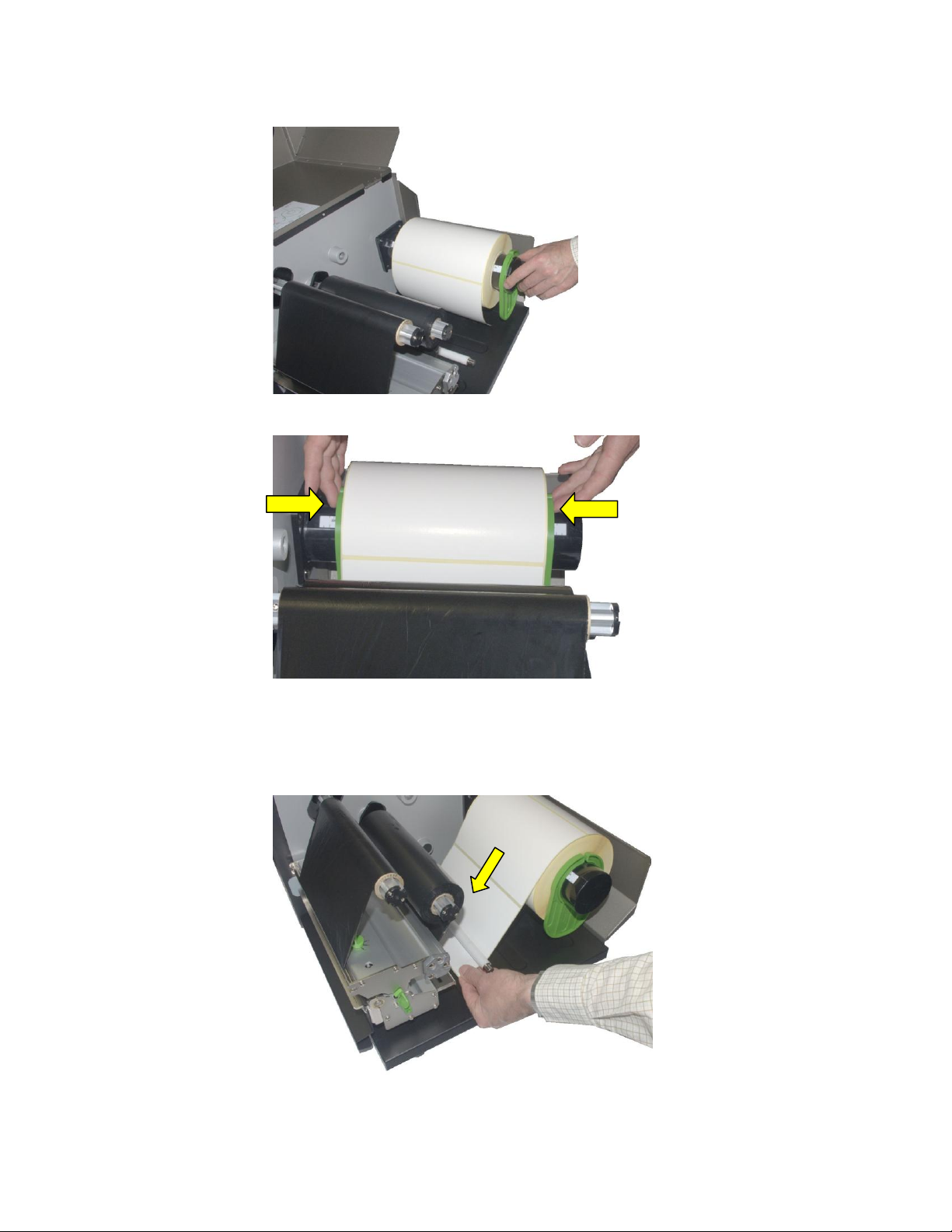
7. Reassemble the front label roll guide and move both guides
towards the media roll.
Please note: The media roll still has to be in a centered
position on the label roll supply spindle after that.
_______________________________________________________________________________________________
MICROPLEX Operator’s Manual LOGIJET T8-3 Edition 1.0prel
Page 40
40 Handling of Consumables
_______________________________________________________________________________________________
Fig. 4.3.1.g Reassembling the front label roll guide
Fig. 4.3.1.h Moving both label roll guides towards the media roll
8. Take the free end of the label roll and route it towards the
printhead as shown in the folling figure.
Fig. 4.3.1.i Routingthe free end towards the printhead
_______________________________________________________________________________________________
MICROPLEX Operator’s Manual LOGIJET T8-3 Edition 1.0prel
Page 41
Handling of Consumables 41
_______________________________________________________________________________________________
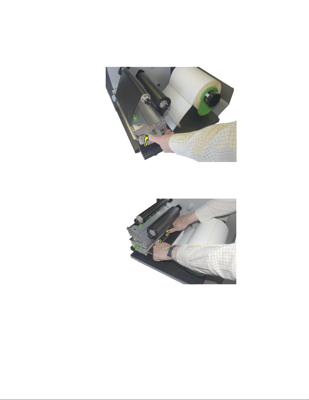
9. Push the printhead release lever clockwise to open the print
head mechanism (compare figure 4.2.1.a, too).
Fig. 4.3.1.j Pushing the printhead release lever
10. Slide the material guide to its outermost position (maximum
throughput width).
Fig. 4.3.1.k Adjusting the material guide to the maximum throughput width
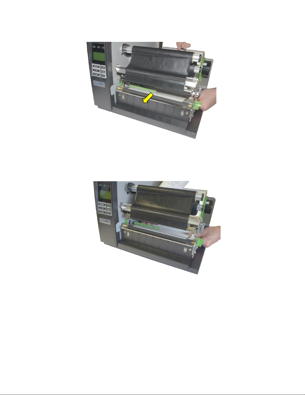
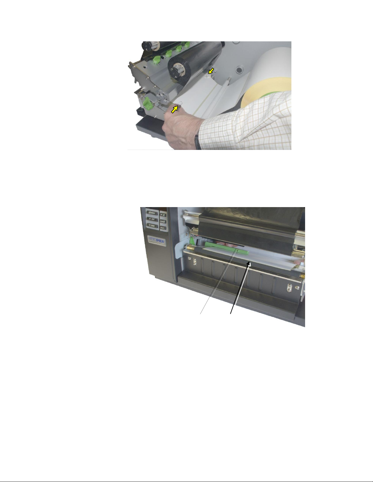
11. Feed the label material through the printer and out of the
printer passing the media sensor (therefore you have to
feed the label material through the “fork” of this sensor).
Compare figure 2.4.e to locate this part of the printer.
_______________________________________________________________________________________________
MICROPLEX Operator’s Manual LOGIJET T8-3 Edition 1.0prel
Page 42
42 Handling of Consumables
_______________________________________________________________________________________________
Fig. 4.3.1.l Feeding the media out of the printer
12. Align the media in a centered position to ensure a straight
transport.
Fig. 4.3.1.m Centering the media inside the printer
13. Adjust the material guide to the current material widh
without deforming the material (see the following figure and
compare figure 4.3.1.k).
_______________________________________________________________________________________________
MICROPLEX Operator’s Manual LOGIJET T8-3 Edition 1.0prel
Page 43
Handling of Consumables 43
Gap Sensor Reflex Sensor
(GAP) (Blackmark)
(Material/Media Sensors; green)
_______________________________________________________________________________________________
Fig. 4.3.1.n Adjusting the material guide to the current material
14. Please adjust the sensors of your printer to your current
consumables:
_______________________________________________________________________________________________
MICROPLEX Operator’s Manual LOGIJET T8-3 Edition 1.0prel
Fig. 5.3.1o Preview: Position of the Sensors
15. Details are described in section 6.1.2 Checking and
Adjusting the Sensors and in the following sections,
where the associated panel functions are described.
Page 44
44 Handling of Consumables
_______________________________________________________________________________________________
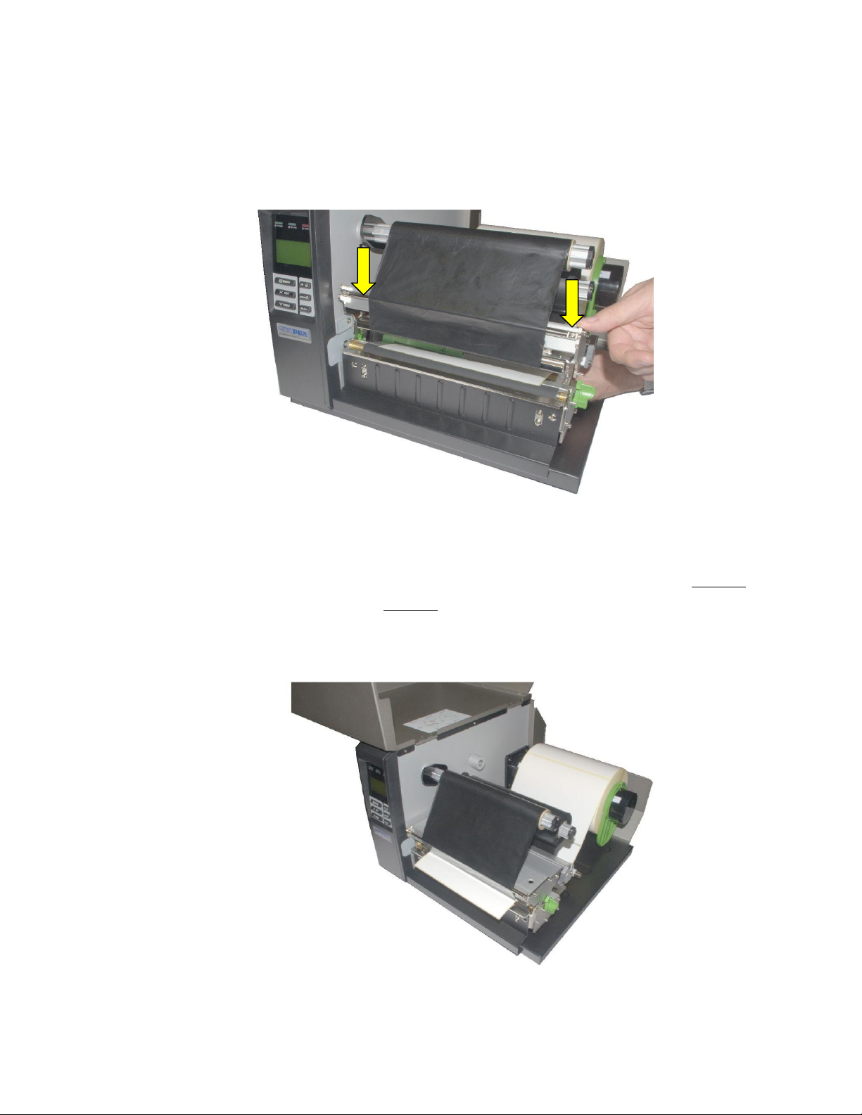
16. Swivel the printhead mechanism back to its original position
using both hands and making sure it clicks into place (force
is needed).
Fig. 4.3.1.p Swivelling the printhead mechanism down until it clicks into place
Please note: The printer now is ready to print using the thermal
transfer process.
If you want to print using the thermal direct
process, you first have to remove the ribbon (foil).
Fig. 4.3.1.q Printer ready for thermal transfer printing
_______________________________________________________________________________________________
MICROPLEX Operator’s Manual LOGIJET T8-3 Edition 1.0prel
Page 45

Handling of Consumables 45
Pay attention to the following safety instructions!
Safety instructions:
- The cutter (optional) can cause injuries if the printer is
operated incorrectly.
- There is a danger of fingers, hair, clothing, jewellery etc.
being drawn into the machine in the vicinity of the ribbon
and media transport unit.
_______________________________________________________________________________________________
17. Close the hood of the printer.
18. Before starting the printer first please read chapter 5
Operation and Menu Structure.
19. Use the printer’s control panel to select the appropriate
print process.
Details are described in section 6.2
Print Process Selecting.
20. Wird ein Farbband verwendet, muss am Bedienfeld auch
die richtige Farbbandabwickelrichtung eingestellt werden.
Details are described in section 6.3
Ribbon Unwinding Setting (Ink Inside or Outside).
_______________________________________________________________________________________________
MICROPLEX Operator’s Manual LOGIJET T8-3 Edition 1.0prel
Page 46

46 Handling of Consumables
_______________________________________________________________________________________________
4.3.2. Media Removal
1. Switch the printer to OFF LINE mode.
2. Open the hood of the printer.
3. Push the printhead release lever clockwise to remove the
media (see section 4.1 Winding Diagram) and pull away
the material to the rear.
4. Rotate the tear off roll-fed media roll clockwise until the free
end of the media is winded up.
5. Remove the roll with the tear off roll-fed media (if necessary
protect the media against unintentional unwinding first).
6. Close the hood of the printer.
_______________________________________________________________________________________________
MICROPLEX Operator’s Manual LOGIJET T8-3 Edition 1.0prel
Page 47
Handling of Consumables 47
- Printing should always be carried out with the lightest contact
pressure possible for creating a satisfactory print quality. This
protects the printhead and the entire device.
- Excessive contact pressure can result in premature wearing of
the printhead.
_______________________________________________________________________________________________
4.4. Printhead Pressure Adjusting
In the factory this printer is set to the optimum values for the
standard printing application. The printout quality and the
occurrence of ribbon wrinkles, however, depend on a large
number of factors.
In particular the current material width and/or material thickness
have an large effect on the contact pressure of the thermal
printhead on the media and the platen roller.
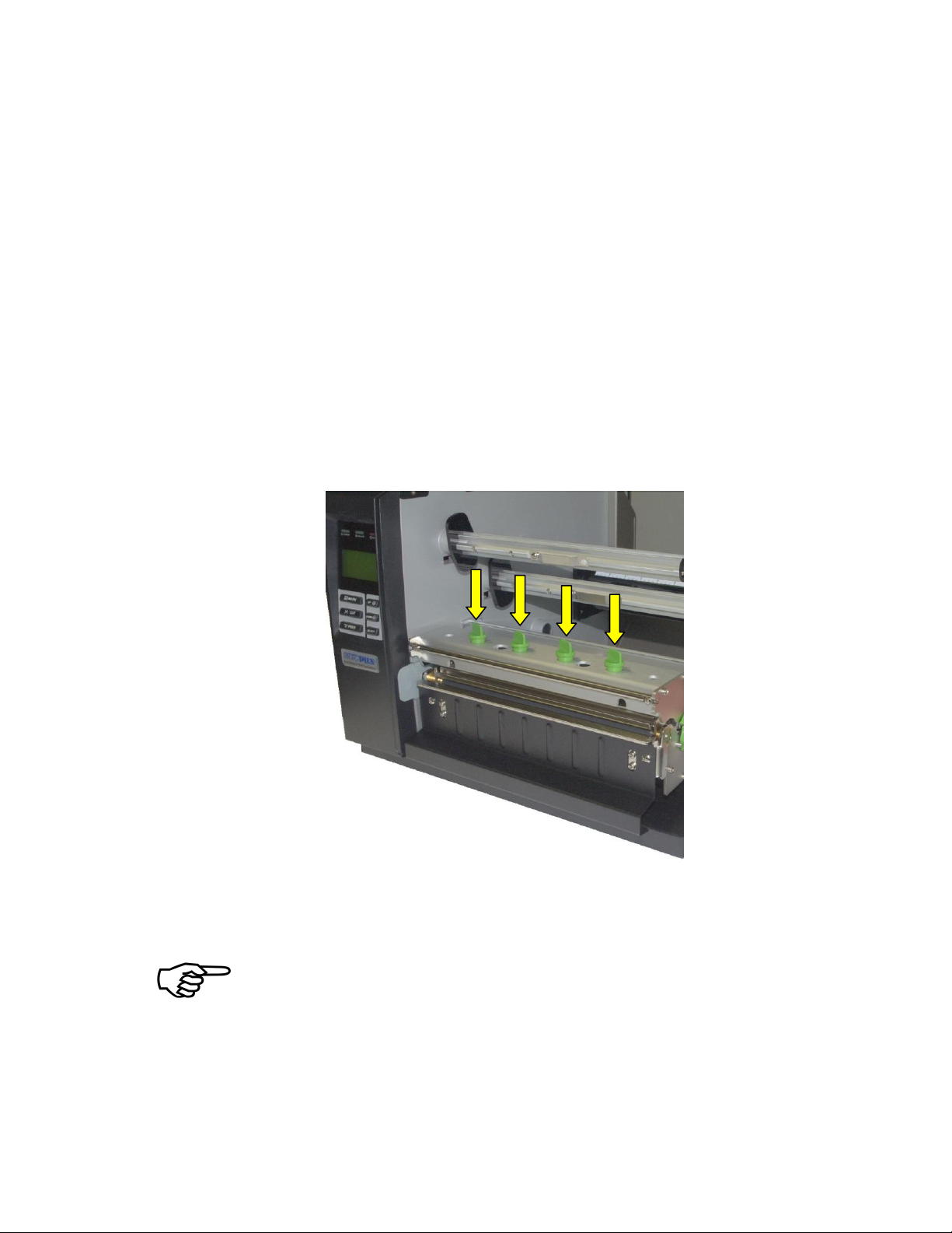
To allow a compensation of such influences, the contact pressure
of the printhead is adjustable by 4 adjustment knobs.
The 4 green adjustment knobs are located above the printhead:
Fig. 4.4.a Printhead contact pressure: Position of the 4 adjustment knobs
Please note:
_______________________________________________________________________________________________
MICROPLEX Operator’s Manual LOGIJET T8-3 Edition 1.0prel
Page 48

48 Handling of Consumables
_______________________________________________________________________________________________
A) Printhead pressure adjusting in a ballanced way:
1. Open the printer hood completely.
2. Push the printhead release lever clockwise to open the print
head mechanism.
3. If you want a better accessibility to the 4 green adjustment
knobs you can temporarily remove the ribbon first (compare
section 4.2.2 Ribbon Removal).
4. Please adjust the printhead pressure in the desired direction
by adjusting all 4 adjustment knobs in the same
way.
Using the green adjustment knobs 5 levels for the prindhead
pressure can be choosen; level 1 causes the lowest pressure.
Adjusting the knobs clockwise will increase the printhead
pressure.
5. Swivel the printhead mechanism back to its original
position using both hands and making sure it clicks into
place (force is needed).
6. Generate a test print.
7. Repeat step 2 to 6 until you are satisfied with the printout
quality.
_______________________________________________________________________________________________
MICROPLEX Operator’s Manual LOGIJET T8-3 Edition 1.0prel
Page 49
Handling of Consumables 49
Adjustment knobs
right side
Adjustment knobs
left side
_______________________________________________________________________________________________
B) Printhead pressure adjusting on one side:
If (only) one side of the media is printed with good printout quality
or ribbon wrinkles occur, you have the possibility to choose an
“asymmetrical setting” for the adjustment knobs. This
allows an corresponding optimization of the printhead pressure.
Please note: Before choosing such an “asymmetrical setting” you
should check the handling of all consumables first
(compare chapter 4). If, for example, one of the
ribbon rolls isn’t mounted centered this already might
be the cause of wrinkles.
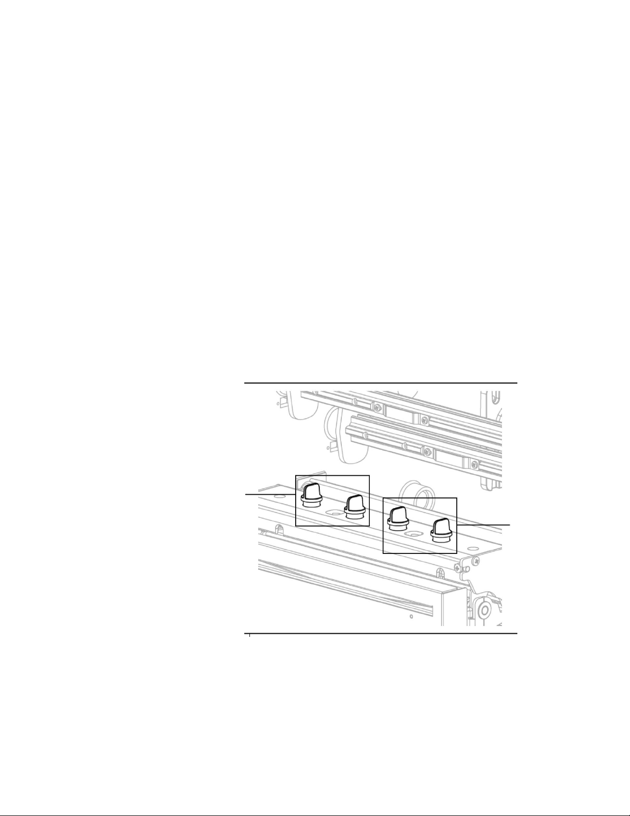
If an “asymmetrical setting“ for the printhead is indeed
necessary, the adjustment knobs have to be divided into two
groups:
Fig. 4.4.b Printhead pressure: Dividing the Adjustment knobs in two groups
Adjust the printhead pressure in the desired manner by adjusting
either te right side adjustment knobs or the knobs of
the left side.
_______________________________________________________________________________________________
MICROPLEX Operator’s Manual LOGIJET T8-3 Edition 1.0prel
Page 50

50 Handling of Consumables
_______________________________________________________________________________________________
Hints for the error situation „Ribbon wrinkles“:
- Use the last test print to check the „direction“ of the wrinkle.
The wrinkle can happen from the lower left to the upper right
direction (error image „ ´ “; seen in the printer’s feed direction).
On the other hand the wrinkle can happen from the lower right
to the upper left direction (error image „ ` “).
- Error image „ ´ “ : First of all please reduce the printhead
pressure on the right side by adjusting the 2 adjustment knobs
of the right side both about one step counterclockwise.
If both adjustment knobs already show level „1“ (i.e. the lightest
contact pressure is already chosen) then please increase the
printhead pressure on the left side by adjusting the 2 adjustment
knobs of the left side both about one step clockwise.
- Error image „ ` “ : The descriptions from above shall also
apply by analogy – you only have to interchange the words
„right“ and „left“.
- Generate a test print.
- Repeat the steps described above until you reach a satisfactory
print quality.
_______________________________________________________________________________________________
MICROPLEX Operator’s Manual LOGIJET T8-3 Edition 1.0prel
Page 51
Operation and Menu Structure 51
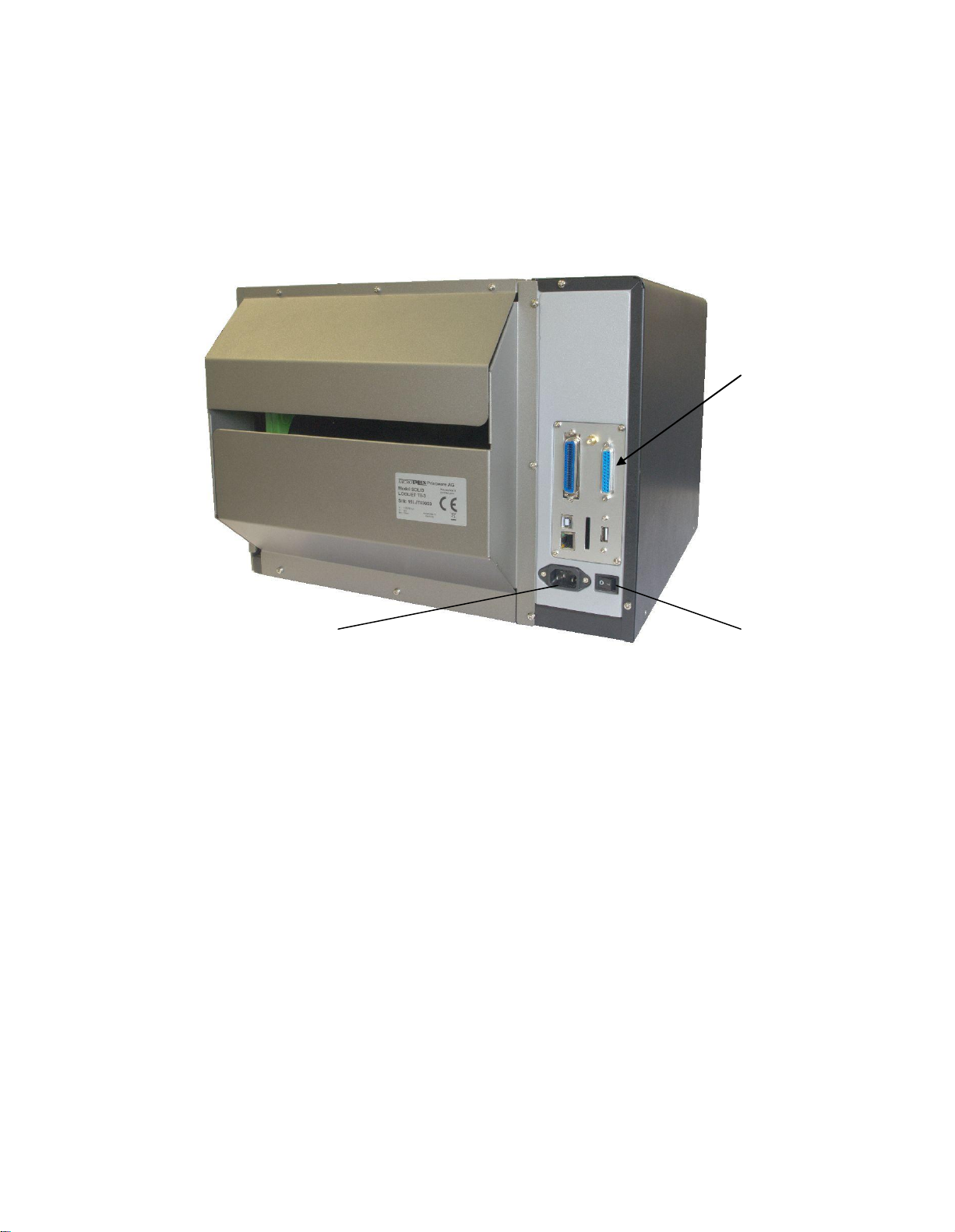
Interfaces
Socket for the
power cord
Power switch
_______________________________________________________________________________________________
5. Operation and Menu Structure
5.1. Attaching the Printer to a Network/PC
Fig. 5.1.a Rear view of the LOGIJET T8-3
1. Make sure the printer, the computer, and any other attached devices
are turned off and unplugged.
2. Use a proper interface line to connect the printer to your computer or to
the network.
The printer LOGIJET T8-3 is provided with several interfaces. See figure
2.4.d in chapter 2 and chapter 10 Specifications.
_______________________________________________________________________________________________
MICROPLEX Operator’s Manual LOGIJET T8-3 Edition 1.0prel
Page 52

52 Operation and Menu Structure
Please notice the instructions given in chapter 4 Handling of
Consumables.
The print system requires time to initialize and to warm up after you
turn it on.
_______________________________________________________________________________________________
5.2. Turning on the Printer
1. Plug one end of the printer power cord into the socket at the back of the
printer and the other end into a properly grounded outlet.
2. Turn on the printer. The power switch is located at the back side of the
printer (near the printer’s paper output opening, see section 5.1.a).
As soon as the printer’s warm up phase is finished the printer goes into
the ON LINE mode. A status message and the name of the printer are
displayed.
Note: You can change the language that appears on the touch panel.
Use the Display Language Selection panel function (see section 6.19).
_______________________________________________________________________________________________
MICROPLEX Operator’s Manual LOGIJET T8-3 Edition 1.0prel
Page 53
Operation and Menu Structure 53
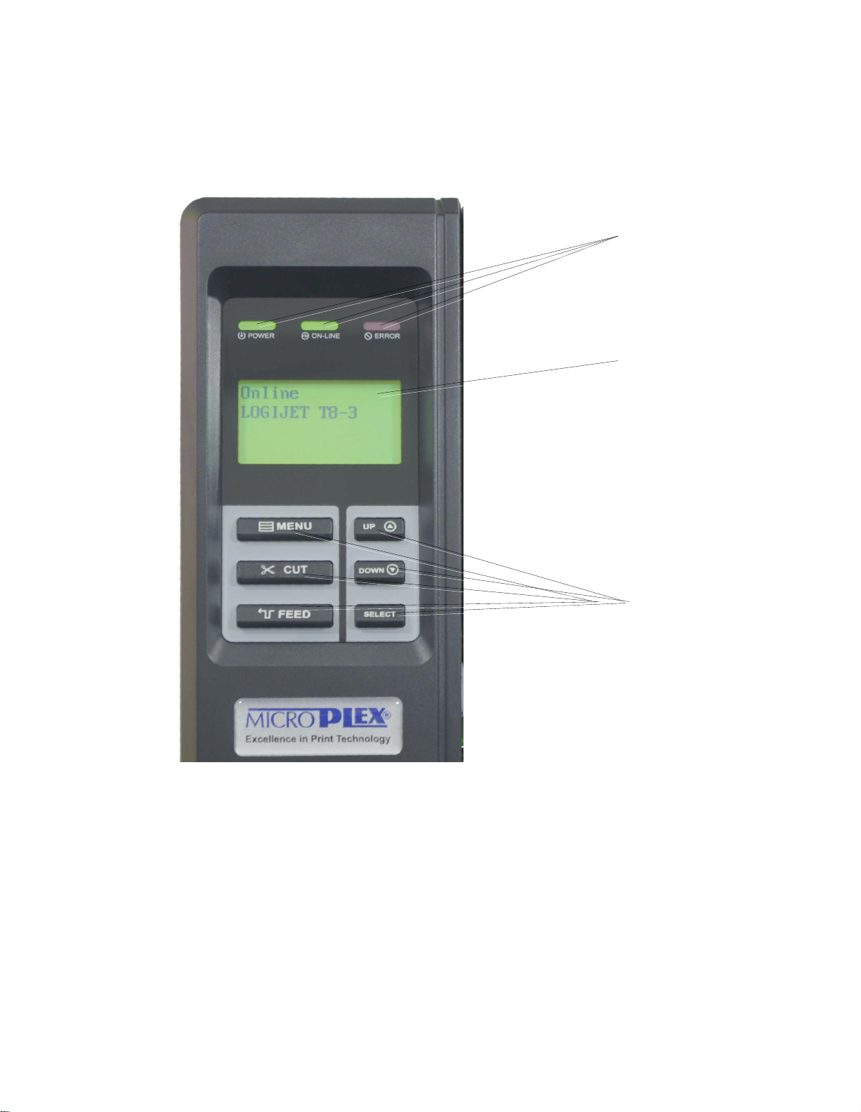
Display
(fourlined)
6 Function
keys
LEDs
_______________________________________________________________________________________________
5.3. Control Panel View
_______________________________________________________________________________________________
MICROPLEX Operator’s Manual LOGIJET T8-3 Edition 1.0prel
Page 54

54 Operation and Menu Structure
The printer is on.
The printer is off.
The printer is ready to receive data from the host (the printer is
ON LINE).
The printer is not ready to receive data from the host (OFF LINE).
The control panel keys are active.
An error occurred in the printer. The printer is OFF LINE.
No error occurring.
_______________________________________________________________________________________________
5.4. Function of the Control Panel Elements
Display
The display (LCD-panel, 4 x 16 characters) serves to show the
printer’s status messages.
POWER – LED (Green)
ON LINE – LED (Green)
ERROR – LED (Red)
_______________________________________________________________________________________________
MICROPLEX Operator’s Manual LOGIJET T8-3 Edition 1.0prel
Page 55
Operation and Menu Structure 55
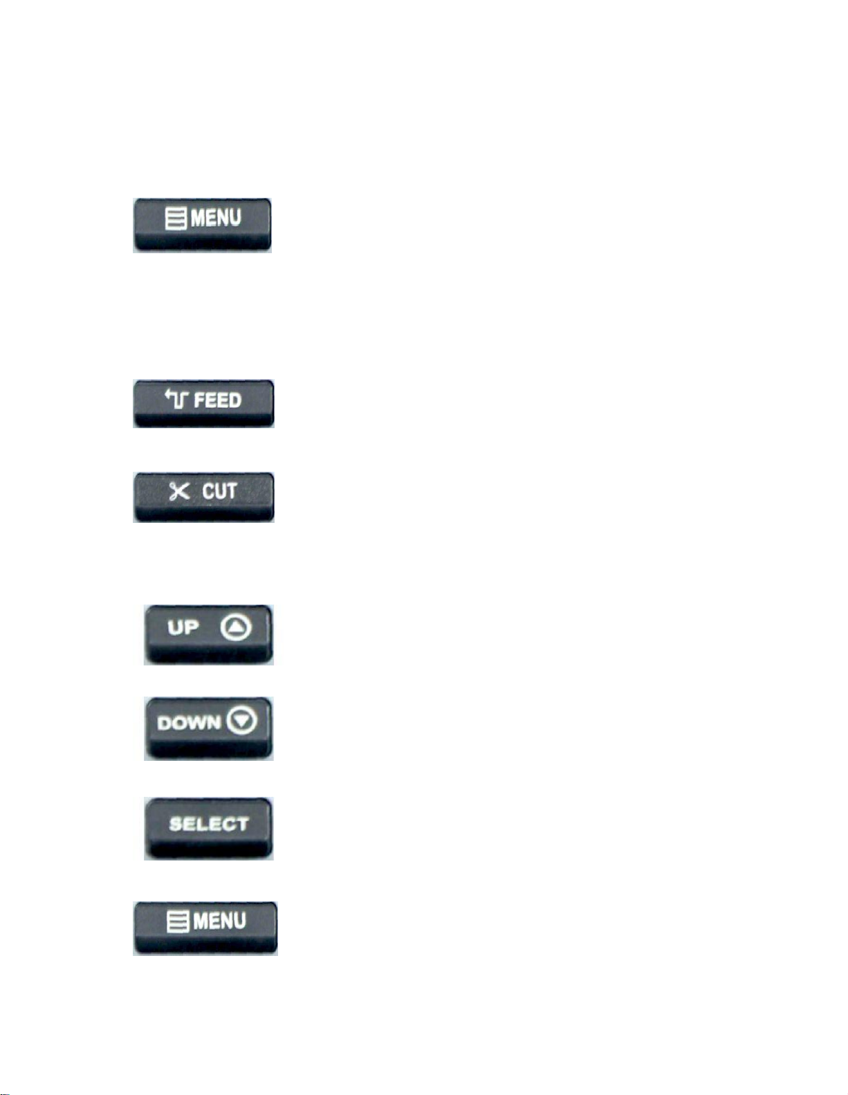
Printer OFF LINE:
This symbol shows the MENU key. This key is used to turn the
printer OFF LINE and ON LINE.
In addition to that this key can be used to clear an error message
in the display after the fault was fixed.
In the OFF LINE mode the paper is conveyed one format
length further after having activated the FEED key.
In the OFF LINE mode this key is used to start the cutter
(cutter = option).
These keys are used for working within the different levels of the
menu structure.
This structure and the panel functions are described in the
following.
_______________________________________________________________________________________________
Control Panel Keys
_______________________________________________________________________________________________
MICROPLEX Operator’s Manual LOGIJET T8-3 Edition 1.0prel
Page 56

56 Operation and Menu Structure
_______________________________________________________________________________________________
5.5. Configuration via the Control Panel
You can use the control panel to change the printer configuration and
customize your printer to meet your specific needs.
In addition printer configuration via Ethernet is possible.
The MICROPLEX printer controller offers an integrated website, for
more information see Networking Features of MICROPLEX Printers.
Chapter 6 (Panel Functions) describes how to reach the particular
printer functions via the panel.
T e m p o r a r y changes in printer configuration are effective only as
long as the printer stays turned on. To select such changes temporarily,
the user must terminate the change of function by pressing the
key one single time.
P e r m a n e n t changes in printer configuration are active each time
the printer is turned on again. To select such changes permanently, the
user must terminate the change of function by pressing the
key two times.
An output of the current printer values can be generated using the
panel function Printing the Status Sheet (see section 6.9).
Please note:
User default settings remain in effect until you save new settings
or restore the factory defaults.
Settings you choose from your software application or printer
driver can also change or override the user default settings you
select from the touch panel.
_______________________________________________________________________________________________
MICROPLEX Operator’s Manual LOGIJET T8-3 Edition 1.0prel
Page 57

Operation and Menu Structure 57
[LOGIJET T8-3 ]
[Menu Level 1 ]
After the printer was turned on (and as soon as the warm up phase
is finished) the printer goes into the ON LINE – Mode
Printer messages are displayed on the control panel display.
This symbol shows the MENU key. This key is used to turn the
printer OFF LINE
If the printer is turned OFF LINE with this key you get automatically
into the first menu level.
Now this message is displayed on the display.
In the interest of simplicity, in the following chapters only the most
important display messages are shown in the Panel display column.
_______________________________________________________________________________________________
Switching the Printer OFF LINE
_______________________________________________________________________________________________
MICROPLEX Operator’s Manual LOGIJET T8-3 Edition 1.0prel
Page 58
58 Operation and Menu Structure
ON LINE mode
OFF LINE
Menu Level 1
Status Sheet
Hexdump
Normal Print/FF
Cancel Job
Menu Page
Sliding Pattern
Buffer-Dump
Paper Menu
Page Length
in inch
Two-Up Mode
Configuration
Interface
SIA Timeout
RS 232 #)
RS 232 Protocol
RTS/CTS
XON/XOFF
Baudrate
RS 232 Fm.
None
Emulation
Language
Input Buffer
Transparent Code
Config. Word
User Config.
Select
Define
Factory Default
Page Menu
Font Number
Orientation
Margin
Left
from Right
Top
from Bottom
Engine
Print Direct.
Material
in mm
Line Spacing
Symbol Code
Time Setting
Date Setting
Char. Spacing
Paper Width
Network
Font List
Extended Menu
in 1/300 inch
Key Lock
RFM
Line Termination
File Management
Directory
Process
Printspeed
Density
Image X-Pos.
TearOff Mode
Ribbon Unwinding
TearOff Menu
Service Mode
TearOff Position
Dot Test
Image Y-Pos.
Pattern Test
Sensor Test
in inch
in mm
Timeout
Y-Direction
X-Direction
in 1/300 inch
Sync.-Menu
Sync.Sens.Type
Sync.Sens.Level
Sync.Sens.Offset
Periph. Device
. . .
Sync.Sens.Logic
Change by IF
NumberOfCopies
PCL Y-Offset
Auto.Sens.Adj.
Print Mode
Paper Size
Print-Files
Measure length
Auto.Measurement
MediaEnd Detect.
DHCP
Manual
Off
IP Address
Subnet Mask
Gateway
IP Assign
SNMP
Ethernet
AP
Copy WiFi Config
Wifi #)
#) Optional
Last Error
. . .
Slip Correction
. . .
_______________________________________________________________________________________________
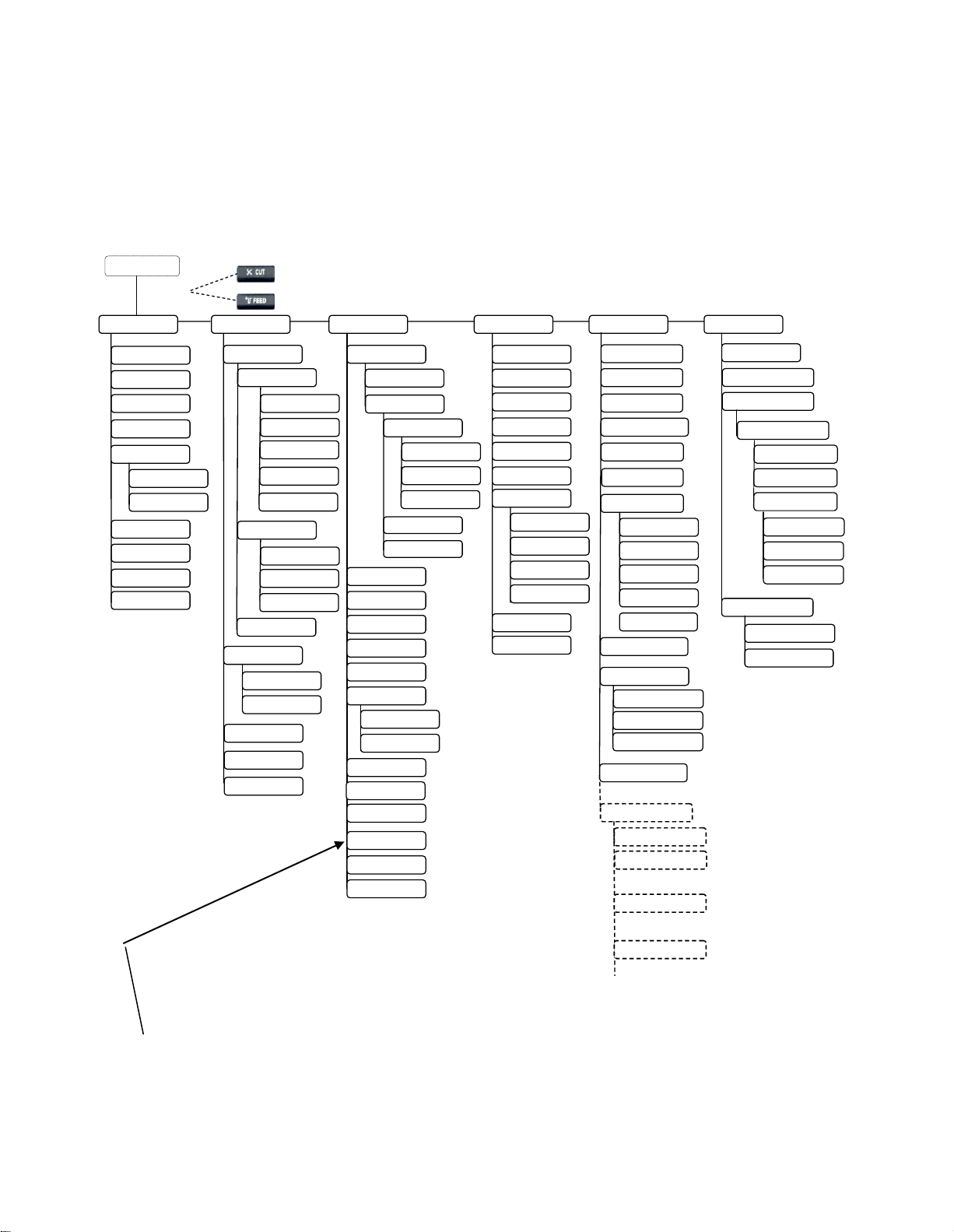
5.6. Menu Structure
Access to the menu structure is possible as soon as the printer is turned
OFF LINE.
The menu structure of the printer LOGIJET T8-3 is arranged in different levels:
This panel function allows the user to choose a reduced menu instead of the
extended menu shown above.
_______________________________________________________________________________________________
MICROPLEX Operator’s Manual LOGIJET T8-3 Edition 1.0prel
Page 59
Operation and Menu Structure 59
["Menu Level"]
["Function"]
This symbol shows the MENU key. You get automatically into
menu level 1, if the printer is turned OFF LINE with this key.
By pressing the key or the key you can
move within the menu levels.
Each menu item/subitem within a menu level is shown in the
display.
The key has two main functions. It gives the user
access to a particular menu and, once in the menu, it allows the
user to select a particular function.
_______________________________________________________________________________________________
Selecting positions in the menu structure:
_______________________________________________________________________________________________
MICROPLEX Operator’s Manual LOGIJET T8-3 Edition 1.0prel
Page 60
60 Operation and Menu Structure
The keys and change the value of the selected
digit of the function value.
By pressing the key the selected function is activated
respectively the function values currently displayed are confirmed.
In case of a multi-digit function value the key is used to switch
to the next position of the function value (DIGIT).
Pressing the key switches to the previous digit of the
function value.
Please note: If you press the key although the absolute left
digit of the function value is still arrived, the changing
procedure will be cancelled and this moves you to the
next menu level above.
If you press the key although the absolute right
digit (digit 1) of the function value is still arrived, the
currently displayed function value is stored.
_______________________________________________________________________________________________
Functions / Changing of function values:
_______________________________________________________________________________________________
MICROPLEX Operator’s Manual LOGIJET T8-3 Edition 1.0prel
Page 61
Operation and Menu Structure 61
[Save as Setup?]
Pressing the key the displayed function value is confirmed
respectively the displayed function is activated.
The changes are saved temporay. (This means, the changes are saved
only until the next printer power off).
After this you have to decide, if you want to save the changes
permanent (Save as setup).
To select such changes permanently, the user must press the
key one more time. These permanent changes in printer
configuration are active each time the printer is turned on again.
If the key is pressed instead, the changes are only stored
temporary (not saved as setup).
(This key takes the user to the respective previous menu level).
_______________________________________________________________________________________________
_______________________________________________________________________________________________
MICROPLEX Operator’s Manual LOGIJET T8-3 Edition 1.0prel
Page 62
62 Operation and Menu Structure
Pressing the key takes the user back to the respective
menu level above.
Pressing the key switches the user directly to
ON LINE from any menu position. For this you have to press the
key longer than 2 seconds.
_______________________________________________________________________________________________
Return to the menu level above:
Return to the ON LINE mode:
_______________________________________________________________________________________________
MICROPLEX Operator’s Manual LOGIJET T8-3 Edition 1.0prel
Page 63
Operation and Menu Structure 63
["Message"]
The control panel functions will be described using diagrams. These
diagrams show the course necessary in order to activate a certain
function.
First the elements of the diagrams are explained:
The sequence on the left describes which keys have to be pressed
briefly in succession.
In this example the key has to be pressed first. Then the
key has to be released and the key has to be
pressed. Then the key has to be released and the
key has to be pressed.
The Panel display column shows the display messages
corresponding to the sequences listed on the left.
In the column Notes explanations to particular operational steps
are given.
_______________________________________________________________________________________________
5.7. Syntax of Diagrams
_______________________________________________________________________________________________
MICROPLEX Operator’s Manual LOGIJET T8-3 Edition 1.0prel
Page 64

64 Panel Functions
_______________________________________________________________________________________________
6. Panel Functions
For the panel functions described in the following, the printer is
presumed to be switched on and in the ON LINE mode.
6.1. Selecting and Adjusting the Sync Sensors
Please note: Always adjust the printer sensors to your consumables (sensor
position as well as the levels and currents).
_______________________________________________________________________________________________
MICROPLEX Operator’s Manual LOGIJET T8-3 Edition 1.0prel
Page 65
Panel Functions 65
The Gap Sensor (Transparent Photoelectric Switch) is suitable for labels
with transparent or register gaps (Menu sub-point Punched). The Reflex Sensor
(Reflex Photoelectric Switch) is suitable for materials with markings / Black
Marks (Menu sub-point Reflex).
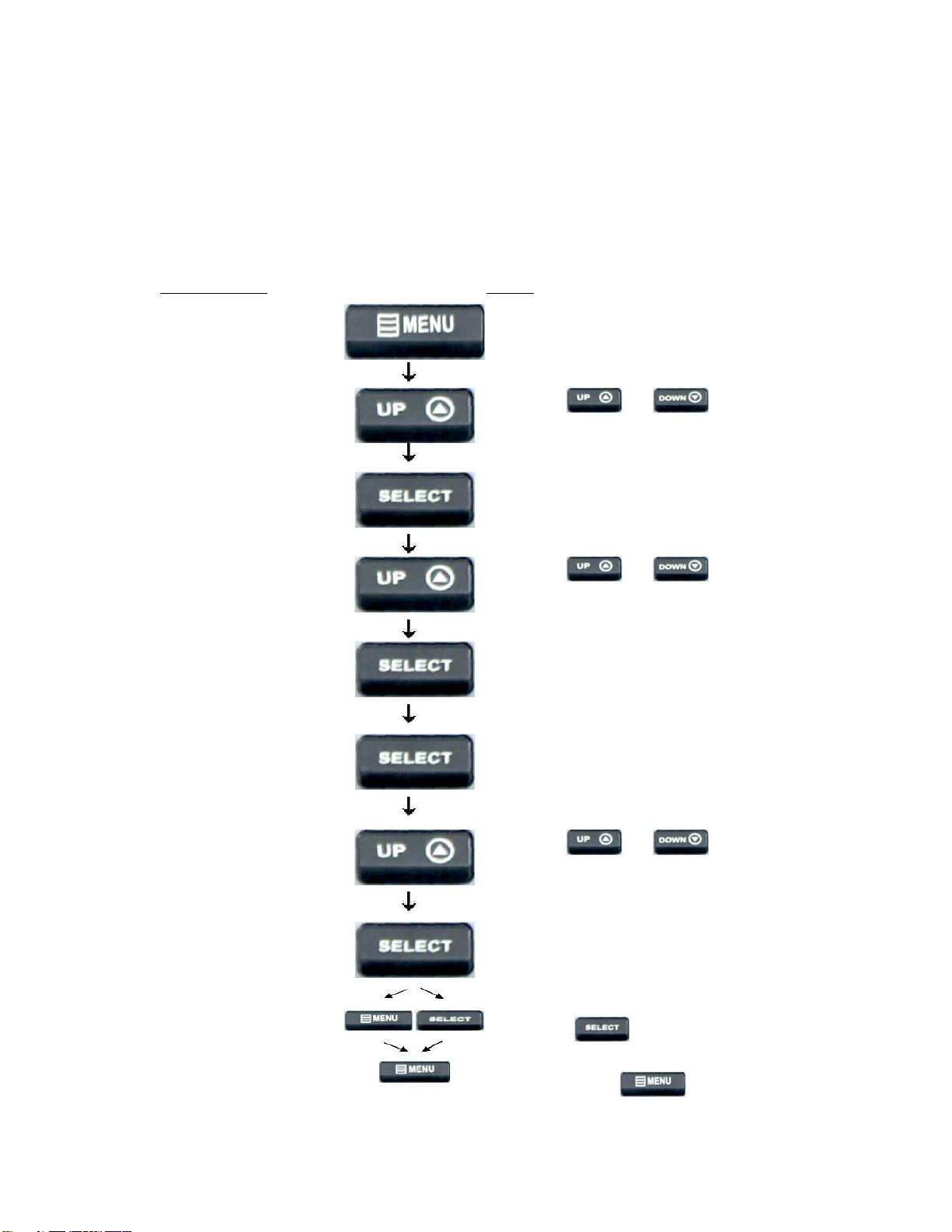
Panel display
Notes
[Online ]
Turn the printer OFF LINE with this key.
[Menu Level 1 ]
. . .
Press the or key until [Engine ] is
displayed.
[Engine ]
Press this key. This selects the Engine menu.
[Printspeed ]
. . .
Press the or key until [Sync.Menu ] is
displayed.
[Sync.Menu ]
Press this key. This selects the Sync menu.
[Sync.Sens.Type ]
Press this key. This selects the Sync.Sens.Type menu.
[Punched ]
The currently set value is displayed.
. . .
Press the or key until the desired sensor
type is displayed.
[Reflex ]
The reflex sensor is selected.
[Save as Setup? ]
[Online ]
In addition this new value can be saved as setup value
(using the key), before the printer is turned ON
LINE again. After this decision turn the printer ON LINE
again: Press the key longer than 2 seconds.
_______________________________________________________________________________________________
6.1.1. Selecting the Light Sensor Type (Gap or Reflex)
_______________________________________________________________________________________________
MICROPLEX Operator’s Manual LOGIJET T8-3 Edition 1.0prel
Page 66
66 Panel Functions
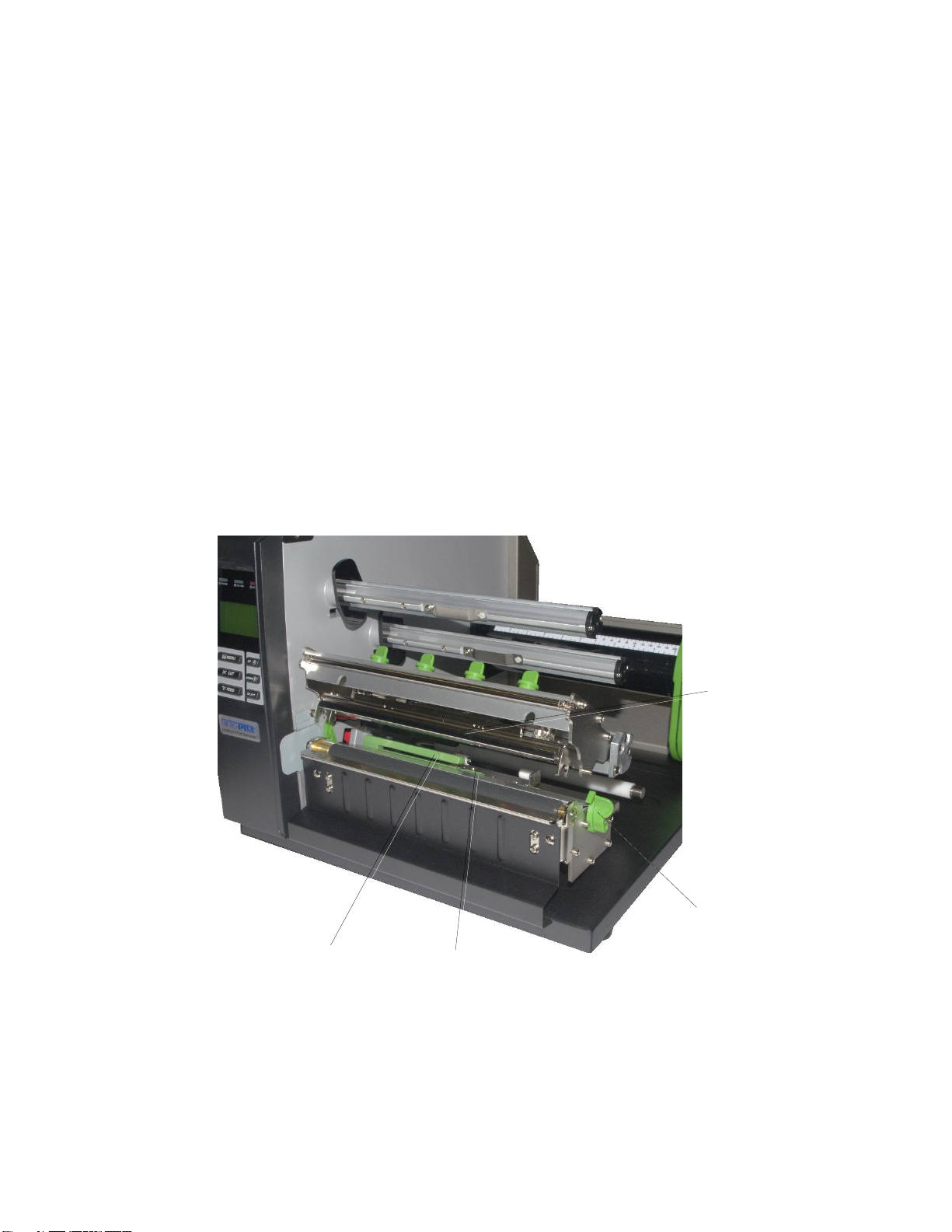
The device is provided with sensors to enable controlling of consumable
movements (Synchronization).
The Gap sensor (Transparent sensor) as well as the Black mark sensor (Reflex
sensor) are located “below” the printhead mounting.
Printhead release
lever
Transparent sensor Reflex sensor
(GAP) (Black mark)
(Material/media sensors; green)
Printhead
_______________________________________________________________________________________________
6.1.2. Checking and Adjusting the Sensors
Adjust the sensors to your consumables:
Please note: The sensors are located under the print unit.
Always adjust all sensors to your current consumables (levels and currents
as well as sensor position).
1. Open the printer hood completely.
2. Push the printhead release lever clockwise to open the printhead
mechanism.
Fig. 6.1.2.a Printhead mechanism opened
_______________________________________________________________________________________________
MICROPLEX Operator’s Manual LOGIJET T8-3 Edition 1.0prel
Page 67
Panel Functions 67
Printhead
Media
Sensors required
Sensor position mark
Media with Black marks
Reflex sensor (Black mark)
(+ transparent sensor for
paper end detection)
Directly over the black mark
Die-cut label
Transparent sensor (Gap)
The middle of media
Center-punched hole tag
Transparent sensor (Gap)
Directly over the hole
Notched tag
Transparent sensor (Gap)
Directly over the notch
Transparent sensor Reflex sensor
(GAP) (Black mark)
Printhead
_______________________________________________________________________________________________
3. Insert the consumable or measure the position of the gaps/marks.
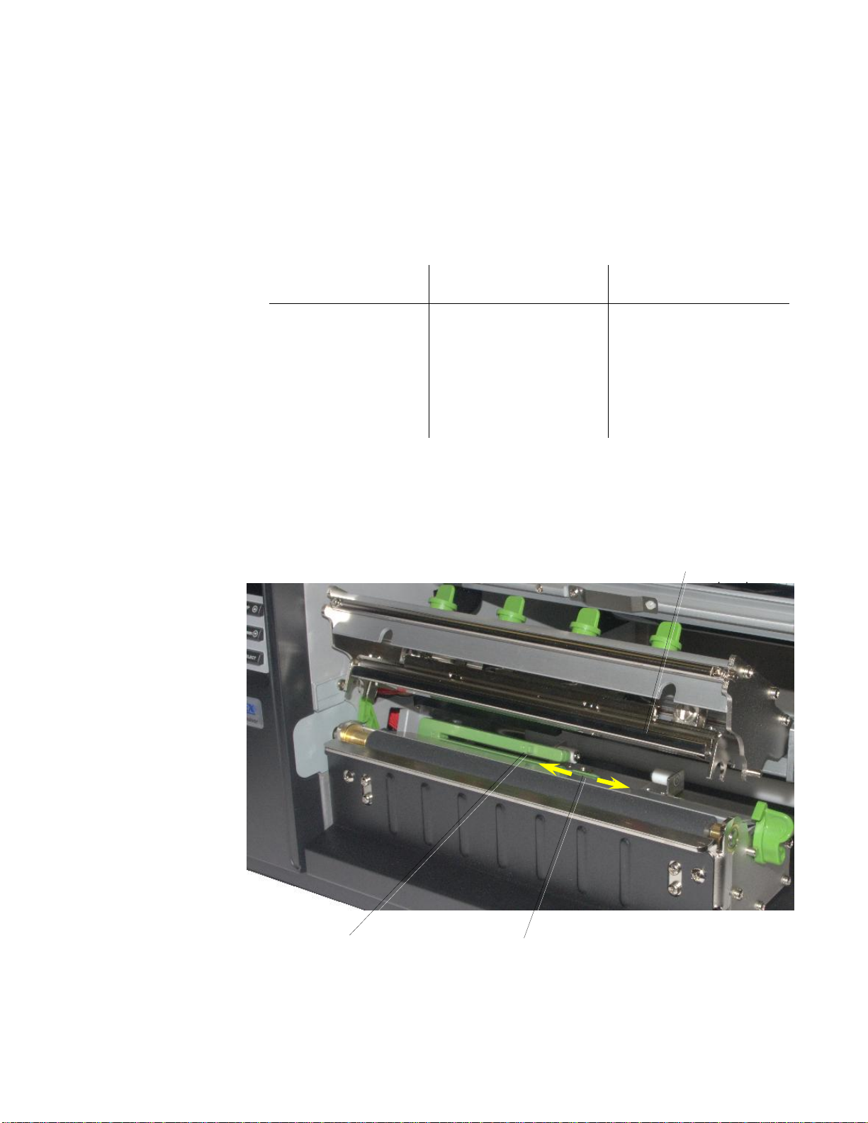
4. The following table gives you an overview of media and sensor
target positions:
5. Set the Reflex sensors to the lateral position of the marks of your
material. (Compare the yellow arrows in the following figure.)
Fig. 6.1.2.b Sliding the sensor to the accurate position
_______________________________________________________________________________________________
MICROPLEX Operator’s Manual LOGIJET T8-3 Edition 1.0prel
Page 68
68 Panel Functions
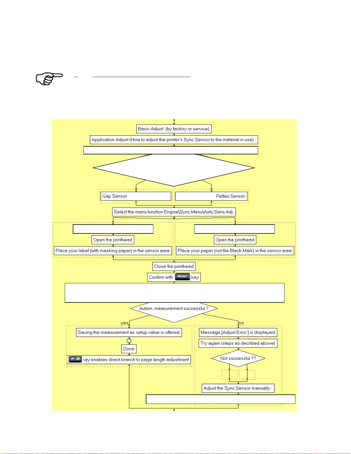
This function serves to adjust the printer’s Sync Sensors to the material in use.
If this automatic function does not work with your specific print material, please
perform the steps described in section 6.1.4 Manual Adjusting of Sensor Current
and Switching Threshold.
See section Manual Adjusting of Sensor Current and Switching Threshold
Select the light sensor type
(Engine\Sync.Menu\Sync.Sens.Type)
Shift the Reflex sensor to the accurate position (compare previous sections)
Message [Load Label] is displayed
Message [Load Paper] is displayed
Please follow the instructions (liner measurements):
Message [Load Liner] … Message [Load Black Mark]
During the automatic measurement [Please Wait ] is displayed
_______________________________________________________________________________________________
6.1.3. Automatic Adjust of Sensor Current and Switching Threshold
6.1.3.1. Overview
_______________________________________________________________________________________________
MICROPLEX Operator’s Manual LOGIJET T8-3 Edition 1.0prel
Page 69
Panel Functions 69
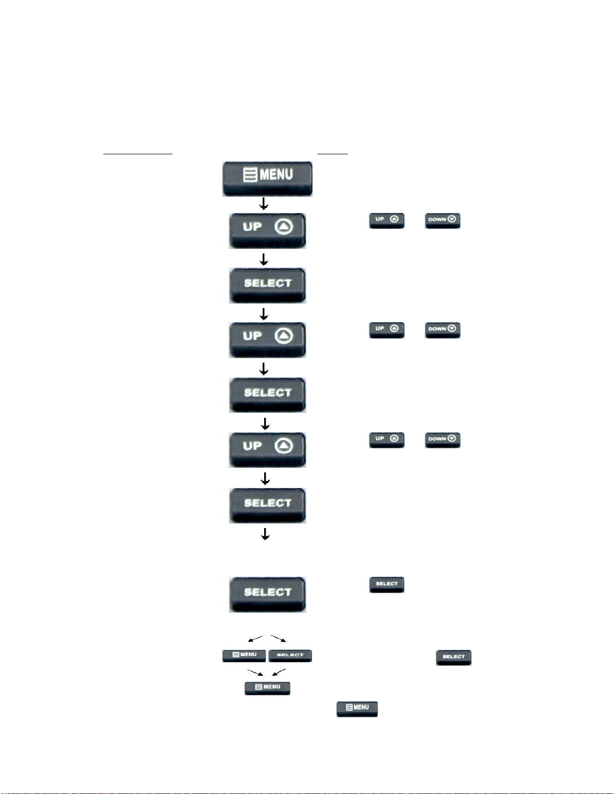
Selecting the Light Sensor Type (Gap or Reflex) is described in section 6.1.1.
In this example the steps to adjust the Gap Sensor are described.
Panel display
Notes
[Online ]
Turn the printer OFF LINE with this key.
[Menu Level 1 ]
. . .
Press the or key until [Engine ]
is displayed.
[Engine ]
Press this key. This selects the Engine menu.
[Printspeed ]
. . .
Press the or key until
[Sync.Menu ] is displayed.
[Sync.Menu ]
Press this key. This selects the Sync menu.
[Sync.Sens.Type ]
. . .
Press the or key until
[Auto.Sens.Adj. ] is displayed.
[Auto.Sens.Adj. ]
Press this key to start the automatic sensor
adjusting.
[Put in Label ]
Open the printhead and place label (with
masking paper) in the sensor area.
Close the printhead.
. . .
Press the key: the printer automatically
measures the contrast value. Please follow the
instructions (liner measurement).
[Save as Setup? ]
[Online ]
In addition this new value can be saved as
setup value (using the key), before the
printer is turned ON LINE again. After this
decision turn the printer ON LINE again: Press
the key longer than 2 seconds.
_______________________________________________________________________________________________
6.1.3.2. Example
_______________________________________________________________________________________________
MICROPLEX Operator’s Manual LOGIJET T8-3 Edition 1.0prel
Page 70

70 Panel Functions
Manual adjusting of the Sync sensor current and switching threshold allows
the processing of materials with high contrast proof points within the label,
which would otherwise be falsely measured by the system. *)
The panel functions Sensor Test and Sync Sens Level serve to adjust the
Sync sensors specifically for the label material in use.
The following sections describe the steps to adjust the Black mark sensor
(reflex sensor) and the Gap sensors (transparent sensor) in form of flow charts
as well as in form of step by step listings.
_______________________________________________________________________________________________
6.1.4. Manual Adjusting of Sensor Current and Switching Threshold
*) Special solution: If the adjusting of the Gap Sync sensor failes because the contrast
value of the label material itself is very low, you can use the panel function
Sync.Sens.Logic to invert the logic. (Black marks can be used as “inverse gaps”
_______________________________________________________________________________________________
MICROPLEX Operator’s Manual LOGIJET T8-3 Edition 1.0prel
in this way.)
Page 71
Panel Functions 71
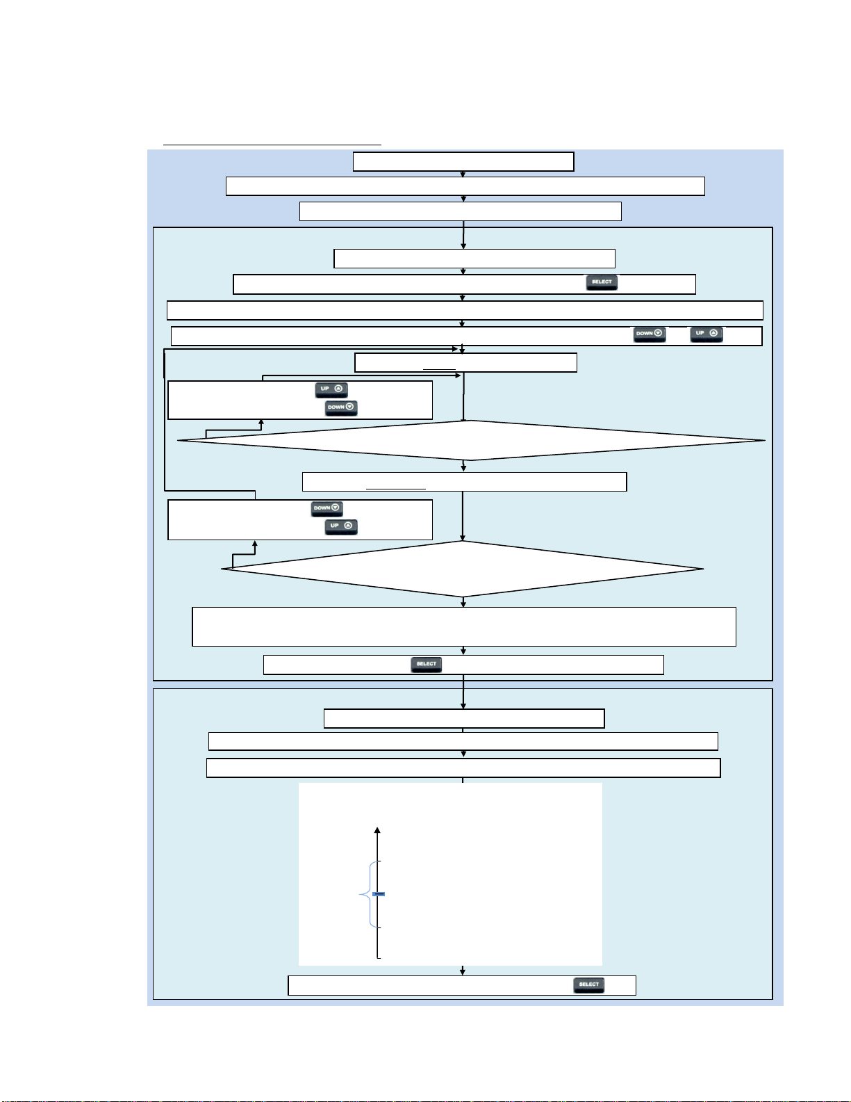
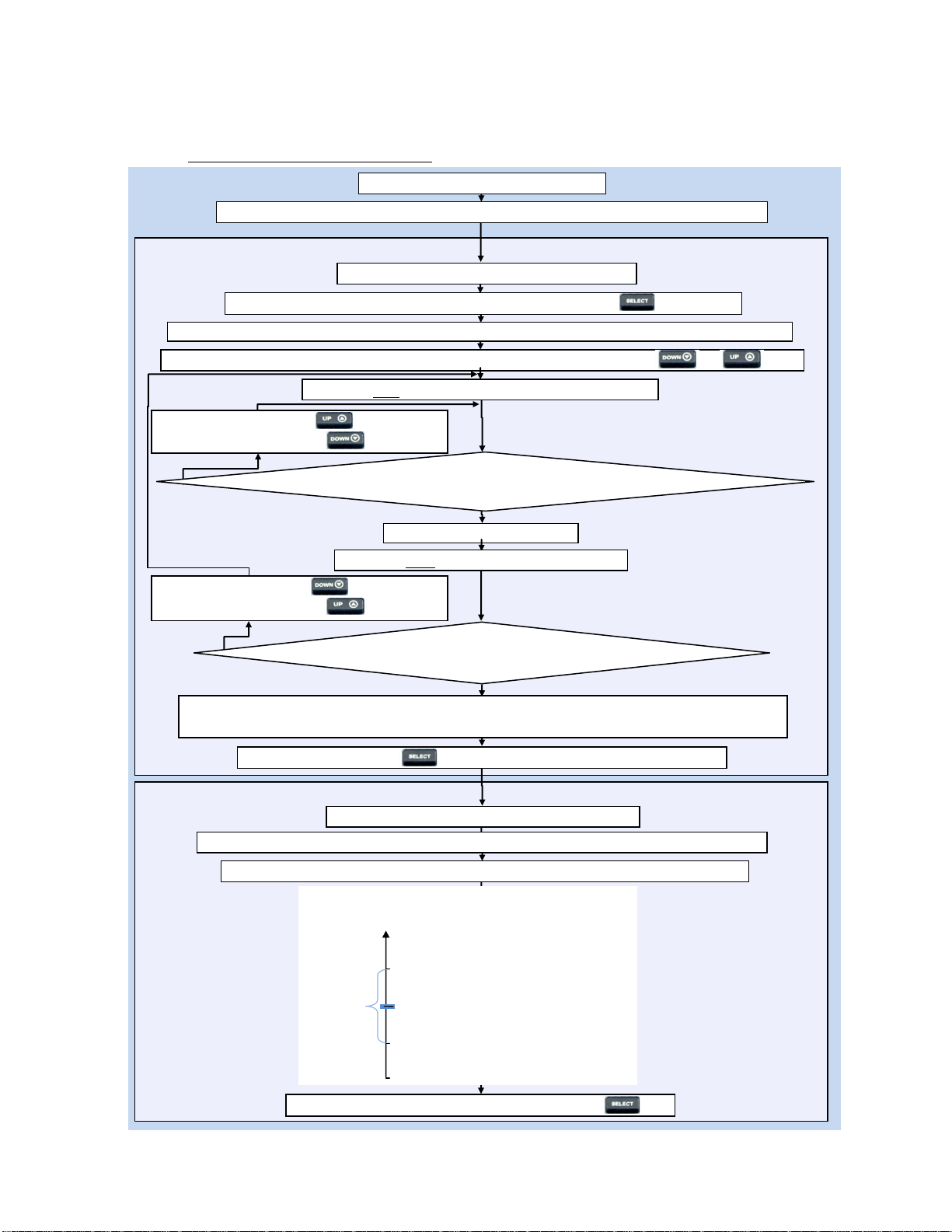
Set the Reflex sensor current (CV value) as follows:
In the printer Menu go to Engine\Sync.Menu\Sync.Sens.Type and select Reflex
Go to Engine\Sensor Test and select Reflex
Leftmost: VV= currently measured sensor value (Level) At the right: CV= reference value for sensor current
Load your paper into the sensor area
Set CV (reference value sensor current) in the first instance to approx. 60 % (using or key)
Increasing the CV current value ( key) reduces the
sensor measured value (VV level) ( key increases)
Sensor measured value (VV level) of black
mark as possible more than 45 % ?
Place the black mark of your material in the sensor area
Set the switching threshold of the Reflex sensor:
Set the switching threshold to the middle between the paper level and the black mark level:
Save the new switching threshold (level) using the key
Yes
Yes
No
No
The level (contrast) measured by the sensor is displayed. Press once again
Measure both sensor levels once again, thereby notice the values for Paper and Black mark.
(You need the two level values of your material for the following switching threshold adjustment)
Save the new CV value ( ; CV = reference value sensor current)
At the right the switching threshold value is displayed.
Graphical explanation for switching threshold setting:
Level
in %
Black mark
Mean value is to be used as Switching threshold
Paper
0
Sensor measured value (VV level) of paper less than 10 % ?
Start the printer in the Service Mode
Reducing the CV current value ( key) increases the
sensor measured value (VV level) ( key decreases)
Go to Engine\Sync.Menu\Sync.Sens.Level
Shift the Reflex sensor to the position of the black marks
_______________________________________________________________________________________________
6.1.4.1. Reflex Sensor (Black Mark Sensor)
Working Steps as Flow Chart:
_______________________________________________________________________________________________
MICROPLEX Operator’s Manual LOGIJET T8-3 Edition 1.0prel
Page 72
72 Panel Functions
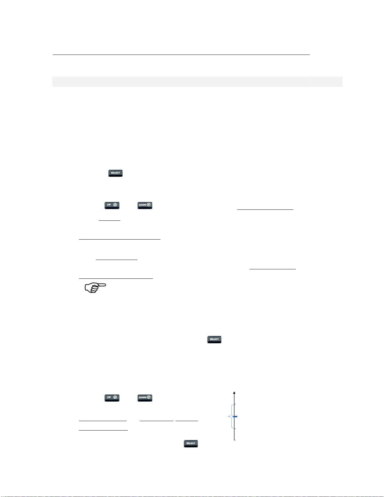
B) Select the Sensor Type
Reflex
Please go to [Sync.Sens.Type ] in the printer menu structure:
Engine\Sync.Menu\Sync.Sens.Type\ select Reflex
C) Shift the Reflex sensor to the position of your black marks
See section 6.1.2 Checking and Adjusting the Sensors
D) Sensor Current (CV value) adjusting
Please go to Sensor Test and select the subpoint Reflex:
Engine\Sensor Test\ select Reflex
The currently measured sensor level (contrast) is displayed.
Press the key again, after this 2 values are displayed:
Left VV = curr. measured sensor value (level) Right CV = reference value for sensor current.
CV is modifiable (and has an effect on the VV value).
Use the and keys to set the CV value. Approx. CV value:
Load paper into the sensor.
The sensor measured value (VV level) of the paper (not black mark)
should count less than 10%.
If the VV level is too high, increase CV (sensor current).
Put a black mark into the sensor area.
The sensor measured value (VV level) of the black mark should count as
possible more than 45 %.
If the sensor measured value (VV level) of black mark is too
low, the CV value should be decreased.
Higher black mark VV values than 45 % are more advantageous so
long as there is no rising above 10 % of the paper VV level.
Measure both sensor levels once again for Paper and Black mark.
(You need the two level values of your material for the following switching threshold adjustment)
Save the new current value (CV) using the key.
60 %
E) Sensor Switching Threshold adjusting
Please go to [Sync.Sens.Level ] in the printers menu structure:
Engine\Sync.Menu\Sync.Sens.Level
At the right the switching threshold value is displayed.
Use the and keys to set the
switching threshold of the sensor to the
middle between the paper level and the
black mark level:
Graphical explanation for switching threshold setting:
Level
in %
Black mark
Mean value is to be used as Switching threshold
Paper
0
_______________________________________________________________________________________________
Description of the Working Steps for the Reflex Sensor (Black Mark Sensor):
A) Start the printer in the Service Mode, compare section 6.32 (necessary for steps in section D).
_______________________________________________________________________________________________
MICROPLEX Operator’s Manual LOGIJET T8-3 Edition 1.0prel
Save the new switching threshold ( key).
Page 73
Panel Functions 73
Set the Gap sensor current (CV value) as follows:
Go to Engine\Sensor Test and select Gap
Leftmost: VV= currently measured sensor value (Level) At the right: CV= reference value for sensor current
Place the liner of your label material in the sensor area
Set CV (reference value sensor current) for the first time to approx. 25 % (using or key)
Increasing the CV current value ( key) reduces the
sensor measured value (VV level) ( key increases)
Set the switching threshold of the Gap sensor:
Save the new switching threshold (level) using the key
Yes
Yes
No
No
The level (contrast) measured by the sensor is displayed. Press once again
Measure both sensor levels once again, thereby notice the values for liner and label.
(You need the two level values of your material for the following switching threshold adjustment)
Save the new CV value ( key; CV = reference value for sensor current)
At the right the switching threshold value is displayed.
Graphical explanation for switching threshold setting:
Level
in %
Label (with liner)
Mean value is to be used as Switching threshold
Liner
0
Start the printer in the Service Mode
Reducing the CV current value ( key) increases the
sensor measured value (VV level) ( key decreases)
Go to Engine\Sync.Menu\Sync.Sens.Level
Increase CV by another 3 %
Sensor measured value (VV level) of
Sensor measured value (VV level) of label
as possible more than 40 % ?
Place the label (with liner) in the sensor area
In the printer Menu go to Engine\Sync.Menu\Sync.Sens.Type and select Punched
Set the switching threshold to the middle between the liner level and the label level:
_______________________________________________________________________________________________
6.1.4.2. Gap Sensor (Transparent Sensor)
Working Steps as Flow Chart:
_______________________________________________________________________________________________
MICROPLEX Operator’s Manual LOGIJET T8-3 Edition 1.0prel
Page 74
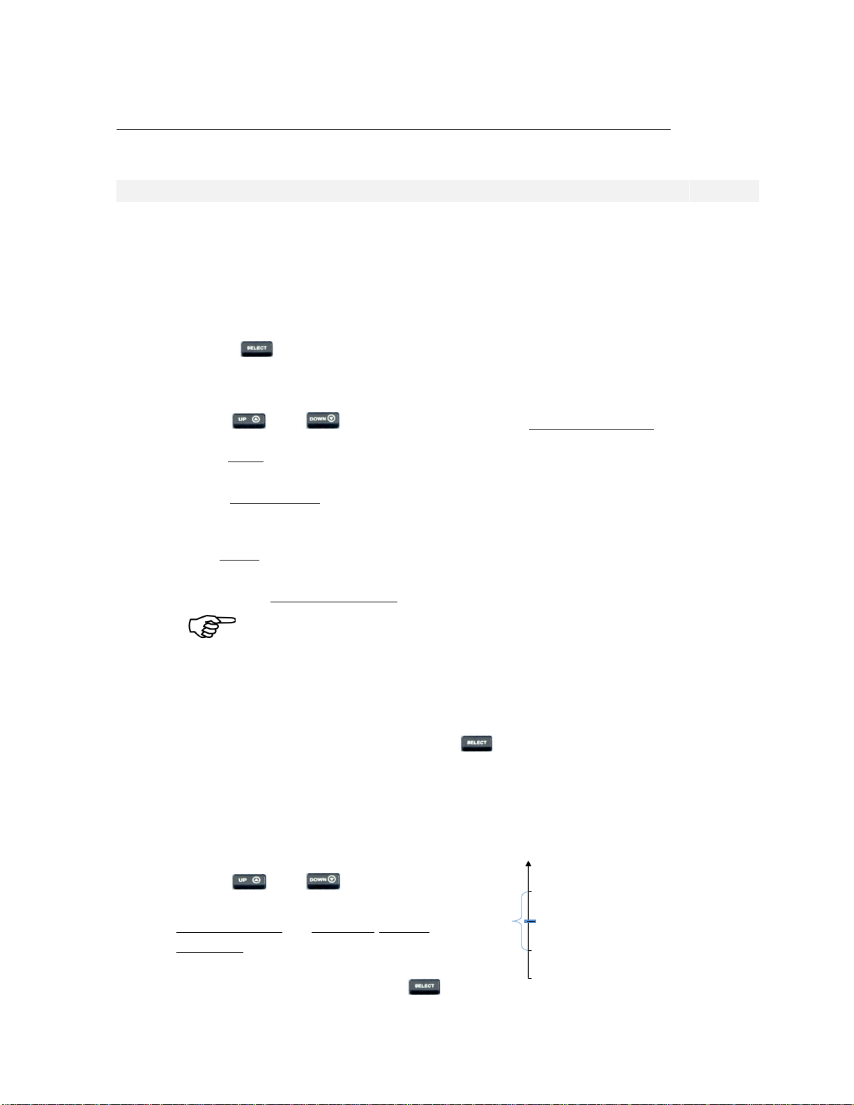
74 Panel Functions
Description of the Working Steps for the Gap Sensor (Transparent Sensor):
A) Start the printer in the Service Mode, compare section 6.32 (necessary for steps in section C).
B) Select the Sensor Type
Punched
Please go to [Sync.Sens.Type ] in the printers menu structure:
Engine\Sync.Menu\Sync.Sens.Type\ select Punched
C) Sensor Current (CV value) adjusting
Please go to Sensor Test and select the subpoint Gap:
Engine\Sensor Test\ select Gap
The currently measured sensor level (contrast) is displayed.
Press the key again, after this 2 values are displayed:
Left VV = curr. measured sensor value (level) Right CV = reference value for sensor current.
CV is modifiable (and has an effect on the VV value).
Use the and keys to set the CV value. Approx. CV value:
Put the liner (not the label) of your material into the sensor.
Increase CV (current) until the sensor measured value (VV level) of the
liner is under 10 %.
After that increase CV (sensor current) by another 3 %.
Load label (with liner) into the sensor.
The measured sensor level (VV Pegel) of label should count
as possible more than 40 %.
If the sensor measured value (VV level) of label is too low, the
CV value should be decreased.
Higher label VV values than 40 % are more advantageous so long
as there is no rising above 10 % of the liner VV level.
Measure both sensor levels once again for Liner and Label.
(You need the two level values of your material for the following switching threshold adjustment)
Save the new current value (CV) using the key.
25 %
+ 3 %
D) Sensor Switching Threshold adjusting
Please go to [Sync.Sens.Level ] in the printers menu structure:
Engine\Sync.Menu\Sync.Sens.Level
At the right the switching threshold value is displayed.
Use the and keys to set the
switching threshold of the sensor to the
middle between the liner level and the
label level:
Save the new switching threshold ( key).
Graphical explanation for switching threshold setting:
Level
in %
Label (with liner)
Mean value is to be used as Switching threshold
Liner
0
_______________________________________________________________________________________________
_______________________________________________________________________________________________
MICROPLEX Operator’s Manual LOGIJET T8-3 Edition 1.0prel
Page 75
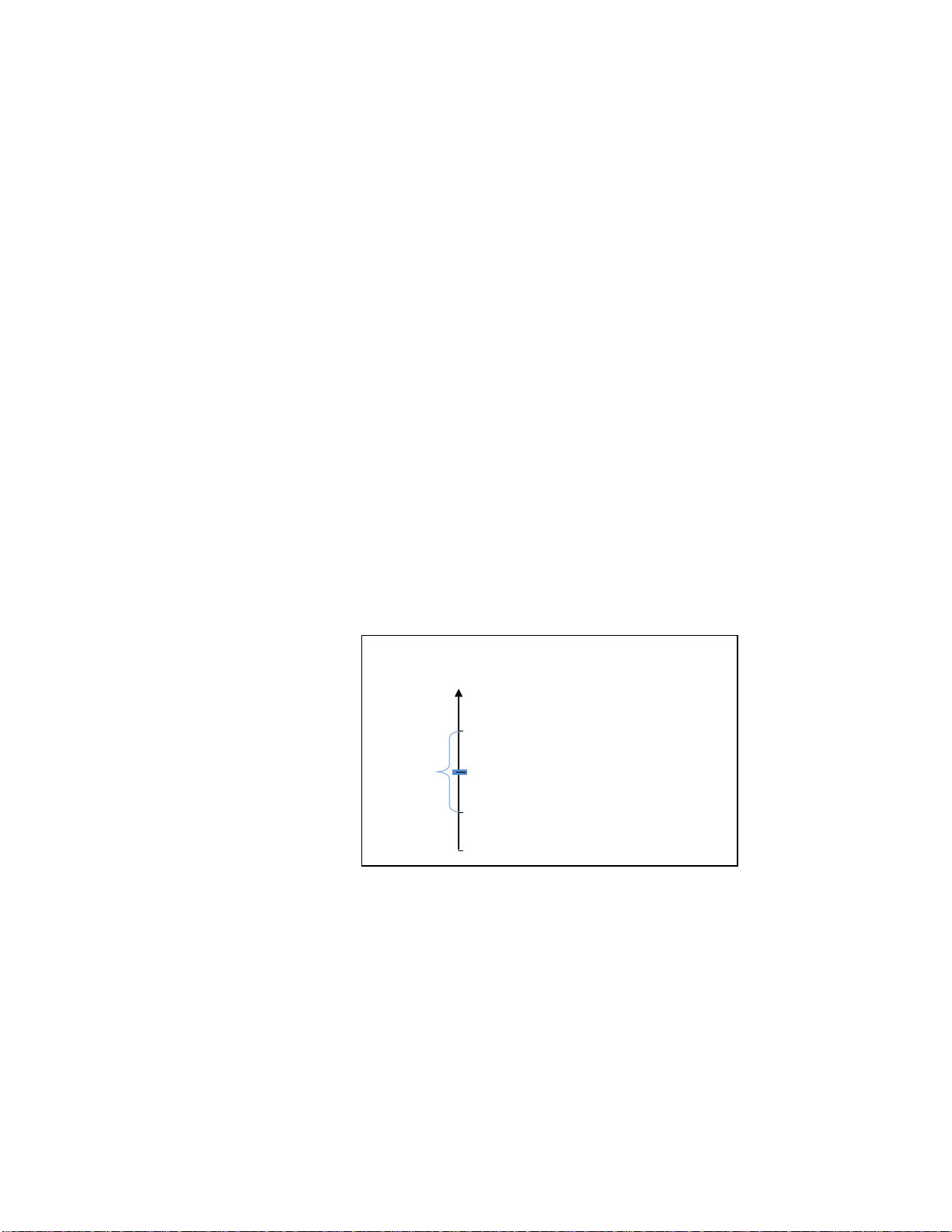
Panel Functions 75
After selecting the panel function Sync.Sens.Level the contrast of
the inserted material (placed in the photoelectric sensor area) is shown
on the printer display. The left level value is the currently
measured sensor value (You’ll find more details in the previous
sections.)
For all different contrast zones of the current material sensor values
(level values in %) have to be measured now. Place the material in the
photoelectric sensor area and read the level values.
Example: Self-adhesive material with black bars across the label
Zone of the inserted material: Sensor measured value (level):
Label + liner + black bar 75 %
Label + liner 44 %
Liner (other names: carrier or backing) 12 %
Calculation of the Switching Threshold
The middle between the label level (incl. liner) and liner level has to
be calculated:
(44% - 12%)/2 + 12% = 28%
In this example the switching threshold is to be set to the value 28 %.
(The steps to set the Sync sensor level at the printer panel can be found
on the following page.)
Graphical explanation for switching threshold setting:
Level
in %
44 Label (with liner)
Mean value is to be used as Switching threshold
12 Liner
0
_______________________________________________________________________________________________
6.1.4.3. Example: Determining the Switching Threshold for a Label Material
_______________________________________________________________________________________________
MICROPLEX Operator’s Manual LOGIJET T8-3 Edition 1.0prel
Page 76
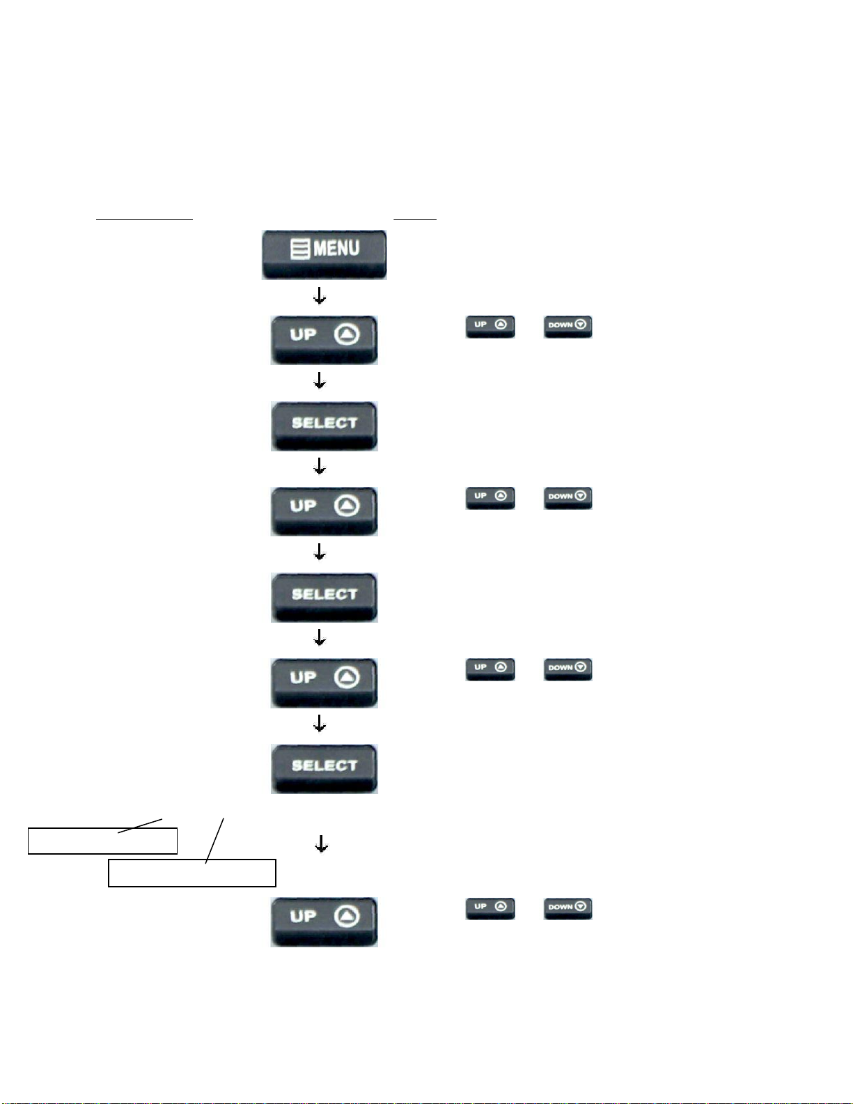
76 Panel Functions
Panel display
Notes
[Online ]
Turn the printer OFF LINE with this key.
[Menu Level 1 ]
. . .
Press the or key until
[Engine ] is displayed.
[Engine ]
Press this key. This selects the Engine menu.
[Printspeed ]
. . .
Press the or key until
[Sync.Menu ] is displayed.
[Sync.Menu ]
Press this key. This selects the Sync menu.
[Sync.Sens.Type ]
Press the or key until
[Sync.Sens.Level ] is displayed.
[Sync.Sens.Level ]
Press this key to adjust the Sync Sensor
level (switching threshold).
[Level: 44% 40%]
At the right the currently set switching
threshold is displayed. (At the left the
sensor measured contrast value is
displayed.)
. . .
Press the or key until the
desired switching threshold is displayed.
Switching Threshold
_______________________________________________________________________________________________
Steps to set the Switching Threshold (Sync.Sens.Level) at the printer panel:
_______________________________________________________________________________________________
MICROPLEX Operator’s Manual LOGIJET T8-3 Edition 1.0prel
Page 77
Panel Functions 77
[Level: 44% 28%]
In this example the switching threshold is
adjusted to 28%.
[Save as Setup? ]
[Online ]
In addition this new value can be saved as
setup value (using the key), before
the printer is turned ON LINE again. After
this decision turn the printer ON LINE
again: Press the key longer than 2
seconds.
_______________________________________________________________________________________________
_______________________________________________________________________________________________
MICROPLEX Operator’s Manual LOGIJET T8-3 Edition 1.0prel
Page 78
78 Panel Functions
This function allows to select the print process.
While thermal direct printing the device operates without ribbon,
direct thermal media is required.
While thermal transfer printing a ribbon is needed to transfer the
print contents onto the media (see chapter 4 Handling of
Consumables, too).
For thermal direct printing it is not allowed to insert a ribbon to
avoid damaging the printhead.
Make sure your settings match to the printer implementation (ribbon
inserted/not inserted).
_______________________________________________________________________________________________
6.2. Print Process Selecting
Description of this control panel function continues on the next page.
_______________________________________________________________________________________________
MICROPLEX Operator’s Manual LOGIJET T8-3 Edition 1.0prel
Page 79
Panel Functions 79
Panel display
Notes
[Online ]
Turn the printer OFF LINE with this key.
[Menu Level 1 ]
. . .
Press the or key until
[Engine ] is displayed.
[Engine ]
Press this key. This selects the Engine menu.
[Printspeed ]
. . .
Press the or key until
[Process ] is displayed.
[Process ]
Press this key to select the process.
[Thermo direct ]
. . .
Press the or key until the
display message is corresponding with the
printer implementation (ribbon inserted =
Thermo transfer e.g.).
[Thermo transfer ]
The thermal transfer print process is selected.
[Save as Setup? ]
[Online ]
In addition this new value can be saved as
setup value (using the key), before
the printer is turned ON LINE again. After
this decision turn the printer ON LINE again:
Press the key longer than 2 seconds.
_______________________________________________________________________________________________
_______________________________________________________________________________________________
MICROPLEX Operator’s Manual LOGIJET T8-3 Edition 1.0prel
Page 80
80 Panel Functions
This function is used to adjust the printer to the unwinding direction of
your ribbon (distinction between ink inside and ink outside).
Note: More details are described in section 4.2.1 Ribbon Loading.
Panel display
Notes
[Online ]
Turn the printer OFF LINE with this key.
[Menu Level 1 ]
. . .
Press the or key until [Engine ] is
displayed.
[Engine ]
Press this key. This selects the Engine menu.
[Printspeed ]
. . .
Press the or key until
[Ribbon Unwinding] is displayed.
[Ribbon Unwinding]
Press this key to select the Ribbon Unwinding
submenu.
[Ink outside ]
. . .
Press the or key until the display
message is corresponding with the unwinding
direction of your ribbon.
[Ink inside ]
The ribbon unwinding direction for ink inside is
selected.
[Save as Setup? ]
[Online ]
In addition this new value can be saved as setup
value (using the key), before the printer is
turned ON LINE again. After this decision turn the
printer ON LINE again: Press the key
longer than 2 seconds.
_______________________________________________________________________________________________
6.3. Ribbon Unwinding Setting (Ink Inside or Outside)
_______________________________________________________________________________________________
MICROPLEX Operator’s Manual LOGIJET T8-3 Edition 1.0prel
Page 81
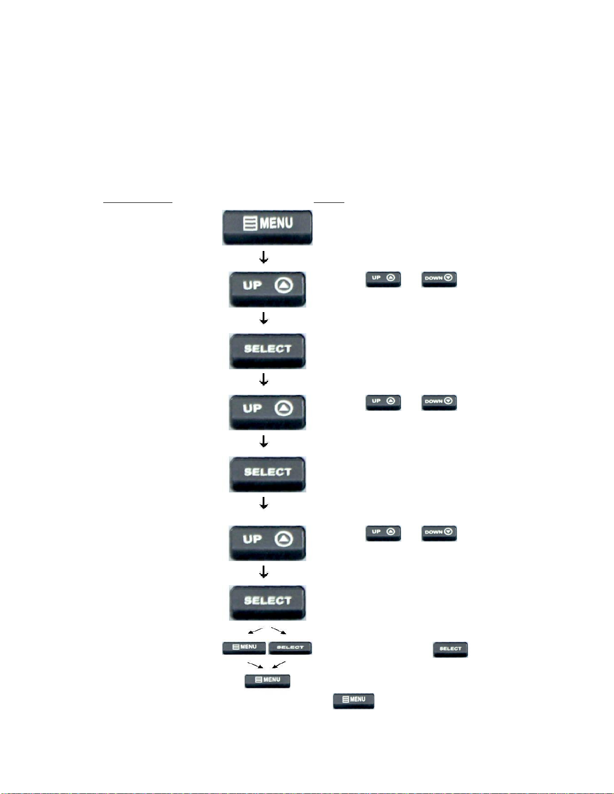
Panel Functions 81
This function allows to adjust the printer to the actual used material
(distinction between formatted media (label) and continuous media).
Note: You have to adjust the Sync sensors to your media first. (See previous
sections).
Panel display
Notes
[Online ]
Turn the printer OFF LINE with this key.
[Menu Level 1 ]
. . .
Press the or key until
[Paper Menu ] is displayed.
[Paper Menu ]
Press this key. This selects the Paper menu.
[Paper Size ]
. . .
Press the or key until [Material ]
is displayed.
[Material ]
Press this key. This selects the Material submenu.
[Label ]
The currently set value is displayed.
. . .
Press the or key until the
statement shown by the display corresponds to
the inserted media (Continuous e.g.).
[Continuous ]
The printer is adjusted to continuous material.
[Save as Setup? ]
[Online ]
In addition this new value can be saved as
setup value (using the key), before the
printer is turned ON LINE again. After this
decision turn the printer ON LINE again: Press
the key longer than 2 seconds.
_______________________________________________________________________________________________
6.4. Media Setting (Material; Label or Continuous)
_______________________________________________________________________________________________
MICROPLEX Operator’s Manual LOGIJET T8-3 Edition 1.0prel
Page 82
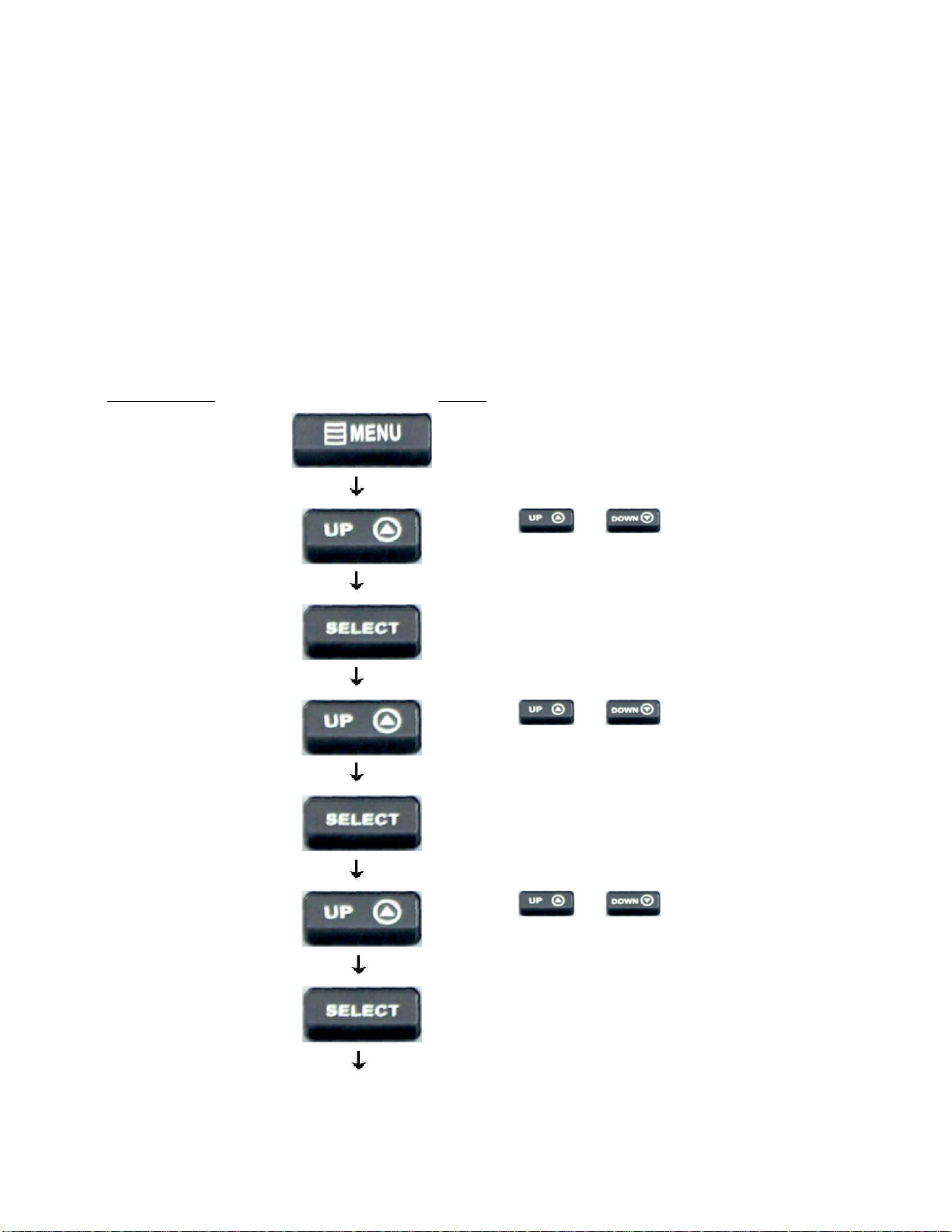
82 Panel Functions
Using this function an offset from the detected paper feed zeroposition can be set. (See figure next page) By this the position of
printout and tear off/cut is adjusted relatively to the
material. (TOF, offset from the printer-detected punch position, that
means relatively to the gap/perforation and start of the label. The
setting range for the offset is approximately ± 20 mm.
Note: You should execute this offset adjusting after having adjusted the Sync
sensors successfully (see previous sections).
Panel display
Notes
[Online ]
Turn the printer OFF LINE with this key.
[Menu Level 1 ]
. . .
Press the or key until
[Engine ] is displayed.
[Engine ]
Press this key. This selects the Engine
menu.
[Printspeed ]
. . .
Press the or key until
[Sync.Menu ] is displayed.
[Sync.Menu ]
Press this key. This selects the Sync menu.
[Sync.Sens.Type ]
. . .
Press the or key until
[Sync.Sens.Offset] is displayed.
[Sync.Sens.Offset]
[Offset: +0.0 mm ]
The currently set offset value is displayed.
_______________________________________________________________________________________________
6.5. Adjusting the Zero Position of the Material Transport (Sync.Sens.Offset) )
_______________________________________________________________________________________________
MICROPLEX Operator’s Manual LOGIJET T8-3 Edition 1.0prel
Page 83
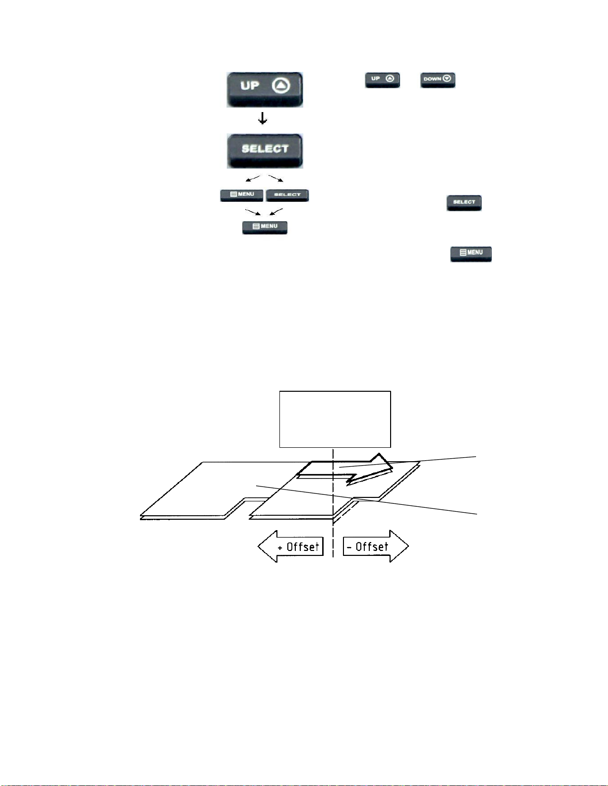
Panel Functions 83
. . .
Press the or key until the
desired offset is displayed.
[Offset: +1.0 mm ]
The gap position is shifted 1 mm against
the feed direction .
[Save as Setup? ]
[Online ]
In addition this new value can be saved
as setup value (using the key),
before the printer is turned ON LINE
again. After this decision turn the printer
ON LINE again: Press the key
longer than 2 seconds.
feed direction
print material
Gap position
detected by
the printer,
zero-position
_______________________________________________________________________________________________
Fig. 6.5.a Setting the zero position of the material feed
_______________________________________________________________________________________________
MICROPLEX Operator’s Manual LOGIJET T8-3 Edition 1.0prel
Page 84
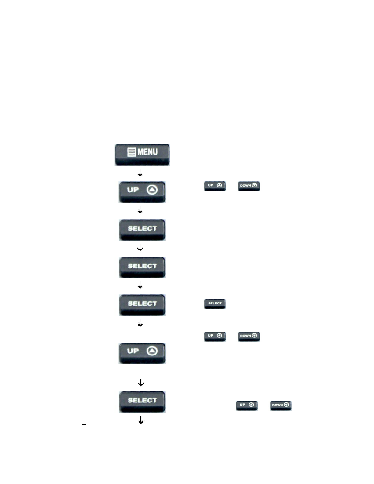
84 Panel Functions
After inserting new material (e.g. paper) this function is used to adjust
the printer to the new page length.
Hint: Alternatively, the printer itself is able to measure the label length. See
next sections.
Panel display
Notes
[Online ]
Turn the printer OFF LINE with this key.
[Menu Level 1 ]
. . .
Press the or key until
[Paper Menu ] is displayed.
[Paper Menu ]
Press this key. This selects the Paper menu.
[Paper Size ]
Press this key. This selects the Paper Size menu.
[Page Length ]
Press the key to adjust the page length.
[Measure Length ]
. . .
Press the or key if you want to
adjust the page length manually:
[in mm ]
mm = currently selected measuring unit.
(Alternative the units inch or 1/300 inch can
be chosen with the or key).
[Digit4 149.9 ]
The currently set page length is displayed.
_______________________________________________________________________________________________
6.6. Page Length Adjustment
_______________________________________________________________________________________________
MICROPLEX Operator’s Manual LOGIJET T8-3 Edition 1.0prel
Page 85
Panel Functions 85
. . .
Pressing the or key changes the
value of the current digit (Digit4 = left position,
in this example: 1). Pressing the key
moves you to the next digit (the key
moves you back, if need be).
[Digit1 149.5 ]
The page length is changed to 149.5 mm.
[Perm.Speichern? ]
[Online ]
In addition this new value can be saved as
setup value (using the key), before the
printer is turned ON LINE again. After this
decision turn the printer ON LINE again: Press
the key longer than 2 seconds.
_______________________________________________________________________________________________
_______________________________________________________________________________________________
MICROPLEX Operator’s Manual LOGIJET T8-3 Edition 1.0prel
Page 86
86 Panel Functions
_______________________________________________________________________________________________
6.6.1. Starting the (Printer’s) Measurement of Label Length
Use the panel function
Paper Menu \ Paper Size \ Page Length \ Measure Length
The printer performs a material feed and reports the measured label length on
the display.
Use the key to confirm this value (configuration of the measured
label length).
In addition this new value can be saved permanent as setup value (using the
key, again).
6.6.2. Configuration of Semiautomatic Label Length Measurement
The panel function
Paper Menu \ Paper Size \ Page Length \ Auto.Measurement
serves to switch the semiautomatic label length measurement function to on or
off (and to save this setting as setup value).
If the semiautomatic label length measurement function is chosen, the printer
automatically offers you the measurement of the label length after
every printer power on and after every closing of the printhead (for
example after the inserting of a new label roll):
Panel display [Measure length ]
Use the key to start the measurement of label length, use the
key to suppress this function.
The printer saves the measured label length temporal (as long as the printer
stays turned on).
_______________________________________________________________________________________________
MICROPLEX Operator’s Manual LOGIJET T8-3 Edition 1.0prel
Page 87
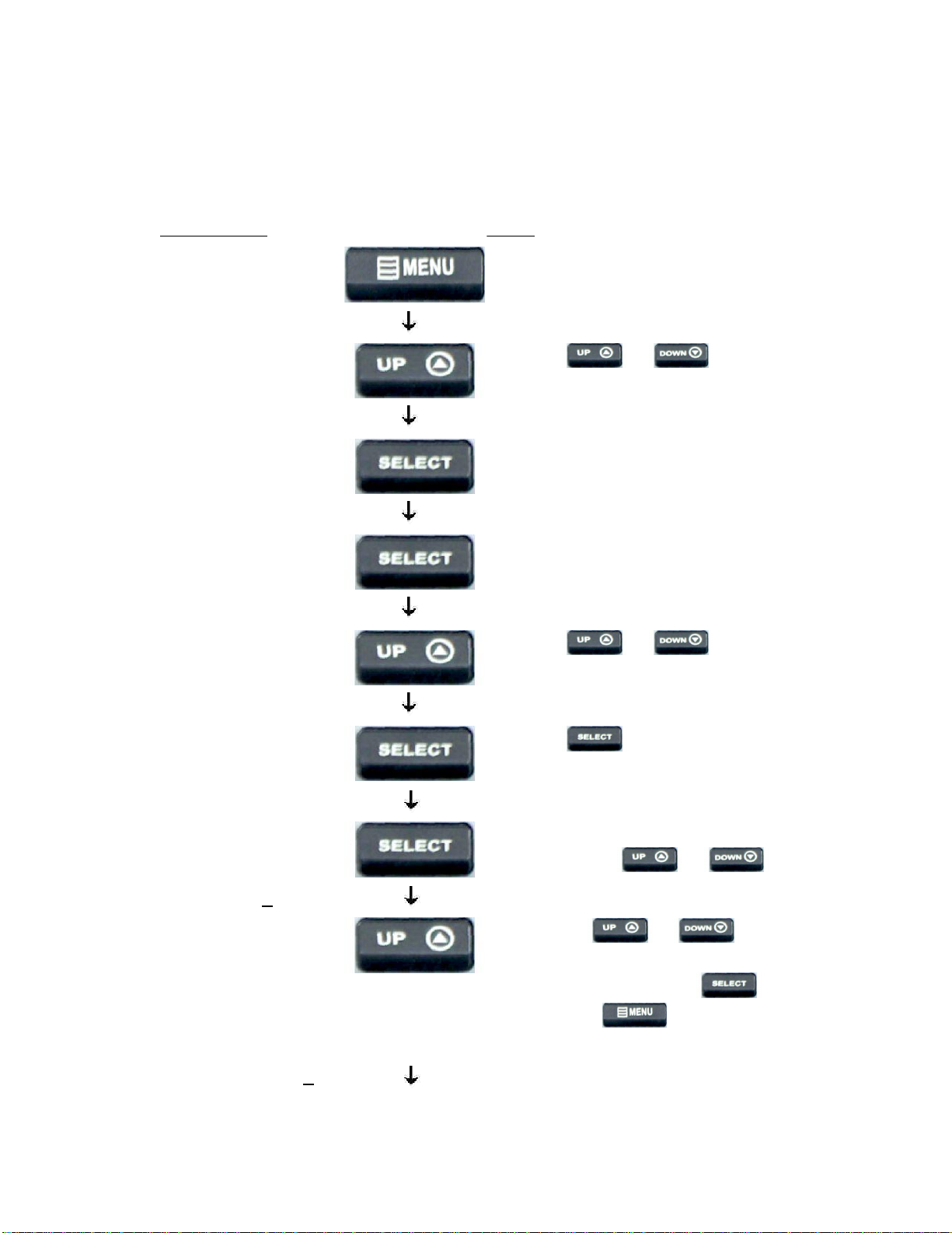
Panel Functions 87
The paper width (print width) has to be adjusted with this function
according to the currently used format.
Panel display
Notes
[Online ]
Turn the printer OFF LINE with this key.
[Menu Level 1 ]
. . .
Press the or key until [Paper Menu ] is
displayed.
[Paper Menu ]
Press this key. This selects the Paper menu.
[Paper Size ]
Press this key. This selects the Paper Size menu.
[Page Length ]
. . .
Press the or key until [Paper Width ] is
displayed.
[Paper Width ]
. . .
Press the key to adjust the format width to the
paper width.
[in mm ]
mm = currently selected measuring unit.
(Alternative the units inch or 1/300 inch can be
chosen with the or key).
[Digit4 108.4 ]
The currently set paper width is displayed.
. . .
Pressing the or key changes the value
of the current digit (Digit4 = left position, in this
example: 1). Pressing the key moves you to the
next digit (the key moves you back, if need
be).
[Digit1 108.0 ]
_______________________________________________________________________________________________
6.7. Material Width Adjustment (Paper Width)
_______________________________________________________________________________________________
MICROPLEX Operator’s Manual LOGIJET T8-3 Edition 1.0prel
Page 88

88 Panel Functions
The format width (paper width) is changed to 108.0
mm.
[Save as Setup? ]
[Online ]
In addition this new value can be saved as setup value
(using the key), before the printer is turned ON
LINE again. After this decision turn the printer ON
LINE again: Press the key longer than 2
seconds.
_______________________________________________________________________________________________
_______________________________________________________________________________________________
MICROPLEX Operator’s Manual LOGIJET T8-3 Edition 1.0prel
Page 89
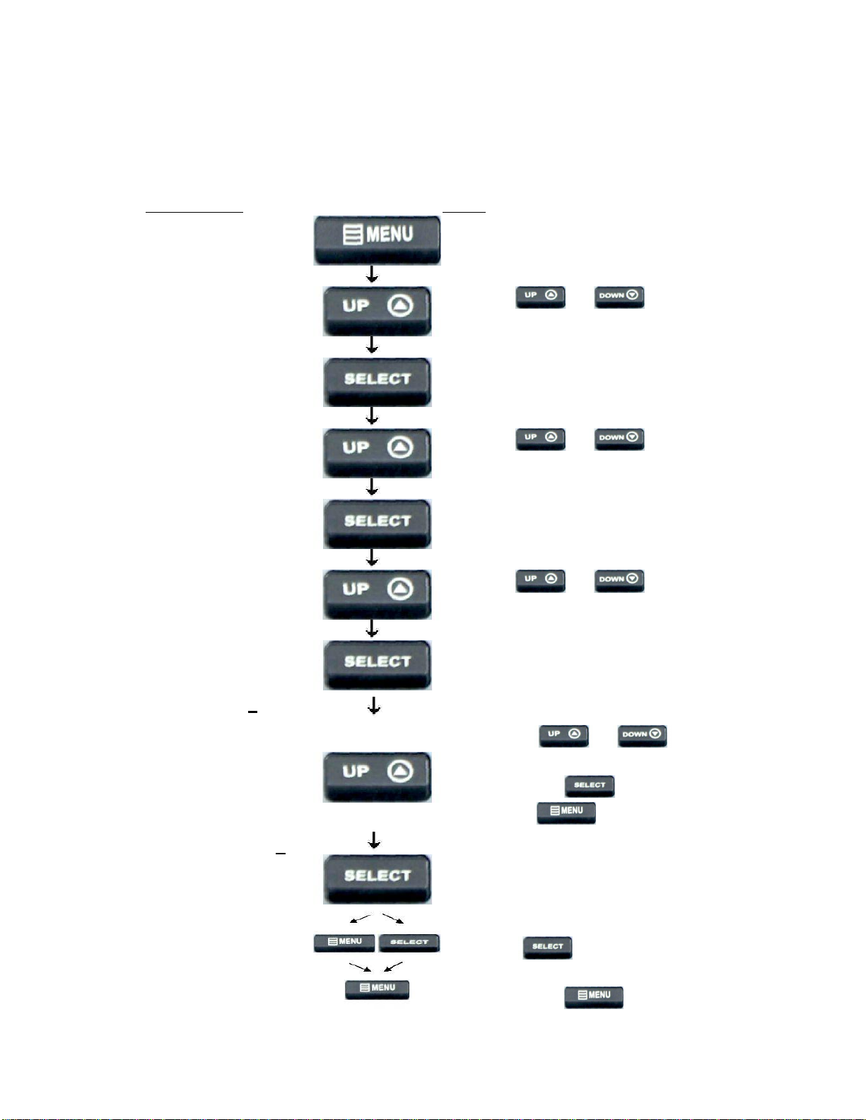
Panel Functions 89
This function sets text margins. Margins are expressed in dots at the
concerning edge of the paper.
Panel display
Notes
[Online ]
Turn the printer OFF LINE with this key.
[Menu Level 1 ]
. . .
Press the or key until [Page Menu ] is
displayed.
[Page Menu ]
Betätigen Sie diese Taste, dadurch wird das
Konfigurationsmenü gewählt.
[Font Number ]
. . .
Press the or key until [Margin ] is
displayed.
[Margin ]
Press this key. This selects the Margin configuration
menu.
[Left ]
. . .
Press the or key until the desired margin
is displayed.
[from Right ]
Press this key if you want to configure the right margin.
[Digit4 0081 ]
The currently set value is displayed.
. . .
Pressing the or key changes the value of
the current digit. (Digit 4 = left position, in this example:
0). Pressing the key moves you to the next
position (the key moves you back, if need be).
[Digit1 0087 ]
The right margin is changed to 87 dot.
[Save as Setup? ]
[Online ]
In addition this new value can be saved as setup value
(using the key), before the printer is turned ON
LINE again. After this decision turn the printer ON LINE
again: Press the key longer than 2 seconds.
_______________________________________________________________________________________________
6.8. Configuration of Text Margins
_______________________________________________________________________________________________
MICROPLEX Operator’s Manual LOGIJET T8-3 Edition 1.0prel
Page 90
90 Panel Functions
This function generates a status sheet. The status sheet contains
information about the current printer configuration, the
available fonts and options.
Panel display
Notes
[Online ]
Turn the printer OFF LINE with this key.
[Menu Level 1 ]
Press this key. Menu Level 1 is selected.
[Status Sheet ]
Press this key again.
[Status Sheet ]
A status sheet is printed.
Turn the printer ON LINE again: Press the
key longer than 2 seconds. After this
the printer is ready to print again.
[Online ]
_______________________________________________________________________________________________
6.9. Printing the Status Sheet
_______________________________________________________________________________________________
MICROPLEX Operator’s Manual LOGIJET T8-3 Edition 1.0prel
Page 91

Panel Functions 91
-
-
-
-
-
-
-
-
-
-
-
-
-
The first lines, entitled SERVICE INFORMATION, contain
hexadecimal coded configuration parameters.
Printed in plain text:
Controller version / memory / serial number
Firmware release
Interface
parameters of Parallel, USB, Network (Ethernet)
Network
parameters and addresses
Printer emulation
User-RAM / free User-RAM
Input data buffer
Transparent code
Paper size
Default margins top / left
bottom / right
Default character code
Options
Fonts installed (Font banks)
_______________________________________________________________________________________________
Status sheet contents:
Note: Use the panel function Printing the Font List to show the fonts installed
(see the following section).
_______________________________________________________________________________________________
MICROPLEX Operator’s Manual LOGIJET T8-3 Edition 1.0prel
Page 92
92 Panel Functions
This function generates a list of all fonts installed to the printer.
The font list shows demo prints of all fonts and, in addition, the
concerning PCL selection commands. These commands contain
information on font width and font hight (see panel function
Font Selection, too).
Panel display
Notes
[Online ]
Turn the printer OFF LINE with this key.
[Menu Level 1 ]
Press this key. Menu Level 1 is selected.
[Status Sheet ]
. . .
Press the or key until
[Font List ] is displayed.
[Font List ]
The font list is printed.
[Font List ]
[Online ]
Turn the printer ON LINE again: press the
key longer than 2 seconds. After this
the printer is ready to print again.
_______________________________________________________________________________________________
6.10. Printing the Font List
_______________________________________________________________________________________________
MICROPLEX Operator’s Manual LOGIJET T8-3 Edition 1.0prel
Page 93
Panel Functions 93
In the Hexdump Mode the printer prints all characters
received via interface without any interpretation (hexadecimal
coded).
This mode helps with error diagnosis. The Hexdump Mode
can be activated only temporarily.
Panel display
Notes
[Online ]
Turn the printer OFF LINE with this key.
[Menu Level 1 ]
Press this key. Menu Level 1 is selected.
[Status Sheet ]
. . .
Press the or key until
[Hexdump ] is displayed.
[Hexdump ]
The Hexdump Mode is activated.
[Hexdump ]
[Online ]
Turn the printer ON LINE again: Press the
key longer than 2 seconds. After
this the printer is ready to print again.
Note: By activating the normal print mode (see next page) or by turning the printer
off and on again the printer can be taken out of Hexdump Mode. Time
between turning the printer off and on again should be at least 15 seconds.
_______________________________________________________________________________________________
6.11. Hexdump Mode Activation
_______________________________________________________________________________________________
MICROPLEX Operator’s Manual LOGIJET T8-3 Edition 1.0prel
Page 94
94 Panel Functions
The normal print mode suspends the Hexdump Mode. This
function is activated, when a print job must be continued
without turning the printer off and on again.
In addition to that the function “Normal Print Mode
Activation“ is used to produce a FORM FEED.
Panel display
Notes
[Online ]
Turn the printer OFF LINE with this key.
[Menu Level 1 ]
Press this key. Menu Level 1is selected.
[Status Sheet ]
. . .
Press the or key until
[Normal Print/FF ] is displayed.
[Normal Print/FF ]
The normal print mode is activated.
[Normal Print/FF ]
[Online ]
Turn the printer ON LINE again: Press
the key longer than 2
seconds.
Note: After activating the normal print mode a FORM FEED is released
automatically and one sheet is put out. This is necessary because after a
test in the Hexdump Mode it is possible that data can remain in the input
buffer unintentionally. (Cause: in the Hexdump Mode no control
characters are evaluated and no FORM FEED is effected).
_______________________________________________________________________________________________
6.12. Normal Print Mode Activation (incl. FORM FEED)
_______________________________________________________________________________________________
MICROPLEX Operator’s Manual LOGIJET T8-3 Edition 1.0prel
Page 95
Panel Functions 95
This function permits the resumption of a print job at a
particular page after a print interruption (e.g. paper jam). The
data contained in the input buffer before the interruption are
cleared.
Panel display
Notes
[Online ]
Turn the printer OFF LINE with this key.
[Menu Level 1 ]
Press this key. Menu Level 1 is selected.
[Status Sheet ]
. . .
Press the or key until
[Cancel Job ] is displayed.
[Cancel Job ]
All data contained in the input buffer will be
cleared.
[Cancel Job ]
[Online ]
Turn the printer ON LINE again: Press the
key longer than 2 seconds.
_______________________________________________________________________________________________
6.13. Clearing the Input Buffer (Cancel Job)
_______________________________________________________________________________________________
MICROPLEX Operator’s Manual LOGIJET T8-3 Edition 1.0prel
Page 96
96 Panel Functions
This function prints a survey of the available panel functions.
Note: When printing the menu page please use a large
paper.
Panel display
Notes
[Online ]
Turn the printer OFF LINE with this key.
[Menu Level 1 ]
Press this key. This selects Menu Level 1.
[Status Sheet ]
. . .
Press the or key until
[Menu Page ] is displayed.
[Menu Page ]
A menu structure presentation of the printer is
printed (compare diagram in section Menu
Structure).
[Menu Page ]
[Online ]
Turn the printer ON LINE again: Press the
key longer than 2 seconds. After this
the printer is ready to print again.
_______________________________________________________________________________________________
6.14. Printing the Menu Page
_______________________________________________________________________________________________
MICROPLEX Operator’s Manual LOGIJET T8-3 Edition 1.0prel
Page 97
Panel Functions 97
This function generates a series of test prints without
sending data to the printer.
These test prints facilitate error analysis.
Panel display
Notes
[Online ]
Turn the printer OFF LINE with this
key.
[Menu Level 1 ]
Press the or key until
[Page Menu ] is displayed.
[Status Sheet ]
. . .
Press the or key until
[Sliding Pattern ] is displayed.
[Sliding Pattern ]
A series of test prints is generated.
[Sliding Pattern ]
[Online ]
Turn the printer ON LINE again:
Press the key longer than 2
seconds.
The printing out of test prints can be stopped by pressing
the key.
_______________________________________________________________________________________________
6.15. Generating Testsheets (Sliding Pattern)
_______________________________________________________________________________________________
MICROPLEX Operator’s Manual LOGIJET T8-3 Edition 1.0prel
Page 98
98 Panel Functions
This function selects the active print orientation (orientation of the whole
printout including graphics, etc. on the paper).
Panel display
Notes
[Online ]
Turn the printer OFF LINE with this key.
[Menu Level 1 ]
. . .
Press the or key until
[Paper Menu ] is displayed.
[Paper Menu ]
Press this key. The Paper Menu is selected.
[Paper Size ]
. . .
Press the or key until
[Print Direct. ] is displayed.
[Print Direct. ]
Press this key. The Print Direction menu is
selected.
[Print Direct. 0 ]
The currently set print direction is displayed.
. . .
Press the or key until the
desired print direction is displayed.
[Print Direct. 1 ]
The print direction 1 = landscape is selected.
[Save as Setup? ]
In addition this new value can be saved as
setup value (using the key), before
the printer is turned ON LINE again. After
this decision turn the printer ON LINE again:
Press the key longer than 2 seconds.
[Online ]
Print direction assignment:
Print direction 0 = Portrait (upright format)
Print direction 1 = Landscape (horizontal format)
Print direction 2 = Portrait upside down
Print direction 3 = Landscape upside down
_______________________________________________________________________________________________
6.16. Print Direction Selection
_______________________________________________________________________________________________
MICROPLEX Operator’s Manual LOGIJET T8-3 Edition 1.0prel
Page 99
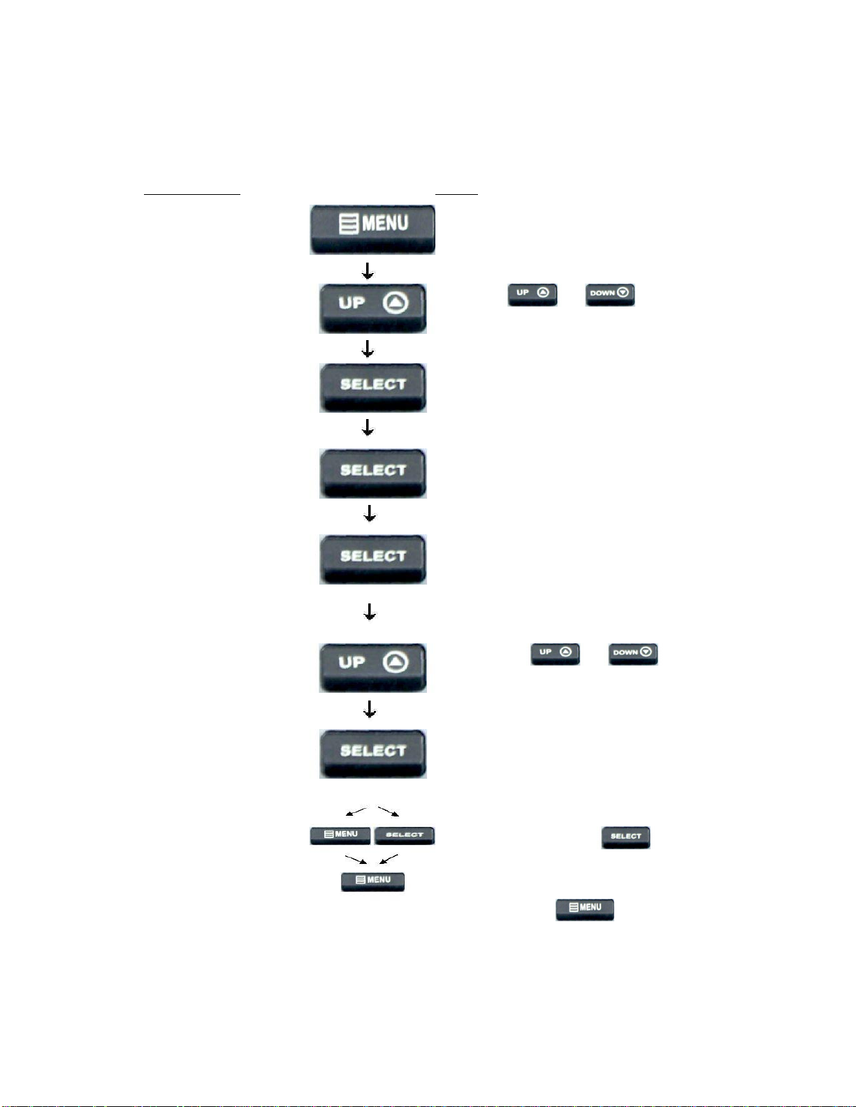
Panel Functions 99
This function is used to set the interface parameters.
Panel display
Notes
[Online ]
Turn the printer OFF LINE with this key.
[Menu Level 1 ]
. . .
Press the or key until
[Configuration ] is displayed.
[Configuration ]
Press this key. This selects the Configuration
menu.
[Interface ]
Press this key. This selects the Interface
menu.
[SIA Timeout ]
Press this key. This selects the Timeout
menu.
[ 30 s ]
The currently set value for the timeout is
displayed (here: 30 seconds).
. . .
Pressing the or key changes
the timeout value.
[ 40 s ]
The timeout (the waiting period for SIA to
switch to the next interface) is increased to
40 seconds.
[Save as Setup? ]
In addition this new value can be saved as
setup value (using the key), before
the printer is turned ON LINE again. After
this decision turn the printer ON LINE
again: Press the key longer than 2
seconds.
[Online ]
Note:
The printer uses SIA (Simultaneous Interface Administration) to check, which
interface is currently used for the transfer of print data.
_______________________________________________________________________________________________
6.17. Data Interface Configuration
_______________________________________________________________________________________________
MICROPLEX Operator’s Manual LOGIJET T8-3 Edition 1.0prel
Page 100
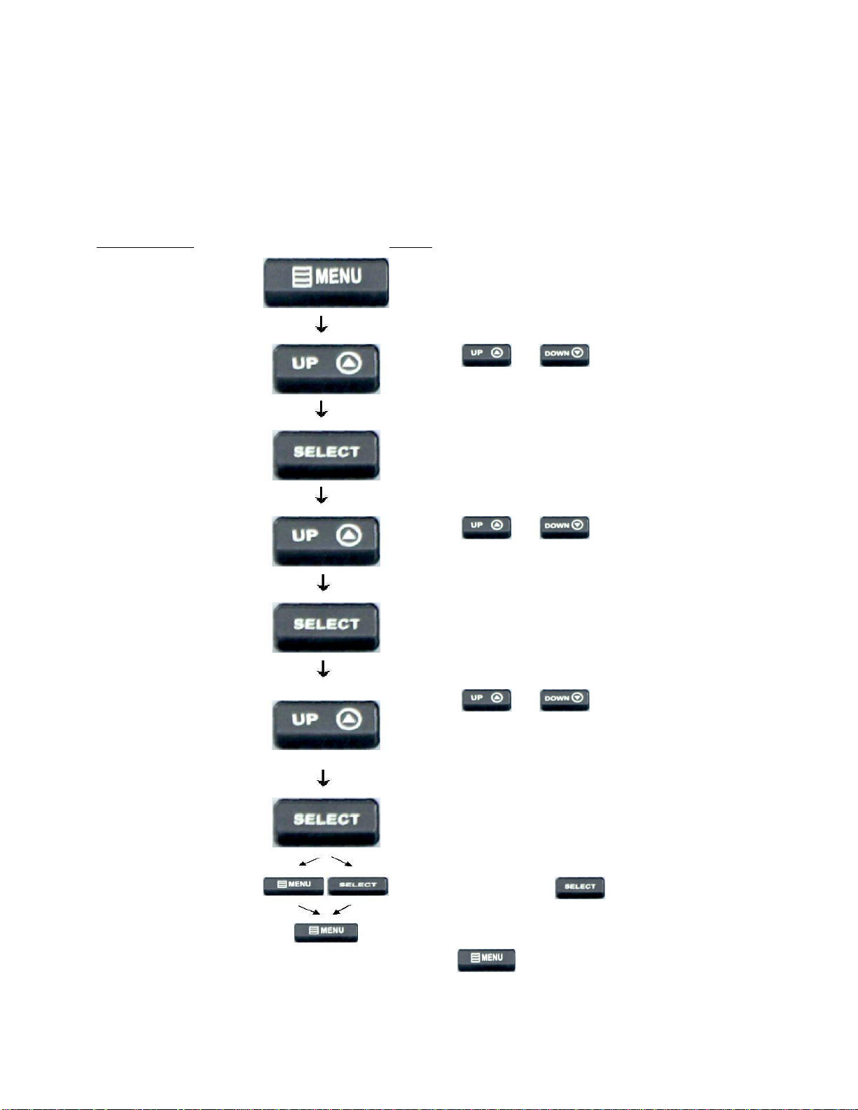
100 Panel Functions
This function helps to determine which printer emulation will
be activated.
Panel display
Notes
[Online ]
Turn the printer OFF LINE with this key.
[Menu Level 1 ]
. . .
Press the or key until
[Configuration ] is displayed.
[Configuration ]
Press this key. This selects the Configuration
menu.
[Interface ]
. . .
Press the or key until
[Emulation ] is displayed.
[Emulation ]
Press this key. This selects the Emulation
menu.
[SOLID Standard ]
. . .
Press the or key until the
desired emulation (e.g. HP PCL 5) is
displayed.
[HP PCL 5 ]
The emulation HP PCL 5 is selected.
[Save as Setup? ]
In addition this new value can be saved as
setup value (using the key), before
the printer is turned ON LINE again. After
this decision turn the printer ON LINE again:
Press the key longer than 2 seconds.
[Online ]
_______________________________________________________________________________________________
6.18. Emulation Selection
_______________________________________________________________________________________________
MICROPLEX Operator’s Manual LOGIJET T8-3 Edition 1.0prel
 Loading...