

Page 1
TURBOFAN
Instruction manual and
installation guide
Micron Sprayers Limited
Bromyard Industrial Estate
Bromyard, Herefordshire
HR7 4HS, UK
Tel: +44 (0) 1885 482397
Fax:+44 (0) 1885 483043
E-mail: micron@micron.co.uk
URL: http://www.micron.co.uk
Page 2

DRAFT
CONTENTS
SECTION PAGE NUMBER
1.0 INTRODUCTION 2
2.0 SPECIFICATION
3.0 TEN KEY POINTS FOR USERS
4.0 INSTALLATION
4.1 Mounting of Sprayheads 5
4.2 Hydraulic System 7
4.3 Spray liquid 15
4.4 Testing 17
3
4
5
5.0 OPERATION 17
5.1 Daily Inspection 17
5.2 Calibration Procedure 17
5.3 Position of Sprayheads 17
5.4 Sequence of Operation 18
5.5 After Use 18
6.0 HEALTH AND SAFETY 18
7.0 CALIBRATION AND ADJUSTMENT
7.1 Application Rate 19
19
8.0 MAINTENANCE 23
8.1 Routine Maintenance 23
8.2 Dismantling of Sprayhead 23
9.0 PARTS LIST AND DIAGRAM 25
1
Page 3

DRAFT
1.0 INTRODUCTION
The Micron TURBOFAN Sprayhead has been developed from over 30 years experience
in the design and use of rotary atomisers. Originally developed for agricultural aircraft,
these atomisers are now used for aerial and ground applications in more than 75 countries. This unique background, combined with continuous research and development, has
enabled Micron to produce a truly versatile and reliable sprayhead for almost every agricultural spraying requirement.
The Micron TURBOFAN sprayhead uses a rotary atomiser, mounted in a protective cowl
and driven by a compact hydraulic motor. The atomiser uses a stack of toothed discs to
break the spray liquid into precise oversized droplets. This unique approach ensures that
all of the spray volume is concentrated into a narrow range of droplet sizes.
The atomiser also incorporates an axial fan which produces a turbulent, swirling airstream from the sprayhead. This carries spray to the target, disturbs foliage and ensures
good penetration to give an even coverage in dense crops.
The Micron TURBOFAN Sprayhead operates over a wide range of liquid flow rates,
enabling the same unit to be used for ultra low, low and higher volume application. The
atomiser is designed to handle all types of liquid formulations from specialised ULV
products to high concentrations of emulsifiable concentrates and solids in suspension.
The Micron TURBOFAN Sprayhead is ideally suited to most spraying tasks, whether in
fields, bushes, orchards or vines. Whatever the application, the combination of controlled droplet size, wide range of application rates and air assistance will enable the user
to achieve improved spray coverage and control with a minimum wastage of chemical,
thus ensuring the best possible biological results at a minimum cost.
Should field service be necessary, the simple design of the sprayhead enables it to be dismantled and cleaned in minutes.
TURBOFAN sprayheads require a hydraulic oil supply to operate. This can often be provided by the tractor or vehicle’s own hydraulic system. Alternatively, it may be necessary to install an auxiliary hydraulic system with its own reservoir and power driven hydraulic pump.
Because of their versatility, TURBOFAN Sprayheads can be installed on a wide range of
sprayers. These may be specially built or may be conversions of existing machines.
Through its own experience and that of its customers, Micron can advise Original Equipment Manufacturers (OEMs) on the design and construction of most types of sprayers.
2
Page 4
DRAFT
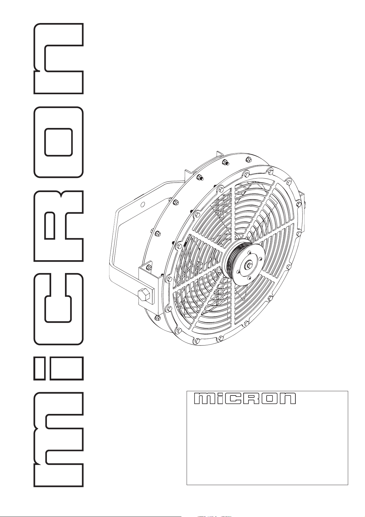
2.0 SPECIFICATION
Length (max. front to back): 35 cm (complete with mounting bracket)
Diameter: 45 cm
Weight: 6.4 Kg plus mounting bracket 1.7 Kg
Liquid flow rate: 0.25 – 2.0 l/min
Spray droplet size: 100 – 120 microns VMD
Hydraulic oil flow: 8 l/min per sprayhead.
Hydraulic pressure: 124 Bar pressure drop across each motor (approx.)
Fan/atomiser speed 4000 rpm
Hydraulic motor supply port: 3/8 BSP (F)
Hydraulic motor return port: 3/8 BSP (F)
Hydraulic motor drain port: 1/8 BSP (F)
Airflow @ 0.4 m (16 in): 98 m³/min/head (3460 ft³/min)
Air velocity @ 0.4 m (16in): 18 m/sec (40.2 mph)
AXIAL FAN
ATOMISER
SAFETY GUAR DS
MO UNTING BRACKET
HYDR AULIC MOTO R
Figure 1. Turbofan spray head
3
Page 5

DRAFT
3.0 TEN KEY POINTS FOR USERS
The following list of ten points is intended to assist users in the efficient use of Turbofan
sprayheads. It is hoped that this section will encourage users to read the entire handbook
and follow its recommendations.
1. Check that all atomisers rotate freely. The only friction should be drag from the hydraulic motor. If binding or roughness is felt, remove the unit as described in Section
8.2 (‘Maintenance, Dismantling of Sprayhead and Atomiser’ ) and inspect the bearing, motor, etc.
2. Check that each atomiser securing screw (Page 25, Item no 7, Micron part no 5983) is
secure.
3. Check that the atomiser discs are free of damage, blockage by dried chemical or any
condition which could cause them to run out of balance.
4. Check that the fan blades are not damaged or out of balance.
5. Ensure that the hydraulic system is filled with oil, is correctly adjusted and that all
atomisers are rotating at the correct speed.
6. Check that the correct flow restrictor orifices are fitted.
7. Ensure that all atomisers are correctly positioned on the boom or support structure
and that they are the correct distance from the target being sprayed.
8. Inspect the entire sprayer for damaged or twisted hoses and ensure that there are no
leaks in the hydraulic or chemical systems.
9. Whilst spraying, verify the accuracy of the calibration of the sprayer by checking the
volume of chemical used against the area sprayed.
10. After use, always flush out the entire system with clean water or a suitable solvent.
Never leave chemical residues in the sprayheads, tank or pipework. Wash off the
outer surfaces of sprayheads, booms, etc with a pressure washer or similar to avoid
build up of pesticide residues.
4
Page 6
DRAFT
4.0 INSTALLATION
The design of a sprayer incorporating Turbofan Sprayheads will vary according to the
crop to be sprayed, the type of sprayer being used and the available hydraulic power.
This section gives general advice and design data but is not intended to provide specific
instructions for building every type of sprayer. Original Equipment Manufacturers
(OEMs) should contact Micron if they require any further information for a particular
application.
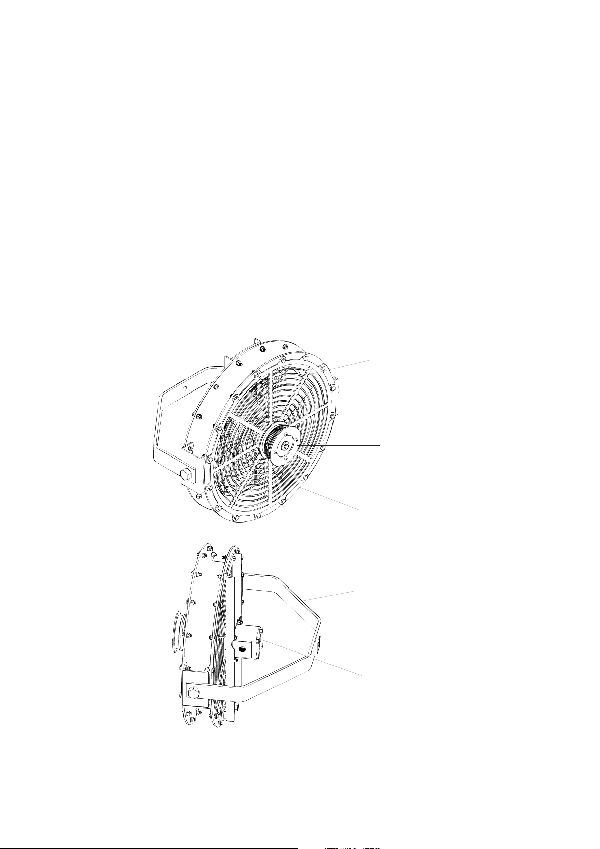
4.1 Mounting of Sprayheads
The configuration of a sprayer and mounting of sprayheads will depend upon the type
and planting of the crop to be sprayed. Some examples of typical configurations are
shown in Figures 2, 3 and 4.
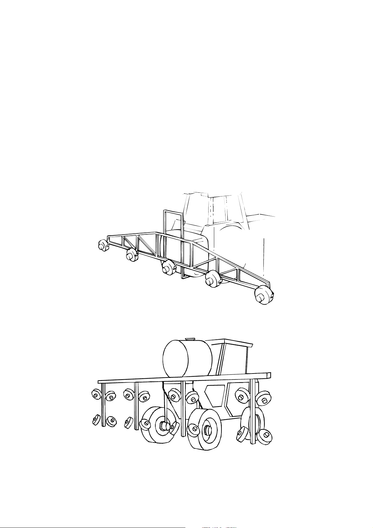
Figure 2. Typical sprayhead configuration for ground crops
Figure 3. Typical sprayhead configuration for grape harvester mounting (4 rows)
5
Page 7
DRAFT
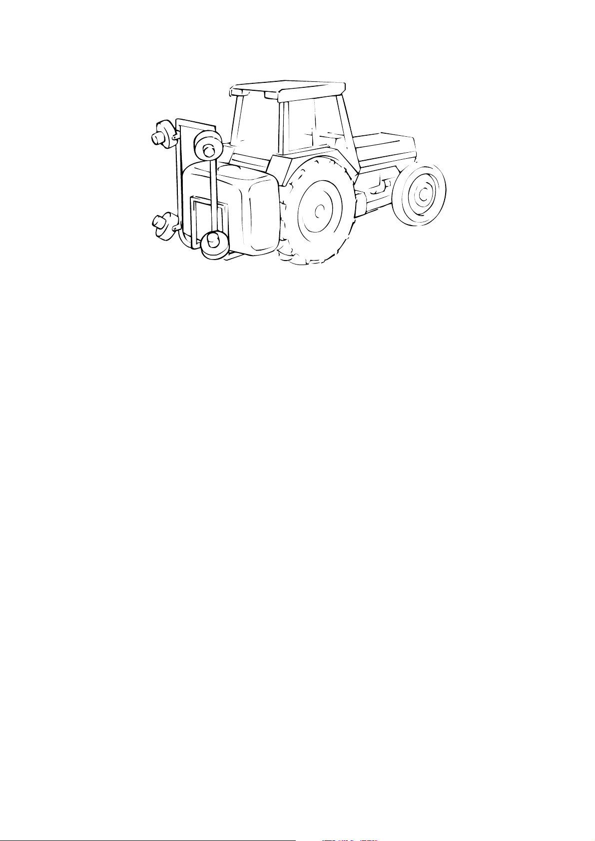
Figure 4. Typical sprayhead configuration for tree, bush and vine crops
4.1.1 Distance from Crop
Each sprayhead must be positioned sufficiently far from the crop to allow the airflow
from the fan to disperse the spray droplets over a wide band and to prevent local overapplication of foliage close to the atomiser. However, the distance should not be so great
that the airflow becomes dissipated or that the spray droplets could be prone to drift in a
wind. In general, a distance of 0.5 m (20 inches) to the outer face of the crop is preferred
in vines. This distance can be increased to 0.75 m (30 inches) if required.
4.1.2 Spacing of Sprayheads
Sprayheads must either be mounted sufficiently close together to produce an even swath
without ‘striping’ or should be positioned so as to spray specific rows of crops where the
rows are planted far apart and the space between does not require treatment.
For broadacre crops, closely planted vegetables etc, the sprayheads should be mounted on
a horizontal boom. Sprayheads should be not more than 1.2 m (4 feet) apart to ensure an
even swath.
For field crops planted in widely spread rows or beds and for low bush crops, a
horizontal boom can also be used. However, the sprayheads should be positioned either
above or between rows or bushes. Where the row spacing varies it may be necessary to
allow for adjustment of the position of sprayheads on the boom.
For trees, tall vines, soft fruit etc, the sprayheads will normally be mounted on a vertical
frame attached to the sprayer. One sprayhead will cover a vertical distance of 1 m (3 feet
6 inches). The number of sprayheads required will depend upon the height of the bush or
tree being sprayed and the density of the foliage. In general, dense foliage will attenuate
the airflow from a sprayhead more quickly and hence more units will be required to
ensure effective penetration and coverage.
6
Page 8

DRAFT
4.1.3 Angle of Sprayheads
Sprayheads should normally be angled so as to maximise the width of the band of spray
deposited and to allow the turbulent airstream to disturb foliage in order to achieve
maximum penetration and under-leaf coverage.
Sprayheads mounted on horizontal booms should face backwards with the axis of the
atomiser at an angle of 30 – 45 degrees to the vertical for fungicide and insecticide
application. However, they should face downwards at 0 – 10 degrees to the vertical for
herbicide or liquid fertilizer application.
Sprayheads used to spray sideways on tree or bush crops should face outwards from 0 –
45 degrees backwards to the direction of travel and should also be angled upwards or
downwards according to the foliage to be sprayed.
IMPORTANT: Sprayheads must never be positioned so that spray droplets can be
blown towards the driver or operator of the sprayer. Ensure that all spray is blown
clear of the sprayer structure to eliminate contamination and run-off.
4.2 Hydraulic System
Hydraulic power for Turbofan Sprayheads can be provided either from the tractor
hydraulic system or from an hydraulic pump driven by the power take-off (PTO) if there
is not sufficient capacity from the tractor.
The following notes are intended as a guide to the design of the hydraulic system and the
choice of components. When building a system it is vital that all components should
be selected so as to have a safe working pressure well in excess of the operating
pressure, taking into account the harsh environment of an agricultural operation.
4.2.1 Hydraulic Configuration
• It is recommended that Turbofan Sprayheads are normally connected in parallel
• Drain lines must be fitted to all motors.
It is possible to connect Turbofan Sprayheads in series but the numbers of motors in each
series chain should be limited to two. It is important to note that the pressure drop across
series pairs of motors is approximately 200 bar which is higher than most tractor
hydraulic systems can provide. Drain lines must also be fitted to all
motors connected in
series.
7
Page 9

DRAFT
4.2.2 Parallel Connection
The hydraulic motors of the Turbofan are normally connected in parallel.
To calculate the hydraulic flow required for a specific number of heads :-
• each head runs at 4000 rpm
• the oil flow required per motor is 4000 x 2ml/rev = 8 1/min
• add 10% for pump and other hydraulic losses = 8.8 l/min
eg For 6 heads hydraulic flow required = 8.8 x 6 = 52.8 l/min
Alternatively if you know the maximum hydraulic flow available from the tractor or PTO
pump, etc for the Turbofans then :
Maximum number of heads which can be installed = Maximum hydraulic flow available
8.8
eg If flow available = 72 l/min
then maximum number of heads (in parallel) = 72
= 8.18 = 8 heads
8.8
The pressure drop required per Turbofan Sprayhead is 100 bar (1500 psi) therefore the
maximum pressure required by the total hydraulic system for parallel running = 100 bar
(1500 psi).
4.2.3 Series Connection
The preferred method of running Turbofan Sprayheads is in parallel. However, if more
sprayheads are needed than can be connected in parallel, then series connection can be
used, subject to the following:
• A maximum of two motors must be used in each series chain.
• A hydraulic system with a relief valve setting of 200 bar (or above) is necessary for
series running (i.e. pressure drop of Turbofan unit x 2 = 100 bar x 2 = 200 bar).
• It should be noted that most tractor hydraulic systems operate below this figure and
are therefore unsuitable for running Turbofans in series (i.e. typical tractor hydraulic
systems operate in the range 140 – 180 bar).
It must also be noted that if the hydraulic system is running at 200 bar (or above) then all
of the components in the circuit must be capable of withstanding these pressures.
8
Page 10

DRAFT
To calculate the hydraulic flow required for a specific number of Turbofan Sprayheads
running in series pairs:
• Each head and each chain runs at 8.0 l/min
• Allow 10% for pump and other hydraulic losses. Therefore flow per chain (ie 2 x
Turbofan) = 8.8 l/min
• Therefore for 6 heads (3 chains of 2) the flow required = 8.8 x 6 = 26.4 l/min
2
Alternatively if you know the maximum hydraulic flow available (and the system
pressure is 200 bar or above) then :
Maximum number of heads which can be fitted = 2 x maximum hydraulic flow available
with 2 motors in series in each chain 8.8
e.g. If flow available = 72 l/min
then maximum number of heads in series (two per chain) = 2 x 72 = 16.4 = 16 heads
8.8
4.2.4 Hydraulic Oil Flow
If a Power Take Off (PTO) driven hydraulic pump is used, the pump should be chosen to
provide the calculated maximum oil flow plus losses and no more. If a larger pump were
to be used, any unused oil would have to be by-passed and would generate heat.
The specified output of the pump must match the calculated oil requirement (see sample
calculations in Sections 4.2.2 and 4.2.3)
When calculating pump output, ensure that the actual operating speed of the tractor is
taken into account. Many pumps are specified at 540 rpm nominal PTO speed. Most
tractors are driven at an engine speed corresponding to a lower PTO speed. For example,
if running at 500 rpm a pump rated at 100 l/min at 540 rpm will actually produce:
100 l/min x 500 rpm (actual)
= 92.6 l/min
540 rpm (nominal)
4.2.5 Hydraulic Pressure and Hose Size Selection
When designing a system and selecting a pump, the additional pressure drop across all
hoses and fittings must be taken into account. The working pressure of all components
must be adequate for worst-case conditions, including start-up pressure surges.
All hoses, pipes and fittings must be chosen to give an acceptably low pressure drop at
the maximum operating flow rate. The procedure to select the sizes of the pressure and
return lines is as follows:
a) On all pressure lines – calculate flow through each section, then use the design table
(Table 1) to select the appropriate diameters so that the total pressure drop along any
route from the pump to a sprayhead does not exceed 3.0 bar (45 psi).
9
Page 11

DRAFT
TABLE 1 – Pressure drop along hydraulic hoses
0
1
Table shows pressure drop in
pounds per square inch per 10
feet (3.04m) of hose without
fittings. Oil viscocity 20 centistrokes
-4 -4 -5 -6 -6 -8 -8 -10 -10 -12 -12 -16 -16 -20 -20 -24 -24
0.19 0.25 0.25 0.31 0.38 0.41 0.50 0.50 0.63 0.63 0.75 0.88 1.00 1.13 1.25 1.38 1.5
4.82 6.3 6.3 7.9 9.7 10.4 12.7 12.7 16.0 16.0 19.1 22.4 25.4 28.7 31.8 35.1 38.
L/M UG/M
HOSE SIZE
HOSE I/D (IN)
HOSE I/D (mm)
OIL FLOW
0.9 0..25 10 3.1 3.1
1.9 0.50 19 6.0 6.0 2.7
3.8 1.00 40 12.0 12.0 5..5 2.4
7.6 2.00 95 24.0 24.0 10.0. 4.8 3.5
11.3 3.00 185 46.0 46.0 17.0 7.0 5.0 2.2 2.2
15.1 4.00 78.0 78.0 29.0 12.0 8.0 3.0 3.0 1.2 1.2
18.9 5.00 120 120 44.0 10.0 12.0 4.5 4.5 1.6 1.6 0.7
30.2 8.00 95.0 39.0 26.0 10.0 10.0 3.6 3.6 1.4 0.6
37.8 10.00 59.0 40.0 15.0 15.0 5.7 5.7 2.0 1.0 0.6
45.4 12.00 80.0 52.0 20.0 20.0 7.2 7.2 2.6 1.5 0.8 0.4
56.7 15.00 75.0 30.0 30.0 10.0 10.0 4.2 2.2 1.2 0.6 0.4
68.0 18.00 107 40.0 40.0 15.0 15.0 6.3 3.0 1.5 0.7 0.6 0.4
75.6 20.00 49.0 49.0 19.0 19.0 8.0 3.4 2.0 1.1 0.7 0.5 0.3
94.5 25.00 72.0 72.0 26.0 26.0 11.0 5.5 3.0 1.6 1.0 0.6 0.4
113 30.00 34.0 34.0 14.0 7.0 3.6 2.2 1.3 0.8 0.5
132 35.00 47.0 47.0 19.0 9.5 5.0 2.8 1.7 1.1 0.7
151 40.00 25.0 12.0 6.5 3.4 2.2 1.4 0.9
189 50.00 36.0 17.0 9.0 5.3 3.3 2.0 1.3
10
Page 12

DRAFT
O
b) On all return lines – assume that valves, fittings, etc can cause up to 10 psi (0.7 bar)
back-pressure. Refer to Table 1 to select hose sizes which give a maximum additional pressure drop of 10 psi (0.7 bar) on any route from a sprayhead to the reservoir.
c) Motor drain lines MUST be returned back to the oil reservoir in an open unrestricted
flow and MUST NOT have more than 75 psi (3.0 bar) total back pressure as the hydraulic motor shaft seal may rupture. To check the back pressure place a low pressure gauge in the case drain line on the motor furthest from the oil reservoir and with
the unit running read the pressure. If the pressure is above 75 psi (3.0 bar) the motor
drain line must be replaced with a larger diameter line.
4.2.6 Hoses, Fittings and Motor Connections
All pressure lines must be flexible hydraulic hose or steel hydraulic tube of the appropriate pressure rating.
Any type of hose fitting can be used, but the standard 37 degree JIC flare type is recommended wherever possible. Large radius hose elbows should be used to minimise pressure drops.
High pressure hose should preferably be terminated with swage type fittings. However,
if re-usable types are selected, they should never be re-used more than three times.
IMPORTANT: Never use galvanised water pipe or fittings in any part of an hydraulic
system.
Micron recommend connecting the hydraulic motors of sprayheads in parallel. If connected in series a maximum of two motors in each series chain should be used.
The supply and return connections MUST NOT be reversed as the fan will run in the opposite direction with little or no airflow.
T
U
O
L
I
O
N
I
L
I
M
O
T
O
R
L
D
I
N
R
E
A
I
N
Figure 5. Hydraulic motor connections
DRAIN LINES MUST BE FITTED. TOTAL BACK PRESSURE OF COMBINED
DRAIN LINES MUST NEVER EXCEED 3 BAR OR MOTOR SEAL FAILURE
WILL RESULT.
11
Page 13

DRAFT
4.2.7 System Protection
Any self-contained hydraulic system MUST be protected by a relief valve from the pressure side of the pump to the reservoir. This should be of the self re-setting type.
• For parallel running this must be set to 120 bar (1800 PSI) minimum.
• For series chains (two motors maximum) this must be set to 220 bar (3300 PSI) mini-
mum.
It is especially important to check that all other components and hoses are suitably specified for safe working at these higher pressures.
4.2.8 Pressure Surge Prevention
When stopping the sprayheads, it is important that neither the pressure nor return lines
are suddenly closed. The inertia of the atomisers can continue to drive the motors as
pumps and produce a high back-pressure in the system. The simplest method of stopping
the sprayheads is to by-pass all oil from the pump to the reservoir, leaving the ends of the
chains of sprayheads open. If this is not practical, a non-return valve may be fitted to allow oil to re-circulate as the motors decelerate. This option is shown in Figs 6 and 7.
4.2.9 Speed Regulation
The speed of all sprayheads may be regulated by means of either a pressure compensated
flow control valve or a by-pass valve between the pressure line from the pump and the
reservoir. Possible options are shown in Figs 6 and 7. The valve must be of an adequate
size to handle 70% of the maximum pump output without excessive back-pressure or
overheating.
4.2.10 Hydraulic Oil
Only specially formulated hydraulic oils should be used with Turbofan Sprayheads. Engine lubricating oils must never be used. Shell Tellus 32 or equivalent hydraulic oil is
recommended for most conditions but Shell Tellus 37 or equivalent should be used in
tropical climates.
4.2.11 Oil Reservoir
The oil reservoir of a self-contained system must contain sufficient hydraulic oil to prevent overheating. As a rough rule, allow two litres of oil for every one litre per minute
displacement of the pump. Under tropical conditions it may be necessary to increase this
by 50%.
The return line to the reservoir must be taken to a point below the oil level to prevent
foaming. The inlet and outlet lines to the reservoir must be as far apart as possible and
not directly in line with each other. A baffle should be placed between the inlet and outlet sides of the reservoir. The reservoir should have an air space above the oil of at least
30% of the total oil volume, or 15 cm (6 inches), whichever is greater.
4.2.12 Cooling
Overheating of the system should not be a problem if the provisions of 4.2.11 above are
followed. However, if additional cooling is required, it may be necessary to return oil to
the reservoir via a heat exchanger. Ensure that this does not cause a significant backpressure. The use of metal (as opposed to flexible) hydraulic lines wherever possible in
the system will also help to cool the oil.
12
Page 14

PRESSURE GAUGE
ON/OFFVALVE
FLOW
DRAFT
CONTROL
VALVE
CHECK
PRESSURE SIDE FILTER
FILLER/BREATHER
PUMP
SUCTION
VALVE
RELIEF
STRAINER
IN PA RALLEL
OIL
RESERVOIR
SPRAY HEADS CONNECTED
RETURN FILTER
Figure 6. Typical self-contained hydraulic system
13
Page 15

PRESSURE LINE FR OM TR ACTOR
PRESSURE SIDE
RETURN
LINE
FIL TER
DRAFT
FIL TER
PRESSURE GA UGE
FLOW
CONTROL
CHECK
VALVE
OPEN CENTRE SYSTEM
PRESSURE LINE FROM TR ACTOR
RETURN
LINE
FIL T ER
Note: Return line may have
to be taken to oil filler
point of tractor
(see tractor manual
for details)
PRESSURE SIDE
FIL TER
PRESSURE GAUG E
NEEDLE
VALVE
CHECK
VALVE
CLOSED CENTRE SYSTEM
Figure 7. Typical systems connected to tractor hydraulics
14
Page 16

DRAFT
4.2.13 Filter
All hydraulic systems MUST be filtered. For sprayers using the tractor’s hydraulic system, a return line filter with a 25 micron replaceable cartridge and a full-flow by-pass relief valve should be fitted in the return line to the tractor.
A pressure side filter MUST also be fitted in order to protect the gear motors and shaft
seals. A 10 micron filter should be used located between the tractor remote hydraulic
coupling (supply) and the first component in the sprayhead hydraulic circuit.
Self-contained systems should preferably be fitted with a 125 micron suction strainer between the oil reservoir and the hydraulic pump. A 25 micron replaceable cartridge filter
with a full-flow by-pass relief valve must always be fitted in the return to the reservoir.
Ensure that the filters are of adequate size to maintain oil flow even when partially
blocked. The return filter should be fitted with a pressure gauge to monitor the condition
of the filter by checking the back-pressure.
A pressure side filter should also be fitted to self-contained systems. See Fig 6 .
4.3 Spray Liquid
The flow of spray liquid to each Turbofan Sprayhead must be regulated to give the
correct total output from the sprayer and consequently the required application rate on the
crop.
Chemical flow can be regulated by either a fixed or a variable restrictor unit in the
feedpipe to each sprayhead.
Fixed restrictors or variable restrictors are available from Micron Sprayers as optional
extras.
The MICRON fixed restrictor uses an orifice plate fitted in a housing which can be
installed into the inlet connection of the sprayhead (Page 25, Item No. 29 , Micron Part
No. 6197).
See Section 7 (’CALIBRATION AND ADJUSTMENT’) for full details of the fixed
restrictor calibration procedure.
Unlike hydraulic nozzles, Micron Turbofan Sprayheads do not require a high pressure to
operate. Droplet size is unaffected by system pressure. The pressure should, therefore,
be selected to give the correct liquid flow through the restrictor (see Calibration section).
If an existing sprayer is to be converted, the original spray pump can often be retained. If
this pump is a high pressure type or if it has excess capacity, it may be necessary to fit an
adjustable pressure regulator in the feed to the sprayheads. If a pressure regulator is
already fitted but cannot be adjusted to a sufficiently low pressure, it will be necessary to
fit a second low pressure regulator to the output of the main regulator. This allows the
first regulator to by-pass the majority of the surplus flow to the tank and provide a
stabilised input to the second regulator.
15
Page 17

DRAFT
If a new sprayer is being designed or an original pump is to be replaced, it is suggested
that a diaphragm or centrifugal type is chosen. This should be able to provide a pressure
of about 1 – 3 bar (15 – 45 psi) and should be capable of delivering the maximum flow
rate of the sprayer plus the flow required for tank agitation (if a mechanical agitator is not
used). An output of 60 l/min is satisfactory for most low volume sprayers without
mechanical agitation.
A chemical on/off valve must be fitted in the main feed to the sprayheads. This may be
mechanically or solenoid operated. A multi-position valve can be used to select different
groups of sprayheads if required.
A filter must be incorporated in the chemical supply to the sprayheads. This should have
an 0.5 mm (50 mesh/inch) or finer mesh filter. The filter may be installed either in the
suction or pressure line of the pump but the filter must always be before the flow
restrictors and should preferably be before the pressure regulator. Fig 8 shows the
recommended chemical feed configuration for a typical sprayer.
CHEMICAL
TANK
SUCTION STRAIN ER
RETURN LINE TO AGITA T OR
SPRAY HEADS
PRESSURE
GAUGE
CHEMICAL PUMP
ON/OFF AND
PRESSURE
CONTROL
VALVE
FLOW
RESTRICTORS
Figure 8. Typical configuration of chemical feed to heads
16
Page 18

DRAFT
4.4 Testing
Any new sprayer must be tested to ensure the following:
1. That the sprayheads all rotate at the correct speed.
2. That the chemical flow from each sprayhead is equal and that the flow can be
adjusted over the full range required.
3. That the sprayheads are correctly positioned to give the required coverage without
any tendency to ‘striping’. No spray droplets should be blown towards the operator
or onto the structure of the sprayer.
Full details of the procedures to achieve the above are given in the Section 5,
(‘OPERATION’) and Section 7 (‘CALIBRATION’) sections of this handbook.
5.0 OPERATION
As with all sprayers, optimum results will only be obtained from a machine fitted with
Turbofan Sprayheads if it is correctly calibrated, operated and maintained.
It is important that every operator who uses Micron sprayheads is completely familiar
with their calibration and use. The following sections emphasise points of particular
importance.
5.1 Daily inspection
All parts of the sprayer should be checked at least once a day. A complete check list for
the sprayheads is included in the Maintenance section of this Handbook. However,
particular attention must be paid to the condition of the atomiser discs, chemical
feedpipes and restrictors and all hydraulic hoses and fittings. All atomisers must run
smoothly without vibration.
5.2 Calibration Procedure
Before use, the sprayer must be calibrated for application rate. Full details are given in
the Section 7 (‘CALIBRATION’). It is important to note that the graphs and tables are
based on performance with water and are intended only as a guide. Actual performance
will vary according to the type and formulation of chemical being used. It is therefore
vital that the calibration of the system is checked whenever a new chemical is used.
5.3 Position of Sprayheads
The position and angle of sprayheads must be checked and adjusted as necessary before
use. When sprayheads are mounted on a boom, the boom height must be adjusted to suit
the crop being sprayed. See Section 4.1 (‘Mounting of Sprayheads’) for details of
recommended positions and angles of sprayheads.
When a sprayer is used for the first time on a new crop, the coverage of spray droplets on
the foliage should be checked to ensure that the sprayheads are correctly positioned.
The coverage can sometimes be assessed visually if the colour of the active material
leaves a clearly defined droplet (as with some fungicides). However, it is preferable to
place water sensitive papers in the foliage and to check the coverage by the droplet
density on the papers. Alternatively, a fluorescent dye can be added to the spray mixture
17
Page 19

DRAFT
and the coverage assessed viewing the droplets with an ultra-violet lamp in the dark.
5.4 Sequence of Operation
It is important that all sprayheads are rotating at their correct speed before the chemical
supply is turned on. Similarly, the chemical supply must be shut off before the
sprayheads are stopped. This ensures that a stream of chemical does not run out of the
atomisers and that the correct size of droplet is always produced.
When starting the rotation of sprayheads, the speed of the PTO or other hydraulic pump
drive should be reduced to a minimum and then increased to the normal level once the
units are running.
It is not normally necessary to stop the sprayheads every time the chemical flow is turned
off. However, the sprayheads must always be stopped before folding spray booms or if
there is the risk of accidental contact with foliage when turning at the end of a row.
5.5 After Use
The entire sprayer must be emptied and flushed out with clean water or a suitable solvent
after use. This eliminates the possibility of dried chemical residues blocking valves,
restrictors or atomiser discs. This precaution is particularly important when using
wetable powders as these will tend to sediment in the tank and pipework, causing serious
blockages when the sprayer is next used.
The atomisers should be rotating during the flushing process to distribute the chemical
and flushing liquid into the crop as spray droplets. This also ensures the most efficient
cleaning of the atomiser discs.
6.0 HEALTH AND SAFETY
Any sprayer using Turbofan Sprayheads must be used by a qualified operator in
accordance with the recommendations and statutory requirements for the use of sprayers
and the product being sprayed.
These requirements will be set out in the applicable local legislation and in the label of
the product being used.
In the United Kingdom, the precautions and regulations concerning the use of pesticides
and sprayers are defined in the Code of Practice for the Use of Pesticides on Farms and
Holdings (published by HMSO for the Ministry of Agriculture, Fisheries and Food and
the Health and Safety Commission).
The use of pesticides and sprayers are subject to legislation or codes of practice in most
other countries. It is the responsibility of the user to ensure that these are read,
understood and complied with.
18
Page 20

DRAFT
The following recommendations are for guidance only and do not exclude any statutory
requirements:
1. Always wear adequate protective clothing, eye protection and respiratory protection
when mixing, transferring or spraying pesticides. The minimum level of protection
will be stated on the chemical label or in the Code of Practices in most countries.
2. Protective clothing, respirators etc must be removed as soon as exposure to pesticides
has ceased. All items must be washed or disposed of safely according to the
manufacturers’ recommendations.
3. Ensure that the sprayer is correctly calibrated for the chemical, application technique
and crop or pest being sprayed.
4. Take note of the speed and direction of the wind. Ensure that spray droplets do not
drift on adjacent crops, another person’s land or an inhabited area. Do not drive the
sprayer upwind so that spray could be blown back towards the operator.
5. Never walk into a sprayed area until it is safe to do so according to the chemical
manufacturer’s recommendations.
6. All traces of chemical must be washed from the operator’s skin immediately after
spraying and before eating, drinking or smoking.
7. Remove all traces of chemical from the tank, pipework and sprayheads as well as
from external surfaces of the sprayer.
8. All residues of chemical from the sprayer, pesticide containers or mixing vessels, etc
must be disposed of safely by an approved means. Do not contaminate an off-target
area or allow pesticides to reach streams, wells or groundwater.
9. Dispose of empty chemical containers safely by an approved means. Do not keep
containers for re-use for other purposes.
7.0 CALIBRATION AND ADJUSTMENT
As with any sprayer, a machine fitted with Turbofan Sprayheads must be calibrated
before use.
The following sections describe the calibration of a typical sprayer using Turbofan
Sprayheads. The procedure may differ slightly for some specialised sprayers.
7.1 Application Rate
The output rate of chemical from the sprayer will be determined by the required
application rate (in litres/hectare) and the area sprayed per minute (in hectares/minute).
The flow of chemical from each sprayhead is usually controlled by an interchangeable
fixed restrictor orifice in the feed to the atomiser and by the spray chemical pressure.
Spray chemical pressure is controlled by the pressure regulator or by-pass valve in the
feed from the chemical pump.
19
Page 21

DRAFT
The following steps describe the calibration procedure in detail:
1. Establish the average forward speed of the sprayer. The most accurate means of
assessing the speed is to drive the sprayer in the actual crop. The speed can than be
calculated from the time to cover a measured distance.
2. Establish the width of the swath of spray on the target. In row and broadacre crops
this will be proportional to the boom width. In orchard, vineyard and soft fruit
spraying this can be determined by the row spacing and the number of rows sprayed
at a time.
3. Calculate the area treated by the sprayer per minute. As an example, Fig 9 shows the
sprayer being operated over a field crop.
If the sprayer is being driven at S km/hr this corresponds to 1000 x S metres/hour:
Distance travelled = 1000 x S metres/minute
60
If the width of the swath is W metres, then the area treated per minute is:
Area treated = 1000 x S x W metres 2 /minute
60
DISTANCE TRAVELLED
IN ONE MINUTE
SWATH WIDTH
W METRES
Figure 9. Coverage of sprayer
SPEED S KM/HR
20
Page 22

DRAFT
This is converted to hectares by dividing by 10,000:
Area treated = 1000 x S x W = S x W ha/minute
60 x 10,000 600
This gives the standard formula for calculating the coverage of a sprayer:
Area/min = swath width (m) x speed (km/hr) ha/min
600
Example:
Speed : 8km/hour
Swath width: 12 m
Therefore:
Area treated = S x W = 8 x 12 = 0.16 ha/min
600 600
Table 2 shows the coverage of the sprayer for various swath widths and spraying
speeds.
Table 2 – Coverage of sprayer in ha/min
SWATH WIDTH (metres)
SPEED
km/hr
4 6 8 10 15 20 25 30
4 0.03 0.04 0.05 0.07 0.10 0.13 0.17 0.20
6 0.04 0.06 0.08 0.10 0.15 0.20 0.25 0.30
8 0.05 0.08 0.11 0.13 0.20 0.27 0.33 0.40
10 0.07 0.10 0.13 0.17 0.25 0.33 0.42 0.50
12 0.08 0.12 0.16 0.20 0.30 0.40 0.50 0.60
14 0.09 0.14 0.19 0.23 0.35 0.47 0.58 0.70
4. Calculate the required output from the sprayer in litres/minute to give the correct
application rate for the chemical being used.
The output rate of chemical is given by the area sprayed (in hectares) per minute
multiplied by the required application rate in litres per hectare.
Example:
Coverage: 0.16 ha/min
Application rate: 100 l/ha
Output = 0.16 x 100 = 16 l/min
21
Page 23

DRAFT
5. Calculate the output of each sprayhead by dividing the total output of the sprayer by
the number of sprayheads.
Example:
Output: 16 l/min from sprayer
No of sprayheads: 8
Output/sprayhead = 16/8 = 2 l/min
6. Sel ect the correct fixed restrictor orifice to give the required flow rate per sprayhead
at the normal working pressure of the sprayer (typically about 2 bar or 30 psi). Table
3 gives the typical flow rates for fixed restrictor orifices. These figures are based on
measurements with water. Actual flow rates may differ according to the viscosity of
the chemical being used.
Table 3. Approximate flow rates for fixed restrictor orifices
RESTRICTOR No. FLOW RATE (litres/minute)
10 0.30 0.42 0.51
48 0.62 0.87 1.07
55 0.81 1.14 1.40
86 2.05 2.90 3.55
1 Bar (15 psi) 2 Bar (30 psi) 3 Bar (45 psi)
7. Fit the appropriate orifice in the fixed restrictor of each sprayhead.
8. Place a container under each sprayhead.
9. Ensure that the chemical on/off valve is closed.
10. Fill the tank of the sprayer with at least 50 litres of the chemical to be used or a liquid
of similar properties.
11. Start the chemical pump of the sprayer but do not run the hydraulic system.
12. Open the chemical valve until all air is purged from the hoses and sprayheads.
Return the chemical collected in the containers to the tank of the sprayer.
13. Place the containers back under the sprayheads and open the chemical on/off valve
again and collect chemical for a measured time of one or two minutes. Use a
measuring cylinder or calibrated container to measure the output and calculate the
flow rate in litres per minute per sprayhead.
14. Check that the flow from each sprayhead is the same and compare the total measured
output rate from all the sprayheads with the calculated rate from step (4).
15. If the actual output is slightly too high or too low, it may be possible to adjust it by
varying the spray chemical pressure.
16. If this adjustment is insufficient, the restrictor orifice for each sprayhead must be
changed to a smaller size to reduce the flow or a larger size to increase the flow.
17. The flow must always be re-checked after making any adjustments to the restrictors
or chemical pressure.
22
Page 24

DRAFT
8.0 MAINTENANCE
The Turbofan Sprayhead is manufactured from high quality materials which have been
selected for maximum strength, reliability and resistance to agricultural products. In
order to ensure a long and trouble-free working life, it is important that each sprayhead
should be periodically checked, cleaned and lubricated.
8.1 Routine Maintenance
Before each spray operation:
1. Check the general condition of the system, including hydraulic and chemical
hoses and fittings; repair any leaks.
2. Check condition of the bearing and hydraulic motor of each sprayhead by rotating
the atomiser by hand. Any roughness, stiffness or sideways movement indicates
that the unit requires maintenance.
3. Check the condition of the atomiser and fan blades. These should not be
damaged and must be free of any chemical contamination. Clean if necessary and
replace any damaged parts.
4. Check that each atomiser is correctly positioned and that its chemical flow
restrictor is correctly adjusted for the work being undertaken.
5. Check that the hydraulic system is adjusted to give the correct rotational speed for
all sprayheads.
Each day after spraying:
1. Empty any remaining chemical from the spray system.
2. Flush the entire system through with clean water or a suitable solvent. This
procedure is particularly important if chemicals containing solids in suspension
have been used as powder can settle out in pipework and cause blockage.
3. It is recommended that the outside surfaces of all sprayheads and booms are
washed down with a pressure washer or similar in order to prevent build up of
spray chemicals.
4. Ensure that all atomiser discs are free of contamination. Any build-up of dried
chemical degrades the droplet spectrum from an atomiser and may cause
vibration that can severely damage the unit.
8.2 Dismantling of Sprayhead
Should a sprayhead require maintenance, it must be dismantled and serviced as described
below. Numbers in brackets between 1 – 42 refer to parts of the sprayhead as shown in
the parts diagram on page 25.
IMPORTANT: Any defective parts must be replaced with genuine Micron spares.
Use of substitute parts or attempts at local repairs will void all warranties.
23
Page 25

DRAFT
1. Disconnect all hoses and remove sprayhead from the sprayer. Plug all free ends of
hydraulic hoses on the sprayer and all ports on the hydraulic motor.
2. Remove atomiser (1) by unscrewing screw (7).
3. Remove frontplate (10) complete with distributor (15) by unscrewing twelve
screws, nuts and washers (2,8,4) and four screws, nuts and washers (6,8,4).
4. Separate feed tube (34) from straight connection (27) fitted in the distributor by
pushing down on the top of the straight connector and pulling the feed tube out of
it.
5. Lift the front plate complete with distributor free of the main body and put to one
side.
6. Remove front shaft (14) and fan (21) from the main unit by undoing four capscrews
and washers (39,3). These two parts should be only a sliding fit on the hub (12)
and can be removed easily. (If the front shaft proves difficult to remove then a very
long M6 setscrew (or piece of M6 threaded bar) can be used as a puller by screwing
into the end of the front shaft and reacting against the end of the screw (33) inside
the hub).
7. Remove two off drive pins (40) and two pairs of lock washers (41).
8. Next remove the hub (12) from the bearing by unscrewing the four grubscrews (13)
and pulling the hub off by hand, or with the aid of a universal bearing puller.
9. Remove the hydraulic motor (22) complete with bearing (23) and shaft extension
(42) by undoing four screws, nuts and washers (6,8,4).
10. The bearing (10) can be removed from the motor by the use of a brass or
aluminium drift or a universal bearing puller. The bearing should only be removed
if it requires replacement.
11. The shaft extension (42) can be removed from the motor by removing the capscrew
(33), lock washer pair (37) and plain washer (38). The shaft extension can be
removed using either a suitable brass or aluminium drift or a small universal
bearing puller. Take care to retain the key in the motor shaft for future use. The
shaft extension should only be removed if it is either to be replaced or if
maintainence is necessary on the hydraulic motor involving the removal of the
hydraulic motor main shaft.
12. The motor support bracket (31) and rear guard (36) can now be removed if
necessary by undoing all remaining M6 screws and nuts (8,6,4,2).
24
Page 26

DRAFT
TURBOFAN (BASIC) PARTS LIST (TBF/200)
PART NO. DESCRIPTION QTY
4915 SCREW, M5 X 16, S/S 4
5245 NUT, M4 NYLOC 2
5472 SCREW, M6 X 16, SET, HEX, S/S 24
5722 WASHER, M6, FLAT, S/S 36
5887 WASHER, M6 X 25 OD, PLAIN, S/S 1
5971 SCREW, M6 X 25, SET, HEX, S/S 12
5983 SCREW, M6 X 20, SET, HEX, S/S 1
5984 NUT, M6, NYLOC, S/S 36
6058 FAN COWL 1
6061 SADDLE 2
6066 FAN, 4-BLADE 1
6067 MOTOR, HYDRAULIC, C/W KEY 1
6068 BEARING NO.6006LLUA/2A 1
6077 WASHER, M16, NORDLOCK (PAIR) 2
6078 SCREW, M16 X 40, SET, HEX, S/S 2
6079 WASHER, 5M X 15OD X 1.6, S/S 1
6138 KEY FOR HYDRAULIC MOTOR 1
6182 WASHER, M6, SHAKEPROOF 5
6184 CARRIER, MOTOR 1
6185 SPACER 4
6186 SCREW, M5 X 16, CAP HEAD, S/S 1
6187 WASHER, 5M NORDLOCK (PAIR) 5
6194 GUARD, REAR 1
6206 LABEL, DRAINLINE 1
6207 LABEL, ROTATION 2
6247 SHAFT, FAN/ATOMISER 1
6248 RING, LOCKING 1
6249 SCREW, M6 X 25, SOCKET 4
6256 SCREW, M4 X 25, PANHEAD 2
6266 DISTRIBUTOR BLOCK 1
6278 DRIVE CROSS 1
6283 FRONT PLATE (2 HOLE FEED) 1
6743 FEED TUBE 8MM OD BRASS 1
6746 ADAPTER MALE STUD 8MM X 1/8” BSPT (13480—8-18 TECH HOSE) 1
6793 ADAPTER 1/4” BSP F/F 1
6794 ADAPER MALE STUD 8MM x 1/4” BSP 1
AJ6379 BODY 1/4” LFM BRASS 1
AJ6380 CAP LF BRASS 1
AJ6381 HOSE BARB 3/8” BRASS 1
MICRON ATOMISER PARTS (TBF/003)
6261A ATOMISER STACK ASSEMBLY 1
6277 WASHER, M8, FIBRE 1
6262 BOLT, BANJO (MICRON) 1
6263 FEED BODY (MICRON) 1
6267 SPACER (MICRON) 1
MICRONAIR ATOMISER PARTS (TBF/004)
6277 SEAL, BONDED 1
6279 ATOMISER GAUZE 1
6280 ATOMISER HUB 1
6281 BOLT, BANJO 1
6282 FEED BODY 1
6258 SCREW, 8-32 UNC X 100 DEGREE 3
25
Page 27

TURBOFAN PARTS DIAGRAM
AJ 6381
AJ 6379
AJ 6380
6793
6184
6794
DRAFT
5971
5722
5984
5971
6185
5722
6207
5984
5984
5722
6087
6078
6067
6249
6077
6138
6248
6194
6061
5984
6068
5722
6411
5971
6278
6079
6058
6187
5245
6186
6746
6266
6256
6743
6283
6066
6061
5984
5722
5472
5971
5722
5984
6277
6282
6281
MICRONAIR A T OMISER
6279
6280
6238
MI CRON A TOMISER
6277
6262
6263
26
6187
6261A
4915
6247
6182
5472
5887
6182
5983
Page 28

APPENDIX A
TURBOFAN HYDRAULIC MOTOR DOUBLE SEAL ARRANGEMENT
WITH "TELL-TALE" BOTTLE
A
B
E
D
Since February 2003 the hydraulic motor driving the Turbofan head has been fitted with a
double oil seal arrangement. Between the two seals there is a port connected to outside via
the flange of the motor. This port is connected to a small "tell-tale" bottle of transparent
plastic. A failure of the first seal will result in oil being passed into the bottle.
If oil is observed in either the bottle or the pipe leading to it, the machine must be stopped
and the seals (both) replaced.
This arrangement is shown in the above illustration.
KEY:
A = Hydraulic Motor Part No. 6358 B = Pipe Part No. 4993/8
C = Bottle Part No. 6574 D = Clip Part No. 6573
E = Nozzle Part No. 6575
C
NOTE: THE PURPOSE OF THE BOTTLE IS TO SHOW LEAKING OIL. DO
NOT PUT OIL IN THE BOTTLE.
 Loading...