

Page 1

User’s Guide
TransPort LT
Copyright Notice
User’s Guide
Copyright Notice
The information in this document is subject to change without prior notice in order
to improve reliability, design, and function and does not represent a commitment
on the part of the manu facturer. In no event will the ma nufacturer be liable for
direct, indirect, special, incidental, or consequential damages arising out of the
use or inability to use the product or documentation, even if advised of the
possibility of such damages. Except as stated in the applicable Micron Electronics
limited warranty, Micron, by this manual, makes no other express warranties and
all other warranties, including, without limitation,
MERCHANTABILITY AND THE IMPLIED WARRANTY OF FITNESS FOR A
PARTICULAR PURPOSE ARE HEREBY DISCLAIMED
This document contains proprietary information that is protected by copyright. All
rights are reserved. No part of this document may be photocopied, reproduced, or
translated to another language without the prior written consent of:
Micron Electronics, Inc.
900 E. Karcher Road
Nampa, Idaho 83687
Phoenix is a trademark of Phoenix Technologies Ltd. CardSoft is a trademark of
SystemSoft Corporation. AutoCAD and Autoshade are trademarks of Autodesk,
Inc. IBM, OS/2, and VGA are trademarks of International Business Machines
Corp. Lotus, 1-2-3, and Symphony are trademarks of Lotus Development Corp.
Windows, Word, MS-DOS, and Microsoft are trademarks of Microsoft Corp. VESA
is a trademark of Video Electronics Standards Association.
THE IMPLIED WARRANTY OF
.
P/N MAS001602-00, TransPort LT,
BGJ, 01-20-2000
MS-DOS, Windows 3.1, 95/98/2000 and Windows NT are trademarks of Microsoft
Corp. Pentium II and MMX are trademarks of Intel Corporation. Other product
names mentioned herein are used for identification purposes only and may be
trademarks and/or registered trademarks of their respective companies. While
reasonable efforts have been made to ensure the accuracy of this manual, the
manufacturer and distributor assume no liability resulting from errors or omissions
in this manual, or from the use of the information contained herein.
Copyright 2000 Micron Electronics Inc. All Rights Reserved.
1
Page 2

This page intentionally lef t blank.
2
Page 3

Table of Contents
Table of Contents
User’s Guide............... ...... ....... ........................................... 1
Copyright Notice.................................................................... 1
Welcome ............................................... ...... ........................ 7
Purpose.................................................................................. 7
Reader.............................................................................. 7
Further Reading..................................................................... 7
Areas Covered....................................................................... 7
Manual Conventions.............................................................. 9
Manual Comments................................................................. 9
Getting Started................................................................. 11
Unpacking the TransPort LT............................................... 11
Personal Inventory.............................................................. 12
System Information ........................................................ 12
Heat, Cold, Humidity, and Glare ......................................... 13
Surge Suppressors ............................................................. 13
Work Location........................................... ...... ..... ...... .......... 13
Operating Environment............................................. .......... 15
Introducing Your TransPort LT....................................... 17
TransPort LT Features......................................................... 17
Using Your Computer for the First Time ........................... 19
Connecting the AC Adapter............................................ 19
Turning on the TransPort LT.......................................... 20
Understanding POST........................................................... 21
Adjusting the LCD Display.................................................. 22
Turning Off Your Computer ................................................ 22
APM Mode...................................................................... 22
Restarting Your Computer.................................................. 22
Tips for Using Your Computer ............................................ 23
Traveling with Your Computer............................................ 24
Handling Spills..................................................................... 25
Storing the Computer for Long Periods............................ 25
Using the Keyboard............................................................. 25
Using the Embedded Numeric Keypad.......................... 27
Using Special Function Keys ......................................... 27
Using the Touchpad ............................................................ 28
Reading the System Status Lights .................................... 29
Connecting Peripheral Devices......................................... 31
Using the Flex-Bay.............................................................. 33
To Remove a Device from the Flex-Bay........................ 34
To Install a Device in the Flex-Bay................................. 34
Using the SmartBay Utility............................................. 34
Using the Floppy Drive....................................................... 35
Using the CD-ROM Drive.................................................... 37
Using the Hard Drive........................................................... 39
Removing the Hard Drive............................................... 40
Installing a Hard Drive.................................................... 41
Using the Battery................................................................. 41
Charging the Battery...................................................... 41
Safely Using the Battery................................................. 42
Removing the Battery..................................................... 42
Installing the Battery....................................................... 43
Monitoring the Battery Charge....................................... 43
Using the Battery Gauge................................................ 44
Using PowerProfiler to Monitor the Battery.................... 44
Battery Warnings............................................................ 45
Using the Modem ................................................................ 46
Precautions Before Use................................................. 46
Description of 56K.......................................................... 47
Modem Specifications.................................. ..... ...... ..... .. 48
Installing the Modem Driver in Windows 95/98................ 49
Modem Commands................................................. ..... .. 49
Using AT commands...................................................... 50
Basic AT Commands..................................................... 51
Video Features and Configuration.................................. 53
Resolution and Color Depth............................................... 53
Configuring Display Features......................................... 54
Selecting a Monitor Type ............................................... 54
Changing Color Depth and Resolution........................... 55
Changing the Video Driver............................................. 56
Working with PC Cards....................................................... 58
Maintaining PC Cards.................................................... 59
Using PC Cards ............................................................. 59
3
Page 4

Table of Contents
Using Options................................................................... 63
AC Adapter........................................................................... 63
Auto Adapter........................................................................ 63
Battery Pack......................................................................... 64
Memory Modules.................................................................. 64
Before You Install Memory............................................. 64
Installing a Memory Module............................................ 65
CD-ROM Drive...................... ...... ....................................... ... 67
DVD-ROM Drive Module...................................................... 67
Secondary Battery............................................................... 67
Port Replicator....................................................... ..... ...... ... 68
Features of the Port Replicator....................................... 68
Installing a Port Replicator.............................................. 69
Removing a Port Replicator............................................ 70
Drivers and System Resources....................................... 71
Drivers .................................................................................. 71
IRQs ...................................................................................... 71
Service Pack 6A for Windows NT 4.0................................. 72
Installing the LAN Driver in Windows 98........................... 73
Using System Setup......................................................... 75
Starting System Setup......................................................... 75
Main Menu............................................................................ 77
Advanced Menu................................................................... 81
Security Menu...................................................................... 83
Power Menu........................................... ...... ..... ...... ..... ...... ... 84
Boot Menu ............................................................................ 87
Exit Menu.............................................................................. 88
Using System Security..................................................... 89
System Passwords.............................................................. 89
Creating a Password...................................................... 89
Deleting a Password....................................................... 90
Requiring a Boot Password............................................ 90
Locking the Hard Drive Boot Sector............................... 90
Locking the Floppy Drive................................................ 90
Locking the Keyboard..................................................... 91
Using Power Management Options ................................ 93
Maximum Power Saving Mode........................................... 93
Standby Mode...................................................................... 93
Suspend Mode..................................................................... 94
Suspend Mode Precautions........................................... 94
Using PowerProfiler............................................................ 95
Creating a Save-To-Disk Partition.................................. 97
Software Utilities.............................................................. 99
MRestore CD-ROM .............................................................. 99
MCRC (Micron Customer Resource Center)..................... 99
PartitionMagic...................................................................... 99
Drive Image 3.0.................................................................... 99
Drive Image Professional.................................................. 101
Drive Image System Requirements..................... ..... .... 101
Creating Image Files.................................................... 101
Advanced Options........................................................ 107
Disable SmartSector Copying...................................... 107
Verify Disk Writes......................................................... 107
ImageShield................................................................. 108
Split Image File Into Multiple Files................................ 108
Restoring Image Files.................................................. 108
Resize Options............................................................. 114
Advanced Options........................................................ 114
Check for File System Errors....................................... 115
Skip Bad Sector Check ............................................ .... 115
Verify Check Writes...................................................... 115
PartitionMagic.................................................................... 115
Partition Information..................................................... 116
Partition Map..................... ........................................... 116
Partition List.................................. ................................ 116
PartitionMagic Help...................................................... 117
ReadMe File................................................................. 117
Completing Tasks Manually......................................... 117
Selecting a Hard Disk................................................... 117
Selecting a Partition..................................................... 118
Applying Changes to Your System............................... 118
Changing PartitionMagic Preferences.......................... 119
Ignore OS/2 EA Errors on FAT..................................... 119
Skip Bad Sector Checks............................................... 120
Set as Read-Only for PartitionMagic............................ 120
Creating Partitions........................................................ 121
4
Page 5

Table of Contents
Creating Bootable Partitions......................................... 121
To Create a Partition.................................................... 122
Scenarios ..................................................................... 125
Deleting Partitions.................... ...... ..... ...... ................... 125
Changing Partition Labels ............................................ 126
Formatting Partitions.................................................... 127
Converting FAT to FAT32 ............................................ 128
Converting FAT to NTFS.............................................. 128
Drive Copy................................................. ..... .............. 130
Copying Entire Drives................................................... 130
PHDISK Utility.................................................................... 132
Help Screen.................................................................. 132
CREATE Option .................................. ...... ..... ...... ...... .. 132
Automatic Memory Size Calculation............................. 133
User-specified Memory Size......................................... 133
/Partition or /P............................................................... 133
/CREATE Option Syntax.............................................. 133
REFORMAT Option...................................................... 133
INFO Option................................................................. 133
PHDISK Sign-on Message........................................... 134
Unrecognized Option.................................................... 134
PHDISK/CREATE Failed to Execute............................ 134
Fatal Error .................................................................... 134
Save-To-Disk Partition Exits......................................... 134
First Two Sectors Bad.................................................. 134
Restoring your Computer ............................................. 137
Appendix A - Regulatory ............................................... 149
FCC Notice......................................................................... 149
Federal Communications Commission (FCC) Part 68
Statement 149
CTR21 Statement............................................................... 151
Canadian Radio Interference Regulations...................... 151
CLASS 1 LASER PRODUCT ............................................. 151
Power Cord Requirement................................................. 152
Appendix B - Important Safety Instruction .................. 155
Battery Disposal................................................................ 157
Appendix C - Abbreviations .......................................... 159
Appendix D - Glossary................................................... 161
To (re)install your Operating System:.............................. 137
Windows 98:............................. ...... ..... ......................... 137
Windows NT 4.0 Workstation:...................................... 138
To (re)install your original applications and drivers:..... 138
Troubleshooting............................................................. 139
Operating Problems............................ ..... ...... ................... 139
Infrared Problems................................ ..... ...... ..... .............. 140
Modem Problems............................................................... 141
Specifications................................................................. 143
System Specifications ...................................................... 143
Recording the Computer Hardware Configuration..... 145
5
Page 6

This page intentionally lef t blank.
6
Page 7

Welcome
Chapter 1 - Welcome
Purpose
Thank you for buying a micronpc.com computer. This User’s Guide is intended for
both first-time and experienced computer users. Please review the following
information to get the most out of this manual.
Purpose
Reader
Further Reading
Areas Covered
This manual contains information to instruct and guide you on everyting from
setup and maintenance to configuring the system and creating disk partitions. The
purpose of this manual is to help you enjoy all the features the TransPort LT offers
and information to help you operate and setup the computer for optimal
performance.
This manual is designed to assist all users—from beginner to advanced.
The first two chapters are intended for all users. The rest of the manual is targeted
toward the reader who has a basic understanding of how computers work and
how to use them.
If you are new to using computers, see the Glossary for explanations of general
computing terms that are used in this manual. The Glossary also provides
information about some of the differences between notebook computers and
desktop computers.
Along with this manual you should consult and read all the manuals and
documentation included with all software and hardware applications used with this
computer.
Your computer shipped from the factory with several software programs installed.
The software may include its own online or printed documentation. Refer to the
documentation or the Help options in the software for more information.
Getting Started:
general operating guidelines. This chapter contains important computer use and
computer care considerations to help you get started.
This section includes a description of the parts you received and
Introducing Your TransPort LT:
features of the TransPort LT along with basic operation.
Video Features and Configuration:
capabilities of your computer and information on working with PC cards.
This section provides a description of the
This section describes the display
7
Page 8

Welcome
Areas Covered
Using Options:
This section provides an overview to numerous options with
which you can increase the uses for your TransPort LT. If you have purchased
accessories, refer to this chapter for instruction, if not, you may want to find out
what kinds of options you have with your TransPort LT.
Drivers and System Resources:
This section gives you basic information about
drivers and system IRQs.
Using System Setup:
This section describes how to operate the System Setup
Utility that is provided in the computer’s ROM BIOS. No changes should be made
in Setup unless the result of the change is known and understood.
Using System Security:
This section describes the security options provided
with your computer.
Using Power Management Options:
This section provides information on how
to keep your TransPort LT supplied with power.
Creating a Save-To-Disk Partition:
This section describes your computer’s
save-to-disk partition and provides instructions for adding memory modules to
your computer.
Software Utilities:
This section explains the MRestore CD, which includes Drive
Image, Partition Magic and Drive Copy--three very powerful software tools--and
the PHDISK (save-to-disk) utilit y.
Restoring your Computer:
This section explains how to restore the Operating
System or drivers.
Troubleshooting:
This section provides a simple guide to common
troubleshooting techniques.
Specifications:
Recording the Computer Hardware Configuration:
This section lists the specifications of your TransPort LT.
Use this section to record
the System Setup program settings.
8
Page 9
Welcome
Manual Conventions
Manual Conventions
Special Text
AUTION
C
ARNING
W
N
OTE
The following conventions are used throughout this manual:
Notes: Important information and useful tips concerning the operation of your
:
computer.
Caution: Failure to follow directions could result in loss of data or damage
:
to equipment. Failure to heed these warnings could negate the user
warranty.
Warning: Failure to follow directions will result in loss of data or damage to
:
equipment, and/or could result in physical harm. Failure to heed these
warnings could negate the user warranty.
The text if formatted to set off unique information or instructions. Review the
following examples of special text used throughout this manual:
•
Screen (window) names, functions, or anything that appears on the screen
is formatted in bold: Click OK, the
•
Keyboard functions are indicated by brackets: Press [Enter], use the [Alt]
key. When keys should be held down symultaniously they are separated by
the + sign: Press [Ctrl+Alt+Delete].
•
Screen messages are indicated by quotes: the message “Enter your
username and password” will appear.
•
Anything that you need to type in should appear in italics: Enter the word
password
.
Standards
screen, the
Edit
menu.
Manual Comments
We want to make this guide as useful as possible and welcome your comments.
Please provide the page and the manual part number (MAS001602-00) when you
send comments to: [email protected].
9
Page 10

This page intentionally lef t blank.
10
Page 11

Getting Started
Chapter 2 - Getting Started
Congratulations on the purchase of your Micron Transport LT notebook computer.
Whether you are new to using a notebook computer or are an experienced user,
this user manual can help you get the most from your computer.
Unpacking the TransPort LT
Unpacking the TransPort
LT
OTE
N
The TransPort LT comes securely packaged in a sturdy shipping carton. Open the
box and carefully remove the contents. If anything is missing or damaged, please
contact Micron Electronics immediately. All systems should include the following
items:
•
The TransPort LT computer
•
An AC adapter
•
An AC power cord
•
User’s manual
•
A CD or DVD-ROM Drive
•
A 3.5-inch Floppy Drive
Items included may vary. Please check the packing slip included with your
:
TransPort LT for the exact items you should have received.
11
Page 12
Getting Started
Personal Inventory
Personal Inventory
System Information
This TransPort LT computer system is designed for years of productive and
pleasurable computing. Use this section to keep notes about details of your
purchase. Update this section when you add new options.
Please record your computer’s operating information. If you should require
technical support in the future, the following information will help the Micron
Support Technician locate the specifications for your system and aid in returning it
to normal operation.
Model and Serial Number Information
Purchase Date
Model Number
Serial Number
Order Number
Customer Number
Manual Number MAS001602-00
Micron Technical Support:
Technical Support File Library:
Address:
1-888-FIX-MYPC (1-888-349-6972)
http://support.micronpc.com/library/
Micron Electronics, Inc.
900 East Karcher Road
Nampa, Idaho 83687
12
Technical Support Internet Mail:
1. To send an email to Technical Support visit the Micron Electronics Website:
http://support.micronpc.com/contact/support/.
2. Click on the
Web site:
www.micronpc.com
Support Department
for your specific need.
Type of LCD screen display:
•
12.1" Color TFT XGA LCD
•
13.1” Color TFT XGA LCD
Page 13
Getting Started
Heat, Cold, Humidity, and Glare
OTE
N
Heat, Cold, Humidity, and
Glare
ARNING
W
CPU Type:
Hard Disk Capacity:
Memory Capacity:
If your system arrives in cold weather, do not apply power to the computer until it
:
has reached room temperature.
Find a spot for your computer that’s not too hot, too cold, too dark, or too bright.
Glare can make it hard to read the screen. Overheating can destroy computer
components, so allow plenty of room for air to circulate around the case. Do not
place your TransPort LT in direct sunlight.
Do not expose the notebook to cold (frost) or heat, do not leave the
:
notebook in a car, and do not drop it, spill fluids on it, or open the case. This
can destroy the notebook and void the warranty. The system’s Liquid
Crystal Display (LCD) video display may be damaged by exposure to
intense sunlight, which builds up excessive heat inside the display
enclosure. Only exposure to indirect or subdued sunlight is recommended.
__________________________________
___________________________
___________________________
Surge Suppressors
Work Location
Your computer has its own electrical filters, fuses, and protections, and even its
own built-in surge suppressor. However we strongly recommend using a highquality, external surge suppressor. An external surge suppressor looks like an
extension cord with several grounded outlets. It will help shield your computer
from lightning strikes, surges, shorts, and other electrical hazards.
Your TransPort LT generally will run well in conditions you are comfortable in. But
extremes of temperature and humidity can be challenging to your system’s parts.
There are, however, some things you can tolerate that the computer can’t —
things like static electricity, dust, water, steam, and oil.
13
Page 14

This page intentionally lef t blank.
14
Page 15

Getting Started
Operating Environment
Operating Environment
You can use your computer under a wide range of environmental conditions.
However, to ensure long use and continued high performance, consider the
following factors when setting up your computer:
•
Set the computer on a flat, stable surface. To prevent damage to the
computer’s hard disk drive avoid using the computer where it will be
exposed to strong vibration.
•
Place the computer away from electromagnetic or radio frequency
interference (for example, television/stereo sets, copying machines, and air
conditioners).
•
Avoid using or storing the computer where it will be exposed to extreme
temperatures. In particular, do not leave the computer in direct sunlight,
over a radiator, or near a heat source for a long period of time. High
temperature can damage the circuitry.
•
Avoid exposing the computer to high or low humidity. Extreme humidity can
contribute to disk drive failure.
•
If you are using the computer with the AC adapter, do not allow anything to
rest on the power cord. Do not place the computer where people can step
on or trip over the cord.
•
The openings on the computer are provided to protect the computer from
overheating. To ensure reliable operation, leave about 10 cm (4 inches)
around the computer for unobstructed air circulation. Avoid exposing the
computer to dust or smoke.
15
Page 16

This page intentionally lef t blank.
16
Page 17
Introducing Your TransPort LT
Chapter 3 - Introducing Your TransPort LT
Your computer is a lightweight portable computer that includes features to meet
your computing needs at home or on the road.
TransPort LT Features
TransPort LT Features
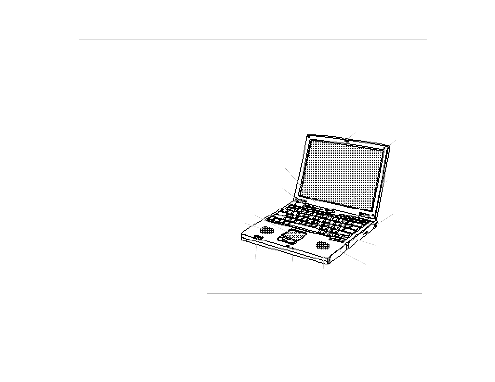
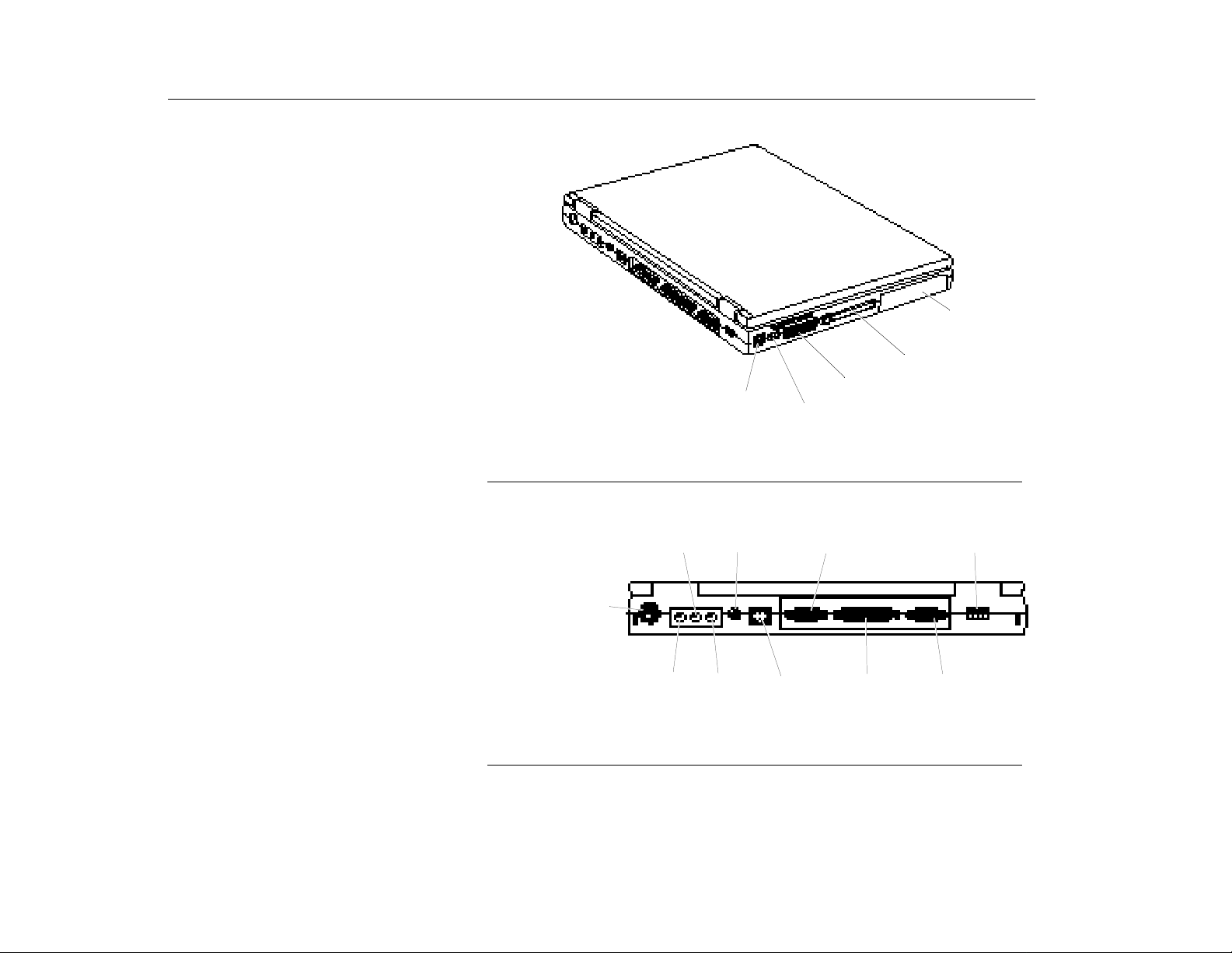
Figure 1, Figure 2, and Figure 3 illustrate the features of your computer.
Cover latch
Status lights
Power button
Kensington lock
CD-ROM drive
Touchpad &
Mouse Buttons
Speaker
Status lights
Volume control
Microphone
Speaker
Battery compartment
LCD
Figure 1. Front and Right view of Computer
17
Page 18
Introducing Your TransPort LT
TransPort LT Features
Hard drive
compartment
PC Card compartment
Modem jack
(Optional)
Figure 2. Bottom View of Computer
Line-in
PS/2™
mouse and
keyboard
port
Microphone
jack
Figure 3. Back View of Computer
Power
Connector
Headphone
jack
Infrared port
Serial port
LAN port
(Optional)
Fan vent
Parallel port
USB port
Video port
18
Page 19
Introducing Your TransPort LT
Using Your Computer for the First Time
Using Yo ur Com puter for
the First Time
Connecting the AC Adapter
This section gives you detailed information on using your computer for the first
time.
Your computer runs on power from the battery in the computer or from an
electrical outlet. The first time that you use your computer, fully charge the battery
by attaching the power cord to the computer and to an electrical outlet.
To attach the power cord:
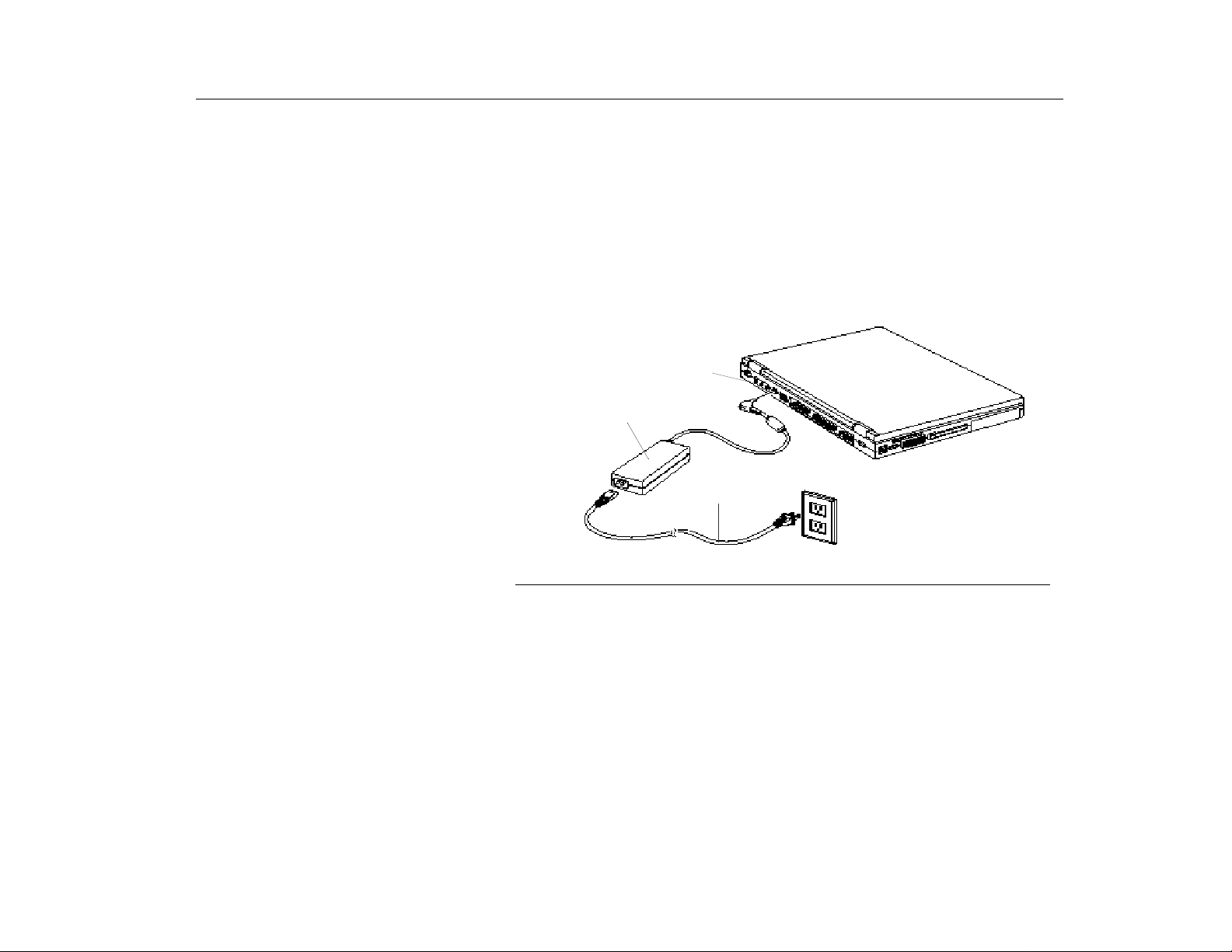
1. Plug the AC adapter into the power connector on the back side of the computer
(Figure 4).
2. Connect the power cord to the AC adapter and then to an electrical outlet.
Power connector
AC Adapter
Power cord
Figure 4. Connecting the AC Adapter
The battery starts charging as soon as you plug the power cord into an electrical
outlet. The battery charges faster if the computer is off.
If the battery is fully depleted and the computer is turned off, the battery charges
in about two and a half hours. If the computer is turned on, the battery charges in
about four hours. When the battery is charging, the battery charge light is amber.
When the battery is fully charged, the light turns green.
See ”Using the Battery” on page 41 for more information on using your computer’s
battery.
19
Page 20

Introducing Your TransPort LT
C
AUTION
Using Your Computer for the First Time
:
The best kind of AC power source to connect your TransPor t LT to is a UPS
(Uninterrupted Power Supply). If you do not have an UPS, use a power strip
with a built-in surge protector. Do not use inferior extension cords as this
may result in damage to your TransPort LT. The TransPort LT comes with
its own AC adapter. Do not use a different adapter to power the computer,
and do not use the AC adapter to power other electrical devices. Damage to
the computer that is caused by using a different power source will not be
covered under warranty.
Turning on the TransPort LT
To turn on the computer’s power for the first time:
1. Push the cover latches on the front of the cover to the right and hold.
2. Lift up the cover.
3. Press and then release the power button (Figure 5).
The power light is green when the computer’s power is on.
Cover latch
Power light
Figure 5. Turning On the Computer’s Power
Power button
20
Page 21
Introducing Your TransPort LT
C
AUTION
Understanding POST
:
Never turn off or reset your TransPort LT while the hard disk or floppy disk
is in use and the FDD and/or HDD status icon is lit; doing so can result in
loss or destruction of your data. Always wait at least five seconds after
turning off your TransPort LT before turning it back on. Turning the power
on and off in rapid succession can damage the TransPort LT’s electrical
circuitry.
Before you run your system for the first time on battery power, recharge the
battery fully to prepare the battery pack for maximum service. When
selecting a suitable working location, please consider the ventilation,
temperature, dust and dirt, plus electromagnetic and RF interference. The
selected location should provide a sturdy and reasonably level surface with
at least four inches of open space around the computer cabinet for proper
airflow. Your computer functions best at room temperature. Choose a
location free from extreme heat or cold.
Except for PC cards, never connect or disconnect any equipment or
components while the system power is on.
It is important not to operate the notebook on soft surfaces--such as a bed-as this will cover the ventilation holes of the notebook.
There is one fan on the left side of the notebook, which will t urn on when the
CPU temperature exceeds 60 degrees Celsius. The fan will turn off when the
CPU temperature is below 50 degrees Celsius.
W
Understanding POST
ARNING
:
If the temperature continues to rise above the CPU allowable limit--either
due to a defective fan, or the notebook being operated in an excessively hot
environment, or a soft surface that covers the ventilation holes--then the
notebook will shut down and all unsaved data will be lost.
When you turn on your computer, a procedure called POST (Power-On Self-Test)
automatically runs to test the computer components. Several messages appear
on the screen during POST.
Screen messages are built into the computer to report both normal and abnormal
system conditions. If an error message appears, take any action suggested in the
message. If the message identifies the error condition but does not suggest any
corrective action, write down the message and contact micronpc.com Technical
21
Page 22
Introducing Your TransPort LT
Adjusting the LCD Display
Support (1.888.FIXMYPC or 1.888.349.6972). (See ”Troubleshooting” on page
139.)
Adjusting the LCD Display
OTE
N
Turni ng Off Your Computer
OTE
N
APM Mode
You may wish to adjust the LCD (Liquid-Crystal Display) when you begin using
your computer. A TFT (Thin-Film Transistor) LCD does not require adjustment for
contrast because the contrast is set to remain at maximum.
To adjust the LCD:
•
Press [Fn+Up Arrow] to increase the display brightness.
•
Press [Fn+Dow n Arrow] to decrease the display brightness.
When the AC adapter is removed and the system is using battery power, the
:
brightness level will decrease.
If your computer has a Windows (98, NT 4.0, 2000) Operating System, turn off
:
your computer by performing the shutdown procedure described in this section.
Otherwise, you may lose data.
Advanced Power Management (APM)
To turn off the computer:
1. Click
2. Click
3. Select the
4. Click OK.
•
If the Operating System is Windows 98 or Windows 2000, the computer
turns off.
•
If the Operating System is Windows NT, you will receive a shutdown
message and you must press the power button to turn off the computer.
on the taskbar.
Start
Shut Down
Shut Down
.
option.
Restarting Your Computer
22
You may need to restart (reboot) your computer when installing hardware or
software or if the computer does not respond to your input. A warm (or soft) boot
Page 23
Introducing Your TransPort LT
Tips for Using Your Computer
prompts you to save your files, turns off the computer, and then restarts the
computer. A cold boot turns off the computer without saving your files.
To perform a warm (or soft) boot:
Tips for Using Your
Computer
N
AUTION
C
OTE
1. Click
2. Click
3. Select the
4. Click OK or
5. Save your files if prompted. Your computer will reboot.
Do not perform a cold boot unless your keyboard and touchpad have no effect
:
Start
on the taskbar.
Shut Down
Restart
Yes
.
option.
.
and you cannot perform a warm boot. When you perform a cold boot, you will lose
data unless it was saved to a storage medium.
You can also perform a soft boot by saving your files and pressing [Ctrl+Alt+Del].
You can perform a cold (or hard) boot by pressing the power button to turn the
computer off, waiting ten seconds, and then pressing the power button to turn the
computer on.
The following information will help you avoid potential problems as you use your
Transport LT:
Do not try to disassemble your computer. Opening the system chassis
:
voids your warranty. Only an authorized manufacturer service center can
replace or add any parts inside the chassis. For more information, contact
micronpc.com Technical Support at 1-888-FIX-MYPC (1-888-349-6972).
•
Follow all the instructions and cautions in your computer user
documentation.
•
The LCD has a polarized surface and can be damaged easily. To prevent
damage, avoid touching the screen.
•
Use only micronpc.com approved AC adapters, auto adapters, memory
modules and other options.
•
Because a notebook computer is small and has restricted air flow around
components, it is more likely to overheat than a desktop computer. A fan
inside your computer runs when needed to help eliminate some heat. Make
23
Page 24

Introducing Your TransPort LT
Traveling with Your Computer
sure the fan vent on the right side of your computer is not blocked when
you use the computer. (See Figure 1 on page 17 and Figure 2 on page 18
for the location of the vent.) Occasionally check the vents and remove any
accumulated dust on the outside.
•
Avoid using or storing the computer in extremely hot or cold areas, such as
a car on a hot day. Keep the computer away from heaters and out of direct
sunlight. Exposure to excessive heat may damage computer components.
•
If you have left your computer in a hot place, let it cool down slowly to room
temperature (with the LCD panel open) before using it.
•
Do not remove the memory-module compartment door, or try to install a
memory module when the computer is on. (See ”Installing a Memory
Module” on page 65 for the location of the door.) (For information on
installing memory modules, see “Installing a Memory Module” on page 65.)
•
Set up your computer work area to avoid physical strain. Sit with your back
straight and supported by your chair. Adjust your chair or work table so that
your arms and wrists can remain in a relaxed position, parallel with the
floor. Avoid bending or twisting your wrists as you work. Y our hands should
“float” slightly above the keyboard. Refer to a book on office ergonomics for
more information on setting up your work area.
•
Take frequent breaks from working at the computer to rest your eyes and
stretch your muscles.
•
Remember to save your data files frequently and to make backup copies of
your files.
Traveling with Your
Computer
24
If you are traveling by airplane, follow these tips:
•
Take the computer with you as carry-on luggage. Do not check the
computer with your baggage.
•
Allow the computer and disks to go through the X-ray security devices. Do
not hand-carry disks through the walk-through metal detectors, this can
cause data loss.
•
Make sure that the battery is charged or the power cord is easily
accessible. You may be required to turn on the computer for airport security
personnel.
•
Be prepared to turn off the computer during take off and landing.
•
Contact your airline for information about using an optional airline adapter
to power your computer while traveling by airplane.
Page 25

Introducing Your TransPort LT
Handling Spills
Handling Spills
OTE
N
OTE
N
Storing the Computer for
Long Periods
Do not spill anything on your computer. The best way to avoid spills is to avoid
eating and drinking around your computer. If you do spill something on your
computer, turn off your computer, unplug it immediately, and do the following:
•
If you spill liquid on the keyboard, drain as much of the liquid from the
keyboard as possible. Be careful not to let the liquid drip onto the LCD
panel. Allow the system to dry for several days before trying to use it.
•
If you spill liquid on an external keyboard or keypad, unplug it and drain as
much of the liquid as possible. Allow the keyboard to sit at room
temperature for a full day before trying to use it.
Sweet liquids leave a sticky residue that may jam the keyboard despite your
:
efforts to dry it.
•
If you spill liquid on the LCD panel, clean it immediately with a soft cloth
and denatured alcohol. Do not use water, acetone, aromatic solvent, or dry,
rough towels to clean it.
Some liquids damage the polarized LCD screen. If your screen is damaged,
:
contact your authorized manufacturer’s service center for a replacement.
If possible, leave the power cord connected to the computer and an electrical
outlet when the computer is not in use. This extends the life of the battery and
keeps the battery fully charged.
Using the Keyboard
If you will not be using the computer for a long period of time (a month or more),
you should charge the battery until it is completely full. After you have done so,
remove the battery from the unit.
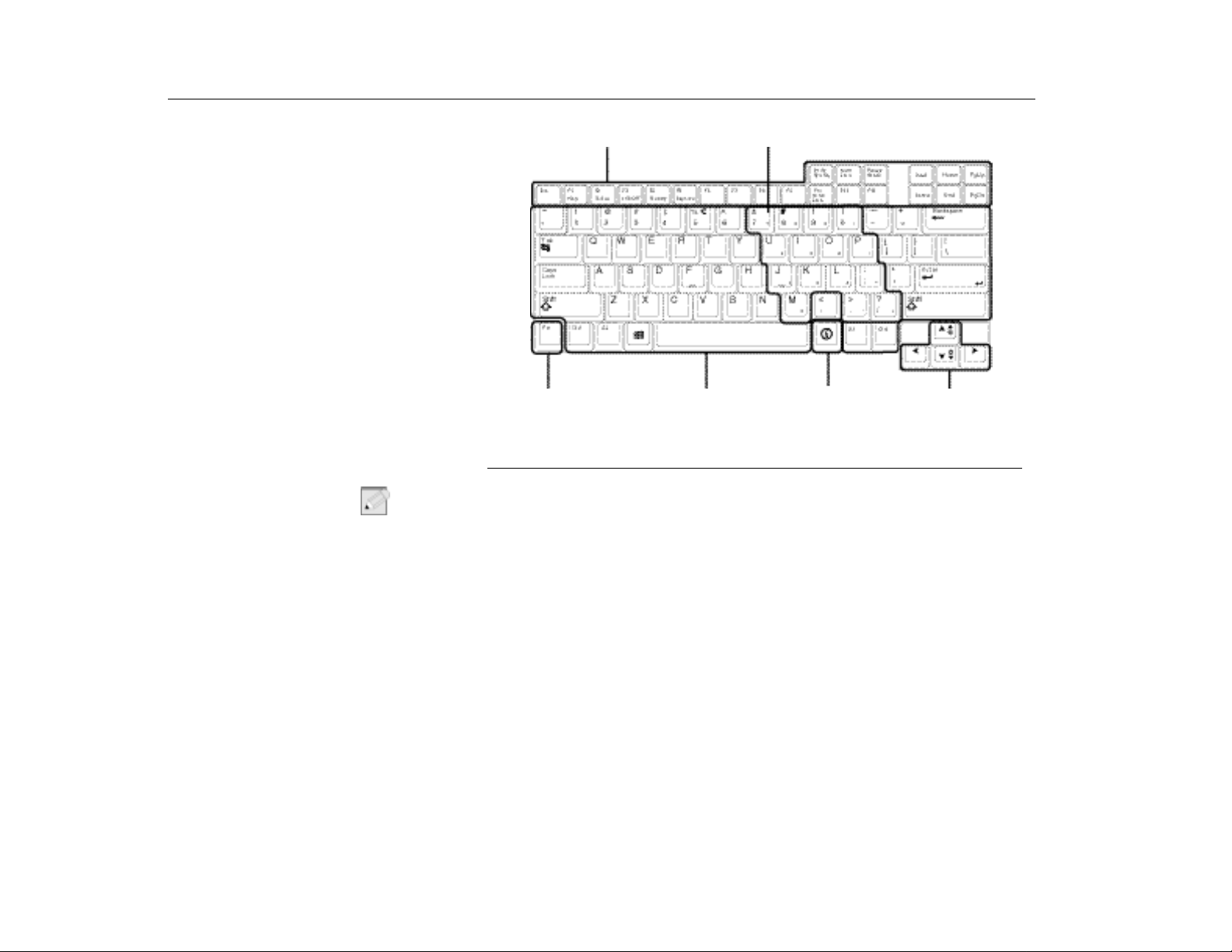
Your computer has an 87 key keyboard (Figure 6). By pressing designated key
combinations, you can have access to all the key functions of a full-sized
keyboard.
25
Page 26
Introducing Your TransPort LT
Using the Keyboard
N
OTE
Function and Special Purpose Hotkeys
Function Key
Figure 6. Keyboard
Although the layout of the keys on your computer’s keyboard is different from that
:
Alphanumeric
Keys
Embedded Numeric Keypad
Internet Key
Cursor and Screen
Control Keys
of a desktop computer’s keyboard, the keyboard feels like a full-sized keyboard
when you use it. The distance between the keys (the pitch) is the same as on a
full-size keyboard (19 mm).
26
The keys on the keyboard can be grouped into the following categories:
•
Full-sized Alphanumeric typewriter keys are arranged like a standard
typewriter keyboard and are used for text entry. The Windows keys on the
left side of the spacebar open the Windows
menu and perform other
Start
special functions. The Internet key on the right side of the space bar is
used to start your Internet browser.
•
Function keys, when pressed together with the [Fn] key, enable special
functions.
•
Cursor and Screen control keys move the cursor. They may perform other
functions, depending on your software.
Page 27

Introducing Your TransPort LT
Using the Keyboard
Using the Embedded Numeric
Keypad
Your keyboard includes a numeric keypad, which is a group of keys that you can
set to type numbers and mathematical symbols, such as the plus sign (Figure 7).
A number or symbol on the right corner of each keypad key shows its numeric
function.
Figure 7. Numeric Keypad
Press [Num Lock] to turn on the embedded numeric keypad. The numeric
functions of the keypad are enabled and the Num Lock li ght tur ns on. (See
”System Status Lights” on page 29 for the location of the Num Lock light.)
While the numeric functions are enabled, you can temporarily return a key to its
normal function by pressing [NumLock].
To turn the numeric keypad off, press [Num Lock] again. The Num Lock light turns
off.
Using Special Function Keys
The [Fn] key activates special functions when it is pressed in combination with
another key. Table 1 shows the special key combinations.
TABLE 1. Description of Special Function Keys
[Fn] Key
Combination
[Fn+F2]
[Fn+F3]
Function
Displays the battery gauge in the upper-right corner of
Status:
your screen. The gauge closes in a few seconds, or you can
press [Esc] to close the gauge. (See ”Using the Battery Gauge”
on page 44 for more information on the battery gauge.).
LCD/CRT:
monitor, and simultaneous display on both the LCD and the
external monitor.
Switches the display between the LCD, the external
27
Page 28
Introducing Your TransPort LT
Using the Touchpad
Using th e Touchpad
N
OTE
[Fn+F4]
[Fn+F5]
[[Fn+F10]
[Fn+up
Arrow]
[Fn+down
Arrow]
:
When you press a function key combination, the system sound may be
Standby:
normal operation from standby, press the power button.
KeyLock:
Type your password and press [Enter] to unlock the keyboard.
The [Fn+F5] key combination has no effect unless a password is
enabled and Password on boot is enabled in System Setup. The
Num Lock, Caps Lock, and Scroll Lock lights blink when the
keyboard is locked.
Scroll Lock:
scroll the page up or down while the cursor position does not
change. Pressing [Fn+F10] again turns off the scrolling function.
Brightness up:
Brightness down:
Puts the computer into standby mode. To resume
Locks the keyboard and activates password protection.
In some applications, sets the cursor-control keys to
Increases the LCD brightness.
Decreases the LCD brightness.
temporarily muted or repeat.
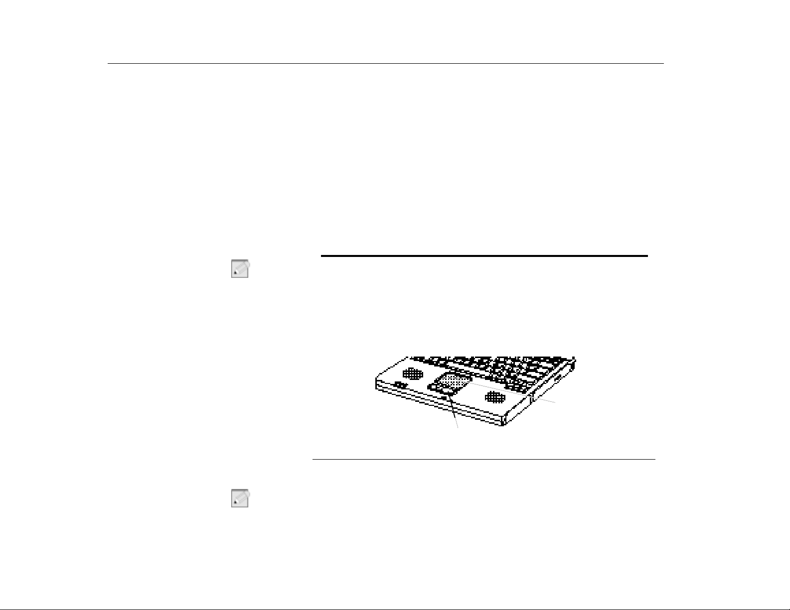
Your computer is equipped with a touchpad, which is an integrated-pointing
device that is used to perform standard mouse functions (Figure 8). The touchpad
is an advanced and reliable pointing device that works with the touch of your
finger.
28
N
OTE
Touchpad
Mouse buttons
Figure 8. Using the Touchpad
Table 2 explains how to use the touchpad.
:
Press on the touchpad gently. The touchpad responds to light pressure.
Page 29
Introducing Your TransPort LT
Reading the System Status Lights
TABLE 2. Using the Touchpad
Mouse Action How To
Move cursor Place your finger on the touchpad and slide your finger
in the direction you want the cursor to move. The faster
you move your finger, the faster the cursor moves
across the screen.
Click Tap the touchpad once with your finger.
Double-click Tap the touchpad twice with one finger.
Scroll up/down Place you finger on the right hand side of the touchpad
and slide it up or down to scroll the current window.
Scroll left/right Place you finger on the bottom of the touchpad and
slide it left or right to scroll the current window.
You can use the buttons below the touchpad in the same way you would use
standard mouse buttons. For more information on these features and other
features supported by your mouse driver such as button assignment, see the
Mouse
properties in the
Control Panel
.
For information on attaching and using another pointing device or keyboard with
your Transport LT, see “Connecting Peripheral Devices” on page 31.
Reading the System Status
Lights
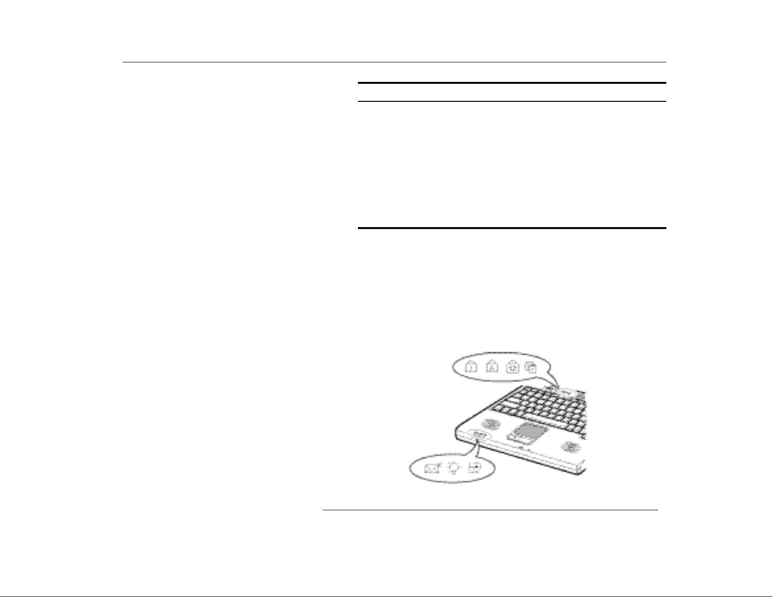
System Status lights show the status of computer functions. The lights appear on
the left edge of the computer and left side of the power button (Figure 9).
Figure 9. System Status Lights
29
Page 30
Introducing Your TransPort LT
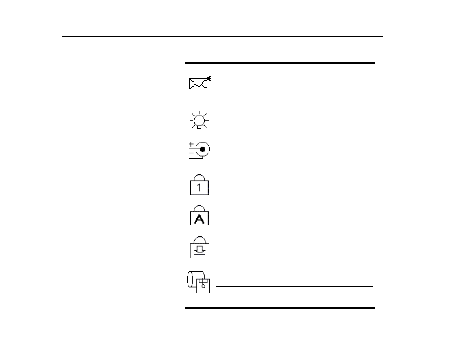
Table 3 describes the meaning of the lights.
TABLE 3. System Status Lights
Icon Function of Light
: Light is on when e-mail arrives.
E-mail
To enable this function, you need to register your E-mail Account in
the
Register E-mail Account
StartUp
currently only available in WIndows 98.
Power light:
>
Internet Launcher
Light is green when the computer is on.
window. Select
Reading the System Status Lights
Start >Program
to register an E-mail account. This is
>
Battery charge light:
indicates the battery’s charge status. The light is amber when the
battery is charging normally. The light is green when the battery is
fully charged. (See ”Charging the Battery” on page 41 for more
information about charging the battery.)
Num Lock light:
is activated. See ”Using the Embedded Numeric Keypad” on page
27 for a description of the keypad.
Caps Lock light:
activated. When the function is activated, all alphabetic characters
you type will be in upper case.
Scroll Lock light:
activated. The scroll lock function affects cursor movement and text
scrolling in some applications. This is a software specific function.
Refer to the appropriate software manuals for a description of the
[Scroll Lock] key.
Drive light:
accessed. Do not turn your computer off when this light is on. When
the light is amber, the fl op py d r ive is being accessed. When the l igh t
is green, the hard drive is being accessed. For a CD-ROM or DVDROM drive, check the light on the drive itself to see if the drive is
being accessed.
The light is on when the hard drive or floppy d rive is be ing
When the power cord is connected, the light
The light is on when the embedded numeric keypad
The light is on when the caps lock function is
The light is on when the scroll lock function is
30
Page 31
Introducing Your TransPort LT
Connecting Peripheral Devices
Connecting Peripheral
Devices
AUTION
C
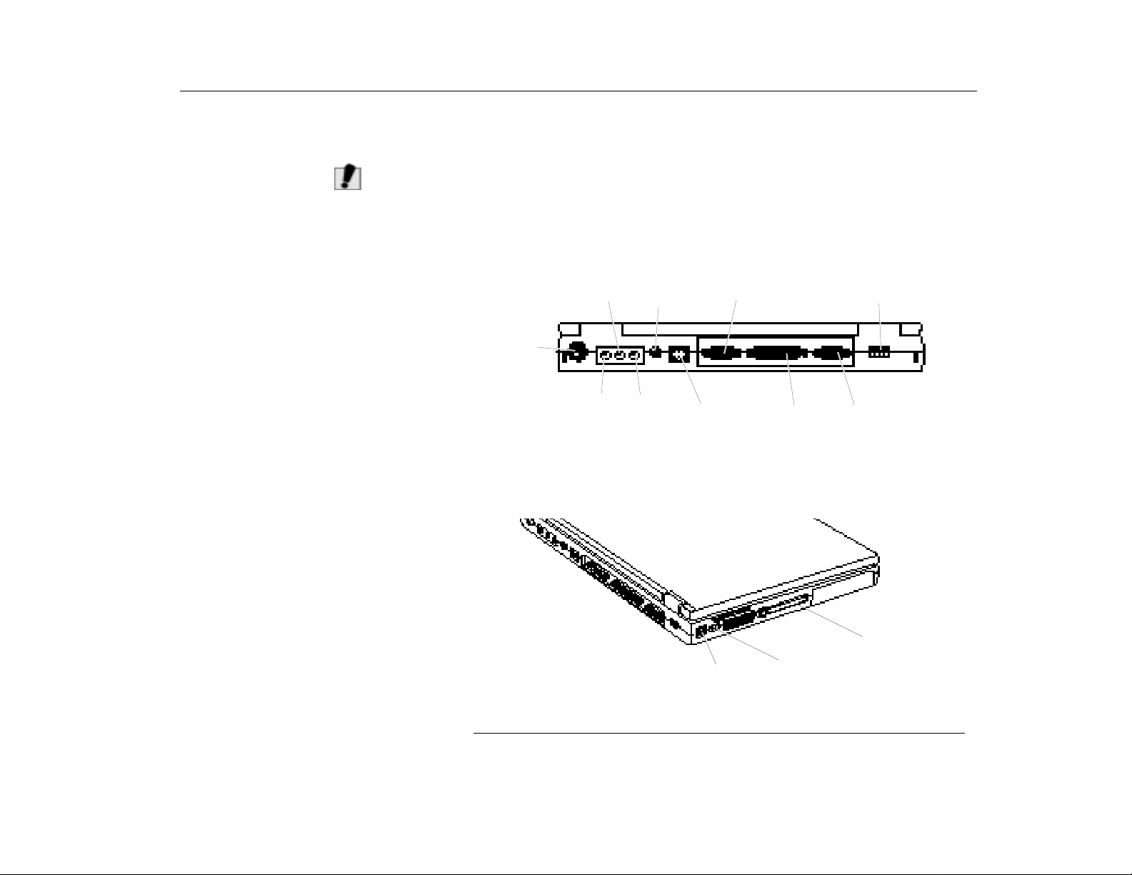
The connectors on your computer enable you to attach peripheral devices to the
computer (Figure 10).
Turn off your computer before you connect a peripheral device. Connecting
:
a peripheral device with your computer turned on may seriously damage the
device or your computer and may void the warranty.
PS/2™
mouse and
keyboard
port
Line-in
Microphone
jack
Power
Connector
Headphone
jack
Serial port
LAN port
(Optional)
Parallel port
USB port
Video port
Figure 10. Peripheral Connectors
PC Card (PCMCIA
Slot
Infrared port
Modem jack
31
Page 32
Introducing Your TransPort LT
Connecting Peripheral Devices
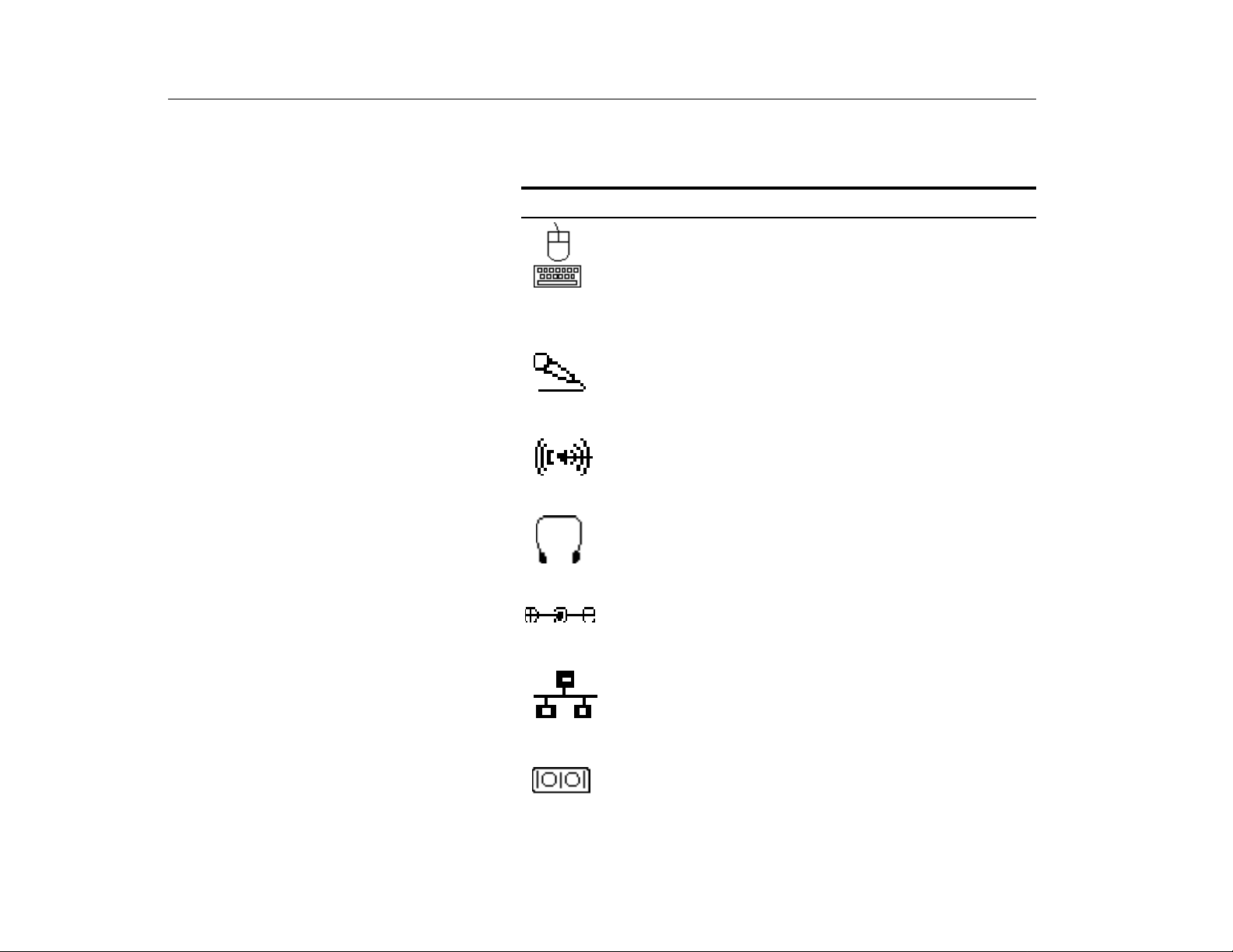
Table 4 shows the icons located near each connector and describes the devices
that you can attach to the connectors.
TABLE 4. Connecting Peripheral Devices
Icon Connector
PS/2 (Personal System/2) mouse and keyboard port:
PS/2-compatible mouse or external keyboard or keypad to this
port. Make sure your computer is turned off when you attach
peripherals to the port.
You can use the computer’s touchpad and a PS/2 keyboard at the
same time, see PS/2 Mouse Configuration in the “Advanced
Menu” on page 81 for more information
Microphone jack:
microphone connected to this jack overrides the internal
microphone.
Line-in jack:
Headphone jack:
jack. Speakers connected to this jack override the internal
speakers.
Power connector: Plug in the AC adapter to run the computer and
charge the battery, see “Connecting the AC Adapter” on page 19.
LAN (Local Area Network) port (Optional):
this port.
Connect an external microphone to this jack. A
An input for external audio.
Connect stereo headphones or speakers to this
Connect LAN cable to
Connect a
32
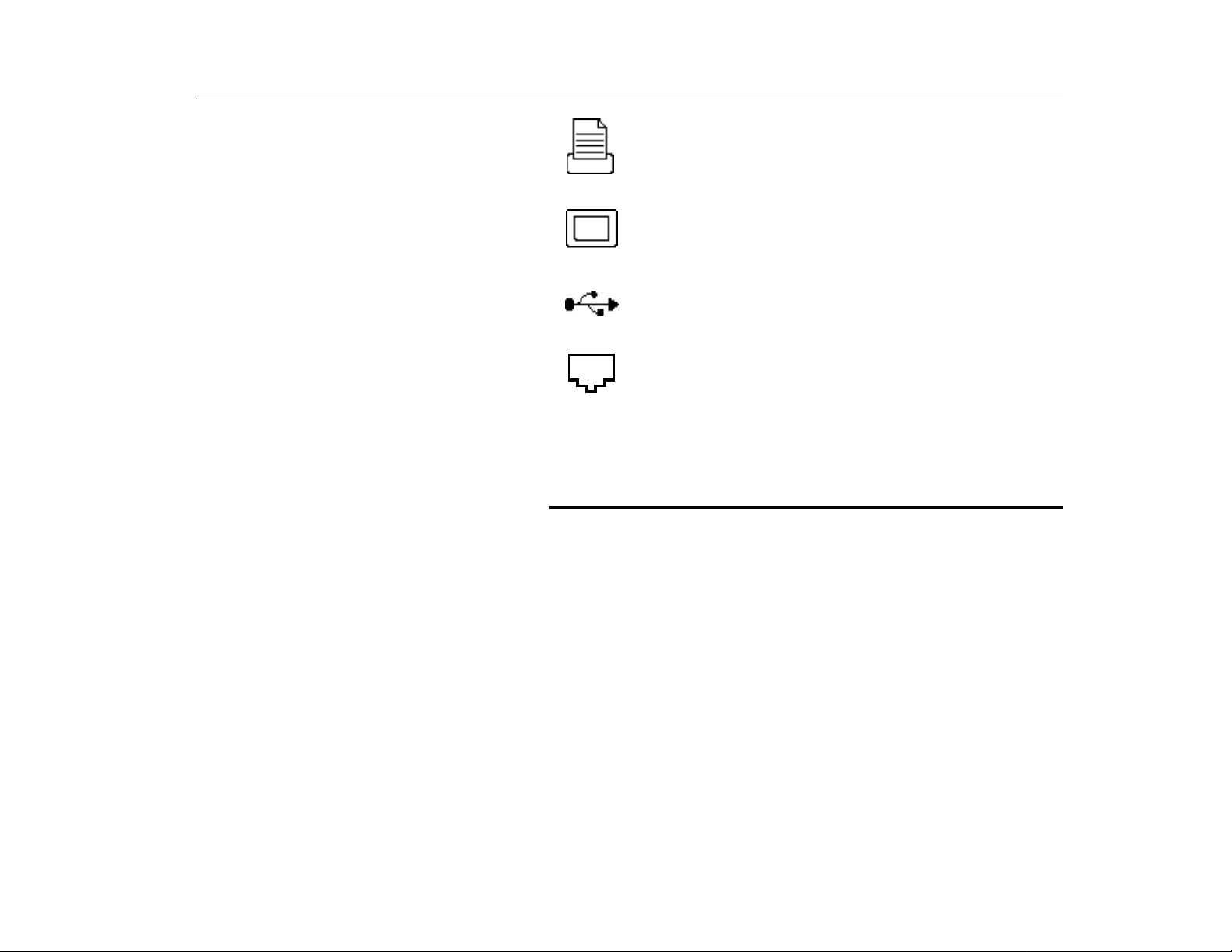
Serial port:
pin port. If the device has a 25-pin connector, you need a 25-to-9pin serial adapter.
Plug a serial devi ce, such as a ser ial mo us e, i nto thi s 9-
Page 33
Introducing Your TransPort LT
Using the Flex-Bay
Parallel port:
network adapter, into this 25-pin port.
Video port:
15-pin connector and then plug the monitor power cord into a
grounded outlet.
USB (universal serial bus) port:
USB input/output devices include keyboards, pointing devices,
monitors and external FDD module.
Modem jack:
send/receive faxes, see “Using the Modem” on page 46 for more
information.
Port Replicator:
connector. See ”Port Replicator” on page 68 for more information.
Plug a parallel device, such as a parallel printer or
Plug the interface cable of an external monitor into this
Connect USB devices to this port.
Connect a telephone line to c onnec t to the Intern et or
Connect a port replicator (Optional) to this
If your computer’s Operating System is Windows 98 or Windows 2000, you can
use the USB port. The Windows NT 4.0 Operating System does not support USB.
Using the Flex-Bay
Your computer includes the Flex-Bay, a peripheral bay that can hold one of the
following devices:
•
Floppy disk drive
•
CD-ROM drive: shipped with some computers and also available as an
option.
•
DVD-ROM: shipped with some computers and also available as an option.
•
Optional secondary battery: available as an option for your computer.
•
LS-120: available as an option.
33
Page 34
Introducing Your TransPort LT
C
AUTION
Using the Flex-Bay
:
If your Operating System is Windows 98, you can use the SmartBay Utility
to hot-swap the devices. If you do not use Windows 98, make sure that the
computer’s power is off before you remove or install any devices.
T o Remove a Device fr om the FlexBay
To Install a Device in the Flex-Bay
1. Turn the computer’s power off.
2. Close the LCD panel, and turn the computer over so that the bottom of the unit
faces up.
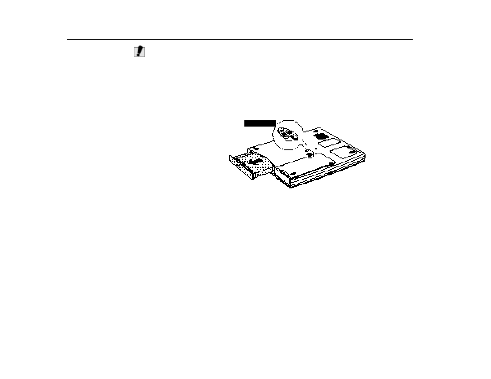
3. Pull up on the Flex-Bay latch and pull the device from the bay (Figure 11).
Flex-Bay latch
Figure 11. Removing a Device from the Flex-Bay
4. Remove the device out of the bay.
1. Turn the computer off.
2. Place the device into the bay.
3. Push the device in until it is flush with the chassis.
4. Push down on the Flex-Bay latch until the latch snaps into place.
Your computer’s Operating System automatically recognizes the device in the
Flex-Bay and configures your computer accordingly.
Using the SmartBay Utility
34
If your computer shipped with Windows 98, you can use the SmartBay utility to
hot-swap your devices in the flex-bay. Currently SmartBay is not functional in
Windows NT and Windows 2000.
Page 35

Introducing Your TransPort LT
Using the Floppy Drive
To start the SmartBay utility
1. Click the
2. Select
To remove a device:
1. Open the
2. Select
3. Click
4. Remove the device by either disconnecting the cable from the computer or
from the device.
5. Click OK.
To insert a device:
1. Open the
2. Select
3. Connect the device to the computer using the device cable. Make sure all
connectors are correctly attached.
4. Click OK to allow your computer to detect the device.
If the computer does not detect the device, remove the device and re-install it.
Make sure to pay careful attention to the procedures to insure the device is
installed correc tl y.
Start
button on the Windows taskbar.
SmartBay Hotswap Utility
SmartBay Hotswap Utility
Remove Device
Yes
on the confirmation screen
SmartBay Hotswap Utility
Insert Device
:
.
.
and click OK.
.
and click OK.
Using the Floppy Drive
N
OTE
Your computer comes with a 1.44 MB, 3.5-inch, high-density floppy drive, which
can read, write to, and format the following disks:
•
A high-density, 3.5-inch disk, which stores 1.44 MB (megabytes) of data.
•
A double-density, 3.5-inch disk, which stores 720 KB (kilobytes) of data.
The floppy drive in your notebook computer is smaller, but more power-efficient,
:
than a floppy drive in a desktop computer. To get the best performance from your
floppy drive use high-quality floppy disks, such as those available at http://www.eadditions.com.
The computer is shipped from the factory with both a floppy drive and a CD-ROM
or DVD-ROM drive included.
35
Page 36
Introducing Your TransPort LT
C
AUTION
Using the Floppy Drive
:
The external USB FDD Drive is recognized as the last drive. For example,
the drive letter will be E: in case the CD-ROM drive is installed into Flex Bay.
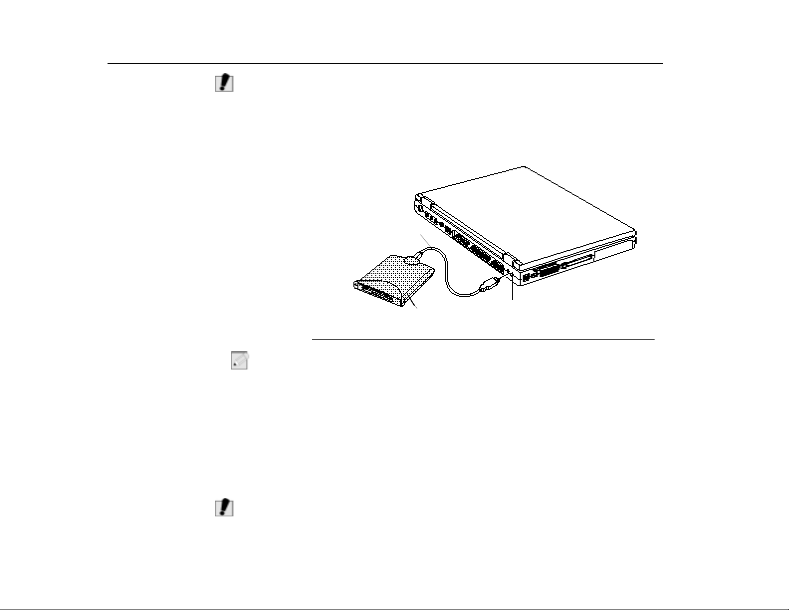
To use the floppy drive and the CD-ROM at the same time, install the CD-ROM
drive in the Flex-Bay. Then attach one end of the USB cable to the floppy drive
compartment and the other to the external USB port on the computer. (Figure 12)
The USB Floppy Drive is an optional item in Windows 98 and WIndows 2000.
Cable
36
N
AUTION
C
OTE
Floppy drive
Figure 12. Inserting a Floppy Disk
:
If you want to use the floppy disk drive within the computer, then detach the floppy
USB port
disk drive from the external FDD drive compartment and insert the floppy disk
drive into the Flex-Bay. See ”Using the Flex-Bay” on page 33.
The floppy drive light is on when the computer writes to or reads from a floppy
disk. Do not remove a disk when this light is on.
To protect the data on your floppy disks, follow these guidelines:
•
Keep disks away from excessive heat, direct sunlight, and liquids.
•
Keep magnets and any device that contains a magnet (like the telephone)
away from your disks.
:
Magnetic fields can destroy the information on a disk.
Page 37
Introducing Your TransPort LT
Using the CD-ROM Drive
•
Do not write directly on a label on your disk; instead, write on a disk label
first and then attach the label to the disk.
•
Make copies of all your important disks.
Using the CD-ROM Drive
AUTION
C
Compact Disc Drives are designed so that you can easily insert one into the
computer when you need it, and then remove it. See ”Using the Flex-Bay” on
page 33 for information on installing the CD-ROM drive into the Flex-Bay type
computer.
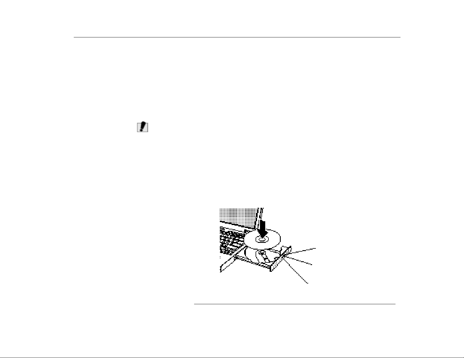
1. Press the button on the CD-ROM drive, and the tray slides out. (Do not lean on
the tray; it does not support much weight.)
If the tray fails to slide out it may be stuck, in which you can use the
:
emergency eject button to open the CD-ROM. Turn the computer’s power
off. Straighten out a paper clip (or some other similar object), insert it into
the small hole in the front of the CD-ROM to press the button. The CD-ROM
should eject.
2. Insert a CD (compact disc), label side up (or remove a disc, if you have
finished using it).
3. Push the tray in gently to close the drive tray (Figure 13).
A light on the drive tray is on when the computer is reading from a CD. Do not
remove a disc when this light is on.
Figure 13. Using the CD-ROM Drive
Emergency eject button
Eject button
CD-ROM Light
37
Page 38
Introducing Your TransPort LT
W
OTE
N
ARNING
Using the CD-ROM Drive
Install and start a CD-based program in the same way you would run a program
on a floppy disk. See your Operating System documentation for more information
on running programs.
The name of the CD-ROM drive is the letter following the letter assigned to your
last hard drive. For instance, if you have one hard drive with two hard drive
partitions, the hard drives are drives C and D and the CD-ROM drive is drive E.
:
Your Transport LT comes from the factory with the CD/DVD set as R:\.
:
Do not place reflective objects in the disc slot because of possible
hazardous laser emissions. The laser beam used in this CD-ROM drive is
harmful to the eyes. Do not attempt to disassemble the CD-ROM drive.
The on-board audio hardware and software of your computer enable the
computer to play audio compact discs. If you wish to do so, you can attach
external speakers to the Headphone jack.
To play an audio compact disc:
1. Insert a compact disc into your CD-ROM drive.
2. Press the button on the CD-ROM drive.
3. When the tray slides out, insert a CD, label side up.
4. Close the drive tray. The CD Player button appears on the task bar. The disc
begins to play.
A light on the drive tray is on when the computer plays a CD. Do not remove a
disc when this light is on.
38
Page 39
Introducing Your TransPort LT
Using the Hard Drive
To remove the CD:
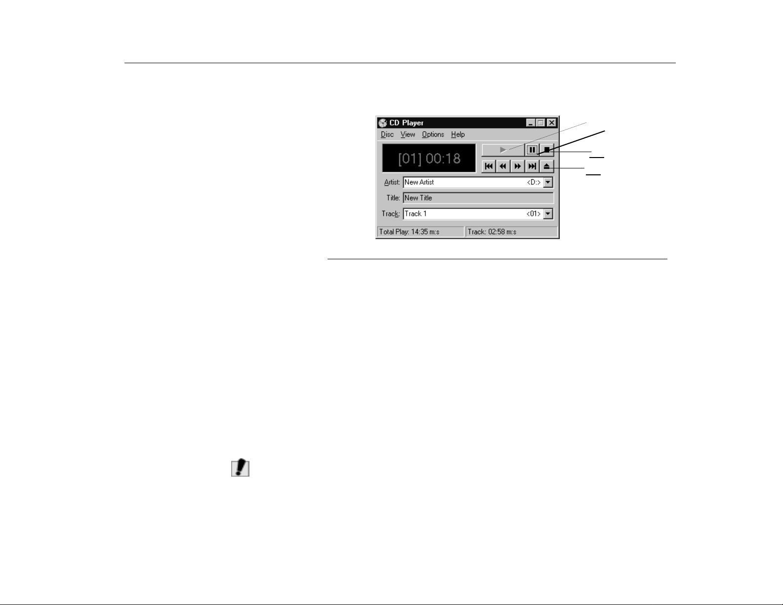
1. Click the CD Player button on the Windows task bar to open the CD Player
window (Figure 14).
Play
Stop
Eject
Figure 14. CD Player Window
Using the Hard Drive
AUTION
C
2. Click the
3. Click the
Stop
button in the
Eject
button on the
CD Player
CD Player
window.
window or press the button on your
CD-ROM drive. The drive tray opens and you can remove the disc from the
CD-ROM drive. For more information on playing compact discs, see the
menu in the
CD Player
window.
Your computer includes a removable IDE (integrated drive electronics) hard drive.
The IDE hard drive can store the data and programs your computer uses. The
drive plugs into a connector on the system board.
Although the storage capacity of hard drives vary according to the model, any
hard drive holds much more than a floppy disk does. Also, the computer reads
and works with a hard drive more rapidly than with a floppy disk.
Once information is saved on a hard drive, it remains there until it is overwritten.
Hard drive heads park automatically when you turn off your computer.
The hard drive that comes with your computer has already been formatted.
:
Do not format the hard drive. Doing so destroys all data contained on the
drive. If you need to format a new drive, or want to erase all data on your
existing hard drive, refer to the manual for your Operating System.
Help
39
Page 40
Introducing Your TransPort LT
C
Removing the Hard Drive
C
AUTION
AUTION
Using the Hard Drive
Although Windows 98 can work with FAT-16 or FAT-32 (a 32-bit file allocation
table), your computer has been supplied with FAT-32. Older software that you
may have (16-bit software) may require FAT-16 to run. Similarly, Windows NT 4.0
can use FAT-16 or NTFS (the Windows NT file system). There are utilities
included with Windows 98 and Windows 2000 to convert from FAT-16 to FAT-32
or NTFS (Windows NT 4.0 and Windows 2000), see the documentation included
with your Operating System for more information.
The MRestore disk includes Partition Magic that also allows you to convert
partitions. For more information, see “MRestore CD-ROM” on page 99.
:
It is not possible to convert from FAT-32 or NTFS to FAT-16 without
reformatting your hard drive.
:
To prevent loss of data and damage to the disk, do not remove the hard
drive while the computer’s power is on and do not drop or jar the h ard driv e.
To remove the hard drive from the computer:
1. If you are installing a new hard drive, backup the application and data files on
the old hard drive before removing it from the computer.
2. Turn the computer off.
3. Close the LCD panel, and turn the computer over so that the bottom of the unit
faces up.
4. Remove the screw that holds the hard drive in place (Figure 15).
40
Bottom of
computer
Hard-drive
Figure 15. Removing the Hard Drive
Page 41
Introducing Your TransPort LT
C
AUTION
5. Pull the hard drive out of the computer.
:
Only install a hard drive that is thinner than 9.5 mm in this computer.
Using the Battery
Installing a Hard Drive
Using the Battery
Charging the Battery
To install a hard drive:
1. Remove the old hard drive from the computer as described in the previous
section.
2. Slide the new drive into the hard drive compartment. Make sure the drive is
pushed back as far as it will go.
3. Install the screw that holds the hard drive in place.
4. If you intend to use save-to-disk mode, see “Creating a Save-To-Disk Partition”
on page 97.
5. Format your drive and reinstall your files. See ”MCRC (Micron Customer
Resource Center)” on page 99 for instructions on re-installing the Operating
System and drivers for your Transport LT notebook computer.
Your computer uses a smart rechargeable Lithium-ion (Li-ion) battery pack for
power when the AC adapter is not attached to an electrical outlet. The smart
battery gives an accurate measurement of the current battery capacity which
helps extend operating time by enabling effective power management in
Operating Systems that take advantage of the accurate information supplied by
the battery.
Your computer’s battery starts charging automatically when you connect the
power to the computer and to an electrical outlet. If the computer is off, the battery
charges faster than if the computer’s power is on.
Approximate charging times for Li-Ion (Ni-MH) battery are:
•
Two and a half (2.5) hours with the computer off.
•
Four (4) hours with the computer on.
While the battery is charging normally, the battery charge light on the computer is
amber (See ”System Status Lights” on page 29 for the location of the battery
charge light). When the battery is fully charged, the light changes to green.
41
Page 42
Introducing Your TransPort LT
N
OTE
Using the Battery
When you use a new battery pack for the first time or use a battery after a long
period of storage, the initial battery life is shorter than normal. Normal battery life
resumes after a few discharge-recharge cycles.
Follow these rules for charging your battery:
•
A battery normally discharges power when not used for long periods of
time. Be sure to recharge the battery every two months when it is not in
use.
•
Make it a practice to discharge your battery fully before recharging the
battery. This can help extend the life of the battery.
•
Do not attempt to charge the battery in temperatures of under 41
o
or over 95
:
All batteries eventually wear out and lose the ability to hold a charge. You may
F (35oC.)
need to replace your battery pack after a year of average usage.
o
F (5o C)
Safely Using th e B a ttery
Removing the Battery
42
Follow these guidelines to safely use the battery:
•
Turn off your computer and unplug it if you accidentally:
•
Expose the equipment to liquid.
•
Drop, jar, or damage the computer.
•
Do not disassemble the battery, heat it above 212° F (100° C), or burn it.
The battery used in this computer may cause a fire or chemical burn if
mistreated.
•
Your computer's rechargeable battery may be considered hazardous
waste. If you replace your battery with a new one:
•
Keep the old battery out of the reach of children.
•
Dispose of the old battery promptly.
•
Make sure that you follow all local requirements when you dispose of
the old battery.
Your computer comes with the battery pack inserted in the computer. To remove
the battery from the computer:
1. Turn the computer off.
Page 43
Introducing Your TransPort LT
y
Using the Battery
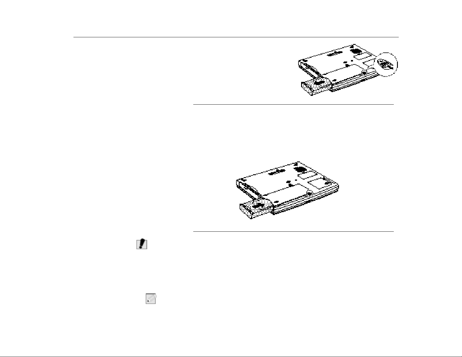
2. Close the LCD panel, and turn the
computer over so that the bottom of
the unit faces up.
3. Push down the battery latch and
hold it, then pull the battery pack
from the computer. (Figure 16)
Figure 16. Removing the Battery Pack
Installing the Batter
AUTION
C
Monitoring the Battery Charge
To install the battery pack:
1. With the computer’s power off, close the LCD panel and turn the computer
over so the bottom of the unit faces up.
2. Slide the battery pack into the compartment. Make sure the battery is fully
inserted into the compartment.
Figure 17. Installing the Battery
Insert the battery into the battery compartment, ensuring the correct
:
orientation so that the battery fits in its slot properly.
Battery life is effected by factors such as the power-management settings in
System Setup, the applications you use, and the brightness settings of the LCD.
Under normal usage, the battery charge lasts approximately two and a half hours.
N
OTE
Battery life estimates are subject to variation. The actual life of your battery may
:
be less than the estimates given in this manual.
43
Page 44
Introducing Your TransPort LT
Using the Battery
You can monitor the charge of the battery pack installed in your computer through
the battery gauge.
Using the Battery Gauge
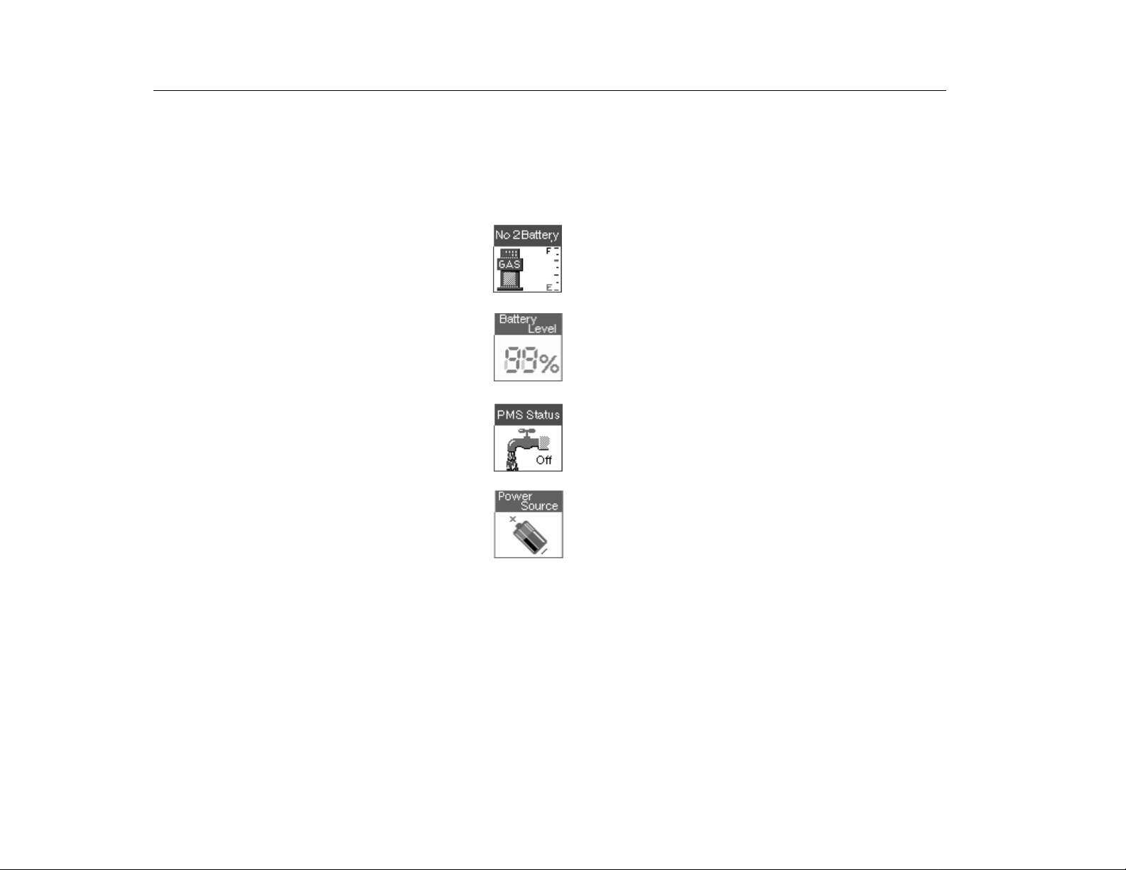
Press [Fn+F2] to display the battery gauge on the LCD. You can display the
battery gauge while you are in any program.
The gauge has four sections:
•
The top/left section of the gauge indicates whether the
secondary battery is used or not. If it is used, the two digit
decimal number that represents the status of secondary
battery charge remaining.
•
The top/right section indicates the approximate
amount of the primary battery charge remaining.
•
The bottom/left section of the gauge shows you
current PMS (Power management Setting) status which
is set in the system setup. It shows
adapter is plugged in.
•
The bottom/right section indicates whether the
computer is being powered by the battery or by the AC
adapter. An icon of a power cord plug indicates an
internal AC adapter power source and a battery icon
(shown) indicates a battery power source.
Off
when the AC
Using PowerProfiler to Monitor
the Battery
44
While the battery gauge is displayed, all keys except [Esc] are disabled. The
battery gauge closes in a few seconds, or you can press [Esc] to close it.
Use PowerProfiler to set power-management options for computers shipped with
Windows NT installed. To use PowerProfiler to monitor the battery charge, place
the cursor on the battery icon in the right corner of the task bar. PowerProfiler
shows you the amount of battery charge remaining.
Page 45

Introducing Your TransPort LT
Using the Battery
To set battery monitoring options in PowerProfiler:
Battery Warnings
1. Double-click the
2. Click the
Battery
3. Set options under
PowerProfiler
battery icon to open the software.
tab.
Battery Status and Alarm Settings
.
For more information on PowerProfiler, see the Help option in the PowerProfiler
software.
Your computer gives you the following low-battery warnings (Table 5).
TABLE 5. Battery Warnings
Warnings Condition Action to Take
The computer beeps 5
times.
The computer beeps 5
times, with a short time
between beeps. After a
short time, the comp uter
automatically goes into
rest mode.
Battery low: The battery
charge is about 10
percent. Approximately
5–10 minutes of battery
charge is left.
Battery very low: The
battery charge is about 5
percent.
Save your work. Use the
power cord to power the
computer or turn off the
computer and i nstall a fully
charged battery.
Use the power cord to
power the computer and
charge the battery.
When DVD-ROM is installed, computer doesn’t dee.
The above features are valid with Windows 95/98 APM compliant Operating
Systems. In the case of a Windows 98 or any other ACPI compliant Operating
System which is running on APM interface, you should adjust the battery alarm
features by using the Operating Systems power management program (Control
Panel > Power management in Windows 98).
Windows 98 and WIndows 2000 can operate in APM or ACPI mode, in the APM
mode you should select the Rest mode of the low battery situations (Power On
Suspend/Save-to-Disk) in BIOS setup. See “Power Menu” on page 84.
If you cannot run your computer from the battery and the battery will not charge
when you attach the power cord, the problem may be that:
45
Page 46
Introducing Your TransPort LT
Using the Modem
•
The battery temperature is below 41° F (5° C) or over 95° F (35° C). If you
think the battery temperature is too hot or too cold, turn off the computer,
remove the battery, and let the battery reach room temperature. Then try
charging the battery again.
•
The battery is defective. Replace the battery with a new battery.
Using the Modem
Precautions Before Use
N
ARNING
W
Using the modem on a PBX system
(Key-phone system)
OTE
All TransPort LT notebooks ship with an internal modem installed. The
combination Modem/NIC is optional.
The Transport LT Modem with a PCI interface does not support DOS mode. You
:
can use DOS box in Windows 98 instead of pure DOS mode.
If you connect the modem to the digital key-phone line, the modem will be
:
damaged.
If you use a simple terminal program
command as an initializa tio n comm and .
If you use a
1. Click the
2. Click
3. Double-click the
tab.
4. Check the
tab.
Windows Communication Program
button and then point to
Start
Control Panel
Wait for dial tone before dialing
.
Modems
icon and the click
you should type
follow the instructions below.
Settings
.
Properties
check box at the
ATX3&W
button at the
or
ATX3
Connection
General
46
Page 47
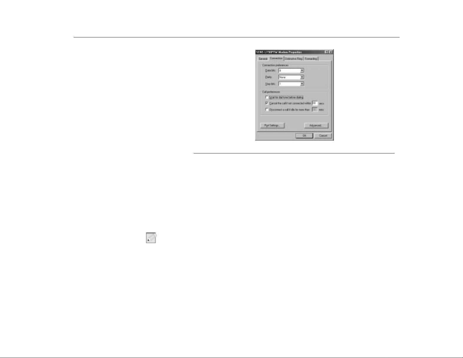
Introducing Your TransPort LT
Figure 18. Modem Properties Dialog Box
5. Click OK to close the dialog box.
6. Click OK to close
Modem Properties
Using the Modem
dialog box.
Description of 56K
N
OTE
There are different standards regarding 56K technology.
•
K56Flex
Technology developed by Rockwell Semiconductor Systems and Lucent
Technologies
•
X2
Technology developed by USR (US Robotics, now 3Com)
K56Flex and X2 are not interoperabl e.
:
•
V.90 Standard.
In February 1998, The ITU-T (ITU Telecommunication Standardization
Sector) agreed on the technical specifications for 56K modems (V.90) and
has approved in mid-September, 1998. But, the modem driver can be
updated to resolve fine points of operation between different vendor's
modems and unusual telephone line conditions.
47
Page 48
Introducing Your TransPort LT
N
OTE
Using the Modem
:
1. Due to FCC limitations, speeds of 53kbps are the maximum permissible
transmit power levels during download transmissions. Actual data speeds will vary
depending on line conditions.
2. In order to use the 56K feature, be sure to check if the standards supported by
the on-line service provider and the modem are identical.
If you use a PBX phone system, you cannot connect using the 56K mode due to
line loss.
Modem Specifications
•
Data communications.
•
V.90, K56Flex, V.34+, V.34, V.32bis, V.32, V22bis, V.22, V.21,
BELL212A, BELL103
•
Data throughput speed
•
56,000 bps ~ 28,000 bps (V.90, downstream only, step: about 1333
bps)
•
56,000 bps ~ 32,000 bps (K56Flex, downstream only, step: 2000 bps)
•
33,600 bps ~ 2,400 bps (step: 2400 bps)
•
1,200 bps
•
300 bps
•
Fax mode support.
V.29, V.27ter, V.21ch2, V.17
•
Fax throughput speed.
14400, 12000, 9600, 7200, 4800, 2400, 300
•
Data compression feature.
V.42bis, MNP CLASS 5
•
Data correction feature.
V.42 LAPM, MNP CLASS 2~4
•
Fax capacity.
CLASS 1
•
Plug and Play feature.
Microsoft Windows 95/98 Plug and Play Support
•
PCI 2.1, PPMI 1.0 support
48
Page 49

Introducing Your TransPort LT
Installing the Modem Driver in Windo ws 95/9 8
Installing the Modem
Driver in Windows 95/98
Modem Commands
What are AT commands?
Before Using AT Commands
You can install the modem drive as shown in the following instructions. Refer to
the MRestore CD that comes with your Transport LT for Modem installation
instructions for your Operating System.
The Transport LT Modem includes the basic commands used by the Smart
Modem of the Hayes Corporation. Additional commands are added to improve its
capacity.
AT commands are the control commands of Fax modems developed by the
Hayes Corporation. AT commands are the industry standard and are necessary
for any fax modem. It is used with S-register to set the modem status.
Generally, AT commands are used by directly entering the command into any
communications program, like Hyper terminal.
You can perform the following functions more easily by using AT commands.
•
Calling up or hanging up the phone in order to communicate by computer
modem.
•
Choosing a modem in order to make the most efficient communication
status.
Communication programs are becoming more efficient and more intelligent, and
users do not need to know all the AT commands. Knowing a few basic commands
is enough for computer communications.
To use AT commands, enter them into terminal-based communication programs
directly. (Hyper terminal within Windows 98 and Windows NT, and third party
communication programs like CrossTalk and Procomm.)
CompuServe and America On-line applications are not terminal-based
communication programs, but they are communication programs based on
Graphic environment. These programs, and those like them, can initiate the
modem setting by entering an AT command in a menu with a modem initialization
command.
Before using AT commands you have to know there are two kinds of modes when
you use it.
49
Page 50
Introducing Your TransPort LT
Installing the Modem Driver in Windo ws 95/9 8
Command Mode
If you turn on your computer and start communication by a communication
program, you can see a prompt on the terminal screen. Under such conditions,
you can use AT commands like calling, etc.
DATA Mode
In command mode, you can call by using AT commands and communicate with
others by connecting to other modems. You can call this status Data mode or Online mode. In data mode, you cannot use any AT commands except the +++
command, which has +++ at the head.
If you stop communication and disconnect the phone, the Fax modem will run in
command mode again.
Using Command Mode during Communications
Sometimes, you have to use AT commands while you're communicating with
others via modem. In this case, you can use +++ commands for AT commands
without hanging up your telephone. Pressing '+' three times makes fax modem
change to command mode. The telephone will not be disconnected. (Do not press
the [Enter] key after input +++).
Using AT commands
50
AUTION
C
AUTION
C
If you want to return to Data Mode, the connection may be lost depending
:
on the server.
If you want return to Data mode from command mode, you only have to input ATO
and press the [Enter] key to start the communications again.
The mode cannot be transferred from the command mode to the data mode
:
depending on the server.
AT commands can be used in the following way. There's no difference between
capital letters and small letters, and all commands should include 'AT' as a prefix
except ones which include 'A/' instead.
Also, Carriage Returns saved in the S3 register should be entered in order to
signal the end of the command.
AT command - press the [Enter] key.
Example: ATDT 123-4567 - press [Enter] and the modem dials to 123-4567.
Page 51

Introducing Your TransPort LT
Installing the Modem Driver in Windo ws 95/9 8
Display the result value
After entering AT commands, the result value is displayed on the screen.
The result value can be displayed during communication. Generally, the result will
be OK. According to the ATV command, the result can be displayed as Words or
numeral letters. (ATVO: Display as numeral letters, ATV1: Display as English
words).
Basic AT Commands
A/ Repeats the previous command in the buffer
ATA Responds manually to incoming RING signals
+++ Switches from on-line mode to command mode
ATO Switches from command mode to on-line mode
ATEn Echo control
E0 Disables echoing of the commands to the screen
E1 Enables echoing of the commands to the screen
ATDT phone number
Touch tone dial
ATDP phone number
Pulse dial
ATHn Hook control
H0 On-Hook (same as hang-up)
H1 Off-Hook (same as hold-on)
ATLn Modem speaker loudness control
L0~1 Low volume
L2 Medium volume
L3 High volume
ATMn Modem speaker control
M0 Disables modem speaker
M1 Enables only when in connection procedure
51
Page 52

Introducing Your TransPort LT
Installing the Modem Driver in Windo ws 95/9 8
M2 Enables always
M3 Enables until carrier has been detected after connection
ATS0=nSets S0 register value (n range: 0~255). Sets the number of incoming ring
signals before answering. The Modem responds after as many incoming rings as
specified in n value. If the value of n is '0', ATA command should be entered for
auto answer.
ATS0? Displays S0 register value on the terminal
ATX3 Dials after waiting for specified time
ATX4 Dials after dial tone is detected
ATZ Initializes modem
AT&F Loads the factory default configuration (profile)
AT&V Shows current configuration
AT&W Saves user profile
AT&Zn=xStores the dial string in modem memory (n=0~3, x=phone number) e.g.)
AT&Z0=1235678
Automatically calls the stored phone number by using the following command.
ATDTS0 Recalls the stored phone number as AT&Z0 by tone dial
ATDPS0 Recalls the stored phone number as AT&Z0 by pulse dial
AT+MS=X Sets protocol for modem connection
52
(X=V90, V34)
AT+MS=V90 (default setting)
Try to connect with V90 (max 56 Kbps)
AT+MS=V34
Try to connect with V.34 (max 33.6 Kbps)
Page 53

Video Features and Configuration
Chapter 4 - Video Features and Configuration
Your computer includes a TFT LCD or active-mat rix display. The capabilities of
the screen plus the video drivers installed on the computer determine the quality
of the image your LCD can display.
The following sections describe the display capabilities of your computer.
Resolution and Color Depth
Resolution and Color
Depth
The resolution of the LCD is the sharpness of the image it can display. Resolution
is measured by the number of pixels (individual dots) displayed on the entire
screen. In general, the more pixels the LCD can display, the better the image.
Your LCD screen is 12.1 SVGA, with a maximum display of 800x600, about
800,000 pixels.
The number of colors the LCD can display is measured by how many bits the LCD
uses to represent each pixel:
•
8-bit color can support 256 different colors.
•
16-bit color can support 64 K (65,536) colors.
•
24-bit color can support 16 M (16.8 million) colors.
•
32-bit color can support 16 M (16.8 million) colors.
24-bit color uses the RGB color model.
32-bit color uses the CMYK color model which gives better printed color matching.
Table 6 lists the basic video mode capabilities and maximum colors supported by
your computer.
53
Page 54
Video Features and Configuration
Resolution and Color Depth
TABLE 6. Video Driver Capabilities
Software
Drivers
Windows 98 640x480, 720x480, 800x600, 848x480, 1024x768,
Windows NT
4.0
Resolution Supported with 4MB(8MB) SGRAM
1152x864, 1280x1024, 1600x1200
640x480, 720x480, 800x600, 848x480, 1024x768,
1152x864, 1280x1024, 1600x1200
640x480, 720x480, 800x600, 848x480, 1024x768,
1152x864, 1280x1024, (1600x1200)
640x480, 720x480, 800x600, 848x480, 1024x768,
1152x864, (1280x1024)
640x480, 800x600, 1024x768, 1152x864,
1280x1024, 1600x120 0
640x480, 800x600, 1024x768, 1152x864,
1280x1024, 1600x120 0
640x480, 800x600, 1024x768, 1152x864,
1280x1024, (1600x1200)
640x480, 800x600, 1024x768, 1152x864,
(1280x1024)
Number of
Colors
256
65,536
16.8 million
(24 bit)
16.8 million
(32 bit)
256
65,536
16.8 million
(24 bit)
16.8 million
(32 bit)
All these video modes can be displayed on an external monitor. However, if you
disconnect an external monitor that was attached to your computer and then start
the computer, the LCD may revert to a different resolution than the one you chose
for the external monitor.
Configuring Display Features
Selecting a Monitor Type
54
The following sections describe how to configure the display settings on your
computer.
When you attach an external monitor to your computer, Windows 98 automatically
selects display settings for it (this feature is not available in Windows NT). If you
wish, you can adjust the display settings by selecting a monitor type:
1. Click the
2. Select
3. Click
Start
button on the Windows 98 task bar.
Settings
.
Control Panel
Control Pane
. The
l window appears.
Page 55

Video Features and Configuration
Resolution and Color Depth
Changing Color Depth and
Resolution
4. Double-click the
5. Click the
6. Click the
7. Click the
8. Click the
9. Click the
10.Select the
select the driver you want radio button and click the
11.Select the
12.Select a manufacturer and model setting that matches your external monitor.
Your computer has an intelligent video chip set that automatically matches
your LCD panel resolution and frequency when an external monitor is not
present.
13.Click the
14.The
of the device you have selected. Click the
15.Follow any prompts that appear on the screen.
To change the color depth and resolution of your LCD or external monitor:
1. Click the
2. Select
3. Click
4. Double-click the
Settings
Advanced
Monitor
Change
Next
Next
Update Device Driver Wizard
Start
Settings
Control Panel
Display
tab.
button. The
button.
Display a list of all the drivers in a specific location
Show all hardware
button.
button on the
.
Display
icon. The
tab. The
button. The
Control Panel
. The
icon. The
Settings
Display Properties
screen appears.
Advanced Properties
Update Device Driver Wizard
radio button.
screen appears showing the driver location
Next
button.
Windows
task bar.
window appears.
Display Properties
window appears.
screen appears.
screen appears.
Next
button.
window appears.
,
so you can
55
Page 56
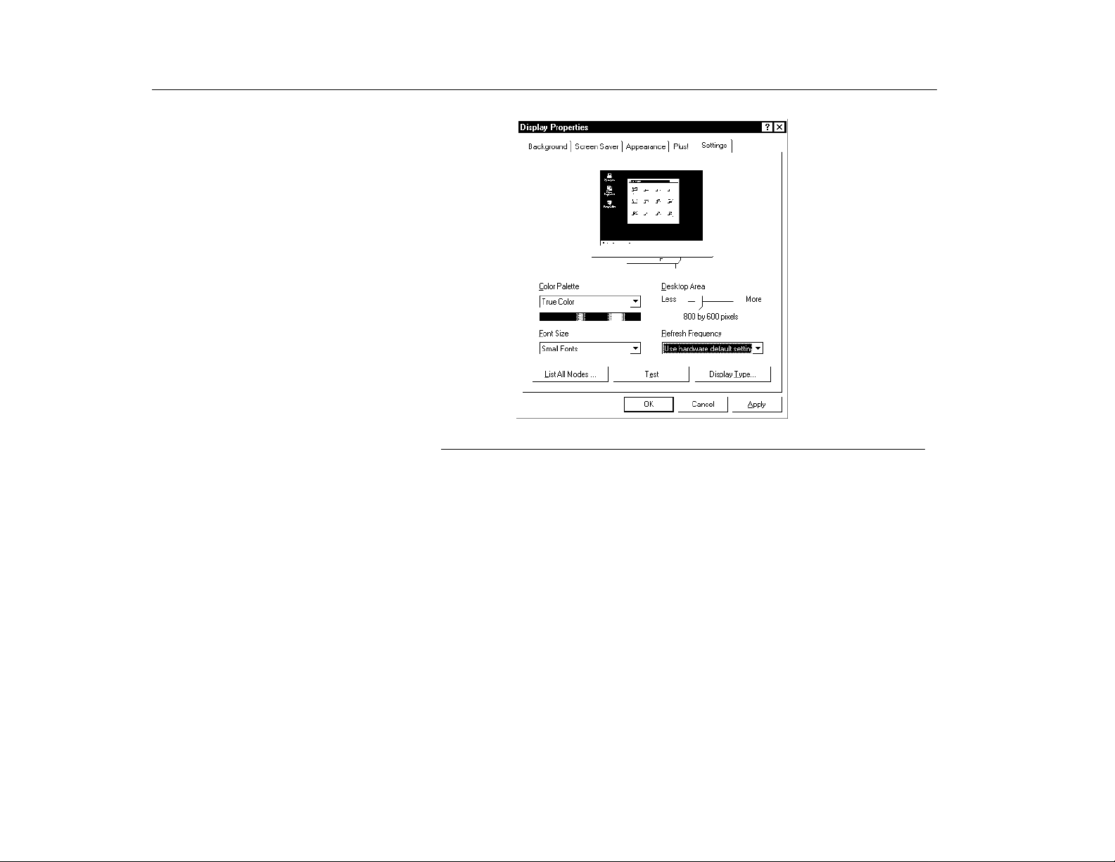
Video Features and Configuration
Resolution and Color Depth
5. Click the
Figure 19. Display properties in Windows NT 4.0
Settings
tab. The
6. To change the color depth, click the arrow next to
Settings
screen appears.
Color palette
color depth you want.
7. To change the resolution, click and drag the knob under the
you select the resolution you want.
8. Click the OK button.
9. Follow the prompts that appear on the screen.
and select the
Screen
area until
Changing the Video Driver
Windows 98:
56
It is possible that you may want to update your video driver or that your installed
video driver has become corrupt so that the display is unusable.
1. Click on the
2. Select
Settings
Display Properties
3. Click the
Advanced
Start
button. The
and click on
window appears.
button. The properties screen for your currently installed
Start Menu
Control Panel
will appear.
, double click on
Display
.
The
video driver appears.
4. Select the
Adapter
menu.
Page 57
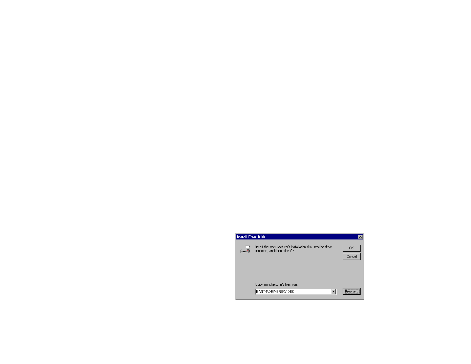
Video Features and Configuration
Resolution and Color Depth
Windows NT 4.0:
5. Click the
6. Click the
7. Select
Change
Next
Display a list of all the drivers in a specific location
button. The
button.
select the driver you want. Click the
8. Click the
floppy drive. Click the
Have disk
button. If the driver is on a floppy disk insert it into the
Browse
Update Device Driver Wizard
Next
button.
window appears.
,
so you can
button and locate the driver you want to install.
Click the OK button.
9. Select the new driver in the
10.Click the
Next
button to install the new driver and follow any directions on the
Select Device
screen and click the OK button.
screen to finish setting the display properties.
1. Log on to the computer as supervisor. The
Invalid Display Settings
window
may appear.
2. Click on the
3. Select
Settings
Display Properties
4. Select the
5. Click the
6. Click the
7. Click the
Settings
Display Type
Change
Have disk
Start
button and the
and click on
window appears.
menu.
button. The
button. If the driver is on a floppy disk insert it into the
button. The
Start Menu
Control Panel
Display Type
Change Display
appears.
, double click on
window appears.
window appears.
Display
.
floppy drive or if you want to use the original factory driver, insert the Restore
CD-ROM into the CD-ROM drive. Enter the path to the directory where the
drivers are located or click the
Browse
button and locate driver you want to
install. Click the OK button.
The
Figure 20. Enter location of the driver files
57
Page 58

Video Features and Configuration
Working with PC Cards
Working with PC Cards
A line similar to the following line appears under the
Mobility
8. Click OK. The
9. Click
10.Click OK. Remove the disk from the floppy drive. Close the open windows on
11.Click
12.Log on as supervisor. The
13.Click the OK button. Click the
By installing PC Cards, you can add functions to your notebook computer similar
to those found on add-in boards for desktop computers. Available PC Cards
include:
Your computer includes the following PC Card support:
.
Third-Party Drivers
Yes
. The driver is copied. A window appears informing you the driver has
been successfully copied.
the screen.
Yes
when prompted to restart the computer. As the computer restarts,
Windows NT Workstation Version 4.00
select
press [Enter].
Invalid Display Settings
and follow any directions on the screen to finish setting the display properties.
•
Input/output, such as modem, network, pager, video capture, and SCSI
cards.
•
Storage, such as hard drive and flash (SRAM) cards.
•
Combo cards, such as a combination modem and network card.
warning window appears.
Test
button at the
Display
as the Operating System and
Display Properties
option:
window will appear.
ATI 3D RAGE
window
58
•
Two PC-Card slots: You can install Type I, II, or III cards in the slots. Type
III cards are thicker than Types I and II. If you install a Type III card in the
bottom slot, you cannot install a card in the top slot.
•
CardBus hardware and software: CardBus enables the computer to use
32-bit PC Cards. Windows 98 supports 32-bit and 16-bit PC Cards. The
®
SystemSoft
systems that ship from the factory with Windows NT installed, also
supports both 16-bit and 32-bit cards.
•
Zoomed video: Both PC Card slots and the video chip on your computer
support zoomed video. When you install a zoom video PC Card in the
upper or lower slot, data can be transferred directly from the PC Card to
CardWizard™ for Windows NT program, provided with
Page 59
Video Features and Configuration
N
OTE
Working with PC Cards
video and audio systems without going through the microprocessor. V ideo
conferencing and real-time multimedia devices, such as video cameras,
are supported by zoomed video.
:
To use the CardBus and zoomed video technology with Windows NT, install the
CardBus and zoomed video drivers provided with your PC Card. If no drivers were
supplied with your card, contact the PC Card manufacturer. ATA (AT attachment)
and modem PC Cards do not require extra drivers.
Maintaining PC Cards
Using PC Cards
To maintain your PC Cards, follow these guidelines:
•
Keep cards away from excessive heat, direct sunlight, and liquids.
•
Do not drop, bend, flex, or crush cards when handling.
•
Keep dust, magnets, and static electricity away from PC Cards.
•
When a card is not in use, carry it in its protective carrying case.
•
Some PC Cards include cables that extend from the back of the cards. Be
careful not to bend or put excessive strain on these cables.
You can install PC Cards while the computer is on. To insert a PC Card into a slot:
1. Push the slot door in with the PC Card.
2. Align the card with a slot and insert the card into the slot until it locks in place
(Figure 21).
To remove a PC Card:
1. Push the eject button once to pop it outward.
2. Push the eject button again, then the card will be ejected.
59
Page 60
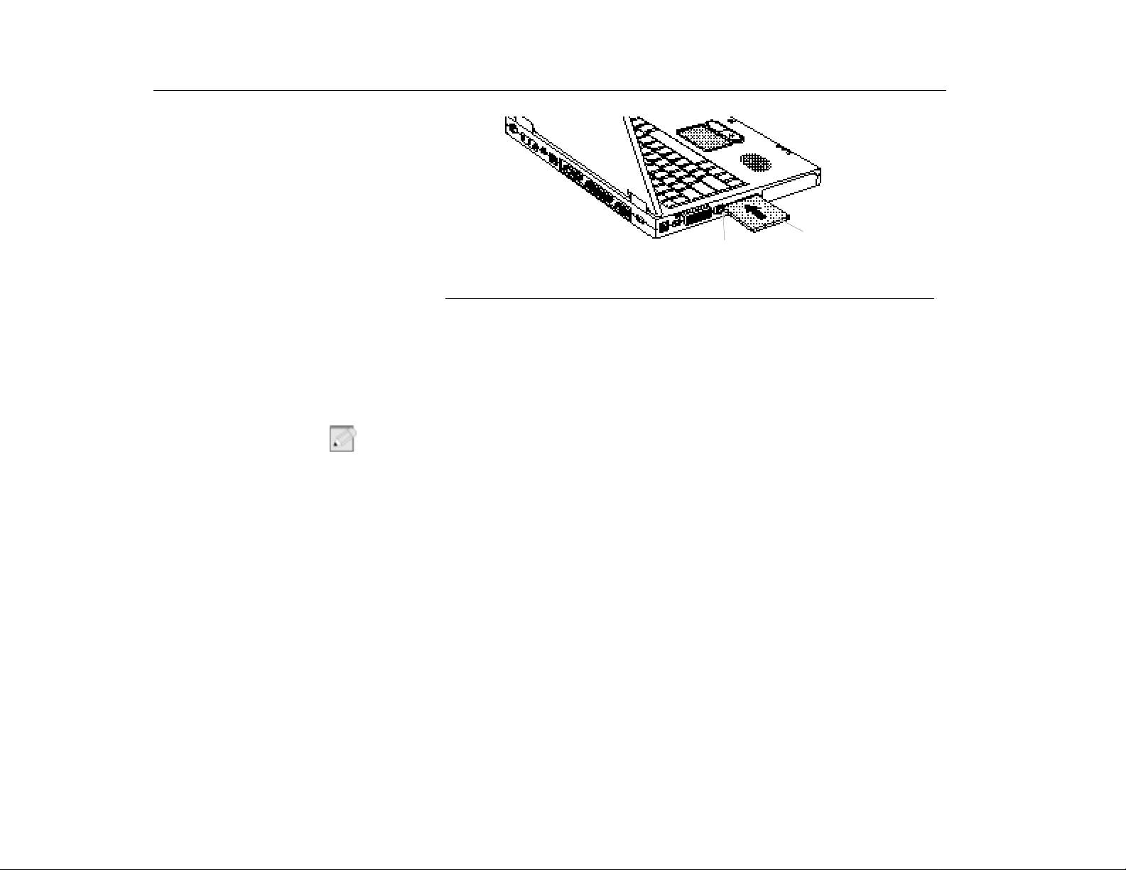
Video Features and Configuration
Working with PC Cards
Windows 98
Windows NT
N
OTE
Eject button
Figure 21. Inserting a PC Card
PC Card
Windows 98 automatically assigns computer resources (such as communication
ports and memory addresses) to a PC Card installed in your computer. For further
information on configuring a PC Card in Windows 98, see the index entry
in the Windows Help. Windows 98 also handles power management for PC
Cards.
Use the following procedures to remove PC Cards, or you may lose data that is
:
being stored to a card.
To remove a PC Card from your computer using Windows 98 Operating System:
1. Click the
PC Card
icon on the task bar.
2. Select the name of the card you want to remove, and then click the
button.
3. Push the card eject button on the side of the PC Card slot when prompted to
do so and then pull the card out of the PC Card slot.
Systemsoft Card Wizard is shipped with notebook computers that use Windows
NT as the Operating System. When you install a PC Card, CardWizard attempts
to configure it automatically. If Card Wizard successfully assigns system
resources to your card, the computer beeps twice.
PC card
Stop
60
Page 61
Video Features and Configuration
Working with PC Cards
If CardWizard cannot automatically configure your PC Card, the computer beeps
once and a message appears telling you that the card has not been configured.
Click the
why the card was not configured and fixes the problem or gives you information to
help fix the problem.
CardWizard works with the PowerProfiler program to manage PC Cards when the
computer enters or resumes from rest mode. CardWizard gives you instructions to
prevent loss of data before the computer enters rest mode or may stop the
computer from entering rest mode. ATA and modem cards can enter rest mode.
Follow these guidelines when using PC Cards with CardWizard:
Wizard
•
Some LAN (local-area network) cards can be inserted while the computer
is on but should be removed only when the system is turned off.
•
SCSI cards should be inserted at startup to enable Windows NT to find the
device attached to the SCSI card. SCSI cards can be removed when the
computer is turned off. If you restart your computer without the SCSI card
installed, a message may appear telling you that a service did not start.
You can ignore this message.
•
Modem and ATA cards can be inserted and removed while the computer is
on.
button on the CardWizard window. CardWizard then analyzes
AUTION
C
Before you remove a modem or ATA card from your computer, stop the card
:
through the CardWizard program or you may lose data.
To stop and remove a PC Card from your computer:
1. In the
2. Click
3. Push the card eject button on the side of the PC Card slot. Pull the card out of
4. For more information on using the CardWizard program, see the CardWizard
SystemSoft CardWizard
the name of the card you want to remove.
Stop
when the card is stopped. Click OK.
the slot compartment.
Help.
in the
Actions
screen, click with the right mouse button on
menu. A red stop sign appears on the main screen
61
Page 62

This page intentionally lef t blank.
62
Page 63

Using Options
Chapter 5 - Using Options
You can order the following options for your Notebook computer from your
authorized reseller:
The options that are available may change periodically. Contact micronpc.com for
updated information on current and new options.
AC Adapter
•
An extra AC adapter.
•
An auto adapter that enables you to charge the computer’s battery and
operate the computer in an automobile.
•
An extra battery pack.
•
32, 64 and 128 MB SDRAM memory modules that enable you to upgrade
your computer’s memory to a maximum of 192 MB.
•
A CD-ROM drive module.
•
A DVD-ROM drive module.
•
A Mini-PCI Software Modem module
or a LAN/Modem combined module (Type 3A).
•
A LS-120 Super Disk.
•
A Port Replicator.
•
A Secondary battery pack with internal charger.
AC Adapter
Auto Adapter
The optional AC adapter operates in the same way as the adapter that came with
your computer does. See ”Using the Battery” on page 41 for information about the
AC adapter.
The auto adapter enables you to power your computer and charge the computer
battery in an automobile, through the +12 volt cigarette lighter socket.
To use the adapter:
1. Plug the adapter cable into the AC adapter connector on the computer.
2. Connect the adapter to the cigarette lighter socket.
The light on the adapter is green when the adapter is working properly. The light
may be red for a few seconds when you first plug in the adapter or while you use
the adapter. This is normal. If the light remains red, check to make sure the
adapter is connected correctly.
63
Page 64
Using Options
N
OTE
Battery Pack
If the adapter is plugged in and the adapter light does not turn on:
•
Check the adapter connections.
•
If you are in an automobile, turn on the automobile’s ignition to supply
power to the adapter. In some vehicles, power to the cigarette lighter
socket is always on and you do not need to turn on the ignition.
•
If the previous procedures do not activate the adapter, you may need to
change the fuse in the adapter. To remove the fuse from the adapter,
unscrew the adapter cap with a pair of pliers and remove the cap. Replace
the fuse with an 8 amp fuse. In an automobile, you may need to replace the
fuse in the cigarette lighter socket.
When you connect the adapter to the cigarette lighter, the battery starts charging
immediately.
:
To prevent loss of data and possible damage to the computer, unplug the auto
adapter when starting and stopping the automobile engine.
Battery P a ck
Memory Modules
Before You Install Memory
64
AUTION
C
ARNING
W
N
OTE
You can order a smart lithium-ion battery pack for your computer. See ”Using the
Battery” on page 41 for information on the battery.
:
When changing the battery, power the system down and replace the battery. If
you try to replace the battery when the system is on, the system may become
unresponsive.
You can increase system memory by installing optional memory modules. You
can install 32, 64, or 128 MB modules.
:
To avoid possible system problems, use only approved memory modules in
your computer.
:
To prevent personal injury and damage to the equipment, follow the
precautions listed here before installing a memory module.
Page 65
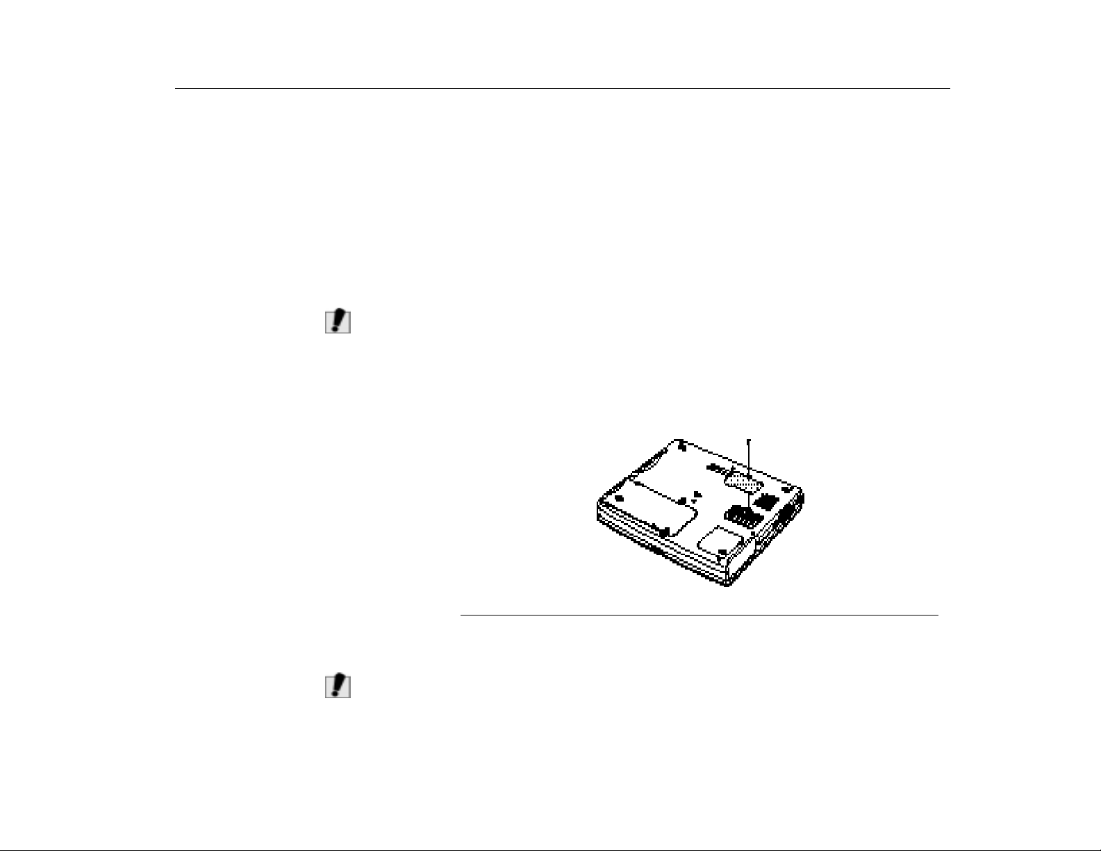
Using Options
Installing a Memory Module
C
AUTION
Take the following precautions when installing a memory module:
•
Before you remove the memory module compartment door, turn off the
computer, unplug the power cord, and remove the battery. Also, disconnect
any peripheral devices.
•
Before handling a memory module, discharge any static electricity by
touching a grounded surface or using a grounding wrist strap.
•
Do not insert objects with conductive material, such as metal screwdrivers
or graphite pencils, into the memory-module compartment.
•
Be careful in handling the metal plate of the memory door.
:
Handle a memory module carefully. Hold them only by the edges.
To install a memory module:
1. Turn the computer over so that the bottom faces up.
2. Using a screwdriver, remove the screw that holds the memory-module
compartment door in place (Figure 22).
Memory Modules
AUTION
C
Figure 22. Removing the Memory Module Compartment Door
3. Grasp the edge of the door and pull the door off the chassis.
4. Remove installed modules if necessary.
:
When removing modules, pull on the plastic portion of the connector slots
tabs only. Do not pull on the metal part of the tabs, or you may damage the
tabs.
65
Page 66
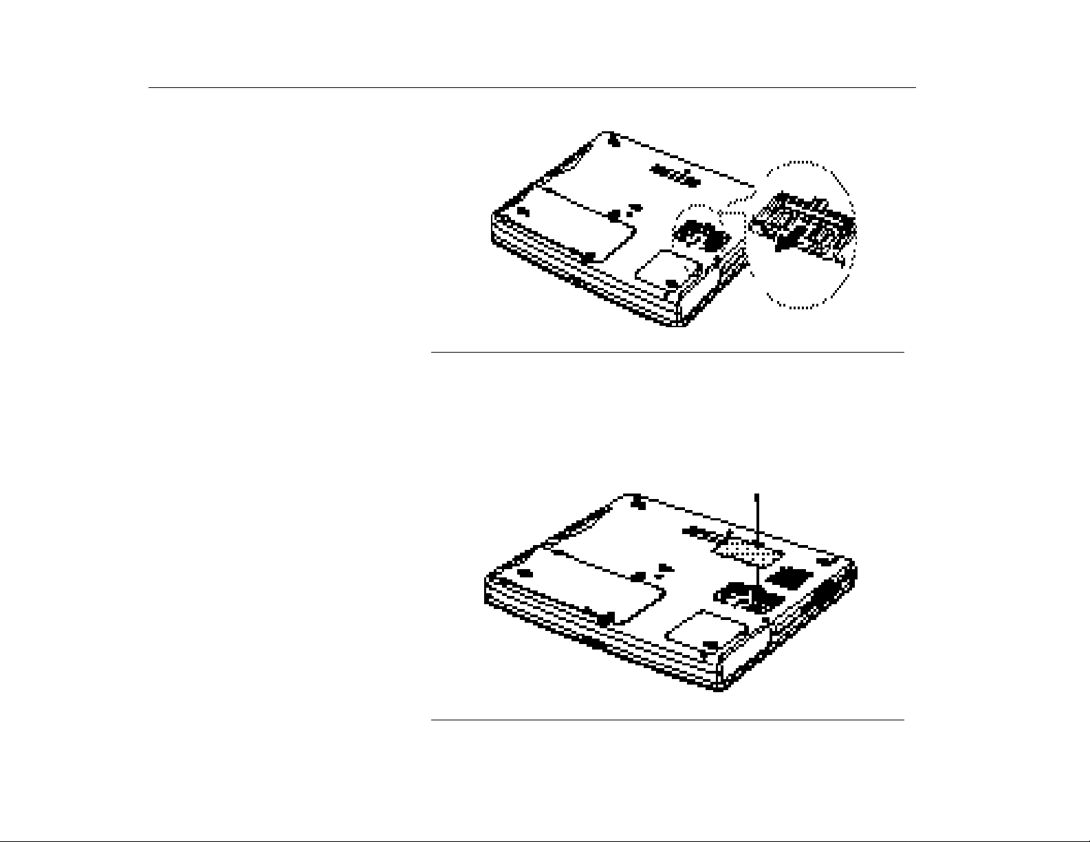
Using Options
Memory Modules
a. Pull the tabs on the connector slot outward slightly, until the edge of the
memory module pops up (Figure 23).
Tab
Tab
Figure 23. Removing a Memory Module
b. Hold the memory module by the edges and pull it forward out of the
compartment.
5. Align the connector on the memory module with the connector of the slot.
6. Push the memory module into the slot at a slight angle until the connectors are
fully engaged (Figure 24).
7. Push down on the edge of the memory module until the module snaps into
place.
66
Figure 24. Installing a Memory Module
Page 67

Using Options
CD-ROM Drive
8. Align the memory module compartment door with the compartment and push
the door down until it snaps into place.
9. Reinstall the screw you removed in step 2.
10.Turn the computer on and perform a complete POST to check the memory
integrity.
CD-ROM Drive
DVD-ROM Drive Module
Secondary Battery
If your system did not ship with a CD-ROM drive included, you can order a drive.
See ”Using the CD-ROM Drive” on page 37 for directions on installing the CDROM drive.
If your system did not ship with a DVD-ROM drive included, you can order a drive.
The DVD-ROM drive module can be inserted into your computer exactly as you
would insert a CD-ROM. See ”Using the CD-ROM Drive” on page 37 for directions
on installing and using the CD-ROM drive. There is MPEG-2 software included
with the drive that will enable you to play DVD movies from the DVD-ROM drive.
The secondary battery is available from micronpc.com.
The secondary battery has its own LED to show the battery charge remaining,
and it can be directly connected to an AC adapter to charge.
Charging time:
•
When the battery is connected to AC adapter directly: 3.2 ~ 3.8 hours.
•
When the battery is installed in the Flex-bay: 4 ~ 5 hours.
67
Page 68
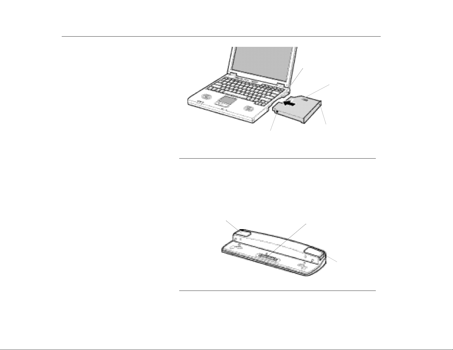
Using Options
Figure 25. Secondary Battery
Connect directly to
the AC adapter.
Port Replicator
Flex-Bay (see “Using the
Flex-Bay” on page 33)
Press the switch on
2nd battery to see
the battery charge
remaining
LED (Amber)
On- Charging
Off- Fully charged
Port Replicator
Features of the Port Replicator
68
Connecting the computer to peripheral devices on a regular basis has become
quick and easy with the 100-pin Port Replicator.
Eject button
connector
Eject button
Figure 26. Front view of the port replicator
Page 69
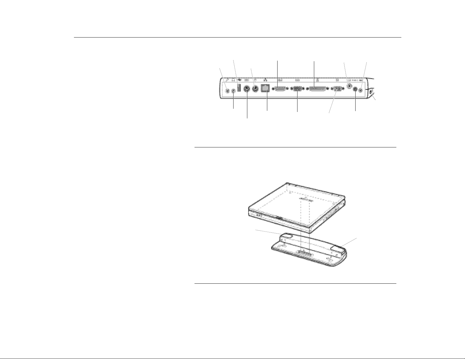
Using Options
Port Replicator
Installing a Port Replicator
USB device
Microphone
Headphone
Figure 27. Back view of the port replicator
PS/2 Mouse
PS/2 Keyboard
Joystick/MIDI
LAN Serial port
Printer
Monitor AC Adapter
TV-Out
1. Turn off your system and disconnect all the devices.
2. Adjust the connecting part of the system and the port replicator.
Line-In
Kensington
Lock
Eject button
Eject button
Figure 28. Connecting a Port Replicator
3. Push the system firmly to install a port replicator properly.
4. Connect an AC adapter to a power connector and cables from peripheral
devices.
69
Page 70
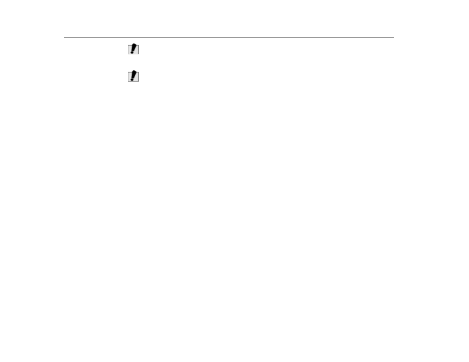
Using Options
AUTION
C
AUTION
C
Port Replicator
:
The system power must be turned off before connection or disconnection of
the port replicator from the system, or both devices could be damaged.
:
While the TV is ON, do not press [Fn+LCD/CRT] key. Pressing [Fn+LCD/
CRT] key may cause malfunction on TV-Out.
Removing a Port Replicator
1. Turn off the system.
2. Remove the AC adapter.
3. Push both eject buttons.
4. Remove the system.
70
Page 71

Drivers and System Resources
Chapter 6 - Drivers and System Resources
This section provides basic information about drivers and system IRQs.
Drivers
Drivers
IRQs
A driver is a program that enables the Operating System to work with a hardware
device. Your computer includes drivers for the audio, video, infrared, touchpad,
keyboard, CD-ROM drive, hard drive, floppy drive, and PC Card controller. When
you add a device to your computer, such as a printer, you install a driver for that
device. Different drivers are used by different Operating Systems.
Most of the devices in your computer are connected to your computer need their
own IRQ (interrupt request line). The IRQ is a hardware line that a device can use
to send signals to the microprocessor. When the device needs the
microprocessor’s service, the device sends an interrupt request signal to the
microprocessor.
The number of IRQs available for any computer is limited by industry standards.
Because it ships with numerous features, this computer uses most of the available
IRQs. If you add another device to your computer, you may need to disable an
existing device to free up an IRQ for the new device. IRQ resources are of
particular concern when the computer is attached to a docking device.
The default IRQ settings that are used by your computer are listed in Table 7.
TABLE 7. IRQs
IRQ Windows 98 Windows NT 4.0 Windows 2000
0 System timer System timer System timer
1 Keyboard Keyboard Keyboard
2 Internal Controller Internal Controller Internal Controller
3 IrDA Port COM 2, COM 4 IrDA Port
4 COM 1, COM 3 COM 1, COM 3 COM 1, COM 3
5 Audio/USB Audio/USB Audio/USB
6 Floppy controller Floppy controlle r Floppy controller
7 LPT1 (parallel port) LPT1 (parallel port) LPT1 (parallel port)
8 CMOS/Clock CMOS/Clock CMOS/Clock
9 ACPI bus SCI IRQ Reserved ACPI bus SCI IRQ
71
Page 72
Drivers and System Resources
Service Pack 6A for Windows NT 4.0
IRQ Windows 98 Windows NT 4.0 Windows 2000
10 Reserved Reserved Reserved
11 CardBus/Modem CardBus/Modem CardBus/Modem
12 Touchpad, PS/2 mouse Touchpad, PS/2 mouse Touchpad, PS/2 mouse
13 Numeric data processor Numeric data processor Numeric data processor
14 IDE 1 (hard drive) IDE 1 (hard drive) IDE 1 (hard drive)
15 IDE 2 (CD-ROM drive) IDE 2 (CD-ROM drive) IDE 2 (CD-ROM drive)
In Windows 98, you can configure a device so that the device is disabled when
you connect your computer to a docking station but enabled when the computer is
not connected to the docking station. With this configuration, an IRQ is available
for a peripheral device that you connect to the docking station. See your Windows
98 manual for more information.
Service Pack 6A for
Windows NT 4.0
72
ARNING
W
Microsoft Service Pack 6A (SP6A) is included with computers shipped from the
factory with Windows NT installed. Any time you change or add components to
your Windows NT system, you need to reinstall SP6A.
The version of SP6A on your computer’s hard drive includes the correct video
driver for your system. If possible, always install this version on your computer.
To install SP6A:
1. Run the executable file. This file is located on your computer’s hard drive at
C:\SP6A\i386\update.
2. Follow the instructions on the screen with these exceptions:
a. When you are prompted to overwrite the uninstall directory, click the
button.
b. When a prompt identifies your pcmcia.sys file as an OEM-installed file and
asks you to overwrite the version of the file on your system with the service
pack version, click the No button.
If you install any service packs on your computer in the future, make sure
:
that, when you are prompted, you do not overwrite the pcmcia.sys file, or
you may be unable to use the PC card slot.
Yes
Page 73

Drivers and System Resources
Installing the LAN Driver in Windows 98
Installing the LAN Driver in
Windows 98
Refer to the MRestore CD that came with your Transport LT for LAN installation
instructions specific to your Operating System.
73
Page 74

This page intentionally lef t blank.
74
Page 75

Using System Setup
Chapter 7 - Using System Setup
The System Setup program enables you to configure your computer hardware
and set security and power-savings options. The settings you choose are stored
in the battery-maintained CMOS memory that saves the information even when
the computer’s power is turned off. When your computer is turned back on, it is
configured with the values found in this memory.
Run System Setup if you get a message prompting you to run the program. You
may also want to run System Setup, particularly the first time you use your
computer, to set the time and date, use security or power-management features,
or alter the settings of other features.
Starting System Setup
Starting System Setup
N
OTE
Your computer’s version of System Setup may not include all the fields listed here
:
or may include additional fields. Field names and order of appearance can vary
according to the version of the BIOS (basic input/output system) on your
computer.
To start System Setup, turn on your computer. When prompted press [F2]. The
System Setup screen will appear.
The top of the System Setup screen has a menu bar with the selections listed in
Table 8.
TABLE 8. System Setup Menus
Menu Function
Main Changes the basic system configuration.
Advanced Configures advanced features on your
computer.
Security Enables se curity features, including
passwords and backup and virus-check
reminders.
Power Configures power-management features.
Boot Specifies the order of boot devices and
configures boot features.
Exit Specifies how to exit System Setup.
75
Page 76

Using System Setup
Starting System Setup
To open a menu, use the left or right arrow keys to select the menu name and
press [Enter].
Table 9 lists the keys you can use to navigate through System Setup.
TABLE 9. System Setup Navigation Keys
Navigation
Key
[F1] [Alt+H] D i sp lay s the Ge neral Help window.
[Esc] Exits the current menu. Moves location up a
[Left Arrow]
and [Right
Arrow] keys
[Up Arrow] and
[Down Arrow]
keys
[Tab] Moves the cursor forward through the cells for a
[Tab+Shift] Moves the cursor backward through th e cell s for
[Home] [PgUp] Moves the cursor to the field at the top of the
[End] [PgDn] Moves the cu rsor to the fie ld at the bottom of the
[F5] [-] Scrolls backwards through the options for the
[F6] [+] or
[F9] Loads factory installed Setup Default values.
[F10] Saves current settings and exits set up.
[Enter] Executes commands or opens a submenu.
Alternate
Key
Keypad
arrow keys
Keypad
arrow keys
[Space]
Function
level.
Select a different menu. Pressing [ESC] at the
Main menu brings you to the Exit menu.
Move the cursor up and down between fields.
highlighted field. Thi s works only in System Time
and System date.
a highlighted field. This works only in System
Time and System date.
window.
window.
highlighted field.
Scrolls forward through the options for the
highlighted field.
76
Page 77
Using System Setup
Main Menu
A pointer symbol appearing to the left of a field indicates that you can open a
submenu from this field. A submenu contains additional options for a field. To
open a submenu, highlight the field and press [Enter]. Use the same keys to enter
values and move from field to field within submenus as you use within menus.
When you highlight a field, information about the field appears on the right side of
the screen. System Setup also provides a General Help screen that can be
opened from any menu by pressing [F1] or [Alt+H]. The General Help screen lists
the navigation keys with their corresponding alternates and functions.
When a scroll bar appears to the right of a help window, more information is
availabl e than ca n be displa yed in th e window. Use the [ PgUp] and [PgDn] keys or
the [Up Arrow] and [Down Arrow] keys to scroll through the entire help document.
Press [Home] to display the first page, or press [End] to go to the last page. To
exit the help window, press [Enter] or [Esc].
If your computer will not boot after you have changed settings in System Setup
and exited the program, reboot and press [F2] to reenter System Setup. Once in
System Setup, you can try to change the values that caused your computer boot
to fail. If the problem persists, press [F9] to load the default values.
Main Menu
When you open System Setup, the Main menu appears. You can make changes
to your computer’s basic system configuration from this menu. The fields
displayed in this menu are described below.
TABLE 10. Main Menu
Feature Options Description
System Time: hh:mm:ss Sets your computer to the time that you specify,
usually the current time. Enter the hour, minute, and
second in the format
Use the [tab] key to move between the hour, minute,
and second cells. Use the hyphen key [-] or [Space]
bar to decrease or increase the numbers.
System Date: mm:dd:yyyy Sets your computer to the date that you specify,
usually the current date. Enter the month, day, and
year in the format
move between the month, day, and year cells. Use
the hyphen key [-] or [Space] bar to decrease or
increase the num be rs. Th is fi eld supports year d ate s
of 2000 and beyond.
hh:mm:ss.
mm:dd:yyyy
Use a 24-hour clock
. Use the [tab] key to
77
.
Page 78
Using System Setup
TABLE 10. (Continued) Main Menu
Feature Options Description
Legacy Diskette A:1.44 MB, 3 1/2
inch
Primary Master
and Secondary
Master:
Primary Master
Secondary Master
Specifie s a drive type for floppy drive A.
1/2 inch (
Y our com puter can sup port two IDE dri ves. The Main
menu contains two IDE adapter fields to configure
these drives.
installed in the computer.
the CD-ROM and DVD-ROM drives or Removable
drives.
To configure a replacement or upgrade hard drive,
move the cursor to select the
the System Setup Main menu, and then press the
[Enter] key. The submenu appears.
Normally, you can use the
field in the submenu to automatically set the values
for the other fields in the submenu. Manually set the
other fields in this su bmenu onl y if th e drive you ha ve
installed in your computer is not recognized by
System Setup.
default) floppy disk can be used.
Primary Maste r
Secondary Master
Auto
Main Menu
1.44 MB, 3
defines the hard drive
defines
Primary Maste r
option of the
field in
Type
78
N
AUTION
C
OTE
:
Set the Auto option of the Type field in the Secondary Master submenu to enable
the system to boot from Bootable CD-ROMS, you will also need to check the boot
device priority field and Bootable CD check field.
After you make your selections from this submenu, press the [Esc] key to exit
back to the Main menu.
:
Before attempting to configure a hard drive, make sure you have the
configuration information supplied by the manufacturer of the hard drive.
Incorrect drive settings can cause your computer to malfunction.
Page 79
Using System Setup
Main Menu
The Primary and Secondary Master fields calls up a submenu. The following fields
are found in the submenu:
TABLE 11. Primary and Secondary Master Fields Submenu
Feature Option Description
Type: Auto
User
None
Cylinders: Configures the number of cylinders for the hard drive.
Heads: Configures the number of read/write heads for the hard
Sectors: Configures the number of sectors per track for the hard
Maximum
Capacity:
Multi-Sector
Transfers:
LBA Mode
Control:
Disabled
2 Sectors
4 Sectors
8 Sectors
16 Sectors
Enabled
Disabled
Configures the hard drive type. Normally, select
this field to have your computer attempt to automatically
detect the drive type and set the values for the remaining
fields in this submenu manually, specify
enter the number of cylinders, heads, sectors per track,
and write pre-compensation for your drive. Refer to your
drive’s user documentation or look on the drive to obtain
this information. If no drive is installed or if you are
removing a drive and not replacing it, select
Refer to your drive’s user documentation or look on the
drive to obtain this information. Before you can make
changes to this field, the Type field must be set to
drive. Refer to your drive’s user documentation or look on
the drive to determine the correct value to enter for this
field. Before you can make changes to this field, the Type
field must be set to
drive. Refer to your drive’s user documentation or look on
the drive to determine the correct value to enter for this
field. Before you can make changes to this field, the Type
field must be set to
Shows the maximum capacity of the drive. This field is for
reference only.
Sets the number of sectors per block to the highest
number supported by the drive.
Enables or disables 28-bit addressing of the hard drive,
without regard for cylinders , he ad s, a nd s ec tors . En abl ing
this field may decrease the access speed of the hard
drive.
User
User
.
.
User
Auto
. Manually
None
.
User
at
.
79
Page 80
Using System Setup
TABLE 11. (Continued) Primary and Secondary Master Fields Submenu
Feature Option Description
32 Bit I/O: Enabled
Disabled
Transfer
Mode:
Smart
Monitoring:
Ultra DMA
Mode:
Standard
Fast PIO 1
Fast PIO 2
Fast PIO 3
Fast PIO 4
Enabled
Disabled
Mode 0
Mode 1
Mode 2
Disabled
Enables or disables 32-Bit I/O (input/output). When
Enabled
32-bit input and output. If the field is
your computer works with 16-bit input and output and has
lower performance.
Selects the method for trans ferring d ata betw een th e hard
drive and system memory. Refer to your drive’s user
documentation to specify the correct option for this field.
Default setting is
Monitoring function is used. This field is for reference only.
Enables the hard drive to use ultra DMA (direct memory
access) transfer mode to transfer data between the drive
and system memory.
, your hard drive can work with applications with
Disabled
Enabled
. Shows that the Smart
TABLE 12. (continued) Main Menu
Feature Option Description
System
Memory:
Extended
Memory:
BIOS Version /
Micom
Versi on:
CPU Type /
CPU Speed:
Displays the amount of conventional memory detected by
your computer during startup. This field is for reference
only.
Displays the amount of extended memory detected by
your computer during startup. This field is for reference
only.
Displays the BIOS version and Micom version.
Displays CPU type and speed.
Main Menu
(default),
80
Page 81
Using System Setup
Advanced Menu
Advanced Menu
Selecting
Advanced
from the menu bar displays the
Advanced
menu.
TABLE 13. Advanced Menu
Feature Option Description
Installed O/S: Select the Operating System installed on your system
which you will use most commonly. An incorrect setting
can cause unexpected system behavior.
PS/2 Mouse
Configuration:
Screen
Expansion:
TV Out Mode: PAL
Display
Configuration:
I/O Device
Configuration:
Local Bus IDE
adapter:
Large Disk
Access Mode:
Disabled
Single Mouse
Dual Mouse
Enabled
Disabled
NTSC
LCD
CRT
Both
(Table 14) Opens the
Enabled
Disabled
Dos
Other
Disabled
port from functioning.
PS/2 port or the touchpad, and external PS/2 port has
priority.
and PS/2 port.
Enables or disables the Screen Expansion mode. If you
set this field to
(DOS mode or 640x 480 Gr aphic mode) to use the fu ll siz e
of the LCD. If this field is
a 640x480 box in the LCD.
Select TV standard such as
Enables you to set the default display. Options are
CRT
only,
have both built-in and external displays used as the
default. If you select
attached you will not see a display until you attach the
external monitor. The default is
press [Enter] when this field is highlighted. If you attempt
to set two ports to the same settings, the fields will be
marked with asterisks.
Enables the integrated IDE local bus adapters. Options
are
Enables your computer’s Operating System to work with
drives larger than 540 MB. Choose
Microsoft Operating Sy stems. Cho ose
Operating Systems.
prevents both the touchpad and external PS/2
Single mouse
Dual Mouse
Both
and
CRT
to use an external monitor only, or
I/O Device Configuration
Enabled
(default) and
allows the use of both the touchpad
Enabled
. Choose
, the system expands VGA mode
Disabled
NTSC
LCD
to use the built-in display
CRT
and no external monitor is
Disabled
enables the external
VGA mode appears as
(default)
LCD
DOS
,
.
submenu if you
.
(default) for
Other
PAL
.
LCD
BOTH
for any other
,
to
81
Page 82
Using System Setup
The I/O Device Configuration submenu contains these fields:
TABLE 14. I/O Device Configuration Submenu
Feature Option Description
Serial port: En abl ed
Disabled
Infrared port: Enabled
Disabled
Parallel port: Enabled
Disabled
Floppy disk
controller:
Enabled
Disabled
Configures serial port. The options for this field are
Enabled
Enabled
IRQ4
the field is set to
System uses the default confi guratio n or the confi guratio n
you choose. If you select
use by another device.
Configures the infrared port. The options for this field are
Enabled
Enabled
Mode
IRQ4, 2F8 IRQ3
Mode FIR
channel to 3 or 1.When the
Enabled
default configuration or the configuration you choose. If
you select
another device.
Configures the parallel port. The options for this field are
Enabled
Enabled
Address
IRQ7
IRQ7
only, Bi-directional
ECP
setting enables you to set the DMA Channel to 1, 2, or 3.
When the
computer’s Operating System uses the default
configuration or the configura tion you cho ose. If you s elect
Disabled
Configures the floppy disk controller. The options for this
field are
Floppy disk controller
computer’s Operating System uses the default
configuration for the controller.
(default), and
you can set the
,
(default),
field. Settings for the
(default)
and
,
(extended capabilities port). Selecting the ECP
2F8 IRQ3, 3E8 IRQ4
Disabled
, and
you can set the
,
(fast infrared) enables you to set the DMA
, the computer’s Operating System uses the
Disabled
(default), and
you can set the
,
field. Settings for the
378 IRQ5, 278 IRQ7, 278 IRO5, 3RC
,
3RC IRQ5
Parallel port
you free up an IRQ for use by another device.
,
Enabled
Disabled
Enabled
Disabled
(default). If you set this field to
(default),
you free up an IRQ for use by
,
Disabled
. Settings for the
EPP
,
field is set to
(default), and
field is set to
. If you set this field to
Base I/O Address
, the computer’s Operating
Base I/O Address
Base I/O Address
3E8 IRQ4
Infrared port
. If you set this field to
Mode
field and the
Base I/O Address
(enhanced parallel port), and
Disabled
Advanced Menu
field to
2E8 IRQ3
or
,
you free up an IR Q for
,
field and the
2E8 IRQ3
or
,
field is set to
Mode
are
Enabled
When the
.
Enabled
3F8
. When
3F8
are
.
Base I/O
are
Output
, the
, the
3
78
82
Page 83
Using System Setup
Security Menu
Security Menu
Selecting
Security
from the menu bar displays the
Security
menu. Your
computer’s advanced security system allows you to set two different passwords to
prevent unauthorized access to system resources, data, and System Setup. From
the
Security
menu, you can enable a boot password, disk access, a system
backup reminder, and a virus check reminder.
Security fields marked with an asterisk (*) can only be changed if you start System
Setup with a system supervisor password or if no passwords are in effect. You
cannot access these fields with a user password.
TABLE 15. Security Menu
Feature Option Description
Supervisor
Password Is
and User
Password Is:
Set Supervisor
Password:*
Set User
Password:
Diskette
access:*
Supervisor
User
Displays whether user or supervisor password is in use.
Enables you to set the supervisor password to control
access to the System Setup utility. See ”Creating a
Password” on page 89 for instructions on setting a
password.
Enables you to set a user password to control access to
the system at boot. See ”Creating a Password” on page
89 for instructions on settin g a passwo r d.T he use r
password allows restricted access to the System Setup
Security menu; the user has access only to changing his
own password and to enable or disable
boot
. A supervisor password must be set before a user
password can be set
Enables you to restrict the use of floppy drives. When set
Supervisor
to
restricted to a user with the supervisor password. A
supervisor password must be enabled before the
Supervisor
users with either type of password have access to floppy
drives. If the field is set to
password is enabled, the user must enter the supervisor
password in order to boot from the floppy drive.
(default), the use of floppy drives is
option can take effect. When set to
Supervisor
Password on
User
and a user
,
83
Page 84
Using System Setup
TABLE 15. (Continued) Security Menu
Feature Option Description
Fixed disk boot
sector:*
Password on
boot: *
Normal
Write Protect
Enabled
Disabled
Enables you to write-protect the hard drive boot sector to
protect against viruses and alterations. Only a user with
the supervisor password can access this field.
Determines whether the c omputer prom pts for a pass word
when starting up. The option s are
A supervisor password mus t be set bef ore you can enable
this option. And the option should be enabled to use
[Fn+Keylock] function during the operation.
Enabled
Power Menu
Disabled
and
.
Power Menu
ARNING
W
The
Power
menu of System Setup allows you to enable and adjust your
computer’s sophisticated power-saving features. Enabling these features extends
the life of the battery.
If your computer shipped with Windows 98 or WIndows 2000 installed, the
:
Power Management works with the settings in the Power Management
option of Control Panel. But if your computer has Windows NT 4.0, the
Power Management works with the settings in System Setup.
84
Page 85
Using System Setup
TABLE 16. Power Menu
Feature Option Description
Power
Savings
Mode:
Standby
Timeout:
Auto
Suspend
Time out:
Maximum
Performance
Maximum
Power
Saving
Off
(Delay time of
1 to 16
minutes)
Enables and disables Maximum Performance mode. The
options are
Saving
this field to
and hard drive run at full speed, unless affected by other
power-savings settings. If you set this field to
Power Saving
at slow speed when there is no user input or device
activity. Choose
Disabled
Sets the period of computer inactivity (no user input or
device activity) that must pass before your computer
automatically goes into standby mode. In standby mode
some devices are turned off (including the LCD screen)
and the microprocessor slows down. You can disable this
option by selecting
Timeout
Sets the period of computer inactivity from standby that
must pass before your computer automatically goes into
rest mode. When the rest timeout expired, your computer
goes to the rest mode according to Suspend Mode.
Maximum Performance, Maximum Power
(default)
Maximum Performance
to turn off the Power management function.
delay time of 1 to 16 minutes.
Power Menu
Customized
,
the microprocessor and th e hard drive ru n
,
Customized
Off
or you can specify a
,
Disabled
and
,
to alter these settings and
. If you set
the micropr ocessor
Maximum
Standby
85
Page 86

Using System Setup
TABLE 16. (Continued) Power Menu
Feature Option Description
Suspend
Mode:
Hard Disk
Timeout:
Resume On
Modem Ring:
Resume On
Time:
Save To RAM
Save To Disk
Specifies the type of rest mode your computer enters:
Save to RAM
•
microprocessor and all devices except system
memory and controller, and video memory and
controller.
Save T o Disk
•
capabilities by essentially turning off your
computer. In the save to disk mode, all system
logic (except for your computer wakeup circuitry
and battery charger) is turned off. During save to
disk mode, the system and video mem ory are
saved to the hard drive and are restored when
your computer resumes from rest.
When the computer enters save to disk mode, it
•
will not resume normal operation at a specified
time no matter how the
set.
Sets the amount of time the hard disk needs to be inactive
before it is turned off.
Enables the computer to resume operation from rest
mode in the event of modem communication. The
computer will resume only if the
set to
Save to RAM
setting is
be plugged into the computer.
Enables the computer to resume operation from rest
mode at a sch edu led time. The compu ter w ill resume only
if the
Save To Disk
Resume Time
adapter should be plugged in to work this feature.
Off
Suspend Mode
Power Menu
Saves power by turning off the
:
Provides the greatest po wer-saving
:
Resume On Time
Suspend Mode
not
,
Save To Disk
To enable this feature, AC adapter should
.
field is set to
If you set this field to On, you must set the
.
field as well. The default setting is
The default
.
Save to RAM
field is
field is
not
,
Off
AC
.
86
Page 87
Using System Setup
TABLE 16. (Continued) Power Menu
Feature Option Description
Resume
Time:
Speedstep
Mode:
hh:mm:ss Specifies the time for your computer to automatically
resume from rest mode. Enter two-digit numbers to
indicate the hour, minutes, and seconds in the format
hh:mm:ss
between the hour, minute, and second cells. Use the
hyphen key [-] or [Space] bar to decrease or increase the
numbers.
You must set this option if you enable
Selects the mode of Intel Speedstep support to install in
the user BIOS at runtime. If your CPU does not support
Intel Speedstep, this field should be set to
. Use a 24-hour clock. Use the tab key to move
Boot Menu
Resume On Time
Disabled
.
.
Boot Menu
The Boot menu enables you to select a boot device and set boot options.
TABLE 17. Boot Menu
Feature Option Description
Screen Logo
Display:
Summary
screen:
Boot Device
Priority:
Enabled
Disabled
Enabled
Disabled
Default:
1.Diskette
Drive,
2.Removable
Devices,
3.Hard Drive,
4.DVD/CDROM
Enables or Disables the display of the boot time logo. If
you select
displayed during boot.
Displays the system configuration when the computer
starts. The options are
Enables you to select the order in which the computer
attempts to boot from dif ferent device s. The field has thre e
options:
Drive
To choose a device as the first, second, or third boot
device:
1.
2.
3.
4.
5.
Disabled
Diskette Drive
DVD-CD ROM
and
,
Press [Enter] at the
Press [Enter] at the plus(+) symbol to display sub
menu.
Highlight the option with the [Up Arrow] or [Down
Arrow] key.
Press the [Space] bar until the option moves up or
down in the list of options
Press [Esc] to return to the Boot menu.
, the diagnostic POST screen is
Enabled
Removable Devices, Hard
,
.
Boot Device Priority
and
Disabled
(default).
field.
87
Page 88
Using System Setup
N
OTE
:
If you want to start the system using a bootable CD, change the ATAPI CD-ROM
Drive to be the first priority and make sure the Auto is set in the Type field of the
Secondary Master Submenu at Main page, and also make sure that Enabled is
set in the Bootable CD check field at Boot page.
Exit Menu
Exit Menu
N
OTE
Exit
Select
:
Pressing [Esc] does not exit this menu. You must select one of the options from
or press [Esc] from the menu bar to display the
Exit
menu.
this menu or a menu bar item to exit this menu.
TABLE 18. Exit Menu
Feature Option Description
Exit Saving
Changes:
Exit
Discarding
Changes:
Load Setup
Defaults:
Smart Battery
Calibration:
Yes
No
Yes
No
Yes
No
Enables you to exit System Setup and saves your
changes. When you sele ct this item and press [Enter], a
message appears asking you if you want to save your
changes and exit System Setup. Choose
[Enter] to save your changes and exit. Choose No and
press [Enter] to remain in System Setup.
Enables you to exit System Setup without saving your
changes. When you sele ct this item and press [Enter] a
message appears a sking you i f yo u want to sa ve ch anges
before exiting. Choose No and press [Enter] to exit
without saving changes. Choose
save changes and exit.
Loads the default values fo r all System Setup parame ters.
When you select this opt ion and pr ess [Ente r], a mess age
appears asking if you want to load the default
configuration. Choose
default settings and remain in System Setup. Choose No
and press [Enter] to retain your changes and remain in
System Setup.
Enables you to discharge the system battery completely
for a more accurate battery level detection. This option
only works with the smart battery if the AC Adapter is not
plugged in.
Yes
Yes
and press [Enter] to load
Yes
and press [Enter] to
and press
88
Page 89

Using System Security
Chapter 8 - Using System Security
This section describes the security options provided with your computer.
System Passwords
System Passwords
Creating a Password
The computer provides two levels of password security: administrative-level
(supervisor) and user-level (user). Either password prevents unauthorized access
to the computer. The supervisor password enables full access to all System Setup
fields. The user password enables full access to only the
Password on boot
fields. (See ”Security Menu” on page 83 for a complete list of System Setup
security fields.)
If multiple users have access to the computer (such as in a network environment),
a supervisor password can prevent unauthorized access to certain security
options.
Choose the type of password security that is appropriate for your work. If you want
to set a user password, you must set a supervisor password first.
To create a password:
1. At startup, press [F2] to open
2. Use the [Right Arrow] key to select the
3. Use the [Down Arrow] key to select
Password
4. Type a password of up to seven characters. You can enter letters or numbers,
but you cannot use the function keys, such as [Shift]. Your computer does not
distinguish between capitalized and lowercase letters in your password. As
you type the password, the cursor moves but your password does not appear
on the screen.
5. Press [Enter] after you have typed your password. The computer prompts you
to reenter your password for verification.
6. Type your password again and press [Enter]. A message appears telling you
that the changes have been saved. Press [Enter] again to return to the
Security
7. Press [Esc] to go to the
8. Select
the computer.
menu.
Exit Saving Changes
security fields and read access to all other System Setup
.
Press [Enter]. The
Exit
System Setup
Set Supervisor Password
Set Password
menu.
, press [Enter], and press [Enter] again to restart
.
Security
dialog box will appear.
Set User Password
menu.
Set User
or
and
89
Page 90

Using System Security
System Passwords
Deleting a Password
Requiring a Boot Password
To delete the password:
1. At startup, press [F2] to open
2. When prompted type your password and press [Enter].
3. Use the [Right Arrow] key to select the
4. Use the [Down Arrow] key to select
Password
5. Press [Enter]. The computer prompts you to enter the current password.
6. Press [Enter]. The computer prompts you to enter a password. Do not type
anything.
7. Press [Enter]. The computer prompts you to reenter the password. Do not type
anything.
8. Press [Enter]. A message appears telling you that the changes have been
saved. Press [Enter] again to return to the
9. Press [Esc] to go to the
10.Select
the computer.
After you create a supervisor or user password, you can enable the computer to
prompt for a password each time it starts.
To enable the prompt, select the option
System Setup. For more information about the
“Security Menu” on page 83.
.
Exit Saving Changes
System Setup
Set Supervisor Password
Exit
menu.
, press [Enter], and press [Enter] again to restart
Enabled
.
Security
menu.
Security
Password on boot
menu.
Password on boot
in the
or
field, see
Set User
field in
Locking the Hard Drive Boot
Sector
Locking the Floppy Drive
90
If you have a supervisor password, you can lock the hard drive boot sector to
protect against viruses or alterations.
To lock the hard drive boot sector, select the option
disk boot sector
disk boot sector
If you have a supervisor password, you can lock the floppy drive so that a user
with only a user password cannot load personal software, which may introduce a
virus into the computer.
field in System Setup. For more information about the
field, see “Security Menu” on page 83.
Write protect
in the
Fixed
Fixed
Page 91

Using System Security
System Passwords
Locking the Keyboard
To enable the floppy lock, select the option
System Setup. For more information about the
Menu” on page 83.
The keyboard lock enables you to protect your system when you walk away from
it for a time. To use the keyboard lock, you must first enable a password through
System Setup. (See ”Creating a Password” on page 89 for instructions. To lock
your keyboard, press [Fn+F7]. To unlock your keyboard, type your password and
press [Enter].
Supervisor
Lock Floppy
in the
Lock Floppy
field, see “Security
field in
91
Page 92

This page intentionally lef t blank.
92
Page 93

Using Power Management Options
Chapter 9 - Using Power Management Options
Your computer includes power-management options that can help the battery
charge last longer and extend the life of the battery, LCD panel, and other
components. Power-management options slow down or shut off system
components when the components are not being used.
Power management may slow down system performance. Your computer runs
fastest with the power cord attached, and when power management is disabled.
In Windows 98 and WIndows 2000 Power management works according to the
settings in the Power Management option on the Control Panel with the exception
of rest mode.
If your computer shipped from the factory with Windows NT installed,
PowerProfiler software was included to support power management.
Maximum Power Saving Mode
Maximum Power Saving
Mode
Standby Mode
N
OTE
For maximum power saving mode, the microprocessor may run at slow speed to
conserve power. To enable this mode, set the
Enabled
The
period that the computer can remain idle (no user input or disk activity) before the
computer enters standby mode. You can disable this option by selecting
you can specify a
In standby mode, the system and video memory and the video controller slow
down. The LCD backlight, hard drive, floppy drive, PC Card controller, and some
other devices turn off to save energy. DPMS (display power-management
signaling), a form of monitor power management, to an external monitor is
invoked.
To resume from standby, press the Power button or touch the touchpad. Do not
press any keys on your keyboard. Windows 98 does not have a standby mode.
In Windows 98 and WIndows 2000, the standby mode works the same as rest
:
mode in system setup. Windows 98/2000 has a standby mode that operates
separately from the standby mode in system setup.
.
Standby Timeout
Standby Timeout
field in
System Setup
delay time of 1 to 16 minutes.
Idle Mode
enables you to specify the time
field in
System Set up
Off
to
, or
93
Page 94

Using Power Management Options
Suspend Mode
If you enable both standby and rest modes, your computer enters standby when
the delay time you chose for standby has elapsed, and then enters rest mode
when the delay time you chose for rest mode has elapsed.
Suspend Mode
N
OTE
The
Auto Suspend Timeout
time period the computer can remain idle (no user input or device activity) before
the comput er e nters
or you can specify an
The
Suspend Mode
computer enters:
•
Save to RAM:
and DMA clocks, video, and all controllable peripheral devices. The
computer still uses some power while in this mode. If you leave your
computer in
attached, the computer’s battery will discharge.
•
Save To Disk:
by essentially turning off your computer. In this mode, all system logic
(except for your computer wakeup circuitry and battery charger) is turned
off. During save to disk mode, the DRAM and video memory are saved to
the hard drive and are restored when your computer resumes operation.
You can press [Fn+F4] to manually place your computer into Suspend mode.
When you use the [Fn+F4] key combination, your computer may postpone
:
Suspend
Auto Suspend Timeout
field in
This mode saves power by turning off the microprocessor
Save to RAM
This mode provides the greatest power-saving capabilities
field in System Setup enables you to specify the
mode. You can disable this option by selecting
delay time from 5 to 60 minutes.
System Setup
for several days without the power cord
defines what type of rest mode your
entering Suspend mode during a critical operation, such as reading from or writing
to the hard drive.
To resume to full-power mode, press the power button.
Off
,
Suspend Mode Precautions
94
Once all devices return to full-power mode, all active software applications and
system states are restored to exactly how they were before your computer
entered rest mode.
When your computer enters or resumes from save to disk mode, screens appear
indicating system status. These status screens do not appear when the computer
enters or resumes from power on Suspend Mode.
Observe the following precautions when using Suspend mode:
Page 95
Using Power Management Options
AUTION
C
Using PowerProfiler
•
Save all open files before you press [Fn+F4] to manually place your
computer into Suspend mode.
•
If you purchased a new hard drive, make sure that you create a save to
disk partition equal to the amount of system memory plus the amount of
video memory plus 2 MB, before you enable save to disk mode. See
”Creating a Save-To-Disk Partition” on page 97 for more information.
•
Do not try to resume to full-power mode using battery power if the battery
charge is low. If the battery charge is too low, the system may not be able
to resume fully. Plug in the power cord if your computer cannot resume
normal operation because of a low battery charge.
:
When your computer is in Save to RAM or Save to Disk mode, do not
connect or remove any devices (including PC Cards or memory modules)
because you may damage the computer or Resume To Full Power may fail.
If a floppy disk is in the floppy drive, do not remove it or switch it with
another disk. However, you can plug in the AC adapter if the Resume To Full
Power fails because of a low battery charge. When the computer is in Save
To Disk mode, you can remove and replace the battery.
Using PowerProfiler
PowerProfiler enables you to set power-management options for computers
shipped with Windows NT installed. To open the PowerProfiler window, doubleclick the battery icon on the right corner of the Windows task bar or click on the
PowerProfiler icon in the Program bar. If you click the icon with the right mouse
button, a menu appears with an option to put the computer in Suspend mode.
Click the
drive. You can also set power management to be enabled:
or
options, and the Battery screen enables options to conserve battery life.
Keep the following in mind when using PowerProfiler:
Standard
Never
. The
•
If you disable power management in PowerProfiler, the setting overrides
any power-management settings in System Setup.
•
If you enable LCD and hard drive timeouts in PowerProfiler and the
standby timeout in System Setup, the LCD and hard drive turn off when the
shortest timeout period in either program passes.
tab in PowerProfiler to set timeouts for the LCD and the hard
Advanced
Always
screen in PowerProfiler enables resume from rest
Battery Only
,
95
,
Page 96
Using Power Management Options
Using PowerProfiler
N
OTE
•
If you disable the
PowerProfiler is also automatically disabled. An easy way to work with
these two fields is to set the resume time to 0 in System Setup and set the
actual resume time that you desire in PowerProfiler.
PowerProfiler maintains the accuracy of the system clock when the computer
:
Resume on Time
field in System Setup, the same field in
resumes from rest mode. If PowerProfiler is closed or removed from your hard
drive, your system clock may not be accurate when your computer resumes from
rest mode.
For more information on PowerProfiler, see the Help option in the PowerProfiler
software.
96
Page 97

Creating a Save-To-Disk Partition
Chapter 10 - Creating a Save-To-Disk Partition
The hard drive shipped in your computer has a save-to-disk partition in which data
from system and video memory is stored during save-to-disk mode. The partition
is the maximum size needed for your computer and supports system memory of
256 MB. You can add memory modules to your computer without changing the
size of the partition.
Using PowerProfiler
N
N
N
OTE
OTE
OTE
You do not need a Save-to-disk partition if you are running Windows 2000.
:
Windows 2000 handles Save-to-disk as hibernation. See the Windows 2000
manual for more information.
If you add a new hard drive to your computer, you need to create a save-to-disk
partition on the new hard drive.
If you do not intend to use save-to-disk mode, you do not need to create a save-
:
to-disk partition.
You can use the Phoenix PHDISK utility, provided on the MRestore CD-ROM disk
to create the save-to-disk partition.
If you want to put programs or files from your current hard drive onto the new hard
drive, back up data files on your old hard drive before creating a save-to-disk
partition on the new drive.
If you do not intend to use the save-to-disk mode, you can delete the save-to-disk
:
partition on a hard drive using PHDISK /delete. Then you can repartition and
reformat the save-to-disk partition for some other application. Back up your hard
drive before deleting the partition if you feel unsure about how to do this.
Before you use PHDISK to create a save-to-disk partition, do the following:
•
Under the Boot menu in System Setup
device (see “Using System Setup” on page 75 for information on setting
options).
•
Create a PHDISK disk.
To create a suspend partition:
,
set
Diskette Drive
as the first boot
97
Page 98

Creating a Save-To-Disk Partition
Using PowerProfiler
1. Turn off the computer, remove your old hard drive, and insert the new one into
your computer. (See ”Using the Hard Drive” on page 39 for instructions.)
2. Insert the PHDISK disk into the floppy drive and start your computer.
3. At the A: prompt, type phdisk /create 206784 /partition and press [Enter].
PHDISK automatically creates a save-to-disk partition of the maximum size for
your computer. When the save-to-disk partition has been created, the
message “Save-to-disk partition created successfully” appears.
4. Remove the PHDISK floppy disk from the floppy drive.
5. Install your computer’s Operating System and your original applications and
drivers.
6. Reinstall any program and data files that you backed up.
98
Page 99

Software Utilities
Chapter 11 - Software Utilities
MRestore CD-ROM
MRestore CD-ROM
MCRC (Micron Customer
Resource Center)
OTE
N
Included with your notebook computer is a CD-ROM titled MRestore. This CD is
only functional on Micron systems with an approved Micron BIOS.
Included on this CD-ROM are the following:
•
The MCRC (Micron Customer Resource Center)
•
Drivers (with instructi ons )
•
A bootable option to access basic DOS functions, such as disk, format, etc.
•
Drive Image / PartitionMagic / Drive Copy by PowerQuest
•
Drive Image manual/user’s guide (more comprehensive than space allows
within this guide). These may or may not reflect the actual package that
you have; other applications may or may not be referenced.
Use this CD to install drivers one at a time. It is a program that can only be used
from within Windows. This CD is needed to load any drivers that are not shipped
installed on the notebook as a default (such as DVD).
To use the MCRC, boot your system to its current operation system (such as
Windows 95/98), insert the MCRC CD and follow all instructions.
All drivers are pre-installed and tested by Micron. You will not have to run this CD
:
unless you are experiencing problems with your system or if you have recently
reinstalled the operation system.
PartitionMagic
Drive Image 3.0
Partition magic software is provided so you will have a method of storing an image
if no other means of storage are available. PartitionMagic can only be run from
DOS level. The object of this software is to create partitions and move them to an
appropriate size for your needs. It also converts them with different FAT tables.
This software becomes very useful when there is no location for your storage.
This is a brief overview of what is contained in the PDF located in
the:\pqtools\userinfo directory on the CD.
Drive Image is for PC users who want a fast, complete solution for system
backups and recovery. With Drive Image you can easily create and store a
99
Page 100
Software Utilities
N
OTE
Drive Image 3.0
compressible image of the entire hard drive or individual partition on a Jaz, Zip,
secondary hard drive, or other removable media device. The image can then be
restored from the source and used for complete Operating System application
and data recovery.
:
Currently, Drive Image does not support creating image files directly on CD-ROM
or tape drives. You must first save image files to a supported source (hard drive,
Zip drive, etc.), then copy them to CD-ROM or tape. Drive Image can, however,
directly restore image files from CD-ROM.
Furthermore, image files can only be saved to devices that have a valid drive
letter. While Drive Image includes some device drivers (such as Zip), the user is
primarily responsible for loading the necessary drivers for their data storage
devices so that DOS can correctly assign drive letters (such as USB Zip or 2 GB
JAZ).
Drive Image also includes other useful features such as the ability to resize
partitions, disk to disk copying for upgrading to a larger hard drive, and file
systems error and bad sector checking to prevent copying problems.
Drive Image supports the file systems of all versions of Windows 95/98, Windows
NT, Windows 3.x, DOS. And OS/2 including FAT32, FAT32X, NTFS, and HPFS
partition types. Because Drive Image understands the internal structure of these
file systems, partition resizing and fast SmartSector copying can occur.
100
Drive Image provides limited support for NetWare, Linux, UNIX and other partition
types. However, Drive Image copies such partitions sector by sector—and does
not resize them on the destination drive—making the image file creation and
restoration process for these file systems more time consuming. Additionally,
internal disk location references are not modified on the destination drive. This
may make these partitions unbootable or otherwise inaccessible.
Drive Image is a DOS-based program that can be run from the hard drive in DOS
or MS-DOS mode or from a CD after booting DOS. Because multi-tasking
Operating Systems like Windows 95/98 and Windows NT operate with open files
on the hard drive, it is necessary to run Drive Image from DOS so that image files
are an exact copy of your hard drive. By running DOS, the hard drive is
completely inactive with no open files.
 Loading...