

Page 1

AU8000
SPRAYER
Operator's Handbook
and
Parts Catalogue
Micron Sprayers Limited
Bromyard Industrial Estate
Bromyard
Herefordshire HR7 4HS
United Kingdom
Tel: (01885) 482397
+44 1885 482397
Fax: (01885) 483043
+44 1885 483043
E-mail: micron@micron.co.uk
Web site: www.micron.co.uk 07/03
Iss 12
Page 2

TABLE OF CONTENTS
1. INTRODUCTION ............................................................................................. 1
2. SPECIFICATION ............................................................................................. 1
3. ASSEMBLY ..................................................................................................... 2
4. OPERATION ................................................................................................... 3
4.1 Operation of Standard Sprayer ............................................................. 3
4.2 Operation of Sprayer with Chemical Pump ........................................... 5
4.3 Operation of Sprayer with Filling Pump................................................. 6
5. HEALTH AND SAFETY................................................................................... 6
6. CALIBRATION................................................................................................. 8
6.1 Output Rate of Chemical....................................................................... 8
6.2 Adjustment of Droplet Size.................................................................. 12
7. MAINTENANCE ............................................................................................ 13
7.1 Knapsack Mistblower – Routine Maintenance .................................... 14
7.2 Possible Engine Faults and Remedies................................................ 14
7.3 Maintenance of Sprayhead ................................................................. 16
8. PARTS LISTS................................................................................................ 18
8.1 AU8000 Sprayhead............................................................................. 18
8.2 AU8000 Atomiser................................................................................ 20
9. CONVERSION FACTORS ............................................................................ 22
Page 3

1. INTRODUCTION
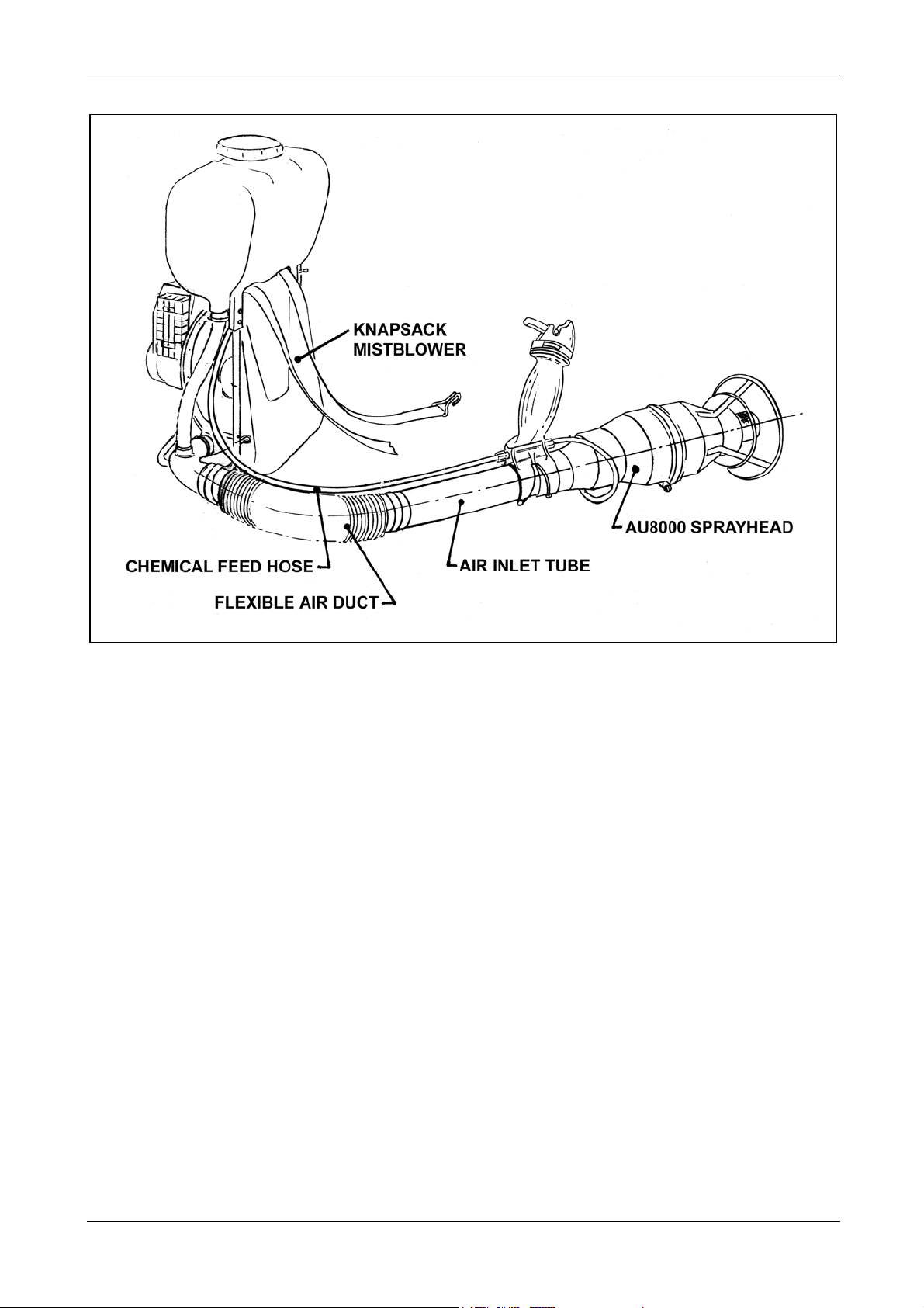
The AU8000 Sprayer consists of a Micronair AU8000 sprayhead mounted on a knapsack
mistblower.
The sprayhead provides a narrow, easily controlled spectrum of spray droplets to ensure
an even distribution of product with a minimum of wastage. Air from the mistblower rotates
the atomiser and is then directed into the airstream which carries the spray safely away
from the operator and ensures maximum swath width and penetration of foliage.
The AU8000 sprayer is intended for use in agriculture, public health spraying, migratory
pest control (locust, armyworm etc.) and in any other application where a safe, effective,
portable sprayer is required. It can be used with conventional water-based chemicals
(both solutions and solids in suspension) and with specialised ULV formulations. The unit
is supplied with easily interchangeable restrictors for quick and easy calibration of output
rate for all chemicals and application techniques.
Regardless of chemical type or application rate, the AU8000 sprayhead ensures optimum
coverage of the target with a minimum wastage of chemical due to incorrectly sized
droplets or run-off.
The AU8000 sprayhead is also available separately as a conversion kit for use with an
existing mistblower. For satisfactory operation, the air output from the mistblower must be
as shown in the specification below.
2. SPECIFICATION
AU8000 Sprayhead
Length: 30 cm
Diameter: 15 cm
Weight: 1.5 Kg
Air inlet tube dia: 65 mm
Chemical flow rate: 0.02 – 1.20 litres/min
Spray droplet size: Adjustable 40 – 200 microns VMD subject to formulation used
Tank and Blower
Chemical tank capacity: 17 litres max
Weight (empty): 10.7 Kg
Engine: 77 cc 5 HP (3.6 KW) 2-stroke
Fuel tank capacity: 2 litres
Fuel consumption: 2 litres/hour approx
Blower output: 20 m3/min
Air velocity: 125 m/sec at outlet
MICRONAIR AU8000 SPRAYER
Page 4

2
3. ASSEMBLY
These instructions apply both to AU8000 sprayheads supplied as part of a complete
sprayer and to sprayheads supplied as conversion kits. The steps with numbers in square
brackets [ ] refer to conversion kits ONLY and should be disregarded when assembling a
sprayer supplied complete. There may be some minor differences when installing
conversion kits on some models of sprayer. Parts are identified by their reference number
in Fig. 5.
[1.] Ensure that the mistblower is empty, clean and in good running order.
[2.] Disconnect the chemical feed hose from any existing on/off valve or flow regulator.
Leave the feed hose connected to the chemical tank.
[3.] Remove the original spray nozzle and outlet, leaving only the flexible air duct
attached to the blower.
4. Insert one end of the rigid air tube (19) into the inlet of the sprayhead so that 40 mm
of tube is inside the casing.
5. Slacken both clamping screws of the handle and valve assembly (13). Slide the
handle over the air tube with the handle angled towards the sprayhead. Position the
handle with one clamp over the slotted inlet of the sprayhead casing and the other on
the air tube. Tighten both clamping screws to grip both the sprayhead and air tube.
6. Temporarily insert the free end of the air tube into the flexible air duct from the
mistblower.
7. Put on the knapsack mistblower and hold the sprayhead at the correct angle for the
crop or pest to be sprayed. Cut the air tube (19) as required to give a comfortable
position for the sprayhead when held by its handle. The sprayhead should also be
rotated to the most convenient position.
8. Place a pipe clip (20) over the end of the flexible air duct and tighten the clip to grip
the air tube.
9. Push the feed hose from the chemical tank on to the inlet fitting (17) of the control
valve. Note that this fitting is stepped to accept varying sizes of hose. If necessary,
the hose should be cut to length or replaced if it is too short. Secure the hose with
the pipe clip (12) provided.
10. Select the appropriate flow restrictor tube (8) (see section 6) and fit this to the outlet
of the on/off valve using the cap nut (14). Ensure that the filter (16) is in position.
11. Connect the atomiser feed hose (11) to the outlet of the flow restrictor and secure
with a pipe clip (12).
12. Fill the tank with a non-toxic liquid (e.g. water for conventional application or
kerosene for ULV) and run the sprayer for several minutes (see Operation section 4)
to test for leaks.
MICRONAIR AU8000 SPRAYER
Page 5
3
Fig. 1 – Attachment of AU8000 Sprayhead to Mistblower
4. OPERATION
This section describes the operation of an AU8000 sprayer with the knapsack mistblower
supplied by Micronair. If the sprayhead is used with a different mistblower, some operating
procedures may differ; refer to the mistblower manufacturer's instructions.
4.1. Operation of Standard Sprayer
1. Make up a mixture of 25 parts regular (NOT high octane) petrol (gasoline) and 1 part
(4%) two-stroke oil. Standard engine oil should NOT normally be used. If two-stroke
oil is not available, SAE 40/50 oil may be used for short periods.
See mistblower instruction book for full fuel mixing instructions.
2. Close the fuel valve under the fuel tank and pour fuel (as mixed in step 1) into tank.
DO NOT OVERFILL.
3. Ensure that the chemical control valve on the handle is closed with its lever parallel to
the sprayhead.
4. Remove the cap of the chemical tank and check that the flexible air hose inside is
pushed firmly onto the fitting at the bottom and into the filter at the top. Also check
that the cap at the opposite side of the inside of the tank is pushed firmly in place.
5. Pour the required amount of chemical into the tank and replace the cap firmly.
MICRONAIR AU8000 SPRAYER
Page 6

4
6. Open the fuel valve.
7. Set the choke lever on the carburettor to the C (closed) position. In hot climates, it
may only be necessary to set the choke to mid-position. If the engine is already
warm, leave the lever in the A (open) position.
8. Set the throttle lever (on the left-hand side of the frame) to mid-position and turn on
ignition switch located in the throttle lever.
9. Ensure that the sprayhead is in a safe place away from foliage or obstructions.
10. Start the engine by pulling on the starter cord. DO NOT pull the cord hard against its
end-stop. Should the engine fail to start, do not allow the carburettor to become
flooded with fuel. If the carburettor does become flooded, proceed as follows:
i) Open the choke by moving the lever to the A position.
ii) Close the throttle.
iii) Pull on the starter cord 10 – 20 times.
iv) Wait several minutes and repeat steps 7 – 10.
11. Set the choke lever to the A position.
12. Set the throttle lever so that the engine idles smoothly.
13. Lift the knapsack mistblower onto the operator's back. Note that the operator must
hold the sprayhead and NOT let it drag on the ground. This operation is easiest with
two people. However, the operator can put the knapsack on alone if it is first lifted
onto a waist-high surface.
14. When in the spraying area, set the throttle lever to its maximum position. DO NOT
run the engine for a prolonged time at half-throttle or idling.
15. Turn the flow of chemical on and off with the valve on the handle. The lever of this
valve may either be pressed down against its spring for intermittent operation or may
be raised to a locked position for continuous spraying.
16. Only open the chemical valve when the mistblower is running at its normal operating
speed. Opening the valve when there is no airflow can result in a build-up of
chemical inside the sprayhead and the risk of contamination or plant damage when
the airflow is increased.
17. The sprayer must always be directed DOWNWIND of the operator and each pass
through the sprayed area must be UPWIND of previous passes. This ensures that
the operator is always walking through an unsprayed area and cannot be
contaminated by any spray blown back by the wind.
18. The sprayer should be held at a distance of at least 1m (3 ft) from the target
whenever possible. This ensures an even distribution of spray droplets and
minimises the risk of damage to vulnerable crops by high velocity air from the
sprayhead.
19. The rotating gauze of the atomiser should not be allowed to come into contact with
foliage or the operator.
20. When using a ULV drift spraying technique to give a wide swath in open terrain (e.g.
locust or armyworm control), the sprayhead should be held at an angle of about 30
degrees above the horizontal. This allows the wind to carry the spray from the
maximum height to achieve the widest swath.
MICRONAIR AU8000 SPRAYER
Page 7
5
21. Set the throttle lever to the idle position after closing the chemical valve if the sprayer
is not to be used for more than one or two minutes. However, do not allow the engine
to idle for a prolonged period (see point 14 above).
22. To stop the engine, move the throttle lever to the fully closed position, and turn off the
switch.
23. The entire sprayer, including the AU8000 sprayhead, must be thoroughly cleaned
after use. If ULV chemicals have been used, they must be removed with water or a
suitable solvent such as kerosene. Water is only suitable if water based formulations
have been used. Before cleaning the outside of the sprayer, the tank, hoses and
sprayhead must be flushed out by spraying about 2 litres of water or solvent from the
mistblower.
4.2. Operation of Sprayer with Chemical Pump
This section applies only to sprayers fitted with the optional chemical boost pump.
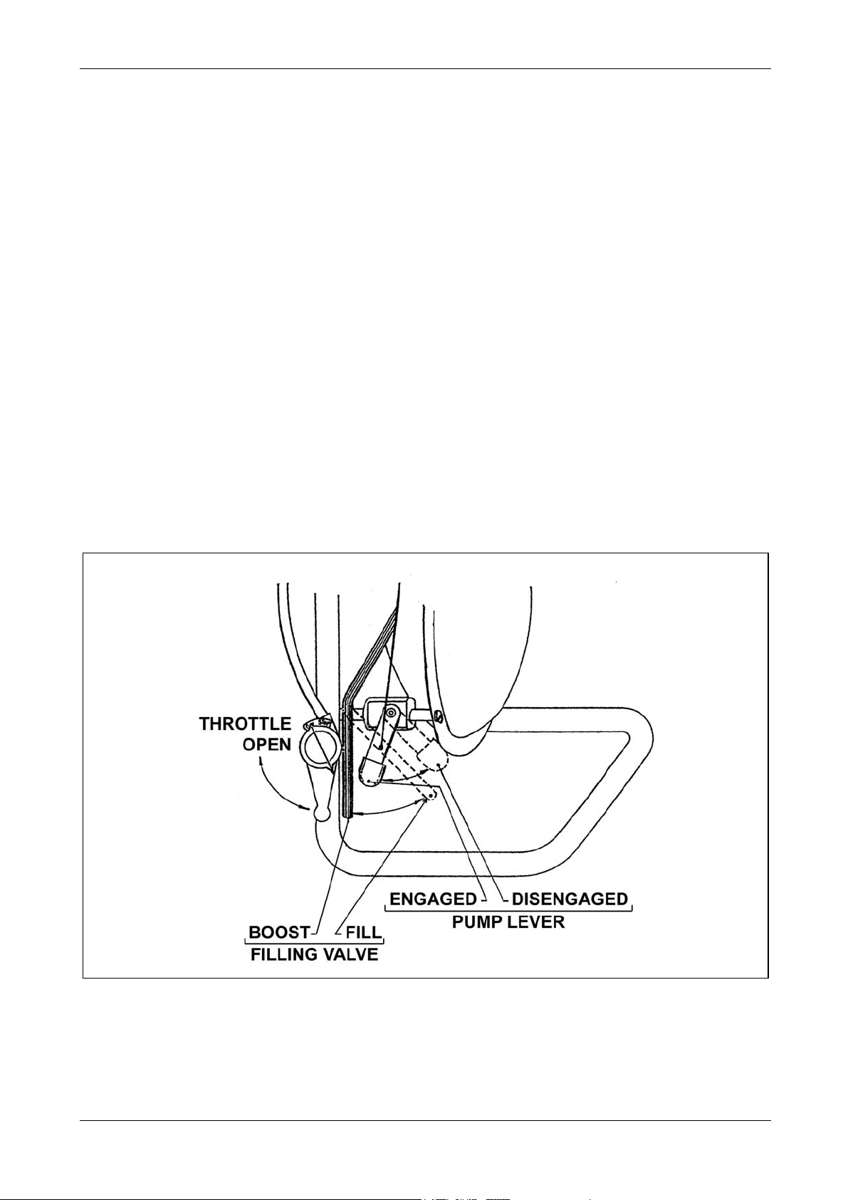
1. Before starting the sprayer, ensure that the chemical valve lever is in the BOOST
position and that the pump is DISENGAGED (see Fig. 2).
2. Start the sprayer as described in section 4.1.
3. When in the spraying area, move the pump lever to the ENGAGED position and
proceed as described in section 4.1.
Fig. 2 – Controls for Pump and Suction Filling Valve
MICRONAIR AU8000 SPRAYER
Page 8

6
4. If possible, avoid completely emptying the spray tank. Should the tank become
empty, DISENGAGE the pump IMMEDIATELY to avoid the possibility of damage by
running dry.
NOTE: The output of the sprayer with the pump running will be higher than with no
pump. See section 6.1 for full details.
4.3. Operation of Sprayer with Filling Pump
This section applies only to sprayers fitted with the optional pump and suction filling facility.
1. Pour about 0.5 litre of chemical into the tank and close the cap. This is only
necessary before the first filling.
2. Ensure that the pump lever is DISENGAGED.
3. Set the valve lever to the FILL position (see Fig. 2).
4. Start the engine (see section 4.1) and put the sprayer on the operator's shoulders.
5. Place the foot valve of the suction hose into the chemical container. Check that there
are no air bubbles in the suction hose.
6. Set the engine throttle to mid-position. DO NOT use the engine at full throttle when
filling. This is the only time that the engine should be run at half-throttle.
7. ENGAGE the pump lever to draw chemical up the suction hose and into the tank.
8. When sufficient chemical is in the tank, DISENGAGE the pump, set the throttle to idle
and move the valve lever to the BOOST position.
9. After spraying, use the filling pump to draw 2 – 3 litres of clean water or solvent into
the tank. This liquid should be sprayed through the sprayhead to clean the system.
Only spray this cleaning liquid onto the crop or in the sprayed area. DO NOT
CONTAMINATE AN OFF-TARGET AREA.
5. HEALTH AND SAFETY
The AU8000 sprayer must be used by a qualified operator in accordance with the
recommendations and statutory requirements for the use of sprayers and the chemical
being sprayed.
These requirements will be set out in the applicable local legislation and in the label of the
chemical.
In the United Kingdom, the precautions and regulations concerning the use of pesticides
and sprayers are defined in the Code of Practice for the Use of Pesticides on Farms and
Holdings (Published by HMSO for the Ministry of Agriculture, Fisheries and Food and the
Health and Safety Commission).
The use of pesticides and sprayers are subject to legislation or codes of practice in most
other countries. It is the responsibility of the user to ensure that these are read,
understood and complied with.
MICRONAIR AU8000 SPRAYER
Page 9

7
The following recommendations are for guidance only and do not exclude any statutory
requirement:
1. Always wear adequate protective clothing, eye protection and respiratory protection
when mixing, transferring or spraying pesticides. The minimum level of protection will
be stated on the chemical label or in the Code of Practice in most countries.
2. Protective clothing, respirators etc must be removed as soon as exposure to
pesticides has ceased. All items must be washed or disposed of safely according to
the manufacturers' recommendations.
3. Ensure that the sprayer is correctly calibrated for the chemical, application technique
and crop or pest being sprayed.
4. Take note of the speed and direction of the wind. Ensure that spray droplets do not
drift on adjacent crops, another person's land or an inhabited area. Always spray
downwind to avoid operator contamination. Never walk through a sprayed area.
5. All traces of chemical must be washed from the operator's skin immediately after
spraying and before eating, drinking or smoking.
6. Remove all traces of chemical from the tank, pipework and sprayhead as well as from
external surfaces of the sprayer.
7. All residues of chemical from the sprayer, pesticide containers or mixing vessels etc
must be disposed of safely by an approved means. Do not contaminate an off-target
area or allow pesticides to reach streams, wells or groundwater.
8. Dispose of empty chemical containers safely by an approved means. Do not keep
containers for re-use for other purposes.
MICRONAIR AU8000 SPRAYER
Page 10

8
6. CALIBRATION
As with any mistblower, an AU8000 sprayer must be calibrated before use. This involves
setting the correct output rate of chemical and adjusting the sprayhead to produce the
appropriate droplet size for the chemical and application technique being used.
The following sections describe the calibration of a standard Micronair AU8000 sprayer.
Some details of the procedures may differ if the sprayhead is used with a different model
of mistblower.
6.1. Output Rate of Chemical
The output rate of chemical from the sprayer will be determined by the required application
rate (in litres/hectare) and the area sprayed per minute (in hectares/minute).
The flow of chemical from the atomiser is controlled by the interchangeable restrictor tube
attached to the on/off valve and by the chemical pressure. Chemical is pressurised by air
from the blower fan and by the optional boost pump (if fitted).
The following steps describe the calibration procedure in detail:
1. Establish the average walking speed of the operator. This will depend upon, for
example, the target being sprayed, the evenness or slope of the ground, the amount
of chemical carried and the temperature.
The most accurate means of assessing walking speed is for the operator to spray the
actual crop or target in a 'trial run' with clean water. The speed can then be
calculated from the time to cover a measured distance.
2. Establish the width of the swath of spray on the target. In row crops or orchard
spraying this can often be determined by the number of rows sprayed at a time. In
public health or pest control spraying using a drift technique over open ground the
swath width must be determined by the use of sensitive cards or paper. These
should be placed both horizontally and vertically. The cards should be mounted
downwind of the spray line. The sprayer must be used under typical conditions of
wind and temperature.
When spraying field crops or open areas (e.g. for locust control), the distance
between successive passes of the sprayer should be less than the measured
maximum swath width to ensure adequate overlap of the spray and allow for
variations in the wind and terrain. For the purposes of calibration, the distance
between passes should be regarded as the swath width.
MICRONAIR AU8000 SPRAYER
Page 11

9
Fig. 3 – Coverage of Sprayer
3. Calculate the area treated by the sprayer per minute. Fig. 3 shows the sprayer being
operated over a field crop.
If the operator is walking at S Km/Hr this corresponds to 1000 x S metres/hour:
Distance travelled = 1000 x S metres/minute
60
If the width of the swath is W metres, then the area treated per minute is:
Area treated = 1000 x S x W sq metres/minute
60
This is converted to hectares by dividing by 10,000:
Area treated = 1000 x S x W = S x W ha/minute
60 x 10,000 600
This gives the standard formula for calculating the coverage of a sprayer:
Area/min = Swath Width (m) x Speed (Km/Hr) ha/min
600
MICRONAIR AU8000 SPRAYER
Page 12

10
Example:
Speed: 4 Km/Hour
Swath Width: 12 m
Therefore:
Area treated = S x W 4 x 12 = 0.08 ha/min
600 600
Table 1 shows the coverage of the sprayer for various swath widths and spraying
speeds.
4. Calculate the required output from the sprayer in litres/minute to give the correct
application rate for the chemical being used.
The output rate of chemical is given by the area sprayed (in hectares) per minute
multiplied by the required application rate in litres per hectare.
Example:
Coverage: 0.08 ha/min
Application rate: 2 litre/ha
Output = 0.08 x 2 = 0.16 litre/min
SWATH WIDTH (METRES) Speed
Km/hr
2
3
4
5
2 5 10 15 20 25 30 50
0.007 0.017 0.033 0.050 0.067 0.083 0.100 0.167
0.010 0.025 0.050 0.075 0.100 0.125 0.150 0.250
0.013 0.033 0.067 0.100 0.133 0.167 0.200 0.333
0.017 0.047 0.083 0.125 0.167 0.208 0.250 0.416
Table 1 – Coverage of Sprayer in Ha/min
5. Select the correct restrictor tube to give the required flow rate. Table 2 gives the
typical flow rate for each restrictor tube both with gravity feed and with the optional
boost pump operating. These figures are based on measurements with water. Actual
flow rates will depend upon the viscosity of the chemical being used. When the boost
pump is not used, the flow rate will also be affected by the height of the sprayhead
relative to the chemical tank. The rates in Table 2 are measured with the tank half full
and the sprayhead level with the engine.
FLOW RATE (LITRES/MINUTE) RESTRICTOR
NUMBER
1
2
3
4
5
Without boost pump With boost pump
0.075 0.40
0.150 0.80
0.300 1.60
0.600
1.200
Table 2 – Approximate Flow Rates for Restrictor Tubes
MICRONAIR AU8000 SPRAYER
Page 13

11
6. Fit a restrictor tube (8) to the outlet of the valve. Tighten the cap nut (14) firmly by
hand.
7. Push a 15 cm (6") length of 6 mm (¼") inside diameter plastic hose over the restrictor
tube.
8. Ensure that the chemical on/off valve is closed.
9. Fill the tank of the mistblower to half its normal working capacity with the chemical to
be used.
10. Start the engine of the mistblower and run it at the correct operating speed (see
section 4.1).
11. Support the sprayhead at its normal operating height.
12. Place a container under the tube fitted in step (7) and open the chemical on/off valve
until all air has been purged from the hose and valve. Close the valve.
13. Open the chemical valve again and collect chemical for a measured time of one or
two minutes. Use a measuring cylinder or calibrated container to measure output
rate in litres per minute.
14. Compare the measured output rate with the calculated rate from step (4).
15. If the actual output is slightly too high or too low, it may be possible to adjust it by
varying the tank air pressure control of the mistblower.
16. If this adjustment is insufficient or does not exist, the restrictor tube must be changed
to a smaller size to reduce the flow or a larger size to increase the flow.
17. The flow must always be re-checked after making any adjustments to the restrictor or
tank air pressure.
The above procedures assume that the operator can walk at a steady speed whilst
spraying. This may not be possible under some circumstances, such as when spraying
large trees. In these cases, the calibration and spraying techniques should be modified as
follows:
1. Calculate the number of trees per hectare.
2. Divide the chemical application rate in litres/Ha by the number of trees per hectare to
give the dose of chemical per tree.
Example:
Planting: 400 trees/ha
Application rate: 200 litre/ha
Dose = 200 = 0.5 litre/tree
400
3. Measure the time taken to spray one tree from all directions. Note that an adequate
time must be allowed for the airstream to carry spray droplets into the higher foliage.
4. Calculate the flow rate required to deliver the required dose in the measured time.
MICRONAIR AU8000 SPRAYER
Page 14

12
Example:
Dose: 0.5 L/tree
Time: 1.5 min/tree
Output = 0.5 = 0.33 litre/min
1.5
5. Calibrate the sprayer as described earlier.
6.2. Adjustment of Droplet Size
The size of the droplets produced by the sprayhead depends upon the rotational speed of
the atomiser and the properties of the chemical. The speed of the atomiser is controlled
by the velocity of air from the blower fan and by the angle of the fan blades.
As the mistblower is designed to run at a fixed blower speed, the speed of the atomiser
must be set by adjusting the angle of the fan blades.
All AU8000 sprayheads are supplied with the fan blades pre-adjusted to angle setting
number 2 (see Fig. 4). This setting should be satisfactory for the majority of applications.
If the droplet size is found to be too small, it can be increased by reducing the speed of the
atomiser by setting the fan blades to a coarser angle. Similarly, the droplet size can be
reduced by setting the fan blades to a finer angle and increasing the speed of the
atomiser.
The atomiser blade angle can be changed as follows. Numbers relate to Fig. 5.
1. Remove the screw securing the V-clamp ring (15) around the outer casing of the
sprayhead. Remove the front casing (2).
2. Remove the atomiser support ring (3) and atomiser from the rear casing whilst
pushing the feed hose through the grommet in the casing.
3. Remove the pipe clip (12) and atomiser feed hose (11). Slide the cone (5) off the
support ring.
4. Slacken the four atomiser clamp ring securing screws (118) just sufficiently to allow
the atomiser fan blades to be adjusted, see Fig. 6.
5. Adjust all four blades of the atomiser to a finer or coarser angle as required. See Fig.
4 for positions of setting marks. The blades should not be set finer than position 1 or
coarser than position 6. NOTE: For accurate alignment, the graduation mark and the
split line, view through the 10 mm hole in the atomiser support ring.
6. Tighten the clamp ring screws just sufficiently to trap the fan blades and prevent them
from moving. A torque of 0.3 nm (1 lb in) is sufficient. Overtightening the screws
could distort the hub or clamp ring.
MICRONAIR AU8000 SPRAYER
Page 15

13
Fig. 4 – Setting Marks on Blade
7. Reassemble the sprayhead by reversing steps (1 – 5).
8. Carry out a test by spraying the actual chemical to be used onto sensitive cards,
paper or slides. Check that the spray deposit is appropriate for the chemical and
application technique. Note that sensitive cards only give a good indication of the
number of droplets larger than about 60 microns. Smaller droplets may not mark
some types of card. The apparent size of droplets on the card will be larger than the
actual size due to spreading on the surface.
9. Note that the end cap of the gauze is provided with a conical recess in the centre.
This is intended to drive a hand-held tachometer to measure the speed of the
atomiser if required.
7. MAINTENANCE
Both the AU8000 sprayhead and the knapsack mistblower are designed for maximum
reliability and for a minimum of simple maintenance.
The following sections cover the sprayhead and general guidance for the mistblower
supplied with complete sprayers. Please refer to the Cifarelli maintenance manual for full
details of maintenance of the mistblower. If an alternative mistblower is used, refer to the
manufacturer’s maintenance instructions. The parts lists for the sprayhead and atomiser
are shown in section 8.
MICRONAIR AU8000 SPRAYER
Page 16

14
7.1. Knapsack Mistblower – Routine Maintenance
The mistblower will have a long and trouble-free life if it is kept clean and properly
adjusted. Attention must be given to the following points:
1. Chemical must NEVER be left in the tank or pipework. Always flush out the sprayer
with water or a solvent for the chemical used. Drain cleaning liquid from the sprayer
before storage.
2. Do not leave fuel in the tank or carburettor whilst the sprayer is in storage. After use,
close the fuel valve whilst the engine is running. When the engine stops, drain all
remaining fuel from the tank.
3. Check and clean the engine air filter every 50 hours (or less in dusty conditions). To
clean the filter, proceed as follows:
i) Open the filter casing and remove the foam filter.
ii) Wash the filter in petrol (gasoline).
iii) While still wet, pour about 5 ml of SAE 40/50 oil on the filter and squeeze well in.
iv) Allow all petrol to evaporate.
v) Re-assemble filter in casing.
4. Check and clean fuel filters. Note that the engine has two filters; one at the fuel valve
and one at the carburettor inlet.
5. Check the spark plug every 50 hours. If necessary, clean the spark plug and adjust
the gap setting to 0.4 – 0.5 mm. If the spark plug is damaged, replace with a new
plug of the correct type (see mistblower parts list).
7.2. Possible Engine Faults and Remedies
ENGINE WILL NOT START
Fault Remedy
1. Fuel valve closed Open valve
2. Lack of fuel Add fuel
3. Hole in the fuel tank cap obstructed Open hole
4. Engine flooded See starting instructions
5. Filter in the fuel cock or at the Clean filters
carburettor inlet is dirty
6. Carburettor float needle blocked Clean and check that needle
slides freely
7. Spark Plug contaminated with oil Clean
or carbon
8. Spark plug gap wrongly adjusted Adjust to 0.4 – 0.5 mm
MICRONAIR AU8000 SPRAYER
Page 17

UNSTEADY ENGINE RPM OR TENDENCY TO STOP
Fault Remedy
9. Loose spark plug Tighten spark plug
10. See points 5 - 8 above
11. Ignition lead damaged or not making Fasten or replace lead
contact
ENGINE IDLE UNSTEADY
Fault Remedy
12. Idle advance jet obstructed Clean
13. Idle advance screw requires adjustment Adjust
ENGINE DOES NOT DEVELOP MAXIMUM POWER
Fault Remedy
14. Carburettor jet contaminated Clean
15. Spark plug contaminated Clean and check gap
setting (0.4 - 0.5 mm)
16. Choke closed. Move lever to position A (see
starting instructions)
17. Filter in the fuel valve or at the Clean filters
carburettor inlet is dirty
18. Air filter dirty Clean
19. Exhaust hole obstructed. Remove exhaust and clean as far as
the exhaust hole in the cylinder
20. Air entering through gaskets of Tighten screws and nuts, replace
carburettor flanges, cylinder base etc gaskets if necessary
21. Wear of engine crankshaft seals Replace seals
EXCESSIVE VIBRATION
Fault Remedy
22. Broken blade on blower rotor Check rotor (a quick inspection
can be made by removing the
rear cushion)
23. Debris inside blower Open casing and clean
15
MICRONAIR AU8000 SPRAYER
Page 18

16
7.3. Maintenance of Sprayhead
The AU8000 sprayhead is built from chemical resistant materials and its simple design and
robust construction will ensure many years of trouble-free performance provided that it is
not mistreated and is properly cleaned after use.
The AU8000 atomiser is dynamically balanced to ensure that it will run smoothly without
vibration. Some chemicals, particularly certain ULV formulations, can dry or crystalise on
the gauze, blocking the mesh and causing the atomiser to vibrate. This can easily be
avoided by spraying 1 – 2 litres of liquid from the atomiser at the end of each spray job.
The liquid must be a solvent for the chemical which has been used. Water will normally
only dissolve water-based formulations. kerosene or diesel fuel is suitable for most ULV
products.
The bearings of the AU8000 are sealed and are lubricated for life. The bearings should be
replaced if they become worn.
If it is necessary to replace the bearings or any other part, the procedure to dismantle the
sprayhead is as follows (see Fig. 5):
NOTE: DO NOT remove bearings unless worn.
1. Remove the inlet hose (11) from the restrictor tube on the chemical valve.
2. Loosen the handle clamping screws and slide the handle and sprayhead off the air
inlet tube (19).
3. Remove the bolt of the V clamp (15) and remove the ring from the outer casing.
4. Pull the two halves of the outer casing apart and remove the atomiser (1) and its
support ring (3). Push the feed hose through the grommet in the housing whilst
withdrawing the atomiser
5. Remove the pipe clip (12), inlet hose (11) and cone (5).
6. Remove the pipe union (7) and atomiser securing nut (112). Slide the atomiser from
the support ring.
To dismantle the atomiser, proceed as follows (see Fig. 6):
7. Remove the four screws (118) from the blade clamp ring (103), lift off the ring and
remove the blades.
8. Remove the three screws (122) securing the cap and deflector assembly (105). Pull
the cap from the end of the gauze and push the spindle (102) through the atomiser.
9. If it is necessary to remove the gauze, insert a screwdriver through the holes in the
rear of the gauze and take out the three screws (120) securing the gauze to the hub.
10. If it is necessary to remove the bearings, use a pair of circlip pliers to remove the
circlip (117) the wavy washer (121) and the sealing ring (110) from the front of the
hub. Next, push an aluminium or brass drift against the inner part of the rear bearing
and tap both bearings out through the front of the hub. Ensure that the hub (101) and
spacers (106 and 107) are not damaged or lost.
MICRONAIR AU8000 SPRAYER
Page 19

17
After dismantling the atomiser, the following should be checked:
Gauze (104) – Free of dents or chemical contamination
Bearings (113) – Both in good condition. If one bearing is faulty, both
must be replaced
Tolerance Rings (116) – Not cracked or deformed
Bearing Spacers – Not corroded or worn
(106 and 107)
V-Ring Seal (114) – In good condition and not cut or worn
Nilos Ring (115) – Not worn or bent
Any worn and damaged parts must be replaced with genuine Micronair spares. Any
attempt at local repair or the use of substitute parts could seriously damage the unit and
impair its performance.
The procedure to re-assemble the atomiser and sprayhead is the reverse of the
dismantling procedure. It is important that the following points are observed.
1. Fill the recess of the Nilos ring and the brass sealing (110) ring with grease. The
bearings, spacers and lip of the V-Ring should also be coated with a thin film of
grease before assembly.
NOTE: When new bearings are fitted a new Nilos ring should be fitted.
2. The bearings must be pressed squarely into the hub and must not be allowed to
become mis-aligned. They must NOT be driven in with a hammer.
3. The clamp ring (103) must be assembled in the correct position with the dimples in
the ring and hub body aligned.
NOTE: Item numbers 1 – 20 refer to Fig. 5 and item numbers 101 – 122 refer to Fig. 6.
MICRONAIR AU8000 SPRAYER
Page 20

8. PARTS LISTS
When ordering spare parts, please specify the following information:
Serial number of sprayhead or engine
Approximate date of purchase
Description of part
Part number as shown in this section
Number of parts required
8.1. AU8000 Sprayhead
Item Part No Description Quantity
1 EX3678 AU8000 Atomiser Assy 1
2 EX3682 Front Casing Assy 1
3 EX4032 Support Ring 1
4 EX3681 Rear Casing 1
5 EX4017 Cone 1
6 EX2192 Nut 1
7 EX3673 Nipple 1
8 EX4035-39 Restrictor Tubes 1 set (5)
9 CBP1712 'O' Ring 1
10 CBP1725 Grommet 1
11 CBP1637 Tube 5 mm bore 10 mm O/D 15"
12 CBP1634 Pipe Clip (½") 2
13 CBP1713 Handle Assy 1
14 CBP1714 Cap Nut 2
15 CBP1628 'V' Clamp 1
16 CBP1630 Filter 1
17 EX4040 Pipe Nipple 1
18 EX2275 Bush 1
19 CBP1661 Air Inlet Tube – Straight 1
20 CBP1717 Pipe Clip (2 ¾") 2
18
MICRONAIR AU8000 SPRAYER
Page 21

19
Fig. 5 – AU8000 Sprayhead
MICRONAIR AU8000 SPRAYER
Page 22

8.2. AU8000 Atomiser
Item Part No Description Quantity
101 EX3666 Hub Drive Tube 1
102 EX3677 Spindle Assy 1
103 EX3669 Clamp Ring 1
104 EX3676 Gauze Assy. 1
105 EX3775 Deflector Cap Moulded type 1
106 EX3685 Inner Spacer 1
107 EX3686 Outer Spacer 1
108 EX3670 Spacer Bush 1
109 EX4404 Blade 4
110 EX5044 Sealing Ring 1
111 CBP1416 Washer 1
112 CBP1721 Stiffnut 1
113 CBP776 Bearing 2
114 CBP777 V-Ring Seal 1
115 CBP774 Nilos Ring 1
116 CBP808 Tolerance Ring 2
117 CBP2107 Circlip 1
118 CBP1720 Screw 4
119 SP127C Washer 4
120 EX2612 Bolt 3
121 EX5062 Wavy Washer 1
122 A206-C10 Screw 3
20
MICRONAIR AU8000 SPRAYER
Page 23

21
Fig. 6 – AU8000 Atomiser
MICRONAIR AU8000 SPRAYER
Page 24

22
9. CONVERSION FACTORS
1 yard = 3 feet = 0.91 metre
1 metre = 39.37 inches = 1.09 yards
1 statute mile = 0.87 nautical mile = 1.61 kilometres
1 nautical mile = 1.15 statute mile = 1.85 kilometres
1 kilometre = 0.62 statute mile = 0.54 nautical mile
1 statute mile = 1760 yards = 5280 feet
1 nautical mile = 2027 yards = 6081 feet
1 kilometre = 1094 yards = 3282 feet
1 metre/sec = 2.237 miles per hr = 196.9 ft/min
1 acre = 43560 sq feet = 4840 sq yards
1 acre = 4047 sq metres = 0.40 hectare
1 hectare = 107600 sq feet = 11955 sq yards
1 hectare = 10000 sq metres = 2.47 acres
1 sq mile = 640 acres = 259 hectares
1 sq kilometre = 247 acres = 100 hectares
1 US gal = 0.83 Imp gal = 3.78 litres
1 Imp gal = 1.20 US gals = 4.54 litres
1 litre = 0.26 US gal = 0.22 Imp gal
1 US pint = 16 US fl ounces = 0.47 litres
1 Imp pint = 20 Imp fl ounces = 0.57 litre
1 US gal/acre = 8 US pint/acre = 9.45 litres/hectare
1 Imp gal/acre = 8 Imp pints/acre = 11.35 litres/hectare
1 litre/hectare = 0.11 US gal/acre = 0.081 Imp gal/acre
1 pound = 16 ounces = 0.45 kilogram
1 kilogram = 2.20 pounds = 35.3 ounces
1 ounce = 28.35 grams
1 pound/sq inch = 0.068 atmosphere = 0.067 bar
1 atmosphere = 14.70 pounds/sq in = 1.01 bar
1 bar = 14.50 pounds/sq in = 0.98 atmosphere
Every care has been taken in the design of this equipment and the preparation of this
Handbook. However, Micron Sprayers Limited cannot accept responsibility for errors or
the consequences thereof. The user must satisfy himself that the equipment is suited to
his needs and is performing according to his requirements.
MICRONAIR AU8000 SPRAYER
Page 25

 Loading...