

Page 1
© COPYRIGHT 2018, MICRONOR INC.
CAMARILLO, CALIFORNIA
UNITED STATES OF AMERICA
MR430 Series
ZapFREE
®
Fiber Optic
Absolute Encoder System
Instruction Manual
Doc No: 98-0430-11
Revision A3 dated 17-August-2018
MICRONOR INC.
900 Calle Plano, Suite K
Camarillo, CA 93012 USA
PH +1-805-389-6600
FX +1-805-389-6605
www.micronor.com
For Support in Europe:
MICRONOR AG
Pumpwerkstrasse 32
CH-8105 Regensdorf
Switzerland
PH +41-44-843-4020
FX +41-44-843-4039
www.micronor.com
Notice of Proprietary Rights
The design concepts and engineering details embodied in this manual, which are the property of
MICRONOR INC., are to be maintained in strict confidence; no element or detail of this manual is to be
spuriously used, nor disclosed, without the express written permission of MICRONOR INC. All rights are
reserved. No part of this publication may be reproduced, stored in a retrieval system, or transmitted in
any form or by any means, electronic, mechanical, photocopying, recording, or otherwise, without prior
written permission from MICRONOR INC.
Page 2

MICRONOR INC.
MR430 Fiber Optic Position Sensor System
Page 2 of 50
Revision History
Revision
Date
Notes
A
8-March-2018
Initial Release
A1
21-June-2018
Product release
A2
11-July-2018
Added MR431 sensor diagrams
A3
17-Aug-2018
Added System Loss Budget to MR430 Controller specifications
Page 3

MICRONOR INC.
MR430 Fiber Optic Position Sensor System
Page 3 of 50
Table of Contents
1. Product Description ............................................................................................. 5
1.1 Position Sensor Background ......................................................................................... 5
1.2 Fiber Optic Position Sensor .......................................................................................... 5
1.3 Features ......................................................................................................................... 6
2. Initial Preparation ................................................................................................. 7
2.1 Unpacking and Inspection ............................................................................................ 7
2.2 Damage in Shipment .................................................................................................... 7
2.3 Standard Contents ........................................................................................................ 7
3. Installation and Operation .................................................................................... 8
3.1 Mounting the Sensor Unit ............................................................................................. 8
3.2 Mounting the Controller Unit ........................................................................................ 9
3.3 USB (J2) and RS485/SSI Interface Connections (J3) ................................................... 11
3.4 Optical Connection ..................................................................................................... 12
3.5 Blink Status and Error Codes ...................................................................................... 12
3.6 System Start-Up Without PC Computer ..................................................................... 13
3.7 Functional System Overview ....................................................................................... 14
3.8 Turn-Counter and Turn-Counter Size .......................................................................... 16
3.9 Multi-Turn Operation .................................................................................................. 17
3.10 Battery Backup for Multi-Turn Operation ................................................................... 17
3.11 SSI Interface ................................................................................................................ 18
3.12 Voltage Output ........................................................................................................... 20
3.13 Isolated Current Output (4-20mA) .............................................................................. 22
3.14 Digital Set Point .......................................................................................................... 23
4. Serial Communication – Modbus ....................................................................... 25
4.1 USB-Serial Emulator .................................................................................................... 25
4.2 Serial Interface Specification ....................................................................................... 26
4.3 Physical Connection for Modbus operation ............................................................... 26
4.4 Serial Bus Termination Resistor ................................................................................... 27
4.5 MODBUS Communications Protocol .......................................................................... 27
5. MR430 - Error Handling and Troubleshooting .................................................... 33
5.1 Explanation of Status and Error Handling ................................................................... 33
5.2 Explanation of Status and Error Indication ................................................................. 33
5.3 Reading the Error Counters ........................................................................................ 38
5.4 About Statistical Read Error Determination ................................................................ 38
5.5 Warranty Information .................................................................................................. 40
6. Specifications ..................................................................................................... 41
6.1 MR430 Controller Specification .................................................................................. 41
6.2 MR431 Sensor Specifications ...................................................................................... 42
Page 4

MICRONOR INC.
MR430 Fiber Optic Position Sensor System
Page 4 of 50
7. ZapView®-MR480 Software ............................................................................... 43
8. MR430 Theory of Operation ............................................................................... 43
9. Mechanical Reference Drawings ......................................................................... 44
9.1 MR430-1 Controller ..................................................................................................... 44
9.2 MR431 Sensor ............................................................................................................. 44
9.3 MR439 M-POF Cabling ............................................................................................... 44
List of Figures
Figure 1. Micronor MR430 Fiber Optic Position Sensor System ................................................. 5
Figure 2. Three Methods of Mounting MR431 Sensor – (a) Synchro Mount with Clamps, (b) Synchro Mount
with Flat Washers, and (c) Face Mount. ............................................................................... 8
Figure 3. Mounting MR430 Controller on DIN Rail ..................................................................... 9
Figure 4. Connections to MR430-1 Controller ........................................................................... 10
Figure 5. Location of RS485/Modbus RTU, SSI and USB Connections ..................................... 11
Figure 6. J3-Connector Pin Assignments ................................................................................... 11
Figure 7. Plug for J3 Connector ................................................................................................. 11
Figure 8. Location of Recessed Home Button ........................................................................... 13
Figure 9. Block Diagram of MR430 System ............................................................................... 14
Figure 10. Suggested Battery Backup Circuit ............................................................................ 17
Figure 11. SSI Interface Connector – J3 (10 pin). ...................................................................... 18
Figure 12. SSI Single Transmission Timing ................................................................................ 19
Figure 13. Mode 1 Voltage Output ........................................................................................... 20
Figure 14. Mode 2 Voltage Output ........................................................................................... 20
Figure 15. Mode 3 Voltage Output ........................................................................................... 21
Figure 16. Analog Output With An Oscillating Shaft Input ....................................................... 21
Figure 17. Isolated 4-20mA Connection ................................................................................... 22
Figure 18. Mode 1 Current Output............................................................................................ 22
Figure 19. Mode 2 Current Output............................................................................................ 23
Figure 20. Block Diagram of the Fiber Optic Position Sensor System ...................................... 43
List of Tables
Table 1. Table of Error Codes .................................................................................................... 35
Page 5
MICRONOR INC.
MR430 Fiber Optic Position Sensor System
Page 5 of 50
1. Product Description
1.1 Position Sensor Background
Position sensors are typically used to provide an absolute position from a mechanical moving device to a
controller unit. The position information is either used to measure a position or to close the servo loop for
an automatic positioning system. The key characteristics of an absolute position sensor are:
• Range
• Accuracy
• Resolution
• Time response of the actual position
1.2 Fiber Optic Position Sensor
The MR430 series fiber optic position sensor system is an innovative all-optical design immune to any
electro-magnetic interference such as lightning, radiation, magnetic fields and other harsh environmental
conditions. The fiber optic aspect of the sensor also makes it perfectly suited for sensing position at high
voltage power lines, within high magnetic fields (MRI) or explosive atmospheres. This innovative product
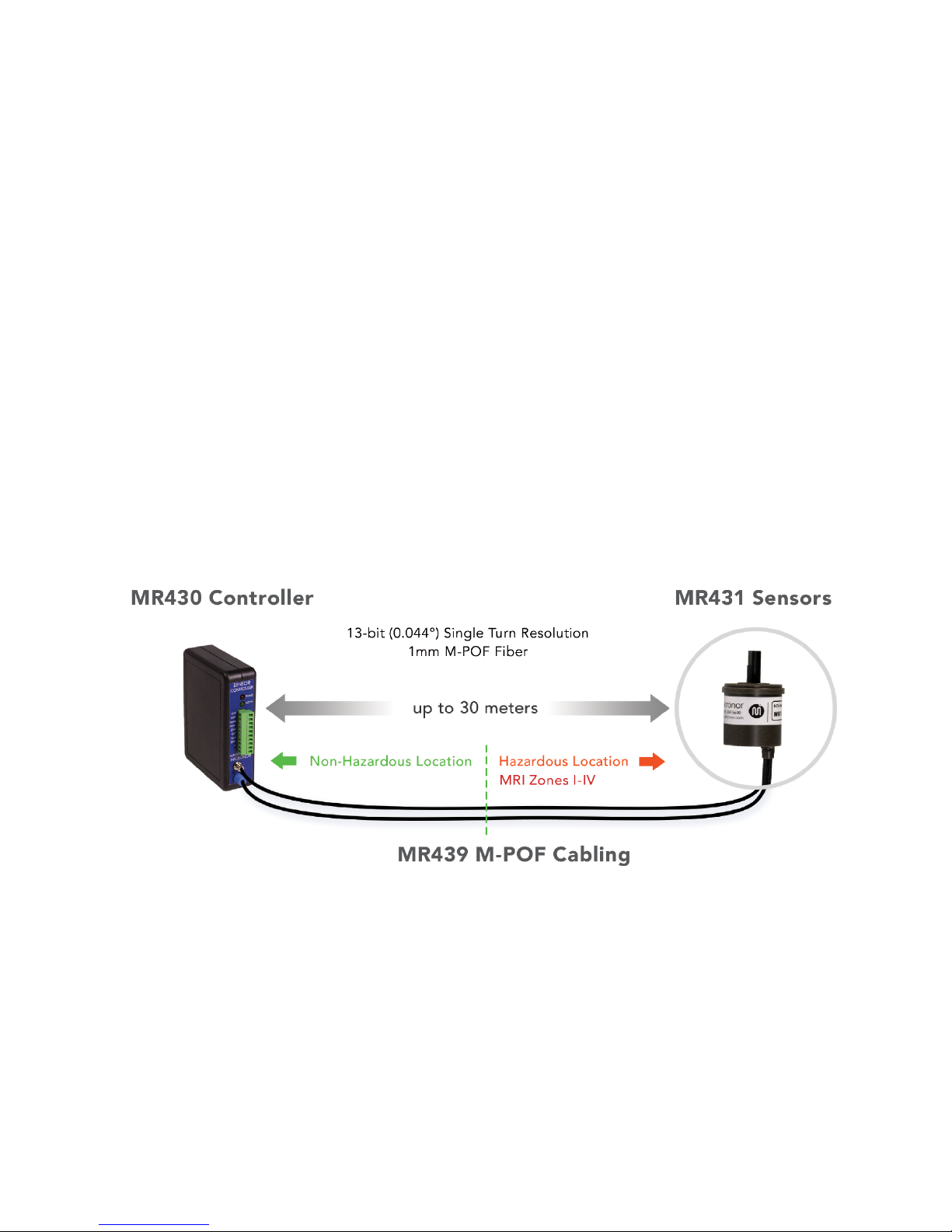
measures absolute angular position from 0° to 360° with 13-bit resolution and distances up to 100 feet.
Figure 1. Micronor MR430 Fiber Optic Position Sensor System
The sensor utilizes Plastic Optical Fiber for sensing the exact position of the sensor disk. There are two
fibers, the Transmit fiber sends a short light pulse of light at a wavelength of 645nm to the sensor. A unique
code on the sensing disk impresses the code image to the receiving imaging fiber. The controller analyzes
the code impressed on the Receiving fiber and determines the exact position. Since the sensor is
electrically passive, it can be deployed in EMI/RFI intense environment without being disturbed by such
interference.
The position signal is measured and updated at a rate of 1.2 kHz. The controller provides a host of
interface capabilities, including: scalable analog voltage and current outputs, digital SSI (Serial
Synchronous Interface) output, USB, and a Modbus compatible serial interface.
Page 6

MICRONOR INC.
MR430 Fiber Optic Position Sensor System
Page 6 of 50
1.3 Features
• Absolute Angular Position with 13-bit (8192) Resolution
• Multi-turn tracking to 12-bits (4096 turns)
• Immune to Electrical Interference
• Zero Emitted Electrical Radiation
• MRI Safe Sensor, Non-Metallic
• Transmission without Interference up to 30m (100 feet)
• Utilizes 1mm diameter POF fibers
• Multiple interfaces built-in into one unit
o SSI Interface
o Modbus RTU via RS422/RS485 serial interface.
o USB Interface
o Two Scalable Analog Position Outputs (±10V and 4-20mA)
o One Programmable Digital Set-Point
• User settable Zero Position
• External Zero Position input.
• Powers from +18V DC to +28VDC
• Low Energy consumption, < 1.5 Watts
• ZapView®
Setup Software
• Small form factor Sensor (size 11)
• Ex classified “Inherently Safe, Simple Mechanical Device”, i.e. sensor can be installed in all manner
of hazardous location or combustible atmosphere – mines, gas, vapors or dust.
Page 7

MICRONOR INC.
MR430 Fiber Optic Position Sensor System
Page 7 of 50
2. Initial Preparation
2.1 Unpacking and Inspection
The unit was carefully inspected mechanically and electrically before shipment. When received, the
shipping carton should contain the following items listed below. Account for and inspect each item before
the carton is discarded. In the event of a damaged instrument, write or call your nearest MICRONOR office
in the U.S. A. Please retain the shipping container in case reshipment is required for any reason.
2.2 Damage in Shipment
If you receive a damaged instrument you should:
1. Report the damage to your shipper immediately.
2. Inform MICRONOR
3. Save all shipping cartons.
Failure to follow this procedure may affect your claim for compensation.
2.3 Standard Contents
MR431 Sensor:
• MR431 Sensor Device with customer-specified POF pigtail length
• Test Protocol Sheet
• Instruction Manual (this document, one soft copy supplied with each shipment)
MR430-1 SSI Controller Module:
• MR430-1 Controller Module
• Detachable Phoenix Terminal connector plugged into unit.
• ZapView
®
430 Instruction Manual (Paper Copy)
• MR232-3 USB Cable
• The following documents are supplied on a CDROM or USB Stick:
o MR430 ZapFree
®
Fiber Optic Absolute Encoder Instruction Manual (PDF file)
o ZapView
®
430 Setup Software
o ZapView
®
430 Instruction Manual
Available accessories (must be ordered separately):
• MR431A - set of 3, non-metallic synchro clamps and screws
• MR430-99-01 (J2) Breakout Cable for connection to SSI and RS485 interfaces
• MR498 cable assemblies (for extended links)
• MR498 inline mating adapters for use with MR498 extension assemblies
Page 8
MICRONOR INC.
MR430 Fiber Optic Position Sensor System
Page 8 of 50
3. Installation and Operation
3.1 Mounting the Sensor Unit
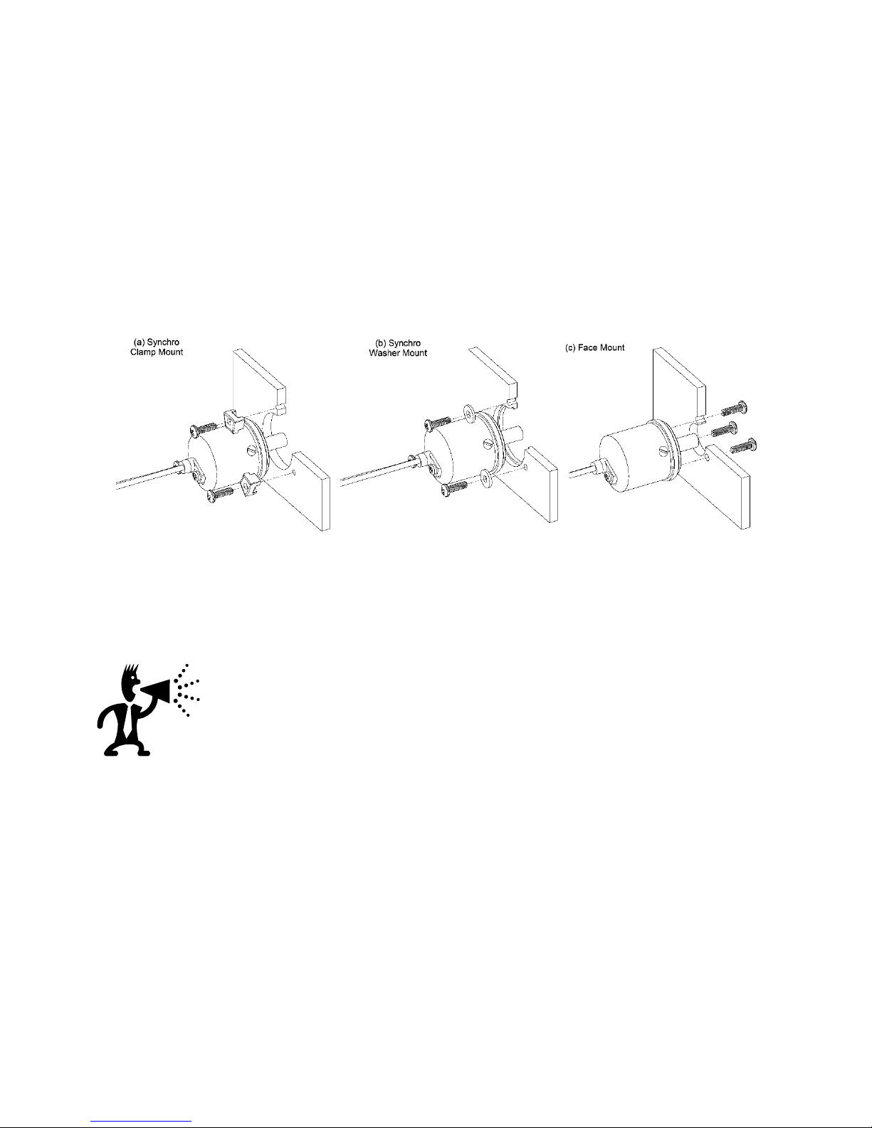
The MR431 sensor unit is a Size 11 standard servo mount configuration with Ø6mm shaft. Figure 2
illustrates 3 methods of mounting the sensor. Detailed mounting instructions and dimensions can be found
in the MR431 Reference Drawing in Section 9.2.
a) Synchro clamps (set of 3x clamps and screw available as Micronor P/N MR431-1101)
b) Flat washers
c) Face mount
Figure 2. Three Methods of Mounting MR431 Sensor – (a) Synchro Mount with Clamps, (b)
Synchro Mount with Flat Washers, and (c) Face Mount.
IMPORTANT NOTES
The sensor requires secure installation to meet published specifications.
No excessive force or load should be applied while installing.
The sensor should be mounted to a flat surface or bracket.
A flexible shaft coupling should be used when mounting to an external motor shaft.
Page 9
MICRONOR INC.
MR430 Fiber Optic Position Sensor System
Page 9 of 50
3.2 Mounting the Controller Unit
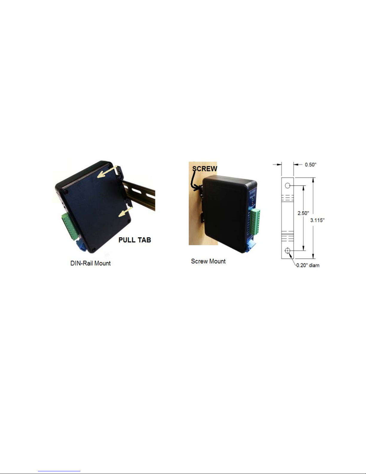
The controller unit mounts on standard 35mm DIN rail, or it can be screw mounted to a wall or cabinet.
• For DIN rail mounting, insert clip to the unit and then clip onto DIN rail by bending the clip tabs
toward of the enclosure.
• When screw mounting, remove clip from enclosure and use screws to affix clip to the wall and
then clip enclosure onto the plastic clip. Both mounting schemes are shown below.
IMPORTANT:
• The optical power emitted by the Controller is classified both Eye-Safe (Class 1) and Inherently
Safe (Ex op is).
• By design, the optoelectronic Controller must be installed in a non-hazardous, Safe Area.
Figure 3. Mounting MR430 Controller on DIN Rail
Page 10
MICRONOR INC.
MR430 Fiber Optic Position Sensor System
Page 10 of 50
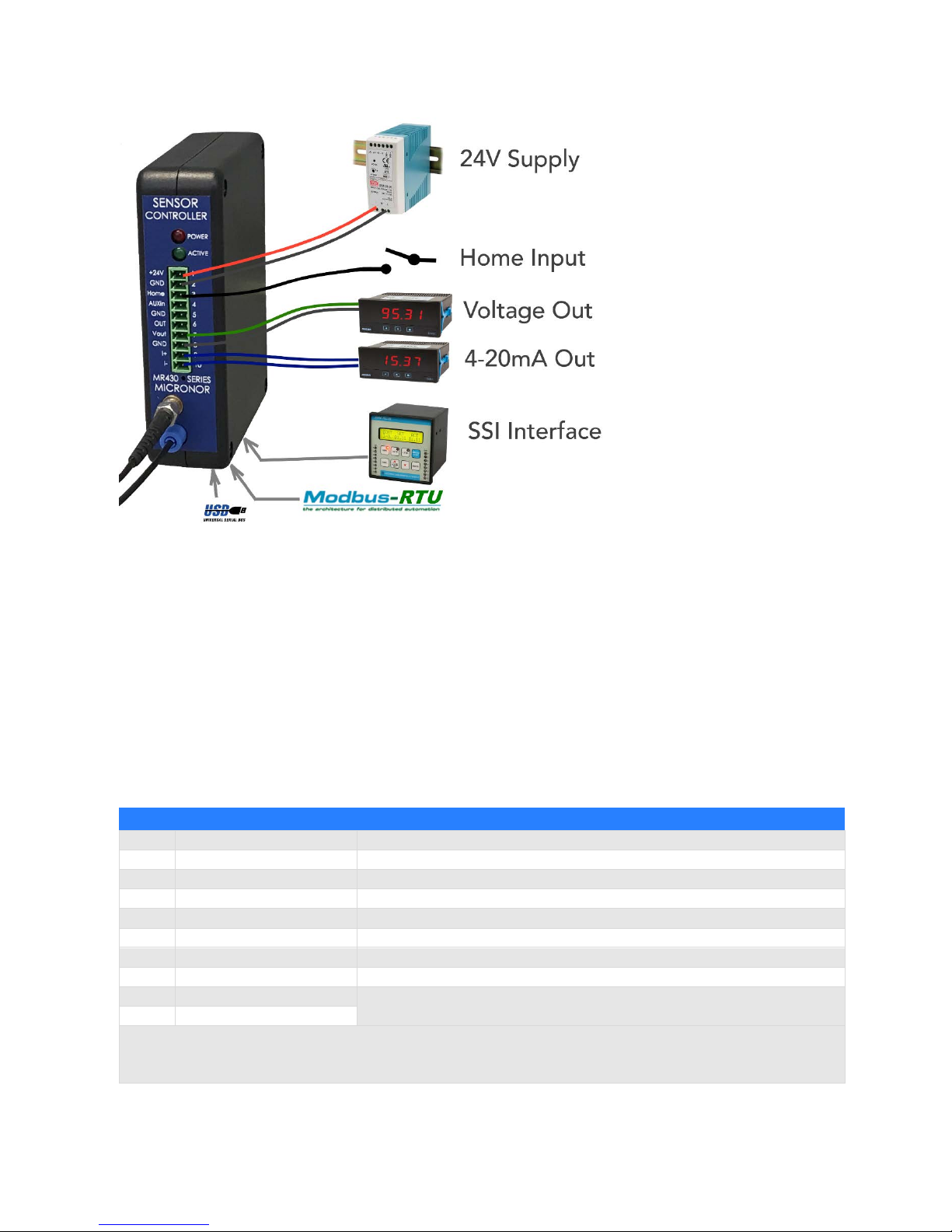
The Sensor Controller requires
24V DC and consumes
approximately 60mA.
A number of interface options
exist:
Voltage and current outputs are
scalable using the ZapView®
software.
The 4-20mA current output is
isolated and requires an external
voltage source.
The Homing input requires a
18V to 24V logic or switch signal.
Figure 4. Connections to the MR430-1 Controller
The SSI interface usually connects to a PLC, servo drive unit or other position indicator. The SSI allows for
clock speeds of up to 250kHz and block read-out speeds up to 10kHz. Signals are available on connector
J3 which is shared with the Modbus interface signals.
The Modbus/RTU interface is available at connector J3. Controller units are slave devices and the device
address is programmable via this interface or the USB interface. Standard Baud rate is 57,600, 1 Stop Bit,
No Parity. The default Common Device Address is 235.
The USB interface is a serial FTDI Virtual Communications Port (VCP) serial emulator. It operates exactly
the same way and the protocol must be Modbus/RTU. Whenever the USB is connected and active, the
Modbus/Interface is disabled.
Electrical Connections to the Sensor Controller (J1)
1
+24V
Power Supply, 65mA typical
2
GND
3
Home
24V signal will set position to pre-defined value. (normally 0)
4
AUXin
24V signal. Reserved for future use.
5
GND
6
Set Point Out
5V Logic, goes Hi if a user-defined set point is reached.
7
Voltage Position Out
-10V to +10V, user defined scale based on position
8
GND
9 I (+)
4-20mA isolated current loop, user defined scale based on position,
user must provide a voltage source.
10
I (-)
Detachable Screw Terminal accepts 14 to 30AWG wires
Mating Terminal Connector: Phoenix P/N 1803659 (one supplied with unit)
Figure 4. Connections to MR430-1 Controller
Page 11
MICRONOR INC.
MR430 Fiber Optic Position Sensor System
Page 11 of 50
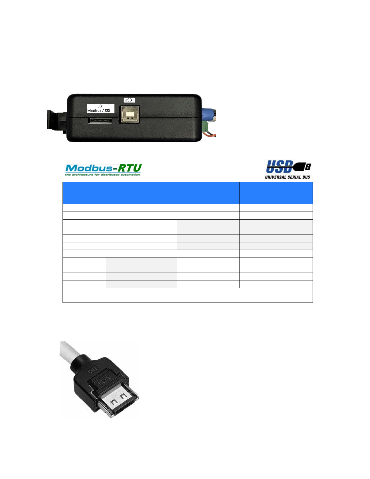
3.3 USB (J2) and RS485/SSI Interface Connections (J3)
Connector J2 provides the USB interface with Type B connection.
Connector J3 provides both RS485 and SSI interfaces.
Figure 5. Location of RS485/Modbus RTU, SSI and USB Connections
Figure 6. J3-Connector Pin Assignments
Default Baud rate is: 57600, 8 bit data, 1stop bit, no parity bit
Connector Plug: Hirose P/N 3240-10P-C(50)
Digikey P/N H11343-ND
Mouser P/N 798-324010PC50
Recommended Cable:
Tensility International P/N 30-00534
Digikey P/N T1355-5-ND
Micronor P/N MR430-99-01 (available separately) is a pre-assembled
pigtail assembly with 1m pigtail
RS485
Via J2
SSI
Via J2
(Optional)
MR430-99-01 Wire
Color Code
Pin
Function
Function
Color
1
+5V
+5V
Brown
2
RS422 – RCV- (input)
Red
3
RS422 – RCV+(input)
Orange
4
RS422 – TX- (output)
Yellow
5
RS422 – TX+(output)
Green
6
GND
GND
Blue
7 SSI-CLK-
Purple
8 SSI-CLK+
Grey
9 SSI-DAT-
White
10 SSI-DAT+
Black
NOTE: Pin 1 (+5V Power) can be used to power an RS232 to RS485 converter module.
Figure 7. Plug for J3 Connector
Page 12
MICRONOR INC.
MR430 Fiber Optic Position Sensor System
Page 12 of 50
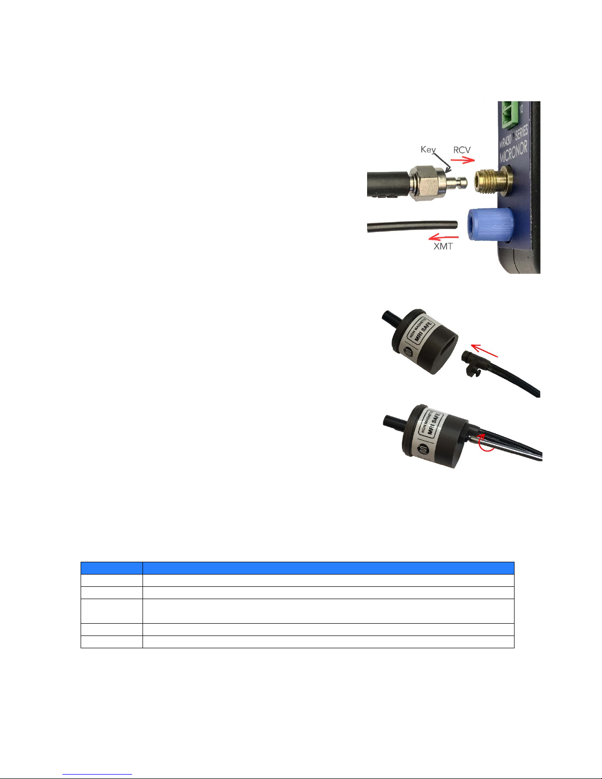
3.4 Optical Connection
The system uses two POF fibers:
a.) Transmit fiber is a standard 1mm POF fiber. On controller
this fiber connects straight into the blue LED transmitter
receptacle. Push fiber all the way to the stop and then
gently lock the blue collar nut.
b.) Receive fiber is a plastic optical imaging fiber (POIF). On
the controller the end is terminated and has a high quality
polished finish. (do not scratch). The fiber is terminated
into an SMA connector with a key. Locate the key and
insert connector all the way and hand tighten the SMA
hex nut.
On the sensor end, the two POF fibers terminate into a special
purpose connector. This connector end is polished and must be
protected from scratches and contamination. This connector is a
service connector only, and it should be disconnected only when
mounting or servicing the sensor.
When sensor is disconnected cover sensor opening with a tape.
3.5 Blink Status and Error Codes
Status information is provided by a blinking PWR LED.
See Section 5 for more details regarding status and error codes.
Blinks
Code Description
Steady ON
System is ok. Shaft position within measuring range
1
Outside Range for Turn-Restore
2
Bad position signal.
-> Sensor may need to be “paired” to the controller box
3
No optical signal, i.e. Fiber disconnected
4
System Problem
The blinking LED status may be cleared by a momentary push on the Home/Reset button located
below the J1 connector.
Page 13
MICRONOR INC.
MR430 Fiber Optic Position Sensor System
Page 13 of 50
When the MR430 controller indicates an Error Blink Status, it is advisable to use the ZapView
®
430 software
to troubleshoot the problem. If not already installed on your computer, the current version of the software
can be downloaded from www.micronor.com
.
3.6 System Start-Up Without PC Computer
It is recommended to use a PC (laptop) computer when making the MR430 Position Sensing System
operational. Micronor provides the ZapView® software for setting parameters and performing diagnostics
of the system. Checking the system after installation with ZapView® provides assurance that the installation
is complete and the system functions perfectly.
There may be instances where no PC is available. Installations that use only the analog or SSI outputs, do
not require specific programming on-site, especially if the MR430 controller was pre-configured for the
customer's application at the factory - or the customer is using the default settings.
Install the sensor as described above, connect the fiber optic lines, and apply 24V to the MR430 controller.
Rotate the sensor through at least one full revolution. If the power LED remains ON steady state, it means
that all tests internal were completed successfully and the system is ready to go.
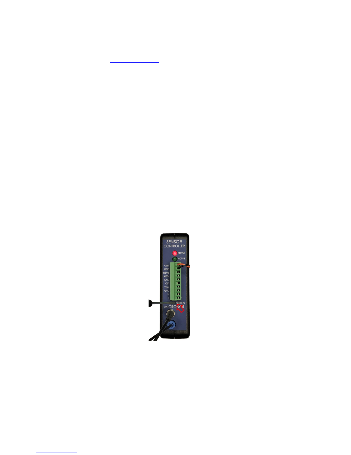
All that is left to do is to set the Home (Zero) position. Bring the system to the desired Home position, and
activate the recessed Home button located below J1, as shown in the figure below.
Note:
In case of an error, the LED power light will blink a specific error code. The first press of the Home
button will acknowledge the error signal. The second press will secure the Home position. (Pressing the
switch twice will always Home the unit.)
Figure 8. Location of Recessed Home Button
Page 14
MICRONOR INC.
MR430 Fiber Optic Position Sensor System
Page 14 of 50
3.7 Functional System Overview
The MR430 system consists of an all optical, non-electrical, passive sensor (MR431) which is connected to
the MR430 Controller via a duplex POF and POIF fiber assembly.
The MR430 Controller constantly interrogates the sensor by sending a short optical pulse to the sensor.
The sensor impresses a code corresponding to the actual shaft position on to the imaging fiber. The
MR430 controller receives this optical image and through computational algorithms determines the
absolute shaft position. The system is a “Single Turn Absolute” position sensor. However, the controller
provides mechanism which enables the system to function quasi multi-turn position sensor.
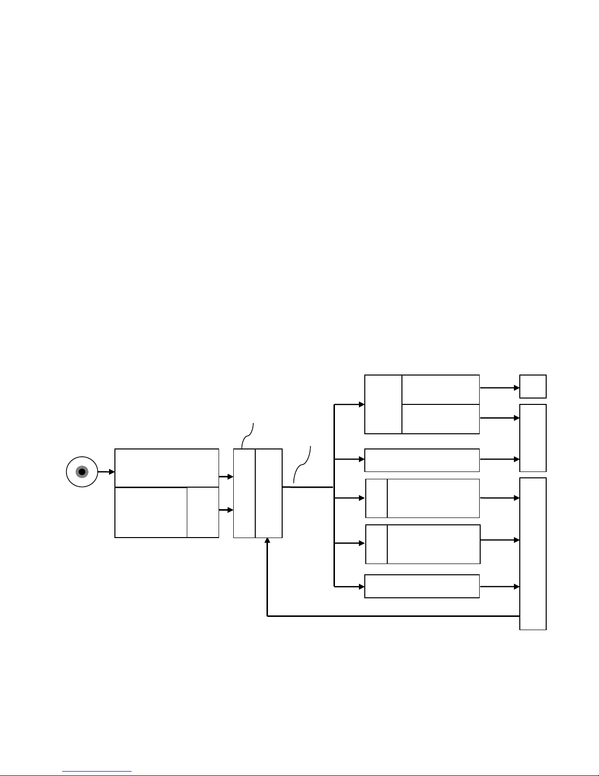
Figure 9 provides a block diagram of the MR430 system and its user interfaces. The single-turn resolution
is 13 bits and there is also a 12-bit turn counter which keeps track of the full turns of the sensor while the
unit is powered up and the sensor is connected with the fiber optic link. Absolute single-turn position (13
bits) and turn counter (12 bits) combine to provide a 25-bit position signal. The user has the option to
mask the turn counter and thus limit the output to match the physical setup. If the sensor is only used to
measure a range over , let’s say, 5 turns then the user may limit the turn counter to 3bits providing a range
of maximum 8 turns until the output wraps around back to zero. Using the example above, the readout
would be limited to 16bits (0 to 65,535) to cover the position range of (3 turns times 8192 resolution per
turn) 24,575 counts
As the block diagram shows, the position signal is routed to all the various output interfaces built into the
unit and position information is available simultaneously.
Figure 9. Block Diagram of MR430 System
Absolute
Single turn 13-bit
Turn Mask
Voltage
Scaling
Mode
Current Scaling
Mode
RESET
Set-Point 1
SSI
pos_full
pos_rpr
t
J3 J1
RS422/485
USB
Serial
Interface
USB
Turn Counter
12bit
Zero Offset
Full Position
Page 15

MICRONOR INC.
MR430 Fiber Optic Position Sensor System
Page 15 of 50
The Serial Interface conforms to the Modbus/RTU standard and is the main communications interface, ify
specifically for setup and configuration purposes. To simplify setup with a PC, a USB interface is also
provided.
The SSI interface (available at J3 on the bottom of the unit) is often used to interface with PLC controllers
and other automation equipment. This output toggles out fixed 25 bits and derives its information after
the turn-mask. Therefore maximum read-out values are restricted to what the turn-mask is configured to.
By definition, the SSI outputs only positive values. When the sensor rotates counter clockwise through
zero, the reading will go from 0 to the maximum possible readout value defined by the turn counter. If,
for example, the turn counter is set to 1, that means the maximum readout is 2
(13+1)
-1 = 16,383. The output
reads 2,1,0, 16,383.
The Current Output is a fully isolated 4-20mA loop powered output. It has three programmable operating
modes plus scaling over the full range of 25 bits. Digital to analog output resolution is 13 bits.
The Voltage Output provides voltage from -10V to +10V. It has four programmable operating modes plus
scaling over the full range of 25 bits. Digital to analog resolution is 12 bits plus sign.
One digital Set-Point output provides a Limit Switch-like behavior. This output can be programmed to turn
ON or OFF at a specific position with the full 25-bit range available. This output is a 5V logic level.
One external input is provided to Set the programmable Home position (usually zero). When this input
goes Hi, the position is set to the user programmable home position.
There is an Auxiliary input available for special custom functionality uses. Contact Micronor sales if a special
input function is required.
ZERO (HOME) Button Functionality
The ZERO or Homing button is located just below J1 connector.
• Manual Sensor and Controller Pairing (see Section 3.6)
• Set Current Position to ‘0’ or “HOME” location (see Section 3.6)
• Clear Error LED Codes (see Section 3.6)
Page 16
MICRONOR INC.
MR430 Fiber Optic Position Sensor System
Page 16 of 50
3.8 Turn-Counter and Turn-Counter Size
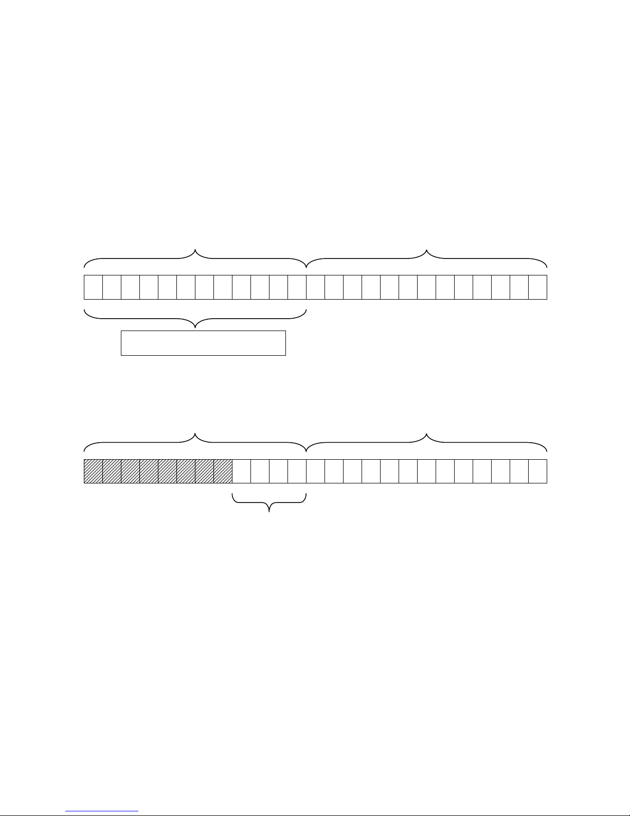
The MR430 controller keeps track of the turns using a 12bit counter. The 12 bit counter is combined with
the 13 bits of single-turn position information for a total of 25 bit position information. That arrangement
allows for up to 4096 turns with a resolution of 13 bits is a maximum position range of 33,554,432. Most
real world applications do not require this kind of measurement range. Therefore the user may want to
limit the number of turns that the sensor keeps track of. The size of the turn counter is controlled by the
user programmable ‘Turn Counter” variable. This number defines how many bits deep the turn counter is
counting until it rolls over back to zero. Please note there are no negative position numbers, all position
number are positive.
Example:
The application needs to measure a position over 12.4 turns. The next binary number is at 16 and therefore
the turn counter should be programmed to count to at least 16 turns. For this to take effect set the turn
counter variable to 4, because 2
4
equals 16. Only the first 4 bits of the turn counter are now activated.
12 11 10 9 8 7 6 5 4 3 2 1 0 24 23 22 21 20 19 18 17 16 15 14 13
13 bit single turn position
12 bit turn counter
2^n counter length selector
13 bit single turn position
12 bit turn counter
4 bits
12 11 10 9 8 7 6 5 4 3 2 1 0 24 23 22 21 20 19 18 17 16 15 14 13
Page 17
MICRONOR INC.
MR430 Fiber Optic Position Sensor System
Page 17 of 50
3.9 Multi-Turn Operation
The MR430 controller accurately counts each turn while the system is powered and the remote sensor is
connected. Under these conditions multi-turn operation is possible.
If remote sensor is disconnected and the sensor position is moved past the zero point, then the turn
counter is no longer synchronized with the actual position. Similarly, if the power to the controller is lost,
then the sensor can no longer keep track of turns.
However, for a quasi multi-turn operation, the MR430 saves the last position, including the turns count,
just as the electrical power is removed from the unit. Often the application is such that when power is lost,
no further movement of the sensor is possible. Under these circumstances, the user may elect to have the
MR430 controller restore the turns upon power-on. To safeguard against erroneous position restoration,
the MR430 controller compares the new start-up single-turn position with the position saved at power
down. If that comparison falls within a user defined range then the turn counter is restored. Together with
the absolute single-turn position the actual multi-turn absolute position is retained in case of a power
outage.
Note
: User must decide if a quasi-Multi-Turn operation is feasible and appropriate.
3.10 Battery Backup for Multi-Turn Operation
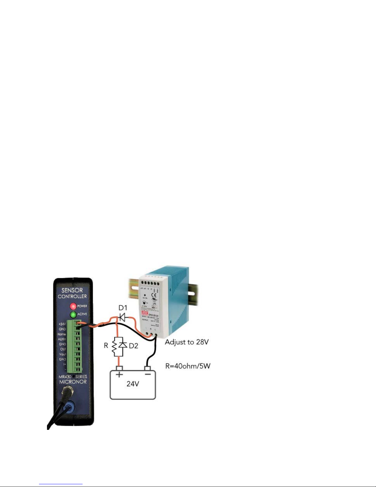
The quasi multi-turn operation as described in the previous section is not fail-safe. A better method is to
use a Battery backup and keep the unit powered up even over prolonged power outages. The low power
consumption of only 60mA makes this feasible.
Figure 10. Suggested Battery Backup Circuit
Page 18
MICRONOR INC.
MR430 Fiber Optic Position Sensor System
Page 18 of 50
3.11 SSI Interface
Figure 11. SSI Interface Connector – J3 (10 pin).
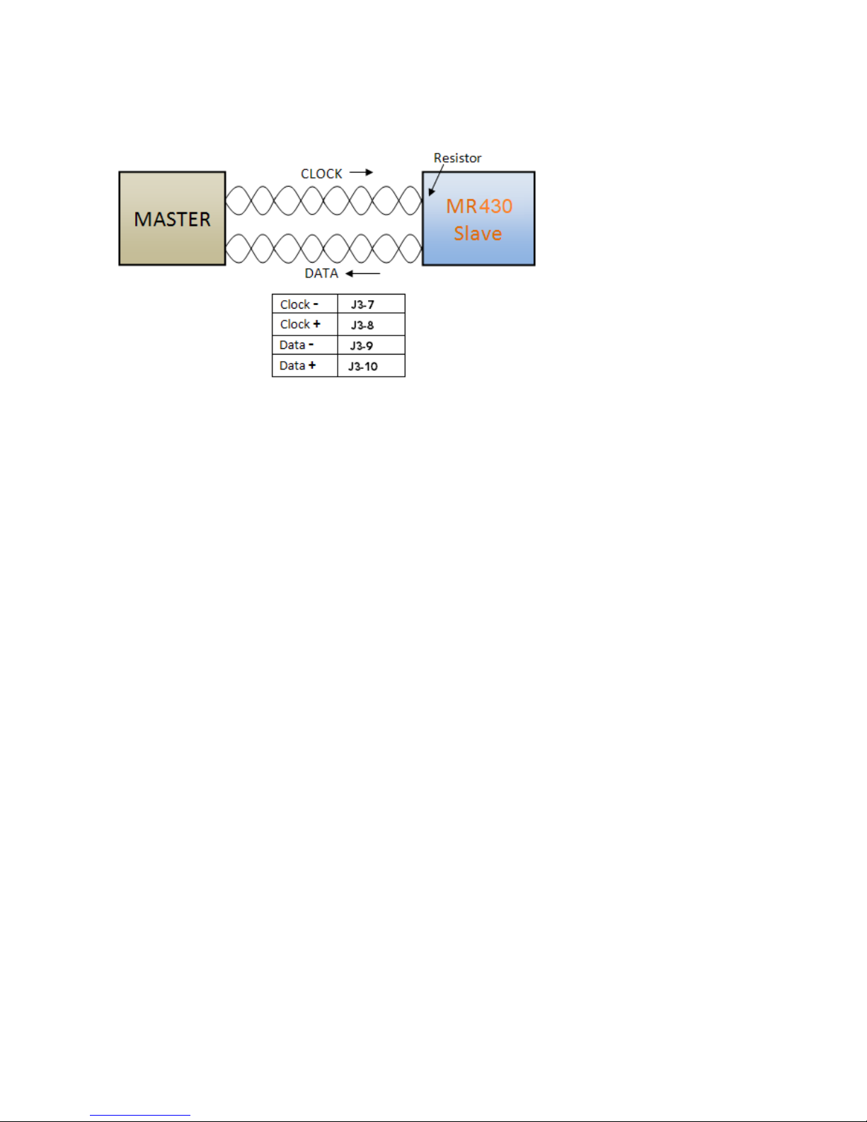
The SSI interface is configured as Slave and the Master must supply the clock. The clock maybe in the
range from 25kHz to 250kHz. The user should also set the MR430 with the appropriate clock rate. This will
allow the MR430 to provide correct timing for repeat read' mode on the SSI bus. If not sure how to set the
SSI baud rate leave it at the lowest setting of 25k baud, this setting will work fine in most applications.
Reading position packets at higher than 4 kHz is not recommended as the update rate of the MR430 is
1.2kHz. Reading at higher intervals will not add more information.
Termination Resistor
For long link length and high clock rate it may be necessary to terminate the Clock line at the MR430 in
order to avoid reflective signal interference. The user must install that resistor external to the MR430. (For
OEM customers please consult MICRONOR as this resistor may be added inside the controller)
Page 19
MICRONOR INC.
MR430 Fiber Optic Position Sensor System
Page 19 of 50
SSI Single Transmission
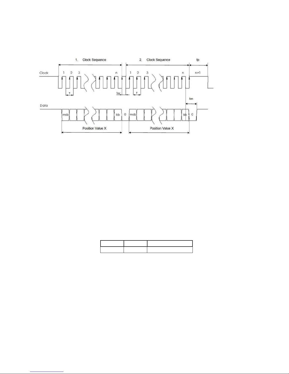
The diagram in below illustrates a single data transmission using SSI protocol:
Figure 12. SSI Single Transmission Timing
The SSI is initially in the idle mode, where both the data and clock line are high. The transmission mode is
evoked when the master initiates a train of clock pulses. Once, the slave receives the beginning of the
clock signal (1), it automatically freezes its current data. With the first rising edge (2) of the clock sequence,
the MSB of the sensor’s value is transmitted and with consequent rising edges, the bits are sequentially
transmitted to the output. After the transmission of complete data word (3) (i.e. LSB is transmitted), and
an additional rising edge of the clock sets the clock line to go HIGH. The data line is set to low and remains
there for a period of time, tm, to recognize the transfer timeout. If a clock signal (data-output request) is
received within the time, tm, the same data as before will be transmitted again (multiple transmission).
The slave starts updating its value and the data line is set to HIGH (idle mode), if there are no clock pulses
within time, tm. This marks the end of single transmission of the data word. Once the slave receives a clock
signal at a time, tp ≥ tm, then the updated position value is frozen and the transmission of the value begins
as described earlier.
To set this timeout, use ZapView® software and select page: ‘SSI Interface”
MODBUS commands
:
Address
Register
Description
0x138
0x139
Baud Rate SSI
Page 20
MICRONOR INC.
MR430 Fiber Optic Position Sensor System
Page 20 of 50
3.12 Voltage Output
The analog output voltage is derived from the position signal and maybe freely scaled by the user. There
are four distinct modes:
Mode 0: OFF, voltage is always 0
Mode 1: Single-turn 0V to +10V
Mode 2: Scalable 0V to +10V
Mode 3: Scalable -10V to +10V
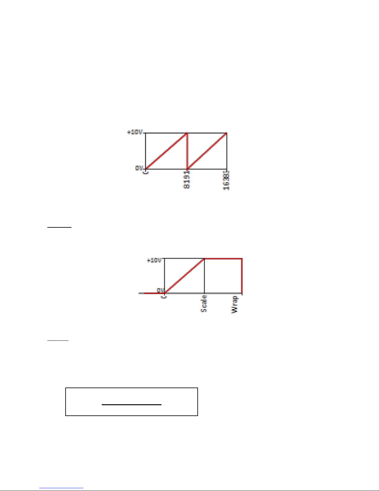
Figure 13. Mode 1 Voltage Output
MODE 1 automatically sets the Scale to 8192. It outputs 0V when position is 0 and +10V when
position is 8191. Output wraps around back to 0V when one turn completes. This wrap around
occurs regardless of the Turn Mask setting.
Figure 14. Mode 2 Voltage Output
MODE 2 lets the user program the output voltage based on a scale value. The output is 0 when the position
is 0 and will reach +10V when the position reaches the scale value. The full 25-bit range is available for
scaling.
When setting this mode up the user should also take into account what should happen when the position
reaches maximum or minimum values. The MR430 system determines the wrap-around point based on
the available position range, which is based on the turn mask setting n. The Count
max
is then 2n
The wrap point P
w
is determined based on the formula above. Essentially, it is the midpoint between the
unused range.
P
w
=
(Count
max
- Scale)
+ Scale
2
Page 21
MICRONOR INC.
MR430 Fiber Optic Position Sensor System
Page 21 of 50
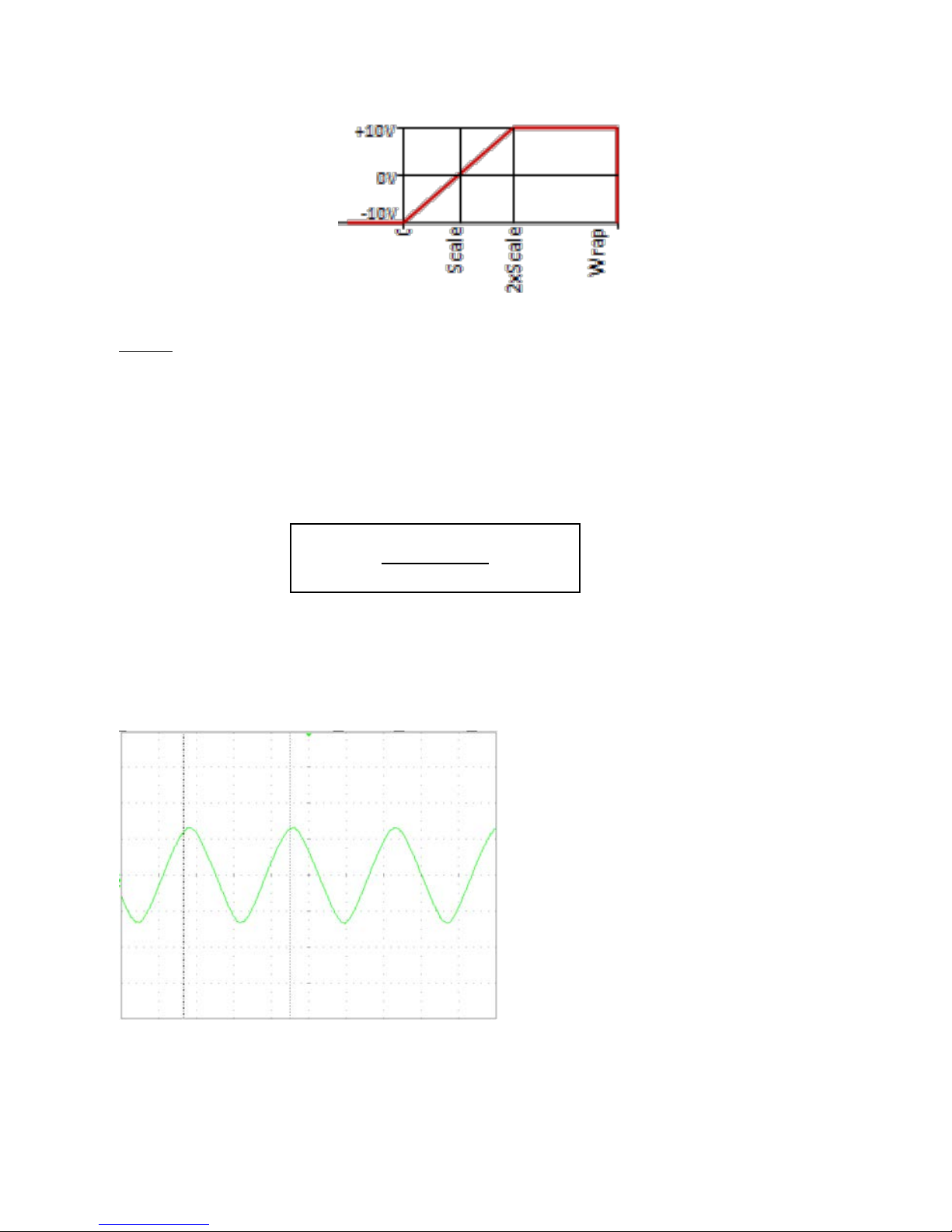
Figure 15. Mode 3 Voltage Output
MODE 3 is very similar to mode 2 but it makes use of the negative output voltage capability of the MR430.
The output voltage follows the position output with 0 position being -10V and when the Scale value is
reached the output is 0V and with position twice the scale value the output is +10V. Mode 3 is ideal when
the voltage should swing positive or negative around a predetermined home position. In that case the
Reset Value of the MR430 should be set to the same value as the scale. When the sensor is in the home
position, it is then equal to the scale value and the voltage output will be 0V. When the sensor turns CCW,
the voltage will start going negative, and, vice versa, when the sensor turns CW the voltage will go positive.
As in mode 2 the system also determines a wraparound point based on the turn counter setting.
The Wrap point Pw is in the middle of the unused range of the senor. The maximum position range is
determined by the Turn Counter setting.
Output Frequency
The voltage output follows the position in real time with a delay of approximately 800us from when the
actual position was reached. The update rate of the D/A converter is 850us.
V: 2V/DIV
H: 50ms/DIV
Analog Output while input shaft is being
oscillated with an amplitude of ±45° at a
frequency of 7Hz.
Ω = 44.3r/s
Figure 16. Analog Output With An Oscillating Shaft Input
P
w
=
Count
max
+ Scale
2
Page 22
MICRONOR INC.
MR430 Fiber Optic Position Sensor System
Page 22 of 50
In ZapView®, select page: ‘
Voltage Output
”
MODBUS commands:
3.13 Isolated Current Output (4-20mA)
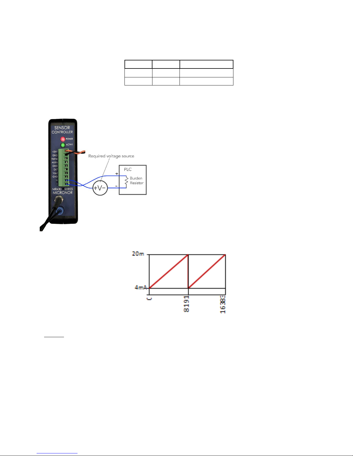
The isolated current output is derived from the position signal
and may be freely scaled by the user. Since the output is
isolated from the rest of the circuitry, it must be loop
powered:
There are three selectable output modes:
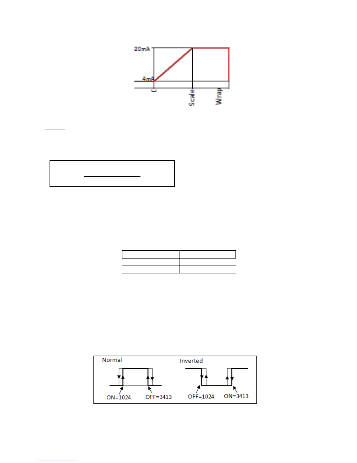
Mode 0: OFF, current is less then 300uA
Mode 1: Single-turn 4mA to 20mA
Mode 2: Scalable 4mA to 20mA
Figure 17. Isolated 4-20mA Connection
Figure 18. Mode 1 Current Output
MODE 1 automatically sets the Scale to 8192. It outputs 4mA when position is 0 and 20mA when position
is 8191. Output wraps around back to 4mA when position changes from 8191 to 0 at the completion of
one turn. This wrap around occurs regardless of the Turn Mask setting.
Address
Register
Description
0x200
0x201
Voltage Mode
0x201
0x202
Voltage Scale
Page 23
MICRONOR INC.
MR430 Fiber Optic Position Sensor System
Page 23 of 50
Figure 19. Mode 2 Current Output
MODE 2 The user programmable scale defines the position where 20mA output current is reached. The
full 25-bit range is available for scaling. When setting this mode, the user should also take into account
what should happen when the position reaches maximum or minimum values. The wrap-around point is
based on the available position range, which is based on the turn mask setting n. The Count
max
is then 2n
The wrap point P
w
is determined based on the formula above. It is the midpoint between the un-used
range.
In ZapView®, select page: ‘
Current Output
”
MODBUS commands:
Address
Register
Description
0x204
0x205
Current Mode
0x205
0x206
Current Scale
3.14 Digital Set Point
There is one user programmable digital set point. The set point, once programmed, may be used as limit
switches. Each output can drive a load of 10mA with 24V output.
The full multi-turn range of 25 bits is available for the set-point limits. The switching point has a fixed
defined hysteresis of 5 counts (~0.22⁰). This hysteresis prevents undesired chatter on the output.
P
w
=
(Count
max
- Scale)
+ Scale
2
Page 24

MICRONOR INC.
MR430 Fiber Optic Position Sensor System
Page 24 of 50
To program, simply define the point in position counts where the output should turn ON (Set_Point_ON)
and then define the point where the output should turn OFF again.
Should the output be inverted; reverse the position points of the two entries and the output will switch at
the same position but with the reversed sign.
In ZapView®, select page ‘Set Points”
MODBUS commands:
Address
Register
Description
0x230
0x231
Set Point 1 On
0x232
0x233
Set Point 1 Off
Page 25

MICRONOR INC.
MR430 Fiber Optic Position Sensor System
Page 25 of 50
4. Serial Communication – Modbus
Integration with a PLC or other host computer within an automation system is via the Modbus compatible
serial interface. Obviously the main purpose is to query the MR430 controller for position information
which is accomplished by reading Register 0x001. In most cases, it is recommended to also include the
status information registers 0x000 with the position register 0x001 for the same read request.
In addition to the position register the MR430 provides a host of auxiliary functions and parameter settings
that the user may choose to utilize. All the functions and parameter settings maybe programmed by the
PLC during system initialization. An alternate way is to pre-configure the MR430 using the MICRONOR
provided ZapView® software and permanently store all the parameters in the EEPROM. Specifically, an
individual configuration of the MR430 controller is required when a specific Modbus address need to be
preset before connecting the controller to the Modbus.
To access these functions and to familiarize yourself with the functionality of the MR430 controller we
recommend to use ZapView® software, which is supplied with the unit. To run ZapView®, you must have
a Personal Computer available with a USB interface. If a USB interface is not available then a serial interface
plus the Micronor RS232-to-RS422/RS485 converter cable model MRS232-1 (must be purchased
separately) maybe used.
4.1 USB-Serial Emulator
The MR430, being Modbus compatible, must communicate via a serial interface, thus the USB interface
utilizes the Future Technology Devices International (FTDI) interface chip www.ftdichip.com
. This chip
communicates via USB, but within the PC emulates a serial COM port. When ZapView® is installed, the
appropriate FTDI driver is installed on the PC. The conversion from USB to Serial is essential to keeping
the communications protocol Modbus compatible.
Even when communicating via USB the MR430 controller uses the actual baud rate and bus address
settings. The baud rate of the PC’s COMx port must therefore be set to match the baud rate of the MR430
controller.
DEFAULTS
The default bus address of the MR430 controller is 235.
The default and recommended baud rate is 57,600 baud, 8bits, 1 Stop, No Parity
Page 26

MICRONOR INC.
MR430 Fiber Optic Position Sensor System
Page 26 of 50
4.2 Serial Interface Specification
• RS-422/RS485 Duplex addressable bus interface
• Baud rate programmable: 9,600 / 19,200 / 38,400 / 57,200 or 11,5200 baud
• 1 Start Bit
• 8 Data Bits
• 1 Stop Bit
• no parity
Factory Standard Modbus Address is set to 235 (Hexadecimal 0xEB)l.
When not using a USB interface, the optional MR232-1 Interface cable may be connected directly to a PC
Computer via standard RS232 and DB9 connector. In that case the maximum baud rate is 57,600. The
MR232-1 Interface cable converts the RS232 signals to the RS485 compatible signals of the MR430.
4.3 Physical Connection for Modbus operation
BUS
Master
Wire
Slave
MR430
Connector -J3
TXD0
RXD0
A
RCV- (6)
TXD1
RXD1
B
RCV+ (5)
RXD1
TXD0
A
TX- (4)
RXD0
TXD1
B
TX+ (3)
GND
GND
GND (1)
Four Wire Configuration:
Two Wire Configuration:
MR430 – J3
1 - GND
2 - +5V
3 - TX+
4 - TX5 - RCV+
6 - RCV-
Bus - Master
GND
RXD1
RXD0
TXD1
TXD0
MR430 – J3
1 - GND
2 - +5V
3 - TX+
4 - TX5 - RCV+
6 - RCV-
Bus - Master
GND
RXTXD1
RXTXD0
Page 27

MICRONOR INC.
MR430 Fiber Optic Position Sensor System
Page 27 of 50
4.4 Serial Bus Termination Resistor
The Serial Interface of the RS485 interface internally “open”, it does not have a termination resistor inside.
The user must add this resistor externally if so required.
Since this is a fiber optic sensing system, it is expected that the Controller is always located nearby or
within the same control closet where the position signal is required. Long electrical link lengths should
thus be avoided.
4.5 MODBUS Communications Protocol
The communications protocol follows the Modbus RTU (binary) protocol. A number of commands allow
for configuring the operational parameters of the MR430 while other commands are specifically meant for
diagnostics used during setup, maintenance and troubleshooting. The status and position readout
registers are intentionally arranged in sequence for a quick readout while system is in operation mode.
The format for the commands and responses in general follow the MODBUS RTU specification, with the
exception that not all registers maybe combined within one readout sequence. See table below for
allowable register combination.
MODBUS information can be obtained at: www.Modbus.com
What Is ZapView®430 Setup Software?
MICRONOR provides ZapView®, a user friendly setup program free of charge along
with the purchase of the MR430 system. ZapView® runs on Windows 10 and requires
Microsoft .net Framework 4.0 to be on the machine.
Please refer to section x.xx for detailed information.
Unless you plan to connect the MR430 to your own PLC or computer equipment for
real-time data retrieval, there is no need to become familiar with the Communications
protocol described herein.
Framing
Message frames are separated by a silent interval of at least 3.5 character times. If a silent interval of more
than 1.5 character times occurs between two characters of the message frame, the message frame is
considered incomplete and is discarded.
A 16bit LRC/CRC Frame Check follows the message.
Device Address Selection:
The MR430 comes pre-configured with Device address 235
The MR430 always listens to address 235 (Broadcast Address). To re-program the device address, send
desired new address via command FC10 to register 0x104 via the broadcast address (235) and then send
the appropriate “STORE EEPROM” command via FC52 register. Upon executing this procedure, the unit
will listen to the newly assigned Device Address and the Broadcast address 235.
In a bus system do NOT use the Broad cast Address 235.
Page 28

MICRONOR INC.
MR430 Fiber Optic Position Sensor System
Page 28 of 50
In ZapView®, select tab page “System Info” and enter the desired new bus address
and hit <enter> key. When the red “Save to EEPROM” button pops up push this
button and the new address is stored in the MR430 controller.
REGISTER NUMBERS VS. METER ADDRESSES
In this instruction manual all register are referred to by their address i.e. starting at 0.
Some Master devices (e.g., Modicon) require that the desired Register Number and not the Register
Address be entered. The Register Number is 1 higher than the Register Address. For entry to these
devices, add 1 to the Register Address shown in the tables below. The Register Address shown will then
be output from these devices.
FUNCTION FC03 – Read Holding Registers
FUNCTION FC10 – Write Holding Registers
Holding registers FC03 are used for reading the position and all other parameters
These Registers can be written using Function FC10 using identical address offset
Register
Address
Register
Number
Name
#
regs
Range
Description
0x000
0x001
System Status
1
n/a
Returns the system status.
num register = 1 : reads status only
num register = 3 : reads status & position
num register = 4 : reads status & position
& angle
num register = 5 : reads status & position
& angle & amplitude
0x001
0x002
Get Position
2
n/a
Returns position count as a 32 bit integer
0x003
0x004
Get Angle
1
n/a
Returns position angle in 1/100 of degrees
(0..36000)
0x005
0x006
Get Last Position
2
n/a
Returns the very last position when unit was
shut down. Used when determining if the
turn counter restore is feasible.
0x040
0x041
Get Error Counts
24
n/a
Returns 24 registers with the total number
of errors for each error class.
0x100
0x101
Set New Position
2
0..MaxCount
The value is used as the new position
readout. The MR430 automatically
calculates a position offset.
0x102
0x103
Get Position Offset
2
n/a
Position offset used to adjust for desired
position readout.
0x104
0x105
Device Address
1
1 – 254
Sets the MR310 serial address for
commands. Note that the address 4
cannot be used.
A FC06 command to save EEPROM must
be issued following this command.
0x105
0x106
Operating Mode
1
0..3
Used to setting MR430 in calibration, or
troubleshooting mode.
Normal Operating is 0.
Debug mode is 1.
Page 29

MICRONOR INC.
MR430 Fiber Optic Position Sensor System
Page 29 of 50
Pairing Operation is 2.
Do not put unit in any of these modes
without first consulting the user manual. Be
familiar with what these functions before
using.
0x106
0x107
Get Temperature
1
n/a
n/a for model MR430
0x130
0x131
Scan Start
1
1 – 200
Factory use only – do NOT write to it.
Determines the start of the disk code
reading
0x132
0x133
Voltage Offset
1
-128 – 127
Factory use only – do NOT write to it.
Hardware calibration value for voltage
output
0x133
0x134
Voltage Gain Pos
1
-128 – 127
Factory use only – do NOT write to it.
Hardware calibration value for voltage
output
0x134
0x135
Voltage Gain Neg
1
--128 – 127
Factory use only – do NOT write to it.
Hardware calibration value for voltage
output
0x135
0x136
Current Gain
1
-128 – 127
Factory use only – do NOT write to it.
Hardware calibration value for current
output
0x136
0x137
Turn Counter
1
0 - 11
Depth of Turn Counter in binary
increments (2n)
User sets this value depending how far the
turn counter should count until resetting to
0 again
Example: n = 3: Maximum Position readout
is: 8 revolutions with 8192 per revolution.
Therefore maximum position readout will
be 65,536.
0x137
0x138
Resolution of
Readout
1
13 | 14
Sets the internal readout resolution.
13
bit is fully compatible with electrical
encoders.
14 bit provides a resolution of 13950 per
revolution. (not full binary 14-bit resolution)
0x138
0x139
Baud Rate SSI
1
25 – 250
Defines the SSI Baud Rate.
This value should be set by the user and it
should match the clock frequency of the
SSI master reading the position output.
0x139
0x13A
Baud Rate Serial
Communications
1
0 – 3
Sets the Baud Rate for Serial
Communications on the MODBUS.
0 = 9,600
1 = 19,200
2= 38,400
3 = 57,600
4 = 115,200
0x13A
0x13B
Optical Amplitude
Report
1
0 to 1023
Read-Only reports signal strength
Should be in the range of 300 to 600 for
normal operation.
0x13B
0x13C
Pairing Progress
1 Returns the currently executing calibration
step.
Page 30

MICRONOR INC.
MR430 Fiber Optic Position Sensor System
Page 30 of 50
Read Only, only active during the pairing
process.
0x13C
0x13D
Reserved
0x13D
0x13E
Reserved
0x13E
0x13F
SSI_Mode
SPI Mode
1
0..3
0 = Position, 1=Angle in 1/100°
B0 = CKP; B1=CKE
0x13F
0x140
Setpoint Output
1
0..1
Sets or Reset Output (J1-6)
0x140
0x141
Input Port
1
0..7
Reads hardware port status
B0=SW1, B1=Home, B2=Aux Input
0x141
0x142
Sensor Cal. value
1
-20 to +20
This value is automatically set when sensor
pairing. Do not change.
0x142
0x143
Reserved
0x200
0x201
Voltage Mode
1
0 - 3
Defines the output mode for the voltage
output.
0 = OFF no Position Output
1 = Single Turn 0 to 10V
2 = Multi Turn 0 to 10V
3 = Multi Turn -10V to +10V
0x201
0x202
Voltage Scale
2
0 – MaxCount
Establishes the scale used for the voltage
output. Regardless of Voltage Mode
setting 10V refers to the scale value.
When the position count reaches the scale
value the output is 10V.
0x204
0x205
Current Mode
1
0 – 2
Defines the output mode for the current
output.
0 = OFF current is < 300uA.
1 = Single Turn 4 to 20mA
2 = Multi Turn 4 to 20mA
0x205
0x206
Current Scale
2
0 – MaxCount
Establishes the scale used for the isolated
current output. Regardless of current
Mode setting 16mA refers to the scale
value. When position count reaches the
scale value then the output is 16mA plus
4mA bias for a total of 20mA.
0x208
0x209
Reset Mode
1
0 – 1
Defines how the hardware input resets the
internal counter.
0 = Edge Triggered, resets the counter at
the first rising edge
1 = Debounced Trigger when state
changes from 0 to 1 after 60ms debounce
time. (used for switch or relay input)
0x209
0x20A
Preset Value
2
0 - MaxCount
Counter will be preset to this value when
the Zero push button is pressed or when
hardware input is activated. (See Reset
Mode)
0x20B
0x20C
Turn Direction
1
0 - 1
Defines output results based on turning
direction of the sensor
0 = when CW outputs are positive reading.
1 = when CCW then outputs are positive
reading
0x20C
0x20D
Power Up Mode
1
0 – 1
Defines if controller should attempt to
restore the turn counter after power-up.
Page 31

MICRONOR INC.
MR430 Fiber Optic Position Sensor System
Page 31 of 50
0 = do not restore turn counter.
1 = attempt to restore turn counter.
When within the restore range then restore
full position, otherwise indicate an error.
0x230
0x231
Set Point 1 On
2
0 - MaxCount
Lower threshold for digital limit switch
output 1
0x232
0x233
Set Point 1 Off
2
0 - MaxCount
Upper threshold for digital limit switch
output 1
0x234
0x235
Set Point 2 On
2
0 - MaxCount
n/a for MR430
0x236
0x237
Set Point 2 Off
2
0 - MaxCount
n/a for MR430
0x237
0x238
Restore Range
1
0 - 4095
Defines the range within the automatic turn
counter restore will be considered valid.
0x300
0x301
Ref Voltage
1
n/a
Internal Reference voltage of 2.5V
Updated only at Power ON
0x301
0x302
5 Volt Supply
1
n/a
Internal Supply Voltage 5V
Updated only at Power ON
0x302
0x303
12 Volt Supply
1
n/a
Internal Supply Voltage 12V
Updated only at Power ON
0x303
0x304
24V Power Supply
1
n/a
External applied Voltage 24V nominal
Updated only at Power ON
0x304
0x305
n/a 1 n/a
0x305
0x306
n/a n/a 0x306
0x307
n/a n/a
0x307
0x308
n/a n/a
0x330
0x331
DAC 1, Chan 1
1 Internal Digital to Analog Converter Value
Positive Voltage Output
0x331
0x332
DAC 1, Chan 2
1 Internal Digital to Analog Converter Value
Negative Voltage Output
0x332
0x333
DAC 1, Chan 3
1 Internal Digital to Analog Converter Value
CCD Bias voltage
0x333
0x334
DAC 1, Chan 4
1 Internal Digital to Analog Converter Value
Optical source bias Voltage
0x334
0x335
Reserved
0x339
0x33A
Optical Pulse Time
1
0..65
Factory use only!
Determines the Optical Pulse Strength for
Sensor interrogation.
0x400
0x401
Device Name
4
n/a
Returns the ASCII string equivalent as
device name (MR430)
0x404
0x405
Version
4
n/a
Returns the ASCII string equivalent of the
software version form MM.mm.bb
0x408
0x409
Serial Number
2
n/a
Returns the serial number of the device.
Note:
MaxCount = 2^25-1 => 33,554,431
Page 32

MICRONOR INC.
MR430 Fiber Optic Position Sensor System
Page 32 of 50
FUNCTION FC05 – Write Single Coil
Single Coil commands are used to trigger an action.
Register
Address
Register
Number
Name
Description
0x001
0x002
Device Reset
Same as a Power OFF and Power ON cycle.
0x002
0x003
Save to EEPROM
Save current parameters to EEPROM.
A time delay of approximately 20ms should be allowed
before sending any other command.
0x003
0x003
Restore
From EEPROM
Restore all configuration parameters from EEPROM.
Same as a Power Up.
0x004
0x004
Restore
Factory Default
Restores Factory Defaults.
The MR430 stores a factory default for each user parameter.
These values maybe restored using this command.
Factory calibration values and pairing data are not affected.
0x004
0x005
Clear Status
Clears the status register. If another error is pending then
the status register will reflect that new value in queue.
0x005
0x006
Clear Error Count
Table
Resets error table counters to 0.
Same as in power up.
MODBUS Message Format
The following is a brief overview of the detailed byte by byte messaging of the Modbus protocol. Please
consult the Modbus standards for detailed information.
DA
= Device Address
DD
= Data to read
CRCL
= CRC Byte low
FC
= Function Code
WW
= Data to write
CRCH
= CRC byte high
RA
= Register Address
SF
= Sub Function
DD*
= Number of bytes
requested or being sent
NR
= Number to Read
EC
= Error Code
NB
= Number of bytes
FC
Action
Sync
3.5b
Byte Number
1 2 3 4 5 6 7 8 9
10
11
01
01
request
response
pause
DA
DA
FC
FC
RA
NR
03
03
request
response
pause
DA
DA
FC
FC
RA
NB
RA
DD*
NR
DD*
NR
CRL
CRL
CRH
CRH
04
04
request
response
pause
DA
DA
FC
FC
RA
NR
05
05
request
response
pause
DA
DA
FC
FC
RA
RA
08
08
request
response
pause
DA
DA
FC
FC
SF
SF
23
23
request
response
pause
DA
DA
FC
FC
RA
NR
RA
DA
DA
FC
FC
Page 33

MICRONOR INC.
MR430 Fiber Optic Position Sensor System
Page 33 of 50
5. MR430 - Error Handling and Troubleshooting
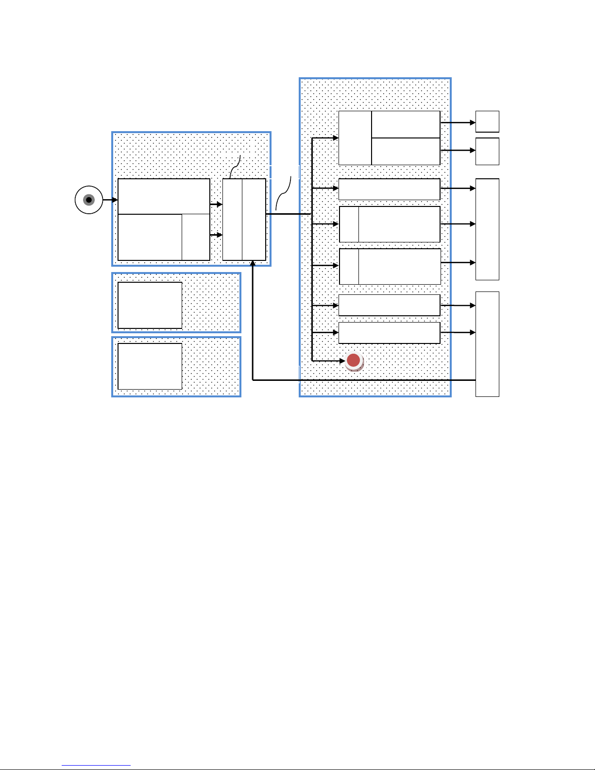
5.1 Explanation of Status and Error Handling
The MR430 incorporates a sophisticated integrity monitoring, error and failure reporting system. There
are four Error Groups:
1. EEPROM
At start-up the EEPROM checksum and EEPROM data integrity are checked.
2. Power Supply Voltages
At start-up the applied power supply voltage (24V) and internal voltages are checked. If they fall
outside the required value, errors are logged and reported. These voltages are evaluated once at
system power-up. Subsequent voltage changes will not be evaluated.
3. Sensor Read Error
• Low optical power
• Position read error
• Restore Value out of Range
4. Communication Errors
Communication errors are flagged by the underlying Modbus drivers. However, Modbus standard
does not specify a data integrity test. This is where the MR430 allows the user to query the Status
byte after each transmission to verify if the provided data was within the appropriate range etc.
5.2 Explanation of Status and Error Indication
When an error occurs the System Status Word is set with the associated Error Code (Register 0x00). When
more than one error at the time occurs then the error code is stacked up in order of its priority.
Each Error has an associated error counter. The user may request all error registers for examination through
a request to Register 0x040. MODBUS Function Register 0x40, Reads all 24 Error Registers Sequentially
Table 1 lists all the status and error report possibilities.
Status
E-Stack 1
E-Stack 2
E-Stack 3
Counter 1
Counter 2
Counter 24
Counter 3
Reg 0x00
Reg 0x040
Priority
Page 34
MICRONOR INC.
MR430 Fiber Optic Position Sensor System
Page 34 of 50
All errors get logged but may not necessarily provide visual indication. The user should take necessary
action based on the severity level of the reported status/error.
3
= System will no longer work without a remedy.
2
= Important, problem should be fixed but system may still be partially operational
1
= Benign, system keeps on working fine
After examination the user may clear the Error Indication by issuing the Function Call FC5 to coil number
5. This will clear the indicated error in the Status byte. If there are more errors stacked up, then the next
highest priority will be displayed.
While there is an error Indication The Zero push button will also clear a pending error indication. The user
must be careful to only push the button once and wait and check if the error indication. Because once the
error is cleared the button will assume it’s normal function as a Zero Point switch.
Some errors are cleared as soon as normal operation is established. For instance when the sensor is
disconnected or a high loss in the optical connection occurs then an error is reported and the PWR LED
will blink. However, when the optical connection is re-established then the error will clear itself without
user interaction.
Some errors are not sufficient cause of a problem and therefore they are logged and indicated by a short
blink on the PWR LED and then will clear themselves. For instance, if the 24V power supply deviates by
Absolute
Single turn 13bit
Turn
Mask
Voltage
Scaling
Mode
Current Scaling
Mode
RESET
Set-Point 1
Set-Point 2
SSI
pos_fu
ll
pos_rp
rt
J3 J2 J1
ZERO
Indicator
RS422/485
USB
Serial
Interface
US
B
Turn
Counter
12bit
Zero Offset
Full Position
EEPROM
Power
Supply
Group 4
Group 3
Group 1
Group 2
Error Groups
Page 35

MICRONOR INC.
MR430 Fiber Optic Position Sensor System
Page 35 of 50
more, than ±10% such an error is indicated but since the MR430 works flawlessly in the range of 15V to
30V there is no cause for further error indication.
Table 1. Table of Error Codes
Hardware Related Status Indication
EEPROM
#
Description
S
Remedy
How
Cleared
Announced
257
EEPROM INIT
EEprom is not initialized not
initialized. This occurs only on first
factory power up of new system or
when a badly corrupt EEPROM is
detected
3
Firmware automatically re-
initializes the EEPROM.
User must remove Power
and apply power again
Restore factory values.
All parameters are lost.
Recycle
Power
Blink 5x
+
code
258
EEPROM Checksum
checksum failure both banks
3
Both data banks indicate a
bad checksum.
User should read all
parameters and verify
proper settings and then
save parameters again
using Micronor Zappy
software.
software
or
recycle
Power
Blink 5x
+
code
259
EEPROM Checksum Low Bank
checksum failure low bank
1
One set of data in
EEPROM shows a bad
checksum. Firmware
automatically corrects the
error.
n/a n/a
260
EEPROM Checksum High Bank
checksum failure low bank
1
One set of data in
EEPROM shows a bad
checksum. Firmware
automatically
corrects the
error.
n/a n/a
261
EEPROM Bad Value
One or more parameter values are
out of range in both data banks.
3
User should use Zappy to
read and examine the data
and restore the corrupted
value.
Timed
Clear
Blink 5x
+
code
Voltages
#
Description
S
Remedy
How Cleared
Announced
513
Bad Hardware
No Clock Signal from CPLD
Bad I2C Bus on internal
components
3
Recycle Power
If persist repair
next startup
blink 5x
514
BAD Firmware
Firmware is corrupted
3
Recycle Power
If persist repair
next startup
blink 5x
515
Voltage Reference
Internal reference voltage is out of
tolerance
3
Recycle Power
If persist repair
next startup
Blink 4x
+
Code
516
Voltage 5V
Internal 5V out of tolerance
3
Recycle Power
If persist repair
next startup
self-clear
when restored
Blink 4x
+
Code
Page 36

MICRONOR INC.
MR430 Fiber Optic Position Sensor System
Page 36 of 50
517
Voltage 12V
Internal 12V out of tolerance
2
Recycle Power
If persist repair
Timed self-
clear or selfclear when
restored
Blink 4x
+
Code
518
Voltage 24V Low
User applied 24V is of +/-10%
tolerance
(measured on AN4)
1
Apply proper voltage.
It’s ok to operate unit
anywhere from +15V
to +30V
self-clear
Blink 2x
+
Code
519
Voltage 24V too Low
User applied 24V input less then
14V
3
Apply proper voltage.
Blink 2x
+
code
Position Sensor Failures
#
Description
S
Remedy
How Cleared
Announced
769
Sensor Not Paired
System detected that the sensor is
not paired to the Controller.
For best performance a sensor
should be paired to the controller.
This test is performed at power
ON.
2
User should use ZAPPY
software and follow
the procedure ‘Pairing
Sensor”
Push-button
will clear this
error.
FC5 #5
Blink 3x
+
code
770
Sensor Disconnect
Detect low optical power
3
Check Fiber Optic
connection to the
sensor. Initiate a new
Sensor pairing.
self-clear
when restored.
Blink 3x
+
code
771
Sensor Read Error
Single Read Error. The sensor
makes a position measurement
every 850µs. This error indicates
that an invalid position reading
has occurred. (binary code on the
disk allows for error checking).
1
This error may occur
when the encoder is
rotated faster than
2500rpm; insufficient
optical power; sensor
is not paired with
controller.
self-clear
examine error
counter for a
history of this
error.
None
772
Sensor 65000
Read Error >1 in 65000
System keeps an
statistical track
how often this error occurs. See
appendix A
2
If this occurs the
installation should be
checked for optical
connection. Or
perhaps the system
rotates the sensor too
fast.
self-clear
examine error
counter for a
history of this
error.
Blink 3x
once
773
Sensor 1024
Read Error >1 in 1024
System keeps an statistical track
how often this error occurs. See
appendix A
3
If this occurs the
installation should be
checked for optical
connection. Or
perhaps the system
rotates the sensor too
fast.
self-clear
examine error
counter for a
history of this
error.
Blink 3x
Until cleared
774
Sensor Turn Restore
The position of the sensor at last
power down differs from the
position at power-ON.
1
This indication is
important when using
the sensor as a multi-
turn position sensor.
The user should now
Clear by FC5
coil 5
Blink 3x
Page 37

MICRONOR INC.
MR430 Fiber Optic Position Sensor System
Page 37 of 50
The sensor has moved
outside
the ‘Restore’
value while power was off.
determine if the stored
position can be
restored or if the
system needs to be
homed. See also
Restore range
Command R
Communication Failures
# Description
S
Remedy
How Cleared
Announced
1025
CMD Unknown Function
A non-valid or nonimplemented Modbus function
was sent to the controller
1
Check your software
for correct function
calls.
self-clear
after one blink
Blink 1x
once
1026
CMD Unknown Register
A non-implemented register
address was addressed
1
Check your software
for correct register
addressing.
See user manual with
address table.
self-clear
after one blink
Blink 1x
once
1027
CMD Wrong Register Count
The register count in your
command did not match the
length of requested register.
1
Check your software
for correct register
addressing.
See user manual with
address table.
Note:
This controller
does not allow to read
across multiple
registers.
self-clear
after one blink
Blink 1x
once
1028
CMD Wrong Device Addr.
The device address sent was
not matching the address of this
unit.
1
The MR430 controller
has on fixed address
at 235. If you are not
sure what the address
is talk to the unit at
235 and reset your
desired bus address.
self-clear
after one blink
Blink 1x
once
1029
CMD Wrong Value
The data value was outside the
permissible range for this
parameter.
1
Consult the user
instruction for the
permissible
parameter values
allowed in each
register.
self-clear
after one blink
Blink 1x
once
1030
CMD Checksum
Modbus Packet Checksum was
invalid.
1
Resend the packet.
self-clear
after one blink
Blink 1x
once
Page 38

MICRONOR INC.
MR430 Fiber Optic Position Sensor System
Page 38 of 50
5.3 Reading the Error Counters
The entire packet of all 24 error counters may be read by issuing MODBUS command to Register 0x040
with a register count of 24. The sequence of registers is according to the error number in Table 1 in
ascending order.
Each register is a 16-bit word. If the most significant bit is set to a logical one, this indicates that there is
an active error residing in the Status stack.
The remaining 15 bits indicate the number of errors that occurred since power was applied to the unit.
The user may clear all error counters by issuing Function Call FC5 coil #6.
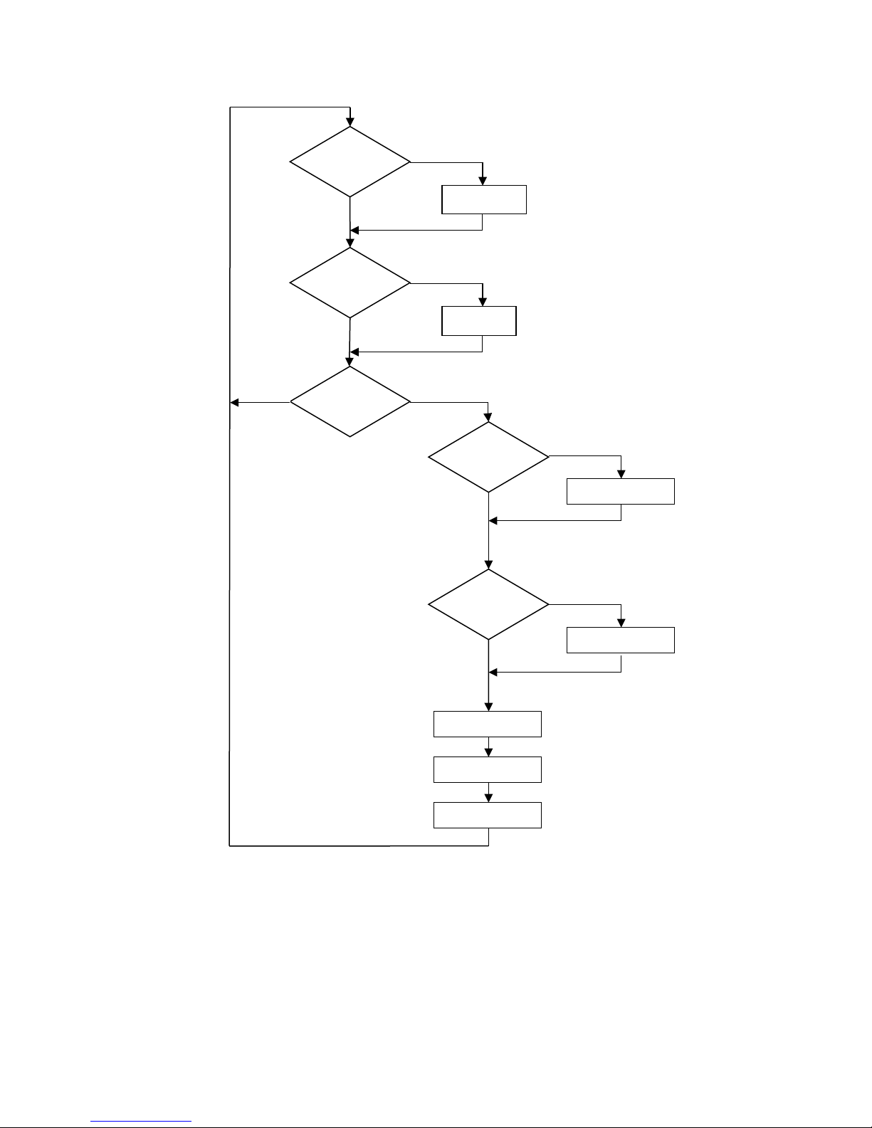
5.4 About Statistical Read Error Determination
The errors Sensor 1024 and Sensor 65000 are error rates that are measured by error occurrences within a
time period. If more than one error occurs within the specified time period, then an error is logged. The
time period is the number of samples times 850uS. 1024 x 850us = .87 seconds
65000 x 850us = 55 seconds.
Note: T1 and T2 are sample counters
The following algorithm is used to detect the errors:
Page 39
MICRONOR INC.
MR430 Fiber Optic Position Sensor System
Page 39 of 50
N
T1 <
1024
T1 <
1024
Inc T1
Inc T2
NewE
rror
Log Error
(1024)
Clear New
Error
T2<5
6000
Log Error
(56000)
Reset T1
Reset T2
N
N
N
T2 <
56k
N
Y
Y
Y
Y
Page 40

MICRONOR INC.
MR430 Fiber Optic Position Sensor System
Page 40 of 50
5.5 Warranty Information
Warranty
MICRONOR INC. warrants this product to be free from defects in material and workmanship for a period
of 1 (one) year from date of shipment. During the warranty period we will, at our option, either repair or
replace any product that proves to be defective.
To exercise this warranty, write or call your local MICRONOR INC. representative, or contact MICRONOR
INC. headquarters. You will be given prompt assistance and return instructions. Send the instrument,
transportation prepaid, to the indicated service facility. Repairs will be made and the instrument returned
transportation prepaid. Repaired products are warranted for the balance of the original warranty period,
or at least 90 days.
Limitations of Warranty
This warranty does not apply to defects resulting from unauthorized modification or misuse of any product
or part. This warranty also does not apply to Fiber Optic Connector interfaces, fuses or AC line cords. This
warranty is in lieu of all other warranties, expressed or implied, including any implied warranty of
merchantability of fitness for a particular use. MICRONOR INC. shall not be liable for any indirect, special
or consequent damages.
Contact Information:
Micronor Inc. Tel +1-805-389-6600
900 Calle Plano, Suite K Fax +1-805-389-6605
Camarillo, CA 93012 Email [email protected]
USA URL www.micronor.com
For Europe:
Micronor AG Tel +41-44-843-4020
Pumpwerkstrasse 32 Fax +41-44-843-4039
CH-8015 Regensdorf Email [email protected]
SWITZERLAND URL www.micronor.ch
Page 41

MICRONOR INC.
MR430 Fiber Optic Position Sensor System
Page 41 of 50
6. Specifications
6.1 MR430 Controller Specification
Position Measurement
Single Turn Resolution
13 bits, 8192 counts, 0.044°
Turn Counter
Up to 12 bits (4096 turns)
Electrical Interfaces
SSI
Up to 25 bits (13 bits ST + 12 bits Multi-Turn), Programmable
baudrate 25 kHz – 250 kHz
RS485/Modbus RTU
57,600 Baud default.
USB
USB, Disables Modbus interface when used, Assigned Virtual Com
Port
Current Output (I+/I-)
Isolated 4-20 mA (270V isolation maximum), Output scalable by user
Voltage Output (Vout)
-10 V to +10 V Load, Output scalable by user, Accuracy = ±0.25%
Full Scale
Digital Output (OUT)
0-5V maximum, 5mA load, Programmable Set Point
Digital Input
+24V logic
Power Supply
+18 VDC to +28 VDC, 65 mA max. at 24 VDC
NOTE: Power supply shall be current limited to 200mA.
Interface Update Rate
Angular Speed
230 radians/second or 2200 RPM for accurate position reporting
Update Rate
1.17 kHz (850 µs)
Reporting Delay
SSI: Maximum 800 µs (time from actual position to SSI output)
Analog Outputs: Maximum 1.0 ms
Optical Interface
Class 1 Laser Safety
Interface
Duplex, M-POF Assembly
System Loss Budget
23dB at 645nm
Maximum Optical Link Length
Up to 30 m (~100 ft) with MR431 Sensor
Typical 2-way loss is 0.75dB/m
Explosive Atmospheres
Inherently Safe, Optical Radiation
EX Classification
Controller shall be installed in non-hazardous location only
IEC Ex
EPL Mb/Gb/Gc/Db/Dc
Environmental Performance
Temperature/Humidity
Operating : -5° to +55°C (+23°F to +131°F)
Storage: -25° to +65°C (-13F to +149°F)
25% to 95% RH (non-condensing)
Ingress Protection
IP40
Physical Attributes
Housing Dimensions
114 W x 89 D x 32 mm H, includes 35mm DIN rail mount
Unit Weight
230 g (8.1 oz)
Specifications subject to change without notice
Page 42

MICRONOR INC.
MR430 Fiber Optic Position Sensor System
Page 42 of 50
6.2 MR431 Sensor Specifications
Measurement Parameters
Measurement Range
0° to 360° (continuous)
Resolution
13 bits (8192), 0.044°
Accuracy
0.5° max, 0.3° typical
Repeatability
±0.175°
Maximum RPM
500 RPM continuous, 2,200 RPM intermittent
Note: 2200 RPM for <2 seconds duration, in stop motion allowed
Mechanical Performance
Starting Torque
0.1 N*m
Max Shaft Load
500g at 5mm distance
Optical Interface
Optical Interface
Duplex, POF and M-POF
Link Length
Up to 30 meters (100 ft) with MR430 Controller
Explosive Atmosphere
Inherently Safe, Simple Mechanical Device
EX Classification
Inherently safe, simple mechanical device when used with MR430-1
Controller
IEC Ex
EPL Mb/Gb/Gc/Db/Dc
MR Attributes
ACR Guidance Document for Safe MR Practices
MRI Usage Zones
MR431 Sensor and MR439 Cabling is designed for safe use in Zones
I-IV
Materials
MRI Safe, Non-Metallic, Shaft/Body: Acetal
Environmental Performance
Sensor Temperature
Operating: -5°C to +55°C (+23°F to +131°F),
Storage: -40°C to +80°C (-40°F to +176°F)
Cable Temperature
Operation: -40°C to +60°C (-40°F to +140°F),
Storage: -40°C to +60°C (-40°F to +140°F),
Humidity
0%-95% RH (non-condensing)
Ingress Protection
IP65
Physical Attributes
Housing Dimension
Ø 25mm x 26mm x Ø6mm Shaft
Unit Weight
15g (0.53 oz.)
Specifications subject to change without notice
Page 43
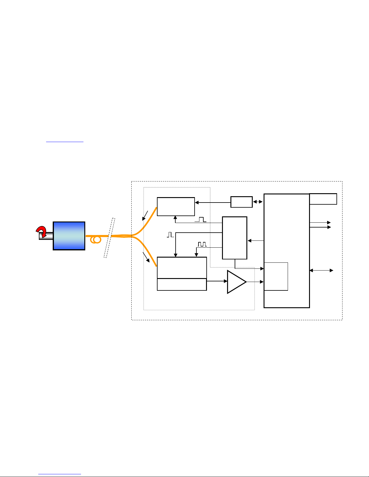
MICRONOR INC.
MR430 Fiber Optic Position Sensor System
Page 43 of 50
7. ZapView® -MR480 Software
Micronor provides ZapView®-MR480 for configuring MR430 Controller Module. ZapView® is used to preprogram MR430 parameters associated with the various Auxiliary Functions, such as programming the
scale of the analog outputs, or it can be simply used to verify the proper operation of the position sensor
system. The software also includes diagnostic and troubleshooting functions.
ZapView®-MR480 runs on Windows 10 with .NET Framework 4.0 installed.
For information on installing and using the software, please consult the separate ZapView®-MR480
Instruction Manual supplied with the MR430 Controller - or download the current version from the
Micronor.com
website.
8. MR430 Theory of Operation
Figure 20. Block Diagram of the Fiber Optic Position Sensor System
The functional block diagram shows the two main components The Sensor is connected by a duplex fiber
optic cable. The Transmit fiber guides an optical pulse from a red LED to the position sensor. A second
Receive fiber returns the light with the embedded position information in the form of a specific unique
light pattern impressed on to the imaging fiber.
The optical image of the returned light pattern is unique to any given position of the sensor. This light
pattern is imaged to a linear CCD sensor which converts the optical pattern into an electrical
representation of the position pattern. The firmware algorithm extracts the position information, converts
the position into digital words, and exports the position information over the selected output interface Modbus RTU or SSI interface (serial synchronous interface).
LED 648nm
Source
Micro
Processor
16 bit
Signal
Processor
Real
Time
Process
or
Sensor-Head
Lens/Grating
CCD
A/D
10bit
Amplifie
PWR_CTRL
CLK
Modbus
Serial
Interface
Diagnosti
TRIG
EEPROM
DAC
Analog
Page 44

MICRONOR INC.
MR430 Fiber Optic Position Sensor System
Page 44 of 50
9. Mechanical Reference Drawings
These reference drawings can be found on the following pages.
9.1 MR430-1 Controller
9.2 MR431 Sensor
9.3 MR439 M-POF Cabling
Page 45
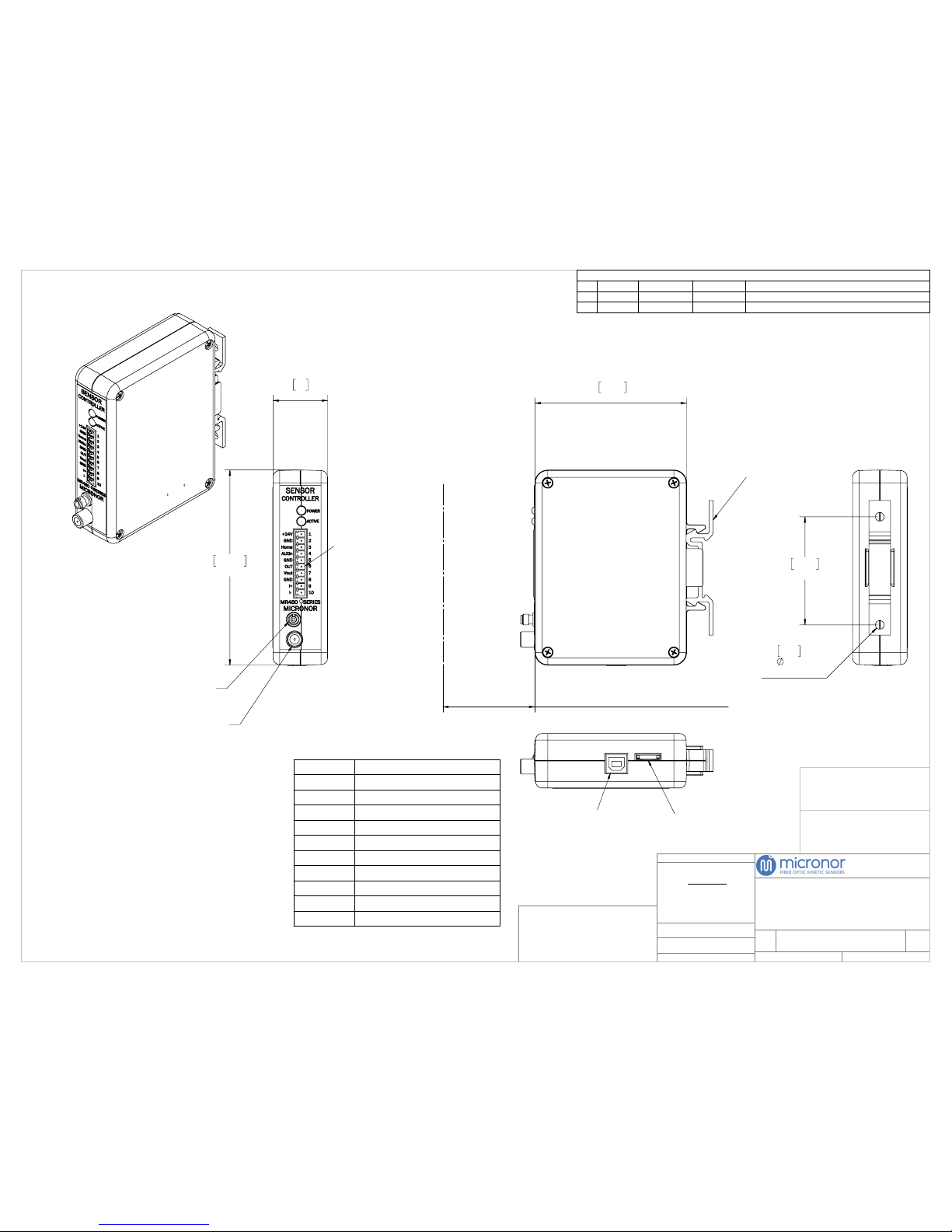
SEE NOTES
SCALE:
DO NOT SCALE DRAWING
SEE NOTES
FINISH:
MATERIAL:
REV
SIZE
DWG. NO.
TITLE:
±.01
±.004
±.0010
±.5°
TWO DECIMAL PLACE:
THREE DECIMAL PLACE:
FOUR DECIMAL PLACE:
ANGULAR:
TOLERANCES:
DIMENSIONS ARE IN INCHES
UNLESS OTHERWISE SPECIFIED:
THE INFORMATION CONTAINED IN THIS DRAWING IS
THE SOLE PROPERTY OF MICRONOR INC. ANY
REPRODUCTION IN PART OR AS A WHOLE WITHOUT
THE WRITTEN PERMISSION OF MICRONOR INC. IS
PROHIBITED.
PROPRIETARY AND CONFIDENTIAL
SHEET:
WWW.MICRONOR.COM
805 389 6600
C
X1
1 OF 1
1:1
114.60
4.51
32
1.26
SMA KEYED INPUT
CONNECTOR
BARE FIBER SOURCE
CONNECTOR
J1
89.10
3.51
MINIMUM REQUIRED DISTANCE
FOR FIBER OPTIC CONNECTION 3.5" [89]
UNIT MOUNTS
ONTO STANDARD
35MM DIN RAIL
63.50
2.50
2X
5.08
0.20
FOR
MOUNTING
USB PORT
PORT FOR CABLE,
MR340-99-XX
1 WARNING: KEEP CONNECTOR COVERS IN PLACE
DURING STORAGE, TO PROTECT FIBER OPTIC
INTERFACES.
NOTES: UNLESS OTHERWISE SPECIFIED
J1 PHOENIX CONTACT P/N: 1803358
(10 PIN TERMINAL), MATING PLUG P/N: 1803659
REVISIONS
REV
DATE
ECN NO.
DRAWN BY
DESCRIPTION
X1
6-13-18
N/A
RGB
RELEASE
TERMINAL
DESCRIPTION
1
+24VDC Power Supply Input
2
Ground Input
3
Home
4
AUX in
5
Ground
6
OUT
7
V out
8
Ground
9
I+
10
I-
MR430-1
CONTROLLER MODULE
MR430-1
Page 46
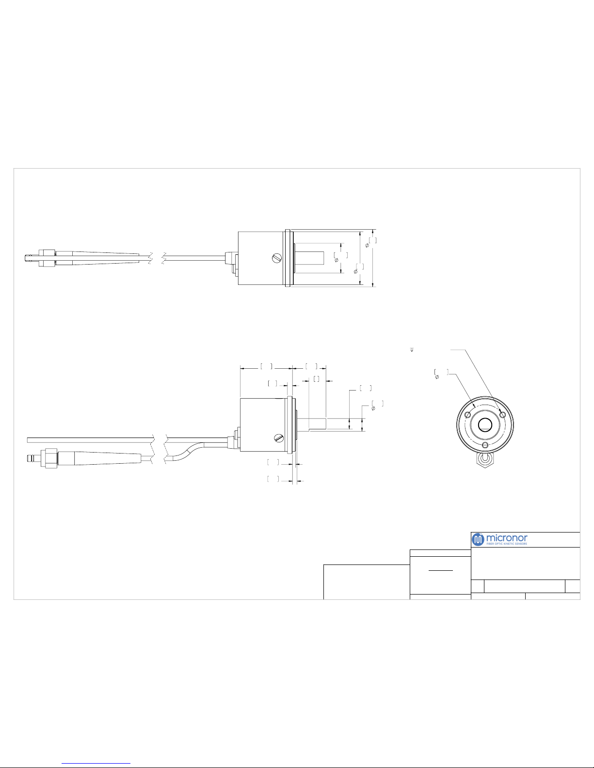
SCALE:
DO NOT SCALE DRAWING
REV
SIZE
DWG. NO.
TITLE:
±.01
±.004
±.0010
±.5°
TWO DECIMAL PLACE:
THREE DECIMAL PLACE:
FOUR DECIMAL PLACE:
ANGULAR:
TOLERANCES:
DIMENSIONS ARE IN INCHES
UNLESS OTHERWISE SPECIFIED:
THE INFORMATION CONTAINED IN THIS DRAWING IS
THE SOLE PROPERTY OF MICRONOR INC. ANY
REPRODUCTION IN PART OR AS A WHOLE WITHOUT
THE WRITTEN PERMISSION OF MICRONOR INC. IS
PROHIBITED.
PROPRIETARY AND CONFIDENTIAL
NOTES: UNLESS OTHERWISE SPECIFIED
SHEET:
WWW.MICRONOR.COM
805 389 6600
C
B
1 OF 4
2:1
24.6
.97
2.4
.09
1.55
.06
2.20
.09
8
.31
15.7
.62
4.98
.20
5.98
.236
3X 4-40 UNC - 2B
.25 MIN [6.4MM]
19.05
.750
25
.984
14.10
.555
27
1.063
MR431
MR431
POSITION SENSOR
4 WARNING: KEEP CONNECTOR COVERS IN PLACE DURING
STORAGE TO PROTECT FIBER OPTIC INTERFACES.
3 WARNING: DO NOT DROP UNIT. DROPPING OR OTHER
SEVERE SHOCK IMPACTS MAY DAMAGE THE UNIT.
2 ALWAYS USE FLEXIBLE COUPLING WHEN MOUNTING SHAFT
TO EXTERNAL EQUIPMENT.
1 DRAWINGS SUBJECT TO CHANGE WITHOUT NOTICE.
FOR LATEST DRAWINGS, VISIT: WWW.MICRONOR.COM
Page 47
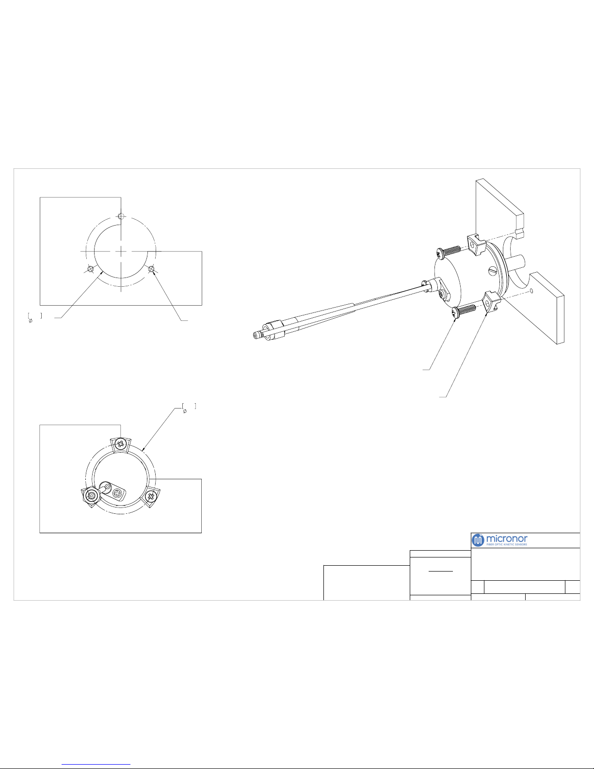
SCALE:
DO NOT SCALE DRAWING
REV
SIZE
DWG. NO.
TITLE:
±.01
±.004
±.0010
±.5°
TWO DECIMAL PLACE:
THREE DECIMAL PLACE:
FOUR DECIMAL PLACE:
ANGULAR:
TOLERANCES:
DIMENSIONS ARE IN INCHES
UNLESS OTHERWISE SPECIFIED:
THE INFORMATION CONTAINED IN THIS DRAWING IS
THE SOLE PROPERTY OF MICRONOR INC. ANY
REPRODUCTION IN PART OR AS A WHOLE WITHOUT
THE WRITTEN PERMISSION OF MICRONOR INC. IS
PROHIBITED.
PROPRIETARY AND CONFIDENTIAL
NOTES: UNLESS OTHERWISE SPECIFIED
SHEET:
WWW.MICRONOR.COM
805 389 6600
C
B
2 OF 4
2:1
33.02
1.30
BOLT PATTERN
25.15
.990
THRU
3X 4-40 UNC - 2B
3X #4-40 NYLON SCREWS
3X SYNCRO CLAMPS
MR431
MR431 MOUNTING
INSTRUCTIONS, SYNCRO
CLAMPS
MOUNTING PLATE
1 DRAWINGS SUBJECT TO CHANGE WITHOUT NOTICE.
FOR LATEST DRAWINGS, VISIT: WWW.MICRONOR.COM
For Set of 3x Synchro Clamps and Screws, Order Micronor P/N MR430-1101
Page 48
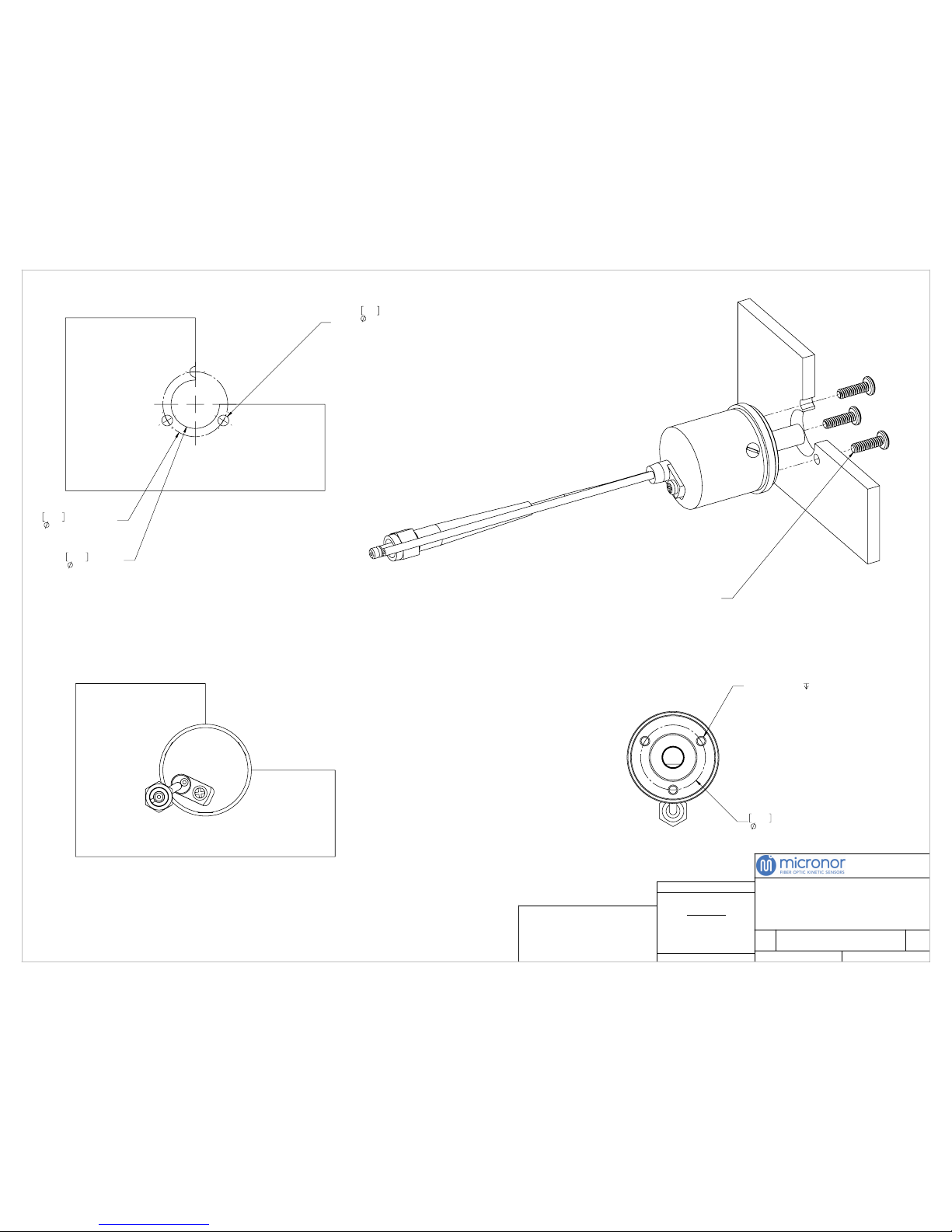
SCALE:
DO NOT SCALE DRAWING
REV
SIZE
DWG. NO.
TITLE:
±.01
±.004
±.0010
±.5°
TWO DECIMAL PLACE:
THREE DECIMAL PLACE:
FOUR DECIMAL PLACE:
ANGULAR:
TOLERANCES:
DIMENSIONS ARE IN INCHES
UNLESS OTHERWISE SPECIFIED:
THE INFORMATION CONTAINED IN THIS DRAWING IS
THE SOLE PROPERTY OF MICRONOR INC. ANY
REPRODUCTION IN PART OR AS A WHOLE WITHOUT
THE WRITTEN PERMISSION OF MICRONOR INC. IS
PROHIBITED.
PROPRIETARY AND CONFIDENTIAL
NOTES: UNLESS OTHERWISE SPECIFIED
SHEET:
WWW.MICRONOR.COM
805 389 6600
C
B
3 OF 4
2:1
14.22
.560
THRU MIN
3X
3.18
.125
THRU,
EQ SPACING AS SHOWN
19.05
.750
HOLE PATTERN
3X 4-40 UNC - 2B
.25 MIN
19.05
.750
FRONT MOUNTING HOLE PATTERN
3X #4-40 NYLON SCREWS
MR431
MR431 MOUNTING
INSTRUCTIONS, FRONT
MOUNT
MOUNTING PLATE
1 DRAWINGS SUBJECT TO CHANGE WITHOUT NOTICE.
FOR LATEST DRAWINGS, VISIT: WWW.MICRONOR.COM
Page 49
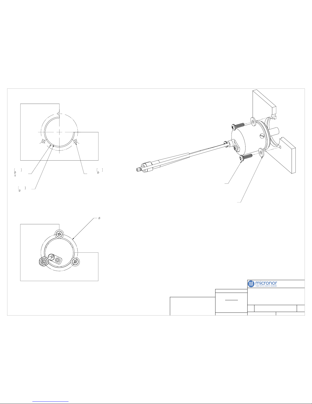
SCALE:
DO NOT SCALE DRAWING
REV
SIZE
DWG. NO.
TITLE:
±.01
±.004
±.0010
±.5°
TWO DECIMAL PLACE:
THREE DECIMAL PLACE:
FOUR DECIMAL PLACE:
ANGULAR:
TOLERANCES:
DIMENSIONS ARE IN INCHES
UNLESS OTHERWISE SPECIFIED:
THE INFORMATION CONTAINED IN THIS DRAWING IS
THE SOLE PROPERTY OF MICRONOR INC. ANY
REPRODUCTION IN PART OR AS A WHOLE WITHOUT
THE WRITTEN PERMISSION OF MICRONOR INC. IS
PROHIBITED.
PROPRIETARY AND CONFIDENTIAL
NOTES: UNLESS OTHERWISE SPECIFIED
SHEET:
WWW.MICRONOR.COM
805 389 6600
C
B
4 OF 4
2:1
1.30 HOLE PATTERN
27.18
1.070
MIN
.089 MAX
25.15
.990
THRU
3X
2.84
.11
THRU,
EQ SPACING AS SHOWN
3X #4-40 NYLON SCREWS
3X #4-40 NYLON WASHERS (OD: 0.312")
MR431
MR431 MOUNTING
INSTRUCTIONS, NYLON
WASHERS
MOUNTING PLATE
1 DRAWINGS SUBJECT TO CHANGE WITHOUT NOTICE.
FOR LATEST DRAWINGS, VISIT: WWW.MICRONOR.COM
Page 50
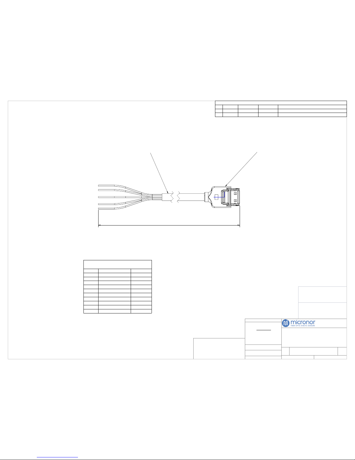
SEE NOTES
SCALE:
DO NOT SCALE DRAWING
SEE NOTES
FINISH:
MATERIAL:
REV
SIZE
DWG. NO.
TITLE:
±.01
±.004
±.0010
±.5°
TWO DECIMAL PLACE:
THREE DECIMAL PLACE:
FOUR DECIMAL PLACE:
ANGULAR:
TOLERANCES:
DIMENSIONS ARE IN INCHES
UNLESS OTHERWISE SPECIFIED:
THE INFORMATION CONTAINED IN THIS DRAWING IS
THE SOLE PROPERTY OF MICRONOR INC. ANY
REPRODUCTION IN PART OR AS A WHOLE WITHOUT
THE WRITTEN PERMISSION OF MICRONOR INC. IS
PROHIBITED.
PROPRIETARY AND CONFIDENTIAL
SHEET:
WWW.MICRONOR.COM
805 389 6600
C
X1
1 OF 1
2:1
1.1m LENGTH (REF)
HIROSE: 3240-10P-C(50)
TO MR430 CONTROLLER
TENSILITY
PN: 30-00534
1 CABLES ARE MADE NOMINALLY 0.1m LONGER THAN
SPECIFIED LENGTH.
NOTES: UNLESS OTHERWISE SPECIFIED
REVISIONS
REV
DATE
ECN NO.
DRAWN BY
DESCRIPTION
X1
6-11-18
N/A
RGB
RELEASE
CONTROLLER CONNECTOR:
Cable Plug: PN: 3240-10P-C(50)
POSITION
FUNCTION
WIRE COLOR
1
+5V
BROWN
2
RS422 - RCV- (input)
RED
3
RS422 - RCV+ (input)
ORANGE
4
RS422 - TX- (ouput)
YELLOW
5
RS422 - TX+ (output)
GREEN
6
GND
BLUE
7
SSI-CLK-
PURPLE
8
SSI-CLK+
GREY
9
SSI-DAT-
WHITE
10
SSI-DAT+
BLACK
MR430-99-01
CONTROLLER CONNECTION
PIGTAIL ASSY,
 Loading...