

Configuration and Use Manual
MMI-20016855, Rev AD
Micro Motion® 9739 MVD Transmitters
June 2019

Safety and approval information
This Micro Motion product complies with all applicable European directives when properly installed in accordance with the
instructions in this manual. Refer to the EU declaration of conformity for directives that apply to this product. The EU declaration
of conformity, with all applicable European directives, and the complete ATEX Installation Drawings and Instructions are available
on the internet at www.emerson.com or through your local Micro Motion support center.
Information affixed to equipment that complies with the Pressure Equipment Directive, can be found on the internet at
www.emerson.com.
For hazardous installations in Europe, refer to standard EN 60079-14 if national standards do not apply.
Other information
Full product specifications can be found in the product data sheet. Troubleshooting information can be found in the configuration
manual. Product data sheets and manuals are available from the Micro Motion web site at www.emerson.com.
Return policy
Follow Micro Motion procedures when returning equipment. These procedures ensure legal compliance with government
transportation agencies and help provide a safe working environment for Micro Motion employees. Micro Motion will not accept
your returned equipment if you fail to follow Micro Motion procedures.
Return procedures and forms are available on our web support site at www.emerson.com, or by phoning the Micro Motion
Customer Service department.
Emerson Flow customer service
Email:
• Worldwide: flow.support@emerson.com
• Asia-Pacific: APflow.support@emerson.com
Telephone:
North and South America
United States 800-522-6277 U.K. 0870 240 1978 Australia 800 158 727
Canada +1 303-527-5200 The Netherlands +31 (0) 704 136
Mexico +41 (0) 41 7686
111
Argentina +54 11 4837 7000 Germany 0800 182 5347 Pakistan 888 550 2682
Brazil +55 15 3413 8000 Italy 8008 77334 China +86 21 2892 9000
Europe and Middle East Asia Pacific
666
France 0800 917 901 India 800 440 1468
Central & Eastern +41 (0) 41 7686
111
Russia/CIS +7 495 981 9811 South Korea +82 2 3438 4600
Egypt 0800 000 0015 Singapore +65 6 777 8211
Oman 800 70101 Thailand 001 800 441 6426
Qatar 431 0044 Malaysia 800 814 008
Kuwait 663 299 01
South Africa 800 991 390
Saudi Arabia 800 844 9564
UAE 800 0444 0684
New Zealand 099 128 804
Japan +81 3 5769 6803
2

Configuration and Use Manual Contents
MMI-20016855 June 2019
Contents
Chapter 1 Before you begin............................................................................................................7
1.1 About this manual............................................................................................................................ 7
1.2 Supported protocols.........................................................................................................................7
1.3 Related documentation....................................................................................................................7
Chapter 2 Quick start..................................................................................................................... 9
2.1 Power up the transmitter..................................................................................................................9
2.2 Check meter status...........................................................................................................................9
2.3 Make a startup connection to the transmitter.................................................................................10
2.4 Characterize the flowmeter (if required).........................................................................................10
2.5 Verify mass flow measurement.......................................................................................................13
2.6 Verify the zero................................................................................................................................ 14
Chapter 3 Introduction to configuration and commissioning........................................................17
3.1 Configuration flowchart................................................................................................................. 17
3.2 Default values and ranges...............................................................................................................18
3.3 Enable access to the off-line menu of the display............................................................................ 18
3.4 Disable write-protection on the transmitter configuration............................................................. 18
3.5 Disable HART security.....................................................................................................................18
3.6 Restore the factory configuration................................................................................................... 19
Chapter 4 Configure process measurement..................................................................................21
4.1 Configure mass flow measurement................................................................................................ 21
4.2 Configure volume flow measurement for liquid applications.......................................................... 25
4.3 Configure GSV flow measurement..................................................................................................30
4.4 Configure Flow Direction ............................................................................................................... 34
4.5 Configure density measurement ....................................................................................................39
4.6 Configure temperature measurement............................................................................................43
4.7 Configure the petroleum measurement application.......................................................................45
4.8 Set up concentration measurement ...............................................................................................50
4.9 Configure pressure compensation..................................................................................................56
Chapter 5 Configure device options and preferences....................................................................61
5.1 Configure the transmitter display................................................................................................... 61
5.2 Enable or disable operator actions from the display........................................................................64
5.3 Configure security for the display menus........................................................................................66
5.4 Configure response time parameters............................................................................................. 67
5.5 Configure alert handling.................................................................................................................69
5.6 Configure informational parameters.............................................................................................. 72
Chapter 6 Integrate the meter with the control system................................................................ 75
6.1 Configure the mA Output...............................................................................................................75
Configuration and Use Manual iii

Contents Configuration and Use Manual
June 2019 MMI-20016855
6.2 Configure the Frequency Output.................................................................................................... 80
6.3 Configure the Discrete Output....................................................................................................... 84
6.4 Configure the Discrete Input.......................................................................................................... 89
6.5 Configure the mA Input.................................................................................................................. 91
6.6 Configure events............................................................................................................................ 93
6.7 Configure digital communications................................................................................................. 94
6.8 Set up polling for temperature..................................................................................................... 103
6.9 Set up polling for pressure............................................................................................................ 104
Chapter 7 Complete the configuration....................................................................................... 107
7.1 Back up transmitter configuration................................................................................................ 107
7.2 Enable HART security....................................................................................................................107
7.3 Enable write-protection on the transmitter configuration............................................................ 108
Chapter 8 Transmitter operation................................................................................................109
8.1 Record the process variables........................................................................................................ 109
8.2 View process variables..................................................................................................................109
8.3 View transmitter status using the status LED................................................................................ 111
8.4 View and acknowledge status alerts............................................................................................. 112
8.5 Read totalizer and inventory values.............................................................................................. 116
8.6 Start and stop totalizers and inventories.......................................................................................116
8.7 Reset totalizers.............................................................................................................................117
8.8 Reset inventories..........................................................................................................................119
Chapter 9 Measurement support................................................................................................121
9.1 Options for measurement support............................................................................................... 121
9.2 Zero the meter............................................................................................................................. 121
9.3 Validate the meter........................................................................................................................122
9.4 Perform a (standard) D1 and D2 density calibration......................................................................124
9.5 Perform a D3 and D4 density calibration (T-Series sensors only)................................................... 126
9.6 Perform temperature calibration..................................................................................................129
Chapter 10 Troubleshooting........................................................................................................ 133
10.1 Transmitter status reported by LED............................................................................................ 133
10.2 Check the cutoffs....................................................................................................................... 133
10.3 Density measurement problems................................................................................................ 134
10.4 Check the drive gain................................................................................................................... 135
10.5 Check for internal electrical problems........................................................................................ 136
10.6 Check Flow Direction ................................................................................................................. 138
10.7 Flow measurement problems .................................................................................................... 138
10.8 Frequency Output problems.......................................................................................................141
10.9 Check Frequency Output Fault Action ........................................................................................141
10.10 Check Frequency Output Scaling Method ................................................................................ 142
10.11 Check grounding......................................................................................................................142
iv Micro Motion 9739 MVD Transmitters

Configuration and Use Manual Contents
MMI-20016855 June 2019
10.12 Check HART Address and mA Output Action............................................................................ 142
10.13 Check HART burst mode...........................................................................................................142
10.14 Check the HART communication loop...................................................................................... 143
10.15 Locate a device using the HART 7 Squawk feature.................................................................... 143
10.16 Perform loop tests....................................................................................................................144
10.17 Check Lower Range Value and Upper Range Value ...................................................................148
10.18 Milliamp output problems........................................................................................................148
10.19 Check mA Output Fault Action .................................................................................................150
10.20 Trim mA Output....................................................................................................................... 150
10.21 Check the pickoff voltage......................................................................................................... 151
10.22 Check power supply wiring.......................................................................................................153
10.23 Check for radio frequency interference (RFI).............................................................................153
10.24 Using sensor simulation for troubleshooting............................................................................ 154
10.25 Status alerts, causes, and recommendations............................................................................154
10.26 Check sensor-to-transmitter wiring.......................................................................................... 169
10.27 Check for two-phase flow (slug flow)........................................................................................169
10.28 Temperature measurement problems......................................................................................170
Appendix A Using the transmitter display..................................................................................... 171
A.1 Components of the transmitter interface..................................................................................... 171
A.2 Use the optical switches............................................................................................................... 172
A.3 Access and use the display menu system......................................................................................173
A.4 Display codes for process variables...............................................................................................176
A.5 Codes and abbreviations used in display menus........................................................................... 178
Appendix B Using ProLink III with the transmitter......................................................................... 181
B.1 Basic information about ProLink III ...............................................................................................181
B.2 Connect with ProLink III ............................................................................................................... 182
Appendix C Using a Field Communicator with the transmitter...................................................... 187
C.1 Basic information about the Field Communicator ........................................................................187
C.2 Connect with the Field Communicator ........................................................................................ 188
Appendix D Default values and ranges.......................................................................................... 193
D.1 Default values and ranges............................................................................................................ 193
Appendix E Transmitter components and installation wiring........................................................199
E.1 Input/output (I/O) terminals.........................................................................................................199
Configuration and Use Manual v

Contents Configuration and Use Manual
June 2019 MMI-20016855
vi Micro Motion 9739 MVD Transmitters

Configuration and Use Manual Before you begin
MMI-20016855 June 2019
1 Before you begin
1.1 About this manual
This manual helps you configure, commission, use, maintain, and troubleshoot the 9739 MVD transmitter.
Important
This manual assumes that the following conditions apply:
• The transmitter has been installed correctly and completely according to the instructions in the
transmitter installation manual
• The installation complies with all applicable safety requirements
• The user is trained in government and corporate safety standards
1.2 Supported protocols
The 9739 MVD transmitter supports the following protocols.
Communication tool Supported protocols
ProLink III • HART/RS-485
• HART/Bell 202
• Modbus/RS-485
• Service port
Field Communicator HART/Bell 202
For information about how to use the communication tools, see the appendices in this manual.
Tip
You may be able to use other communications tools, such as AMS Suite: Intelligent Device Manager, or the
Smart Wireless THUM™ Adapter. Use of AMS or the Smart Wireless THUM Adapter is not discussed in this
manual. For more information on the Smart Wireless THUM Adapter, refer to the documentation available at
www.emerson.com.
1.3 Related documentation
You can find all product documentation on the product documentation DVD shipped with the product or at
www.emerson.com.
See any of the following documents for more information:
• Micro Motion Model 9739 Transmitters with MVD Technology Product Data Sheet
• Micro Motion 9739 MVD Transmitters: Installation Manual
• Micro Motion 9739 MVD Transmitter Electronics Module Installation Guide
• For hazardous area installation, see the approval documentation shipped with the transmitter, or
download the appropriate documentation from www.emerson.com
Configuration and Use Manual 7

Before you begin Configuration and Use Manual
June 2019 MMI-20016855
• Sensor documentation
8 Micro Motion 9739 MVD Transmitters

Configuration and Use Manual Quick start
MMI-20016855 June 2019
2 Quick start
2.1 Power up the transmitter
The transmitter must be powered up for all configuration and commissioning tasks, or for process
measurement.
Procedure
1. Ensure that all transmitter and sensor covers and seals are closed.
DANGER
To prevent ignition of flammable or combustible atmospheres, ensure that all covers and seals are
tightly closed. For hazardous area installations, applying power while housing covers are removed or
loose can cause an explosion.
2. Turn on the electrical power at the power supply.
The transmitter will automatically perform diagnostic routines. The transmitter is self-switching and
will automatically detect the supply voltage. When using DC power, a minimum of 1.5 amps of startup
current is required. During this period, Alert 009 is active. The diagnostic routines should complete in
approximately 30 seconds. The status LED will turn green when the startup diagnostics are complete. If
the status LED exhibits different behavior, an alert is active.
Postrequisites
Although the sensor is ready to receive process fluid shortly after power-up, the electronics can take up to
10 minutes to reach thermal equilibrium. Therefore, if this is the initial startup, or if power has been off long
enough to allow components to reach ambient temperature, allow the electronics to warm up for
approximately 10 minutes before relying on process measurements. During this warm-up period, you may
observe minor measurement instability or inaccuracy.
2.2 Check meter status
Check the meter for any error conditions that require user action or that affect measurement accuracy.
Procedure
1. Wait approximately 10 seconds for the power-up sequence to complete.
Immediately after power-up, the transmitter runs through diagnostic routines and checks for error
conditions. During the power-up sequence, Alert A009 is active. This alert should clear automatically
when the power-up sequence is complete.
2. Check the status LED on the transmitter.
2.2.1 Transmitter status reported by LED
Table 2-1: Status LED states
LED behavior Alarm condition Description
Solid green No alarm Normal operation
Configuration and Use Manual 9
Quick start Configuration and Use Manual
June 2019 MMI-20016855
Table 2-1: Status LED states (continued)
LED behavior Alarm condition Description
Flashing yellow No alarm • Zero calibration procedure is in progress
• Loop test is in progress
Solid yellow Low-severity alarm Alarm condition that will not cause measurement error
(outputs continue to report process data)
Solid red High-severity alarm Alarm condition that will cause measurement error
(outputs in fault)
2.3 Make a startup connection to the transmitter
For all configuration tools except the display, you must have an active connection to the transmitter to
configure the transmitter. Follow this procedure to make your first connection to the transmitter.
Procedure
Identify the connection type to use, and follow the instructions for that connection type in the appropriate
appendix. Use the default communications parameters shown in the appendix.
Communications tool Connection type to use Instructions
ProLink III Modbus/RS-485 Using ProLink III with the transmitter
Field Communicator HART Using a Field Communicator with the
transmitter
2.4 Characterize the flowmeter (if required)
Display
ProLink III Device Tools → Calibration Data
Field Communicator Configure → Manual Setup → Characterize
Characterizing the flowmeter adjusts your transmitter to match the unique traits of the sensor it is paired
with. The characterization parameters (also called calibration parameters) describe the sensor’s sensitivity to
flow, density, and temperature. Depending on your sensor type, different parameters are required. Values for
your sensor are provided by Micro Motion on the sensor tag or the calibration certificate.
Tip
If your flowmeter was ordered as a unit, it has already been characterized at the factory. However, you should
still verify the characterization parameters.
Procedure
1. Specify Sensor Type.
• Straight-tube (T-Series)
Not available
• Curved-tube (all sensors except T-Series)
2. Set the flow characterization parameters. Be sure to include all decimal points.
• For straight-tube sensors, set FCF (Flow Cal or Flow Calibration Factor), FTG, and FFQ.
10 Micro Motion 9739 MVD Transmitters
0
1
Configuration and Use Manual Quick start
MMI-20016855 June 2019
• For curved-tube sensors, set Flow Cal (Flow Calibration Factor).
3. Set the density characterization parameters.
• For straight-tube sensors, set D1, D2, DT, DTG, K1, K2, FD, DFQ1, and DFQ2.
• For curved-tube sensors, set D1, D2, TC, K1, K2, and FD. (TC is sometimes shown as DT.)
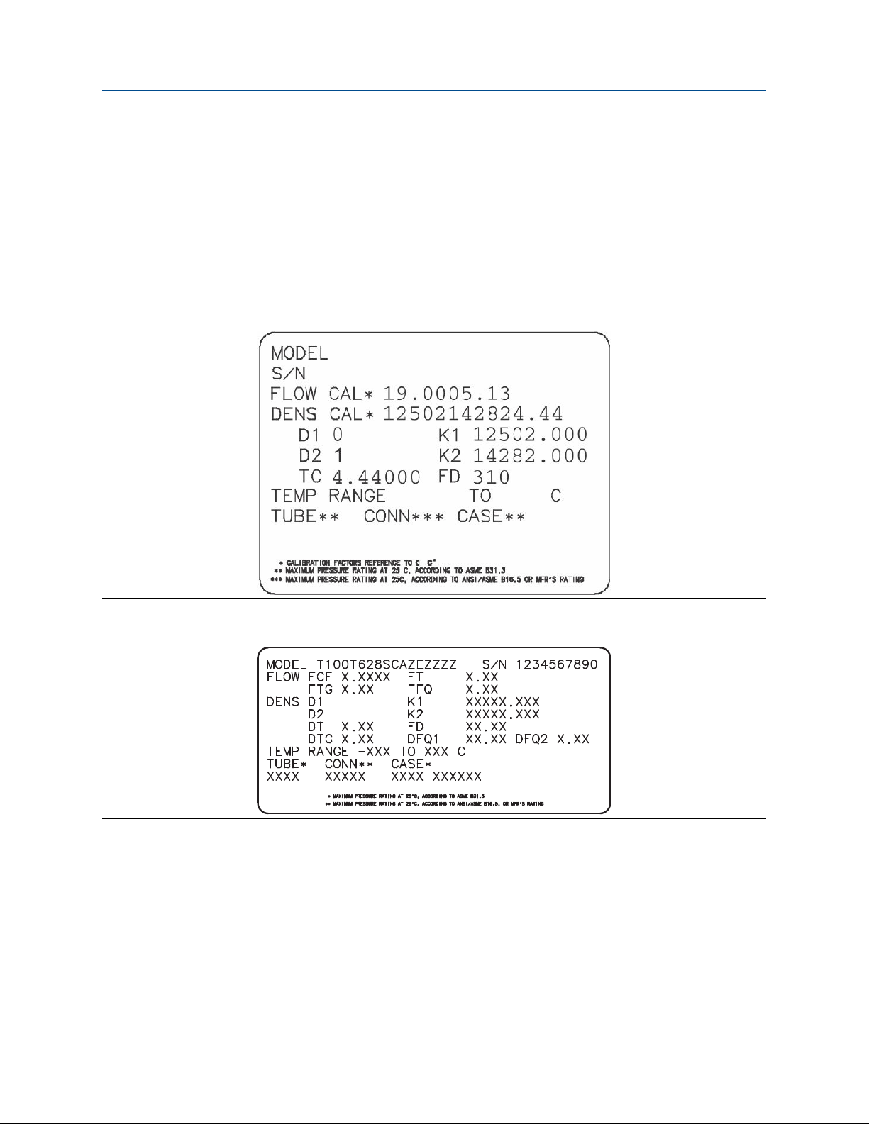
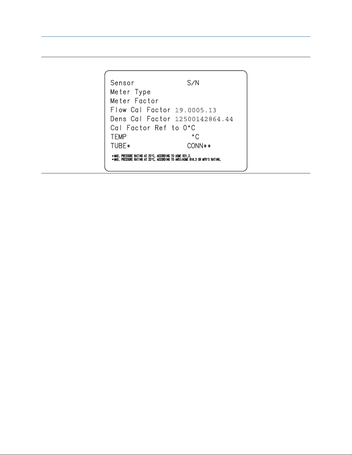
2.4.1 Sample sensor tags
Figure 2-1: Tag on newer curved-tube sensors (all sensors except T-Series)
Figure 2-2: Tag on older straight-tube sensor (T-Series)
Configuration and Use Manual 11

0
1
Quick start Configuration and Use Manual
June 2019 MMI-20016855
Figure 2-3: Tag on newer straight-tube sensor (T-Series)
2.4.2 Flow calibration parameters (FCF, FT)
Two separate values are used to describe flow calibration: a 6-character FCF value and a 4-character FT value.
They are provided on the sensor tag.
Both values contain decimal points. The 10-character string is called either Flowcal or FCF.
If your sensor tag shows the FCF and the FT values separately and you need to enter a single value,
concatenate the two values to form the single parameter value, retaining both decimal points.
2.4.3 Density calibration parameters (D1, D2, K1, K2, FD, DT, TC)
Density calibration parameters are typically on the sensor tag and the calibration certificate.
If your sensor tag does not show a D1 or D2 value:
• For D1, enter the Dens A or D1 value from the calibration certificate. This value is the line-condition
density of the low-density calibration fluid. Micro Motion uses air. If you cannot find a Dens A or D1 value,
enter 0.001 g/cm3.
• For D2, enter the Dens B or D2 value from the calibration certificate. This value is the line-condition density
of the high-density calibration fluid. Micro Motion uses water. If you cannot find a Dens B or D2 value,
enter 0.998g/cm3 .
If your sensor tag does not show a K1 or K2 value:
• For K1, enter the first 5 digits of the density calibration factor. In this sample tag, this value is shown as
12500.
• For K2, enter the second 5 digits of the density calibration factor. In this sample tag, this value is shown as
14286.
12 Micro Motion 9739 MVD Transmitters
Configuration and Use Manual Quick start
MMI-20016855 June 2019
Figure 2-4: K1, K2, and TC values in the density calibration factor
If your sensor does not show an FD value, contact customer service.
If your sensor tag does not show a DT or TC value, enter the last 4 characters of the density calibration factor.
In the sample tag shown above, the value is shown as 4.44.
Do not confuse the Meter Factor line on the pictured sensor tag with any meter factor settings discussed in
this manual.
The Meter Type value is not relevant on a 9739 MVD transmitter.
2.5 Verify mass flow measurement
Check to see that the mass flow rate reported by the transmitter is accurate. You can use any available
method.
Procedure
• Read the value for Mass Flow Rate on the transmitter display.
• Connect to the transmitter with ProLink III and read the value for Mass Flow Rate in the Process Variables
panel.
• Connect to the transmitter with the Field Communicator and read the value for Mass Flow Rate.
Postrequisites
If the reported mass flow rate is not accurate:
• Check the characterization parameters.
• Review the troubleshooting suggestions for flow measurement issues.
Related information
Flow measurement problems
Configuration and Use Manual 13

Quick start Configuration and Use Manual
June 2019 MMI-20016855
2.6 Verify the zero
Verifying the zero helps you determine if the stored zero value is appropriate to your installation, or if a field
zero can improve measurement accuracy.
The zero verification procedure analyzes the Live Zero value under conditions of zero flow, and compares it to
the Zero Stability range for the sensor. If the average Live Zero value is within a reasonable range, the zero
value stored in the transmitter is valid. Performing a field calibration will not improve measurement accuracy.
Important
In most cases, the factory zero is more accurate than the field zero. Do not zero the meter unless one of the
following is true:
• The zero is required by site procedures.
• The stored zero value fails the zero verification procedure.
Procedure
1. Allow the flowmeter to warm up for at least 20 minutes after applying power.
2. Run the process fluid through the sensor until the sensor temperature reaches the normal process
operating temperature.
3. Stop flow through the sensor by shutting the downstream valve, and then the upstream valve if
available.
4. Verify that the sensor is blocked in, that flow has stopped, and that the sensor is completely full of
process fluid.
5. From ProLink III, choose Device Tools → Calibration → Zero Verification and Calibration → Verify
Zero and wait until the procedure completes.
6. Observe the drive gain, temperature, and density readings. If they are stable, check the Live Zero or
Field Verification Zero value. If the average value is close to 0, you should not need to zero the meter.
7. If the zero verification procedure fails:
a) Confirm that the sensor is completely blocked in, that flow has stopped, and that the sensor is
completely full of process fluid.
b) Verify that the process fluid is not flashing or condensing, and that it does not contain particles
that can settle out.
c) Remove or reduce sources of electromechanical noise if appropriate.
d) Repeat the zero verification procedure.
e) If it fails again, zero the meter.
Postrequisites
Restore normal flow through the sensor by opening the valves.
Related information
Zero the meter
14 Micro Motion 9739 MVD Transmitters

Configuration and Use Manual Quick start
MMI-20016855 June 2019
2.6.1 Terminology used with zero verification and zero calibration
Term Definition
Zero In general, the offset required to synchronize the left pickoff and the right pickoff under
conditions of zero flow. Unit = microseconds.
Factory Zero The zero value obtained at the factory, under laboratory conditions.
Field Zero The zero value obtained by performing a zero calibration outside the factory.
Prior Zero The zero value stored in the transmitter at the time a field zero calibration is begun. May
be the factory zero or a previous field zero.
Manual Zero The zero value stored in the transmitter, typically obtained from a zero calibration
procedure. It may also be configured manually. Also called “mechanical zero” or “stored
zero”.
Live Zero The real-time bidirectional mass flow rate with no flow damping or mass flow cutoff
applied. An adaptive damping value is applied only when the mass flow rate changes
dramatically over a very short interval. Unit = configured mass flow measurement unit.
Zero Stability A laboratory-derived value used to calculate the expected accuracy for a sensor. Under
laboratory conditions at zero flow, the average flow rate is expected to fall within the
range defined by the Zero Stability value (0 ± Zero Stability). Each sensor size and model
has a unique Zero Stability value. Statistically, 95% of all data points should fall within the
range defined by the Zero Stability value.
Zero Calibration The procedure used to determine the zero value.
Zero Time The time period over which the Zero Calibration procedure is performed. Unit = seconds.
Field Verification Zero A 3-minute running average of the Live Zero value, calculated by the transmitter. Unit =
configured mass flow measurement unit.
Zero Verification A procedure used to evaluate the stored zero and determine whether or not a field zero
can improve measurement accuracy.
Configuration and Use Manual 15

Quick start Configuration and Use Manual
June 2019 MMI-20016855
16 Micro Motion 9739 MVD Transmitters
Configuration and Use Manual Introduction to configuration and commissioning
MMI-20016855 June 2019
3 Introduction to configuration and commissioning
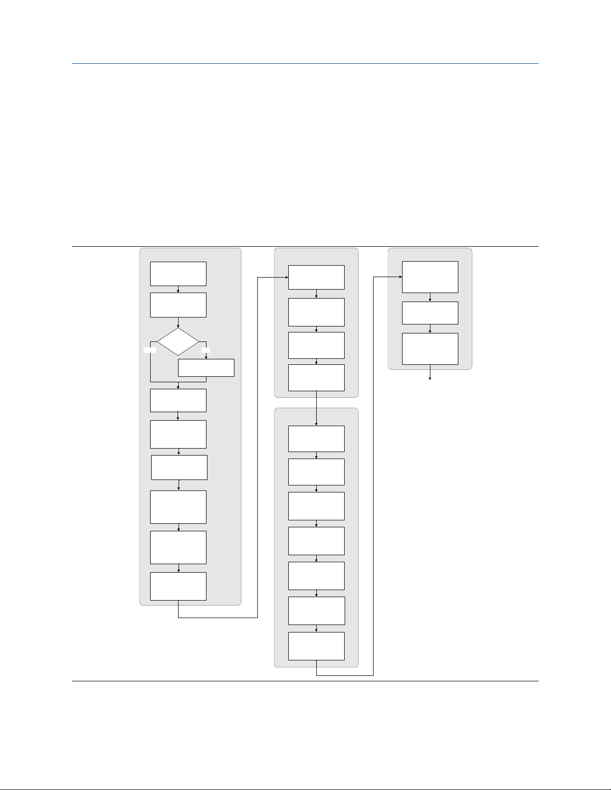
3.1 Configuration flowchart
Use the following flowchart as a general guide to the configuration and commissioning process.
Some options may not apply to your installation. Detailed information is provided in the remainder of this
manual.
Configure process measurement
Configure mass flow
measurement
Configure volume flow
meaurement
Configure device options and
preferences
Configure display
parameters
Configure fault handling
parameters
Test and move to production
Test or tune transmitter
using sensor simulation
Back up transmitter
configuration
Volume flow type
Liquid
Configure flow direction
Configure density
measurement
Configure temperature
measurement
Configure petroleum
measurement (API)
application (if available)
Configure concentration
measurement application
(if available)
Configure pressure
compensation (optional)
Gas
Define gas properties
Configure sensor
parameters
Configure device
parameters
Integrate device with control system
Configure the mA
output(s)
Configure the frequency
output(s)
Configure the discrete
output(s)
Configure the discrete
input
Configure the mA input
Configure events
Enable write-protection on
transmitter configuration
Done
Configure digital
communications
Configuration and Use Manual 17
Introduction to configuration and commissioning Configuration and Use Manual
June 2019 MMI-20016855
3.2 Default values and ranges
See Default values and ranges to view the default values and ranges for the most commonly used parameters.
3.3 Enable access to the off-line menu of the display
Display OFF-LINE MAINT → OFF-LINE CONFG → DISPLAY → OFFLN
ProLink III Device Tools → Configuration → Transmitter Display → Display Security
Field Communicator Not available
By default, access to the off-line menu of the display is enabled. If it is disabled, you must enable it if you want
to use the display to configure the transmitter.
Restriction
You cannot use the display to enable access to the off-line menu. You must make a connection from another
tool.
3.4 Disable write-protection on the transmitter
configuration
Display
ProLink III Device Tools → Configuration → Write-Protection
If the transmitter is write-protected, the configuration is locked and you must unlock it before you can change
any configuration parameters. By default, the transmitter is not write-protected.
Tip
Write-protecting the transmitter prevents accidental changes to configuration. It does not prevent normal
operational use. You can always disable write-protection, perform any required configuration changes, then
re-enable write-protection.
OFF-LINE MAINT → CONFG → LOCK
3.5 Disable HART security
If you plan to use HART protocol to configure the device, HART security must be disabled. HART security is
disabled by default, so you may not need to do this.
Prerequisites
Check the setting of the HART security switch. You do not have to remove the housing cover to check the
setting.
Procedure
1. Power down the device.
18 Micro Motion 9739 MVD Transmitters
A
B
Configuration and Use Manual Introduction to configuration and commissioning
MMI-20016855 June 2019
CAUTION
If the transmitter is in a hazardous area, you must power down the device before removing the
transmitter housing cover. Removing the housing cover while the device is powered could cause an
explosion.
2. Remove the transmitter housing cover.
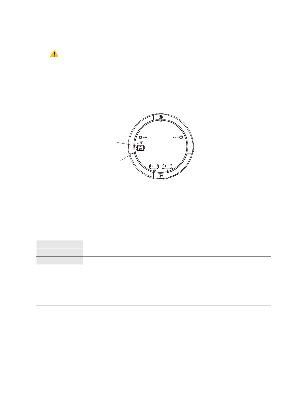
3. Move the HART security switch to the OFF position.
Figure 3-1: HART security switch (on blank display)
A. HART security switch
B. Unused
4. Replace the transmitter housing cover.
5. Power up the device.
3.6 Restore the factory configuration
Display
ProLink III Device Tools → Configuration Transfer → Restore Factory Configuration
Field Communicator Service Tools → Maintenance → Reset/Restore → Restore Factory Configuration
Restoring the factory configuration returns the transmitter to the same configuration it had when it left the
factory. This may be useful if you experience problems during configuration.
Tip
Restoring the factory configuration is not a common action. You may want to contact customer support to
see if there is a preferred method to resolve any issues.
Not available
Configuration and Use Manual 19

Introduction to configuration and commissioning Configuration and Use Manual
June 2019 MMI-20016855
20 Micro Motion 9739 MVD Transmitters
Configuration and Use Manual Configure process measurement
MMI-20016855 June 2019
4 Configure process measurement
4.1 Configure mass flow measurement
The mass flow measurement parameters control how mass flow is measured and reported.
4.1.1 Configure Mass Flow Measurement Unit
Display OFF-LINE MAINT → OFF-LINE CONFG → UNITS → MASS
ProLink III Device Tools → Configuration → Process Measurement → Flow
Field Communicator Configure → Manual Setup → Measurements → Flow → Mass Flow Unit
Mass Flow Measurement Unit specifies the unit of measure that will be used for the mass flow rate. The unit
used for mass total and mass inventory is derived from this unit.
Procedure
Set Mass Flow Measurement Unit to the unit you want to use.
The default setting for Mass Flow Measurement Unit is g/sec (grams per second).
Tip
If the measurement unit you want to use is not available, you can define a special measurement unit.
Options for Mass Flow Measurement Unit
The transmitter provides a standard set of measurement units for Mass Flow Measurement Unit, plus one
user-defined special measurement unit. Different communications tools may use different labels for the
units.
Label
Unit description
Grams per second G/S g/sec g/s
Grams per minute G/MIN g/min g/min
Grams per hour G/H g/hr g/h
Kilograms per second KG/S kg/sec kg/s
Kilograms per minute KG/MIN kg/min kg/min
Kilograms per hour KG/H kg/hr kg/h
Kilograms per day KG/D kg/day kg/d
Display ProLink III Field Communicator
Metric tons per minute T/MIN mTon/min MetTon/min
Metric tons per hour T/H mTon/hr MetTon/h
Metric tons per day T/D mTon/day MetTon/d
Pounds per second LB/S lbs/sec lb/s
Pounds per minute LB/MIN lbs/min lb/min
Configuration and Use Manual 21

Configure process measurement Configuration and Use Manual
June 2019 MMI-20016855
Label
Unit description
Pounds per hour LB/H lbs/hr lb/h
Pounds per day LB/D lbs/day lb/d
Short tons (2000 pounds) per
minute
Short tons (2000 pounds) per hour ST/H sTon/hr STon/h
Short tons (2000 pounds) per day ST/D sTon/day STon/d
Long tons (2240 pounds) per hour LT/H lTon/hr LTon/h
Long tons (2240 pounds) per day LT/D lTon/day LTon/d
Special unit SPECL special Spcl
Display ProLink III Field Communicator
ST/MIN sTon/min STon/min
Define a special measurement unit for mass flow
Display Not available
ProLink III Device Tools → Configuration → Process Measurement → Flow → Special Units
Field Communicator Configure → Manual Setup → Measurements → Special Units → Mass Special Units
A special measurement unit is a user-defined unit of measure that allows you to report process data, totalizer
data, and inventory data in a unit that is not available in the transmitter. A special measurement unit is
calculated from an existing measurement unit using a conversion factor.
Note
Although you cannot define a special measurement unit using the display, you can use the display to select an
existing special measurement unit, and to view process data using the special measurement unit.
Procedure
1. Specify Base Mass Unit.
Base Mass Unit is the existing mass unit that the special unit will be based on.
2. Specify Base Time Unit.
Base Time Unit is the existing time unit that the special unit will be based on.
3. Calculate Mass Flow Conversion Factor as follows:
a) x base units = y special units
b) Mass Flow Conversion Factor = x ÷ y
The original mass flow rate value is divided by this value.
4. Enter Mass Flow Conversion Factor.
5. Set Mass Flow Label to the name you want to use for the mass flow unit.
6. Set Mass Total Label to the name you want to use for the mass total and mass inventory unit.
The special measurement unit is stored in the transmitter. You can configure the transmitter to use the
special measurement unit at any time.
22 Micro Motion 9739 MVD Transmitters

Configuration and Use Manual Configure process measurement
MMI-20016855 June 2019
Defining a special measurement unit for mass flow
You want to measure mass flow in ounces per second (oz/sec).
1. Set Base Mass Unit to Pounds (lb).
2. Set Base Time Unit to Seconds (sec).
3. Calculate Mass Flow Conversion Factor:
a. 1 lb/sec = 16 oz/sec
b. Mass Flow Conversion Factor = 1 ÷ 16 = 0.0625
4. Set Mass Flow Conversion Factor to 0.0625.
5. Set Mass Flow Label to oz/sec.
6. Set Mass Total Label to oz.
4.1.2 Configure Flow Damping
Display Not available
ProLink III Device Tools → Configuration → Process Measurement → Flow
Field Communicator Configure → Manual Setup → Measurements → Flow → Flow Damping
Damping is used to smooth out small, rapid fluctuations in process measurement. Damping Value specifies
the time period (in seconds) over which the transmitter will spread changes in the process variable. At the end
of the interval, the internal value will reflect 63% of the change in the actual measured value.
Procedure
Set Flow Damping to the value you want to use.
• The default value is 0.8 seconds.
• The flow damping range is 0 to 51.2 seconds when Update Rate is set to Normal.
• The flow damping range is 0 to 10.24 seconds when Update Rate is set to Special.
Tip
• A high damping value makes the process variable appear smoother because the reported value changes
slowly.
• A low damping value makes the process variable appear more erratic because the reported value changes
more quickly.
• The combination of a high damping value and rapid, large changes in flow rate can result in increased
measurement error.
• Whenever the damping value is non-zero, the reported measurement will lag the actual measurement
because the reported value is being averaged over time.
• In general, lower damping values are preferable because there is less chance of data loss, and less lag time
between the actual measurement and the reported value.
The value you enter is automatically rounded down to the nearest valid value.
Configuration and Use Manual 23

Configure process measurement Configuration and Use Manual
June 2019 MMI-20016855
If Flow Damping is set to Normal, the valid values are: 0, 0.2, 0.4, 0.8, 1.6, 3.2, 6.4, 12.8, 25.6, and 51.2.
If Flow Damping is set to Special, the valid values are: 0, 0.04, 0.08, 0.16, 0.32, 0.64, 1.28, 2.56, 5.12, and
10.24.
Effect of flow damping on volume measurement
Flow damping affects volume measurement for liquid volume data. Flow damping also affects volume
measurement for gas standard volume data. The transmitter calculates volume data from the damped mass
flow data.
Interaction between Flow Damping and mA Output Damping
In some circumstances, both Flow Damping and mA Output Damping are applied to the reported mass flow
value.
Flow Damping controls the rate of change in flow process variables. mA Output Damping controls the rate
of change reported via the mA Output. If mA Output Process Variable is set to Mass Flow Rate, and both
Flow Damping and mA Output Damping are set to non-zero values, flow damping is applied first, and the
added damping calculation is applied to the result of the first calculation.
4.1.3 Configure Mass Flow Cutoff
Display Not available
ProLink III Device Tools → Configuration → Process Measurement → Flow
Field Communicator Configure → Manual Setup → Measurements → Flow → Mass Flow Cutoff
Mass Flow Cutoff specifies the lowest mass flow rate that will be reported as measured. All mass flow rates
below this cutoff will be reported as 0.
Procedure
Set Mass Flow Cutoff to the value you want to use.
The default value for Mass Flow Cutoff is 0.0 g/sec or a sensor-specific value set at the factory. The
recommended value is 0.5% of the nominal flow rate of the attached sensor. See the sensor specifications.
Leaving Mass Flow Cutoff at 0 is not recommended.
Effect of Mass Flow Cutoff on volume measurement
Mass Flow Cutoff does not affect volume measurement. Volume data is calculated from the actual mass data
rather than the reported value.
Volume flow has a separate Volume Flow Cutoff that is not affected by the Mass Flow Cutoff value.
Interaction between Mass Flow Cutoff and mA Output Cutoff
Mass Flow Cutoff defines the lowest mass flow value that the transmitter will report as measured. mA
Output Cutoff defines the lowest flow rate that will be reported via the mA Output. If mA Output Process
24 Micro Motion 9739 MVD Transmitters

Configuration and Use Manual Configure process measurement
MMI-20016855 June 2019
Variable is set to Mass Flow Rate, the mass flow rate reported via the mA Output is controlled by the higher of
the two cutoff values.
Mass Flow Cutoff affects all reported values and values used in other transmitter behavior (e.g., events
defined on mass flow).
mA Output Cutoff affects only mass flow values reported via the mA Output.
Cutoff interaction with mA Output Cutoff lower than Mass Flow Cutoff
Configuration:
• mA Output Process Variable: Mass Flow Rate
• Frequency Output Process Variable: Mass Flow Rate
• mA Output Cutoff: 10 g/sec
• Mass Flow Cutoff: 15 g/sec
Result: If the mass flow rate drops below 15 g/sec, mass flow will be reported as 0, and 0 will be used in all
internal processing.
Cutoff interaction with mA Output Cutoff higher than Mass Flow Cutoff
Configuration:
• mA Output Process Variable: Mass Flow Rate
• Frequency Output Process Variable: Mass Flow Rate
• mA Output Cutoff: 15 g/sec
• Mass Flow Cutoff: 10 g/sec
Result:
• If the mass flow rate drops below 15 g/sec but not below 10 g/sec:
— The mA Output will report zero flow.
— The Frequency Output will report the actual flow rate, and the actual flow rate will be used in all
internal processing.
• If the mass flow rate drops below 10 g/sec, both outputs will report zero flow, and 0 will be used in all
internal processing.
4.2 Configure volume flow measurement for liquid
applications
The volume flow measurement parameters control how liquid volume flow is measured and reported.
Restriction
You cannot implement both liquid volume flow and gas standard volume flow at the same time. Choose one
or the other.
4.2.1 Configure Volume Flow Type for liquid applications
Display
Configuration and Use Manual 25
OFF-LINE MAINT → OFF-LINE CONFG → VOL → VOL TYPE LIQUID
Configure process measurement Configuration and Use Manual
June 2019 MMI-20016855
ProLink III Device Tools → Configuration → Process Measurement → Flow
Field Communicator Configure → Manual Setup → Measurements → Gas Standard Volume → Volume Flow Type → Liquid
Volume Flow Type controls whether liquid or gas standard volume flow measurement will be used.
Restriction
Gas standard volume measurement is incompatible with some applications. Set Volume Flow Type to Liquid
if you are using any of the following applications:
• Petroleum measurement
• Concentration measurement
Procedure
Set Volume Flow Type to Liquid.
4.2.2 Configure Volume Flow Measurement Unit for liquid
applications
Display OFF-LINE MAINT → OFF-LINE CONFG → UNITS → VOL
ProLink III Device Tools → Configuration → Process Measurement → Flow
Field Communicator Configure → Manual Setup → Measurements → Flow → Volume Flow Unit
Volume Flow Measurement Unit specifies the unit of measurement that will be displayed for the volume
flow rate. The unit used for the volume total and volume inventory is based on this unit.
Prerequisites
Before you configure Volume Flow Measurement Unit, be sure that Volume Flow Type is set to Liquid.
Procedure
Set Volume Flow Measurement Unit to the unit you want to use.
To read US gallons, select that unit from this menu. G/MIN stands for grams per minute (USGPM), not gallons
per minute. The default setting for Volume Flow Measurement Unit is l/sec (liters per second).
Tip
If the measurement unit you want to use is not available, you can define a special measurement unit.
Options for Volume Flow Measurement Unit for liquid applications
The transmitter provides a standard set of measurement units for Volume Flow Measurement Unit, plus one
user-defined measurement unit. Different communications tools may use different labels for the units.
Label
Unit description
Cubic feet per second CUFT/S ft3/sec Cuft/s
Cubic feet per minute CUF/MN ft3/min Cuft/min
26 Micro Motion 9739 MVD Transmitters
Display ProLink III Field Communicator

Configuration and Use Manual Configure process measurement
MMI-20016855 June 2019
Label
Unit description
Display ProLink III Field Communicator
Cubic feet per hour CUFT/H ft3/hr Cuft/h
Cubic feet per day CUFT/D ft3/day Cuft/d
Cubic meters per second M3/S m3/sec Cum/s
Cubic meters per minute M3/MIN m3/min Cum/min
Cubic meters per hour M3/H m3/hr Cum/h
Cubic meters per day M3/D m3/day Cum/d
U.S. gallons per second USGPS US gal/sec gal/s
U.S. gallons per minute USGPM US gal/min gal/min
U.S. gallons per hour USGPH US gal/hr gal/h
U.S. gallons per day USGPD US gal/day gal/d
Million U.S. gallons per day MILG/D mil US gal/day MMgal/d
Liters per second L/S l/sec L/s
Liters per minute L/MIN l/min L/min
Liters per hour L/H l/hr L/h
Million liters per day MILL/D mil l/day ML/d
Imperial gallons per second UKGPS Imp gal/sec Impgal/s
Imperial gallons per minute UKGPM Imp gal/min Impgal/min
Imperial gallons per hour UKGPH Imp gal/hr Impgal/h
Imperial gallons per day UKGPD Imp gal/day Impgal/d
(1)
(1)
(1)
(1)
(2)
(2)
(2)
(2)
BBL/S barrels/sec bbl/s
BBL/MN barrels/min bbl/min
BBL/H barrels/hr bbl/h
BBL/D barrels/day bbl/d
BBBL/S Beer barrels/sec bbbl/s
BBBL/MN Beer barrels/min bbbl/min
BBBL/H Beer barrels/hr bbbl/h
BBBL/D Beer barrels/day bbbl/d
Barrels per second
Barrels per minute
Barrels per hour
Barrels per day
Beer barrels per second
Beer barrels per minute
Beer barrels per hour
Beer barrels per day
Special unit SPECL special Spcl
(1) Unit based on oil barrels (42 U.S. gallons).
(2) Unit based on U.S. beer barrels (31 U.S. gallons).
Define a special measurement unit for volume flow
Display
ProLink III Device Tools → Configuration → Process Measurement → Flow → Special Units
Not available
Configuration and Use Manual 27

Configure process measurement Configuration and Use Manual
June 2019 MMI-20016855
Field Communicator Configure → Manual Setup → Measurements → Special Units → Volume Special Units
A special measurement unit is a user-defined unit of measure that allows you to report process data, totalizer
data, and inventory data in a unit that is not available in the transmitter. A special measurement unit is
calculated from an existing measurement unit using a conversion factor.
Note
Although you cannot define a special measurement unit using the display, you can use the display to select an
existing special measurement unit, and to view process data using the special measurement unit.
Procedure
1. Specify Base Volume Unit.
Base Volume Unit is the existing volume unit that the special unit will be based on.
2. Specify Base Time Unit.
Base Time Unit is the existing time unit that the special unit will be based on.
3. Calculate Volume Flow Conversion Factor as follows:
a) x base units = y special units
b) Volume Flow Conversion Factor = x ÷ y
4. Enter Volume Flow Conversion Factor.
The original volume flow rate value is divided by this conversion factor.
5. Set Volume Flow Label to the name you want to use for the volume flow unit.
6. Set Volume Total Label to the name you want to use for the volume total and volume inventory unit.
The special measurement unit is stored in the transmitter. You can configure the transmitter to use the
special measurement unit at any time.
Defining a special measurement unit for volume flow
You want to measure volume flow in pints per second (pints/sec).
1. Set Base Volume Unit to Gallons (gal).
2. Set Base Time Unit to Seconds (sec).
3. Calculate the conversion factor:
a. 1 gal/sec = 8 pints/sec
b. Volume Flow Conversion Factor = 1 ÷ 8 = 0.1250
4. Set Volume Flow Conversion Factor to 0.1250.
5. Set Volume Flow Label to pints/sec.
6. Set Volume Total Label to pints.
4.2.3 Configure Volume Flow Cutoff
Display
28 Micro Motion 9739 MVD Transmitters
Not available

Configuration and Use Manual Configure process measurement
MMI-20016855 June 2019
ProLink III Device Tools → Configuration → Process Measurement → Flow
Field Communicator Configure → Manual Setup → Measurements → Flow → Volume Flow Cutoff
Volume Flow Cutoff specifies the lowest volume flow rate that will be reported as measured. All volume flow
rates below this cutoff are reported as 0.
Procedure
Set Volume Flow Cutoff to the value you want to use.
The default value for Volume Flow Cutoff is 0.0 l/sec (liters per second). The lower limit is 0. Leaving the
volume flow cutoff at 0 is not recommended.
Interaction between Volume Flow Cutoff and mAO Cutoff
Volume Flow Cutoff defines the lowest liquid volume flow value that the transmitter will report as measured.
mAO Cutoff defines the lowest flow rate that will be reported via the mA Output. If mA Output Process
Variable is set to Volume Flow Rate, the volume flow rate reported via the mA Output is controlled by the
higher of the two cutoff values.
Volume Flow Cutoff affects both the volume flow values reported via the outputs and the volume flow values
used in other transmitter behavior (e.g., events defined on the volume flow).
mAO Cutoff affects only flow values reported via the mA Output.
Cutoff interaction with mAO Cutoff lower than Volume Flow Cutoff
Configuration:
• mA Output Process Variable: Volume Flow Rate
• Frequency Output Process Variable: Volume Flow Rate
• AO Cutoff: 10 l/sec
• Volume Flow Cutoff: 15 l/sec
Result: If the volume flow rate drops below 15 l/sec, volume flow will be reported as 0, and 0 will be used in all
internal processing.
Cutoff interaction with mAO Cutoff higher than Volume Flow Cutoff
Configuration:
• mA Output Process Variable: Volume Flow Rate
• Frequency Output Process Variable: Volume Flow Rate
• AO Cutoff: 15 l/sec
• Volume Flow Cutoff: 10 l/sec
Result:
• If the volume flow rate drops below 15 l/sec but not below 10 l/sec:
— The mA Output will report zero flow.
— The Frequency Output will report the actual flow rate, and the actual flow rate will be used in all
internal processing.
Configuration and Use Manual 29
Configure process measurement Configuration and Use Manual
June 2019 MMI-20016855
• If the volume flow rate drops below 10 l/sec, both outputs will report zero flow, and 0 will be used in all
internal processing.
4.3 Configure GSV flow measurement
The gas standard volume (GSV) flow measurement parameters control how volume flow is measured and
reported in a gas application.
Restriction
You cannot implement both liquid volume flow and gas standard volume flow at the same time. Choose one
or the other.
4.3.1 Configure Volume Flow Type for gas applications
Display OFF-LINE MAINT → OFF-LINE CONFG → VOL → VOL TYPE GAS
ProLink III Device Tools → Configuration → Process Measurement → Flow
Field Communicator Configure → Manual Setup → Measurements → Gas Standard Volume → Volume Flow Type → GSV
Volume Flow Type controls whether liquid or gas standard volume flow measurement is used.
Restriction
Gas standard volume measurement is incompatible with some applications. Set Volume Flow Type to Liquid
if you are using any of the following applications:
• Petroleum measurement
• Concentration measurement
Procedure
Set Volume Flow Type to Gas Standard Volume.
4.3.2 Configure Standard Density of Gas
Display
ProLink III Device Tools → Configuration → Process Measurement → Flow
Field Communicator Configure → Manual Setup → Measurements → Gas Standard Volume → Gas Density
The Standard Density of Gas value is the gas density at standard reference conditions. Use it to convert the
measured mass flow data to volume flow at reference conditions.
Prerequisites
Not available
Ensure that Density Measurement Unit is set to the measurement unit you want to use for Standard Density
of Gas.
Procedure
Set Standard Gas Density to the standard reference density of the gas you are measuring.
30 Micro Motion 9739 MVD Transmitters
 Loading...