

Configuration and Use Manual: Micro Motion LNG-Series Meters Configuration and Use Manual
Table of contents
 Loading...
Micro Motion Configuration and Use Manual: Micro Motion LNG-Series Meters Configuration and Use Manual Manuals & Guides
Page 1

Micro Motion® LNG Series Meters
Configuration and Use Manual
MMI-20032809, Rev AA
February 2017
Page 2

Safety messages
Safety messages are provided throughout this manual to protect personnel and equipment. Read each safety message carefully
before proceeding to the next step.
Emerson Flow customer service
Email:
• Worldwide: flow.support@emerson.com
• Asia-Pacific: APflow.support@emerson.com
Telephone:
North and South America Europe and Middle East Asia Pacific
United States 800-522-6277 U.K. 0870 240 1978 Australia 800 158 727
Canada +1 303-527-5200 The Netherlands +31 (0) 704 136 666 New Zealand 099 128 804
Mexico +41 (0) 41 7686 111 France 0800 917 901 India 800 440 1468
Argentina +54 11 4837 7000 Germany 0800 182 5347 Pakistan 888 550 2682
Brazil +55 15 3413 8000 Italy 8008 77334 China +86 21 2892 9000
Venezuela +58 26 1731 3446 Central & Eastern +41 (0) 41 7686 111 Japan +81 3 5769 6803
Russia/CIS +7 495 981 9811 South Korea +82 2 3438 4600
Egypt 0800 000 0015 Singapore +65 6 777 8211
Oman 800 70101 Thailand 001 800 441 6426
Qatar 431 0044 Malaysia 800 814 008
Kuwait 663 299 01
South Africa 800 991 390
Saudi Arabia 800 844 9564
UAE 800 0444 0684
Page 3

Contents
Contents
Part I Getting Started
Chapter 1 Before you begin ............................................................................................................3
1.1 About this manual ....................................................................................................................... 3
1.2 Meter model codes ......................................................................................................................3
1.3 Communications tools and protocols .......................................................................................... 4
1.4 Additional documentation .......................................................................................................... 4
Chapter 2 Quick start .....................................................................................................................7
2.1 Power up the meter .....................................................................................................................7
2.2 Check meter status ......................................................................................................................7
2.3 Make a startup connection to the transmitter ..............................................................................8
2.4 Characterize the flowmeter (if required) ......................................................................................8
2.4.1 Sensor tags ................................................................................................................... 9
2.4.2 Density calibration parameters (D1, D2, K1, K2, FD, TC) .................................................. 9
2.5 Verify mass flow measurement ....................................................................................................9
2.6 Verify the zero ............................................................................................................................. 9
2.6.1 Verify the zero using ProLink III ...................................................................................10
2.6.2 Terminology used with zero verification and zero calibration ......................................11
Part II Configuration and commissioning
Chapter 3 Introduction to configuration and commissioning ....................................................... 15
3.1 Default values and ranges ..........................................................................................................15
3.2 Disable write-protection on the transmitter configuration ........................................................ 15
3.3 Restore the factory configuration .............................................................................................. 15
Chapter 4 Configure process measurement ..................................................................................17
4.1 Configure mass flow measurement ........................................................................................... 17
4.1.1 Configure Mass Flow Measurement Unit ...........................................................................17
4.1.2 Configure Flow Damping ...............................................................................................19
4.1.3 Configure Mass Flow Cutoff ...........................................................................................20
4.2 Configure volume flow measurement for liquid applications ..................................................... 21
4.2.1 Configure Volume Flow Type for liquid applications ........................................................21
4.2.2 Configure Volume Flow Measurement Unit for liquid applications ......................................21
4.2.3 Configure Volume Flow Cutoff ........................................................................................24
4.3 Configure gas standard volume (GSV) flow measurement .........................................................24
4.3.1 Configure Volume Flow Type for gas applications ........................................................... 25
4.3.2 Configure Standard Gas Density .....................................................................................25
4.3.3 Configure Gas Standard Volume Flow Measurement Unit .................................................... 26
4.3.4 Configure Gas Standard Volume Flow Cutoff .....................................................................28
4.4 Configure flow direction ........................................................................................................... 28
4.4.1 Options for Flow Direction .............................................................................................29
4.5 Configure density measurement .............................................................................................. 30
4.5.1 Configure Density Measurement Unit ...............................................................................30
Configuration and Use Manual i
Page 4

Contents
4.5.2 Configure two-phase flow parameters ........................................................................31
4.5.3 Configure density damping ........................................................................................33
4.5.4 Configure Density Cutoff ............................................................................................... 34
4.6 Configure temperature measurement .......................................................................................34
4.6.1 Configure Temperature Measurement Unit ........................................................................34
4.6.2 Configure Temperature Damping .................................................................................... 35
Chapter 5 Configure device options and preferences ....................................................................37
5.1 Configure response time parameters ........................................................................................ 37
5.1.1 Configure Calculation Speed (Response Time) .................................................................. 37
5.2 Configure alert handling ............................................................................................................38
5.2.1 Configure Fault Timeout ................................................................................................38
5.2.2 Configure Status Alert Severity .......................................................................................38
5.3 Configure informational parameters ......................................................................................... 40
5.3.1 Configure the sensor index ......................................................................................... 40
5.3.2 Configure the RTD cable length .................................................................................. 41
5.3.3 Configure Sensor Serial Number .....................................................................................41
5.3.4 Configure Sensor Material ............................................................................................. 41
5.3.5 Configure Sensor Liner Material ......................................................................................42
5.3.6 Configure Sensor Flange Type ....................................................................................... 42
5.3.7 Configure Descriptor .................................................................................................... 43
5.3.8 Configure Message ......................................................................................................43
5.3.9 Configure Date ............................................................................................................43
Chapter 6 Integrate the meter with the control system ................................................................45
6.1 Configure events ....................................................................................................................... 45
6.1.1 Configure an enhanced event ..................................................................................... 45
6.2 Configure digital communications ............................................................................................ 46
6.2.1 Configure Modbus/RS-485 communications .............................................................. 47
6.2.2 Configure RS-485 terminals ........................................................................................ 48
6.2.3 Configure Digital Communications Fault Action .................................................................. 49
Chapter 7 Complete the configuration ......................................................................................... 51
7.1 Back up transmitter configuration ............................................................................................. 51
7.2 Enable write-protection on the transmitter configuration ......................................................... 51
Part III Operations, maintenance, and troubleshooting
Chapter 8 Transmitter operation ................................................................................................. 55
8.1 Custody transfer ........................................................................................................................55
8.2 Record the process variables ..................................................................................................... 55
8.3 View process variables ...............................................................................................................56
8.3.1 View process variables and other data using ProLink III ...............................................56
8.4 View transmitter status using the status LED ............................................................................. 56
8.5 View and acknowledge status alerts .......................................................................................... 57
8.5.1 View and acknowledge alerts using ProLink III ............................................................57
8.5.2 Alert data in transmitter memory ............................................................................... 58
8.6 Read totalizer and inventory values ........................................................................................... 59
8.7 Start and stop totalizers and inventories ....................................................................................59
8.8 Reset totalizers ..........................................................................................................................60
8.9 Reset inventories .......................................................................................................................60
ii Micro Motion® LNG Series Meters
Page 5

Contents
Chapter 9 Measurement support ................................................................................................. 61
9.1 Options for measurement support ............................................................................................ 61
9.2 Zero the meter .......................................................................................................................... 61
9.2.1 Zero the meter using ProLink III ..................................................................................61
9.2.2 Record the zeros .........................................................................................................63
9.3 Validate the meter .....................................................................................................................63
9.3.1 Alternate method for calculating the meter factor for volume flow .............................65
9.4 Perform a (standard) D1 and D2 density calibration ...................................................................65
9.4.1 Perform a D1 and D2 density calibration using ProLink III ........................................... 66
Chapter 10 Troubleshooting .......................................................................................................... 69
10.1 Status LED states ....................................................................................................................... 69
10.2 Status alerts, causes, and recommendations ............................................................................. 70
10.3 Flow measurement problems ................................................................................................... 75
10.4 Density measurement problems ............................................................................................... 77
10.5 Temperature measurement problems .......................................................................................78
10.6 Check power supply wiring ........................................................................................................78
10.7 Check grounding .......................................................................................................................79
10.8 Check for radio frequency interference (RFI) ..............................................................................79
10.9 Check for two-phase flow (slug flow) ......................................................................................... 80
10.10 Check the drive gain .................................................................................................................. 80
10.10.1 Collect drive gain data ................................................................................................ 81
10.11 Check the pickoff voltage .......................................................................................................... 81
10.11.1 Collect pickoff voltage data ........................................................................................ 82
10.12 Check for internal electrical problems ....................................................................................... 82
10.12.1 Check the sensor coils .................................................................................................83
Appendices and reference
Appendix A Using ProLink III with the transmitter ...........................................................................85
A.1 Connect with ProLink III ............................................................................................................ 85
A.1.1 Connection types supported by ProLink III ..................................................................85
A.1.2 Connect with ProLink III to the service port ................................................................. 85
A.1.3 Connect with ProLink III to the RS-485 port ................................................................. 86
Appendix B Default values and ranges ............................................................................................ 89
B.1 Default values and ranges ..........................................................................................................89
Configuration and Use Manual iii
Page 6

Contents
iv Micro Motion® LNG Series Meters
Page 7

Part I
Getting Started
Chapters covered in this part:
Before you begin
•
Quick start
•
Getting Started
Configuration and Use Manual 1
Page 8

Getting Started
2 Micro Motion® LNG Series Meters
Page 9

1 Before you begin
Topics covered in this chapter:
About this manual
•
Meter model codes
•
Communications tools and protocols
•
Additional documentation
•
1.1 About this manual
This manual provides information to help you configure, commission, use, maintain, and
troubleshoot the Micro Motion LNG Series meter.
Important
This manual assumes that the following conditions apply:
• The meter has been installed correctly and completely according to the instructions in the
installation manual
• The installation complies with all applicable safety requirements
• The user is trained in applicable safety standards
Before you begin
1.2
Meter model codes
Your device can be identified by the model code on the device tag.
The transmitter model number has the following form:
LNGM10S***N(P/Z)(D/I/N)***********
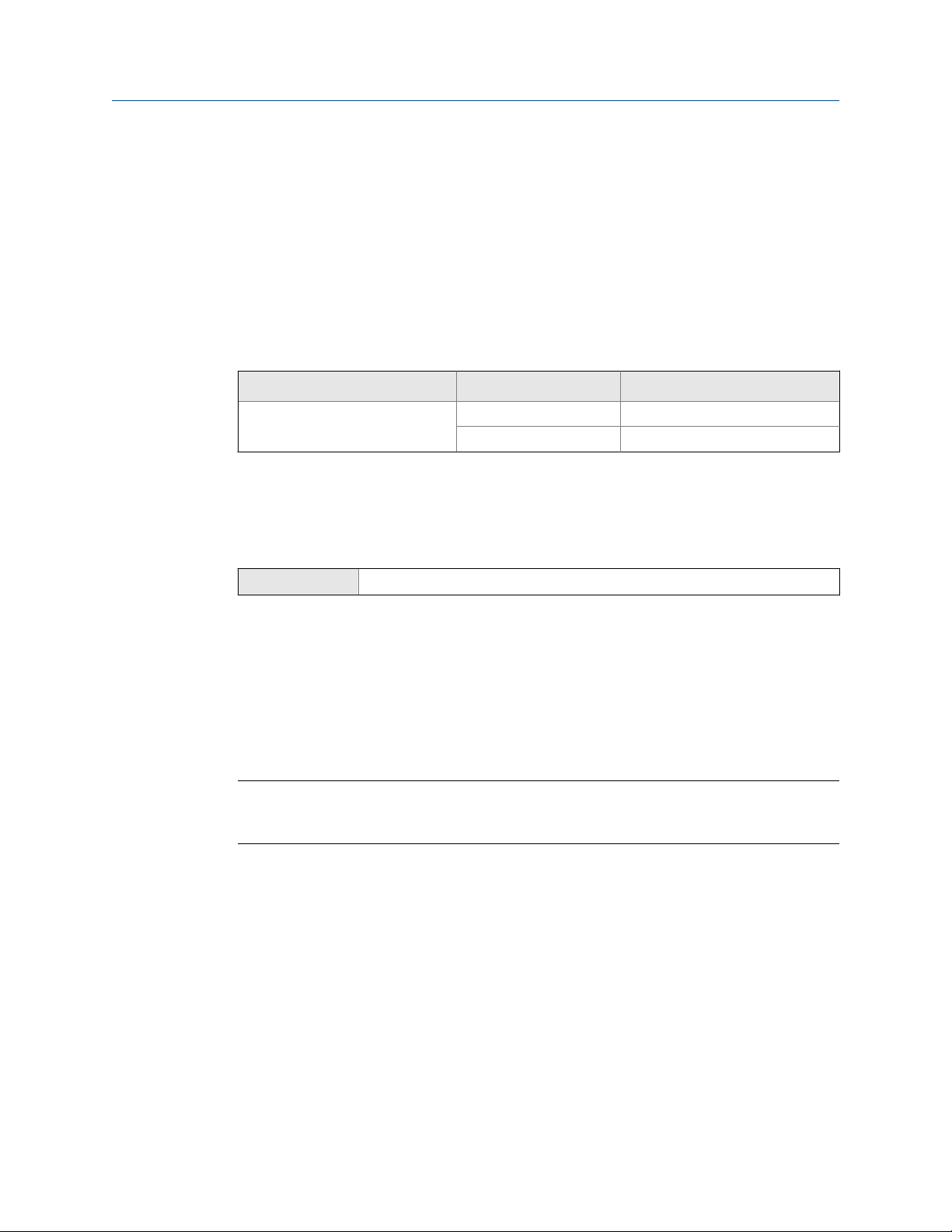
Model codes and device typesTable 1-1:
Model code Description I/O and communications
N Standard case • One dedicated service port/
P LNGS06S and LNGM10S
are paired
D With a dual core processor
Z Standalone sensor
I With enhanced core pro-
cessor for direct host connection with IS barrier
Modbus
• One dedicated RS-485 port/
Modbus
Configuration and Use Manual 3
Page 10

Before you begin
Model codes and device types (continued)Table 1-1:
Model code Description I/O and communications
N Spare sensor without elec-
tronics
1.3 Communications tools and protocols
You can use these communications tools and protocols to interface with the transmitter.
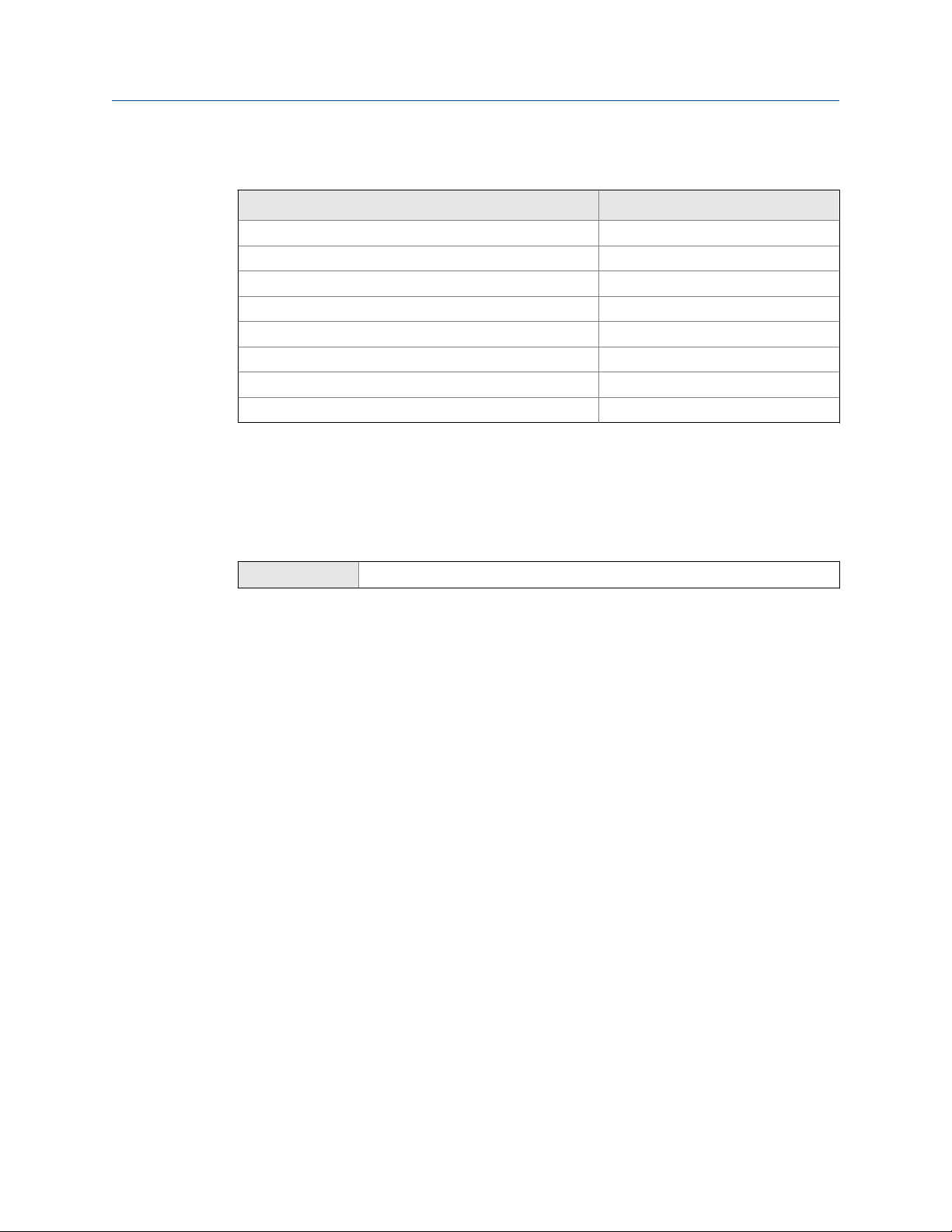
Communications tools, protocols, and related informationTable 1-2:
Communications tool Supported protocols Scope In this manual For more information
ProLink III • Modbus/RS-485
• Service port
Modbus host • Service port
• Modbus/RS-485
Complete configuration
and commissioning
Complete configuration
and commissioning
Basic user information.
See Appendix A.
None.
User manual
• Installed with soft-
ware
• Micro Motion user
documentation CD
• www.micromo‐
tion.com
Modbus Interface Tool
(MIT) — available at
www.micromotion.com
1.4 Additional documentation
Micro Motion provides additional documentation to support the installation and operation
of the meter.
Additional documentation and resourcesTable 1-3:
Topic Document
Transmitter installation
Product Data Sheet
Hazardous area installation
4 Micro Motion® LNG Series Meters
Micro Motion Liquified Natural Gas Dispenser Installation Manual
Micro Motion LNG Series Meters Product Data Sheet (PDS)
See the approval documentation shipped with the transmitter, or
download the appropriate documentation from the Micro Motion web
site at www.micromotion.com.
Page 11

All documentation resources are available on the Micro Motion web site at
www.micromotion.com.cn or on the Micro Motion user documentation DVD.
Before you begin
Configuration and Use Manual 5
Page 12

Before you begin
6 Micro Motion® LNG Series Meters
Page 13

2 Quick start
Topics covered in this chapter:
Power up the meter
•
Check meter status
•
Make a startup connection to the transmitter
•
Characterize the flowmeter (if required)
•
Verify mass flow measurement
•
Verify the zero
•
2.1 Power up the meter
The meter must be powered up for all configuration and commissioning tasks, or for
process measurement.
1. Ensure that all device covers and seals are closed.
Quick start
2.2
WARNING!
To prevent ignition of flammable or combustible atmospheres, ensure that all covers
and seals are tightly closed. For hazardous area installations, applying power while
housing covers are removed or loose can cause an explosion.
2. Turn on the electrical power at the power supply.
Postrequisites
Although the sensor is ready to measure shortly after power-up, the electronics can take
up to 10 minutes to reach thermal equilibrium. Therefore, if this is the initial startup, or if
power has been off long enough to allow components to reach ambient temperature,
allow the electronics equalize for approximately 10 minutes.
Check meter status
Check the meter for any error conditions that require user action or that affect
measurement accuracy.
1. Wait approximately 10 seconds for the power-up sequence to complete.
Immediately after power-up, the transmitter runs through diagnostic routines and
checks for error conditions.
2. Connect to the transmitter and check for active alerts.
Configuration and Use Manual 7
Page 14
Quick start
Related information
View and acknowledge status alerts
Status alerts, causes, and recommendations
2.3 Make a startup connection to the transmitter
Identify the connection type to use, and follow the instructions for that connection type in
the appropriate appendix.
Communications tool Connection type to use Instructions
ProLink III Service Port Section A.1.2
RS-485 port Section A.1.3
2.4 Characterize the flowmeter (if required)
ProLink III Device Tools > Calibration Data
Overview
Characterizing the flowmeter adjusts your transmitter to match the unique traits of the
sensor it is paired with. The characterization parameters (also called calibration
parameters) describe the sensor’s sensitivity to flow, density, and temperature.
Depending on your sensor type, different parameters are required. Values for your sensor
are provided by Micro Motion on the sensor tag or the calibration certificate.
Tip
If your meter was ordered as a unit, it has already been characterized at the factory. However, you
should still verify the characterization parameters.
Procedure
1. Specify Sensor Type.
• LNG-Series (LNGS06S, LNGM10S)
2. Set the flow characterization parameters. Be sure to include all decimal points.
• Set Flow Cal (Flow Calibration Factor).
3. Set the density characterization parameters.
• Set D1, D2, TC, K1, K2, and FD.
8 Micro Motion® LNG Series Meters
Page 15

2.4.1 Sensor tags
Tag on sensorsFigure 2-1:
Quick start
2.4.2 Density calibration parameters (D1, D2, K1, K2, FD, TC)
Density calibration parameters are typically on the sensor tag and the calibration
certificate.
2.5
2.6
Verify mass flow measurement
Check to see that the mass flow rate reported by the transmitter is accurate. You can use
any available method.
Connect to the transmitter with ProLink III and read the value for Mass Flow Rate in the
Process Variables panel.
Postrequisites
If the reported mass flow rate is not accurate:
• Check the characterization parameters.
• Review the troubleshooting suggestions for flow measurement issues.
Verify the zero
Verifying the zero helps you determine if the stored zero value is appropriate to your
installation, or if a field zero can improve measurement accuracy.
Configuration and Use Manual 9
Page 16

Quick start
The zero verification procedure analyzes the Live Zero value under conditions of zero flow,
and compares it to the Zero Stability range for the sensor. If the average Live Zero value is
within a reasonable range, the zero value stored in the transmitter is valid. Performing a
field calibration will not improve measurement accuracy.
2.6.1 Verify the zero using ProLink III
Verifying the zero helps you determine if the stored zero value is appropriate to your
installation, or if a field zero can improve measurement accuracy.
Important
In most cases, the factory zero is more accurate than the field zero. Do not zero the meter unless one
of the following is true:
• The zero is required by site procedures.
• The stored zero value fails the zero verification procedure.
Prerequisites
ProLink III v3.5, or a later release
Important
Do not verify the zero or zero the meter if a high-severity alert is active. Correct the problem, then
verify the zero or zero the meter. You may verify the zero or zero the meter if a low-severity alert is
active.
Procedure
1. Prepare the meter:
a. Allow the meter to warm up for at least 20 minutes after applying power.
b. Run the process fluid through the sensor until the sensor temperature reaches
the normal process operating temperature.
c. Stop flow through the sensor by shutting the downstream valve, and then the
upstream valve if available.
d. Verify that the sensor is blocked in, that flow has stopped, and that the sensor is
completely full of process fluid.
2. Choose Device Tools > Device Calibration > Zero Verification and Calibration > Verify Zero and
wait until the procedure completes.
3. If the zero verification procedure fails:
a. Confirm that the sensor is completely blocked in, that flow has stopped, and that
the sensor is completely full of process fluid.
b. Verify that the process fluid is not flashing or condensing, and that it does not
contain particles that can settle out.
c. Repeat the zero verification procedure.
d. If it fails again, zero the meter.
10 Micro Motion® LNG Series Meters
Page 17

Quick start
Postrequisites
Restore normal flow through the sensor by opening the valves.
2.6.2 Terminology used with zero verification and zero
calibration
Terminology used with zero verification and zero calibrationTable 2-1:
Term Definition
Zero In general, the offset required to synchronize the left pickoff and the right pickoff under
conditions of zero flow. Unit = microseconds.
Factory Zero The zero value obtained at the factory, under laboratory conditions.
Field Zero The zero value obtained by performing a zero calibration outside the factory.
Prior Zero The zero value stored in the transmitter at the time a field zero calibration is begun. May
be the factory zero or a previous field zero.
Manual Zero The zero value stored in the transmitter, typically obtained from a zero calibration proce-
dure. It may also be configured manually. Also called “mechanical zero” or “stored zero.”
Live Zero The real-time bidirectional mass flow rate with no flow damping or mass flow cutoff ap-
plied. An adaptive damping value is applied only when the mass flow rate changes dramatically over a very short interval. Unit = configured mass flow measurement unit.
Zero Stability A laboratory-derived value used to calculate the expected accuracy for a sensor. Under
laboratory conditions at zero flow, the average flow rate is expected to fall within the
range defined by the Zero Stability value (0 ± Zero Stability). Each sensor size and model
has a unique Zero Stability value. Statistically, 95% of all data points should fall within the
range defined by the Zero Stability value.
Zero Calibration The procedure used to determine the zero value.
Zero Time The time period over which the Zero Calibration procedure is performed. Unit = seconds.
Field Verification Zero A 3-minute running average of the Live Zero value, calculated by the transmitter. Unit =
configured mass flow measurement unit.
Zero Verification A procedure used to evaluate the stored zero and determine whether or not a field zero
can improve measurement accuracy.
Configuration and Use Manual 11
Page 18

Quick start
12 Micro Motion® LNG Series Meters
Page 19

Configuration and commissioning
Part II
Configuration and commissioning
Chapters covered in this part:
Introduction to configuration and commissioning
•
Configure process measurement
•
Configure device options and preferences
•
Integrate the meter with the control system
•
Complete the configuration
•
Configuration and Use Manual 13
Page 20

Configuration and commissioning
14 Micro Motion® LNG Series Meters
Page 21

Introduction to configuration and commissioning
3 Introduction to configuration and
commissioning
Topics covered in this chapter:
Default values and ranges
•
Disable write‐protection on the transmitter configuration
•
Restore the factory configuration
•
3.1 Default values and ranges
See Default values and ranges to view the default values and ranges for the most commonly
used parameters.
3.2 Disable write-protection on the transmitter configuration
ProLink III Device Tools > Configuration > Write-Protection
Overview
If the transmitter is write-protected, the configuration is locked and you must unlock it
before you can change any configuration parameters. By default, the transmitter is not
write-protected.
Tip
Write-protecting the transmitter prevents accidental changes to configuration. It does not prevent
normal operational use. You can always disable write-protection, perform any required configuration
changes, then re-enable write-protection.
3.3
Restore the factory configuration
ProLink III Device Tools > Configuration Transfer > Restore Factory Configuration
Overview
Restoring the factory configuration returns the transmitter to a known operational
configuration. This may be useful if you experience problems during configuration.
Configuration and Use Manual 15
Page 22

Introduction to configuration and commissioning
Tip
Restoring the factory configuration is not a common action. You may want to contact Micro Motion
to see if there is a preferred method to resolve any issues.
16 Micro Motion® LNG Series Meters
Page 23

Configure process measurement
4 Configure process measurement
Topics covered in this chapter:
Configure mass flow measurement
•
Configure volume flow measurement for liquid applications
•
Configure gas standard volume (GSV) flow measurement
•
Configure flow direction
•
Configure density measurement
•
Configure temperature measurement
•
4.1 Configure mass flow measurement
The mass flow measurement parameters control how mass flow is measured and reported.
The mass flow measurement parameters include:
Mass Flow Measurement Unit
•
Flow Damping
•
Mass Flow Cutoff
•
4.1.1
Configure Mass Flow Measurement Unit
ProLink III Device Tools > Configuration > Process Measurement > Flow
Overview
Mass Flow Measurement Unit specifies the unit of measure that will be used for the mass flow
rate. The unit used for mass total and mass inventory is derived from this unit.
Procedure
Set Mass Flow Measurement Unit to the unit you want to use.
The default setting for Mass Flow Measurement Unit is g/sec (grams per second).
Options for Mass Flow Measurement Unit
The transmitter provides a standard set of measurement units for Mass Flow Measurement
Unit, plus one user-defined special measurement unit. Different communications tools may
use different labels for the units.
Configuration and Use Manual 17
Page 24

Configure process measurement
Unit description ProLink III label
Grams per second
Grams per minute
Grams per hour
Kilograms per second
Kilograms per minute
Kilograms per hour
Kilograms per day
Metric tons per minute
Metric tons per hour
Metric tons per day
Pounds per second
Pounds per minute
Pounds per hour
Pounds per day
Short tons (2000 pounds) per minute
Short tons (2000 pounds) per hour
Short tons (2000 pounds) per day
Long tons (2240 pounds) per hour
Long tons (2240 pounds) per day
Special unit
Options for Mass Flow Measurement Unit Table 4-1:
g/sec
g/min
g/hr
kg/sec
kg/min
kg/hr
kg/day
mTon/min
mTon/hr
mTon/day
lbs/sec
lbs/min
lbs/hr
lbs/day
sTon/min
sTon/hr
sTon/day
lTon/hr
lTon/day
special
Define a special measurement unit for mass flow
ProLink III
Overview
A special measurement unit is a user-defined unit of measure that allows you to report
process data, totalizer data, and inventory data in a unit that is not available in the
transmitter. A special measurement unit is calculated from an existing measurement unit
using a conversion factor.
Procedure
1. Specify Base Mass Unit.
Base Mass Unit is the existing mass unit that the special unit will be based on.
2. Specify Base Time Unit.
18 Micro Motion® LNG Series Meters
Device Tools > Configuration > Process Measurement > Flow > Special Units
Page 25

Configure process measurement
Base Time Unit is the existing time unit that the special unit will be based on.
3. Calculate Mass Flow Conversion Factor as follows:
a. x base units = y special units
b. Mass Flow Conversion Factor = x ÷ y
The original mass flow rate value is divided by this value.
4. Enter Mass Flow Conversion Factor.
5. Set Mass Flow Label to the name you want to use for the mass flow unit.
6. Set Mass Total Label to the name you want to use for the mass total and mass
inventory unit.
The special measurement unit is stored in the transmitter. You can configure the
transmitter to use the special measurement unit at any time. You must use ProLink III to
select the special measurement unit.
Example: Defining a special measurement unit for mass flow
You want to measure mass flow in ounces per second (oz/sec).
4.1.2
1. Set Base Mass Unit to Pounds (lb).
2. Set Base Time Unit to Seconds (sec).
3. Calculate Mass Flow Conversion Factor:
a. 1 lb/sec = 16 oz/sec
b. Mass Flow Conversion Factor = 1 ÷ 16 = 0.0625
4. Set Mass Flow Conversion Factor to 0.0625.
5. Set Mass Flow Label to oz/sec.
6. Set Mass Total Label to oz.
Configure Flow Damping
ProLink III Device Tools > Configuration > Process Measurement > Flow
Overview
Damping is used to smooth out small, rapid fluctuations in process measurement. Damping
Value specifies the time period (in seconds) over which the transmitter will spread changes
in the process variable. At the end of the interval, the internal value will reflect 63% of the
change in the actual measured value.
Procedure
Set Flow Damping to the value you want to use.
The default value is 0.64 seconds. The range is 0 to 60 seconds.
Configuration and Use Manual 19
Page 26

Configure process measurement
Tips
• A high damping value makes the process variable appear smoother because the reported value
changes slowly.
• A low damping value makes the process variable appear more erratic because the reported value
changes more quickly.
• The combination of a high damping value and rapid, large changes in flow rate can result in
increased measurement error.
• Whenever the damping value is non-zero, the reported measurement will lag the actual
measurement because the reported value is being averaged over time.
• In general, lower damping values are preferable because there is less chance of data loss, and less
lag time between the actual measurement and the reported value.
• For gas applications, Micro Motion recommends setting Flow Damping to 2.56 or higher.
The value you enter is automatically rounded down to the nearest valid value. Valid
damping values are 0, 0.04, 0.08, 0.16, 0.32... 40.96.
Effect of Flow Damping on volume measurement
Flow Damping affects volume measurement for liquid volume data. Flow Damping also affects
volume measurement for gas standard volume data. The transmitter calculates volume
data from the damped mass flow data.
4.1.3
Configure Mass Flow Cutoff
ProLink III Device Tools > Configuration > Process Measurement > Flow
Overview
Mass Flow Cutoff specifies the lowest mass flow rate that will be reported as measured. All
mass flow rates below this cutoff will be reported as 0.
Procedure
Set Mass Flow Cutoff to the value you want to use.
The default value for Mass Flow Cutoff is 0.0 g/sec or a sensor-specific value set at the
factory. The recommended value is 0.5% of the nominal flow rate of the attached sensor.
See the sensor specifications. Do not leave Mass Flow Cutoff to 0.0 g/sec.
Effect of Mass Flow Cutoff on volume measurement
Mass Flow Cutoff does not affect volume measurement. Volume data is calculated from the
actual mass data rather than the reported value.
20 Micro Motion® LNG Series Meters
Page 27

Configure process measurement
4.2 Configure volume flow measurement for liquid applications
The volume flow measurement parameters control how liquid volume flow is measured
and reported.
The volume flow measurement parameters include:
Volume Flow Type
•
Volume Flow Measurement Unit
•
Volume Flow Cutoff
•
Restriction
You cannot implement both liquid volume flow and gas standard volume flow at the same time. You
must choose one or the other.
4.2.1 Configure Volume Flow Type for liquid applications
4.2.2
ProLink III Device Tools > Configuration > Process Measurement > Flow
Overview
Volume Flow Type controls whether liquid or gas standard volume flow measurement will be
used.
Restriction
If you are using the concentration measurement application, you must set Volume Flow Type to Liquid.
Gas standard volume measurement is incompatible with the concentration measurement
application.
Procedure
Set Volume Flow Type to Liquid.
Configure Volume Flow Measurement Unit for liquid applications
ProLink III Device Tools > Configuration > Process Measurement > Flow
Overview
Volume Flow Measurement Unit specifies the unit of measurement that will be displayed for the
volume flow rate. The unit used for the volume total and volume inventory is based on this
unit.
Configuration and Use Manual 21
Page 28

Configure process measurement
Prerequisites
Before you configure Volume Flow Measurement Unit, be sure that Volume Flow Type is set to
Liquid.
Procedure
Set Volume Flow Measurement Unit to the unit you want to use.
The default setting for Volume Flow Measurement Unit is l/sec (liters per second).
Options for Volume Flow Measurement Unit for liquid applications
The transmitter provides a standard set of measurement units for Volume Flow Measurement
Unit, plus one user-defined measurement unit. Different communications tools may use
different labels for the units.
Unit description ProLink III label
Cubic feet per second
Cubic feet per minute
Cubic feet per hour
Cubic feet per day
Cubic meters per second
Cubic meters per minute
Cubic meters per hour
Cubic meters per day
U.S. gallons per second
U.S. gallons per minute
U.S. gallons per hour
U.S. gallons per day
Million U.S. gallons per day
Liters per second
Liters per minute
Liters per hour
Million liters per day
Imperial gallons per second
Imperial gallons per minute
Imperial gallons per hour
Imperial gallons per day
Barrels per second
Options for Volume Flow Measurement Unit for liquid applicationsTable 4-2:
ft3/sec
ft3/min
ft3/hr
ft3/day
m3/sec
m3/min
m3/hr
m3/day
US gal/sec
US gal/min
US gal/hr
US gal/day
mil US gal/day
l/sec
l/min
l/hr
mil l/day
Imp gal/sec
Imp gal/min
Imp gal/hr
Imp gal/day
(1)
barrels/sec
22 Micro Motion® LNG Series Meters
Page 29
Configure process measurement
Options for Volume Flow Measurement Unit for liquid applications (continued)Table 4-2:
Unit description ProLink III label
Barrels per minute
Barrels per hour
Barrels per day
Beer barrels per second
Beer barrels per minute
Beer barrels per hour
Beer barrels per day
Special unit
(1) Unit based on oil barrels (42 U.S. gallons).
(2) Unit based on U.S. beer barrels (31 U.S. gallons).
(2)
barrels/min
barrels/hr
barrels/day
Beer barrels/sec
Beer barrels/min
Beer barrels/hr
Beer barrels/day
special
Define a special measurement unit for volume flow
ProLink III
Device Tools > Configuration > Process Measurement > Flow > Special Units
Overview
A special measurement unit is a user-defined unit of measure that allows you to report
process data, totalizer data, and inventory data in a unit that is not available in the
transmitter. A special measurement unit is calculated from an existing measurement unit
using a conversion factor.
Procedure
1. Specify Base Volume Unit.
Base Volume Unit is the existing volume unit that the special unit will be based on.
2. Specify Base Time Unit.
Base Time Unit is the existing time unit that the special unit will be based on.
3. Calculate Volume Flow Conversion Factor as follows:
a. x base units = y special units
b. Volume Flow Conversion Factor = x ÷ y
4. Enter Volume Flow Conversion Factor.
5. Enter Volume Flow Conversion Factor.
The original volume flow rate value is divided by this conversion factor.
6. Set Volume Flow Label to the name you want to use for the volume flow unit.
Configuration and Use Manual 23
Page 30

Configure process measurement
7. Set Volume Total Label to the name you want to use for the volume total and volume
The special measurement unit is stored in the transmitter. You can configure the
transmitter to use the special measurement unit at any time. You must use ProLink III to
select the special measurement unit.
Example: Defining a special measurement unit for volume flow
You want to measure volume flow in pints per second (pints/sec).
1. Set Base Volume Unit to Gallons (gal).
2. Set Base Time Unit to Seconds (sec).
3. Calculate the conversion factor:
4. Set Volume Flow Conversion Factor to 0.1250.
5. Set Volume Flow Label to pints/sec.
6. Set Volume Total Label to pints.
inventory unit.
a. 1 gal/sec = 8 pints/sec
b. Volume Flow Conversion Factor = 1 ÷ 8 = 0.1250
4.2.3 Configure Volume Flow Cutoff
ProLink III Device Tools > Configuration > Process Measurement > Flow
Overview
Volume Flow Cutoff specifies the lowest volume flow rate that will be reported as measured.
All volume flow rates below this cutoff are reported as 0.
Procedure
Set Volume Flow Cutoff to the value you want to use.
The default value for Volume Flow Cutoff is 0.0 l/sec (liters per second). The lower limit is 0.
The upper limit is the sensor’s flow calibration factor, in units of l/sec, multiplied by 0.2.
4.3
Configure gas standard volume (GSV) flow measurement
The gas standard volume (GSV) flow measurement parameters control how gas standard
volume flow is measured and reported.
The GSV flow measurement parameters include:
Volume Flow Type
•
24 Micro Motion® LNG Series Meters
Page 31

Configure process measurement
Standard Gas Density
•
Gas Standard Volume Flow Measurement Unit
•
Gas Standard Volume Flow Cutoff
•
Restriction
You cannot implement both liquid volume flow and gas standard volume flow at the same time. You
must choose one or the other.
4.3.1 Configure Volume Flow Type for gas applications
ProLink III Device Tools > Configuration > Process Measurement > Flow
Overview
Volume Flow Type controls whether liquid or gas standard volume flow measurement is
used.
4.3.2
Procedure
Set Volume Flow Type to Gas Standard Volume.
Configure Standard Gas Density
ProLink III Device Tools > Configuration > Process Measurement > Flow
Overview
The Standard Gas Density value is used to convert the measured flow data to the standard
reference values.
Prerequisites
Ensure that Density Measurement Unit is set to the measurement unit you want to use for
Standard Gas Density.
Procedure
Set Standard Gas Density to the standard reference density of the gas you are measuring.
Note
ProLink III provides a guided method that you can use to calculate the standard density of your gas, if
you do not know it.
Configuration and Use Manual 25
Page 32

Configure process measurement
4.3.3 Configure Gas Standard Volume Flow Measurement Unit
ProLink III Device Tools > Configuration > Process Measurement > Flow
Overview
Gas Standard Volume Flow Measurement Unitspecifies the unit of measure that will be displayed
for the gas standard volume flow rate. The measurement unit used for the gas standard
volume total and the gas standard volume inventory is derived from this unit.
Prerequisites
Before you configure Gas Standard Volume Flow Measurement Unit, be sure that Volume Flow Type
is set to Gas Standard Volume.
Procedure
Set Gas Standard Volume Flow Measurement Unit to the unit you want to use.
The default setting for Gas Standard Volume Flow Measurement Unit is SCFM (Standard Cubic
Feet per Minute).
Tip
If the measurement unit you want to use is not available, you can define a special measurement unit.
Options for Gas Standard Volume Flow Measurement Unit
The transmitter provides a standard set of measurement units for Gas Standard Volume Flow
Measurement Unit, plus one user-defined special measurement unit. Different
communications tools may use different labels for the units.
Options for
Unit description ProLink III label
Normal cubic meters per second
Normal cubic meters per minute
Normal cubic meters per hour
Normal cubic meters per day
Normal liter per second
Normal liter per minute
Normal liter per hour
Normal liter per day
Standard cubic feet per second
Standard cubic feet per minute
Gas Standard Volume Measurement Unit Table 4-3:
Nm3/sec
Nm3/sec
Nm3/hr
Nm3/day
NLPS
NLPM
NLPH
NLPD
SCFS
SCFM
26 Micro Motion® LNG Series Meters
Page 33

Configure process measurement
Options for Gas Standard Volume Measurement Unit (continued)Table 4-3:
Unit description ProLink III label
Standard cubic feet per hour
Standard cubic feet per day
Standard cubic meters per second
Standard cubic meters per minute
Standard cubic meters per hour
Standard cubic meters per day
Standard liter per second
Standard liter per minute
Standard liter per hour
Standard liter per day
Special measurement unit
SCFH
SCFD
Sm3/sec
Sm3/min
Sm3/hr
Sm3/day
SLPS
SLPM
SLPH
SLPD
special
Define a special measurement unit for gas standard volume flow
ProLink III
Overview
A special measurement unit is a user-defined unit of measure that allows you to report
process data, totalizer data, and inventory data in a unit that is not available in the
transmitter. A special measurement unit is calculated from an existing measurement unit
using a conversion factor.
Procedure
1. Specify Base Gas Standard Volume Unit.
Base Gas Standard Volume Unit is the existing gas standard volume unit that the special
unit will be based on.
2. Specify Base Time Unit.
Base Time Unit is the existing time unit that the special unit will be based on.
3. Calculate Gas Standard Volume Flow Conversion Factor as follows:
Device Tools > Configuration > Process Measurement > Flow > Special Units
a. x base units = y special units
b. Gas Standard Volume Flow Conversion Factor = x ÷ y
4. Enter the Gas Standard Volume Flow Conversion Factor.
The original gas standard volume flow value is divided by this conversion factor.
Configuration and Use Manual 27
Page 34

Configure process measurement
5. Set Gas Standard Volume Flow Label to the name you want to use for the gas standard
6. Set Gas Standard Volume Total Label to the name you want to use for the gas standard
The special measurement unit is stored in the transmitter. You can configure the
transmitter to use the special measurement unit at any time. You must use ProLink III to
select the special measurement unit.
Example: Defining a special measurement unit for gas standard volume flow
You want to measure gas standard volume flow in thousands of standard cubic feet per
minute.
1. Set Base Gas Standard Volume Unit to SCFM.
2. Set Base Time Unit to minutes (min).
3. Calculate the conversion factor:
volume flow unit.
volume total and gas standard volume inventory unit.
a. 1 thousands of standard cubic feet per minute = 1000 cubic feet per minute
b. Gas Standard Volume Flow Conversion Factor = 1 ÷ 1000 = 0.001
4.3.4
4. Set Gas Standard Volume Flow Conversion Factor to 0.001.
5. Set Gas Standard Volume Flow Label to KSCFM.
6. Set Gas Standard Volume Total Label to KSCF.
Configure Gas Standard Volume Flow Cutoff
ProLink III Device Tools > Configuration > Process Measurement > Flow
Overview
Gas Standard Volume Flow Cutoff specifies the lowest gas standard volume flow rate that will
reported as measured. All gas standard volume flow rates below this cutoff will be
reported as 0.
Procedure
Set Gas Standard Volume Flow Cutoff to the value you want to use.
The default value for Gas Standard Volume Flow Cutoff is 0.0. The lower limit is 0.0. There is no
upper limit.
4.4
28 Micro Motion® LNG Series Meters
Configure flow direction
ProLink III Device Tools > Configuration > Process Measurement > Flow
Page 35

Configure process measurement
Overview
Flow Direction controls how forward flow and reverse flow affect flow measurement and
reporting. You can configure two flow directions - one flow direction to map to the first
group of totals, and a second flow direction to map to the second group of totals. The
default flow directions are: Forward for the first group of totals, and Reverse for the second
group of totals.
Flow Direction is defined with respect to the flow arrow on the sensor:
• Forward flow (positive flow) moves in the direction of the flow arrow on the sensor.
• Reverse flow (negative flow) moves in the direction opposite to the flow arrow on
the sensor.
Tip
Micro Motion sensors are bidirectional. Measurement accuracy is not affected by actual flow
direction or the setting of the Flow Direction parameter.
Procedure
Set Flow Direction to the value you want to use.
4.4.1
You can configure two flow directions:
• The first flow direction is configured and applied to the first totals. The default setting is
Forward.
• The second flow direction is configured and applied to the second totals. The default
setting is Reverse.
Options for Flow Direction
Options for Flow Direction Table 4-4:
Flow direction setting from
ProLink III Relationship to Flow Direction arrow on sensor
Forward
Reverse
Absolute Value
Bidirectional
Negate Forward
Appropriate when the Flow Direction arrow is in the same
direction as the majority of flow.
Appropriate when the Flow Direction arrow is in the same
direction as the majority of flow.
Flow Direction arrow is not relevant.
Appropriate when both forward and reverse flow are expected, and forward flow will dominate, but the amount
of reverse flow will be significant.
Appropriate when the Flow Direction arrow is in the opposite direction from the majority of flow.
Configuration and Use Manual 29
Page 36

Configure process measurement
Flow direction setting from
Negate Bidirectional
Effect of Flow Direction on flow totals
Flow Direction affects how flow totals and inventories are calculated.
Options for Flow Direction (continued)Table 4-4:
ProLink III Relationship to Flow Direction arrow on sensor
Appropriate when both forward and reverse flow are expected, and reverse flow will dominate, but the amount of
forward flow will be significant.
Table 4-5:
Effect of the Flow Direction parameter and actual flow direction on flow
totals and inventories
Actual flow direction
Flow Direction setting
Forward
Reverse
Bidirectional
Absolute Value
Negate Forward
Negate Bidirectional
Forward Zero flow Reverse
Totals increase Totals do not change Totals do not change
Totals do not change Totals do not change Totals increase
Totals increase Totals do not change Totals decrease
Totals increase Totals do not change Totals increase
Totals do not change Totals do not change Totals increase
Totals decrease Totals do not change Totals increase
4.5 Configure density measurement
The density measurement parameters control how density is measured and reported.
Density measurement (along with mass measurement) is used to determine liquid volume
flow.
4.5.1
Configure Density Measurement Unit
ProLink III Device Tools > Configuration > Process Measurement > Density
Overview
Density Measurement Unit controls the measurement units that will be used in density
calculations and reporting.
30 Micro Motion® LNG Series Meters
Page 37

Configure process measurement
Procedure
Set Density Measurement Unit to the option you want to use.
The default setting for Density Measurement Unit is g/cm3 (grams per cubic centimeter).
Options for Density Measurement Unit
The transmitter provides a standard set of measurement units for Density Measurement Unit.
Different communications tools may use different labels.
Options for Density Measurement Unit Table 4-6:
Unit description ProLink III label
Specific gravity unit (not temperature-corrected)
Grams per cubic centimeter
Grams per liter
Grams per milliliter
Kilograms per liter
Kilograms per cubic meter
Pounds per U.S. gallon
Pounds per cubic foot
Pounds per cubic inch
API gravity
Short ton per cubic yard
SGU
g/cm3
g/l
g/ml
kg/l
kg/m3
lbs/Usgal
lbs/ft3
lbs/in3
degAPI
sT/yd3
4.5.2 Configure two-phase flow parameters
ProLink III Device Tools > Configuration > Process Measurement > Density
Overview
The two-phase flow parameters control how the transmitter detects and reports twophase flow (gas in a liquid process or liquid in a gas process).
Note
Two-phase flow is sometimes referred to as slug flow.
Procedure
1. Set Two-Phase Flow Low Limit to the lowest density value that is considered normal in
your process.
Configuration and Use Manual 31
Page 38

Configure process measurement
2. Set Two-Phase Flow High Limit to the highest density value that is considered normal in
Values below this will cause the transmitter to post Alert A105 ( Slug Flow.
Tip
Gas entrainment can cause your process density to drop temporarily. To reduce the
occurrence of two-phase flow alerts that are not significant to your process, set Two-Phase Flow
Low Limit slightly below your expected lowest process density.
You must enter Two-Phase Flow Low Limit in g/cm³, even if you configured another unit
for density measurement.
your process.
Values above this will cause the transmitter to post Alert A105 ( Slug Flow.
Tip
To reduce the occurrence of two-phase flow alerts that are not significant to your process, set
Two-Phase Flow High Limit slightly above your expected highest process density.
You must enter Two-Phase Flow High Limit in g/cm³, even if you configured another
unit for density measurement.
3. Set Two-Phase Flow Timeout to the number of seconds that the transmitter will wait for
a two-phase flow condition to clear before posting the alert.
The default value for Two-Phase Flow Timeout is 0.0 seconds, meaning that the alert
will be posted immediately. The range is 0.0 to 60.0 seconds.
Detecting and reporting two-phase flow
Two-phase flow (gas in a liquid process or liquid in a gas process) can cause a variety of
process control issues. By configuring the two-phase flow parameters appropriately for
your application, you can detect process conditions that require correction.
Tip
To decrease the occurrence of two-phase flow alerts, lower Two-Phase Flow Low Limit or raise Two-Phase
Flow High Limit.
A two-phase flow condition occurs whenever the measured density goes below Two-Phase
Flow Low Limit or above Two-Phase Flow High Limit. If this occurs:
• A two-phase flow alert is posted to the active alert log.
• All outputs that are configured to represent flow rate hold their last pre‐alert value
for the number of seconds configured in Two-Phase Flow Timeout.
If the two-phase flow condition clears before Two-Phase Flow Timeout expires:
• Outputs that represent flow rate revert to reporting actual flow.
32 Micro Motion® LNG Series Meters
Page 39

• The two-phase flow alert is deactivated, but remains in the active alert log until it is
acknowledged.
If the two-phase flow condition does not clear before Two-Phase Flow Timeout expires, the
outputs that represent flow rate report a flow rate of 0.
If Two-Phase Flow Timeout is set to 0.0 seconds, the outputs that represent flow rate will
report a flow rate of 0 as soon as two-phase flow is detected.
4.5.3 Configure density damping
ProLink III Device Tools > Configuration > Process Measurement > Density
Overview
Density Damping controls the amount of damping that will be applied to the line density
value.
Damping is used to smooth out small, rapid fluctuations in process measurement. Damping
Value specifies the time period (in seconds) over which the transmitter will spread changes
in the process variable. At the end of the interval, the internal value will reflect 63% of the
change in the actual measured value.
Configure process measurement
Procedure
Set Density Damping to the value you want to use.
The default value is 1.28 seconds. The range is 0 to 60 seconds.
Tips
• A high damping value makes the process variable appear smoother because the reported value
changes slowly.
• A low damping value makes the process variable appear more erratic because the reported value
changes more quickly.
• Whenever the damping value is non-zero, the reported measurement will lag the actual
measurement because the reported value is being averaged over time.
• In general, lower damping values are preferable because there is less chance of data loss, and less
lag time between the actual measurement and the reported value.
The value you enter is automatically rounded down to the nearest valid value. The valid
values for Density Damping are: 0, 0.04, 0.08, 0.16, 0.32... 40.96.
Effect of density damping on volume measurement
Density Damping affects liquid volume measurement. Liquid volume values are calculated
from the damped density value rather than the measured density value. Density Damping
does not affect gas standard volume measurement.
Configuration and Use Manual 33
Page 40

Configure process measurement
4.5.4 Configure Density Cutoff
ProLink III Device Tools > Configuration > Process Measurement > Density
Overview
Density Cutoff specifies the lowest density value that will be reported as measured. All
density values below this cutoff will be reported as 0.
Procedure
Set Density Cutoff to the value you want to use.
The default value for Density Cutoff is 0.2 g/cm³. The range is 0.0 g/cm³ to 0.5 g/cm³.
Effect of Density Cutoff on volume measurement
Density Cutoff affects liquid volume measurement. If the density value goes below Density
Cutoff, the volume flow rate is reported as 0. Density Cutoff does not affect gas standard
volume measurement. Gas standard volume values are always calculated from the value
configured for Standard Gas Density.
4.6 Configure temperature measurement
The temperature measurement parameters control how temperature data from the
sensor is reported.
4.6.1
Configure Temperature Measurement Unit
ProLink III Device Tools > Configuration > Process Measurement > Temperature
Overview
Temperature Measurement Unit specifies the unit that will be used for temperature
measurement.
Procedure
Set Temperature Measurement Unit to the option you want to use.
The default setting is Degrees Celsius.
Options for Temperature Measurement Unit
The transmitter provides a standard set of units for Temperature Measurement Unit. Different
communications tools may use different labels for the units.
34 Micro Motion® LNG Series Meters
Page 41

Options for Temperature Measurement Unit Table 4-7:
Unit description ProLink III
Degrees Celsius
Degrees Fahrenheit
Degrees Rankine
Kelvin
4.6.2 Configure Temperature Damping
ProLink III Device Tools > Configuration > Temperature
Overview
Temperature Damping controls the amount of damping that will be applied to the line
temperature value, when the on-board temperature data is used (RTD).
Configure process measurement
°C
°F
°R
°K
Damping is used to smooth out small, rapid fluctuations in process measurement. Damping
Value specifies the time period (in seconds) over which the transmitter will spread changes
in the process variable. At the end of the interval, the internal value will reflect 63% of the
change in the actual measured value.
Tip
Temperature Damping affects all process variables, compensations, and corrections that use
temperature data from the sensor.
Procedure
Enter the value you want to use for Temperature Damping.
The default value is 4.8 seconds. The range is 0.0 to 38.4 seconds.
Tips
• A high damping value makes the process variable appear smoother because the reported value
changes slowly.
• A low damping value makes the process variable appear more erratic because the reported value
changes more quickly.
• Whenever the damping value is non-zero, the reported measurement will lag the actual
measurement because the reported value is being averaged over time.
• In general, lower damping values are preferable because there is less chance of data loss, and less
lag time between the actual measurement and the reported value.
The value you enter is automatically rounded down to the nearest valid value. Valid values
for Temperature Damping are 0, 0.6, 1.2, 2.4, 4.8, … 38.4.
Configuration and Use Manual 35
Page 42

Configure process measurement
Effect of Temperature Damping on process measurement
Temperature Damping affects all processes and algorithms that use temperature data from
the internal sensor RTD.
Temperature compensation
Temperature compensation adjusts process measurement to compensate for the effect of
temperature on the sensor tubes.
36 Micro Motion® LNG Series Meters
Page 43

Configure device options and preferences
5 Configure device options and
preferences
Topics covered in this chapter:
Configure response time parameters
•
Configure alert handling
•
Configure informational parameters
•
5.1 Configure response time parameters
You can configure the rate at which process data is polled and process variables are
calculated.
Response time parameters include:
Update Rate
•
• Calculation Speed (Response Time)
5.1.1
Configure Calculation Speed (Response Time)
ProLink III Device Tools > Configuration > Process Measurement > Response > Calculation Speed
Overview
Calculation Speed is used to apply a different algorithm to the calculation of process variables
from the raw process data. Calculation Speed = Special produces faster and “noisier” response
to changes in the process.
Tip
You can use Calculation Speed = Special with either setting of Update Rate. The parameters control
different aspects of flowmeter processing.
Procedure
Set Calculation Speed as desired.
Option
Normal
Special
Description
Transmitter calculates process variables at the standard speed.
Transmitter calculates process variables at a faster speed.
Configuration and Use Manual 37
Page 44

Configure device options and preferences
5.2 Configure alert handling
The alert handling parameters control the transmitter’s response to process and device
conditions.
• Configure Fault Timeout (Section 5.2.1)
• Configure Status Alert Severity (Section 5.2.2)
5.2.1 Configure Fault Timeout
ProLink III Device Tools > Configuration > Fault Processing
Overview
Fault Timeout controls the delay before fault actions are performed.
Restriction
Fault Timeout is applied only to the following alerts (listed by Status Alert Code): A003, A004, A005,
A008, A016, A033. For all other alerts, fault actions are performed as soon as the alert is detected.
5.2.2
Procedure
Set Fault Timeout as desired.
The default value is 0 seconds. The range is 0 to 60 seconds.
If you set Fault Timeout to 0, fault actions are performed as soon as the alert condition is
detected.
The fault timeout period begins when the transmitter detects an alert condition. During
the fault timeout period, the transmitter continues to report its last valid measurements.
If the fault timeout period expires while the alert is still active, the fault actions are
performed. If the alert condition clears before the fault timeout expires, no fault actions
are performed.
Configure Status Alert Severity
ProLink III Device Tools > Configuration > Alert Severity
Overview
Use Status Alert Severity to control the fault actions that the transmitter performs when it
detects an alert condition.
38 Micro Motion® LNG Series Meters
Page 45

Configure device options and preferences
Restrictions
• For some alerts, Status Alert Severity is not configurable.
• For some alerts, Status Alert Severity can be set only to two of the three options.
Tip
Micro Motion recommends using the default settings for Status Alert Severity unless you have a specific
requirement to change them.
Procedure
1. Select a status alert.
2. For the selected status alert, set Status Alert Severity as desired.
Option
Fault
Informational
Ignore
Description
Actions when fault is detected:
• The alert is posted to the Alert List.
• Outputs go to the configured fault action (after Fault Timeout has expired, if
applicable).
• Digital communications go to the configured fault action (after Fault Timeout
has expired, if applicable).
• The status LED (if available) changes to red or yellow (depending on alert se-
verity).
Actions when alert clears:
• Outputs return to normal behavior.
• Digital communications return to normal behavior.
• The status LED (if available) returns to green and may or may not flash.
Actions when fault is detected:
• The alert is posted to the Alert List.
• The status LED (if available) changes to red or yellow (depending on alert se-
verity).
Actions when alert clears:
• The status LED (if available) returns to green and may or may not flash.
No action
Status alerts and options for Status Alert Severity
Status alerts and
Alert code Status message Default severity Notes Configurable?
A001 EEPROM Error
A002 RAM Error
A003 No Sensor Response
A004 Temperature Overrange
Status Alert Severity Table 5-1:
Fault
Fault
Fault
Fault
No
No
Yes
No
Configuration and Use Manual 39
Page 46

Configure device options and preferences
Status alerts and Status Alert Severity (continued)Table 5-1:
Alert code Status message Default severity Notes Configurable?
A005 Mass Flow Rate Overrange
A006 Characterization Required
A008 Density Overrange
A009 Transmitter Initializing/
Warming Up
A010 Calibration Failure
A011 Zero Calibration Failed:
Low
A012 Zero Calibration Failed:
High
A013 Zero Calibration Failed:
Unstable
A014 Transmitter Failure
A016 Sensor RTD Failure
A020 No Flow Cal Value
A021 Incorrect Sensor Type (K1)
A027 Security Breach
A030 Incorrect Board Type
A033 Insufficient Right/Left Pick-
off Signal
A102 Drive Overrange
A104 Calibration in Progress
A105 Slug Flow
A107 Power Reset Occurred
Fault
Fault
Fault
Fault
Fault
Fault
Fault
Fault
Fault
Fault
Fault
Fault
Fault
Fault
Fault
Informational
Informational
Informational
Informational
Applies only to flowmeters with the
enhanced core processor.
Can be set to either Informational or
Ignore, but cannot be set to Fault.
Normal transmitter behavior; occurs after every power cycle.
Yes
Yes
Yes
Yes
No
Yes
Yes
Yes
No
Yes
Yes
No
No
No
Yes
Yes
Yes
Yes
Yes
5.3 Configure informational parameters
The informational parameters can be used to identify or describe your meter. They are not
used in process measurement and they are not required.
5.3.1
40 Micro Motion® LNG Series Meters
Configure the sensor index
ProLink III Device Tools > Configuration > Informational Parameters > Sensor Index
Page 47

You can configure the sensor index only if the connection is through a service port. If the
connection is an RS-485 port, the sensor index is read-only, with each Modbus address
corresponding to a different sensor. In default, Modbus address 1 corresponds to sensor 1,
Modbus address 2 corresponds to sensor 2.
5.3.2 Configure the RTD cable length
ProLink III Device Tools > Configuration > Informational Parameters > Sensor > RTD1(2) Cable Length
Overview
Configure the RTD cable length if your 9-wire cable length is other than three meters.
Prerequisites
Verify that the sensor index is correct.
Procedure
Enter the cable length (unit:m) in the RTD 1(2) Cable Length field.
Configure device options and preferences
5.3.3
5.3.4
Related information
Configure the sensor index
Configure Sensor Serial Number
ProLink III Device Tools > Configuration > Informational Parameters > Sensor
Overview
Sensor Serial Number lets you store the serial number of the sensor component of your
flowmeter in transmitter memory. This parameter is not used in processing and is not
required.
Procedure
1. Obtain the sensor serial number from your sensor tag.
2. Enter the serial number in the Sensor Serial Number field.
Configure Sensor Material
ProLink III Device Tools > Configuration > Informational Parameters > Sensor
Configuration and Use Manual 41
Page 48

Configure device options and preferences
Overview
Sensor Material lets you store the type of material used for your sensor’s wetted parts in
transmitter memory. This parameter is not used in processing and is not required.
Procedure
1. Obtain the material used for your sensor’s wetted parts from the documents
shipped with your sensor, or from a code in the sensor model number.
To interpret the model number, refer to the product data sheet for your sensor.
2. Set Sensor Material to the appropriate option.
5.3.5 Configure Sensor Liner Material
ProLink III Device Tools > Configuration > Informational Parameters > Sensor
Overview
5.3.6
Sensor Liner Material lets you store the type of material used for your sensor liner in
transmitter memory. This parameter is not used in processing and is not required.
Procedure
1. Obtain your sensor’s liner material from the documents shipped with your sensor, or
from a code in the sensor model number.
To interpret the model number, refer to the product data sheet for your sensor.
2. Set Sensor Liner Material to the appropriate option.
Configure Sensor Flange Type
ProLink III Device Tools > Configuration > Informational Parameters > Sensor
Overview
Sensor Flange Type lets you store your sensor’s flange type in transmitter memory. This
parameter is not used in processing and is not required.
Procedure
1. Obtain your sensor’s flange type from the documents shipped with your sensor, or
from a code in the sensor model number.
To interpret the model number, refer to the product data sheet for your sensor.
2. Set Sensor Flange Type to the appropriate option.
42 Micro Motion® LNG Series Meters
Page 49

5.3.7 Configure Descriptor
ProLink III Device Tools > Configuration > Informational Parameters > Transmitter
Overview
Descriptor lets you store a description in transmitter memory. The description is not used in
processing and is not required.
Procedure
Enter a description for the transmitter or device
You can use up to 16 characters for the description.
5.3.8 Configure Message
Message lets you store a short message in transmitter memory. This parameter is not used
in processing and is not required.
Configure device options and preferences
5.3.9
Procedure
Enter a short message for the transmitter or device.
Your message can be up to 32 characters long.
Configure Date
ProLink III Device Tools > Configuration > Informational Parameters > Transmitter
Overview
Date lets you store a static date (not updated by the transmitter) in transmitter memory.
This parameter is not used in processing and is not required.
Procedure
Enter the date you want to use, in the form mm/dd/yyyy.
Tip
ProLink III provides a calendar tool to help you select the date.
Configuration and Use Manual 43
Page 50

Configure device options and preferences
44 Micro Motion® LNG Series Meters
Page 51

Integrate the meter with the control system
6 Integrate the meter with the control
system
Topics covered in this chapter:
Configure events
•
Configure digital communications
•
6.1 Configure events
An event occurs when the real-time value of a user-specified process variable moves past a
user-defined setpoint. Events are used to provide notification of process changes or to
perform specific transmitter actions if a process change occurs.
6.1.1 Configure an enhanced event
ProLink III Device Tools > Configuration > Events > Enhanced Events
Overview
An enhanced event is used to provide notification of process changes and, optionally, to
perform specific transmitter actions if the event occurs. An enhanced event occurs (is ON)
if the real-time value of a user-specified process variable moves above (HI) or below (LO) a
user-defined setpoint, or in range (IN) or out of range (OUT) with respect to two userdefined setpoints. You can define up to five enhanced events.
Procedure
1. Select the event that you want to configure.
2. Specify Event Type.
Options
HI
LO
IN
Description
x > A
The event occurs when the value of the assigned process variable (x) is
greater than the setpoint (Setpoint A), endpoint not included.
x < A
The event occurs when the value of the assigned process variable (x) is
less than the setpoint (Setpoint A), endpoint not included.
A ≤ x ≤ B
The event occurs when the value of the assigned process variable (x) is in
range, that is, between Setpoint A and Setpoint B, endpoints included.
Configuration and Use Manual 45
Page 52

Integrate the meter with the control system
Options Description
OUT
3. Assign a process variable to the event.
4. Set values for the required setpoints.
• For HI and LO events, set Setpoint A.
• For IN and OUT events, set Setpoint A and Setpoint B.
5. (Optional) Configure a discrete output to switch states in response to the event
status.
Options for Enhanced Event Action
Options for Enhanced Event Action Table 6-1:
x ≤ A or x ≥ B
The event occurs when the value of the assigned process variable (x) is
out of range, that is, less than Setpoint A or greater than Setpoint B, end-
points included.
Action ProLink III
None (default)
Start sensor zero
Start/stop all totalizers
Reset mass total
Reset volume total
Reset gas standard volume total
Reset all totals
None
Start Sensor Zero
Start/Stop All Totalization
Reset Mass Total
Reset Volume Total
Reset Gas Std Volume Total
Reset All Totals
6.2 Configure digital communications
The digital communications parameters control how the transmitter will communicate
using digital communications.
Your transmitter supports the following types of digital communications:
• Modbus RTU via the service port
• Modbus RTU via the RS-485 port
Note
The service port responds automatically to a wide range of connection requests. It is not
configurable.
46 Micro Motion® LNG Series Meters
Page 53

Integrate the meter with the control system
6.2.1 Configure Modbus/RS-485 communications
ProLink III Device Tools > Configuration > Communications > Communications (Modbus)
Overview
Modbus/RS-485 communications parameters control Modbus communication with the
transmitter's RS-485 terminals.
Modbus/RS-485 communications parameters include:
• Modbus Address (Slave Address)
Floating-Point Byte Order
•
Additional Communications Response Delay
•
Procedure
1. Set Modbus Address to a unique value on the network.
2. Set Floating-Point Byte Order to match the byte order used by your Modbus host.
Code
0
1
2
3
Byte order
1–2 3–4
3–4 1–2
2–1 4–3
4–3 2–1
See Table 6‐2for the bit structure of bytes 1, 2, 3, and 4.
Bit structure of floating-point bytesTable 6-2:
Byte Bits Definition
1 SEEEEEEE S=Sign
E=Exponent
2 EMMMMMMM E=Exponent
M=Mantissa
3 MMMMMMMM M=Mantissa
4 MMMMMMMM M=Mantissa
3. (Optional) Set Additional Communications Response Delay in delay units.
A delay unit is 2/3 of the time required to transmit one character, as calculated for
the port currently in use and the character transmission parameters. Valid values
range from 1 to 255.
Configuration and Use Manual 47
Page 54

Integrate the meter with the control system
Additional Communications Response Delay is used to synchronize Modbus
communications with hosts that operate at a slower speed than the transmitter. The
value specified here will be added to each response the transmitter sends to the
host.
Tip
Do not set Additional Communications Response Delayunless required by your Modbus host.
6.2.2 Configure RS-485 terminals
ProLink III Device Tools > Configuration > Communications > RS-485 Terminals
Overview
Modbus/RS-485 communication parameters control Modbus communication with the
transmitter's RS-485 terminals.
RS-485 terminal parameters include:
• Baud rate
• Parity
• Stop bits
Procedure
1. Set Baud Rate as appropriate for your network.
The following baud rates are supported:
• 4800
• 9600
• 19200
• 38400
2. Set Parity as appropriate for your network.
The following parity bits are supported:
• None
• Odd
• Even
3. Set Stop Bits as appropriate for your network.
The following stop bits are supported:
• 1
• 2
48 Micro Motion® LNG Series Meters
Page 55

Integrate the meter with the control system
6.2.3 Configure Digital Communications Fault Action
ProLink III Device Tools > Configuration > Fault Processing
Overview
Digital Communications Fault Actionspecifies the values that will be reported via digital
communications if the device encounters an internal fault condition.
Procedure
Set Digital Communications Fault Action as desired.
The default setting is None.
Options for Digital Communications Fault Action
Options for Digital Communications Fault Action Table 6-3:
Label
Upscale Upscale
Downscale Downscale
Zero IntZero-All 0
None
None (default) • All process variables are reported as measured.
DescriptionProLink III
• Process variable values indicate that the value is great-
er than the upper sensor limit.
• Totalizers stop incrementing.
• Process variable values indicate that the value is lower
than the lower sensor limit.
• Totalizers stop incrementing.
• Flow rate variables go to the value that represents a
flow rate of 0 (zero).
• Density is reported as 0.
• Temperature is reported as 0 °C , or the equivalent if
other units are used (e.g., 32 °F .
• Drive gain is reported as measured.
• Totalizers stop incrementing.
• Totalizers increment if they are running.
Configuration and Use Manual 49
Page 56

Integrate the meter with the control system
50 Micro Motion® LNG Series Meters
Page 57

7 Complete the configuration
Topics covered in this chapter:
Back up transmitter configuration
•
Enable write‐protection on the transmitter configuration
•
7.1 Back up transmitter configuration
ProLink III provides a configuration upload/download function which allows you to save
configuration sets to your PC. This allows you to back up and restore your transmitter
configuration. This is also a convenient way to replicate a configuration across multiple
devices.
Restriction
This function is not available with any other communications tools.
Complete the configuration
7.2
Procedure
To back up the transmitter configuration using ProLink III:
1. Choose Device Tools > Configuration Transfer > Save or Load Configuration Data.
2. In the Configuration groupbox, select the configuration data you want to save.
3. Click Save, then specify a file name and location on your computer.
4. Click Start Save.
The backup file is saved to the specified name and location. It is saved as a text file and can
be read using any text editor.
Enable write-protection on the transmitter configuration
ProLink III Device Tools > Configuration > Write-Protection
Overview
If the transmitter is write-protected, the configuration is locked and nobody can change it
until it is unlocked. This prevents accidental or unauthorized changes to the transmitter
configuration parameters.
Configuration and Use Manual 51
Page 58

Complete the configuration
52 Micro Motion® LNG Series Meters
Page 59

Operations, maintenance, and troubleshooting
Part III
Operations, maintenance, and
troubleshooting
Chapters covered in this part:
Transmitter operation
•
Measurement support
•
Troubleshooting
•
Configuration and Use Manual 53
Page 60

Operations, maintenance, and troubleshooting
54 Micro Motion® LNG Series Meters
Page 61

8 Transmitter operation
Topics covered in this chapter:
Custody transfer
•
Record the process variables
•
View process variables
•
View transmitter status using the status LED
•
View and acknowledge status alerts
•
Read totalizer and inventory values
•
Start and stop totalizers and inventories
•
Reset totalizers
•
Reset inventories
•
Transmitter operation
8.1 Custody transfer
A custody transfer switch that controls custody transfer status is located inside the dual
processor.
When the switch is off
• The transmitter works under custody transfer unsecured mode
• The transmitter can be configured
• The status LED is red
• The A027 Security Breach alert is active
When the switch is on:
• The transmitter works under custody transfer secured mode
• The transmitter cannot be configured
• Unless there are alarms, the status LED is green
8.2
Record the process variables
Micro Motion suggests that you make a record of specific process variable measurements,
including the acceptable range of measurements, under normal operating conditions. This
data will help you recognize when the process or diagnostic variables are unusually high or
low, and may help you diagnose and troubleshoot application issues.
Procedure
Record the following process and diagnostic variables, under normal operating conditions.
Configuration and Use Manual 55
Page 62

Transmitter operation
Measurement
Variable
Flow rate
Density
Temperature
Tube frequency
Pickoff voltage
Drive gain
Typical average Typical high Typical low
8.3 View process variables
ProLink III View the desired variable on the main screen under Process Variables. See Section 8.3.1for
more information.
Overview
Process variables provide information about the state of the process fluid, such as flow
rate, density, and temperature, as well as running totals. Process variables can also provide
data about flowmeter operation, such as drive gain and pickoff voltage. This information
can be used to understand and troubleshoot your process.
8.3.1
8.4
• View process variables and other data using ProLink III (Section 8.3.1)
View process variables and other data using ProLink III
Monitor process variables, diagnostic variables, and other data to maintain process quality.
ProLink III automatically displays process variables, diagnostic variables, and other data on
the main screen.
Tip
ProLink III allows you to choose the process variables that appear on the main screen. You can also
choose whether to view data in Analog Gauge view or digital view, and you can customize the gauge
settings. For more information, see the ProLink III user manual.
View transmitter status using the status LED
The status LED shows the current alert condition of the transmitter. The status LED is
located on the face of the transmitter.
Observe the status LED.
56 Micro Motion® LNG Series Meters
Page 63

Transmitter operation
To interpret the status LED, see the following table.
Restriction
If LED Blinking is disabled, the status LED will flash only during calibration. It will not flash to indicate
an unacknowledged alarm.
Status LED statesTable 8-1:
LED behavior Alarm condition Description
Solid green No alarm Normal operation
Solid yellow Active low-severity alarm Alarm has been acknowledged
Flashing yellow
Solid red Active high-severity alarm Alarm has been acknowledged
Flashing red Active high-severity alarm Alarm has not been acknowledged
Active low-severity alarm Alarm has not been acknowledged
8.5 View and acknowledge status alerts
The transmitter posts status alerts whenever a process variable exceeds its defined limits
or the transmitter detects a fault condition. You can view active alerts, and you can
acknowledge alerts. Acknowledging alerts is not required.
• View and acknowledge alerts using ProLink III (Section 8.5.1)
8.5.1
View and acknowledge alerts using ProLink III
You can view a list containing all alerts that are active, or inactive but unacknowledged.
From this list, you can acknowledge individual alerts or choose to acknowledge all alerts at
once.
1. View alerts on the ProLink III main screen under Alerts.
All active or unacknowledged alerts are listed, and displayed according to the
following categories:
Category
Failed: Fix Now
Maintenance: Fix Soon
Advisory: Informational
Description
A meter failure has occurred and must be addressed immediately.
A condition has occurred that can be fixed at a later time.
A condition has occurred, but requires no maintenance from you.
Configuration and Use Manual 57
Page 64

Transmitter operation
Notes
• All fault alerts are displayed in the Failed: Fix Now category.
• All information alerts are displayed in either the Maintenance: Fix Soon category or the
Advisory: Informational category. The category assignment is hard-coded.
• The transmitter automatically filters out alerts with Alert Severity set to Ignore.
2. To acknowledge a single alert, check the Ack checkbox for that alert. To
acknowledge all alerts at once, click Ack All.
Postrequisites
• To clear the following alerts, you must correct the problem, acknowledge the alert,
then power-cycle the transmitter: A001, A002, A010, A011, A012, A013, A029.
• For all other alerts:
- If the alert is inactive when it is acknowledged, it will be removed from the list.
- If the alert is active when it is acknowledged, it will be removed from the list
when the alert condition clears.
Related information
Alert data in transmitter memory
8.5.2 Alert data in transmitter memory
The transmitter maintains three sets of data for every alert that is posted.
For each alert occurrence, the following three sets of data are maintained in transmitter
memory:
• Alert List
• Alert Statistics
• Recent Alerts
Alert data in transmitter memoryTable 8-2:
Transmitter action if condition occurs
Alert data structure
Alert List As determined by the alert status bits, a list of:
Alert Statistics One record for each alert (by alert number)
Contents Clearing
Cleared and regenerated with every transmit-
• All currently active alerts
• All previously active alerts that have not
been acknowledged
that has occurred since the last master reset.
Each record contains:
• A count of the number of occurrences
• Timestamps for the most recent posting
and clearing
ter power cycle
Not cleared; maintained across transmitter
power cycles
58 Micro Motion® LNG Series Meters
Page 65

Transmitter operation
Alert data in transmitter memory (continued)Table 8-2:
Transmitter action if condition occurs
Alert data structure
Recent Alerts 50 most recent alert postings or alert clearings Not cleared; maintained across transmitter
Contents Clearing
power cycles
8.6 Read totalizer and inventory values
ProLink III View the desired variable on the main screen under Process Variables.
Overview
Totalizers keep track of the total amount of mass or volume measured by the transmitter
since the last totalizer reset. Inventories keep track of the total amount of mass or volume
measured by the transmitter since the last inventory reset.
Tip
You can use the inventories to keep a running total of mass or volume across multiple totalizer
resets.
8.7
Start and stop totalizers and inventories
ProLink III Device Tools > Totalizer Control > Totalizer and Inventories > Start All Totals
Device Tools > Totalizer Control > Totalizer and Inventories > Stop All Totals
Overview
When you start a totalizer, it tracks process measurement. In a typical application, its value
increases with flow. When you stop a totalizer, it stops tracking process measurement and
its value does not change with flow. Inventories are started and stopped automatically,
when totalizers are started and stopped.
Important
Totalizers and inventories are started or stopped as a group. When you start any totalizer, all other
totalizers and all inventories are started simultaneously.When you stop any totalizer, all other
totalizers and all inventories are stopped simultaneously. You cannot start or stop inventories
directly.
Configuration and Use Manual 59
Page 66

Transmitter operation
8.8 Reset totalizers
ProLink III Device Tools > Totalizer Control > Totalizer and Inventories > Reset Mass Total
Device Tools > Totalizer Control > Totalizer and Inventories > Reset Volume Total
Device Tools > Totalizer Control > Totalizer and Inventories > Reset Gas Total
Device Tools > Totalizer Control > Totalizer and Inventories > Reset All Totals
Overview
When you reset a totalizer, the transmitter sets its value to 0. It does not matter whether
the totalizer is started or stopped. If the totalizer is started, it continues to track process
measurement.
Tip
When you reset a single totalizer, the values of other totalizers are not reset. Inventory values are not
reset.
8.9 Reset inventories
ProLink III Device Tools > Totalizer Control > Totalizer and Inventories > Reset Mass Inventory
Device Tools > Totalizer Control > Totalizer and Inventories > Reset Volume Inventory
Device Tools > Totalizer Control > Totalizer and Inventories > Reset Gas Inventory
Device Tools > Totalizer Control > Totalizer and Inventories > Reset All Inventories
Overview
When you reset an inventory, the transmitter sets its value to 0. It does not matter
whether the inventory is started or stopped. If the inventory is started, it continues to track
process measurement.
Tip
When you reset a single inventory, the values of other inventories are not reset. Totalizer values are
not reset.
Prerequisites
To use ProLink III to reset the inventories, the feature must be enabled.
• To enable inventory reset in ProLink III:
1. Choose Tools > Options.
2. Select Reset Inventories from ProLink III.
60 Micro Motion® LNG Series Meters
Page 67

9 Measurement support
Topics covered in this chapter:
Options for measurement support
•
Zero the meter
•
Validate the meter
•
Perform a (standard) D1 and D2 density calibration
•
9.1 Options for measurement support
Micro Motion provides several measurement support procedures to help you evaluate and
maintain your flowmeter's accuracy.
The following methods are available:
• Meter validation compares flowmeter measurements reported by the transmitter to
an external measurement standard. Meter validation requires one data point.
• Calibration establishes the relationship between a process variable and the signal
produced at the sensor. You can calibrate the flowmeter for zero, density, and
temperature. Density and temperature calibration require two data points (low and
high) and an external measurement for each.
Measurement support
9.2
9.2.1
Tips
• To prove the meter against a regulatory standard, or to correct measurement error, use
meter validation and meter factors.
• Before performing a field calibration, contact Micro Motion to see if there is an alternative. In
many cases, field calibrations have a negative effect on measurement accuracy.
Zero the meter
Zeroing the meter establishes a baseline for process measurement by analyzing the
sensor's output when there is no flow through the sensor tubes.
Zero the meter using ProLink III
Zeroing the meter establishes a baseline for process measurement by analyzing the
sensor's output when there is no flow through the sensor tubes.
Important
In most cases, the factory zero is more accurate than the field zero. Do not zero the meter unless one
of the following is true:
• The zero is required by site procedures.
Configuration and Use Manual 61
Page 68

Measurement support
• The stored zero value fails the zero verification procedure.
Prerequisites
Before performing a field zero, execute the Zero Verification procedure to see whether or
not a field zero can improve measurement accuracy.
Important
Do not verify the zero or zero the meter if a high-severity alert is active. Correct the problem, then
verify the zero or zero the meter. You may verify the zero or zero the meter if a low-severity alert is
active.
Procedure
1. Prepare the meter:
a. Allow the meter to warm up for at least 20 minutes after applying power.
b. Run the process fluid through the sensor until the sensor temperature reaches
the normal process operating temperature.
c. Stop flow through the sensor by shutting the downstream valve, and then the
upstream valve if available.
d. Verify that the sensor is blocked in, that flow has stopped, and that the sensor is
completely full of process fluid.
e. Verify that the process fluid is not flashing or condensing, and that it does not
contain particles that can settle out.
f. Remove or reduce sources of electromechanical noise if appropriate.
g. Observe the drive gain, temperature, and density readings. If they are stable,
check the Live Zero or Field Verification Zero value. If the average value is close to 0,
you should not need to zero the meter.
2. Choose Device Tools > Calibration > Zero Verification and Calibration.
3. Modify Zero Time, if desired.
Zero Time controls the amount of time the transmitter takes to determine its zeroflow reference point. The default Zero Time is 20 seconds. For most applications, the
default Zero Time is appropriate.
4. Click Calibrate Zero.
The Calibration in Progress message is displayed. When the calibration is
complete:
• If the zero procedure was successful, a Calibration Success message and a
new zero value are displayed.
• If the zero procedure failed, a Calibration Failed message is displayed.
Postrequisites
Restore normal flow through the sensor by opening the valves.
62 Micro Motion® LNG Series Meters
Page 69

Need help? If the zero fails:
• Ensure that there is no flow through the sensor, then retry.
• Set Zero Time to a lower value, then retry.
• If you want to return the flowmeter to operation using a previous zero value:
- To restore the zero value set at the factory: Device Tools > Zero Verification and Calibration >
Calibrate Zero > Restore Factory Zero. This function requires the enhanced core processor.
- To restore the most recent valid value from transmitter memory: Device Tools > Zero
Verification and Calibration > Calibrate Zero > Restore Prior Zero. Restore Prior Zero is available only
while the Flow Calibration window is open. If you close the Flow Calibration window, you
will no longer be able to restore the prior zero.
Restriction
Restore the factory zero only if your meter was purchased as a unit, it was zeroed at the factory, and
you are using the original components.
9.2.2 Record the zeros
Measurement support
9.3
ProLink III Device Tools > Diagnostics > Zero Log
Overview
Record the zero values from the zero log.
The zero log stores the last twenty zero values for each sensor, including the time stamp,
maximum/minumum temperature, maximum/minimum density, and maximum/
minimum drive gain.
Note
The maximum and minimum values are the values stored while the meter was calibrating each zero.
Validate the meter
ProLink III Device Tools > Configuration > Process Measurement > Flow
Device Tools > Configuration > Process Measurement > Density
Overview
Meter validation compares flowmeter measurements reported by the transmitter to an
external measurement standard. If the transmitter value for mass flow, volume flow, or
density measurement is significantly different from the external measurement standard,
you may want to adjust the corresponding meter factor. The flowmeter’s actual
measurement is multiplied by the meter factor, and the resulting value is reported and
used in further processing.
Configuration and Use Manual 63
Page 70

NewMeterFactor = ConfiguredMeterFactor
ReferenceMeasurement
FlowmeterMeasurement
MeterFactor
MassFlow
= 1
250
250.27
= 0.9989
Measurement support
Prerequisites
Identify the meter factor(s) that you will calculate and set. You may set any combination of
the three meter factors: mass flow, volume flow, and density. Note that all three meter
factors are independent:
• The meter factor for mass flow affects only the value reported for mass flow.
• The meter factor for density affects only the value reported for density.
Important
To adjust volume flow, you must set the meter factor for volume flow. Setting a meter factor for
mass flow and a meter factor for density will not produce the desired result. The volume flow
calculations are based on original mass flow and density values, before the corresponding meter
factors have been applied.
If you plan to calculate the meter factor for volume flow, be aware that validating volume
in the field may be expensive, and the procedure may be hazardous for some process
fluids. Therefore, because volume is inversely proportional to density, an alternative to
direct measurement is to calculate the meter factor for volume flow from the meter factor
for density. See Section 9.3.1 for instructions on this method.
Obtain a reference device (external measurement device) for the appropriate process
variable.
Important
For good results, the reference device must be highly accurate.
Procedure
1. Determine the meter factor as follows:
a. Use the flowmeter to take a sample measurement.
b. Measure the same sample using the reference device.
c. Calculate the meter factor using the following formula:
2. Ensure that the calculated meter factor is between 0.8 and 1.2, inclusive. If the
meter factor is outside these limits, contact Micro Motion customer service.
3. Configure the meter factor in the transmitter.
Example: Calculating the meter factor for mass flow
The flowmeter is installed and validated for the first time. The mass flow measurement
from the transmitter is 250.27 lb. The mass flow measurement from the reference device
is 250 lb. The mass flow meter factor is calculated as follows:
64 Micro Motion® LNG Series Meters
Page 71

MeterFactor
MassFlow
= 0.9989
250.25
250.07
= 0.9996
MeterFactor
Volume
=
1
MeterFactor
Density
MeterFactor
Volume
= ConfiguredMeterFactor
Density
Density
Flowmeter
Density
Reference Device
Measurement support
The first meter factor for mass flow is 0.9989.
One year later, the flowmeter is validated again. The mass flow measurement from the
transmitter is 250.07 lb. The mass flow measurement from the reference device is
250.25 lb. The new mass flow meter factor is calculated as follows:
The new meter factor for mass flow is 0.9996.
9.3.1 Alternate method for calculating the meter factor for volume flow
The alternate method for calculating the meter factor for volume flow is used to avoid the
difficulties that may be associated with the standard method.
This alternate method is based on the fact that volume is inversely proportional to density.
It provides partial correction of the volume flow measurement by adjusting for the portion
of the total offset that is caused by the density measurement offset. Use this method only
when a volume flow reference is not available, but a density reference is available.
9.4
Procedure
1. Calculate the meter factor for density, using the standard method (see Section 9.3).
2. Calculate the meter factor for volume flow from the meter factor for density:
Note
The following equation is mathematically equivalent to the first equation. You may use
whichever version you prefer.
3. Ensure that the calculated meter factor is between 0.8 and 1.2, inclusive. If the
meter factor is outside these limits, contact Micro Motion customer service.
4. Configure the meter factor for volume flow in the transmitter.
Perform a (standard) D1 and D2 density calibration
Density calibration establishes the relationship between the density of the calibration
fluids and the signal produced at the sensor. Density calibration includes the calibration of
the D1 (low-density) and D2 (high-density) calibration points.
Configuration and Use Manual 65
Page 72

Measurement support
Important
Micro Motion flowmeters are calibrated at the factory, and normally do not need to be calibrated in
the field. Calibrate the flowmeter only if you must do so to meet regulatory requirements. Contact
Micro Motion before calibrating the flowmeter.
Tip
Micro Motion recommends using meter validation and meter factors, rather than calibration, to
prove the meter against a regulatory standard or to correct measurement error.
9.4.1 Perform a D1 and D2 density calibration using ProLink III
Prerequisites
• During density calibration, the sensor must be completely filled with the calibration
fluid, and flow through the sensor must be at the lowest rate allowed by your
application. This is usually accomplished by closing the shutoff valve downstream
from the sensor, then filling the sensor with the appropriate fluid.
• D1 and D2 density calibration require a D1 (low-density) fluid and a D2 (high-
density) fluid. You may use air and water.
• The calibrations must be performed without interruption, in the order shown. Make
sure that you are prepared to complete the process without interruption.
• Before performing the calibration, record your current calibration parameters. You
can do this by saving the current configuration to a file on the PC. If the calibration
fails, restore the known values.
Procedure
See the following figure.
66 Micro Motion® LNG Series Meters
Page 73

Measurement support
D1 and D2 density calibration using ProLink IIIFigure 9-1:
Configuration and Use Manual 67
Page 74

Measurement support
68 Micro Motion® LNG Series Meters
Page 75

10 Troubleshooting
Topics covered in this chapter:
Status LED states
•
Status alerts, causes, and recommendations
•
Flow measurement problems
•
Density measurement problems
•
Temperature measurement problems
•
Check power supply wiring
•
Check grounding
•
Check for radio frequency interference (RFI)
•
Check for two‐phase flow (slug flow)
•
Check the drive gain
•
Check the pickoff voltage
•
Check for internal electrical problems
•
Troubleshooting
10.1 Status LED states
The status LED on the transmitter indicates whether or not alerts are active. If alerts are
active, view the alert list to identify the alerts, then take appropriate action to correct the
alert condition.
Status LED statesTable 10-1:
Condition LED Blinking parameter LED behavior
Normal operation (no alert) N/A Solid green
Unacknowledged corrected condition (no alert) Enabled Flashing green
Acknowledged low-severity alert (outputs continue to report process data)
Unacknowledged low-severity alert (outputs
continue to report process data)
Acknowledged high-severity alert (outputs in
fault)
Unacknowledged high-severity alert (outputs in
fault)
Disabled Solid green
N/A Solid yellow
Enabled Flashing yellow
Disabled Solid yellow
N/A Solid red
Enabled Flashing red
Disabled Solid red
Configuration and Use Manual 69
Page 76

Troubleshooting
10.2 Status alerts, causes, and recommendations
Alert number Alert title Possible cause Recommended actions
A001 EEPROM Error The transmitter has detected a
problem communicating with the
sensor.
A002 RAM Error The transmitter has detected a
problem communicating with the
sensor.
A003 No Sensor Response The transmitter is not receiving one
or more basic electrical signals from
the sensor.
A004 Temperature Over-
range
A005 Mass Flow Rate
Overrange
A006 Characterization Re-
quired
The RTD resistance is out of range
for the sensor.
The measured flow rate is greater
than the maximum flow rate of the
sensor (ΔT greater than 200 µs).
Calibration factors have not been
entered, or the sensor type is incorrect, or the calibration factors are
incorrect for the sensor type.
• Cycle power to the meter.
• Replace the core processor.
• Contact Micro Motion.
• Cycle power to the meter.
• Replace the core processor.
• Contact Micro Motion.
• Check the drive gain and the pickoff
voltage.
• Check the wiring between the sensor
and the transmitter.
• Verify that internal wiring is secure and
that there are no internal electrical
problems.
• Check the integrity of the sensor tubes.
• Check your process conditions against
the values reported by the device.
• Verify temperature characterization or
calibration parameters.
• Verify that internal wiring is secure and
that there are no internal electrical
problems.
• Check the wiring between the sensor
and the transmitter.
• Contact Micro Motion.
• If other alerts are present, resolve those
alert conditions first. If the current alert
persists, continue with the recommended actions.
• Check your process conditions against
the values reported by the device.
• Check for two-phase flow.
• Verify all of the characterization or cali-
bration parameters. See the sensor tag
or the calibration sheet for your meter.
• Verify the setting of the Sensor Type pa-
rameter.
• If Sensor Type=Curved Tube, ensure that
no parameters specific to Straight Tube
have been set.
• Verify that internal wiring is secure and
that there are no internal electrical
problems.
• Replace the core processor.
• Contact Micro Motion.
70 Micro Motion® LNG Series Meters
Page 77

Alert number Alert title Possible cause Recommended actions
A008 Density Overrange The line density is greater than
10 g/cm3 (10000 kg/m3 .
A009 Transmitter Initializ-
ing/Warming Up
A010 Calibration Failure Many possible causes.
Transmitter is in power-up mode. • Allow the meter to complete its power-
This alert will not clear until you cycle power to the meter.
• If other alerts are present, resolve those
alert conditions first. If the current alert
persists, continue with the recommended actions.
• Check for air in the flow tubes, tubes
not filled, foreign material in the tubes,
coating in the tubes, or other process
problems.
• Check for two-phase flow.
• Verify all of the characterization or cali-
bration parameters. See the sensor tag
or the calibration sheet for your meter.
• Check the drive gain and the pickoff
voltage.
• Perform Smart Meter Verification.
• Perform density calibration.
• Contact Micro Motion.
up sequence. The alert should clear automatically.
• If other alerts are present, resolve those
alert conditions first. If the current alert
persists, continue with the recommended actions.
• Verify that the tubes are full of process
fluid.
• Check the wiring between the sensor
and the transmitter.
• Verify that the transmitter is receiving
sufficient power.
- If it is not, correct the problem and
cycle power to the meter.
- If it is, this suggests that the trans-
mitter has an internal power issue.
Replace the transmitter.
• Ensure that the process fluid is stable.
Check for two-phase flow, high process
noise, or a fast transition between two
fluids of different densities.
• Ensure that your calibration procedure
meets the documented requirements,
cycle power to the meter, then retry the
procedure.
• If this alert appears during zeroing, veri-
fy that there is no flow through the sensor, cycle power to the meter, then retry the procedure.
Troubleshooting
Configuration and Use Manual 71
Page 78

Troubleshooting
Alert number Alert title Possible cause Recommended actions
A011 Zero Calibration
Failed: Low
A012 Zero Calibration
Failed: High
A013 Zero Calibration
Failed: Unstable
A014 Transmitter Failure Many possible causes. • Ensure that all wiring compartment
A016 Sensor Temperature
(RTD) Failure
Many possible causes, such as too
much flow, especially reverse flow,
through the sensor during a calibration procedure, or a zero result that
is too low. This alert is accompanied
by A010.
This alert will not clear until you cycle power to the meter.
Many possible causes, such as too
much flow, especially forward flow,
through the sensor during a calibration procedure, or a zero result that
is too high. This alert is accompanied by A010.
This alert will not clear until you cycle power to the meter.
There was too much process instability during the calibration procedure.
This alert will not clear until you cycle power to the meter.
The value computed for the resistance of the line RTD is outside limits.
• Verify that there is no flow through the
sensor, cycle power to the meter, then
retry the procedure.
• Verify that there is no flow through the
sensor, cycle power to the meter, then
retry the procedure.
• Remove or reduce sources of electro-
mechanical noise (e.g., pumps, vibration, pipe stress), cycle power to the
meter, then retry the procedure.
covers are installed correctly.
• Ensure that all transmitter wiring meets
specifications and that all cable shields
are properly terminated.
• Check the grounding of all compo-
nents.
• Evaluate the environment for sources of
high electromagnetic interference
(EMI) and relocate the transmitter or
wiring as necessary.
• Contact Micro Motion.
• Check your process conditions against
the values reported by the device.
• Check the wiring between the sensor
and the transmitter.
• Verify that internal wiring is secure and
that there are no internal electrical
problems.
• Contact Micro Motion.
72 Micro Motion® LNG Series Meters
Page 79

Alert number Alert title Possible cause Recommended actions
A020 Calibration Factors
Missing
A021 Transmitter/Sensor/
Software Mismatch
A027 Security Breach The transmitter has been switched
A030 Incorrect Board Type The loaded software is not compati-
A033 Insufficient Pickoff
Signal
Some calibration factors have not
been entered or are incorrect.
The configured board type does not
match the physical board, or the
configured sensor type does not
match the physical sensor.
from secure mode to unsecure
mode. In unsecured mode, the
transmitter configuration can be
changed.
ble with the programmed board
type.
The signal from the sensor pickoff(s) is insufficient. This suggests
that the sensor tubes or vibrating
elements are not vibrating. This
alert often occurs in conjunction
with Alert 102.
• Verify all of the characterization or cali-
bration parameters. See the sensor tag
or the calibration sheet for your meter.
• Verify the setting of the Sensor Type pa-
rameter.
• If Sensor Type=Curved Tube, ensure that
no parameters specific to Straight Tube
have been set.
• Verify all of the characterization or cali-
bration parameters. See the sensor tag
or the calibration sheet for your meter.
• Ensure that the correct board is instal-
led.
• Verify the setting of the Sensor Type pa-
rameter.
• If Sensor Type=Curved Tube, ensure that
no parameters specific to Straight Tube
have been set.
• Secure the transmitter by setting the
CT switch to ON.
Note that additional procedures may be
required to return the device to secured
mode.
• Contact Micro Motion.
• Check for air in the flow tubes, tubes
not filled, foreign material in the tubes,
coating in the tubes, or other process
problems.
• Check for foreign material in the proc-
ess gas or fluid, coating, or other process problems.
• Check for fluid separation by monitor-
ing the density value and comparing
the results against expected density values.
• Ensure that the sensor orientation is ap-
propriate for your application. Settling
from a two-phase or three-phase fluid
can cause this alert even if the flow
tubes are full.
Troubleshooting
Configuration and Use Manual 73
Page 80

Troubleshooting
Alert number Alert title Possible cause Recommended actions
A102 Drive Overrange The drive power (current/voltage) is
at its maximum.
A104 Calibration in Pro-
gress
A105 Two-Phase Flow The line density is outside the user-
A107 Power Reset Occur-
red
N/A Density D1 Calibra-
tion in Progress
N/A Density D2 Calibra-
tion in Progress
N/A Zero Calibration in
Progress
N/A Reverse Flow Flow through the device is in the re-
A calibration procedure is in process.
defined two-phase flow limits.
The transmitter has been restarted. • No action required.
A D1 density calibration is in progress.
A D2 density calibration is in progress.
A zero calibration is in progress. • No action required.
verse direction (against the flow arrow).
• Check the drive gain and the pickoff
voltage.
• Check the wiring between the sensor
and the transmitter.
• Verify that internal wiring is secure and
that there are no internal electrical
problems.
• Check for air in the flow tubes, tubes
not filled, foreign material in the tubes,
coating in the tubes, or other process
problems.
• Check for fluid separation by monitor-
ing the density value and comparing
the results against expected density values.
• Ensure that the sensor orientation is ap-
propriate for your application. Settling
from a two-phase or three-phase fluid
can cause this alert even if the flow
tubes are full.
• Allow the procedure to complete.
• For zero calibration, you may abort the
calibration, set Zero Time to a lower value, and restart the calibration.
• Check for two-phase flow.
• If desired, you can set Alert Severity Level
to Ignore.
• No action required.
• No action required.
• No action required.
74 Micro Motion® LNG Series Meters
Page 81

10.3 Flow measurement problems
Flow measurement problems and recommended actions Table 10-2:
Problem Possible causes Recommended actions
Non-zero flow reading
at no-flow conditions
or at zero offset
Erratic non-zero flow
rate at no-flow conditions
• Misaligned piping (especially in new instal-
lations)
• Open or leaking valve
• Incorrect sensor zero
• Leaking valve or seal
• Two-phase flow
• Plugged or coated sensor tube
• Incorrect sensor orientation
• Wiring problem
• Vibration in pipeline at rate close to sensor
tube frequency
• Damping value too low
• Mounting stress on sensor
• If the reading is not excessively high, re-
view the live zero. You may need to restore
the factory zero.
• Check for open or leaking valves or seals.
• Check for mounting stress on the sensor
(e.g., sensor being used to support piping,
misaligned piping).
• Contact Micro Motion.
• Verify that the sensor orientation is appro-
priate for your application (refer to the
sensor installation manual).
• Check the drive gain and the pickoff volt-
age.
• If the wiring between the sensor and the
transmitter includes a 9-wire segment,
verify that the 9-wire cable shields are correctly grounded.
• Check the wiring between the sensor and
the transmitter.
• For sensors with a junction box, check for
moisture in the junction box.
• Purge the sensor tubes.
• Check for open or leaking valves or seals.
• Check for sources of vibration.
• Verify damping configuration.
• Verify that the measurement units are con-
figured correctly for your application.
• Check for two-phase flow.
• Check for radio frequency interference.
• Contact Micro Motion.
Troubleshooting
Configuration and Use Manual 75
Page 82

Troubleshooting
Flow measurement problems and recommended actions (continued)Table 10-2:
Problem Possible causes Recommended actions
Erratic non-zero flow
rate when flow is
steady
Inaccurate flow rate
or batch total
• Two-phase flow
• Damping value too low
• Plugged or coated sensor tube
• Output wiring problem
• Problem with receiving device
• Wiring problem
• Wiring problem
• Inappropriate measurement unit
• Incorrect flow calibration factor
• Incorrect meter factor
• Incorrect density calibration factors
• Incorrect grounding
• Two-phase flow
• Problem with receiving device
• Incorrect sensor zero
• Verify that the sensor orientation is appro-
priate for your application (refer to the
sensor installation manual).
• Check the drive gain and the pickoff volt-
age.
• If the wiring between the sensor and the
transmitter includes a 9-wire segment,
verify that the 9-wire cable shields are correctly grounded.
• Check for air entrainment, tube fouling,
flashing, or tube damage.
• Check the wiring between the sensor and
the transmitter.
• For sensors with a junction box, check for
moisture in the junction box.
• Purge the sensor tubes.
• Check for open or leaking valves or seals.
• Check for sources of vibration.
• Verify damping configuration.
• Verify that the measurement units are con-
figured correctly for your application.
• Check for two-phase flow.
• Check for radio frequency interference.
• Contact Micro Motion.
• Check the wiring between the sensor and
the transmitter.
• Verify that the measurement units are con-
figured correctly for your application.
• Verify all of the characterization or calibra-
tion parameters. See the sensor tag or the
calibration sheet for your meter.
• Zero the meter.
• Check the grounding of all components.
• Check for two-phase flow.
• Verify the receiving device, and the wiring
between the transmitter and the receiving
device.
• Check sensor coil resistance and for shorts
to case.
• Replace the transmitter.
76 Micro Motion® LNG Series Meters
Page 83

10.4 Density measurement problems
Density measurement problems and recommended actionsTable 10-3:
Problem Possible causes Recommended actions
Inaccurate density
reading
Unusually high density reading
Unusually low density
reading
• Problem with process fluid
• Incorrect density calibration factors
• Wiring problem
• Incorrect grounding
• Two-phase flow
• Plugged or coated sensor tube
• Incorrect sensor orientation
• RTD failure
• Physical characteristics of sensor have
changed
• Plugged or coated sensor tube
• Incorrect density calibration factors
• Incorrect temperature measurement
• RTD problem
• In high-frequency meters, this can indicate
erosion or corrosion
• In low-frequency meters, this can indicate
tube fouling
• Two-phase flow
• Ensure that all of the calibration parame-
ters have been entered correctly. See the
sensor tag or the calibration sheet for your
meter.
• In low-frequency meters, this can indicate
erosion or corrosion
• Check your process conditions against the
values reported by the device.
• Ensure that all of the calibration parame-
ters have been entered correctly. See the
sensor tag or the calibration sheet for your
meter.
• Check the wiring between the sensor and
the transmitter.
• Check the grounding of all components.
• Verify all of the characterization or calibra-
tion parameters. See the sensor tag or the
calibration sheet for your meter.
• Check for two-phase flow.
• If two sensors with similar frequency are
too near each other, separate them.
• Purge the sensor tubes.
• Ensure that all of the calibration parame-
ters have been entered correctly. See the
sensor tag or the calibration sheet for your
meter.
• Verify all of the characterization or calibra-
tion parameters. See the sensor tag or the
calibration sheet for your meter.
• Purge the sensor tubes.
• Check for coating in the flow tubes.
• Check your process conditions against the
values reported by the device.
• Check for two-phase flow.
• Verify all of the characterization or calibra-
tion parameters. See the sensor tag or the
calibration sheet for your meter.
• Check the wiring between the sensor and
the transmitter.
• Check for tube erosion, especially if the
process fluid is abrasive.
Troubleshooting
Configuration and Use Manual 77
Page 84

Troubleshooting
10.5 Temperature measurement problems
Temperature measurement problems and recommended actionsTable 10-4:
Problem Possible causes Recommended actions
Temperature reading
significantly different
from process temperature
Temperature reading
slightly different from
process temperature
• RTD failure
• Incorrect compensation factors
• Line temperature in bypass does not
match temperature in main line
• RTD cable length configuration is not cor-
rect
• Sensor temperature not yet equalized
• Sensor leaking heat
• Check junction box for moisture or verdi-
gris.
• Verify that the temperature compensation
factors match the value on the sensor tag
or calibration sheet.
• If Alert A004, A016, or A017 is active, per-
form the actions recommended for that
alert.
• Verify that the RTD cable length configura-
tion matches the actual cable length for
each sensor
• If the error is within the temperature speci-
fication for the sensor, there is no problem. If the temperature measurement is
outside the specification, contact
Micro Motion.
• The temperature of the fluid may be
changing rapidly. Allow sufficient time for
the sensor to equalize with the process fluid.
• The electrical connection between the RTD
and the sensor may be damaged. This may
require replacing the sensor.
10.6 Check power supply wiring
If the power supply wiring is damaged or improperly connected, the transmitter may not
receive enough power to operate properly.
Prerequisites
You will need the installation manual for your transmitter.
Procedure
1. Use a voltmeter to test the voltage at the transmitter’s power supply terminals.
• If the voltage is within the specified range, you do not have a power supply
problem.
• If the voltage is low, ensure that the power supply is adequate at the source, the
power cable is sized correctly, there is no damage to the power cable, and an
appropriate fuse is installed.
78 Micro Motion® LNG Series Meters
Page 85

Troubleshooting
• If there is no power, continue with this procedure.
2. Before inspecting the power supply wiring, disconnect the power source.
CAUTION!
If the transmitter is in a hazardous area, wait five minutes after disconnecting the
power.
3. Ensure that the terminals, wires, and wiring compartment are clean and dry.
4. Ensure that the power supply wires are connected to the correct terminals.
5. Ensure that the power supply wires are making good contact, and are not clamped
to the wire insulation.
6. Reapply power to the transmitter.
CAUTION!
If the transmitter is in a hazardous area, do not reapply power to the transmitter with
the housing cover removed. Reapplying power to the transmitter while the housing
cover is removed could cause an explosion.
10.7
10.8
7. Test the voltage at the terminals.
If there is no power, contact Micro Motion customer service.
Check grounding
The sensor and the transmitter must be grounded.
Prerequisites
You will need:
• Installation manual for your sensor
• Installation manual for your transmitter (remote-mount installations only)
Procedure
Refer to the sensor and transmitter installation manuals for grounding requirements and
instructions.
Check for radio frequency interference (RFI)
Procedure
• Use shielded cable between the output and the receiving device.
- Terminate the shielding at the receiving device. If this is impossible, terminate
the shielding at the cable gland or conduit fitting.
Configuration and Use Manual 79
Page 86

Troubleshooting
- Do not terminate the shielding inside the wiring compartment.
- 360-degree termination of shielding is unnecessary.
• Eliminate the RFI source.
10.9 Check for two-phase flow (slug flow)
Two-phase flow can cause rapid changes in the drive gain. This can cause a variety of
measurement issues.
1. Check for two-phase flow alerts (e.g., A105).
If the transmitter is not generating two-phase flow alerts, two-phase flow is not the
source of your problem.
2. Check the process for cavitation, flashing, or leaks.
3. Monitor the density of your process fluid output under normal process conditions.
4. Check the settings of Two-Phase Flow Low Limit, Two-Phase Flow High Limit, and Two-Phase
Flow Timeout.
10.10
Tip
You can reduce the occurrence of two-phase flow alerts by setting Two-Phase Flow Low Limit to a
lower value, Two-Phase Flow High Limit to a higher value, or Two-Phase Flow Timeout to a higher
value.
Check the drive gain
Excessive or erratic drive gain may indicate any of a variety of process conditions or sensor
problems.
To know whether your drive gain is excessive or erratic, you must collect drive gain data
during the problem condition and compare it to drive gain data from a period of normal
operation.
Excessive (saturated) drive gain
Table 10-5:
Possible cause Recommended actions
Sensor tubes not completely
full
Plugged sensor tube Check the pickoff voltages (see Section 10.11). If either of them
Drive board or module failure Contact Micro Motion.
Possible causes and recommended actions for excessive (saturated)
drive gain
Correct process conditions so that the sensor tubes are full.
are close to zero (but neither is zero), plugged tubes may be the
source of your problem. Purge the tubes. In extreme cases, you
may need to replace the sensor.
80 Micro Motion® LNG Series Meters
Page 87

Troubleshooting
Table 10-5:
Possible causes and recommended actions for excessive (saturated)
drive gain (continued)
Possible cause Recommended actions
Bent sensor tube Check the pickoff voltages (see Section 10.11). If either of them
are close to zero (but neither is zero), the sensor tubes may be
bent. The sensor will need to be replaced.
Cracked sensor tube Replace the sensor.
Sensor imbalance Contact Micro Motion.
Vibrating element not free to
vibrate
Open drive or left pickoff sensor coil
Flow rate out of range Ensure that the flow rate is within sensor limits.
Incorrect sensor characterization
Ensure that the vibrating element is free to vibrate.
Contact Micro Motion.
Verify the characterization or calibration parameters.
Erratic drive gain
Possible causes and recommended actions for erratic drive gainTable 10-6:
Possible cause Recommended actions
Foreign material caught in sensor tubes
• Purge the sensor tubes.
• Replace the sensor.
10.10.1 Collect drive gain data
Drive gain data can be used to diagnose a variety of process and equipment conditions.
Collect drive gain data from a period of normal operation, and use this data as a baseline
for troubleshooting.
Procedure
1. Navigate to the drive gain data.
2. Observe and record drive gain data over an appropriate period of time, under a
variety of process conditions.
10.11
Check the pickoff voltage
If the pickoff voltage readings are unusually low, you may have any of a variety of process
or equipment problems.
Configuration and Use Manual 81
Page 88

Troubleshooting
To know whether your pickoff voltage is unusually low, you must collect pickoff voltage
data during the problem condition and compare it to pickoff voltage data from a period of
normal operation.
Possible causes and recommended actions for low pickoff voltageTable 10-7:
Possible cause Recommended actions
Faulty wiring runs between the sensor
and transmitter
Process flow rate beyond the limits of
the sensor
The vibrating element is not vibrating • Check for plugging or deposition.
Moisture in the sensor electronics Eliminate the moisture in the sensor electronics.
The sensor is damaged, or sensor magnets may have become demagnetized
Verify wiring between sensor and transmitter.
Verify that the process flow rate is not out of range of the
sensor.
• Ensure that the vibrating element is free to vibrate
(no mechanical binding).
• Verify wiring.
• Test coils at sensor. See Section 10.12.1.
Replace the sensor.
10.11.1 Collect pickoff voltage data
Pickoff voltage data can be used to diagnose a variety of process and equipment
conditions. Collect pickoff voltage data from a period of normal operation, and use this
data as a baseline for troubleshooting.
Procedure
1. Navigate to the pickoff voltage data.
2. Observe and record data for both the left pickoff and the right pickoff, over an
appropriate period of time, under a variety of process conditions.
10.12
Check for internal electrical problems
Shorts between sensor terminals or between the sensor terminals and the sensor case can
cause the sensor to stop working.
Table 10-8:
Possible cause Recommended action
Moisture inside the sensor junction
box
Liquid or moisture inside the sensor
case
Possible causes and recommended actions for electrical shorts
Ensure that the junction box is dry and no corrosion is
present.
Contact Micro Motion.
82 Micro Motion® LNG Series Meters
Page 89

Possible causes and recommended actions for electrical shorts (continued)Table 10-8:
Possible cause Recommended action
Internally shorted feedthrough Contact Micro Motion.
Faulty cable Replace the cable.
Improper wire termination Verify wire terminations inside the sensor junction box. The
10.12.1 Check the sensor coils
Checking the sensor coils can identify electrical shorts.
Restriction
This procedure applies only to 9-wire remote-mount transmitters and remote transmitters with
remote core processors.
Troubleshooting
Micro Motion document titled 9‐Wire Flowmeter Cable Prep‐
aration and Installation Guide may offer some assistance.
Procedure
1. Disconnect power to the transmitter.
CAUTION!
If the transmitter is in a hazardous area, wait 5 minutes before continuing.
2. Unplug the terminal blocks from the terminal board on the core processor.
3. Using a digital multimeter (DMM), check the pickoff coils by placing the DMM leads
on the unplugged terminal blocks for each terminal pair. See Table 10‐9 for a list of
the coils. Record the values.
Coils and test terminal pairsTable 10-9:
Coil Sensor model Terminal colors
Drive coil All Brown to red
Left pickoff coil (LPO) All Green to white
Right pickoff coil (RPO) All Blue to gray
Resistance temperature detector (RTD) All Yellow to violet
Lead length compensator (LLC) All except T-Series and CMF400
(see note)
Yellow to orange
Configuration and Use Manual 83
Page 90

Troubleshooting
There should be no open circuits, that is, no infinite resistance readings. The left
pickoff and right pickoff readings should be the same or very close (±5 Ω. If there
are any unusual readings, repeat the coil resistance tests at the sensor junction box
to eliminate the possibility of faulty cable. The readings for each coil pair should
match at both ends.
4. Test the terminals in the sensor junction box for shorts to case.
a. Leave the terminal blocks disconnected.
b. Remove the lid of the junction box.
c. Testing one terminal at a time, place a DMM lead on the terminal and the other
lead on the sensor case.
With the DMM set to its highest range, there should be infinite resistance on
each lead. If there is any resistance at all, there is a short to case.
5. Test the resistance of junction box terminal pairs.
a. Test the brown terminal against all other terminals except the red one.
b. Test the red terminal against all other terminals except the brown one.
c. Test the green terminal against all other terminals except the white one.
d. Test the white terminal against all other terminals except the green one.
e. Test the blue terminal against all other terminals except the gray one.
f. Test the gray terminal against all other terminals except the blue one.
g. Test the orange terminal against all other terminals except the yellow and violet
ones.
h. Test the yellow terminal against all other terminals except the orange and violet
ones.
i. Test the violet terminal against all other terminals except the yellow and orange
ones.
There should be infinite resistance for each pair. If there is any resistance at all, there
is a short between terminals.
Postrequisites
To return to normal operation:
1. Plug the terminal blocks into the terminal board.
2. Replace the lid on the sensor junction box.
Important
When reassembling the meter components, be sure to grease all O-rings.
84 Micro Motion® LNG Series Meters
Page 91

Using ProLink III with the transmitter
Appendix A
Using ProLink III with the transmitter
A.1 Connect with ProLink III
A connection from ProLink III to your transmitter allows you to read process data,
configure the transmitter, and perform maintenance and troubleshooting tasks.
A.1.1 Connection types supported by ProLink III
Different connection types are available for connecting from ProLink III to the transmitter.
Choose the connection type appropriate to your network and the tasks you intend to
perform.
The transmitter supports the following ProLink III connection types:
• Service port connections
• Modbus/RS-485 8-bit connections (Modbus RTU)
A.1.2 Connect with ProLink III to the service port
Prerequisites
• ProLink III installed and licensed on your PC
• One of the following:
- RS-232 to RS-485 signal converter
- USB to RS-485 signal converter
• An available serial port or USB port
• Adapters as required (for example, 9-pin to 25-pin)
Procedure
1. Attach the signal converter to the serial port or USB port on your PC.
2. Access the service port terminals:
a. Remove the transmitter end-cap to access the wiring compartment.
b. Loosen the screw on the Warning flap and open the power supply compartment.
3. Start ProLink III.
4. Choose Connect to Physical Device.
5. Set Protocol to Service Port.
Configuration and Use Manual 85
Page 92

Using ProLink III with the transmitter
Tip
Service port connections use standard connection parameters and a standard address. You do
not need to configure them here.
6. Set the PC Port value to the PC COM port that you are using for this connection.
7. Click Connect.
Need help? If an error message appears:
• Switch the leads and try again.
• Ensure that you have specified the correct port on your PC.
• Check the wiring between the PC and the transmitter.
A.1.3 Connect with ProLink III to the RS-485 port
You can connect directly to the RS-485 terminals on the transmitter or to any point on the
network.
Prerequisites
• ProLink III installed and licensed on your PC
• ProLink III v3.5 installed and licensed on your PC.
• One of the following:
- RS-232 to RS-485 signal converter
- USB to RS-485 signal converter
• An available serial port or USB port
• Adapters as required (for example, 9-pin to 25-pin)
Procedure
1. Attach the signal converter to the serial port or USB port on your PC.
2. To connect over the RS-485 network:
a. Attach the leads from the signal converter to any point on the network.
b. Add resistance as necessary to achieve at least one volt across the connection
points.
3. Start ProLink III.
4. Choose Connect to Physical Device.
5. Set the connection parameters to the values configured in the transmitter.
If your transmitter has not been configured, use the default values shown here.
86 Micro Motion® LNG Series Meters
Page 93

Using ProLink III with the transmitter
Default Modbus/RS-485 connection parametersTable A-1:
Parameter Default value
Protocol Modbus RTU
Baud 9600
Parity None
Stop Bits 1
Address 1 (sensor1 ), 2 (sensor2)
6. Set the PC Port value to the PC COM port that you are using for this connection.
7. Click Connect.
Need help? If an error message appears:
• Verify the Modbus address of the transmitter.
• Ensure that you have specified the correct port on your PC.
• Check the wiring between the PC and the transmitter.
• Increase or decrease resistance.
• For long-distance communication, or if noise from an external source interferes with the
signal, install 120-Ω ½-W terminating resistors in parallel with the output at both ends of
the communication segment.
• Ensure that there is no concurrent Modbus communication to the transmitter.
Configuration and Use Manual 87
Page 94

Using ProLink III with the transmitter
88 Micro Motion® LNG Series Meters
Page 95

Appendix B
Default values and ranges
B.1 Default values and ranges
The default values and ranges represent the typical factory transmitter configuration.
Depending on how the transmitter was ordered, certain values may have been configured
at the factory and are not represented in the default values and ranges.
Transmitter default values and rangesTable B-1:
Type Parameter Default Range Comments
Flow Flow direction Forward
Flow damping 0.64 sec 0.0 – 60.0 sec User-entered value is corrected
to nearest lower value in list of
preset values.In Special mode,
the preset values are 1/5 normal. For gas applications,
Micro Motion recommends a
minimum value of 2.56.
Flow calibration factor 1.00005.13
Mass flow units kg/min
Mass flow cutoff Sensor-specific
value set at
factory
Volume flow type Liquid
Volume flow units L/s
Volume flow cutoff 0/0 L/s 0.0 – x L/s x is obtained by multiplying the
Meter factors Mass factor 1
Density factor 1
Volume factor 1
For most sensors, the typical setting is 0.05% to 0.10% of the sensor's rated maximum flow rate.
For some sensors, the setting
may be higher.
For some applications, such as
empty-full-empty batching, a
higher value is recommended.
Contact MMI customer service
for assistance.
flow calibration factor by 0.2, using units of L/s.
Default values and ranges
Configuration and Use Manual 89
Page 96

Default values and ranges
Transmitter default values and ranges (continued)Table B-1:
Type Parameter Default Range Comments
Density Density damping 1.28 sec 0.0 – 60.0 sec User-entered value is corrected
to nearest value in list of preset
values.
00
3
3
3
3
0.0 – 0.5 g/cm
3
µsec
µsec
3
3
0.0 – 10.0
3
g/cm
0. 0 – 10.0
3
g/cm
to nearest lower value in list of
preset values.
for more accurate temperature
reading.
Density units g/cm
Density cutoff 0.2 g/cm
D1 0 g/cm
D2 1 g/cm
K1 1000 µsec 1000 – 50,000
K2 50,000 µsec 1000 – 50,000
FD 0
Temp Coefficient 4.44
Slug flow Slug flow low limit 0.0 g/cm
Slug flow high limit 5.0 g/cm
Slug duration 0.0 sec 0.0 – 60.0 sec
Temperature Temperature damping 4.8 sec 0.0 – 80 sec User-entered value is corrected
Temperature units Deg C
Temperature calibration factor 1.00000T0.00
RTD cable length 3 m 0- 350m Enter the correct cable length
Pressure Pressure units PSI
Flow factor 0
Density factor 0
Cal pressure 0
Special units Base mass unit g
Base mass time sec
Mass flow conversion factor 1
Base volume unit L
Base volume time sec
Volume flow conversion factor 1
90 Micro Motion® LNG Series Meters
Page 97

Transmitter default values and ranges (continued)Table B-1:
Type Parameter Default Range Comments
Digital communications
Fault action None
Fault timeout 0 seconds 0.0 – 60.0 sec
Modbus address 1 (sensor 1)
2 (sensor 2)
Modbus baud rate 9600 4800 to 38400
Modbus parity None • None
1 ~127, excluding 111
• Odd
• Even
Address 1 or any other modified
address will always correspond
to sensor1, address 2 or any other modified address will always
correspond to sensor2.
Default values and ranges
Configuration and Use Manual 91
Page 98

Default values and ranges
92 Micro Motion® LNG Series Meters
Page 99

Default values and ranges
Configuration and Use Manual 93
Page 100

Micro Motion Inc. USA
Worldwide Headquarters
7070 Winchester Circle
Boulder, Colorado 80301
T +1 303-527-5200
T +1 800-522-6277
F +1 303-530-8459
www.micromotion.com
Micro Motion Europe
Emerson Automation Solutions
Neonstraat 1
6718 WX Ede
The Netherlands
T +31 (0) 70 413 6666
F +31 (0) 318 495 556
www.micromotion.nl
*MMI-20032809*
MMI-20032809
Rev AA
2017
Micro Motion Asia
Emerson Automation Solutions
1 Pandan Crescent
Singapore 128461
Republic of Singapore
T +65 6777-8211
F +65 6770-8003
Micro Motion United Kingdom
Emerson Automation Solutions
Emerson Process Management Limited
Horsfield Way
Bredbury Industrial Estate
Stockport SK6 2SU U.K.
T +44 0870 240 1978
F +44 0800 966 181
Micro Motion Japan
Emerson Automation Solutions
1-2-5, Higashi Shinagawa
Shinagawa-ku
Tokyo 140-0002 Japan
T +81 3 5769-6803
F +81 3 5769-6844
©
2017 Micro Motion, Inc. All rights reserved.
The Emerson logo is a trademark and service mark of Emerson
Electric Co. Micro Motion, ELITE, ProLink, MVD and MVD Direct
Connect marks are marks of one of the Emerson Automation
Solutions family of companies. All other marks are property of their
respective owners.
Loading...