

Page 1

Configuration and Use Manual
MMI-20020944, Rev AC
April 2016
Micro Motion® Compact Density Meters (CDM)
Configuration and Use Manual
Page 2

Safety messages
Safety messages are provided throughout this manual to protect personnel and equipment. Read each safety message carefully
before proceeding to the next step.
Emerson Flow customer service
Email:
• Worldwide: flow.support@emerson.com
• Asia-Pacific: APflow.support@emerson.com
Telephone:
North and South America Europe and Middle East Asia Pacific
United States 800-522-6277 U.K. 0870 240 1978 Australia 800 158 727
Canada +1 303-527-5200 The Netherlands +31 (0) 704 136 666 New Zealand 099 128 804
Mexico +41 (0) 41 7686 111 France 0800 917 901 India 800 440 1468
Argentina +54 11 4837 7000 Germany 0800 182 5347 Pakistan 888 550 2682
Brazil +55 15 3413 8000 Italy 8008 77334 China +86 21 2892 9000
Venezuela +58 26 1731 3446 Central & Eastern +41 (0) 41 7686 111 Japan +81 3 5769 6803
Russia/CIS +7 495 981 9811 South Korea +82 2 3438 4600
Egypt 0800 000 0015 Singapore +65 6 777 8211
Oman 800 70101 Thailand 001 800 441 6426
Qatar 431 0044 Malaysia 800 814 008
Kuwait 663 299 01
South Africa 800 991 390
Saudi Arabia 800 844 9564
UAE 800 0444 0684
Page 3

Contents
Contents
Part I Getting Started
Chapter 1 Before you begin ............................................................................................................3
1.1 About this manual ....................................................................................................................... 3
1.2 Model codes and device types ..................................................................................................... 3
1.3 Communications tools and protocols .......................................................................................... 4
1.4 Additional documentation and resources .................................................................................... 5
Chapter 2 Quick start .....................................................................................................................7
2.1 Power up the transmitter .............................................................................................................7
2.2 Check meter status ......................................................................................................................7
2.3 Make a startup connection to the transmitter ..............................................................................8
2.4 Zero the meter ............................................................................................................................ 9
2.4.1 Zero the meter using the display ...................................................................................9
2.4.2 Zero the meter using ProLink III .................................................................................. 10
2.4.3 Zero the meter using the Field Communicator ............................................................11
Part II Configuration and commissioning
Chapter 3 Introduction to configuration and commissioning ....................................................... 15
3.1 Default values ............................................................................................................................15
3.1.1 CDM default values .....................................................................................................15
3.2 Enable access to the off-line menu of the display ....................................................................... 16
3.3 Disable HART security ................................................................................................................17
3.4 Set the HART lock ...................................................................................................................... 19
3.5 Restore the factory configuration .............................................................................................. 19
Chapter 4 Configure process measurement ..................................................................................21
4.1 Verify the calibration factors ......................................................................................................21
4.1.1 Calibration factors ...................................................................................................... 22
4.2 Configure line density measurement ........................................................................................ 23
4.2.1 Configure Density Measurement Unit ................................................................................23
4.2.2 Configure Density Damping ........................................................................................... 25
4.2.3 Configure Density Cutoff ................................................................................................ 26
4.2.4 Configure two-phase flow parameters ........................................................................26
4.3 Configure temperature measurement .......................................................................................28
4.3.1 Configure Temperature Measurement Unit ........................................................................ 28
4.3.2 Configure Temperature Damping .....................................................................................29
4.3.3 Configure Temperature Input .......................................................................................... 30
4.4 Configure the pressure input ..................................................................................................... 33
4.4.1 Configure the pressure input using ProLink III ............................................................. 33
4.4.2 Configure the pressure input using the Field Communicator .......................................35
4.4.3 Options for Pressure Measurement Unit ........................................................................... 36
4.5 Set up the API referral application ..............................................................................................37
Configuration and Use Manual i
Page 4

Contents
4.5.1 Set up the API referral application using ProLink III ...................................................... 37
4.5.2 Set up the API referral application using the Field Communicator ............................... 42
4.6 Set up concentration measurement .......................................................................................... 50
4.6.1 Preparing to set up concentration measurement ........................................................50
4.6.2 Set up concentration measurement using ProLink III ...................................................51
4.6.3 Set up concentration measurement using the Field Communicator ............................58
4.6.4 Using equations to calculate specific gravity, °Baumé, °Brix, °Plato, and °Twaddell ......63
4.6.5 Matrix switching ......................................................................................................... 64
4.7 Set up flow monitoring ..............................................................................................................66
4.7.1 Configure velocity measurement ................................................................................66
4.7.2 Configure volume flow rate measurement ..................................................................68
4.7.3 Configure Flow Direction ................................................................................................70
4.7.4 Configure Flow Damping ................................................................................................74
Chapter 5 Configure device options and preferences ....................................................................75
5.1 Configure the transmitter display .............................................................................................. 75
5.1.1 Configure the language used for the display ............................................................... 75
5.1.2 Configure the process variables and diagnostic variables shown on the display ...........76
5.1.3 Configure the number of decimal places (precision) shown on the display ..................76
5.1.4 Configure the refresh rate of data shown on the display ..............................................77
5.1.5 Enable or disable automatic scrolling through the display variables ............................ 77
5.2 Enable or disable the Acknowledge All Alerts display command ......................................................78
5.3 Configure security for the display menus .................................................................................. 79
5.4 Configure alert handling ............................................................................................................80
5.4.1 Configure Fault Timeout .................................................................................................80
5.4.2 Configure Alert Severity ................................................................................................. 81
5.5 Configure informational parameters ......................................................................................... 83
Chapter 6 Integrate the meter with the control system ................................................................85
6.1 Configure Channel B ..................................................................................................................85
6.2 Configure the mA output .......................................................................................................... 86
6.2.1 Configure mA Output Process Variable ............................................................................. 86
6.2.2 Configure Lower Range Value (LRV) and Upper Range Value (URV) ....................................88
6.2.3 Configure Added Damping ............................................................................................. 89
6.2.4 Configure mA Output Fault Action and mA Output Fault Level ...............................................91
6.3 Configure the discrete output ................................................................................................... 92
6.3.1 Configure Discrete Output Source ....................................................................................92
6.3.2 Configure Discrete Output Polarity ................................................................................... 93
6.3.3 Configure Discrete Output Fault Action ............................................................................. 94
6.4 Configure an enhanced event ....................................................................................................95
6.5 Configure HART/Bell 202 communications ............................................................................... 96
6.5.1 Configure basic HART parameters ...............................................................................96
6.5.2 Configure HART variables (PV, SV, TV, QV) ..................................................................97
6.5.3 Configure burst communications ............................................................................... 99
6.6 Configure Modbus communications ........................................................................................103
6.7 Configure Digital Communications Fault Action ............................................................................... 105
6.7.1 Options for Digital Communications Fault Action ...............................................................105
Chapter 7 Complete the configuration ....................................................................................... 107
7.1 Test or tune the system using sensor simulation ......................................................................107
7.2 Back up transmitter configuration ........................................................................................... 107
7.3 Enable HART security ...............................................................................................................108
ii Micro Motion® Compact Density Meters (CDM)
Page 5

Contents
Part III Operations, maintenance, and troubleshooting
Chapter 8 Transmitter operation ................................................................................................113
8.1 Record the process variables ................................................................................................... 113
8.2 View process variables and diagnostic variables ...................................................................... 113
8.2.1 View process variables using the display ................................................................... 114
8.2.2 View process variables and other data using ProLink III ............................................. 114
8.2.3 View process variables using the Field Communicator .............................................. 115
8.3 View and acknowledge status alerts ........................................................................................ 115
8.3.1 View and acknowledge alerts using the display ........................................................ 115
8.3.2 View and acknowledge alerts using ProLink III ...........................................................117
8.3.3 View alerts using the Field Communicator ................................................................ 118
8.3.4 Alert data in transmitter memory ............................................................................. 118
Chapter 9 Measurement support ............................................................................................... 121
9.1 Perform the inline calibration check procedure ....................................................................... 121
9.1.1 Perform the inline calibration check using ProLink III .................................................122
9.1.2 Perform the inline calibration check using the Field Communicator ..........................123
9.2 Perform the Known Density Verification procedure .................................................................123
9.2.1 Perform the Known Density Verification procedure using the display ....................... 124
9.2.2 Perform the Known Density Verification procedure using ProLink III ......................... 125
9.2.3 Perform the Known Density Verification procedure using the
Field Communicator ................................................................................................. 125
9.3 Adjust density measurement with Density Offset or Density Meter Factor ....................................... 126
9.4 Perform density offset calibration ............................................................................................127
9.4.1 Perform density offset calibration using the display .................................................. 128
9.4.2 Perform density offset calibration using ProLink III ....................................................129
9.4.3 Perform density offset calibration using the Field Communicator ............................. 129
9.5 Adjust temperature measurement with Temperature Offset ........................................................130
9.6 Adjust concentration measurement with Trim Offset .................................................................131
9.7 Adjust concentration measurement with Trim Slope and Trim Offset ........................................... 132
9.8 Set up user-defined calculations .............................................................................................. 134
9.8.1 Equations used in user-defined calculations ..............................................................136
9.8.2 Measurement units used in user-defined calculations ............................................... 136
9.9 Diagnostic density ...................................................................................................................137
9.9.1 Enable diagnostic input density ................................................................................ 138
9.9.2 Enable calculated diagnostic density .........................................................................138
Chapter 10 Troubleshooting ........................................................................................................ 139
10.1 Quick guide to troubleshooting ...............................................................................................139
10.2 Check power supply wiring ......................................................................................................140
10.3 Check grounding .....................................................................................................................141
10.4 Perform loop tests ...................................................................................................................142
10.4.1 Perform loop tests using the display ......................................................................... 142
10.4.2 Perform loop tests using ProLink III ........................................................................... 143
10.4.3 Perform loop tests using the Field Communicator .................................................... 144
10.5 Status LED states ..................................................................................................................... 146
10.6 Status alerts, causes, and recommendations ........................................................................... 147
10.7 Density measurement problems ............................................................................................. 153
10.8 Temperature measurement problems .....................................................................................154
10.8.1 Thermal insulation ....................................................................................................155
Configuration and Use Manual iii
Page 6

Contents
10.9 API referral problems ...............................................................................................................155
10.10 Concentration measurement problems ...................................................................................156
10.11 Velocity measurement problems ............................................................................................156
10.12 Milliamp output problems ....................................................................................................... 158
10.13 Discrete output problems ........................................................................................................160
10.14 Time Period Signal (TPS) output problems ...............................................................................160
10.15 Using sensor simulation for troubleshooting ........................................................................... 161
10.16 Trim mA outputs ..................................................................................................................... 161
10.16.1 Trim mA outputs using ProLink III ..............................................................................161
10.16.2 Trim mA outputs using the Field Communicator .......................................................162
10.17 Check HART communications ................................................................................................. 162
10.18 Check Lower Range Value and Upper Range Value ......................................................................... 164
10.19 Check mA Output Fault Action ...................................................................................................... 164
10.20 Check for radio frequency interference (RFI) ............................................................................165
10.21 Check Flow Direction .................................................................................................................. 165
10.22 Check the cutoffs .................................................................................................................... 165
10.23 Check for two-phase flow (slug flow) .......................................................................................166
10.24 Check the drive gain ................................................................................................................ 166
10.24.1 Excessive or erratic drive gain ....................................................................................167
10.24.2 Collect drive gain data .............................................................................................. 168
10.25 Check the pickoff voltage ........................................................................................................ 168
10.25.1 Collect pickoff voltage data ...................................................................................... 169
10.26 Check for internal electrical problems ..................................................................................... 169
10.27 Locate a device using the HART 7 Squawk feature ................................................................... 170
Appendices and reference
Appendix A Calibration certificate ................................................................................................ 171
A.1 Sample calibration certificates ................................................................................................ 171
Appendix B Using the transmitter display ..................................................................................... 175
B.1 Components of the transmitter interface ................................................................................ 175
B.2 Use the optical switches .......................................................................................................... 175
B.3 Access and use the display menu system .................................................................................176
B.3.1 Enter a floating-point value using the display ............................................................177
B.4 Display codes for process variables ..........................................................................................180
B.5 Codes and abbreviations used in display menus ...................................................................... 180
Appendix C Using ProLink III with the transmitter .........................................................................193
C.1 Basic information about ProLink III ...........................................................................................193
C.2 Connect with ProLink III ........................................................................................................... 194
C.2.1 Connection types supported by ProLink III ................................................................ 194
C.2.2 Connect with ProLink III over Modbus/RS-485 ...........................................................195
C.2.3 Connect with ProLink III over HART/Bell 202 ............................................................. 198
Appendix D Using the Field Communicator with the transmitter ................................................... 207
D.1 Basic information about the Field Communicator ....................................................................207
D.2 Connect with the Field Communicator .................................................................................... 208
Appendix E Concentration measurement matrices, derived variables, and process variables ........ 211
E.1 Standard matrices for the concentration measurement application ........................................ 211
E.2 Concentration measurement matrices available by order ........................................................212
E.3 Derived variables and calculated process variables .................................................................. 214
iv Micro Motion® Compact Density Meters (CDM)
Page 7

Contents
Appendix F MID applications ........................................................................................................ 217
F.1 Certification ............................................................................................................................ 217
F.2 MID flow computer and power supply requirements ............................................................... 218
F.3 Flow computer density calculations ........................................................................................218
F.4 TPS and external input connections to the flow computer ....................................................... 220
F.5 MID support ............................................................................................................................ 220
F.6 Read revision and checksum data ............................................................................................221
F.7 Secure the meter .....................................................................................................................221
F.8 Switch to unsecured mode ...................................................................................................... 224
Configuration and Use Manual v
Page 8

Contents
vi Micro Motion® Compact Density Meters (CDM)
Page 9

Part I
Getting Started
Chapters covered in this part:
• Before you begin
• Quick start
Getting Started
Configuration and Use Manual 1
Page 10

Getting Started
2 Micro Motion® Compact Density Meters (CDM)
Page 11

1 Before you begin
Topics covered in this chapter:
• About this manual
• Model codes and device types
• Communications tools and protocols
• Additional documentation and resources
1.1 About this manual
This manual provides information to help you configure, commission, use, maintain, and
troubleshoot the Micro Motion Compact Density Meter (CDM).
The following versions of the CDM are documented in this manual:
• Compact Density Meter with Analog Outputs
• Compact Density Meter with Analog Output and Discrete Output
• Compact Density Meter with Time Period Signal Output
Before you begin
For the Compact Density Meter with FOUNDATION™ Fieldbus, see Micro Motion® Compact
Density Meters with FOUNDATION™ Fieldbus: Configuration and Use Manual.
Important
This manual assumes that the following conditions apply:
• The meter has been installed correctly and completely, according to the instructions in the
installation manual.
• The installation complies with all applicable safety requirements.
• The user is trained in all government and corporate safety standards.
1.2 Model codes and device types
Your device can be identified by the model code on the device tag.
Model codes and device typesTable 1-1:
Model code Device nickname I/O
CDM100M****C CDM mA • Two mA outputs
• RS-485 terminals
CDM100M****D CDM DO • One mA output
• One discrete output
• RS-485 terminals
Electronics mounting
Integral
Integral
Configuration and Use Manual 3
Page 12

Before you begin
Model codes and device types (continued)Table 1-1:
Model code Device nickname I/O
CDM100M****B CDM TPS • One mA output
• One Time Period Sig-
nal output
• RS-485 terminals
CDM100M****A CDM FF • FOUNDATION™ field-
bus
Restriction
The CDM mA, CDM DO, and CDM FF support a complete set of application and configuration
options. The CDM TPS supports a subset of configuration options. Refer to the product data sheet for
details.
1.3 Communications tools and protocols
Electronics mounting
Integral
4-wire remote
transmitter
You can use several different communications tools and protocols to interface with the
device. You may use different tools in different locations or for different tasks.
Communications tools, protocols, and related informationTable 1-2:
Communications tool Supported protocols Scope In this manual For more information
Display Not applicable Basic configuration and
commissioning
ProLink III • Modbus/RS-485
• HART/Bell 202
• Service port
Field Communicator
• HART/Bell 202 Complete configuration
Complete configuration
and commissioning
and commissioning
Complete user information. See Appendix B.
Basic user information.
See Appendix C.
Basic user information.
See Appendix D.
Not applicable
User manual
• Installed with soft-
ware
• On Micro Motion
user documentation
CD
• On Micro Motion
web site
(www.micromo‐
tion.com)
User manual on
Micro Motion web site
(www.micromo‐
tion.com )
4 Micro Motion® Compact Density Meters (CDM)
Page 13

Tip
You may be able to use other communications tools from Emerson Process Management, such as
AMS Suite: Intelligent Device Manager, or the Smart Wireless THUM™ Adapter. Use of AMS or the
Smart Wireless THUM Adapter is not discussed in this manual. For more information on the Smart
Wireless THUM Adapter, refer to the documentation available at www.micromotion.com.
1.4 Additional documentation and resources
Micro Motion provides additional documentation to support the installation and operation
of the device.
Additional documentation and resourcesTable 1-3:
Topic Document
Device installation Micro Motion Compact Density Meters (CDM): Installation Manual
Product data sheet Micro Motion Compact Density Meters: Product Data Sheet
Before you begin
All documentation resources are available on the Micro Motion web site at
www.micromotion.com or on the Micro Motion user documentation DVD.
Configuration and Use Manual 5
Page 14

Before you begin
6 Micro Motion® Compact Density Meters (CDM)
Page 15

2 Quick start
Topics covered in this chapter:
• Power up the transmitter
• Check meter status
• Make a startup connection to the transmitter
• Zero the meter
2.1 Power up the transmitter
The transmitter must be powered up for all configuration and commissioning tasks, or for
process measurement.
1. Ensure that all transmitter and sensor covers and seals are closed.
Quick start
WARNING!
To prevent ignition of flammable or combustible atmospheres, ensure that all covers
and seals are tightly closed. For hazardous area installations, applying power while
housing covers are removed or loose can cause an explosion.
2. Turn on the electrical power at the power supply.
The transmitter will automatically perform diagnostic routines. During this period,
Alert 009 is active. The diagnostic routines should complete in approximately
30 seconds.
Postrequisites
Although the sensor is ready to receive process fluid shortly after power-up, the electronics
can take up to 10 minutes to reach thermal equilibrium. Therefore, if this is the initial
startup, or if power has been off long enough to allow components to reach ambient
temperature, allow the electronics to warm up for approximately 10 minutes before
relying on process measurements. During this warm-up period, you may observe minor
measurement instability or inaccuracy.
2.2 Check meter status
Check the meter for any error conditions that require user action or that affect
measurement accuracy.
1. Wait approximately 10 seconds for the power-up sequence to complete.
Immediately after power-up, the transmitter runs through diagnostic routines and
checks for error conditions. During the power-up sequence, Alert A009 is active.
This alert should clear automatically when the power-up sequence is complete.
Configuration and Use Manual 7
Page 16

Quick start
2. Check the status LED on the transmitter.
Transmitter status reported by status LEDTable 2-1:
LED state Description Recommendation
Green No alerts are active. Continue with configuration or process meas-
urement.
Yellow One or more low-severity alerts are active. A low-severity alert condition does not affect
measurement accuracy or output behavior.
You can continue with configuration or process measurement. If you choose, you can identify and resolve the alert condition.
Flashing yellow Calibration in progress, or Known Density Veri-
fication in progress.
Red One or more high-severity alerts are active. A high-severity alert condition affects meas-
The measurement can fluctuate during the
calibration process or change as a result of the
calibration process. The alert will clear when
the calibration is complete. Check the calibration results before continuing.
urement accuracy and output behavior. Resolve the alert condition before continuing.
• View and acknowledge status alerts (Section 8.3)
• Status alerts, causes, and recommendations (Section 10.6)
2.3 Make a startup connection to the transmitter
For all configuration tools except the display, you must have an active connection to the
transmitter to configure the transmitter.
Identify the connection type to use, and follow the instructions for that connection type in
the appropriate appendix. Use the default communications parameters shown in the
appendix.
Communications tool Connection type to use Instructions
ProLink III Modbus/RS-485
HART/Bell 202
Field Communicator HART/Bell 202 Appendix D
Postrequisites
(Optional) Change the communications parameters to site-specific values.
Appendix C
• To change the communications parameters using ProLink III, choose Device Tools >
Configuration > Communications.
8 Micro Motion® Compact Density Meters (CDM)
Page 17

• To change the communications parameters using the Field Communicator, choose
Configure > Manual Setup > HART > Communications.
Important
If you are changing communications parameters for the connection type that you are using, you will
lose the connection when you write the parameters to the transmitter. Reconnect using the new
parameters.
2.4 Zero the meter
Zeroing the meter establishes a baseline for the velocity indicator by analyzing the sensor's
output when there is no flow through the sensor tubes.
Note
Do not zero the meter if a high-severity alert is active. Correct the problem, then zero the meter. You
may zero the meter if a low-severity alert is active.
In most cases, the default value (0) is adequate for flow indication. Do not zero the meter unless the
velocity switch is being triggered incorrectly and you need to apply an offset to the velocity
measurement.
Quick start
• Zero the meter using the display (Section 2.4.1)
• Zero the meter using ProLink III (Section 2.4.2)
• Zero the meter using the Field Communicator (Section 2.4.3)
2.4.1 Zero the meter using the display
Restriction
You cannot change the Zero Time setting from the display. The current setting of Zero Time will be
applied to the zero procedure. The default value is 20 seconds. If you need to change Zero Time, you
must make a connection to the transmitter from a communications tool such as ProLink III.
Procedure
1. Prepare the meter:
a. Stop flow through the sensor by shutting the downstream valve, and then the
upstream valve if available.
b. Verify that the sensor is blocked in, that flow has stopped, and that the sensor is
completely full of process fluid.
c. Verify that the process fluid is not flashing or condensing, and that it does not
contain particles that can settle out.
d. Remove or reduce sources of electromechanical noise if appropriate.
2. Start the zero process.
a. Navigate to the Zero menu: OFFLINE MAINT > OFFLINE CALIB > VEL ZERO.
Configuration and Use Manual 9
Page 18

Quick start
b. Scroll to CAL VEL/ZERO and activate Select, then select CAL/YES?.
The status LED changes to flashing yellow while the zero is in progress.
3. Read the zero result on the display.
The display reports CAL PASS if the zero was successful, or CAL FAIL if it was not.
Postrequisites
Restore normal flow through the sensor by opening the valves.
Need help? If the zero fails:
• Ensure that there is no flow through the sensor, then retry.
• Remove or reduce sources of electromechanical noise, then retry.
• Set Zero Time to a lower value, then retry.
• If the zero continues to fail, contact Micro Motion.
• If you want to return the meter to operation using a previous zero value, choose OFFLINE
MAINT > CAL > RESTORE VEL/ZERO.
2.4.2 Zero the meter using ProLink III
1. Prepare the meter:
a. Stop flow through the sensor by shutting the downstream valve, and then the
upstream valve if available.
b. Verify that the sensor is blocked in, that flow has stopped, and that the sensor is
completely full of process fluid.
c. Verify that the process fluid is not flashing or condensing, and that it does not
contain particles that can settle out.
d. Remove or reduce sources of electromechanical noise if appropriate.
2. Choose Device Tools > Calibration > Zero Velocity.
3. Modify Zero Time, if desired.
Zero Time controls the amount of time the transmitter takes to determine its zeroflow reference point. The default Zero Time is 20 seconds. For most applications, the
default Zero Time is appropriate.
4. Click Calibrate Zero.
The Calibration in Progress message is displayed. When the calibration is
complete:
• If the zero procedure was successful, a Calibration Success message and a
new zero value are displayed.
• If the zero procedure failed, a Calibration Failed message is displayed.
Postrequisites
Restore normal flow through the sensor by opening the valves.
10 Micro Motion® Compact Density Meters (CDM)
Page 19

Need help? If the zero fails:
• Remove or reduce sources of electromechanical noise, then retry.
• If the zero continues to fail, contact Micro Motion.
• If you want to return the meter to operation using a previous zero value, choose Device Tools >
Calibration > Zero Velocity > Restore Prior Zero. Restore Prior Zero is available only while the Zero
Velocity window is open. If you close the Zero Velocity window, you will no longer be able to
restore the prior zero.
2.4.3 Zero the meter using the Field Communicator
1. Prepare the meter:
a. Stop flow through the sensor by shutting the downstream valve, and then the
upstream valve if available.
b. Verify that the sensor is blocked in, that flow has stopped, and that the sensor is
completely full of process fluid.
c. Verify that the process fluid is not flashing or condensing, and that it does not
contain particles that can settle out.
d. Remove or reduce sources of electromechanical noise if appropriate.
2. Choose Service Tools > Maintenance > Calibration > Zero Calibration.
3. Modify Zero Time, if desired.
Quick start
Zero Time controls the amount of time the transmitter takes to determine its zeroflow reference point. The default Zero Time is 20 seconds. For most applications, the
default Zero Time is appropriate.
4. Press Perform Auto Zero to start the zero, and wait while the zero calibration is
performed.
5. When the zero is complete, data from the zero calibration is displayed.
• Press OK to accept the data and store the values.
• Press ABORT to discard the data and return to the previous zero values.
Postrequisites
Restore normal flow through the sensor by opening the valves.
Need help? If the zero fails:
• Ensure that there is no flow through the sensor, then retry.
• Remove or reduce sources of electromechanical noise, then retry.
• Set Zero Time to a lower value, then retry.
• If the zero continues to fail, contact Micro Motion.
Configuration and Use Manual 11
Page 20

Quick start
12 Micro Motion® Compact Density Meters (CDM)
Page 21

Configuration and commissioning
Part II
Configuration and commissioning
Chapters covered in this part:
• Introduction to configuration and commissioning
• Configure process measurement
• Configure device options and preferences
• Integrate the meter with the control system
• Complete the configuration
Configuration and Use Manual 13
Page 22

Configuration and commissioning
14 Micro Motion® Compact Density Meters (CDM)
Page 23

Introduction to configuration and commissioning
3 Introduction to configuration and
commissioning
Topics covered in this chapter:
• Default values
• Enable access to the off‐line menu of the display
• Disable HART security
• Set the HART lock
• Restore the factory configuration
3.1 Default values
Default values for your meter are configured at the factory.
Important
Default values are based on your purchase order options. Therefore, the default values described in
the following tables may not be the factory default values configured for your system. For absolute
accuracy, refer to the configuration sheet that was shipped with your meter.
3.1.1 CDM default values
CDM default mA scaling valuesTable 3-1:
Variable Default 4 mA Default 20 mA
Line density 0.500 g/cm3 1.500 g/cm3
Line temperature -50°C
Tube-case temperature differential
Drive gain 0.000 % 100.000 %
External temperature -50.000°C
External pressure 0.000 PSIg 1450.377 PSIg
Case temperature -50°C 200°C
Sensor time period 5000 us
Velocity -10 m/s 10 m/s
-58°F
0°C
32°F
-58.00000°F
0 us
200.000°C
392°F
10°C
50°F
200.000°C
392.0000°F
10000 us
5000 us
Configuration and Use Manual 15
Page 24
Introduction to configuration and commissioning
CDM default mA scaling values (continued)Table 3-1:
Variable Default 4 mA Default 20 mA
User-defined calculation output
Volume flow rate -0.2 l/s 0.2 l/s
API Referral option enabled
Referred density (API) 500 kg/m3 1500 kg/m3c
Concentration Measurement option enabled
Concentration 0 % 100 %
Referred density (concentration)
Specific gravity 0.5 SGU 1.5 SGU
CDM default variablesTable 3-2:
Default variable Output option A Output options B and C
Primary Variable (PV), mA1 Sample Temperature Density
Secondary Variable (SV),
mA2
Tertiary Variable (TV) Velocity Velocity
Quaternary Variable (QV) Case Temp Case Temp
0 100
0.5 g/cm3 1.5 g/cm3
Sensor Time Period Sample Temperature
3.2 Enable access to the off-line menu of the display
Display Not available
ProLink III Device Tools > Configuration > Transmitter Display > Display Security
Field Communicator Configure > Manual Setup > Display > Display Menus > Offline Menu
Overview
By default, access to the off-line menu of the display is enabled. If it is disabled, you must
enable it if you want to use the display to configure the transmitter.
Restriction
You cannot use the display to enable access to the off-line menu. You must make a connection from
another tool.
16 Micro Motion® Compact Density Meters (CDM)
Page 25
3.3 Disable HART security
A
If you plan to use HART protocol to configure the device, HART security must be disabled.
HART security is disabled by default, so you may not need to do this.
Prerequisites
• Strap wrench
• 3 mm hex key
Procedure
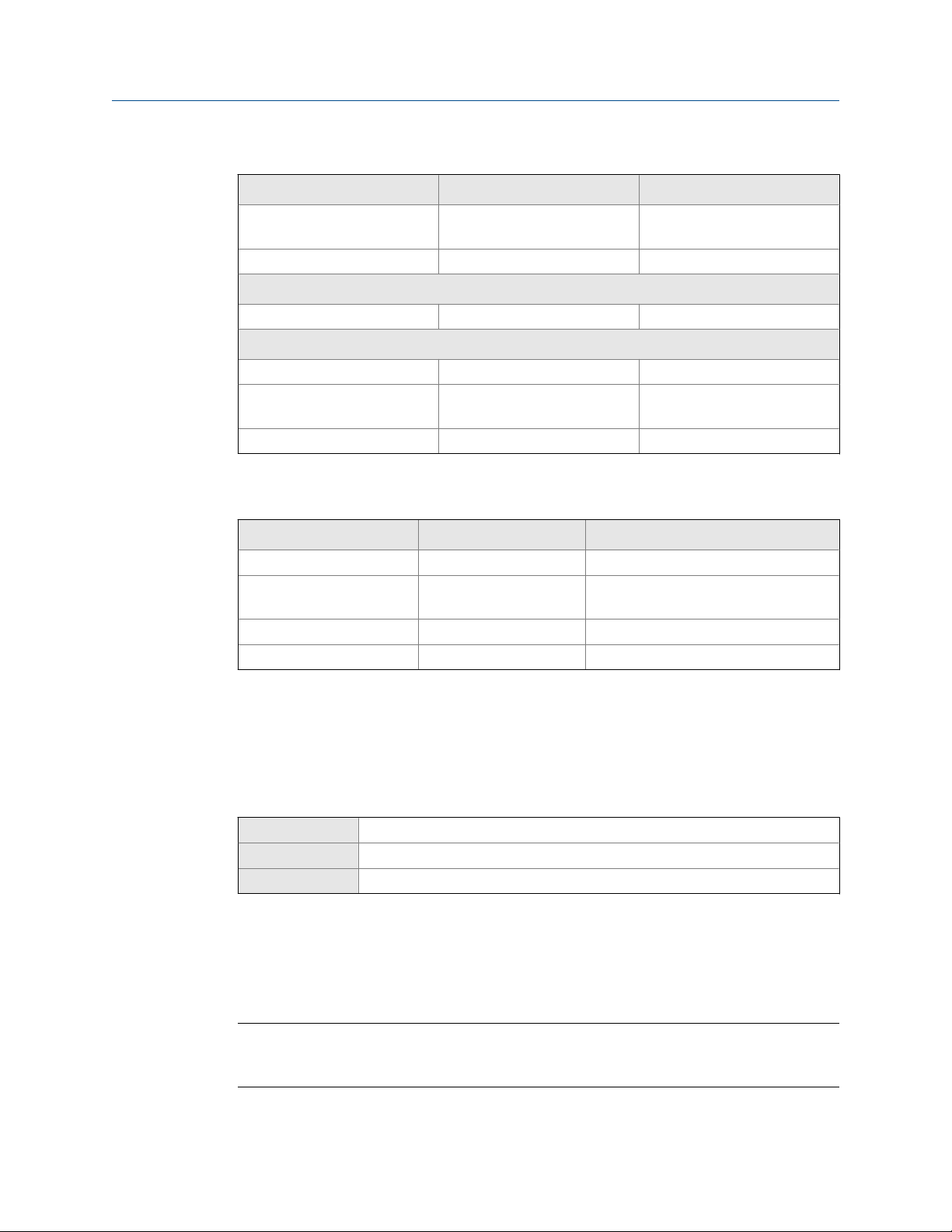
1. Power down the meter.
2. Using the strap wrench, loosen the grub screws and remove the transmitter end-
cap.
Transmitter with end-cap removedFigure 3-1:
Introduction to configuration and commissioning
A. Transmitter end‐cap
3. Using the hex key, remove the safety spacer.
Configuration and Use Manual 17
Page 26
A
B
A
B
Introduction to configuration and commissioning
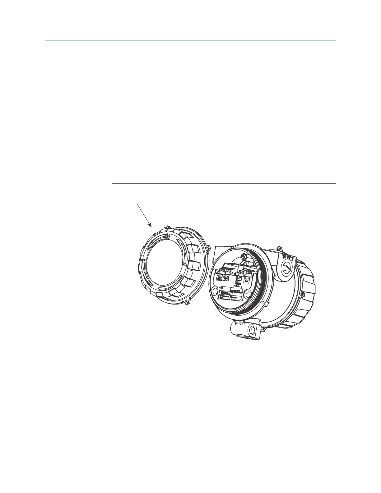
Transmitter with end-cap and safety spacer removedFigure 3-2:
A. Transmitter end‐cap
B. Safety spacer
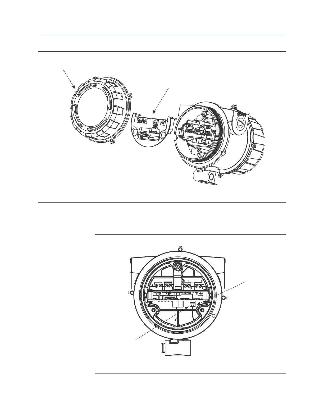
4. Move the HART security switch to the OFF position (up).
The HART security switch is the switch on the left.
HART security switchFigure 3-3:
A. HART security switch
B. Unused
18 Micro Motion® Compact Density Meters (CDM)
Page 27

5. Replace the safety spacer and end-cap.
6. Power up the meter.
3.4 Set the HART lock
If you plan to use a HART connection to configure the device, you can lock out all other
HART masters. If you do this, other HART masters will be able to read data from the device
but will not be able to write data to the device.
Restrictions
• This feature is available only when you are using the Field Communicator or AMS.
• This feature is available only with a HART 7 host.
Procedure
1. Choose Configure > Manual Setup > Security > Lock/Unlock Device.
2. If you are locking the meter, set Lock Option as desired.
Introduction to configuration and commissioning
Option Description
Permanent Only the current HART master can make changes to the device. The device will
remain locked until manually unlocked by a HART master. The HART master can
also change Lock Option to Temporary.
Temporary Only the current HART master can make changes to the device. The device will
remain locked until manually unlocked by a HART master, or a power-cycle or
device reset is performed. The HART master can also change Lock Option to Perma-
nent.
Lock All No HART masters are allowed to make changes to the configuration. Before
changing Lock Option to Permanent or Temporary, the device must be unlocked. Any
HART master can be used to unlock the device.
Postrequisites
To avoid future confusion or difficulties, ensure that the device is unlocked after you have
completed your tasks.
3.5 Restore the factory configuration
Display Not available
ProLink III Device Tools > Configuration Transfer > Restore Factory Configuration
Field Communicator Service Tools > Maintenance > Reset/Restore > Restore Factory Configuration
Configuration and Use Manual 19
Page 28

Introduction to configuration and commissioning
Overview
Restoring the factory configuration returns the transmitter to a known operational
configuration. This may be useful if you experience problems during configuration.
Tip
Restoring the factory configuration is not a common action. You may want to contact Micro Motion
to see if there is a preferred method to resolve any issues.
20 Micro Motion® Compact Density Meters (CDM)
Page 29

Configure process measurement
4 Configure process measurement
Topics covered in this chapter:
• Verify the calibration factors
• Configure line density measurement
• Configure temperature measurement
• Configure the pressure input
• Set up the API referral application
• Set up concentration measurement
• Set up flow monitoring
4.1 Verify the calibration factors
Display Not available
ProLink III Device Tools > Calibration Data
Field Communicator Configure > Manual Setup > Calibration Factors
Overview
The calibration factors are used to adjust measurement for the unique traits of the sensor.
Your device was calibrated at the factory. However, you should verify that the calibration
factors that are configured in your device match the factory values.
Prerequisites
You will need the factory values for the calibration factors. These are provided in two
locations:
• The calibration certificate shipped with your meter
• The label inside the transmitter's end-cap
Important
If the transmitter is not the original component, do not use the values from the transmitter label.
Procedure
1. View the calibration factors that are stored in the device.
2. Compare them to the factory values.
• If the values match, no action is required.
• If the values do not match, contact Micro Motion customer service.
Configuration and Use Manual 21
Page 30

Configure process measurement
Related information
Sample calibration certificates
4.1.1 Calibration factors
The original calibration factors are obtained from factory calibration, and are unique to
each device. They are used to adjust measurements for the specific physical properties of
the device.
Contents of the calibration certificate
The calibration certificate contains several sets of factors:
Density calibration
coefficients
Temperature
compensation coefficients
Pressure compensation
coefficients
Flow compensation
coefficient
The calibration certificate also provides the results of the Known Density Verification
procedure that was performed at the factory.
For each calibration performed at the factory, the calibration certificate contains the data
used to calculate the calibration coefficients.
CDM format and legacy format (A factors and K factors)
The calibration factors are provided on three calibration certificates:
• The first certificate provides the calibration factors in the CDM format, An, in SI units.
These are obtained from factory calibration of your device.
• The second certificate provides the calibration factors in the legacy format, Kn, in SI
units. These factors represent the current calibration factors converted to the
format used by the 7835 and 7845 meters.
• The third certificate provides the calibration factors in the legacy format, Kn, in
imperial units. These factors represent the current calibration factors converted to
the format used by the 7835 and 7845 meters, and then converted to imperial units.
Define the relationship between density and the response
of your sensor
Adjust density measurement for the effect of temperature
on sensor response
Adjust density measurement for the effect of pressure on
sensor response
Adjusts density measurement for the effect of flow on
sensor response
If you have existing programs that use the K factors, update your programs with the new K
values in the appropriate units. In all other situations, use the A-format calibration factors.
Related information
Sample calibration certificates
22 Micro Motion® Compact Density Meters (CDM)
Page 31

Configure process measurement
4.2 Configure line density measurement
The density measurement parameters control how density is measured and reported.
• Configure Density Measurement Unit (Section 4.2.1)
• Configure Density Damping (Section 4.2.2)
• Configure Density Cutoff (Section 4.2.3)
• Configure two‐phase flow parameters (Section 4.2.4)
4.2.1 Configure Density Measurement Unit
Display OFF-LINE MAINT > OFF-LINE CONFG > UNITS > DENS
ProLink III Device Tools > Configuration > Process Measurement > Line Density > Density Unit
Field Communicator Configure > Manual Setup > Measurements > Density > Density Unit
Overview
Density Measurement Unit controls the measurement units that will be used in density
calculations and reporting.
Restriction
If the API referral application is enabled, you cannot change the density measurement unit here. The
density measurement unit is controlled by the API table selection.
Procedure
Set Density Measurement Unit to the option you want to use.
The default setting for Density Measurement Unit is g/cm3 (grams per cubic centimeter).
Related information
Set up the API referral application
Options for Density Measurement Unit
The transmitter provides a standard set of measurement units for Density Measurement Unit.
Different communications tools may use different labels.
Options for Density Measurement UnitTable 4-1:
Label
Unit description
Specific gravity SGU SGU SGU
Grams per cubic centimeter G/CM3 g/cm3 g/Cucm
Grams per liter G/L g/l g/L
Configuration and Use Manual 23
Display (standard) ProLink III Field Communicator
Page 32

Configure process measurement
Options for Density Measurement Unit (continued)Table 4-1:
Label
Unit description
Grams per milliliter G/mL g/ml g/mL
Kilograms per liter KG/L kg/l kg/L
Kilograms per cubic meter KG/M3 kg/m3 kg/Cum
Pounds per U.S. gallon LB/GAL lbs/Usgal lb/gal
Pounds per cubic foot LB/CUF lbs/ft3 lb/Cuft
Pounds per cubic inch LB/CUI lbs/in3 lb/CuIn
Short ton per cubic yard ST/CUY sT/yd3 STon/Cuyd
Degrees API D API degAPI degAPI
Special unit SPECL special Spcl
Display (standard) ProLink III Field Communicator
Define a special measurement unit for density
Display Not available
ProLink III Device Tools > Configuration > Process Measurement > Line Density > Special Units
Field Communicator Configure > Manual Setup > Measurements > Special Units
Overview
A special measurement unit is a user-defined unit of measure that allows you to report
process data in a unit that is not available in the transmitter. A special measurement unit is
calculated from an existing measurement unit using a conversion factor.
Procedure
1. Specify Density Special Unit Base.
Density Special Unit Base is the existing density unit that the special unit will be based
on.
2. Calculate Density Special Unit Conversion Factor as follows:
a. x base units = y special units
b. Density Special Unit Conversion Factor = x÷y
3. Enter Density Special Unit Conversion Factor.
The original density value is divided by this conversion factor.
4. Set User-Defined Label to the name you want to use for the density unit.
The special measurement unit is stored in the transmitter. You can configure the
transmitter to use the special measurement unit at any time.
24 Micro Motion® Compact Density Meters (CDM)
Page 33

Example: Defining a special measurement unit for density
You want to measure density in ounces per cubic inch.
1. Set Density Special Unit Base to g/cm3.
2. Calculate Density Special Unit Conversion Factor:
a. 1 g/cm3 = 0.578 oz/in3
b. 1÷0.578 = 1.73
3. Set Density Special Unit Conversion Factor to 1.73.
4. Set User-Defined Label to oz/in3.
4.2.2 Configure Density Damping
Display Not available
ProLink III Device Tools > Configuration > Process Measurement > Line Density > Density Damping
Field Communicator Configure > Manual Setup > Measurements > Density > Density Damping
Configure process measurement
Overview
Density Damping controls the amount of damping that will be applied to the line density
value.
Damping is used to smooth out small, rapid fluctuations in process measurement. Damping
Value specifies the time period (in seconds) over which the transmitter will spread changes
in the process variable. At the end of the interval, the internal value will reflect 63% of the
change in the actual measured value.
Tip
Density damping affects all process variables that are calculated from line density.
Procedure
Set Density Damping to the value you want to use.
The default value is 1.6 seconds. The range is 0 to 60 seconds.
Interaction between Density Damping and Added Damping
When the mA output is configured to report density, both Density Damping and Added
Damping are applied to the reported density value.
Density Damping controls the rate of change in the value of the process variable in
transmitter memory. Added Damping controls the rate of change reported via the mA
output.
Configuration and Use Manual 25
Page 34

Configure process measurement
If mA Output Process Variable is set to Density, and both Density Damping and Added Damping are
set to non-zero values, density damping is applied first, and the added damping
calculation is applied to the result of the first calculation. This value is reported over the
mA output.
Related information
Interaction between mA Output Damping and process variable damping
4.2.3 Configure Density Cutoff
Display Not available
ProLink III Device Tools > Configuration > Process Measurement > Line Density > Density Cutoff Low
Field Communicator Configure > Manual Setup > Measurements > Density > Density Cutoff
Overview
Density Cutoff Low specifies the lowest density value that will be reported as measured. All
density values below this cutoff will be reported as 0.
Procedure
Set Density Cutoff Low to the value you want to use.
The default value is 0.2 g/cm³. The range is 0.0 g/cm³ to 0.5 g/cm³.
4.2.4 Configure two-phase flow parameters
Display Not available
ProLink III Device Tools > Configuration > Process Measurement > Line Density
Field Communicator Configure > Manual Setup > Measurements > Density
Overview
The two-phase flow parameters control how the transmitter detects and reports twophase flow (gas in a liquid process or liquid in a gas process).
Note
Two-phase flow is sometimes referred to as slug flow.
Procedure
1. Set Two-Phase Flow Low Limit to the lowest density value that is considered normal in
your process.
Values below this will cause the transmitter to post Alert A105 (Two-Phase Flow).
26 Micro Motion® Compact Density Meters (CDM)
Page 35

Configure process measurement
Tip
Gas entrainment can cause your process density to drop temporarily. To reduce the
occurrence of two-phase flow alerts that are not significant to your process, set Two-Phase Flow
Low Limit slightly below your expected lowest process density.
You must enter Two-Phase Flow Low Limit in g/cm³, even if you configured another unit
for density measurement.
The default value for Two-Phase Flow Low Limit is 0.0 g/cm³. The range is 0.0 to
3.0 g/cm³.
2. Set Two-Phase Flow High Limit to the highest density value that is considered normal in
your process.
Values above this will cause the transmitter to post Alert A105 (Two-Phase Flow).
Tip
To reduce the occurrence of two-phase flow alerts that are not significant to your process, set
Two-Phase Flow High Limit slightly above your expected highest process density.
You must enter Two-Phase Flow High Limit in g/cm³, even if you configured another
unit for density measurement.
The default value for Two-Phase Flow High Limit is 3.0 g/cm³. The range is 0.0 to
3.0 g/cm³.
3. Set Two-Phase Flow Timeout to the number of seconds that the transmitter will wait for
a two-phase flow condition to clear before posting the alert.
The default value for Two-Phase Flow Timeout is 0.0 seconds, meaning that the alert
will be posted immediately. The range is 0.0 to 60.0 seconds.
Detecting and reporting two-phase flow
Two-phase flow (gas in a liquid process or liquid in a gas process) can cause a variety of
process control issues. By configuring the two-phase flow parameters appropriately for
your application, you can detect process conditions that require correction.
Tip
To decrease the occurrence of two-phase flow alerts, lower Two-Phase Flow Low Limit or raise Two-Phase
Flow High Limit.
A two-phase flow condition occurs whenever the measured density goes below Two-Phase
Flow Low Limit or above Two-Phase Flow High Limit. If this occurs:
• A two-phase flow alert is posted to the active alert log.
• Line density is held at its last pre‐alert value for the number of seconds configured in
Two-Phase Flow Timeout.
If the two-phase flow condition clears before Two-Phase Flow Timeout expires:
Configuration and Use Manual 27
Page 36

Configure process measurement
• Line density reverts to actual process density.
• The two-phase flow alert is deactivated, but remains in the active alert log until it is
acknowledged.
If the two-phase flow condition does not clear before Two-Phase Flow Timeout expires, line
density reverts to actual process density, but the two-phase flow alert remains active.
If Two-Phase Flow Timeout is set to 0.0 seconds, two-phase flow will cause a two-phase flow
alert but will have no effect on how the meter measures or reports line density.
4.3 Configure temperature measurement
The temperature measurement parameters control how temperature data from the
sensor is reported.
• Configure Temperature Measurement Unit (Section 4.3.1)
• Configure Temperature Damping (Section 4.3.2)
• Configure Temperature Input (Section 4.3.3)
4.3.1 Configure Temperature Measurement Unit
Display OFF-LINE MAINT > OFF-LINE CONFG > UNITS > TEMP
ProLink III Device Tools > Configuration > Process Measurement > Line Temperature > Temperature Unit
Field Communicator Configure > Manual Setup > Measurements > Temperature > Temperature Unit
Overview
Temperature Measurement Unit specifies the unit that will be used for temperature
measurement.
Restriction
If the API referral application is enabled, the API table selection automatically sets the temperature
measurement unit. Configure the API referral application first, then change the temperature
measurement unit if desired.
Procedure
Set Temperature Measurement Unit to the option you want to use.
The default setting is Degrees Celsius.
Related information
Set up the API referral application
28 Micro Motion® Compact Density Meters (CDM)
Page 37

Options for Temperature Measurement Unit
The transmitter provides a standard set of units for Temperature Measurement Unit. Different
communications tools may use different labels for the units.
Options for Temperature Measurement UnitTable 4-2:
Unit description
Degrees Celsius °C °C degC
Degrees Fahrenheit °F °F degF
Degrees Rankine °R °R degR
Kelvin °K °K Kelvin
Display ProLink III
4.3.2 Configure Temperature Damping
Configure process measurement
Label
Field Communicator
Display Not available
ProLink III Device Tools > Configuration > Process Measurement > Line Temperature > Temperature Damping
Field Communicator Configure > Manual Setup > Measurements > Temperature > Temp Damping
Overview
Temperature Damping controls the amount of damping that will be applied to the line
temperature value, when the on-board temperature data is used (RTD).
Damping is used to smooth out small, rapid fluctuations in process measurement. Damping
Value specifies the time period (in seconds) over which the transmitter will spread changes
in the process variable. At the end of the interval, the internal value will reflect 63% of the
change in the actual measured value.
Tip
Temperature Damping affects all process variables, compensations, and corrections that use
temperature data from the sensor.
Procedure
Enter the value you want to use for Temperature Damping.
• Default: 4.8 seconds
Tips
• A high damping value makes the process variable appear smoother because the reported value
changes slowly.
Configuration and Use Manual 29
Page 38

Configure process measurement
• A low damping value makes the process variable appear more erratic because the reported value
changes more quickly.
• Whenever the damping value is non-zero, the reported measurement will lag the actual
measurement because the reported value is being averaged over time.
• In general, lower damping values are preferable because there is less chance of data loss, and less
lag time between the actual measurement and the reported value.
The value you enter is automatically rounded down to the nearest valid value.
4.3.3 Configure Temperature Input
Temperature data from the on-board temperature sensor (RTD) is always available.
Optionally, you can set up an external temperature device and use external temperature
data.
Tip
Use an external device only if it is more accurate than the internal RTD.
Important
Line temperature data is used in several different measurements and calculations. It is possible to
use the internal RTD temperature in some areas and an external temperature in others. The
transmitter stores the internal RTD temperature and the external temperature separately. However,
the transmitter stores only one alternate temperature value, which may be either an external
temperature or the configured fixed value. Accordingly, if you set up polling for temperature in one
area, and digital communications in another, and configure a fixed temperature value in a third, the
fixed value will be overwritten by polling and digital communications, and polling and digital
communications will overwrite each other.
Prerequisites
If you plan to poll an external device, the primary mA output (Channel A) must be wired to
support HART communications.
• Configure Temperature Input using ProLink III
• Configure Temperature Input using the Field Communicator
Configure Temperature Input using ProLink III
ProLink III Device Tools > Configuration > Process Measurement > Line Temperature > Line Temperature Source
Procedure
Choose the method to be used to supply temperature data, and perform the required
setup.
30 Micro Motion® Compact Density Meters (CDM)
Page 39

Option Description Setup
Internal RTD temperature data
Polling The meter polls an external de-
Digital communications
Temperature data from the onboard temperature sensor
(RTD) is used.
vice for temperature data. This
data will be available in addition to the internal RTD temperature data.
A host writes temperature data
to the meter at appropriate intervals. This data will be available in addition to the internal
RTD temperature data.
a. Set Line Temperature Source to Internal RTD.
b. Click Apply.
a. Set Line Temperature Source to Poll for External Value.
b. Set Polling Slot to an available slot.
c. Set Polling Control to Poll as Primary or Poll as Secondary.
Option Description
Poll as Primary No other HART masters will be on the
Poll as Secondary Other HART masters will be on the net-
d. Set External Device Tag to the HART tag of the temperature
device.
e. Click Apply.
a. Set Line Temperature Source to Fixed Value or Digital Communica-
tions.
b. Click Apply.
c. Perform the necessary host programming and communica-
tions setup to write temperature data to the meter at appro-
priate intervals.
Configure process measurement
network. The Field Communicator is not
a HART master.
work. The Field Communicator is not a
HART master.
Postrequisites
If you are using external temperature data, verify the external temperature value displayed
in the Inputs group on the ProLink III main window.
Need help? If the value is not correct:
• For polling:
- Verify the wiring between the meter and the external device.
- Verify the HART tag of the external device.
• For digital communications:
- Verify that the host has access to the required data.
- Verify that the host is writing to the correct register in memory, using the correct data
type.
Configure Temperature Input using the Field Communicator
Choose the method to be used to supply temperature data, and perform the required
setup.
Configuration and Use Manual 31
Page 40

Configure process measurement
Method Description Setup
Internal RTD temperature data
Polling The meter polls an external de-
Temperature data from the onboard temperature sensor
(RTD) is used.
vice for temperature data. This
data will be available in addition to the internal RTD temperature data.
a. Choose Configure > Manual Setup > Measurements > External Inputs
b. Set External Temperature to Disable.
a. Choose Configure > Manual Setup > Measurements > External Inputs
b. Set External Temperature to Enable.
c. Choose Configure > Manual Setup > Inputs/Outputs > External Device
d. Choose an unused polling slot.
e. Set Poll Control to Poll as Primary or Poll as Secondary.
Option Description
Poll as Primary No other HART masters will be on the
Poll as Secondary Other HART masters will be on the net-
> Temperature.
> Temperature.
Polling.
network. The Field Communicator is not
a HART master.
work. The Field Communicator is not a
HART master.
Digital communications
f. Set External Device Tag to the HART tag of the external tem-
perature device.
g. Set Polled Variable to Temperature.
A host writes temperature data
to the meter at appropriate intervals. This data will be available in addition to the internal
RTD temperature data.
a. Choose Configure > Manual Setup > Measurements > External Inputs
> Temperature.
b. Set External Temperature to Enable.
c. Perform the necessary host programming and communica-
tions setup to write temperature data to the meter at appro-
priate intervals.
Postrequisites
Choose Service Tools > Variables > External Variables and verify the value for External
Temperature.
Need help? If the value is not correct:
• Ensure that the external device and the meter are using the same measurement unit.
• For polling:
- Verify the wiring between the meter and the external device.
- Verify the HART tag of the external device.
• For digital communications:
- Verify that the host has access to the required data.
- Verify that the host is writing to the correct register in memory, using the correct data
type.
• If necessary, apply an offset.
32 Micro Motion® Compact Density Meters (CDM)
Page 41

4.4 Configure the pressure input
Pressure data is required to calculate base density from line density.
• The meter does not measure pressure, so you must provide an external pressure
input.
• You must use absolute pressure.
• Pressure data is required for several different measurements.
• There are several different methods to obtain pressure data.
Tip
A fixed pressure value is not recommended as it can produce inaccurate process data.
Prerequisites
If you plan to poll an external device, the primary mA output (Channel A) must be wired to
support HART communications.
• Configure the pressure input using ProLink III (Section 4.4.1)
• Configure the pressure input using the Field Communicator (Section 4.4.2)
Configure process measurement
4.4.1 Configure the pressure input using ProLink III
1. Choose Device Tools > Configuration > Process Measurement > Line Pressure.
2. Set Pressure Type to match the pressure measurement from the external pressure
device.
Option Description
Absolute The external pressure device reports absolute pressure.
Gauge The external pressure device reports gauge pressure.
Restriction
If Line Pressure Source is set to Fixed, you cannot configure Pressure Type. You must enter the
pressure value in the required form. To set Pressure Type, you may need to change the setting
of Line Pressure Source.
The meter requires gauge pressure. If you select Absolute, the device will convert the
input pressure value to the equivalent gauge pressure.
3. Set Pressure Unit to the unit used by the external pressure device.
Restriction
If the API referral application is enabled, the API table selection automatically sets the
pressure measurement unit. Configure the API referral application first, then change the
pressure measurement unit if necessary.
Configuration and Use Manual 33
Page 42

Configure process measurement
4. Choose the method used to supply pressure data and perform the required setup.
Option Description Setup
Polling The meter polls an external de-
vice for pressure data.
Digital communications
A host writes pressure data to
the meter at appropriate intervals.
a. Set Pressure Source to Poll for External Value.
b. Set Polling Slot to an available slot.
c. Set Polling Control to Poll as Primary or Poll as Secondary.
Option Description
Poll as Primary No other HART masters will be on the
Poll as Secondary Other HART masters will be on the net-
d. Set External Device Tag to the HART tag of the temperature
a. Set Pressure Source to Fixed Value or Digital Communications.
b. Perform the necessary host programming and communica-
network. The Field Communicator is not
a HART master.
work. The Field Communicator is not a
HART master.
device.
tions setup to write pressure data to the meter at appropriate intervals.
Postrequisites
The current pressure value is displayed in the External Pressure field. Verify that the value is
correct.
Need help? If the value is not correct:
• Ensure that the external device and the meter are using the same measurement unit.
• For polling:
- Verify the wiring between the meter and the external device.
- Verify the HART tag of the external device.
• For digital communications:
- Verify that the host has access to the required data.
- Verify that the host is writing to the correct register in memory, using the correct data
type.
• If necessary, apply an offset.
Note
Do not use the offset in conjunction with the fixed pressure value. Enter the adjusted value.
Related information
Set up the API referral application
34 Micro Motion® Compact Density Meters (CDM)
Page 43

4.4.2 Configure the pressure input using the Field Communicator
1. Choose Configure > Manual Setup > Measurements > External Inputs > Pressure.
2. Set Pressure Input to Enable.
3. Set Pressure Type to match the pressure measurement from the external pressure
device.
Option Description
Absolute The external pressure device reports absolute pressure.
Gauge The external pressure device reports gauge pressure.
Restriction
If Line Pressure Source is set to Fixed, you cannot configure Pressure Type. You must enter the
pressure value in the required form. To set Pressure Type, you may need to change the setting
of Line Pressure Source.
Configure process measurement
The meter requires gauge pressure. If you select Absolute, the device will convert the
input pressure value to the equivalent gauge pressure.
4. Set Pressure Unit to the unit used by the external pressure device.
Restriction
If the API referral application is enabled, the API table selection automatically sets the
pressure measurement unit. Configure the API referral application first, then change the
pressure measurement unit if necessary.
5. Set up the pressure input.
a. Choose Configure > Manual Setup > Inputs/Outputs > External Device Polling.
b. Choose an unused polling slot.
c. Set Polling Control to Poll as Primary or Poll as Secondary.
Option Description
Poll as Primary No other HART masters will be on the network. The
Field Communicator is not a HART master.
Poll as Secondary Other HART masters will be on the network. The
Field Communicator is not a HART master.
d. Set External Device Tag to the HART tag of the external pressure device.
e. Set Polled Variable to Pressure.
Postrequisites
Choose Service Tools > Variables > External Variables and verify the value for External Pressure.
Configuration and Use Manual 35
Page 44

Configure process measurement
Need help? If the value is not correct:
• Ensure that the external device and the meter are using the same measurement unit.
• For polling:
- Verify the wiring between the meter and the external device.
- Verify the HART tag of the external device.
• For digital communications:
- Verify that the host has access to the required data.
- Verify that the host is writing to the correct register in memory, using the correct data
type.
• If necessary, apply an offset.
Related information
Set up the API referral application
4.4.3 Options for Pressure Measurement Unit
The transmitter provides a standard set of measurement units for Pressure Measurement Unit.
Different communications tools may use different labels for the units. In most
applications, Pressure Measurement Unit should be set to match the pressure measurement
unit used by the remote device.
Options for Pressure Measurement UnitTable 4-3:
Label
Unit description
Feet water @ 68 °F FTH2O Ft Water @ 68°F ftH2O
Inches water @ 4 °C INW4C In Water @ 4°C inH2O @4DegC
Inches water @ 60 °F INW60 In Water @ 60°F inH2O @60DegF
Inches water @ 68 °F INH2O In Water @ 68°F inH2O
Millimeters water @ 4 °C mmW4C mm Water @ 4°C mmH2O @4DegC
Millimeters water @ 68 °F mmH2O mm Water @ 68°F mmH2O
Millimeters mercury @ 0 °C mmHG mm Mercury @ 0°C mmHg
Inches mercury @ 0 °C INHG In Mercury @ 0°C inHG
Pounds per square inch PSI PSI psi
Bar BAR bar bar
Millibar mBAR millibar mbar
Grams per square centimeter G/SCM g/cm2 g/Sqcm
Kilograms per square centimeter KG/SCM kg/cm2 kg/Sqcm
Pascals PA pascals Pa
Kilopascals KPA Kilopascals kPa
Megapascals MPA Megapascals MPa
Display ProLink III Field Communicator
36 Micro Motion® Compact Density Meters (CDM)
Page 45

Configure process measurement
Options for Pressure Measurement Unit (continued)Table 4-3:
Label
Unit description
Torr @ 0 °C TORR Torr @ 0°C torr
Atmospheres ATM atms atms
Display ProLink III Field Communicator
4.5 Set up the API referral application
The API referral application corrects line density to reference temperature and reference
pressure according to American Petroleum Institute (API) standards. The resulting process
variable is referred density.
• Set up the API referral application using ProLink III (Section 4.5.1)
• Set up the API referral application using the Field Communicator (Section 4.5.2)
4.5.1 Set up the API referral application using ProLink III
This section guides you through the tasks required to set up and implement the API
referral application.
1. Enable the API referral application using ProLink III
2. Configure API referral using ProLink III
3. Set up temperature and pressure data for API referral using ProLink III
Enable the API referral application using ProLink III
The API referral application must be enabled before you can perform any setup. If the API
referral application was enabled at the factory, you do not need to enable it now.
1. Choose Device Tools > Configuration > Transmitter Options.
2. If the concentration measurement application is enabled, disable it and click Apply.
The concentration measurement application and the API referral application cannot
be enabled simultaneously.
3. Enable API Referral and click Apply.
Configure API referral using ProLink III
The API referral parameters specify the API table, measurement units, and reference values
to be used in referred density calculations.
Prerequisites
You will need API documentation for the API table that you select.
Configuration and Use Manual 37
Page 46

Configure process measurement
Depending on your API table, you may need to know the thermal expansion coefficient
(TEC) for your process fluid.
You must know the reference temperature and reference pressure that you want to use.
Procedure
1. Choose Device Tools > Configuration > Process Measurement > API Referral.
2. Specify the API table to use.
Each API table is associated with a specific set of equations.
a. Set Process Fluid to the API table group that your process fluid belongs to.
API table group Process fluids
A tables Generalized crude and JP4
B tables Generalized products: Gasoline, jet fuel, aviation fuel, kerosene,
heating oils, fuel oils, diesel, gas oil
C tables Liquids with a constant base density or known thermal expansion
coefficient (TEC). You will be required to enter the TEC for your
process fluid.
D tables Lubricating oils
E tables NGL (Natural Gas Liquids) and LPG (Liquid Petroleum Gas)
Restriction
The API referral application is not appropriate for the following process fluids: propane
and propane mixes, butane and butane mixes, butadiene and butadiene mixes,
isopentane, LNG, ethylene, propylene, cyclohexane, aeromatics, asphalts, and road tars.
b. Set Referred Density Measurement Unit to the measurement units that you want to
use for referred density.
c. Click Apply.
These parameters uniquely identify the API table. The selected API table is displayed,
and the meter automatically changes the density unit, temperature unit, pressure
unit, reference temperature, and reference pressure to match the API table.
Restriction
Not all combinations are supported by the API referral application. See the list of API tables in
this manual.
3. Refer to the API documentation and confirm your table selection.
a. Verify that your process fluid falls within range for line density, line temperature,
and line pressure.
38 Micro Motion® Compact Density Meters (CDM)
Page 47

Configure process measurement
If your process fluid goes outside any of these limits, the meter will post a status
alert and will report line density instead of referred density until the process fluid
goes back within range.
b. Verify that the referred density range of the selected table is adequate for your
application.
4. If you chose a C table, enter Thermal Expansion Coefficient (TEC) for your process fluid.
5. Set Reference Temperature to the temperature to which density will be corrected in
referred density calculations. If you choose Other, select the temperature
measurement unit and enter the reference temperature.
6. Set Reference Pressure to the pressure to which density will be corrected in referred
density calculations.
API tables supported by the API referral application
The API tables listed here are supported by the API referral application.
API tables, process fluids, measurement units, and default reference valuesTable 4-4:
Process fluid API table Referred density (API)
Generalized crude and JP4 5A Unit: °API
Range: 0 to 100 °API
23A Unit: SGU
Range: 0.6110 to 1.0760
SGU
53A Unit: kg/m
Range: 610 to 1075 kg/m³
Generalized products (gasoline, jet fuel, aviation fuel,
kerosene, heating oils, fuel
oils, diesel, gas oil)
Liquids with a constant density base or known thermal
expansion coefficient
Lubricating oils 5D Unit: °API
5B Unit: °API
Range: 0 to 85 °API
23B Unit: SGU
Range: 0.6535 to 1.0760
SGU
53B Unit: kg/m
Range: 653 to 1075 kg/m³
6C Unit: °API 60 °F 0 psi (g)
24C Unit: SGU 60 °F 0 psi (g)
54C Unit: kg/m³ 15 °C 0 kPa (g)
Range: −10 to +40 °API
23D Unit: SGU
Range: 0.8520 to 1.1640
SGU
53D Unit: kg/m³
Range: 825 to 1164 kg/m³
3
3
Default reference
temperature
60 °F 0 psi (g)
60 °F 0 psi (g)
15 °C 0 kPa (g)
60 °F 0 psi (g)
60 °F 0 psi (g)
15 °C 0 kPa (g)
60 °F 0 psi (g)
60 °F 0 psi (g)
15 °C 0 kPa (g)
Default reference
pressure
Configuration and Use Manual 39
Page 48

Configure process measurement
API tables, process fluids, measurement units, and default reference values (continued)Table 4-4:
Default reference
Process fluid API table Referred density (API)
NGL (natural gas liquids) 23E Unit: SGU 60 °F 0 psi (g)
LPG (liquid petroleum gas) 24E Unit: SGU 60 °F 0 psi (g)
Restriction
These tables are not appropriate for the following process fluids: propane and propane mixes,
butane and butane mixes, butadiene and butadiene mixes, isopentane, LNG, ethylene, propylene,
cyclohexane, aeromatics, asphalts, and road tars.
temperature
Default reference
pressure
Set up temperature and pressure data for API referral using ProLink III
The API referral application uses temperature and, optionally, pressure data in its
calculations. You must decide how to provide this data, then perform the required
configuration and setup.
Tip
Fixed values for temperature or pressure are not recommended. Using a fixed temperature or
pressure value may produce inaccurate process data.
Important
Line temperature data is used in several different measurements and calculations. It is possible to
use the internal RTD temperature in some areas and an external temperature in others. The
transmitter stores the internal RTD temperature and the external temperature separately. However,
the transmitter stores only one alternate temperature value, which may be either an external
temperature or the configured fixed value. Accordingly, if you set up polling for temperature in one
area, and digital communications in another, and configure a fixed temperature value in a third, the
fixed value will be overwritten by polling and digital communications, and polling and digital
communications will overwrite each other.
Important
Line pressure data is used in several different measurements and calculations. The transmitter stores
only one pressure value, which may be either the external pressure or the configured fixed value.
Accordingly, if you choose a fixed pressure for some uses, and an external pressure for others, the
external pressure will overwrite the fixed value.
Prerequisites
• If you plan to poll an external device, the primary mA output (Channel A) must be
wired to support HART communications.
• The pressure measurement must be gauge pressure, not atmospheric pressure. If
your pressure input is absolute, you can set the pressure type to absolute and it will
be converted to gauge for the API calculations.
• The pressure device must use the pressure unit that is configured in the transmitter.
40 Micro Motion® Compact Density Meters (CDM)
Page 49

• If you are using an external temperature device, it must use the temperature unit
that is configured in the transmitter.
Procedure
1. Choose Device Tools > Configuration > Process Measurement > API Referral.
2. Choose the method to be used to supply temperature data, and perform the
required setup.
Option Description Setup
Internal RTD temperature data
Polling The meter polls an external de-
Temperature data from the onboard temperature sensor
(RTD) is used.
vice for temperature data. This
data will be available in addition to the internal RTD temperature data.
a. Set Line Temperature Source to Internal RTD.
b. Click Apply.
a. Set Line Temperature Source to Poll for External Value.
b. Set Polling Slot to an available slot.
c. Set Polling Control to Poll as Primary or Poll as Secondary.
Option Description
Poll as Primary No other HART masters will be on the
Poll as Secondary Other HART masters will be on the net-
Configure process measurement
network. The Field Communicator is not
a HART master.
work. The Field Communicator is not a
HART master.
Digital communications
d. Set External Device Tag to the HART tag of the temperature
device.
e. Click Apply.
A host writes temperature data
to the meter at appropriate intervals. This data will be available in addition to the internal
RTD temperature data.
a. Set Line Temperature Source to Fixed Value or Digital Communica-
tions.
b. Click Apply.
c. Perform the necessary host programming and communica-
tions setup to write temperature data to the meter at appro-
priate intervals.
3. Choose the method used to supply pressure data and perform the required setup.
Configuration and Use Manual 41
Page 50

Configure process measurement
Option Description Setup
Polling The meter polls an external de-
vice for pressure data.
Digital communications
A host writes pressure data to
the meter at appropriate intervals.
a. Set Pressure Source to Poll for External Value.
b. Set Polling Slot to an available slot.
c. Set Polling Control to Poll as Primary or Poll as Secondary.
Option Description
Poll as Primary No other HART masters will be on the
Poll as Secondary Other HART masters will be on the net-
d. Set External Device Tag to the HART tag of the temperature
a. Set Pressure Source to Fixed Value or Digital Communications.
b. Perform the necessary host programming and communica-
network. The Field Communicator is not
a HART master.
work. The Field Communicator is not a
HART master.
device.
tions setup to write pressure data to the meter at appropri-
ate intervals.
Postrequisites
If you are using external temperature data, verify the external temperature value displayed
in the Inputs group on the ProLink III main window.
The current pressure value is displayed in the External Pressure field. Verify that the value is
correct.
Need help? If the value is not correct:
• Ensure that the external device and the meter are using the same measurement unit.
• For polling:
- Verify the wiring between the meter and the external device.
- Verify the HART tag of the external device.
• For digital communications:
- Verify that the host has access to the required data.
- Verify that the host is writing to the correct register in memory, using the correct data
type.
• If necessary, apply an offset.
4.5.2 Set up the API referral application using the Field Communicator
This section guides you through the tasks required to set up and implement the API
referral application.
42 Micro Motion® Compact Density Meters (CDM)
Page 51

Configure process measurement
1. Enable the API referral application using the Field Communicator
2. Configure API referral using the Field Communicator
3. Set up temperature and pressure data for API referral using the Field Communicator
Enable the API referral application using the Field Communicator
The API referral application must be enabled before you can perform any setup. If the API
referral application was enabled at the factory, you do not need to enable it now.
1. Choose Overview > Device Information > Applications > Enable/Disable Applications.
2. If the concentration measurement application is enabled, disable it.
The concentration measurement application and the API referral application cannot
be enabled simultaneously.
3. Enable the API referral application.
Configure API referral using the Field Communicator
The API referral parameters specify the API table, measurement units, and reference values
to be used in referred density calculations.
Prerequisites
You will need API documentation for the API table that you select.
Depending on your API table, you may need to know the thermal expansion coefficient
(TEC) for your process fluid.
You must know the reference temperature and reference pressure that you want to use.
Procedure
1. Choose Configure > Manual Setup > Measurements > API Referral.
2. Choose API Referral Setup.
3. Specify the API table that you want to use for measurement.
Each API table is associated with a specific set of equations.
a. Set API Table Number to the number that matches the API table units that you
want to use for referred density.
Your choice also determines the measurement units to be used for temperature
and pressure, and the default values for reference temperature and reference
pressure.
Measurement
unit for referred
API Table Number
5 °API °F psi (g) 60 °F 0 psi (g)
density
Temperature
measurement
unit
Pressure measurement unit
Default reference temperature
Default reference pressure
Configuration and Use Manual 43
Page 52

Configure process measurement
API Table Number
(1)
6
Measurement
unit for referred
density
°API °F psi (g) 60 °F 0 psi (g)
Temperature
measurement
unit
Pressure measurement unit
Default reference temperature
Default reference pressure
23 SGU °F psi (g) 60 °F 0 psi (g)
(1)
24
SGU °F psi (g) 60 °F 0 psi (g)
53 kg/m³ °C kPa (g) 15 °C 0 kPa (g)
(1)
54
(1) Used only with API Table Letter = C.
kg/m³ °C kPa (g) 15 °C 0 kPa (g)
b. Set API Table Letter to the letter of the API table group that is appropriate for your
process fluid.
API Table Letter Process fluids
A Generalized crude and JP4
B Generalized products: Gasoline, jet fuel, aviation fuel, kerosene,
heating oils, fuel oils, diesel, gas oil
(1)
C
D Lubricating oils
E NGL (Natural Gas Liquids) and LPG (Liquid Petroleum Gas)
Liquids with a constant base density or known thermal expansion
coefficient (TEC). You will be required to enter the TEC for your
process fluid.
(1) Used only with API Table Number = 6, 24, or 54.
Restriction
The API referral application is not appropriate for the following process fluids: propane
and propane mixes, butane and butane mixes, butadiene and butadiene mixes,
isopentane, LNG, ethylene, propylene, cyclohexane, aeromatics, asphalts, and road tars.
API Table Number and API Table Letter uniquely identify the API table. The selected API
table is displayed, and the meter automatically changes the density unit,
temperature unit, pressure unit, reference temperature, and reference pressure to
match the API table.
Restriction
Not all combinations are supported by the API referral application. See the list of API tables in
this manual.
4. If you chose a C table, enter Thermal Expansion Coefficient (TEC) for your process fluid.
5. Refer to the API documentation and confirm your table selection.
a. Verify that your process fluid falls within range for line density, line temperature,
and line pressure.
44 Micro Motion® Compact Density Meters (CDM)
Page 53

Configure process measurement
If your process fluid goes outside any of these limits, the meter will post a status
alert and will report line density instead of referred density until the process fluid
goes back within range.
b. Verify that the referred density range of the selected table is adequate for your
application.
6. If required, set Ref Temperature to the temperature to which density will be corrected
in referred density calculations.
The default reference temperature is determined by the selected API table.
a. Choose Service Tools > Maintenance > Modbus Data > Write Modbus Data.
b. Write the desired reference temperature to Registers 319–320, in the
measurement unit required by the selected API table. Use 32-bit IEEE floatingpoint format.
7. If required, set Ref Pressure (Gauge) to the pressure to which density will be corrected
in referred density calculations.
The default reference pressure is determined by the selected API table. API referral
requires gauge pressure.
a. Choose Service Tools > Maintenance > Modbus Data > Write Modbus Data.
b. Write the desired reference pressure to Registers 4601–4602, in the
measurement unit required by the selected API table. Use 32-bit IEEE floatingpoint format.
API tables supported by the API referral application
The API tables listed here are supported by the API referral application.
API tables, process fluids, measurement units, and default reference valuesTable 4-5:
Process fluid API table Referred density (API)
Generalized crude and JP4 5A Unit: °API
Range: 0 to 100 °API
23A Unit: SGU
Range: 0.6110 to 1.0760
SGU
3
3
Generalized products (gasoline, jet fuel, aviation fuel,
kerosene, heating oils, fuel
oils, diesel, gas oil)
53A Unit: kg/m
Range: 610 to 1075 kg/m³
5B Unit: °API
Range: 0 to 85 °API
23B Unit: SGU
Range: 0.6535 to 1.0760
SGU
53B Unit: kg/m
Range: 653 to 1075 kg/m³
Default reference
temperature
60 °F 0 psi (g)
60 °F 0 psi (g)
15 °C 0 kPa (g)
60 °F 0 psi (g)
60 °F 0 psi (g)
15 °C 0 kPa (g)
Default reference
pressure
Configuration and Use Manual 45
Page 54

Configure process measurement
API tables, process fluids, measurement units, and default reference values (continued)Table 4-5:
Default reference
Process fluid API table Referred density (API)
Liquids with a constant density base or known thermal
expansion coefficient
Lubricating oils 5D Unit: °API
NGL (natural gas liquids) 23E Unit: SGU 60 °F 0 psi (g)
LPG (liquid petroleum gas) 24E Unit: SGU 60 °F 0 psi (g)
Restriction
These tables are not appropriate for the following process fluids: propane and propane mixes,
butane and butane mixes, butadiene and butadiene mixes, isopentane, LNG, ethylene, propylene,
cyclohexane, aeromatics, asphalts, and road tars.
6C Unit: °API 60 °F 0 psi (g)
24C Unit: SGU 60 °F 0 psi (g)
54C Unit: kg/m³ 15 °C 0 kPa (g)
Range: −10 to +40 °API
23D Unit: SGU
Range: 0.8520 to 1.1640
SGU
53D Unit: kg/m³
Range: 825 to 1164 kg/m³
temperature
60 °F 0 psi (g)
60 °F 0 psi (g)
15 °C 0 kPa (g)
Default reference
pressure
Set up temperature and pressure data for API referral using the Field Communicator
The API referral application uses temperature and, optionally, pressure data in its
calculations. You must decide how to provide this data, then perform the required
configuration and setup.
Tip
Fixed values for temperature or pressure are not recommended. Using a fixed temperature or
pressure value may produce inaccurate process data.
Important
Line temperature data is used in several different measurements and calculations. It is possible to
use the internal RTD temperature in some areas and an external temperature in others. The
transmitter stores the internal RTD temperature and the external temperature separately. However,
the transmitter stores only one alternate temperature value, which may be either an external
temperature or the configured fixed value. Accordingly, if you set up polling for temperature in one
area, and digital communications in another, and configure a fixed temperature value in a third, the
fixed value will be overwritten by polling and digital communications, and polling and digital
communications will overwrite each other.
46 Micro Motion® Compact Density Meters (CDM)
Page 55

Configure process measurement
Important
Line pressure data is used in several different measurements and calculations. The transmitter stores
only one pressure value, which may be either the external pressure or the configured fixed value.
Accordingly, if you choose a fixed pressure for some uses, and an external pressure for others, the
external pressure will overwrite the fixed value.
Prerequisites
If you plan to poll an external device, the primary mA output (Channel A) must be wired to
support HART communications.
The pressure measurement must be gauge pressure, not atmospheric pressure. If your
pressure input is absolute, you can set the pressure type to absolute and it will be
converted to gauge for the API calculations.
The pressure device must use the pressure unit that is configured in the transmitter.
If you are using an external temperature device, it must use the temperature unit that is
configured in the transmitter.
Procedure
1. Choose the method to be used to supply temperature data, and perform the
required setup.
Method Description Setup
Internal temperature
Temperature data from the onboard temperature sensor
(RTD) will be used for all measurements and calculations. No
external temperature data will
be available.
a. Choose Configure > Manual Setup > Measurements > External Inputs
> Temperature.
b. Set External Temperature to Disable.
Configuration and Use Manual 47
Page 56

Configure process measurement
Method Description Setup
Polling The meter polls an external de-
vice for temperature data. This
data will be available in addition to the internal temperature data.
Digital communications
A host writes temperature data
to the meter at appropriate intervals. This data will be available in addition to the internal
temperature data.
a. Choose Configure > Manual Setup > Measurements > External Inputs
b. Set External Temperature to Enable.
c. Choose Configure > Manual Setup > Inputs/Outputs > External Device
d. Choose an unused polling slot.
e. Set Poll Control to Poll as Primary or Poll as Secondary.
Option Description
Poll as Primary No other HART masters will be on the
Poll as Secondary Other HART masters will be on the net-
f. Set External Device Tag to the HART tag of the external tem-
g. Set Polled Variable to Temperature.
a. Choose Configure > Manual Setup > Measurements > External Inputs
b. Set External Temperature to Enable.
c. Perform the necessary host programming and communica-
> Temperature.
Polling.
network. The Field Communicator is not
a HART master.
work. The Field Communicator is not a
HART master.
perature device.
> Temperature.
tions setup to write temperature data to the transmitter at
appropriate intervals.
2. Choose the method to be used to supply pressure data, and perform the required
setup.
48 Micro Motion® Compact Density Meters (CDM)
Page 57

Method Description Setup
Polling The meter polls an external de-
vice for pressure data.
Digital communications
A host writes pressure data to
the meter at appropriate intervals.
a. Choose Configure > Manual Setup > Measurements > External Inputs
> Pressure.
b. Set Pressure Input to Enable.
c. Choose Configure > Manual Setup > Inputs/Outputs > External Device
Polling.
d. Choose an unused polling slot.
e. Set Poll Control to Poll as Primary or Poll as Secondary.
Option Description
Poll as Primary No other HART masters will be on the
Poll as Secondary Other HART masters will be on the net-
f. Set External Device Tag to the HART tag of the external pres-
sure device.
g. Set Polled Variable to Pressure.
a. Choose Configure > Manual Setup > Measurements > External Inputs
> Pressure.
b. Set Pressure Input to Enable.
c. Perform the necessary host programming and communica-
tions setup to write pressure data to the transmitter at ap-
propriate intervals.
Configure process measurement
network. The Field Communicator is not
a HART master.
work. The Field Communicator is not a
HART master.
Postrequisites
Choose Service Tools > Variables > External Variables and verify the values for External
Temperature and External Pressure.
Need help? If the value is not correct:
• Ensure that the external device and the meter are using the same measurement unit.
• For polling:
- Verify the wiring between the meter and the external device.
- Verify the HART tag of the external device.
• For digital communications:
- Verify that the host has access to the required data.
- Verify that the host is writing to the correct register in memory, using the correct data
type.
• If necessary, apply an offset.
Configuration and Use Manual 49
Page 58

Configure process measurement
4.6 Set up concentration measurement
The concentration measurement application calculates concentration from line density
and line temperature.
Related information
Preparing to set up concentration measurement
Set up concentration measurement using ProLink III
Set up concentration measurement using the Field Communicator
4.6.1 Preparing to set up concentration measurement
The procedure for setting up concentration measurement application depends on how
your device was ordered and how you want to use the application. Review this information
before you begin.
Requirements for concentration measurement
To use the concentration measurement application, the following conditions must be met:
• The concentration measurement application must be enabled.
• One or more concentration matrices must be stored in your transmitter.
Tip
In most cases, the concentration matrix that you ordered was loaded at the factory. If you
need to add concentration matrices and you are using ProLink III, you can load concentration
matrices from a file or you can build a custom matrix. If you are using the
Field Communicator, you can build a custom matrix but you cannot load a matrix from a file.
This manual does not discuss building a custom matrix. For information on building a custom
matrix, see Micro Motion Enhanced Density Application: Theory, Configuration, and Use.
• If your concentration matrices use Specific Gravity as the derived variable, the
reference temperature values must be set.
• Temperature Source must be configured and set up.
• One matrix must be selected as the active matrix (the matrix used for
measurement).
Optional tasks in setting up concentration measurement
The following tasks are optional:
• Modifying names and labels
• Configuring operational parameters
- Extrapolation alerts
- Calculation method (matrix or equation)
- Matrix switching
50 Micro Motion® Compact Density Meters (CDM)
Page 59

Configure process measurement
4.6.2 Set up concentration measurement using ProLink III
This section guides you through the tasks required to set up, configure, and implement
concentration measurement.
Restriction
This section does not cover building a concentration matrix. See Micro Motion Enhanced Density
Application: Theory, Configuration, and Use for detailed information on building a matrix.
1. Enable the concentration measurement application using ProLink III
2. Load a concentration matrix using ProLink III
3. Set reference temperature values for specific gravity using ProLink III
4. Set up temperature data for concentration measurement using ProLink III
5. Modify matrix names and labels using ProLink III
6. Modify operational parameters for concentration measurement using ProLink III
7. Select the active concentration matrix using ProLink III
Enable the concentration measurement application using ProLink III
The concentration measurement application must be enabled before you can perform any
setup. If the concentration measurement application was enabled at the factory, you do
not need to enable it now.
1. Choose Device Tools > Configuration > Transmitter Options.
2. If the API referral application is enabled, disable it and click Apply.
The concentration measurement application and the API referral application cannot
be enabled simultaneously.
3. Set Concentration Measurement to Enabled and click Apply.
Load a concentration matrix using ProLink III
At least one concentration matrix must be loaded onto your transmitter. You can load up
to six.
Tip
In many cases, concentration matrices were ordered with the device and loaded at the factory. You
may not need to load any matrices.
Prerequisites
Standard matrices for the concentration measurement application
Concentration measurement matrices available by order
The concentration measurement application must be enabled on your device.
For each concentration matrix that you want to load, you need a file containing the matrix
data. The ProLink III installation includes a set of standard concentration matrices. Other
matrices are available from Micro Motion.
Configuration and Use Manual 51
Page 60

Configure process measurement
Tips
• If you have a custom matrix on another device, you can save it to a file, then load it to the
• If you have a matrix file in ProLink II format, you can load it using ProLink III.
You must know the following information for your matrix:
• The derived variable that the matrix is designed to calculate
• The density unit that the matrix was built with
• The temperature unit that the matrix was built with
Important
• All concentration matrices on your transmitter must use the same derived variable.
• If you change the setting of Derived Variable, all existing concentration matrices will be deleted
• If you want the meter to calculate Net Mass Flow Rate, the derived variable must be set to
• If you want the meter to calculate Net Volume Flow Rate, the derived variable must be set to
current device.
from transmitter memory. Set Derived Variable before loading concentration matrices.
Mass Concentration (Density). If your matrix is not set up for Mass Concentration (Density),
contact Micro Motion for assistance or for a custom matrix.
Volume Concentration (Density). If your matrix is not set up for Volume Concentration
(Density), contact Micro Motion for assistance or for a custom matrix.
If you plan to use matrix switching, you must identify the two matrices to be used for
switching and load them into Slot 1 and Slot 2.
Procedure
1. Choose Device Tools > Configuration > Process Measurement > Line Density and set Density
Unit to the density unit used by your matrix.
Important
When you load a matrix, if the density unit is not correct, concentration data will be incorrect.
The density units must match at the time of loading. You can change the density unit after
the matrix is loaded.
2. Choose Device Tools > Configuration > Process Measurement > Line Temperature and set
Temperature Unit to the temperature unit used by your matrix.
Important
When you load a matrix, if the temperature unit is not correct, concentration data will be
incorrect. The temperature units must match at the time of loading. You can change the
temperature unit after the matrix is loaded.
3. Choose Device Tools > Configuration > Process Measurement > Concentration Measurement.
The Concentration Measurement window is displayed. It is organized into steps that
allow you to perform several different setup and configuration tasks. For this task,
you will not use all the steps.
52 Micro Motion® Compact Density Meters (CDM)
Page 61

Configure process measurement
4. In Step 1, ensure that the setting of Derived Variable matches the derived variable
used by your matrix. If it does not, change it as required and click Apply.
Important
If you change the setting of Derived Variable, all existing concentration matrices will be deleted
from transmitter memory. Verify the setting of Derived Variable before continuing.
5. Load one or more matrices.
a. In Step 2, set Matrix Being Configured to the location (slot) to which the matrix will
be loaded.
b. Click Load Matrix from a File, navigate to the matrix file on your computer, and load
it.
c. Repeat until all required matrices are loaded.
6. (Optional) Set the density and temperature units to the units you want to use for
measurement.
Related information
Matrix switching
Derived variables and calculated process variables
Configure Temperature Measurement Unit
Configure Density Measurement Unit
Set reference temperature values for specific gravity using ProLink III
When Derived Variable is set to Specific Gravity, you must set the reference temperature to be
used for density measurement and the reference temperature of water, and then verify
the density of water at the configured reference temperature. The two reference
temperature values affect specific gravity measurement.
Additionally, the two reference temperature values affect any concentration process
variable that is calculated by equation, rather than by matrix, because the equations are
based on specific gravity.
Typically, the two reference temperature values are the same, but this is not required.
Restriction
If Derived Variable is not set to Specific Gravity, do not change any of these values. These are set by the
active concentration matrix.
Procedure
1. Choose Device Tools > Configuration > Process Measurement > Concentration Measurement.
The Concentration Measurement window is displayed. It is organized into steps that
allow you to perform several different setup and configuration tasks. For this task,
you will not use all the steps.
Configuration and Use Manual 53
Page 62

Configure process measurement
2. Scroll to Step 2, set Matrix Being Configured to the matrix you want to modify, and click
3. Scroll to Step 3, then perform the following actions:
4. Click the Apply button at the bottom of Step 3.
Related information
Change Matrix.
a. Set Reference Temperature for Referred Density to the temperature to which line
density will be corrected for use in the specific gravity calculation.
b. Set Reference Temperature for Water to the water temperature that will be used in
the specific gravity calculation.
c. Set Water Density at Reference Temperature to the density of water at the specified
reference temperature.
The transmitter automatically calculates the density of water at the specified
temperature. The new value will be displayed the next time that transmitter
memory is read. You can enter a different value if you want to.
Using equations to calculate specific gravity, °Baumé, °Brix, °Plato, and °Twaddell
Set up temperature data for concentration measurement using ProLink III
The concentration measurement application uses line temperature data in its calculations.
You must decide how to provide this data, then perform the required configuration and
setup. Temperature data from the on-board temperature sensor (RTD) is always available.
You can set up an external temperature device and use external temperature data if you
want to.
The temperature setup that you establish here will be used for all concentration
measurement matrices on this meter.
Important
Line temperature data is used in several different measurements and calculations. It is possible to
use the internal RTD temperature in some areas and an external temperature in others. The
transmitter stores the internal RTD temperature and the external temperature separately. However,
the transmitter stores only one alternate temperature value, which may be either an external
temperature or the configured fixed value. Accordingly, if you set up polling for temperature in one
area, and digital communications in another, and configure a fixed temperature value in a third, the
fixed value will be overwritten by polling and digital communications, and polling and digital
communications will overwrite each other.
Prerequisites
If you plan to poll an external device, the primary mA output (Channel A) must be wired to
support HART communications.
Procedure
1. Choose Device Tools > Configuration > Process Measurement > Concentration Measurement.
54 Micro Motion® Compact Density Meters (CDM)
Page 63

The Concentration Measurement window is displayed. It is organized into steps that
allow you to perform several different setup and configuration tasks. For this task,
you will not use all the steps.
2. Scroll to Step 4.
3. Choose the method to be used to supply temperature data, and perform the
required setup.
Option Description Setup
Internal RTD temperature data
Polling The meter polls an external de-
Temperature data from the onboard temperature sensor
(RTD) is used.
vice for temperature data. This
data will be available in addition to the internal RTD temperature data.
a. Set Line Temperature Source to Internal RTD.
b. Click Apply.
a. Set Line Temperature Source to Poll for External Value.
b. Set Polling Slot to an available slot.
c. Set Polling Control to Poll as Primary or Poll as Secondary.
Option Description
Poll as Primary No other HART masters will be on the
Poll as Secondary Other HART masters will be on the net-
Configure process measurement
network. The Field Communicator is not
a HART master.
work. The Field Communicator is not a
HART master.
Digital communications
d. Set External Device Tag to the HART tag of the temperature
device.
e. Click Apply.
A host writes temperature data
to the meter at appropriate intervals. This data will be available in addition to the internal
RTD temperature data.
a. Set Line Temperature Source to Fixed Value or Digital Communica-
tions.
b. Click Apply.
c. Perform the necessary host programming and communica-
tions setup to write temperature data to the meter at appro-
priate intervals.
Postrequisites
If you are using external temperature data, verify the external temperature value displayed
in the Inputs group on the ProLink III main window.
Need help? If the value is not correct:
• Ensure that the external device and the meter are using the same measurement unit.
• For polling:
- Verify the wiring between the meter and the external device.
- Verify the HART tag of the external device.
• For digital communications:
Configuration and Use Manual 55
Page 64

Configure process measurement
• If necessary, apply an offset.
Modify matrix names and labels using ProLink III
For convenience, you can change the name of a concentration matrix and the label used
for its measurement unit. This does not affect measurement.
1. Choose Device Tools > Configuration > Process Measurement > Concentration Measurement.
2. Scroll to Step 2, set Matrix Being Configured to the matrix you want to modify, and click
3. Scroll to Step 3, then perform the following actions:
4. Click the Apply button at the bottom of Step 3.
- Verify that the host has access to the required data.
- Verify that the host is writing to the correct register in memory, using the correct data
type.
The Concentration Measurement window is displayed. It is organized into steps that
allow you to perform several different setup and configuration tasks. For this task,
you will not use all the steps.
Change Matrix.
a. Set Concentration Units Label to the label that will be used for the concentration
unit.
b. If you set Concentration Units Label to Special, enter the custom label in User-Defined
Label.
c. In Matrix Name, enter the name to be used for the matrix.
Modify operational parameters for concentration measurement using ProLink III
You can enable and disable extrapolation alerts, set extrapolation alert limits, and control
matrix switching. These parameters control the behavior of the concentration
measurement application but do not affect measurement directly. Additionally, for certain
types of concentration measurement, you can select the calculation method to be used.
1. Choose Device Tools > Configuration > Process Measurement > Concentration Measurement.
The Concentration Measurement window is displayed. It is organized into steps that
allow you to perform several different setup and configuration tasks. For this task,
you will not use all the steps.
2. Scroll to Step 2, set Matrix Being Configured to the matrix you want to modify, and click
Change Matrix.
3. Scroll to Step 4.
4. Set up extrapolation alerts.
Each concentration matrix is built for a specific density range and a specific
temperature range. If line density or line temperature goes outside the range, the
transmitter will extrapolate concentration values. However, extrapolation may
56 Micro Motion® Compact Density Meters (CDM)
Page 65

Configure process measurement
affect accuracy. Extrapolation alerts are used to notify the operator that
extrapolation is occurring, and can also be used to initiate matrix switching. Each
concentration matrix has its own extrapolation alert settings.
a. Set Extrapolation Alert Limit to the point, in percent, at which an extrapolation alert
will be posted.
b. Enable or disable the high and low limit alerts for temperature and density, as
desired, and click Apply.
Important
If you plan to use matrix switching, you must enable the appropriate extrapolation alerts.
Example: If Extrapolation Alert Limit is set to 5%, High Extrapolation Limit (Temperature) is
enabled, and the matrix is built for a temperature range of 40 °F to 80 °F, an
extrapolation alert will be posted if line temperature goes above 82 °F.
5. If applicable, use the Equation Selection parameter to specify the type of calculation to
be used, and click Apply.
This option is available only when Derived Variable is set to Specific Gravity.
Option Description
Specific
Gravity
Baume Specific gravity is calculated as described above, and the result is used in the
Brix Specific gravity is calculated as described above and the result is used in the
Plato Specific gravity is calculated as described above, and the result is used n the
Twaddell Specific gravity is calculated as described above, and the result is used in the
Referred density is calculated from the matrix. The result is used in the specific
gravity equation. The output is specific gravity.
°Baumé equation. The output is specific gravity and °Baumé (light or heavy).
°Brix equation. The output is specific gravity and °Brix.
°Plato equation. The output is specific gravity and °Plato.
°Twaddell equation. The output is specific gravity and °Twaddell.
6. Enable or disable Matrix Switching as desired, and click Apply.
When matrix switching is enabled and an extrapolation alert occurs, the transmitter
automatically switches from the matrix in Slot 1 to the matrix in Slot 2, or vice versa.
This occurs only if no extrapolation alert would be generated by the other matrix.
Matrix switching is not applicable to any other slots.
Related information
Using equations to calculate specific gravity, °Baumé, °Brix, °Plato, and °Twaddell
Matrix switching
Configuration and Use Manual 57
Page 66

Configure process measurement
Select the active concentration matrix using ProLink III
You must select the concentration matrix to be used for measurement. Although the
transmitter can store up to six concentration matrices, only one matrix can be used for
measurement at any one time.
1. Choose Device Tools > Configuration > Process Measurement > Concentration Measurement.
2. Scroll to Step 2, set Active Matrix to the matrix you want to use and click Change Matrix.
Related information
The Concentration Measurement window is displayed. It is organized into steps that
allow you to perform several different setup and configuration tasks. For this task,
you will not use all the steps.
Note
To support matrix switching, you must select the matrix in Slot 1 or the matrix in Slot 2.
Matrix switching
4.6.3 Set up concentration measurement using the Field Communicator
This section guides you through most of the tasks related to setting up and implementing
the concentration measurement application.
Restrictions
• This section does not cover building a concentration matrix. See Micro Motion Enhanced
Density Application: Theory, Configuration, and Use for detailed information on building a
matrix.
• You cannot load a concentration matrix using the Field Communicator. If you need to load a
matrix, you must use ProLink III.
1. Enable the concentration measurement application using the Field Communicator
2. Set reference temperature values for specific gravity using the Field Communicator
3. Provide temperature data for concentration measurement using the Field Communicator
4. Modify matrix names and labels using the Field Communicator
5. Modify concentration measurement operational parameters using the
Field Communicator
6. Select the active concentration matrix using the Field Communicator
Enable the concentration measurement application using the Field Communicator
The concentration measurement application must be enabled before you can perform any
setup. If the concentration measurement application was enabled at the factory, you do
not need to enable it now.
1. Choose Overview > Device Information > Applications > Enable/Disable Applications.
58 Micro Motion® Compact Density Meters (CDM)
Page 67

Configure process measurement
2. If the API referral application is enabled, disable it.
The concentration measurement application and the API referral application cannot
be enabled simultaneously.
3. Enable the concentration measurement application.
Set reference temperature values for specific gravity using the Field Communicator
When Derived Variable is set to Specific Gravity, you must set the reference temperature to be
used for density measurement and the reference temperature of water, and then verify
the density of water at the configured reference temperature. The two reference
temperature values affect specific gravity measurement.
Additionally, the two reference temperature values affect any concentration process
variable that is calculated by equation, rather than by matrix, because the equations are
based on specific gravity.
Typically, the two reference temperature values are the same, but this is not required.
Restriction
If Derived Variable is not set to Specific Gravity, do not change any of these values. These are set by the
active concentration matrix. To check the setting of Derived Variable, choose Configure > Manual Setup >
Measurements > Conc Measure (CM) > CM Configuration.
Important
Do not change the setting of Derived Variable. If you change the setting of Derived Variable, all existing
concentration matrices will be deleted from transmitter memory.
Procedure
1. Choose Configure > Manual Setup > Measurements > Conc Measure (CM) > Configure Matrix.
2. Set Matrix Being Configured to the matrix you want to modify.
3. Choose Reference Conditions, then perform the following actions:
a. Set Reference Temp to the temperature to which line density will be corrected for
use in the specific gravity calculation.
b. Set Water Ref Temp to the water temperature that will be used in the specific
gravity calculation.
c. Set Water Ref Density to the density of water at the specified reference
temperature.
The transmitter automatically calculates the density of water at the specified
temperature. The new value will be displayed the next time that transmitter
memory is read. You can enter a different value if you want to.
Related information
Using equations to calculate specific gravity, °Baumé, °Brix, °Plato, and °Twaddell
Configuration and Use Manual 59
Page 68

Configure process measurement
Provide temperature data for concentration measurement using the Field Communicator
The concentration measurement application uses line temperature data in its calculations.
You must decide how to provide this data, then perform the required configuration and
setup. Temperature data from the on-board temperature sensor (RTD) is always available.
You can set up an external temperature device and use external temperature data if you
want to.
The temperature setup that you establish here will be used for all concentration
measurement matrices on this meter.
Important
Line temperature data is used in several different measurements and calculations. It is possible to
use the internal RTD temperature in some areas and an external temperature in others. The
transmitter stores the internal RTD temperature and the external temperature separately. However,
the transmitter stores only one alternate temperature value, which may be either an external
temperature or the configured fixed value. Accordingly, if you set up polling for temperature in one
area, and digital communications in another, and configure a fixed temperature value in a third, the
fixed value will be overwritten by polling and digital communications, and polling and digital
communications will overwrite each other.
Prerequisites
If you plan to poll an external device, the primary mA output (Channel A) must be wired to
support HART communications.
Procedure
Choose the method to be used to supply temperature data, and perform the required
setup.
Method Description Setup
Internal RTD temperature data
Temperature data from the onboard temperature sensor
(RTD) is used.
a. Choose Configure > Manual Setup > Measurements > External Inputs
> Temperature.
b. Set External Temperature to Disable.
60 Micro Motion® Compact Density Meters (CDM)
Page 69

Method Description Setup
Polling The meter polls an external de-
vice for temperature data. This
data will be available in addition to the internal RTD temperature data.
Digital communications
A host writes temperature data
to the meter at appropriate intervals. This data will be available in addition to the internal
RTD temperature data.
a. Choose Configure > Manual Setup > Measurements > External Inputs
> Temperature.
b. Set External Temperature to Enable.
c. Choose Configure > Manual Setup > Inputs/Outputs > External Device
Polling.
d. Choose an unused polling slot.
e. Set Poll Control to Poll as Primary or Poll as Secondary.
Option Description
Poll as Primary No other HART masters will be on the
Poll as Secondary Other HART masters will be on the net-
f. Set External Device Tag to the HART tag of the external tem-
perature device.
g. Set Polled Variable to Temperature.
a. Choose Configure > Manual Setup > Measurements > External Inputs
> Temperature.
b. Set External Temperature to Enable.
c. Perform the necessary host programming and communica-
tions setup to write temperature data to the meter at appro-
priate intervals.
Configure process measurement
network. The Field Communicator is not
a HART master.
work. The Field Communicator is not a
HART master.
Postrequisites
Choose Service Tools > Variables > External Variables and verify the value for External
Temperature.
Need help? If the value is not correct:
• Ensure that the external device and the meter are using the same measurement unit.
• For polling:
- Verify the wiring between the meter and the external device.
- Verify the HART tag of the external device.
• For digital communications:
- Verify that the host has access to the required data.
- Verify that the host is writing to the correct register in memory, using the correct data
type.
• If necessary, apply an offset.
Configuration and Use Manual 61
Page 70

Configure process measurement
Modify matrix names and labels using the Field Communicator
For convenience, you can change the name of a concentration matrix and the label used
for its measurement unit. This does not affect measurement.
1. Choose Configure > Manual Setup > Measurements > Conc Measure (CM) > Configure Matrix.
2. Set Matrix Being Configured to the matrix you want to modify.
3. Set Matrix Name to the name to be used for the matrix.
4. Set Concentration Units to the label that will be used for the concentration unit.
5. If you set Concentration Units to Special, choose Concentration Label and enter the custom
Modify concentration measurement operational parameters using the Field Communicator
You can enable and disable extrapolation alerts, set extrapolation alert limits, and control
matrix switching. These parameters control the behavior of the concentration
measurement application but do not affect measurement directly. Additionally, for certain
types of concentration measurement, you can select the calculation type to be used.
1. Choose Configure > Manual Setup > Measurements > Conc Measure (CM) > Configure Matrix.
2. Set Matrix Being Configured to the matrix you want to modify.
3. If applicable, set Equation Type to the type of calculation to be used.
label.
Option Description
Specific
Gravity
Baume Specific gravity is calculated as described above, and the result is used in the
Brix Specific gravity is calculated as described above and the result is used in the
Plato Specific gravity is calculated as described above, and the result is used n the
Twaddell Specific gravity is calculated as described above, and the result is used in the
This option is available only when Derived Variable is set to Specific Gravity.
4. Set up extrapolation alerts.
Each concentration matrix is built for a specific density range and a specific
temperature range. If line density or line temperature goes outside the range, the
transmitter will extrapolate concentration values. However, extrapolation may
affect accuracy. Extrapolation alerts are used to notify the operator that
extrapolation is occurring, and can also be used to initiate matrix switching. Each
concentration matrix has its own extrapolation alert settings.
Referred density is calculated from the matrix. The result is used in the specific
gravity equation. The output is specific gravity.
°Baumé equation. The output is specific gravity and °Baumé (light or heavy).
°Brix equation. The output is specific gravity and °Brix.
°Plato equation. The output is specific gravity and °Plato.
°Twaddell equation. The output is specific gravity and °Twaddell.
62 Micro Motion® Compact Density Meters (CDM)
Page 71

Configure process measurement
a. Set Extrapolation Alert Limit to the point, in percent, at which an extrapolation alert
will be posted.
b. Choose Online > Configure > Alert Setup > Concentration Measurement Alerts.
c. Enable or disable the high and low alerts for temperature and density, as desired.
Important
If you are using matrix switching, you must enable the appropriate extrapolation alerts.
Example: If Extrapolation Alert Limit is set to 5%, High Extrapolation Limit (Temperature) is
enabled, and the matrix is built for a temperature range of 40 °F to 80 °F, an
extrapolation alert will be posted if line temperature goes above 82 °F.
5. Choose Configure > Manual Setup > Measurements > Conc Measure (CM) > CM Configuration,
then enable or disable Matrix Switching as desired.
When matrix switching is enabled and an extrapolation alert occurs, the transmitter
automatically switches from the matrix in Slot 1 to the matrix in Slot 2, or vice versa.
This occurs only if no extrapolation alert would be generated by the other matrix.
Matrix switching is not applicable to any other slots.
Related information
Using equations to calculate specific gravity, °Baumé, °Brix, °Plato, and °Twaddell
Matrix switching
Select the active concentration matrix using the Field Communicator
You must select the concentration matrix to be used for measurement. Although the
transmitter can store up to six concentration matrices, only one matrix can be used for
measurement at any one time.
1. Choose Configure > Manual Setup > Measurements > Conc Measure (CM) > CM Configuration.
2. Set Active Matrix to the matrix you want to use.
Related information
Matrix switching
4.6.4 Using equations to calculate specific gravity, °Baumé, °Brix, °Plato, and °Twaddell
Whenever the derived variable is set to Specific Gravity, you have the option of using
equations to calculate °Baumé, °Brix,°Plato, and °Twaddell, instead of matrix referral.
Whenever the equation method is used, the active matrix is used to measure referred
density. This value is used to calculate specific gravity. The result of the specific gravity
calculation is then used in the equations used to calculate °Baumé, °Brix, °Plato, or
°Twaddell.
Configuration and Use Manual 63
Page 72

Configure process measurement
Specific gravity is always calculated using the two reference temperatures that are
specified during concentration measurement configuration.
If you are measuring in °Baumé, the meter will automatically select the appropriate
equation according to the specific gravity of the process fluid, and will switch equations
when specific gravity crosses 1.0.
Equations used for specific gravity, °Baumé, °Brix, °Plato, and °TwaddellTable 4-6:
Current value of
Equation
Specific Gravity N/A
°Baumé 1.0 or greater
°Brix N/A
°Plato N/A
°Twaddell N/A
specific gravity Equation
(°Baumé heavy)
Less than 1.0
(°Baumé light)
ρ
SG =
°Baumé = 145 −
°Baumé =
°Brix = 318.906 −
RefTemp
ρ
WaterRefTemp
140
− 130
SG
145
SG
(
384.341
SG
66.1086
+
)
(
SG
)
2
°Plato =(668.72 × SG)− 463.37 −(205.347 × SG
°Twaddell = 200 ×(SG − 1
)
2
)
SG
ρ
RefTemp
ρ
WaterRefTemp
Specific gravity of process fluid
Density of process fluid at Reference Temperature for Referred Density, as measured
using the active concentration matrix
Density of water at Reference Temperature for Water
Related information
Set reference temperature values for specific gravity using ProLink III
Set reference temperature values for specific gravity using the Field Communicator
4.6.5 Matrix switching
Matrix switching can be used to measure different process fluids without resetting the
active matrix manually. Matrix switching can also be used to increase measurement
accuracy.
When matrix switching is enabled, the meter automatically switches between the matrices
in Slot 1 and Slot 2 whenever an extrapolation alert is present for the active matrix but
would not be generated by the other matrix. For example:
• The matrix in Slot 2 is active, the high-density extrapolation alert is enabled, and
matrix switching is enabled. Line density goes above the range of the matrix plus the
extrapolation limit. The meter posts an alert, then checks the range of the matrix in
Slot 1. No extrapolation alert would be posted, so the meter automatically switches
to the matrix in Slot 1.
64 Micro Motion® Compact Density Meters (CDM)
Page 73

Configure process measurement
• The matrix in Slot 2 is active, the high-density extrapolation alert is enabled, and
matrix switching is enabled. Line density goes above the range of the matrix plus the
extrapolation limit. The meter posts an alert, then checks the range of the matrix in
Slot 1. The current line density would also generate an extrapolation alert for this
matrix, so the meter does not switch.
You can control the conditions that trigger matrix switching by enabling or disabling
specific extrapolation alerts. For example, if the low-density and high-density extrapolation
alerts are enabled, but the low-temperature and high-temperature extrapolation alerts are
disabled, matrix switching will be triggered only by changes in line density. Changes in line
temperature will not trigger matrix switching.
Depending on your application, you may need to set up your matrices and extrapolation
limits so that there is no overlap in density and/or temperature, or so that there is slight
overlap.
On the display, the matrix number for the active matrix will alternately flash with the
concentration and referred density units.
Example: Using matrix switching to measure different process fluids
The line may contain either of two process fluids, depending on the current product. The
matrix in Slot 1 is appropriate for the first process fluid. The matrix in Slot 2 is appropriate
for the second process fluid. Whenever the line is switched, an extrapolation alert is posted
for the current matrix, and the meter automatically switches to use the other matrix.
To ensure that the correct matrix is used, there can be no overlap between the ranges of
the two matrices. In other words:
• If you are using density to trigger matrix switching, there can be no density values
that are within the ranges of both matrices, after the extrapolation limits are
applied.
• If you are using temperature to trigger matrix switching, there can be no
temperature values that are within the ranges of both matrices, after the
extrapolation limits are applied.
• If you are using both density and temperature to trigger matrix switching, there can
be no density or temperature values that are within the ranges of both matrices,
after the extrapolation limits are applied.
Example: Using matrix switching to increase measurement accuracy
For some process fluids, measurement accuracy is increased when the matrix has a
narrower temperature or density range. By using two matrices with adjacent or slightly
overlapping ranges, increased accuracy is available over a wider range of process variation.
To ensure continuous process measurement, there should be no gap between the ranges,
after the extrapolation limits are applied.
Configuration and Use Manual 65
Page 74

Configure process measurement
4.7 Set up flow monitoring
Flow monitoring is used to ensure sample integrity, especially for slipstream installations.
You can monitor either the volume flow rate or the velocity of your process.
• Configure velocity measurement (Section 4.7.1)
• Configure volume flow rate measurement (Section 4.7.2)
• Configure Flow Direction (Section 4.7.3)
• Configure Flow Damping (Section 4.7.4)
4.7.1 Configure velocity measurement
The meter provides a basic velocity measurement. Velocity is typically used as a flow
indicator or diagnostic variable, to ensure that the flow rate is high enough to provide
good sample integrity.
Velocity is calculated from the measured volume flow rate and the cross-section of the
meter tube. If the calculated velocity is greater than the maximum velocity limit of the
sensor, Alert A005 is posted.
Tip
For diagnostic purposes, you can use either velocity measurement or volume flow rate
measurement. Although you can set up both, it is not necessary.
Procedure
1. Set Velocity Measurement Unit to the desired unit.
Velocity Measurement Unit controls the measurement unit used to report velocity.
• Default: m/sec
2. Set Velocity Damping to the value you want to use.
Velocity Damping controls the amount of damping that is applied to the velocity
measurement.
• Default: 0.8 seconds
• Range: 0.0–51.2 seconds
The value is automatically rounded down to the nearest valid value. Valid values are
as follows: 0, 0.2, 0.4, 0.8, … 51.2.
3. Enter the desired value for Velocity Cutoff.
Velocity Cutoff defines the point below which velocity will be reported as 0.
• Default: 0.0
• Range: Unlimited
4. Set Velocity Switch Setpoint to the value at which the velocity switch will be triggered
(after the 5% hysteresis is applied).
66 Micro Motion® Compact Density Meters (CDM)
Page 75

Configure process measurement
The velocity switch is typically used to indicate that flow is too low for to ensure
sample integrity.
• If the velocity is below the setpoint, the velocity switch is ON.
• If the velocity is above the setpoint, the velocity switch is OFF.
• Default: 0.0
• Range: 0.0 or any positive number
At the default value, the velocity switch will never be ON.
Tip
Depending on the communications tool you are using, you may need to configure Channel B
to operate as a discrete output, then set Discrete Output Source to Velocity Switch before you can
configure Velocity Switch Setpoint.
Postrequisites
Complete the setup using one of the following methods:
• Configure an mA output to report velocity.
• Configure a discrete output to report the state of the velocity switch.
• Set up HART burst mode to report velocity.
• Query the velocity value at regular intervals, using digital communications.
Options for Velocity Measurement Unit
The transmitter provides a standard set of measurement units for Velocity Measurement Unit.
Different communications tools may use different labels.
Options for Velocity Measurement UnitTable 4-7:
Label
Field Communica-
Unit description
Feet per second FT/S ft/sec ft/s
Meters per second M/S m/sec m/s
Display ProLink III
tor
Velocity switch
The velocity switch is used to indicate whether velocity is above or below a user-configured
setpoint.
The velocity switch is based on the absolute value of the velocity, so it is not affected by
flow direction.
The velocity switch is implemented with a 5% hysteresis. Hysteresis defines a range around
the setpoint within which the velocity switch will not change.
Configuration and Use Manual 67
Page 76

Configure process measurement
Example: Velocity switch in operation
If Velocity Switch Setpoint = 5 m/sec and the first measured velocity is above 5 m/sec, the
velocity switch is OFF. It will remain OFF unless the velocity drops below 4.75 m/sec. If this
happens, the velocity switch will turn ON, and remain ON until the velocity rises above
5.25 m/sec. At this point it turns OFF and will remain OFF until the velocity drops below
4.75 m/sec.
4.7.2 Configure volume flow rate measurement
The meter provides a basic volume flow measurement. Volume flow rate is typically used
as a flow indicator or diagnostic variable, to ensure that the flow rate is high enough to
provide good sample integrity.
Tip
For diagnostic purposes, you can use either velocity measurement or volume flow rate
measurement. Although you can set up both measurements, it is not necessary.
Procedure
1. Set Volume Flow Rate Unit to the desired unit.
Volume Flow Rate Unit controls the measurement unit used to report the volume flow
rate.
• Default: liters/sec
2. Enter the desired value for Volume Flow Cutoff.
Volume Flow Cutoff defines the point below which volume flow rate will be reported as
0.
• Default: 0.0
• Range: Greater than 0
3. Set Volume Flow Rate Meter Factor to the value by which the measured volume flow rate
will be multiplied.
The meter factor is used to scale the volume flow.
• Default: 1.0
• Range: 0.8 to 1.2
At the default value, the meter factor will not change the measured value.
Postrequisites
Complete the setup using one of the following methods:
• Configure an mA output to report volume flow rate.
• Set up HART burst mode to report volume flow rate.
• Set up a display variable.
• Query the volume flow rate at regular intervals using digital communications.
68 Micro Motion® Compact Density Meters (CDM)
Page 77

Configure process measurement
• Configure flow-direction handling using the same parameter as velocity. Both will
both have the same flow-direction handling.
• Options for Volume Flow Measurement Unit
Options for Volume Flow Measurement Unit
The transmitter provides a standard set of measurement units for Volume Flow Measurement
Unit.
Options for Volume Flow Measurement Unit for liquid applicationsTable 4-8:
Label
Unit description
Display ProLink III Field Communicator
Cubic feet per second CUFT/S ft3/sec Cuft/s
Cubic feet per minute CUF/MN ft3/min Cuft/min
Cubic feet per hour CUFT/H ft3/hr Cuft/h
Cubic feet per day CUFT/D ft3/day Cuft/d
Cubic meters per second M3/S m3/sec Cum/s
Cubic meters per minute M3/MIN m3/min Cum/min
Cubic meters per hour M3/H m3/hr Cum/h
Cubic meters per day M3/D m3/day Cum/d
U.S. gallons per second USGPS US gal/sec gal/s
U.S. gallons per minute USGPM US gal/min gal/min
U.S. gallons per hour USGPH US gal/hr gal/h
U.S. gallons per day USGPD US gal/day gal/d
Million U.S. gallons per day MILG/D mil US gal/day MMgal/d
Liters per second L/S l/sec L/s
Liters per minute L/MIN l/min L/min
Liters per hour L/H l/hr L/h
Million liters per day MILL/D mil l/day ML/d
Imperial gallons per second UKGPS Imp gal/sec Impgal/s
Imperial gallons per minute UKGPM Imp gal/min Impgal/min
Imperial gallons per hour UKGPH Imp gal/hr Impgal/h
Imperial gallons per day UKGPD Imp gal/day Impgal/d
(1)
(1)
(1)
(1)
(2)
(2)
BBL/S barrels/sec bbl/s
BBL/MN barrels/min bbl/min
BBL/H barrels/hr bbl/h
BBL/D barrels/day bbl/d
BBBL/S Beer barrels/sec bbbl/s
BBBL/MN Beer barrels/min bbbl/min
Barrels per second
Barrels per minute
Barrels per hour
Barrels per day
Beer barrels per second
Beer barrels per minute
Configuration and Use Manual 69
Page 78

Configure process measurement
Options for Volume Flow Measurement Unit for liquid applications (continued)Table 4-8:
Label
Unit description
Beer barrels per hour
Beer barrels per day
(1) Unit based on oil barrels (42 U.S. gallons).
(2) Unit based on U.S. beer barrels (31 U.S. gallons).
(2)
(2)
Display ProLink III Field Communicator
BBBL/H Beer barrels/hr bbbl/h
BBBL/D Beer barrels/day bbbl/d
4.7.3 Configure Flow Direction
Display Not available
ProLink III Device Tools > Configuration > Process Measurement > Velocity > Flow Direction
Field Communicator Configure > Manual Setup > Measurements > Velocity/Volume > Flow Direction
Overview
Flow Direction controls how forward flow and reverse flow affect velocity measurement and
reporting.
Flow Direction is defined with respect to the flow arrow on the sensor:
• Forward flow (positive flow) moves in the direction of the flow arrow on the sensor.
• Reverse flow (negative flow) moves in the direction opposite to the flow arrow on
the sensor.
Tip
Micro Motion sensors are bidirectional. Measurement accuracy is not affected by actual flow
direction or the setting of the Flow Direction parameter.
Procedure
Set Flow Direction to the value you want to use.
The default setting is Forward.
• Options for Flow Direction
• Effect of Flow Direction on mA outputs
• Effect of Flow Direction on digital communications
70 Micro Motion® Compact Density Meters (CDM)
Page 79

Options for Flow Direction
Options for Flow DirectionTable 4-9:
Flow Direction setting
Configure process measurement
ProLink III Field Communica-
tor
Forward Forward Appropriate when the Flow Direction ar-
Reverse Reverse Appropriate when the Flow Direction ar-
Absolute Value Absolute Value Flow Direction arrow is not relevant. The absolute value of the proc-
Bidirectional Bi directional Appropriate when both forward and re-
Negate Forward Negate/Forward Only Appropriate when the Flow Direction ar-
Negate Bi-directional Negate/Bi-directional Appropriate when both forward and re-
Relationship to Flow Direction arrow on
sensor
row is in the same direction as the majority of flow.
row is in the opposite direction from the
majority of flow.
verse flow are expected, and forward flow
will dominate, but the amount of reverse
flow will be significant.
row is in the opposite direction from the
majority of flow.
verse flow are expected, and reverse flow
will dominate, but the amount of forward
flow will be significant.
Effect on velocity measurement
No effect
No effect
ess variable is used.
No effect
The sign of the process variable
is reversed.
The sign of the process variable
is reversed.
Effect of Flow Direction on mA outputs
Flow Direction affects how the transmitter reports velocity via the mA outputs. The mA
outputs are affected by Flow Direction only if mA Output Process Variable is set to Velocity.
Flow Direction and mA outputs
The effect of Flow Direction on the mA outputs depends on Lower Range Value configured for
the mA output:
• If Lower Range Value is set to 0, see Figure 4‐1.
• If Lower Range Value is set to a negative value, see Figure 4‐2.
Configuration and Use Manual 71
Page 80

Configure process measurement
Effect of Flow Direction on the mA output: Lower Range Value = 0Figure 4-1:
Flow Direction = Forward
20
12
mA output
4
-x 0 x
Reverse flow Forward flow
• Lower Range Value = 0
• Upper Range Value = x
Effect of Flow Direction on the mA output: Lower Range Value < 0Figure 4-2:
Flow Direction = Forward
20
Flow Direction = Reverse, Negate Forward
20
12
mA output
4
-x 0 x
Reverse flow Forward flow
Flow Direction = Reverse, Negate Forward
20
Flow Direction = Absolute Value, Bidirectional,
Negate Bidirectional
20
12
mA output
4
-x 0 x
Reverse flow Forward flow
Flow Direction = Absolute Value, Bidirectional,
Negate Bidirectional
20
12
mA output
4
-x 0 x
Reverse flow Forward flow
• Lower Range Value = −x
• Upper Range Value = x
Example: Flow Direction = Forward and Lower Range Value = 0
Configuration:
• Flow Direction = Forward
• Lower Range Value = 0 m/sec
• Upper Range Value = 10 m/sec
Result:
• Under conditions of reverse flow or zero flow, the mA output is 4 mA.
12
mA output
4
-x 0 x
Reverse flow Forward flow
12
mA output
4
-x 0 x
Reverse flow Forward flow
72 Micro Motion® Compact Density Meters (CDM)
Page 81

Configure process measurement
• Under conditions of forward flow, up to a velocity of 10 m/sec, the mA output varies
between 4 mA and 20 mA in proportion to the velocity.
• Under conditions of forward flow, if the velocity equals or exceeds 10 m/sec, the mA
output will be proportional to the velocity up to 20.5 mA, and will be level at
20.5 mA at higher velocity values.
Example: Flow Direction = Forward and Lower Range Value < 0
Configuration:
• Flow Direction = Forward
• Lower Range Value = −10 m/sec
• Upper Range Value = +10 m/sec
Result:
• Under conditions of zero flow, the mA output is 12 mA.
• Under conditions of forward flow, for velocity values between 0 and +10 m/sec, the
mA output varies between 12 mA and 20 mA in proportion to (the absolute value of)
the velocity.
• Under conditions of forward flow, if (the absolute value of) the velocity equals or
exceeds +10 m/sec, the mA output is proportional to the velocity up to 20.5 mA,
and will be level at 20.5 mA at higher velocity values.
• Under conditions of reverse flow, for velocity values between 0 and −10 m/sec, the
mA output varies between 4 mA and 12 mA in inverse proportion to the absolute
value of the velocity.
• Under conditions of reverse flow, if the absolute value of the velocity equals or
exceeds +10 m/sec, the mA output is inversely proportional to the velocity down to
3.8 mA, and will be level at 3.8 mA at higher velocity values.
Example: Flow Direction = Reverse
Configuration:
• Flow Direction = Reverse
• Lower Range Value = 0 m/sec
• Upper Range Value = 10 m/sec
Result:
• Under conditions of forward flow or zero flow, the mA output is 4 mA.
• Under conditions of reverse flow, for velocity values between 0 and +10 m/sec, the
mA output level varies between 4 mA and 20 mA in proportion to the absolute value
of the velocity.
• Under conditions of reverse flow, if the absolute value of the velocity equals or
exceeds 10 m/sec, the mA output will be proportional to the absolute value of the
velocity up to 20.5 mA, and will be level at 20.5 mA at higher absolute values.
Configuration and Use Manual 73
Page 82

Configure process measurement
Effect of Flow Direction on digital communications
Flow Direction affects how flow values are reported via digital communications.
Table 4-10:
Effect of the Flow Direction parameter and actual flow direction on velocity
values reported via digital communications
Flow Direction setting
Forward Positive 0 Negative
Reverse Positive 0 Negative
Bidirectional Positive 0 Negative
Absolute Value Positive
Negate Forward Negative 0 Positive
Negate Bidirectional Negative 0 Positive
(1) Refer to the digital communications status bits for an indication of whether flow is positive or negative.
Forward Zero flow Reverse
(1)
4.7.4 Configure Flow Damping
Display Not available
ProLink III Device Tools > Configuration > Process Measurement > Velocity > Velocity Damping
Field Communicator Configure > Manual Setup > Measurements > Velocity/Volume > Flow Damping
Actual flow direction
0 Positive
(1)
Overview
Flow Damping controls the amount of damping that is applied to the measured process flow.
Flow Damping affects both velocity and volume flow rate.
Damping is used to smooth out small, rapid fluctuations in process measurement. Damping
Value specifies the time period (in seconds) over which the transmitter will spread changes
in the process variable. At the end of the interval, the internal value will reflect 63% of the
change in the actual measured value.
Procedure
Set Flow Damping to the value you want to use.
• Default: 0.8 seconds
• Range: 0.0–51.2 seconds
The value is automatically rounded down to the nearest valid value. Valid values are as
follows: 0, 0.2, 0.4, 0.8, … 51.2.
74 Micro Motion® Compact Density Meters (CDM)
Page 83

Configure device options and preferences
5 Configure device options and
preferences
Topics covered in this chapter:
• Configure the transmitter display
• Enable or disable the Acknowledge All Alerts display command
• Configure security for the display menus
• Configure alert handling
• Configure informational parameters
5.1 Configure the transmitter display
You can control the process variables shown on the display and a variety of display
behaviors.
• Configure the language used for the display (Section 5.1.1)
• Configure the process variables and diagnostic variables shown on the display
(Section 5.1.2)
• Configure the number of decimal places (precision) shown on the display
(Section 5.1.3)
• Configure the refresh rate of data shown on the display (Section 5.1.4)
• Enable or disable automatic scrolling through the display variables (Section 5.1.5)
5.1.1 Configure the language used for the display
Display OFF-LINE MAINT > OFF-LINE CONFG > DISPLAY > LANG
ProLink III Device Tools > Configuration > Transmitter Display > General
Field Communicator Configure > Manual Setup > Display > Language
Overview
Display Language controls the language used for process data and menus on the display.
Procedure
Select the language you want to use.
The languages available depend on your transmitter model and version.
Configuration and Use Manual 75
Page 84

Configure device options and preferences
5.1.2 Configure the process variables and diagnostic variables shown on the display
Display Not available
ProLink III Device Tools > Configuration > Transmitter Display > Display Variables
Field Communicator Configure > Manual Setup > Display > Display Variables
Overview
You can control the process variables and diagnostic variables shown on the display, and
the order in which they appear. The display can scroll through up to 15 variables in any
order you choose. In addition, you can repeat variables or leave slots unassigned.
Restriction
You cannot set Display Variable 1 to None or to a diagnostic variable. Display Variable 1 must be set to a
process variable.
Procedure
For each display variable you want to change, assign the process variable you want to use.
5.1.3 Configure the number of decimal places (precision) shown on the display
Display Not available
ProLink III Device Tools > Configuration > Transmitter Display > Display Variables
Field Communicator Configure > Manual Setup > Display > Decimal Places
Overview
You can specify the number of decimal places (precision) that are shown on the display for
each process variable or diagnostic variable. You can set the precision independently for
each variable.
The display precision does not affect the actual value of the variable or the value used in
calculations.
Procedure
1. Select a variable.
2. Set Number of Decimal Places to the number of decimal places you want shown when
the process variable or diagnostic variable appears on the display.
For temperature and density process variables, the default value is 2 decimal places.
For all other variables, the default value is 4 decimal places. The range is 0 to 5.
76 Micro Motion® Compact Density Meters (CDM)
Page 85

Configure device options and preferences
Tip
The lower the precision, the greater the change must be for it to be reflected on the display.
Do not set the precision too low or too high to be useful.
5.1.4 Configure the refresh rate of data shown on the display
Display OFF-LINE MAINT > OFF-LINE CONFG > DISPLAY > RATE
ProLink III Device Tools > Configuration > Transmitter Display > Display Variables
Field Communicator Configure > Manual Setup > Display > Display Behavior > Refresh Rate
Overview
You can set Refresh Rate to control how frequently data is refreshed on the display.
Procedure
Set Refresh Rate to the desired value.
The default value is 1000 milliseconds. The range is 100 milliseconds to
10,000 milliseconds (10 seconds).
5.1.5 Enable or disable automatic scrolling through the display variables
Display OFF-LINE MAINT > OFF-LINE CONFG > DISPLAY > AUTO SCRLL
ProLink III Device Tools > Configuration > Transmitter Display > General
Field Communicator Configure > Manual Setup > Display > Display Behavior > Auto Scroll
Overview
You can configure the display to automatically scroll through the configured display
variables or to show a single display variable until the operator activates Scroll. When you
set automatic scrolling, you can also configure the length of time each display variable is
displayed.
Procedure
1. Enable or disable Auto Scroll as desired.
Option Description
Enabled The display automatically scrolls through each display variable as specified
by Scroll Rate. The operator can move to the next display variable at any
time using Scroll.
Configuration and Use Manual 77
Page 86

Configure device options and preferences
Option Description
Disabled (default)
The display shows Display Variable 1 and does not scroll automatically. The
operator can move to the next display variable at any time using Scroll.
2. If you enabled Auto Scroll, set Scroll Rate as desired.
The default value is 10 seconds.
Tip
Scroll Rate may not be available until you apply Auto Scroll.
5.2 Enable or disable the Acknowledge All Alerts display
command
Display OFF-LINE MAINT > OFF-LINE CONFG > DISPLAY > ACK
ProLink III Device Tools > Configuration > Transmitter Display > Ack All
Field Communicator Configure > Manual Setup > Display > Display Menus > Acknowledge All
Overview
You can configure whether or not the operator can use a single command to acknowledge
all alerts from the display.
Procedure
1. Ensure that the alert menu is accessible from the display.
To acknowledge alerts from the display, operators must have access to the alert
menu.
2. Enable or disable Acknowledge All Alerts as desired.
Option Description
Enabled (default) Operators can use a single display command to acknowledge all alerts at
once.
Disabled Operators cannot acknowledge all alerts at once. Each alert must be ac-
knowledged separately.
78 Micro Motion® Compact Density Meters (CDM)
Page 87

Configure device options and preferences
5.3 Configure security for the display menus
Display OFF-LINE MAINT > OFF-LINE CONFG > DISPLAY
ProLink III Device Tools > Configuration > Transmitter Display > Display Security
Field Communicator Configure > Manual Setup > Display > Display Menus
Overview
You can control operator access to different sections of the display off-line menu. You can
also configure a passcode to control access.
Procedure
1. To control operator access to the maintenance section of the off-line menu, enable
or disable Off-Line Menu.
Option Description
Enabled (default) Operator can access the maintenance section of the off-line menu. This
access is required for configuration and calibration, including Known
Density Verification.
Disabled Operator cannot access the maintenance section of the off-line menu.
2. To control operator access to the alert menu, enable or disable Alert Menu.
Option Description
Enabled (default) Operator can access the alert menu. This access is required to view and
acknowledge alerts, but is not required for Known Density Verification,
configuration, or calibration.
Disabled Operator cannot access the alert menu.
Note
The transmitter status LED changes color to indicate that there are active alerts, but does not
show specific alerts.
3. To require a passcode for access to the off-line menu, enable or disable Off-Line
Password.
Option Description
Enabled Operator is prompted for the off-line passcode at entry to the off-line
menu.
Disabled (default) No passcode is required for entry to the off-line menu.
4. Set Off-Line Password to the desired value.
Configuration and Use Manual 79
Page 88

Configure device options and preferences
The default value is 1234. The range is 0000 to 9999.
Tip
Record your passcode for future reference.
5.4 Configure alert handling
The alert handling parameters control the transmitter’s response to process and device
conditions.
• Configure Fault Timeout (Section 5.4.1)
• Configure Alert Severity (Section 5.4.2)
5.4.1 Configure Fault Timeout
Display Not available
ProLink III Device Tools > Configuration > Fault Processing
Field Communicator Configure > Alert Setup > Alert Severity > Fault Timeout
Overview
Fault Timeout controls the delay before fault actions are performed.
Restriction
Fault Timeout is applied only to the following alerts (listed by Status Alert Code): A003, A004, A005,
A008, A016, A017, A033. For all other alerts, fault actions are performed as soon as the alert is
detected.
Procedure
Set Fault Timeout as desired.
The default value is 0 seconds. The range is 0 to 60 seconds.
If you set Fault Timeout to 0, fault actions are performed as soon as the alert condition is
detected.
The fault timeout period begins when the transmitter detects an alert condition. During
the fault timeout period, the transmitter continues to report its last valid measurements.
If the fault timeout period expires while the alert is still active, the fault actions are
performed. If the alert condition clears before the fault timeout expires, no fault actions
are performed.
80 Micro Motion® Compact Density Meters (CDM)
Page 89

5.4.2 Configure Alert Severity
Display Not available
ProLink III Device Tools > Configuration > Alert Severity
Field Communicator Configure > Alert Setup > Alert Severity > Change Alert Severity
Overview
Use Alert Severity to control the fault actions that the transmitter performs when it detects
an alert condition.
Restrictions
• For some alerts, Alert Severity is not configurable.
• For some alerts, Alert Severity can be set only to two of the three options.
Tip
Micro Motion recommends using the default settings for Alert Severity unless you have a specific
requirement to change them.
Configure device options and preferences
Procedure
1. Select a status alert.
2. For the selected status alert, set Alert Severity as desired.
Option Description
Fault Actions when fault is detected:
• The alert is posted to the Alert List.
• Outputs go to the configured fault action (after Fault Timeout has expired, if
applicable).
• Digital communications go to the configured fault action (after Fault Timeout
has expired, if applicable).
• The status LED (if available) changes to red or yellow (depending on alert se-
verity).
Actions when alert clears:
• Outputs return to normal behavior.
• Digital communications return to normal behavior.
• The status LED returns to green.
Informational
Ignore No action
Actions when fault is detected:
• The alert is posted to the Alert List.
• The status LED (if available) changes to red or yellow (depending on alert se-
verity).
Actions when alert clears:
• The status LED returns to green.
Configuration and Use Manual 81
Page 90

Configure device options and preferences
Status alerts and options for Status Alert Severity
Status alerts and Status Alert SeverityTable 5-1:
Alert number Alert title Default severity
A001 EEPROM Error Fault No
A002 RAM Error Fault No
A003 No Sensor Response Fault Yes
A004 Temperature Overrange Fault No
A005 Velocity Overrange Fault Yes
A006 Characterization Required Fault Yes
A008 Density Overrange Fault Yes
A009 Transmitter Initializing/Warming Up Ignore Yes
A010 Calibration Failure Fault No
A011 Zero Calibration Failed: Low Fault Yes
A012 Zero Calibration Failed: High Fault Yes
A013 Zero Calibration Failed: Unstable Fault Yes
A014 Transmitter Failure Fault No
A016 Sensor Temperature (RTD) Failure Fault Yes
A017 Sensor Case Temperature (RTD) Fail-
A020 Calibration Factors Missing Fault Yes
A021 Transmitter/Sensor/Software Mis-
A027 Security Breach Fault No
A029 Internal Electronics Failure Fault No
A030 Incorrect Board Type Fault No
A033 Insufficient Pickoff Signal Fault Yes
A037 Sensor Check Failed Fault Yes
A038 Time Period Signal Out of Range Fault No
A100 mA Output 1 Saturated Informational To Informational or
A101 mA Output 1 Fixed Informational To Informational or
A102 Drive Overrange Informational Yes
A104 Calibration in Progress Informational To Informational or
A105 Two-Phase Flow Informational Yes
A106 Burst Mode Enabled Informational To Informational or
User can reset
severity
Informational Yes
ure
Fault No
match
Ignore only
Ignore only
Ignore only
Ignore only
82 Micro Motion® Compact Density Meters (CDM)
Page 91

Configure device options and preferences
Status alerts and Status Alert Severity (continued)Table 5-1:
User can reset
Alert number Alert title Default severity
A107 Power Reset Occurred Informational Yes
A113 mA Output 2 Saturated Informational To Informational or
A114 mA Output 2 Fixed Informational To Informational or
A115 No External Input or Polled Data Informational To Informational or
A116 Temperature Overrange (API Referral) Informational Yes
A117 Density Overrange (API Referral) Informational Yes
A118 Discrete Output 1 Fixed Informational To Informational or
A120 Curve Fit Failure (Concentration) Informational No
A121 Extrapolation Alert (Concentration) Informational Yes
A122 Pressure Overrange (API Referral) Informational Yes
A132 Sensor Simulation Active Informational Yes
A133 EEPROM Error (Display) Informational Yes
A134 Tube-Case Temperature Difference
Overrange
A135 TPS Frequency Low Informational Yes
A136 Incorrect Display Type Informational Yes
A137 Calculation Does Not Converge (API
Referral)
Informational Yes
Informational Yes
severity
Ignore only
Ignore only
Ignore only
Ignore only
5.5 Configure informational parameters
Display Not available
ProLink III Device Tools > Configuration > Meter Information
Field Communicator Configure > Manual Setup > Info Parameters
Overview
The informational parameters can be used to identify or describe your meter. They are not
used in process measurement and they are not required.
Procedure
Enter data as desired.
Configuration and Use Manual 83
Page 92

Configure device options and preferences
Parameter Description
Meter Serial Number
Message A message to be stored in device memory. The message can contain up to
Descriptor A description of this device. The description can contain up to 16 characters.
Date A static date (not updated by the meter). Enter the date in the form mm/dd/yyyy.
Flange Type The sensor flange type for this device. Obtain the value from the documents
Tips
• The Field Communicator does not support all informational parameters. If you need to configure
all of the informational parameters, use ProLink III.
• The Field Communicator allows you to configure HART Tag and HART Long Tag from this location.
These parameters are replicated from Configure > Manual Setup > HART > Communications. These
parameters are used in HART communications.
The serial number of the device. Enter the value from the device tag.
32 characters.
shipped with the device or from a code in the model number.
84 Micro Motion® Compact Density Meters (CDM)
Page 93

Integrate the meter with the control system
6 Integrate the meter with the control
system
Topics covered in this chapter:
• Configure Channel B
• Configure the mA output
• Configure the discrete output
• Configure an enhanced event
• Configure HART/Bell 202 communications
• Configure Modbus communications
• Configure Digital Communications Fault Action
6.1 Configure Channel B
Display OFF-LINE MAINT > OFF-LINE CONFG > IO > CONFIG CH B
ProLink III Device Tools > Configuration > I/O > Channels
Field Communicator Configure > Manual Setup > Inputs/Outputs > Channels > Channel B
Overview
Depending on your device, you can configure Channel B to operate as either an mA output
or a discrete output.
Restriction
You cannot configure Channel B on the CDM TPS device. On this device, Channel B always operates
as a TPS output.
Prerequisites
The configuration of Channel B must match the wiring. See the installation manual for your
device.
To avoid causing process errors:
• Configure Channel B before configuring the mA output or discrete output.
• Before changing the channel configuration, ensure that all control loops affected by
the channel are under manual control.
Procedure
Set Channel B as desired.
Configuration and Use Manual 85
Page 94

Integrate the meter with the control system
Option Description
mA output Channel B will operate as the secondary mA output.
Discrete output Channel B will operate as a discrete output.
6.2 Configure the mA output
The mA output is used to report the configured process variable. The mA output
parameters control how the process variable is reported.
The CDM mA device has two mA outputs: Channel A and Channel B. Both outputs are fully
configurable.
The CDM DO device has one mA output: Channel A. The output is fully configurable.
The CDM TPS device has one mA output: Channel A. The output is partially configurable.
Important
Whenever you change an mA output parameter, verify all other mA output parameters before
returning the meter to service. In some situations, the transmitter automatically loads a set of stored
values, and these values may not be appropriate for your application.
• Configure mA Output Process Variable (Section 6.2.1)
• Configure Lower Range Value (LRV) and Upper Range Value (URV) (Section 6.2.2)
• Configure Added Damping (Section 6.2.3)
• Configure mA Output Fault Action and mA Output Fault Level (Section 6.2.4)
6.2.1 Configure mA Output Process Variable
Display OFF-LINE MAINT > OFF-LINE CONFG > IO > CONFIG MAO 1 > AO 1 SRC
OFF-LINE MAINT > OFF-LINE CONFG > IO > CH B > MAO 2 > CONFIG MAO 2 > AO 2 SRC
ProLink III Device Tools > Configuration > I/O > Outputs > mA Output > mA Output 1 > Source
Device Tools > Configuration > I/O > Outputs > mA Output > mA Output 2 > Source
Field Communicator Configure > Manual Setup > Inputs/Outputs > mA Output 1 > Primary Variable
Configure > Manual Setup > Inputs/Outputs > mA Output 2 > Secondary Variable
Overview
Use mA Output Process Variable to select the variable that is reported over the mA output.
Prerequisites
If you are using the HART variables, be aware that changing the configuration of mA Output
Process Variable will change the configuration of the HART Primary Variable (PV) and/or the
HART Secondary Variable (SV).
86 Micro Motion® Compact Density Meters (CDM)
Page 95

Integrate the meter with the control system
Procedure
Set mA Output Process Variable as desired.
Default settings are shown in the following table.
Default settings for mA Output Process VariableTable 6-1:
Default process variable assign-
Device Channel mA output
CDM mA Channel A Primary mA output Density
Channel B Secondary mA output Temperature
CDM DO Channel A Primary mA output Density
CDM TPS Channel A Primary mA output Temperature
ment
Postrequisites
If you changed the setting of mA Output Process Variable, verify the settings of Lower Range
Value (LRV) and Upper Range Value (URV).
Options for mA Output Process Variable
The transmitter provides a basic set of options for mA Output Process Variable, plus several
application-specific options. Different communications tools may use different labels for
the options.
Options for mA Output Process VariableTable 6-2:
Label
Process variable
Standard
Line Density DENS Line Density Density
Line Temperature TEMP Line Temperature Temperature
Case Temperature TCASE Case Temperature Case Temperature
Tube-Case Temperature Difference
Line Temperature (External
or Fixed)
Line Pressure (External or
Fixed)
Drive Gain DGAIN Drive Gain Drive Gain
Sensor Time Period TP B Sensor Time Period Sensor Time Period
Velocity VEL Velocity Velocity
User-Defined Calculation
Output
Display ProLink III Field Communicator
TDIFF Tube-Case Temperature Dif-
ference
EXT T Line Temperature (External
or Fixed)
EXTP Line Pressure (External or
Fixed)
UCALC User-Defined Calculation
Output
Tube-Case Temp Difference
External Temperature
External Pressure
User-Defined Calculation
Output
Configuration and Use Manual 87
Page 96

Integrate the meter with the control system
Options for mA Output Process Variable (continued)Table 6-2:
Label
Process variable
API referral
Referred Density (API) RDENS Referred Density (API) Density at Reference (API)
Concentration measurement
Specific Gravity SG Specific Gravity Specific Gravity (CM)
Concentration CONC Concentration Concentration (CM)
Referred Density (Concentration)
Display ProLink III Field Communicator
RDENS Referred Density (Concen-
tration)
Density at Reference (CM)
6.2.2 Configure Lower Range Value (LRV) and Upper Range Value
(URV)
Display OFF-LINE MAINT > OFF-LINE CONFG > IO > CONFIG MAO 1 > 4 mA
OFF-LINE MAINT > OFF-LINE CONFG > IO > CONFIG MAO 1 > 20 mA
OFF-LINE MAINT > OFF-LINE CONFG > IO > CH B > MAO 2 > CONFIG MAO 2 > 4 mA
OFF-LINE MAINT > OFF-LINE CONFG > IO > CH B > MAO 2 > CONFIG MAO 2 > 20 mA
ProLink III Device Tools > Configuration > I/O > Outputs > mA Output > mA Output 1 > Lower Range Value
Device Tools > Configuration > I/O > Outputs > mA Output > mA Output 1 > Upper Range Vaue
Device Tools > Configuration > I/O > Outputs > mA Output > mA Output 2 > Lower Range Value
Device Tools > Configuration > I/O > Outputs > mA Output > mA Output 2 > Upper Range Vaue
Field Communicator Configure > Manual Setup > Inputs/Outputs > mA Output 1 > mA Output Settings > PV LRV
Configure > Manual Setup > Inputs/Outputs > mA Output 1 > mA Output Settings > PV URV
Configure > Manual Setup > Inputs/Outputs > mA Output 2 > mA Output Settings > SV LRV
Configure > Manual Setup > Inputs/Outputs > mA Output 2 > mA Output Settings > SV URV
Overview
The Lower Range Value (LRV) and Upper Range Value (URV) are used to scale the mA output,
that is, to define the relationship between mA Output Process Variable and the mA output
level.
Important
Your device may have been ordered with predefined values for LRV and URV that are appropriate for
specific applications. However, you can change these settings if you want to.
88 Micro Motion® Compact Density Meters (CDM)
Page 97

Integrate the meter with the control system
Prerequisites
Ensure that mA Output Process Variable is set to the desired process variable. Each process
variable has its own set of LRV and URV values. When you change the values of LRV and
URV, you are configuring values for the currently assigned mA output process variable.
Ensure that the measurement unit for the configured process variable has been set as
desired.
Procedure
Set LRV and URV as desired.
• LRV is the value of mA Output Process Variable represented by an output of 4 mA. The
default value for LRV depends on the setting of mA Output Process Variable. Enter LRV in
the measurement units that are configured for mA Output Process Variable.
• URV is the value of mA Output Process Variable represented by an output of 20 mA. The
default value for URV depends on the setting of mA Output Process Variable. Enter URV in
the measurement units that are configured for mA Output Process Variable.
Tip
For best performance:
• Set LRV ≥ LSL (lower sensor limit).
• Set URV ≤ USL (upper sensor limit).
• Set these values so that the difference between URV and LRV is ≥ Min Span (minimum span).
Defining URV and LRV within the recommended values for Min Span, LSL, and USL ensures that the
resolution of the mA output signal is within the range of the bit precision of the D/A converter.
Note
You can set URV below LRV. For example, you can set URV to 50 and LRV to 100.
The mA output uses a range of 4–20 mA to represent mA Output Process Variable. Between
LRV and URV, the mA output is linear with the process variable. If the process variable
drops below LRV or rises above URV, the transmitter posts an output saturation alert.
6.2.3 Configure Added Damping
Display Not available
ProLink III Device Tools > Configuration > I/O > Outputs > mA Output > mA Output 1 > Added Damping
Device Tools > Configuration > I/O > Outputs > mA Output > mA Output 2 > Added Damping
Field Communicator Configure > Manual Setup > Inputs/Outputs > mA Output 1 > mA Output Settings > PV Added Damping
Configure > Manual Setup > Inputs/Outputs > mA Output 2 > mA Output Settings > SV Added Damping
Overview
Added Damping controls the amount of damping that will be applied to the mA output.
Configuration and Use Manual 89
Page 98

Integrate the meter with the control system
Damping is used to smooth out small, rapid fluctuations in process measurement. Damping
Value specifies the time period (in seconds) over which the transmitter will spread changes
in the process variable. At the end of the interval, the internal value will reflect 63% of the
change in the actual measured value.
Added Damping affects the reporting of mA Output Process Variable through the mA output
only. It does not affect the reporting of that process variable via any other method (e.g., a
frequency output or digital communications), or the value of the process variable used in
calculations.
Note
Added Damping is not applied if the mA output is fixed (for example, during loop testing) or if the mA
output is reporting a fault. Added Damping is applied while sensor simulation is active.
Procedure
Set Added Damping to the desired value.
The default value is 0.0 seconds. The range is 0.0 to 440 seconds.
When you specify a value for Added Damping, the transmitter automatically rounds the value
down to the nearest valid value.
Interaction between mA Output Damping and process variable damping
When mA Output Process Variable is set to density or temperature, Added Damping interacts
with Density Damping or Temperature Damping.
Example: Damping interaction
Configuration:
• mA Output Process Variable = Density
• Density Damping = 1 second
• Added Damping = 2 seconds
Result: A change in density will be reflected in the mA output over a time period that is
greater than 3 seconds. The exact time period is calculated by the transmitter according to
internal algorithms which are not configurable.
Related information
Interaction between Density Damping and Added Damping
90 Micro Motion® Compact Density Meters (CDM)
Page 99

Integrate the meter with the control system
6.2.4 Configure mA Output Fault Action and mA Output Fault Level
Display Not available
ProLink III Device Tools > Configuration > I/O > Outputs > mA Output > mA Output 1 > Fault Action
Device Tools > Configuration > I/O > Outputs > mA Output > mA Output 2 > Fault Action
Field Communicator Configure > Manual Setup > Inputs/Outputs > mA Output 1 > mAO1 Fault Settings > MAO1 Fault Action
Configure > Manual Setup > Inputs/Outputs > mA Output 2 > MAO2 Fault Settings > MAO2 Fault Action
Overview
mA Output Fault Action controls the behavior of the mA output if the transmitter encounters
an internal fault condition.
Note
For some faults only: If Fault Timeout is set to a non-zero value, the transmitter will not implement the
fault action until the timeout has elapsed.
Procedure
1. Set mA Output Fault Action to the desired value.
The default setting is Downscale.
Restriction
If Digital Communications Fault Action is set to NAN (not a number), you cannot set mA Output Fault
Action to None. If you try to do this, the device will not accept the configuration.
2. If you set mA Output Fault Action to Upscale or Downscale, set mA Output Fault Level as
desired.
Postrequisites
CAUTION!
If you set mA Output Fault Action to None, be sure to set Digital Communications Fault Action to None. If you
do not, the output will not report actual process data, and this may result in measurement
errors or unintended consequences for your process.
Options for mA Output Fault Action and mA Output Fault Level
Options for mA Output Fault Action and mA Output Fault LevelTable 6-3:
Option mA output behavior mA Output Fault Level
Upscale Goes to the configured fault level Default: 21.5 mA
Range: 21.0 to 21.5 mA
Configuration and Use Manual 91
Page 100

Integrate the meter with the control system
Options for mA Output Fault Action and mA Output Fault Level (continued)Table 6-3:
Option mA output behavior mA Output Fault Level
Downscale (default) Goes to the configured fault level Default: 3.2 mA
Internal Zero Goes to the mA output level associated
with a process variable value of 0 (zero),
as determined by Lower Range Value and
Upper Range Value settings
None Tracks data for the assigned process vari-
able; no fault action
6.3 Configure the discrete output
The discrete output is used to report specific meter or process conditions. The discrete
output parameters control which condition is reported and how it is reported. Depending
on your purchase option, your transmitter may have one discrete output or no discrete
outputs.
Range: 3.2 to 3.6 mA
Not applicable
Not applicable
Important
Whenever you change a discrete output parameter, verify all other discrete output parameters
before returning the meter to service. In some situations, the transmitter automatically loads a set of
stored values, and these values may not be appropriate for your application.
• Configure Discrete Output Source (Section 6.3.1)
• Configure Discrete Output Polarity (Section 6.3.2)
• Configure Discrete Output Fault Action (Section 6.3.3)
6.3.1 Configure Discrete Output Source
Display OFF-LINE MAINT > OFF-LINE CONFG > IO > CH B > DO > CONFIG DO > DO SRC
ProLink III Device Tools > Configuration > I/O > Outputs > Discrete Output
Field Communicator Configure > Manual Setup > Inputs/Outputs > Discrete Output > DO Source
Overview
Discrete Output Source controls which device condition or process condition is reported via
the discrete output.
Procedure
Set Discrete Output Source to the desired option.
The default setting for Discrete Output Source is Fault.
92 Micro Motion® Compact Density Meters (CDM)
 Loading...