

Page 1
Micro Motion® Model 5700 Ethernet
Transmitters
Ethernet Installations
Installation Manual
MMI-20029768, Rev AA
March 2016
Page 2

Emerson Flow customer service
Email:
• Worldwide: flow.support@emerson.com
• Asia-Pacific: APflow.support@emerson.com
Telephone:
North and South America Europe and Middle East Asia Pacific
United States 800-522-6277 U.K. 0870 240 1978 Australia 800 158 727
Canada +1 303-527-5200 The Netherlands +31 (0) 704 136 666 New Zealand 099 128 804
Mexico +41 (0) 41 7686 111 France 0800 917 901 India 800 440 1468
Argentina +54 11 4837 7000 Germany 0800 182 5347 Pakistan 888 550 2682
Brazil +55 15 3413 8000 Italy 8008 77334 China +86 21 2892 9000
Venezuela +58 26 1731 3446 Central & Eastern +41 (0) 41 7686 111 Japan +81 3 5769 6803
Russia/CIS +7 495 981 9811 South Korea +82 2 3438 4600
Egypt 0800 000 0015 Singapore +65 6 777 8211
Oman 800 70101 Thailand 001 800 441 6426
Qatar 431 0044 Malaysia 800 814 008
Kuwait 663 299 01
South Africa 800 991 390
Saudi Arabia 800 844 9564
UAE 800 0444 0684
Page 3

Contents
Contents
Chapter 1 Planning ...........................................................................................................................1
1.1 About this document ..................................................................................................................... 1
1.2 Related documentation ................................................................................................................. 1
1.3 Installation checklist .......................................................................................................................2
1.4 Additional considerations for retrofitting existing installations .......................................................3
1.5 Power requirements .......................................................................................................................4
1.6 Model 5700 transmitters in Ethernet networks ...............................................................................5
Chapter 2 Mounting and sensor wiring .............................................................................................8
2.1 Mounting and sensor wiring for integral-mount transmitters ......................................................... 8
2.2 Mount the 4-wire or 9-wire remote-mount transmitters .................................................................8
2.3 Wire the 4-wire or 9-wire remote-mount transmitter to the sensor .............................................. 12
2.4 Ground the meter components ....................................................................................................16
2.5 Rotate the transmitter on the sensor (optional) ........................................................................... 19
2.6 Rotate the user interface on the transmitter (optional) ................................................................ 22
2.7 Rotate the sensor wiring junction box on a remote-mount transmitter (optional) ........................ 24
Chapter 3 Wiring the channels ....................................................................................................... 28
3.1 Wire the I/O channel .................................................................................................................... 28
3.2 Wire the Ethernet channels .......................................................................................................... 36
Chapter 4 Power supply wiring ...................................................................................................... 40
4.1 Wiring the power supply .............................................................................................................. 40
4.2 Wire the power supply using an M12-terminated cable (optional) ................................................41
Chapter 5 Power up the transmitter ............................................................................................... 43
Chapter 6 Guided Setup ..................................................................................................................44
Chapter 7 Using the Display controls .............................................................................................. 45
Chapter 8 Available Service Port connection ...................................................................................49
Installation Manual i
Page 4

Contents
ii Micro Motion® Model 5700 Ethernet transmitters
Page 5

1 Planning
Topics covered in this chapter:
• About this document
• Related documentation
• Installation checklist
• Additional considerations for retrofitting existing installations
• Power requirements
• Model 5700 transmitters in Ethernet networks
1.1 About this document
This manual provides information on planning, mounting, wiring, and initial setup of the
transmitter. For information on full configuration, maintenance, troubleshooting, or
service of the transmitter, see the configuration and use manual.
Planning
The information in this document assumes that users understand:
• Basic transmitter and sensor installation, configuration, and maintenance concepts
and procedures
• All corporate, local government, and national government safety standards and
requirements that guard against injuries and death
1.2 Related documentation
You can find all product documentation via the Micro Motion product documentation DVD
shipped with the product or at www.micromotion.com.
Additional documentation and resourcesTable 1-1:
Topic Document
Sensor Sensor documentation
Transmitter configuration
and use
Product Data Sheet Micro Motion Model 5700 Product Data Sheet (PDS)
Ethernet EtherNET/IP Micro Motion Model 5700 Transmitters Ethernet EtherNet/IP Rockwell
PROFINET Micro Motion Ethernet PROFINET Siemens Integration Guide
Modbus configuration Modbus Interface Tool (MIT) — available at www.micromotion.com
Micro Motion Model 5700 Transmitters Ethernet Configuration and Use
Manual
RSLogix Integration Guide
Installation Manual 1
Page 6

Planning
Additional documentation and resources (continued)Table 1-1:
Topic Document
Hazardous area installation See the approval documentation shipped with the transmitter, or
download the appropriate documentation from the Micro Motion
web site at www.micromotion.com.
1.3 Installation checklist
Safety messages are provided throughout this content to protect personnel and
□
equipment. Read each safety message carefully before proceeding to the next step.
If possible, install the transmitter in a location that will prevent direct exposure to
□
sunlight. The environmental limits for the transmitter may be further restricted by
hazardous area approvals.
If you plan to mount the transmitter in a hazardous area:
□
- Verify that the transmitter has the appropriate hazardous area approval. Each
transmitter has a hazardous area approval tag attached to the transmitter
housing.
- Ensure that any cable used between the transmitter and the sensor meets the
hazardous area requirements.
- For ATEX/IECEx installations, you must strictly adhere to the safety instructions
documented in the ATEX/IECEx approvals documentation available on the Micro
Motion Product Documentation DVD shipped with the product or at
www.micromotion.com. Be sure to reference this documentation in addition to
the information shown in this guide.
Verify that you have the appropriate cable and required cable installation parts for
□
your installation. For wiring between the transmitter and sensor, verify the
maximum cable length does not exceed 1000 ft (300 m).
Ensure that you use the following cable for the different connections:
□
- A twisted-pair instrument cable for the Channel C I/O connection
- A shielded Cat5e or higher rated instrumentation cable for the Ethernet
connections
You can mount the transmitter in any orientation as long as the conduit openings or
□
transmitter display do not point upward.
Installing the transmitter with the conduit openings or transmitter display facing
upward risks condensation moisture entering the transmitter housing, which could
damage the transmitter.
Following are examples of possible orientations for the transmitter.
2 Micro Motion® Model 5700 Ethernet transmitters
Page 7
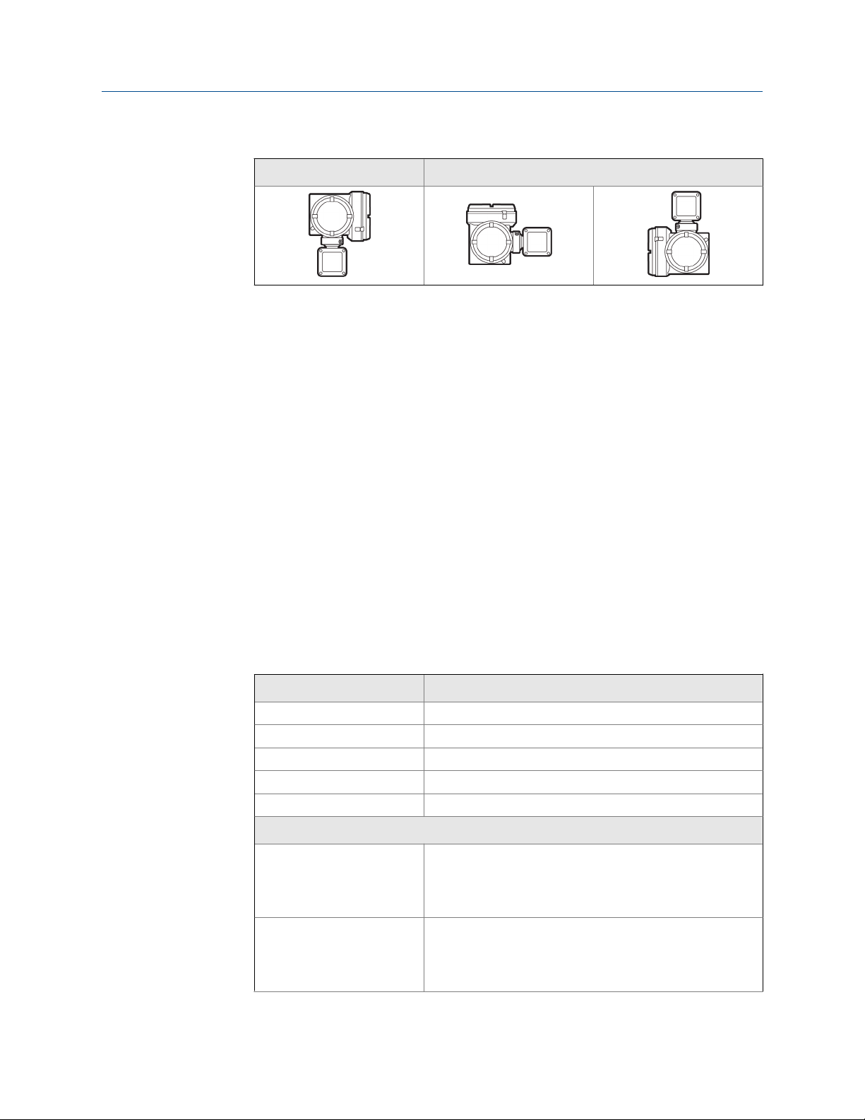
Possible transmitter orientationTable 1-2:
Preferred orientation Alternate orientations
Mount the meter in a location and orientation that satisfies the following conditions:
□
- Allows sufficient clearance to open the transmitter housing cover. Micro Motion
recommends 8–10 inches (200–250 mm) clearance at the wiring access points.
- Provides clear access for installing cabling to the transmitter.
1.4 Additional considerations for retrofitting existing installations
Planning
The transmitter installation may require 3–6 inches (76–153 mm) of additional
□
wiring for the input/output and power connections. This length would be in addition
to the currently installed wiring. Confirm you have the additional wiring necessary
for the new installation.
Before removing the existing transmitter, be sure to record the configuration data
□
for the currently installed transmitter. At initial startup of the newly installed
transmitter, you will be prompted to configure the meter via a guided setup.
Micro Motion recommends that you record the following information (if applicable):
Variable Setting
Tag
Mass flow units
Volume flow units
Density units
Temperature units
Channel configuration
mA output 1 - Power (Internal or External):
- Source:
- Scaling (LRV, URV):
- Fault Action:
mA output 2 (optional) - Power (Internal or External):
- Source:
- Scaling (LRV, URV):
- Fault Action:
Installation Manual 3
Page 8

M = 18V + (R × L × 0.7A)
Planning
Variable Setting
Frequency output (optional) - Power (Internal or External):
- Source:
- Scaling (LRV, URV):
- Fault Action:
- Dual output:
Discrete output (optional) - Power (Internal or External):
- Source:
- Scaling (LRV, URV):
- Fault Action:
Discrete input (optional) - Power (Internal or External):
- Source:
- Scaling (LRV, URV):
- Fault Action:
Calibration parameters (for 9-wire installations only)
Flow calibration factor - FCF (Flow Cal or Flow Calibration Factor):
Density calibration factors - D1:
- D2:
- K1:
- K2:
- TC:
- FD:
1.5 Power requirements
Self-switching AC/DC input, automatically recognizes supply voltage:
• 85 to 265 VAC, 6.5 watts typical, 9 watts maximum
• 18 to 100 VDC, 6.5 watts typical, 9 watts maximum
Note
For DC power:
• Power requirements assume a single transmitter per cable.
• At startup, the power source must provide a minimum of 1.5 amps of short-term current per
transmitter.
• Length and conductor diameter of the power cable must be sized to provide 18 VDC
minimum at the power terminals, at a load current of 0.7 amps.
Table sizing formula
• M: minimum supply voltage
• R: cable resistance
4 Micro Motion® Model 5700 Ethernet transmitters
Page 9

• L: cable length (in Ω/ft)
Typical power cable resistance at 68 °F (20 °C)
Wire gauge Resistance
14 AWG 0.0050 Ω/ft
16 AWG 0.0080 Ω/ft
18 AWG 0.0128 Ω/ft
20 AWG 0.0204 Ω/ft
2.5 mm
1.5 mm
1.0 mm
0.75 mm
0.50 mm
2
2
2
2
2
0.0136 Ω/m
0.0228 Ω/m
0.0340 Ω/m
0.0460 Ω/m
0.0680 Ω/m
Planning
1.5.1 Maximum cable lengths between sensor and transmitter
The maximum cable length between the sensor and transmitter that are separately
installed is determined by cable type.
Maximum cable lengths between sensor and transmitterTable 1-3:
Cable type Wire gauge Maximum length
Micro Motion 4-wire Not applicable • 1000 ft (300 m) without Ex-
approval
• 500 ft (150 m) with IIC rat-
ed sensors
• 1000 ft (300 m) with IIB rat-
ed sensors
Micro Motion 9-wire Not applicable 1000 ft (300 m)
User-supplied 4-wire VDC 22 AWG (0.35 mm2) 300 ft (90 m)
VDC 20 AWG (0.5 mm2) 500 ft (150 m)
VDC 18 AWG (0.8 mm2) 1000 ft (300 m)
RS-485 22 AWG (0.35 mm2) or
larger
1000 ft (300 m)
1.6 Model 5700 transmitters in Ethernet networks
You can install the Model 5700 transmitter in star, ring, or daisy-chain networks using
industrial-rated shielded Ethernet cables.
• Make sure that each cable is no longer than 100 meters.
Installation Manual 5
Page 10
Planning
• Connect the Model 5700 transmitter to the host system via a LAN (Local Area
Network) and not a WAN (Wide Area Network).
• Follow all network security best practices.
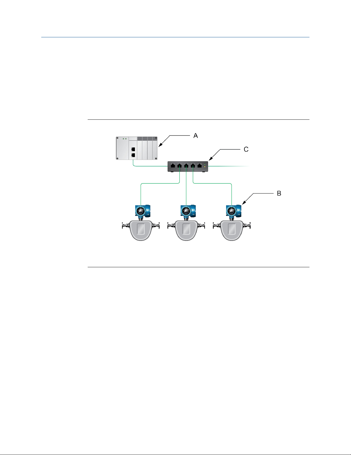
1.6.1 Star topology
Model 5700 transmitters can be installed in a star network.
Model 5700 star networkFigure 1-1:
A. Programmable Logic Controller (PLC)
B. Model 5700 with Ethernet output
C. External Ethernet switch
1.6.2 Ring topology
Model 5700 transmitters can be installed in a ring network.
6 Micro Motion® Model 5700 Ethernet transmitters
Page 11
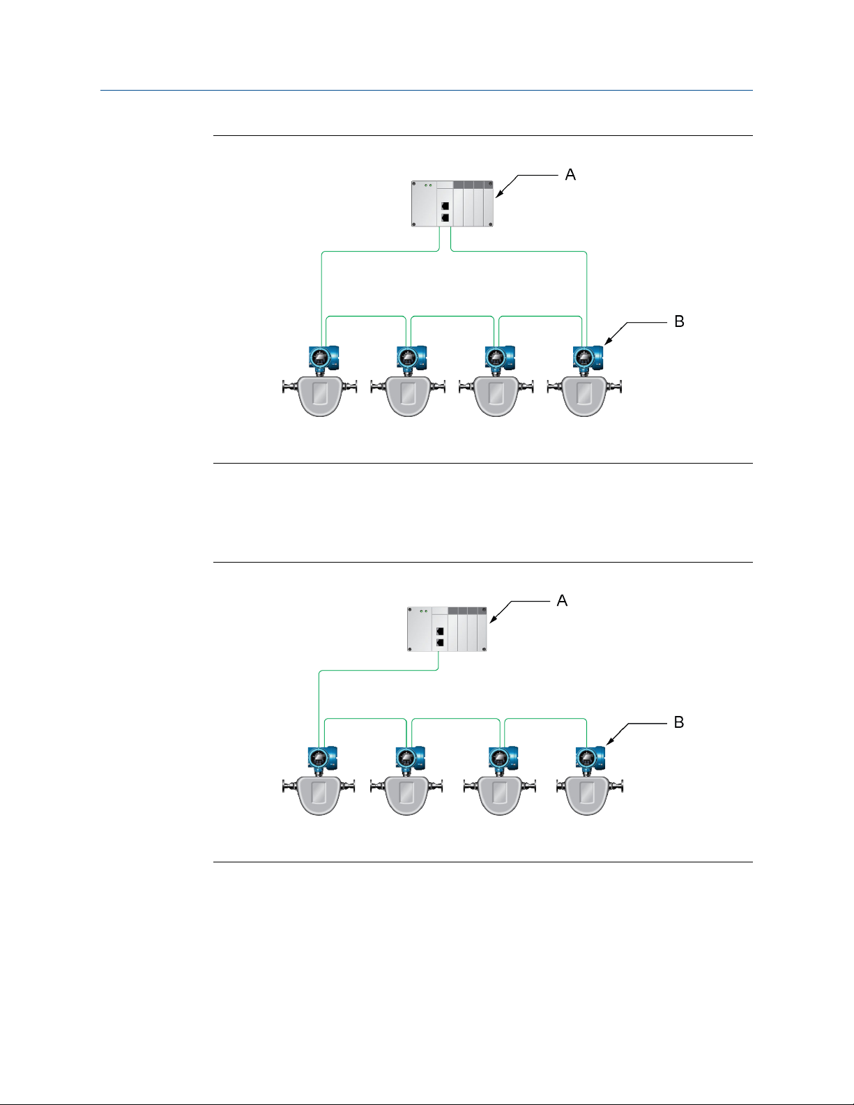
Model 5700 ring networkFigure 1-2:
A. Programmable Logic Controller (PLC)
B. Model 5700 with Ethernet output
Planning
1.6.3 Daisy-chain topology
Model 5700 transmitters can be installed in a daisy-chain network.
Model 5700 daisy-chain networkFigure 1-3:
A. Programmable Logic Controller (PLC)
B. Model 5700 with Ethernet output
Installation Manual 7
Page 12

Mounting and sensor wiring
2 Mounting and sensor wiring
Topics covered in this chapter:
• Mounting and sensor wiring for integral-mount transmitters
• Mount the 4-wire or 9-wire remote-mount transmitters
• Wire the 4-wire or 9-wire remote-mount transmitter to the sensor
• Ground the meter components
• Rotate the transmitter on the sensor (optional)
• Rotate the user interface on the transmitter (optional)
• Rotate the sensor wiring junction box on a remote-mount transmitter
(optional)
2.1 Mounting and sensor wiring for integralmount transmitters
There are no separate mounting requirements for integral transmitters, and no need to
connect wiring between the transmitter and the sensor.
2.2 Mount the 4-wire or 9-wire remote-mount
transmitters
2.2.1 Mount the transmitter to a wall or instrument pole
There are two options available for mounting the transmitter:
• Mount the transmitter to a wall or flat surface.
• Mount the transmitter to an instrument pole.
Prerequisites
• If you are mounting the transmitter to a wall or flat surface:
- Micro Motion recommends the use of 5/16-18 (M8X1.25) fasteners that can
withstand the process environment. Micro Motion does not supply bolts or nuts
as part of the standard offering (general purpose bolts and nuts are available as
an option).
- Ensure that the surface is flat and rigid, does not vibrate, or move excessively.
- Confirm that you have the necessary tools, and the mounting kit shipped with
the transmitter.
8 Micro Motion® Model 5700 Ethernet transmitters
Page 13
Mounting and sensor wiring
• If you are mounting the transmitter to an instrument pole:
- Ensure that the instrument pole extends at least 12 inches (305 mm) from a rigid
base, and is no more than 2 inches (50.8 mm) in diameter.
- Confirm that you have the necessary tools, and the instrument-pole mounting
kit shipped with the transmitter.
Procedure
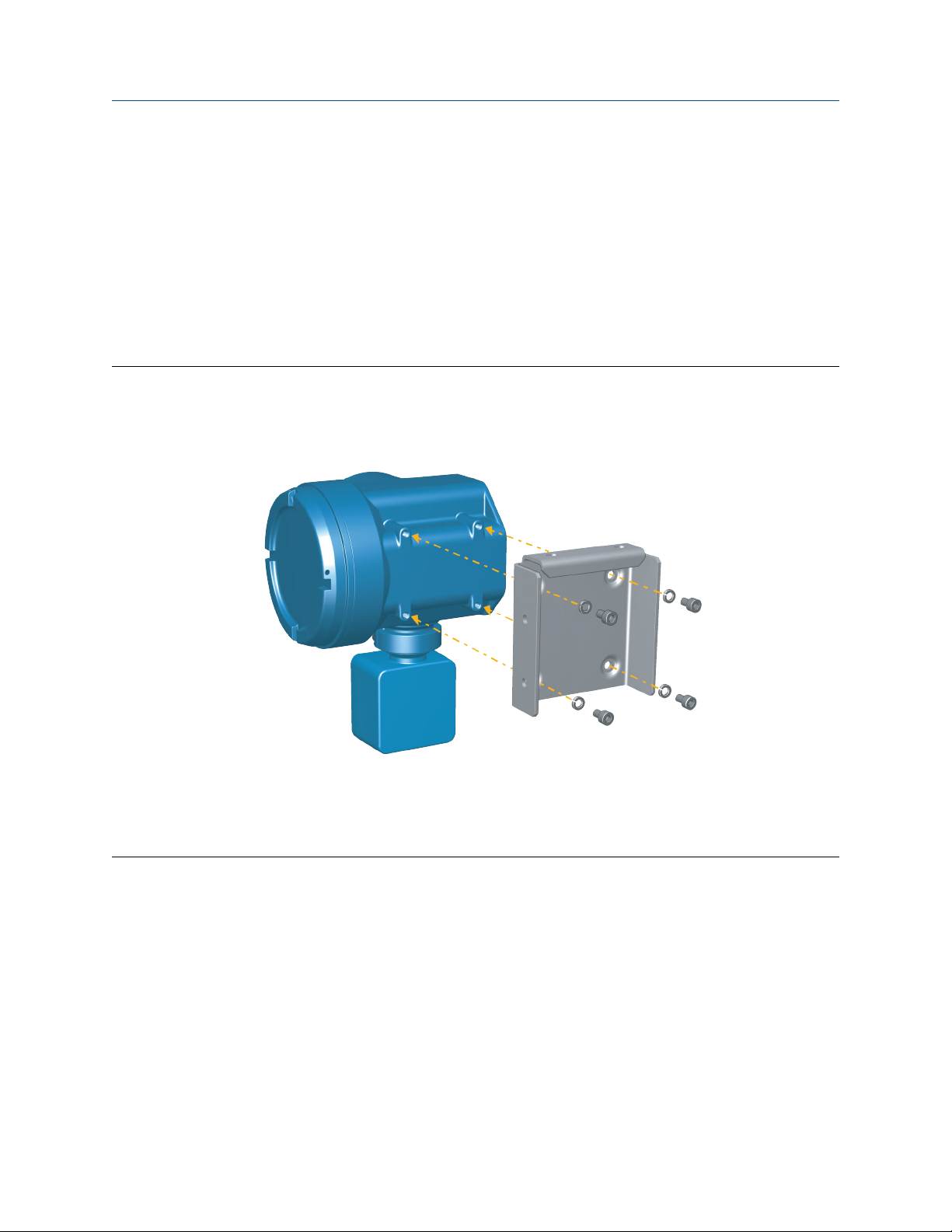
1. Attach the mounting bracket to the transmitter and tighten the screws to 80-90 inlbs.
Mounting bracket to transmitterFigure 2-1:
2. Using a wall-mount or pole-mount:
• For wall-mount installations, secure the mounting bracket to the prepared
surface.
Installation Manual 9
Page 14
Mounting and sensor wiring
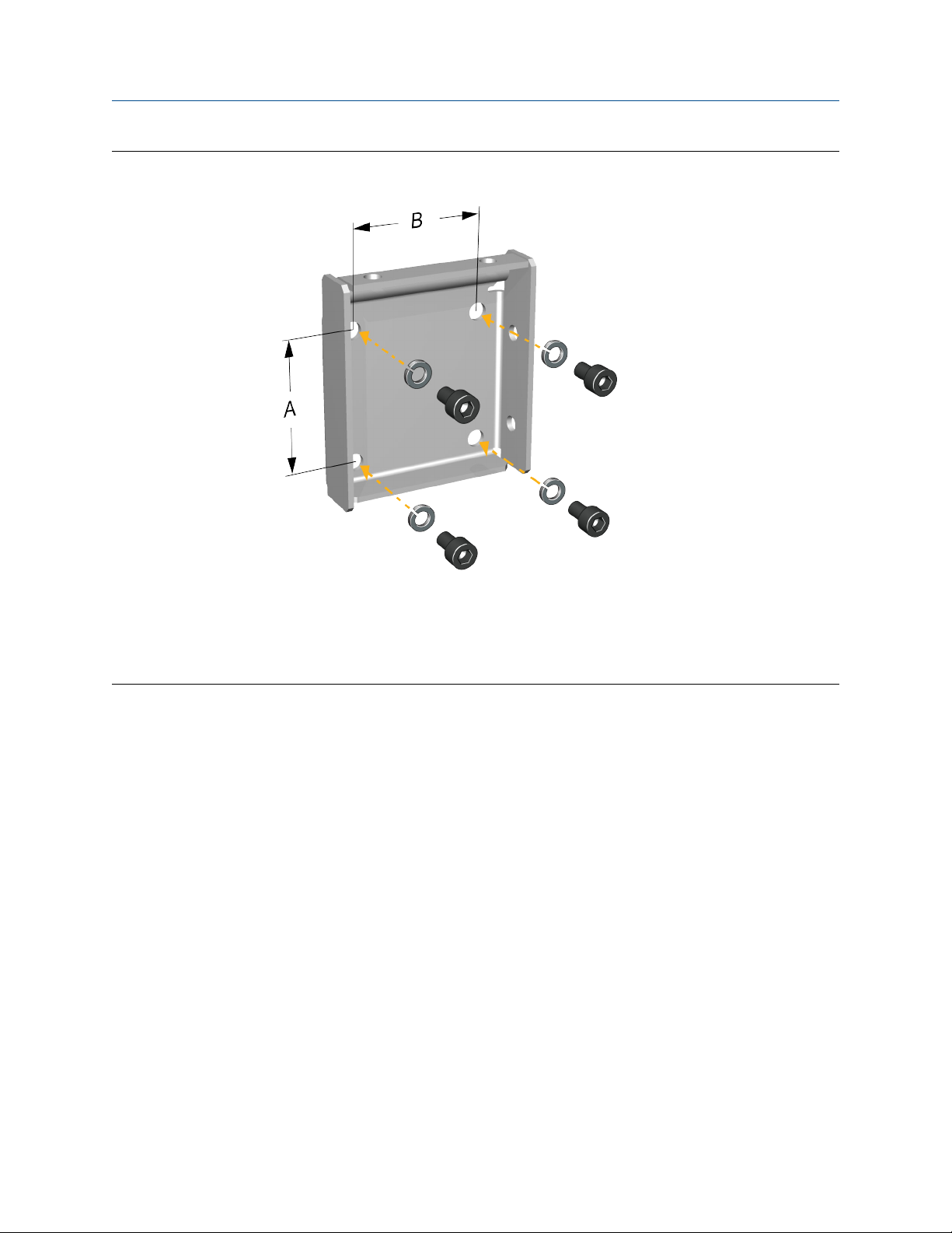
Wall-mounting bracket dimensionsFigure 2-2:
A. 2.8 in (71.4 mm)
B. 2.8 in (71.4 mm)
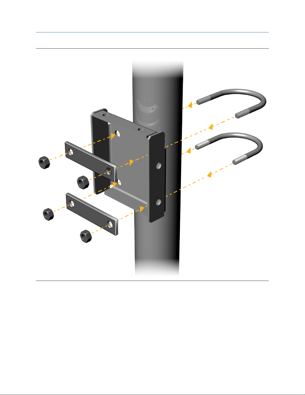
• For pole-mount installations, attach the U-bolt mounting piece to the
instrument pole.
10 Micro Motion® Model 5700 Ethernet transmitters
Page 15
Mounting and sensor wiring
Pole-mounting bracket attachmentFigure 2-3:
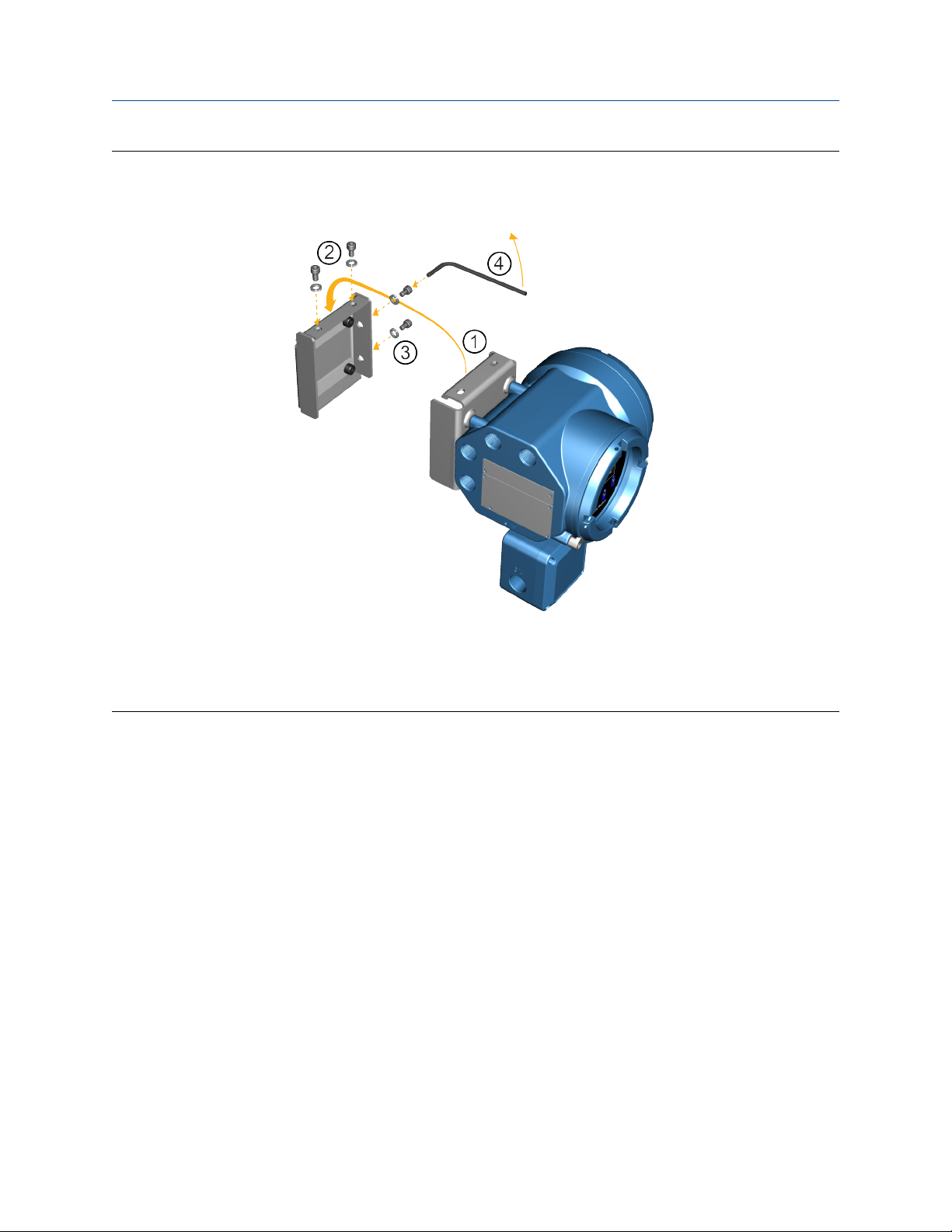
3. Place and attach the transmitter-mounting bracket to the mounting bracket
secured to the wall or instrument pole.
Installation Manual 11
Page 16
Mounting and sensor wiring
Attaching and securing transmitter to mounting bracketFigure 2-4:
Tip
To ensure the mounting bracket holes are aligned, insert all attachment bolts into place before tightening.
2.3 Wire the 4-wire or 9-wire remote-mount transmitter to the sensor
Prerequisites
• Prepare 4-wire or 9-wire cable as described in the sensor documentation.
• Connect the cable to the sensor-mounted core processor or junction box as
described in the sensor documentation. You can access all product documentation
online via the Micro Motion product documentation DVD shipped with the product
or at www.micromotion.com.
Procedure
1. Remove the transmitter-to-sensor wiring compartment cover to reveal the terminal
connections.
12 Micro Motion® Model 5700 Ethernet transmitters
Page 17
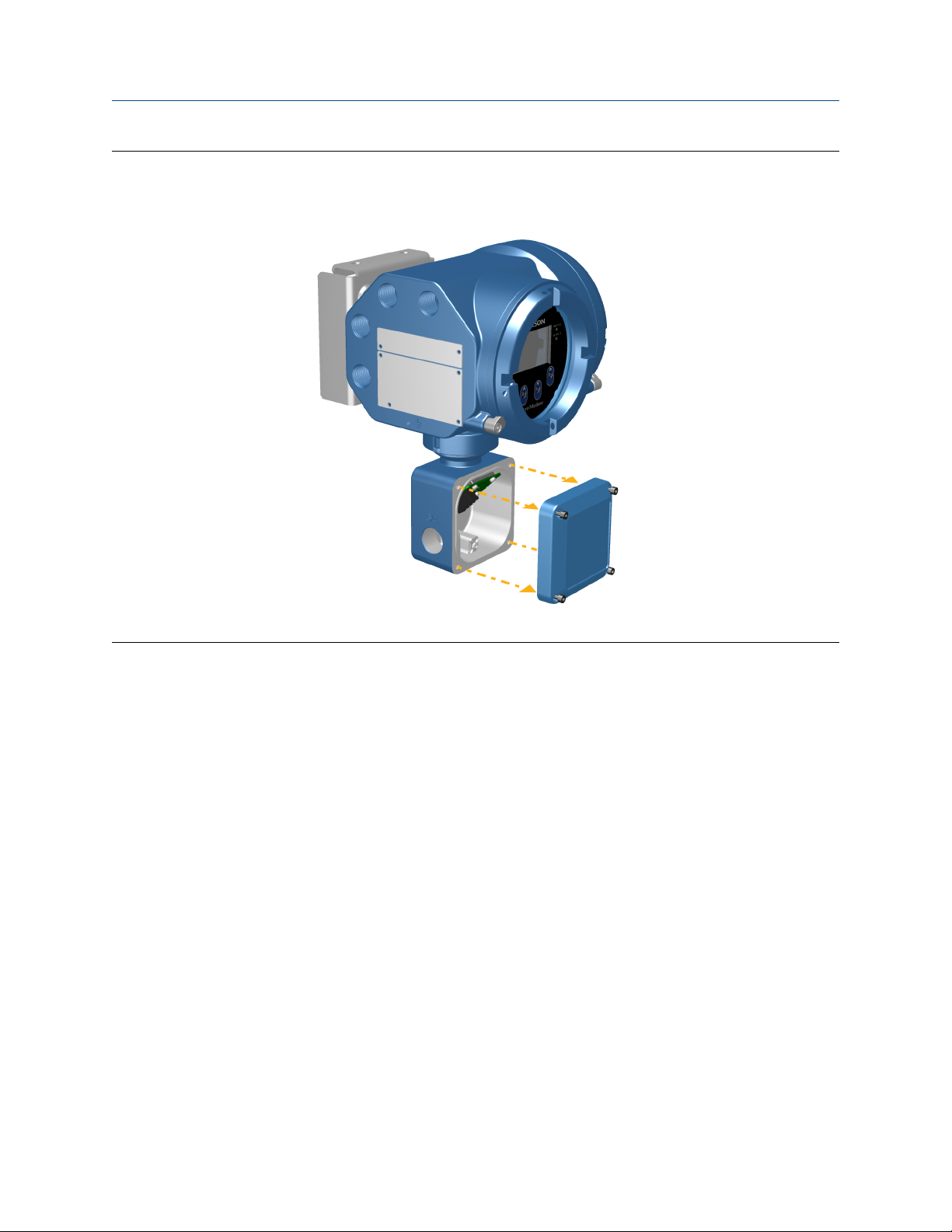
Mounting and sensor wiring
Removal of the transmitter-to-sensor wiring compartment coverFigure 2-5:
Installation Manual 13
Page 18

Mounting and sensor wiring
2. Feed the sensor wiring cable into the transmitter wiring compartment.
Sensor wiring feedthroughFigure 2-6:
3. Connect the sensor wires to the appropriate terminals.
Note
Terminate the 4-wire cable drain wires only at the sensor/core processor end of the cable. See
the sensor installation manual for more detail. Do not connect the 4-wire cable drain wires to
the ground screw located inside the 5700 junction box.
• See Figure 2-7 for 4-wire terminal connections.
• See Figure 2-8 for 9-wire terminal connections.
14 Micro Motion® Model 5700 Ethernet transmitters
Page 19

Mounting and sensor wiring
4-wire transmitter-to-sensor wiring connectionsFigure 2-7:
Installation Manual 15
Page 20

Mounting and sensor wiring
9-wire transmitter-to-sensor wiring connectionsFigure 2-8:
Note
Connect the 4 drain wires in the 9-wire cable to the ground screw located inside the junction box.
4. Replace the transmitter-to-sensor wiring compartment cover and tighten the
screws to 14-16 in-lbs.
2.4 Ground the meter components
In 4-wire or 9-wire remote installations, the transmitter and sensor are grounded
separately.
16 Micro Motion® Model 5700 Ethernet transmitters
Page 21

Mounting and sensor wiring
Prerequisites
CAUTION!
Improper grounding could cause inaccurate measurements or meter failure.
WARNING!
Failure to comply with requirements for intrinsic safety in a hazardous area could result in an
explosion.
Note
For hazardous area installations in Europe, refer to standard EN 60079-14 or national standards.
If national standards are not in effect, adhere to the following guidelines for grounding:
• Use copper wire, 14 AWG (2.5 mm2) or larger wire size.
• Keep all ground leads as short as possible, less than 1 Ω impedance.
• Connect ground leads directly to earth, or follow plant standards.
Procedure
1. Ground the sensor according to the instructions in the sensor documentation.
2. Ground the transmitter according to applicable local standards, using the
transmitter’s internal or external ground screw.
• The internal ground screw is located inside the transmitter-to-sensor wiring
compartment.
Installation Manual 17
Page 22

Mounting and sensor wiring
Internal ground screwFigure 2-9:
• The external ground screw is located on the side of the transmitter located below
the transmitter tag.
18 Micro Motion® Model 5700 Ethernet transmitters
Page 23

Mounting and sensor wiring
External ground screwFigure 2-10:
2.5 Rotate the transmitter on the sensor (optional)
In integral installations, you can rotate the transmitter on the sensor up to 360º in 45º
increments.
1. Using a 4 mm hex key, loosen and remove the clamp securing the transmitter head
in place.
Installation Manual 19
Page 24

Mounting and sensor wiring
Removal of the sensor clampFigure 2-11:
2. Gently lift the transmitter straight up, and rotate the transmitter to the desired
position.
You can rotate the transmitter to any of the eight positions, but a stop exists that
will not allow a full 360° rotation.
20 Micro Motion® Model 5700 Ethernet transmitters
Page 25

Mounting and sensor wiring
Rotation of the transmitter headFigure 2-12:
3. Gently lower the transmitter onto the base, confirming that the transmitter is in a
locked position.
4. Replace the clamp in its original position and tighten the cap screw. Torque to 28 to
30 in-lbs (2.3 to 3.4 N-m).
Installation Manual 21
Page 26

Mounting and sensor wiring
Re-attachment of the sensor clampFigure 2-13:
2.6 Rotate the user interface on the transmitter (optional)
The user interface on the transmitter electronics module can be rotated 90°, 180°, or 270°
from the original position.
22 Micro Motion® Model 5700 Ethernet transmitters
Page 27

Mounting and sensor wiring
Display componentsFigure 2-14:
A. Transmitter housing
B. Sub-bezel
C. Display module
D. Display screws
E. End-cap clamp
F. Cap screw
G. Display cover
Procedure
1. Shut off power to the unit.
WARNING!
If the transmitter is in a hazardous area, wait five minutes after disconnecting the power
before opening the enclosure.
2. Loosen and rotate the end cap clamp so that it does not interfere with the cover.
3. Turn the display cover counterclockwise to remove it from the main enclosure.
Installation Manual 23
Page 28

Mounting and sensor wiring
4. Carefully loosen the semi-captive display screws while holding the display module in
place.
5. Carefully pull the display module out of the main enclosure.
6. Rotate the display module to the desired position.
7. Gently press the display module back onto the connector.
8. Tighten display screws.
9. Place the display cover onto the main enclosure.
10. Turn the display cover clockwise until it is fully seated.
11. Replace the end-cap clamp by tightening the cap screw.
12. Restore power to the transmitter.
2.7 Rotate the sensor wiring junction box on a remote-mount transmitter (optional)
In remote-mount installations, you can rotate the sensor wiring junction box on the
transmitter plus or minus 180º.
1. Using a 4 mm hex key, loosen and remove the clamp securing the sensor wiring
junction box in place.
24 Micro Motion® Model 5700 Ethernet transmitters
Page 29

Mounting and sensor wiring
Removal of the clampFigure 2-15:
2. Gently rotate the junction box to the desired position.
You can rotate the junction box plus or minus 180º to any position.
Installation Manual 25
Page 30

Mounting and sensor wiring
Rotation of the sensor wiring junction boxFigure 2-16:
3. Gently set the junction box into its new position, confirming that the position is
locked.
4. Replace the clamp in its original position and tighten the cap screw. Torque to 28 to
30 in-lbs (2.3 to 3.4 N-m).
26 Micro Motion® Model 5700 Ethernet transmitters
Page 31

Mounting and sensor wiring
Re-attachment of the clampFigure 2-17:
Installation Manual 27
Page 32

Wiring the channels
3 Wiring the channels
Topics covered in this chapter:
• Wire the I/O channel
• Wire the Ethernet channels
3.1 Wire the I/O channel
The Channel C I/O can be configured as:
• mA Output
• Frequency Output
• Discrete Output
• Discrete Input
3.1.1 Access the wiring channels
Remove the wiring access cover to reveal the I/O wiring terminal block connectors.
3.1.2 Wire the mA Output
Wire the mA Output for explosion-proof, nonincendive, or nonhazardous installations.
28 Micro Motion® Model 5700 Ethernet transmitters
Page 33

A
D
C
B
A
E
D
C
B
Wiring the channels
Prerequisites
Important
Meter installation and wiring should be performed only by suitably-trained personnel using the
appropriate government and corporate safety standards.
Procedure
Wire to the appropriate output terminal and pins.
Internally-powered mA Output wiringFigure 3-1:
A. mA Output
B. Channel C
C. 820 Ω maximum loop resistance
D. Signal device
Externally-powered mA Output wiringFigure 3-2:
A. mA Output
B. Channel C
C. 5–30 VDC (maximum)
D. See Figure 3-3
E. Signal device
Installation Manual 29
Page 34

0
100
200
300
400
500
600
700
800
900
1000
1100
0 7.5 15.0 22.5 30.0
B
A
Wiring the channels
Externally-powered mA Output: maximum loop resistanceFigure 3-3:
A. Maximum resistance (Ω)
B. External supply voltage (V)
3.1.3 Wire the Frequency Output
Wire the Frequency Output in explosion-proof, nonincendive, or nonhazardous
installations.
Prerequisites
Important
Meter installation and wiring should be performed only by suitably-trained personnel using the
appropriate government and corporate safety standards.
Procedure
Wire to the appropriate output terminal and pins.
30 Micro Motion® Model 5700 Ethernet transmitters
Page 35

Internally-powered FO wiringFigure 3-4:
A
D
C
B
0
2
4
6
8
10
12
14
16
18
20
22
24
0 250 500 750 1000
A
B
A. Frequency Output
B. Channel C
C. See Figure 3-5
D. Counter
Wiring the channels
Figure 3-5:
Internally-powered FO: output amplitude versus load resistance [24 VDC
(Nom) open circuit]
A. Output amplitude (V)
B. Load resistor (Ω)
Installation Manual 31
Page 36

A
B
E
D
C
A
D
C
B
Wiring the channels
Externally-powered FO wiringFigure 3-6:
A. Frequency Output
B. Channel C
C. 5–30 VDC (maximum)
D. 500 mA current (maximum)
E. Counter
3.1.4 Wire the Discrete Output
Wire the Discrete Output in explosion-proof, nonincendive, or nonhazardous installations.
Prerequisites
Important
Meter installation and wiring should be performed only by suitably-trained personnel using the
appropriate government and corporate safety standards.
Procedure
Wire to the appropriate output terminal and pins.
Internally-powered DO wiringFigure 3-7:
A. Discrete Output
B. Channel C
C. See Figure 3-8
D. Counter
32 Micro Motion® Model 5700 Ethernet transmitters
Page 37

0
2
4
6
8
10
12
14
16
18
20
22
24
0 750 1500 2250 3000
A
B
A
B
E
D
C
Wiring the channels
Figure 3-8:
Internally-powered DO: output amplitude versus load resistance [24 VDC
(Nom) open circuit]
A. Output amplitude (V)
B. Load resistor (Ω)
Externally-powered DO wiringFigure 3-9:
A. Discrete Output
B. Channel C
C. 3–30 VDC (maximum)
D. 500 mA current (maximum)
E. Counter
Installation Manual 33
Page 38

A
C
B
A
C
B
Wiring the channels
3.1.5 Wire the Discrete Input
Prerequisites
CAUTION!
Wire the Discrete Input in explosion-proof, nonincendive, or nonhazardous installations.
Important
Meter installation and wiring should be performed only by suitably-trained personnel using the
appropriate government and corporate safety standards.
Procedure
Wire to the appropriate input terminal and pins.
Internally-powered DI wiringFigure 3-10:
A. Discrete input
B. Channel C
C. Switch
Externally-powered DI wiringFigure 3-11:
A. Discrete input
B. Channel C
C. 30 VDC (maximum)
Note
• Maximum positive threshold is 3 VDC.
• Minimum negative threshold is 0.6 VDC.
34 Micro Motion® Model 5700 Ethernet transmitters
Page 39

Wiring the channels
3.1.6 Wire the I/O channel using an M12-terminated cable (optional)
Use this procedure if you are using an M12-terminated cable to wire the I/O channel.
Prerequisites
Obtain an A-coded M12-terminated cable.
Procedure
1. Attach the M12-terminated cable to the configuration I/O connector on the Model
5700 transmitter. See Figure 3-12.
2. Attach the other cable end using the pinouts described in Table 3-1.
M12-terminated cables to the Configuration I/OFigure 3-12:
M12 configuration I/O pinoutsTable 3-1:
Pin identification Wire color Outputs
Pin 1 Not used Not used
Pin 2 White Positive terminal
Pin 3 Not used Not used
Pin 4 Black Neutral terminal
Installation Manual 35
Page 40

Wiring the channels
3.2 Wire the Ethernet channels
To meet the EC Directive for Electromagnetic Compatibility (EMC), use a suitable shielded
Cat5e, or higher-rated instrumentation cable to connect the meter. The instrumentation
cable should have an overall screen to cover all cores. Where permissible, connect the
overall screen to earth at the host end (360° bonded).
3.2.1 Wire an Ethernet network using the RJ45 ports
Prerequisites
When using a pre-terminated RJ45 cable, ensure there is no protective boot on the
connector, as a protective boot will not fit through the conduit. Alternatively, you can use
the RJ45 connector using a shielded-field termination connector.
Direct connection and star topology
1. Feed the RJ45 cable through the conduit on the Model 5700 transmitter.
2. Connect the RJ45 cable into either Channel A or Channel B.
Functionality is identical for both Channel A and Channel B as the Model 5700
transmitter contains an internal Ethernet switch.
3. Anchor the cable to the module backplate using a cable tie.
Example:
36 Micro Motion® Model 5700 Ethernet transmitters
Page 41

Wiring the channels
Daisy chain and ring topologies
1. Feed two RJ45 cables through the conduits on the Model 5700 transmitter.
Since two cables will not fit into one conduit, you will need to use separate conduits
for each cable.
2. Connect the external switch or previous transmitter to Channel A or Channel B.
Functionality is identical for both Channel A and Channel B as the Model 5700
transmitter contains an internal Ethernet switch.
3. Connect the next transmitter in the network to the unused channel.
4. Anchor the cables to the module backplate using cable ties.
Example:
Installation Manual 37
Page 42

Wiring the channels
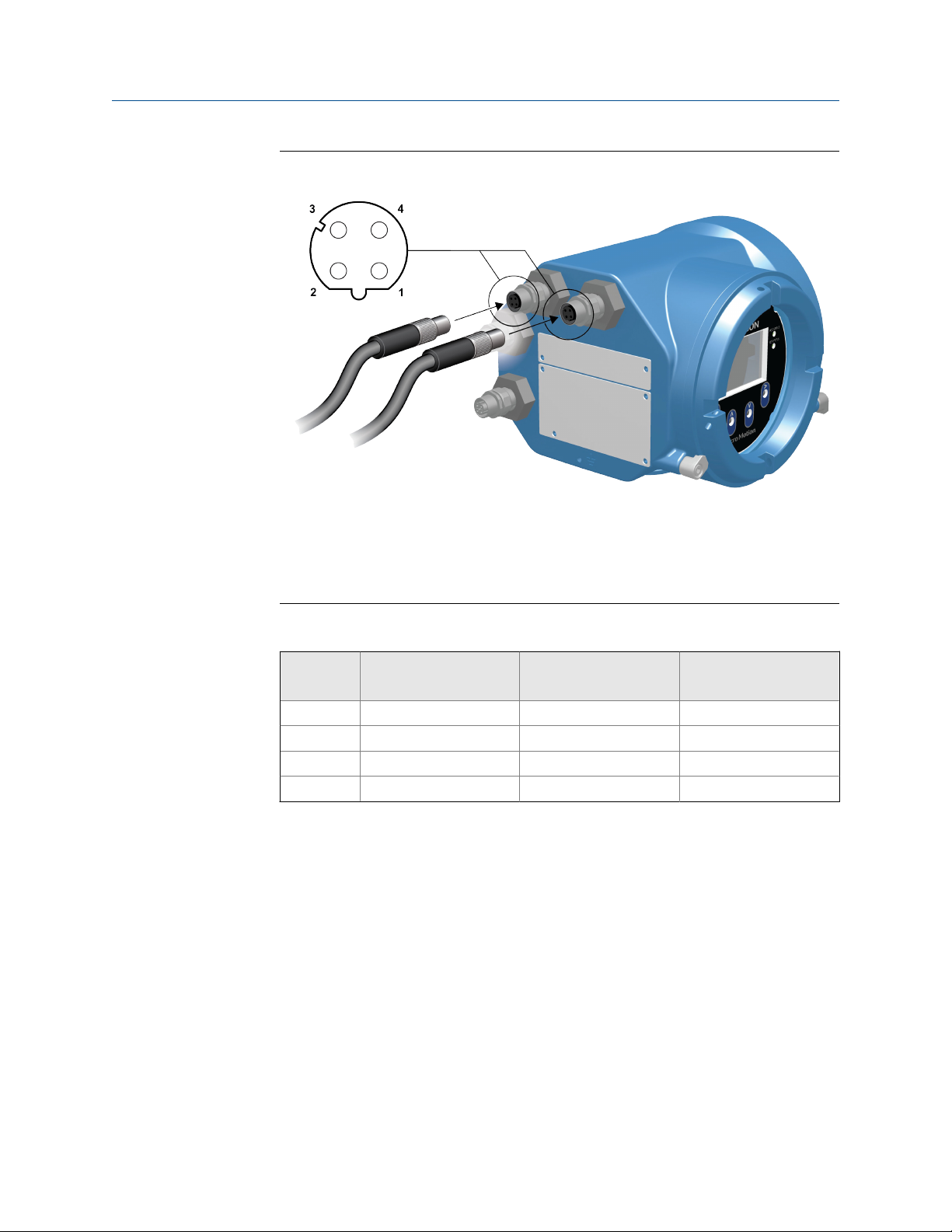
3.2.2 Wire the Ethernet I/O using M12-terminated cables (optional)
Prerequisites
Obtain two D-coded M12-terminated Ethernet cables.
Procedure
1. Attach both M12-terminated Ethernet cables to the Ethernet I/O connectors on the
Model 5700 transmitter. See Figure 3-13.
2. Attach the other cable end using the pinouts described in Table 3-2.
38 Micro Motion® Model 5700 Ethernet transmitters
Page 43
Wiring the channels
M12 cables to the Ethernet I/OFigure 3-13:
Note
Depending on what type of M12 Ethernet option you have, your transmitter may have only the two
Ethernet I/O connectors.
M12 Ethernet I/O pinoutsTable 3-2:
Pin identification Wire color Outputs on RJ45 Signal name
Pin 1 Orange/White Pin 1 TDP1/RDP2
Pin 2 Green/White Pin 3 RDP1/TDP2
Pin 3 Orange Pin 2 TDN1/RDN2
Pin 4 Green Pin 6 RDN1/RDN2
Installation Manual 39
Page 44

Power supply wiring
4 Power supply wiring
Topics covered in this chapter:
• Wiring the power supply
• Wire the power supply using an M12-terminated cable (optional)
4.1 Wiring the power supply
You can install a user-supplied switch in the power supply line.
Important
For compliance with the Low Voltage Directive 2014/35/EU (European installations), a switch in close
proximity to the transmitter is required.
Procedure
1. Remove the wiring access cover.
2. Open the Power warning flap to locate the power terminals.
40 Micro Motion® Model 5700 Ethernet transmitters
Page 45

Power supply wiring
Location of power supply wiring terminals and equipment groundFigure 4-1:
A. Power supply wiring terminals (+ and -)
B. Equipment ground
3. Connect the power supply wires:
• For DC power: connect to terminals + and –.
• For AC power: connect to terminals L/L1 (line) and N/L2 (neutral).
4. Tighten the two screws holding the power connector in place.
5. Ground the power supply using the equipment ground, also under the Power
warning flap.
4.2 Wire the power supply using an M12terminated cable (optional)
Use this procedure if you are using an M12-terminated cable to wire the power supply.
Installation Manual 41
Page 46

Power supply wiring
Prerequisites
Obtain an S-coded M12-terminated cable.
Procedure
1. Attach the M12-terminated cable to the power connector on the Model 5700
transmitter. See Figure 4-2.
2. Attach the other cable end using the pinouts described in Table 4-1.
M12-terminated cable to power supplyFigure 4-2:
M12 power supply pinoutsTable 4-1:
Pin identification Outputs
Pin 1 + / L / L1
Pin 2 - / N / L2
Pin 3 Not used
Ground Ring terminal (C)
42 Micro Motion® Model 5700 Ethernet transmitters
Page 47

5 Power up the transmitter
The transmitter must be powered up for all configuration and commissioning tasks, or for
process measurement.
1. Ensure that all transmitter and sensor covers and seals are closed.
WARNING!
To prevent ignition of flammable or combustible atmospheres, ensure that all covers
and seals are tightly closed. For hazardous area installations, applying power while
housing covers are removed or loose can cause an explosion.
2. Turn on the electrical power at the power supply.
Postrequisites
Although the sensor is ready to receive process fluid shortly after power-up, the electronics
can take up to 10 minutes to reach thermal equilibrium. Therefore, if this is the initial
startup, or if power has been off long enough to allow components to reach ambient
temperature, allow the electronics to warm up for approximately 10 minutes before
relying on process measurements. During this warm-up period, you may observe minor
measurement instability or inaccuracy.
Power up the transmitter
Installation Manual 43
Page 48

Guided Setup
6 Guided Setup
At initial startup of the transmitter, the guided configuration screen appears on the
transmitter display. This tool guides you through basic configuration of the transmitter.
The guided setup allows you to upload configuration files, set the transmitter display
options, configure channels, and review sensor calibration data.
44 Micro Motion® Model 5700 Ethernet transmitters
Page 49

7 Using the Display controls
The transmitter display interface includes a display (LCD panel) and four optical switches –
left, up, down, and right arrow keys – used to access the display menus and navigate the
display screens.
1. To activate an optical switch, block the light by holding your thumb or finger in front
of the opening.
You can activate the optical switch through the lens. Do not remove the transmitter
housing cover.
Important
The transmitter only detects one switch selection at a time. Be sure to place your thumb or
finger directly over a single optical switch, and ensure no other switches are being obstructed.
Using the Display controls
Installation Manual 45
Page 50

Using the Display controls
Proper finger positioning for activating an optical switchFigure 7-1:
2. Use the arrow indicators on the display screen to identify which optical switch to use
to navigate the screen (see examples 1 and 2).
Important
When using the arrow keys, you must first activate the optical switch then release the same
switch by removing your finger from the glass to move up, down, right, left or to make a
selection. To enable auto-scroll when navigating up or down, activate the appropriate switch
and continue to hold for one second. Release the switch when the desired selection is
highlighted.
46 Micro Motion® Model 5700 Ethernet transmitters
Page 51

Using the Display controls
Example 1: Active arrow indicators on the transmitter displayFigure 7-2:
Installation Manual 47
Page 52

Using the Display controls
Example 2: Active arrow indicators on the transmitter displayFigure 7-3:
48 Micro Motion® Model 5700 Ethernet transmitters
Page 53

Available Service Port connection
8 Available Service Port connection
You can interface with the transmitter through the service port connection, located under
the transmitter cap.
To interface with the service port, you can use commonly available USB hardware, such as
a USB drive or USB cable. Use the service port connection to download or upload data
from/to the transmitter.
Note
The USB drive must be in FAT format. The transmitter does not recognize NTFS format.
WARNING!
If the transmitter is in a hazardous area, do not remove the housing cover while power is being
supplied to the unit. Removing the housing cover while power is supplied to the unit could
cause an explosion. To access the service port in a hazardous environment, be sure to remove
power from the transmitter and wait 5 minutes before removing the housing cover.
Installation Manual 49
Page 54

Micro Motion Inc. USA
Worldwide Headquarters
7070 Winchester Circle
Boulder, Colorado 80301
T +1 303-527-5200
T +1 800-522-6277
F +1 303-530-8459
www.micromotion.com
Micro Motion Europe
Emerson Process Management
Neonstraat 1
6718 WX Ede
The Netherlands
T +31 (0) 70 413 6666
F +31 (0) 318 495 556
www.micromotion.nl
*MMI-20029768*
MMI-20029768
Rev AA
2016
Micro Motion Asia
Emerson Process Management
1 Pandan Crescent
Singapore 128461
Republic of Singapore
T +65 6777-8211
F +65 6770-8003
Micro Motion United Kingdom
Emerson Process Management Limited
Horsfield Way
Bredbury Industrial Estate
Stockport SK6 2SU U.K.
T +44 0870 240 1978
F +44 0800 966 181
Micro Motion Japan
Emerson Process Management
1-2-5, Higashi Shinagawa
Shinagawa-ku
Tokyo 140-0002 Japan
T +81 3 5769-6803
F +81 3 5769-6844
©
2016 Micro Motion, Inc. All rights reserved.
The Emerson logo is a trademark and service mark of Emerson
Electric Co. Micro Motion, ELITE, ProLink, MVD and MVD Direct
Connect marks are marks of one of the Emerson Process
Management family of companies. All other marks are property of
their respective owners.
 Loading...