

Page 1

Installation Manual
P/N 3300991, Rev. C
November 2003
Micro Motion
Series 3000
Installation Manual
®
Micro Motion
TM
Page 2

Page 3

Micro Motion
®
Series 3000
Installation Manual
For online technical support, refer to the EXPERT2™ tool at
www.expert2.com. To speak to a customer service
representative, call the support center nearest you:
• In U.S.A., phone 1-800-522-MASS (1-800-522-6277)
• In Canada and Latin America, phone (303) 530-8400
• In Asia, phone (65) 6770-8155
• In the U.K., phone 0800 - 966 180 (toll-free)
• Outside the U.K., phone +31 (0) 318 495 670
©2003, Micro Motion, Inc. All rights reserved. Micro Motion is a registered trademark
of Micro Motion, Inc. The Micro Motion and Emerson logos are trademarks of
Emerson Electric Co. All other trademarks are property of their respective owners.
Page 4

Page 5

Contents
1 Before You Begin . . . . . . . . . . . . . . . . . . . . . . 1
1.1 About this manual . . . . . . . . . . . . . . . . . . . . . . . . . . . . . . 1
1.1 Safety. . . . . . . . . . . . . . . . . . . . . . . . . . . . . . . . . . . . . . . . 1
1.2 European installations . . . . . . . . . . . . . . . . . . . . . . . . . . . 2
1.2 Symbols . . . . . . . . . . . . . . . . . . . . . . . . . . . . . . . . . . . . . . 2
2 Installing the Model 3300 or 3500 in a Panel . . . 3
2.1 About this chapter . . . . . . . . . . . . . . . . . . . . . . . . . . . . . . 3
2.2 Hazardous area installations . . . . . . . . . . . . . . . . . . . . . . 3
2.3 Procedure for mounting in a panel . . . . . . . . . . . . . . . . . . 3
3 Installing the Model 3300 or 3500
in a Subrack. . . . . . . . . . . . . . . . . . . . . . . . . 15
3.1 About this chapter . . . . . . . . . . . . . . . . . . . . . . . . . . . . . 15
3.2 Hazardous area installations . . . . . . . . . . . . . . . . . . . . . 15
3.3 Procedure for mounting in subrack . . . . . . . . . . . . . . . . 15
4 Installing the Model 3350 or 3700 . . . . . . . . . . 23
4.1 About this chapter . . . . . . . . . . . . . . . . . . . . . . . . . . . . . 23
4.2 Hazardous area classifications . . . . . . . . . . . . . . . . . . . 23
4.3 Procedure for field mounting . . . . . . . . . . . . . . . . . . . . . 23
5 Connecting the Transmitter to a Sensor . . . . . . 33
5.1 About this chapter . . . . . . . . . . . . . . . . . . . . . . . . . . . . . 33
5.2 Cable types . . . . . . . . . . . . . . . . . . . . . . . . . . . . . . . . . . 34
5.3 Cable and conduit preparation. . . . . . . . . . . . . . . . . . . . 34
5.4 Wiring connections to sensor. . . . . . . . . . . . . . . . . . . . . 37
5.5 Wiring connections to transmitter. . . . . . . . . . . . . . . . . . 37
6 Installing Relays. . . . . . . . . . . . . . . . . . . . . . 43
6.1 About this chapter . . . . . . . . . . . . . . . . . . . . . . . . . . . . . 43
6.2 Specifications for user-supplied relays. . . . . . . . . . . . . . 43
6.3 Hazardous area installations . . . . . . . . . . . . . . . . . . . . . 43
6.4 Replacing relays. . . . . . . . . . . . . . . . . . . . . . . . . . . . . . . 44
6.5 Software configuration . . . . . . . . . . . . . . . . . . . . . . . . . . 44
6.6 Installing factory-supplied relays . . . . . . . . . . . . . . . . . . 45
6.7 Installing user-supplied relays . . . . . . . . . . . . . . . . . . . . 50
6.8 Discrete output configuration . . . . . . . . . . . . . . . . . . . . . 53
Series 3000 Installation Manual i
Page 6

Contents continued
7 Printer Setup . . . . . . . . . . . . . . . . . . . . . . . . 55
7.1 About this chapter . . . . . . . . . . . . . . . . . . . . . . . . . . . . . 55
8 Startup . . . . . . . . . . . . . . . . . . . . . . . . . . . . 61
8.1 Startup and display test . . . . . . . . . . . . . . . . . . . . . . . . . 61
8.2 Configuration mode . . . . . . . . . . . . . . . . . . . . . . . . . . . . 62
8.3 Sensor zero . . . . . . . . . . . . . . . . . . . . . . . . . . . . . . . . . . 63
8.4 Fault outputs . . . . . . . . . . . . . . . . . . . . . . . . . . . . . . . . . 65
8.5 Alarm messages . . . . . . . . . . . . . . . . . . . . . . . . . . . . . . 66
8.6 Repair and substitution of components . . . . . . . . . . . . . 66
8.7 Customer service. . . . . . . . . . . . . . . . . . . . . . . . . . . . . . 66
Appendix A Specifications . . . . . . . . . . . . . . . . . . 67
Model 3300 . . . . . . . . . . . . . . . . . . . . . . . . . . . . . . . . . . . . . . . . . . 67
Model 3350 . . . . . . . . . . . . . . . . . . . . . . . . . . . . . . . . . . . . . . . . . . 71
Model 3500 . . . . . . . . . . . . . . . . . . . . . . . . . . . . . . . . . . . . . . . . . . 75
Model 3700 . . . . . . . . . . . . . . . . . . . . . . . . . . . . . . . . . . . . . . . . . . 79
Model 3100 accessory . . . . . . . . . . . . . . . . . . . . . . . . . . . . . . . . . 83
Appendix B Optional Housing Dimensions . . . . . . . 85
Appendix C Labels . . . . . . . . . . . . . . . . . . . . . . . 91
Appendix D Return Policy . . . . . . . . . . . . . . . . . . 93
Index . . . . . . . . . . . . . . . . . . . . . . . . . . . . . . . . 95
ii Series 3000 Installation Manual
Page 7
1 Before You Begin
1.1 About this manual This instruction manual explains how to install the Micro Motion
3000 Applications Platform.
Chapters • Chapter 2 explains how to mount the Model 3300 application
peripheral or Model 3500 transmitter in a panel.
• Chapter 3 explains how to mount the Model 3300 application
peripheral or Model 3500 transmitter in a 19-inch (486,2 mm)
subrack.
• Chapter 4 explains how to mount the Model 3350 application
peripheral or Model 3700 transmitter.
• Chapter 5 explains how to connect the Model 3500 or 3700
transmitter to a Micro Motion
• Chapter 6 explains how to connect internally or externally powered
relays to the discrete outputs.
• Chapter 7 explains how to set up the applications platform to send a
ticket to a printer.
• Chapter 8 explains startup procedures.
®
flow and density sensor.
Appendixes • Appendix A lists specifications.
• Appendix B provides dimensions for NEMA housing options.
• Appendix C shows labels on the applications platform.
• Appendix D is the return goods policy.
®
Series
Installation: Panel-Mount Installation: Field-MountInstallation: Rack-MountBefore You Begin
1.1 Safety Safety messages are provided throughout this manual to protect
personnel and equipment. Read each safety message carefully before
proceeding to the next step.
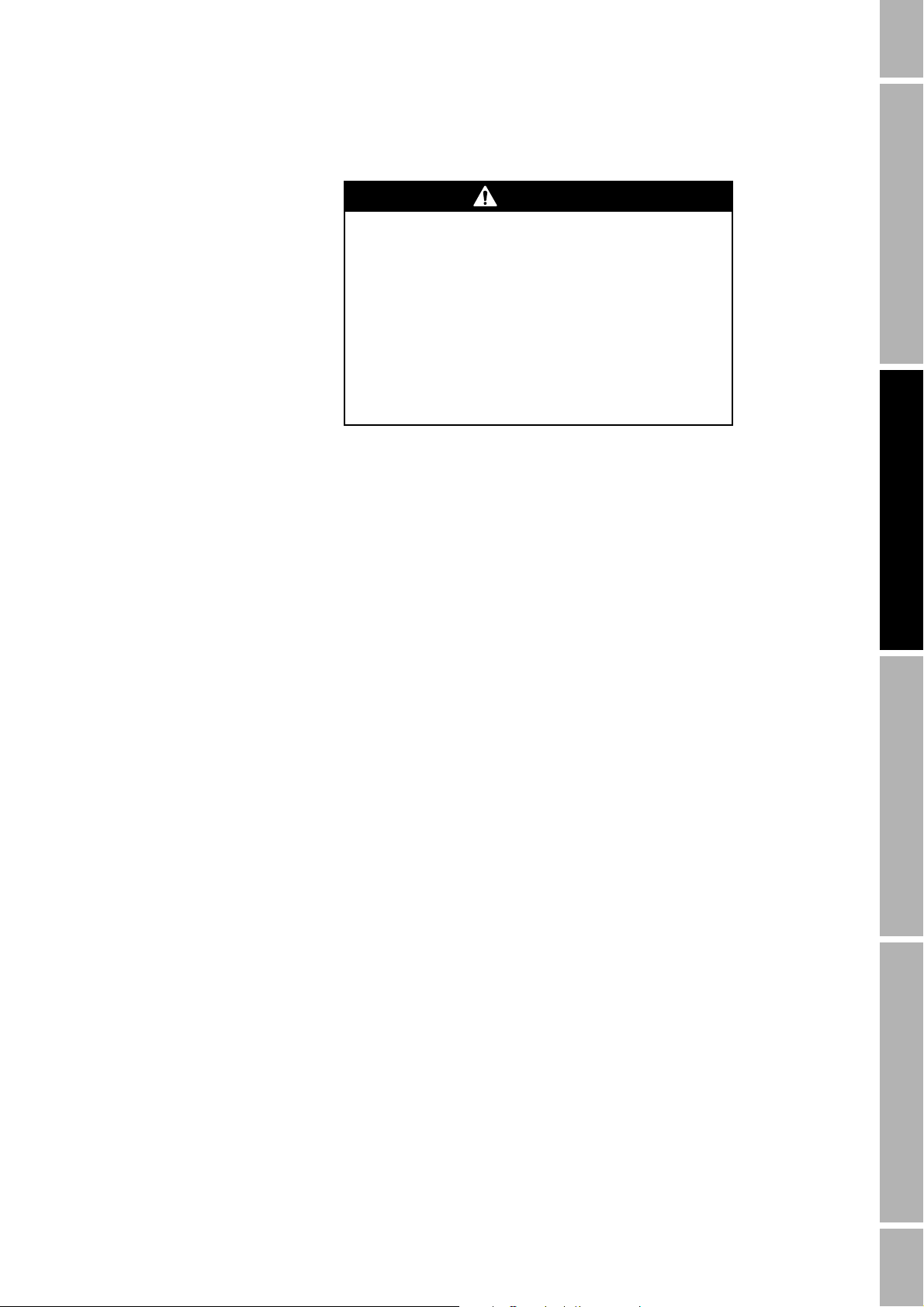
WARNING
Improper installation in a hazardous area can cause
an explosion.
For information about hazardous applications, refer to
Micro Motion ATEX, UL, or CSA installation instructions,
shipped with the applications platform or available from
the Micro Motion web site.
CAUTION
Improper installation could cause measurement error
or flowmeter failure.
Follow all instructions to ensure applications platform will
operate correctly.
Series 3000 Installation Manual 1
Page 8
Before You Begin continued
1.2 European installations This Micro Motion product complies with all applicable European
directives when properly installed in accordance with the instructions in
this manual. Refer to the EC declaration of conformity for directives that
apply to this product.
The EC declaration of conformity, with all applicable European
directives, and the complete ATEX Installation Drawings and Instructions
are available on the internet at www.micromotion.com/atex or through
your local Micro Motion support center.
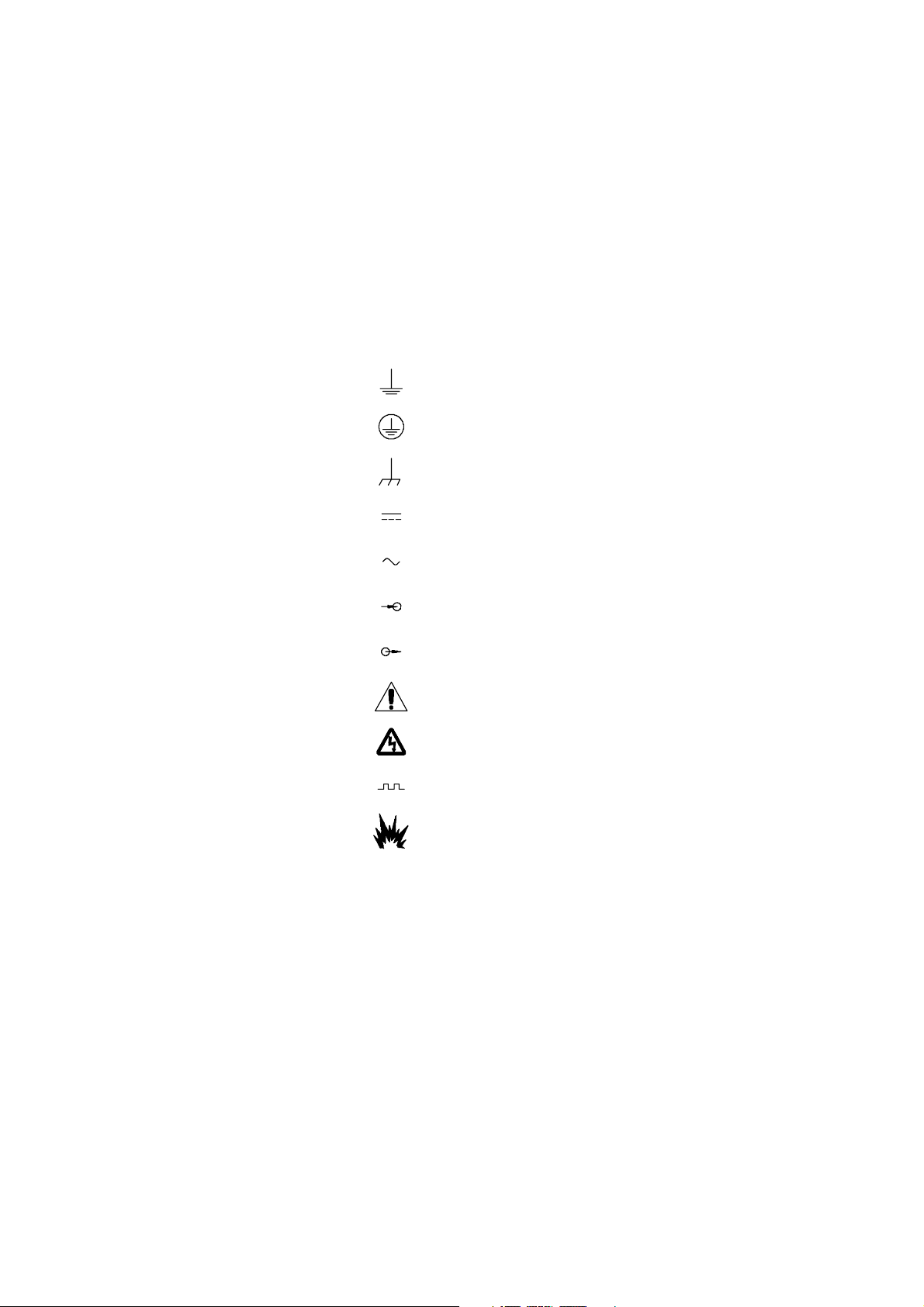
1.2 Symbols Below is a list of symbols pertaining to the manual and the product:
Earth (ground) terminal
Protective conductor terminal
Frame or chassis terminal
Direct current
Alternating current
Input
Output
Alert
Warning, risk of electric shock
Pulse wave
Explosion hazard
2 Series 3000 Installation Manual
Page 9

2 Installing the Model 3300
or 3500 in a Panel
2.1 About this chapter This chapter explains how to mount the Model 3300 application
peripheral or Model 3500 transmitter through a panel cutout.
2.2 Hazardous area installations
2.3 Procedure for mounting in a panel
If you are installing the applications platform or the core processor in a
hazardous area, ensure that your equipment and installation meet the
hazardous area requirements. For more information about hazardous
area classifications, see Appendix A. See Figure 2-4 or Figure 2-5 for
location of the approvals tag on your applications platform.
If you are installing the Model 3300 application peripheral, see the
following section.
Model 3300 installation
The Model 3300 may be installed outdoors, if it is installed in a panel
providing a degree of ingress protection IP 65 according to EN 50529
(IEC 529). The Model 3300 is suitable for installation in Zone 2,
complying with ATEX Directive (94/9/EC) for group II category 3G,
according to CENELEC standard prEN 50021:1998 and marked as EEx
nVL IIC T4.
The procedure for mounting the applications platform in a panel includes
the following steps:
1. Choosing an appropriate location
2. Installing the applications platform in the panel
3. Installing power-supply wiring
4. Installing input and output wiring using the I/O cable or the
screw-type wiring connector
5. If the applications platform is a Model 3500, connecting the Model
3500 to a sensor. To perform Step 5, see Chapter 5.
Installation: Panel-Mount Installation: Field-MountInstallation: Rack-MountBefore You Begin
Installation kit for panel mounting
Series 3000 Installation Manual 3
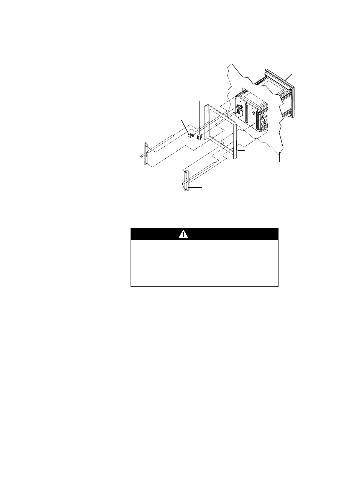
For mounting in a panel, the installation kit includes a bezel, frame, two
mounting brackets with screws, a power-supply wiring connector, and a
retaining clip assembly for power-supply wiring. See Figure 2-1.
• The applications platform fits through a 5 7/16-inch (138 mm) square
cutout in a panel that is 5/64 inch (2 mm) to 1/2 inch (13 mm) thick.
• The panel cutout is the same size as the cutout for a Micro Motion
DRT, FMS-3, DMS, NFC, or NOC peripheral device.
• The bezel provides a NEMA 4X (IP65) watertight seal between the
panel cutout and the applications platform housing.
• The bezel is larger than the bezel on a Micro Motion DRT, FMS-3,
DMS, NFC, or NOC peripheral device.
Page 10
Installing the Model 3300 or 3500 in a Panel continued
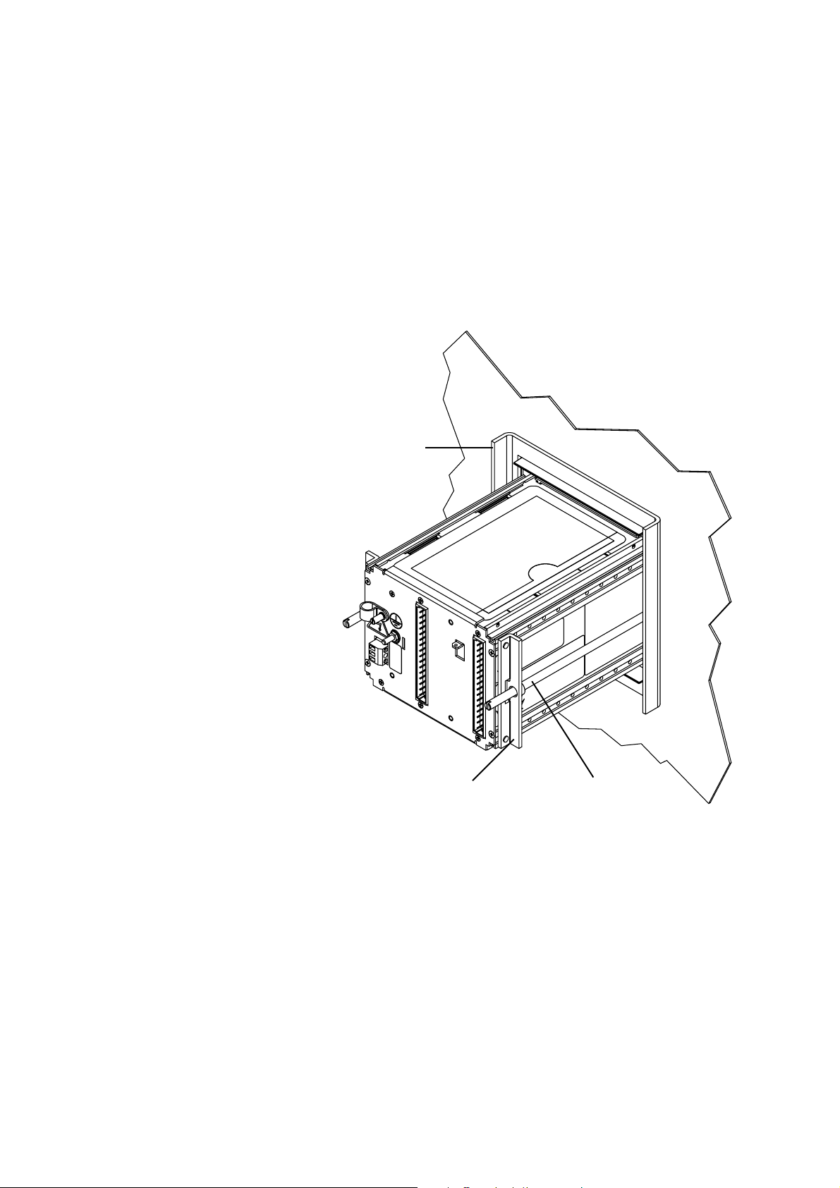
Figure 2-1. Panel-mount installation kit
Retaining-clip
power-supply wiring
Bezel
Power-supply
wiring connector
assembly for
Fram e
Panel thickness:
• 5/64 inch (2 mm) minimum
• 1/2 inch (13 mm) maximum
2 x Mounting bracket with screw
Step 1 Choose an appropriate location
WARNING
Improper installation in a hazardous area could cause
an explosion.
Install the applications platform in an area that is
compatible with the rating on the approvals tag. See
Figure 2-4 and Figure 2-5.
• Install the applications platform where ambient temperature remains
between –4 and 140 °F (–20 and 60 °C).
• Maximum length of cable from a Micro Motion
3500 is 1000 feet (300 meters).
• Maximum length of wiring from the frequency input for a Micro
Motion IFT9701 or RFT9739 transmitter is 500 feet (150 meters).
• If the applications platform has I/O cables, illustrated in Figure 2-2,
see Figure 2-4 for dimensions.
• If the applications platform has screw-type wiring connectors,
illustrated in Figure 2-3, see Figure 2-5 for dimensions.
®
sensor to the Model
4 Series 3000 Installation Manual
Page 11
Installing the Model 3300 or 3500 in a Panel continued
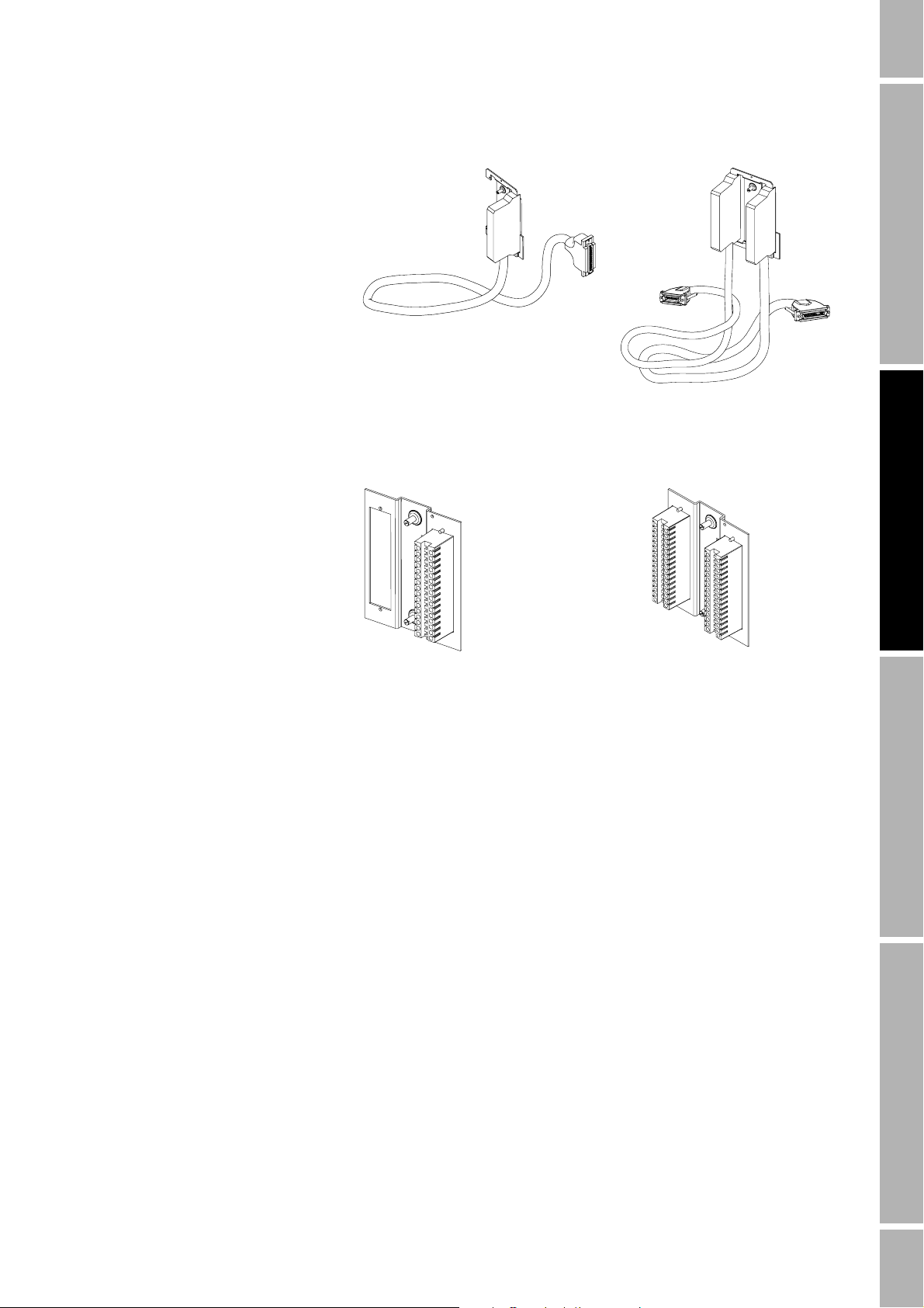
Figure 2-2. I/O cables
Model 3300 Model 3500
Figure 2-3. Screw-type wiring connectors
Model 3300 Model 3500
Series 3000 Installation Manual 5
Installation: Field-MountInstallation: Rack-MountInstallation: Panel-MountBefore You Begin
Page 12
Installing the Model 3300 or 3500 in a Panel continued
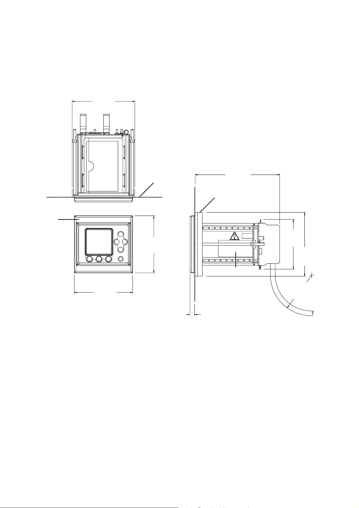
Figure 2-4. Panel-mount dimensions with I/O cables
6 1/2
(165)
Panel
8 3/4
(222)
Fram e
Bezel
6
(152)
6
(152)
5 5/16
(135)
6 11/16
(170)
Approvals tag
Minimum 4 1/4"
(108 mm)
bend radius
1/2
(12)
6 Series 3000 Installation Manual
Page 13
Installing the Model 3300 or 3500 in a Panel continued
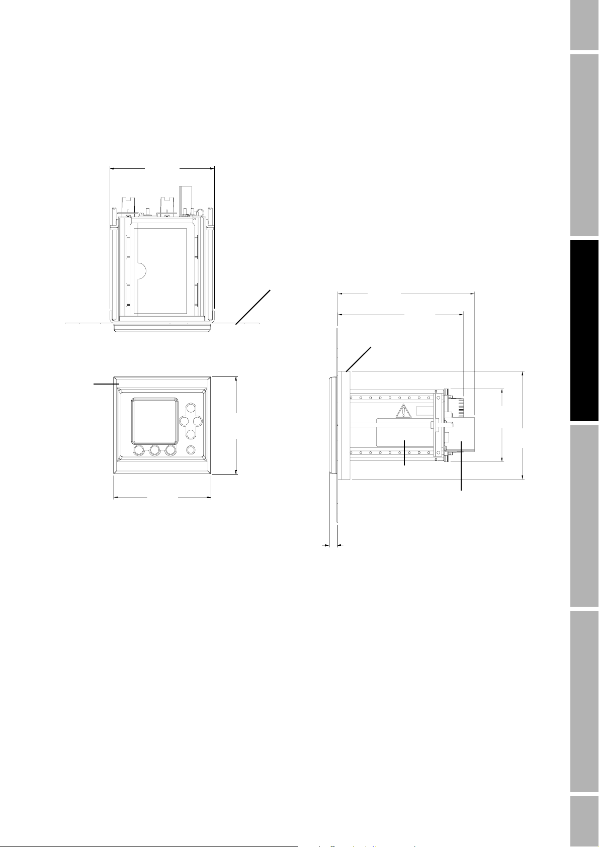
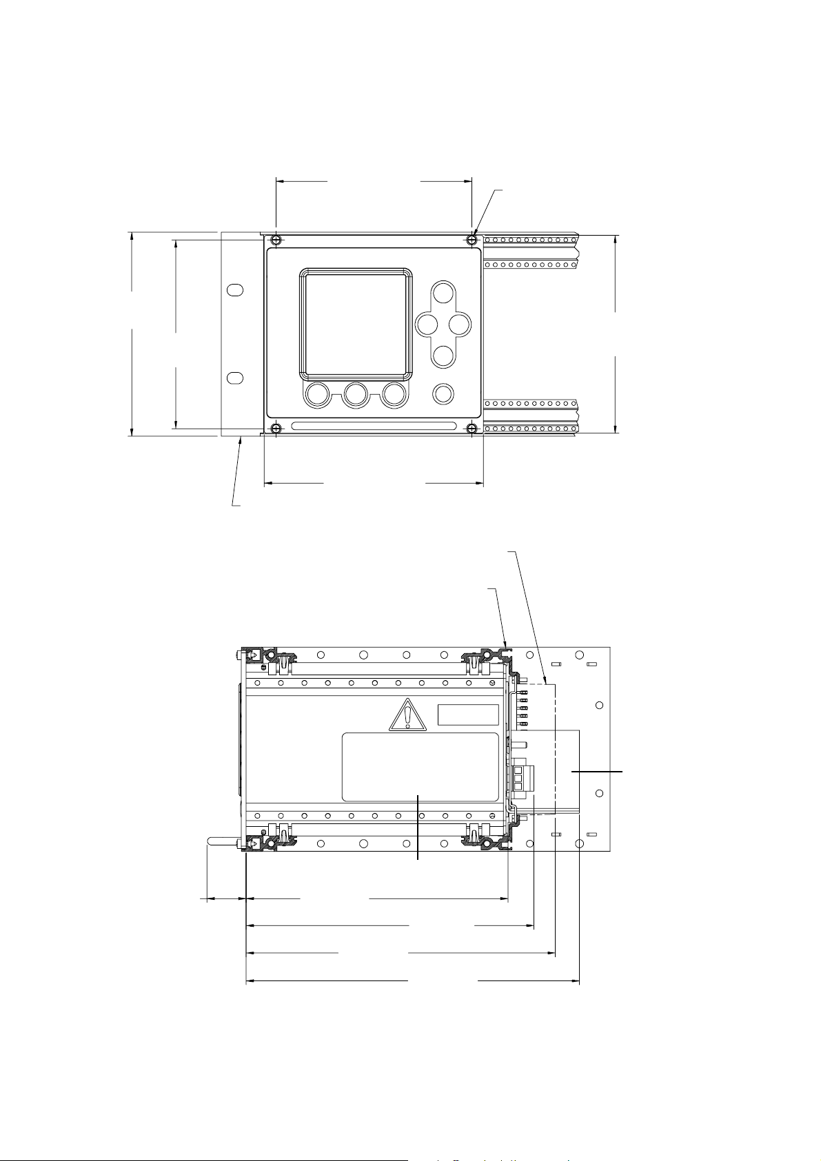
Figure 2-5. Panel-mount dimensions with screw-type connectors
6 1/2
(165)
Bezel
6
(152)
6
(152)
Panel
8 7/16
(214)
7 7/8
(200)
Frame
4 1/2
(114)
6 11/16
(170)
Approvals tag
Intrinsic safety barrier
Model 3500 only
1/2
(12)
Series 3000 Installation Manual 7
Installation: Field-MountInstallation: Rack-MountInstallation: Panel-MountBefore You Begin
Page 14
Installing the Model 3300 or 3500 in a Panel continued
Step 2 Install the applications platform in the panel
Refer to Figure 2-6 and follow these steps:
a. Insert the applications platform through the cutout.
b. Slide the frame over the housing.
c. Insert the posts on the brackets into the rails on the housing.
d. Tighten the screws evenly to 10 to 14 inch-pounds (1,13 to 1,38 Nm)
to ensure a watertight seal between the gasket and the panel.
Figure 2-6. Steps for installation in panel
2. Slide frame
over housing
1. Insert applications platform
through cutout in panel
3. Insert brackets into
upper and lower rails
8 Series 3000 Installation Manual
4. Tighten screws to 10 to 14
in-lb (1,13 to 1,38 Nm)
Page 15
Installing the Model 3300 or 3500 in a Panel continued
Step 3 Install power-supply wiring
Improper wiring installation can cause device failure
or measurement error.
• To avoid device failure or measurement error, do not
install power-supply wiring in the same cable tray or
conduit as input/output wiring.
• Shut off power supply before installing the applications
platform.
• Make sure power-supply voltage matches voltage that is
indicated on power-supply wiring terminals. See
Figure 2-8.
To install power-supply wiring, follow these steps:
a. Plug in the power-supply wiring connector. See Figure 2-7.
b. Connect 18 to 14 AWG (0,75 to 2,5 mm
wiring connector. See Figure 2-8.
• Connect the ground wire to the ground lug for the power supply.
Connect the power-supply ground directly to earth ground.
• Keep all ground leads as short as possible.
• Ground wiring must have less than 1 ohm impedance.
c. Connect wires to the power-supply wiring terminals.
• If the applications platform has a DC power supply, the upper
terminal is negative (–), the lower terminal is positive (+).
• If the applications platform has an AC power supply, the upper
terminal is neutral (N or L1), the lower terminal is line (L or L2).
d. Slide the retaining clip over the wiring, then tighten the screw to hold
the clip in place. See Figure 2-7.
e. A switch may be installed in the power-supply line. For compliance
with low-voltage directive 73/23/EEC, a switch in close proximity to
the applications platform is required.
CAUTION
2
) wiring to the power-supply
Series 3000 Installation Manual 9
Installation: Field-MountInstallation: Rack-MountInstallation: Panel-MountBefore You Begin
Page 16
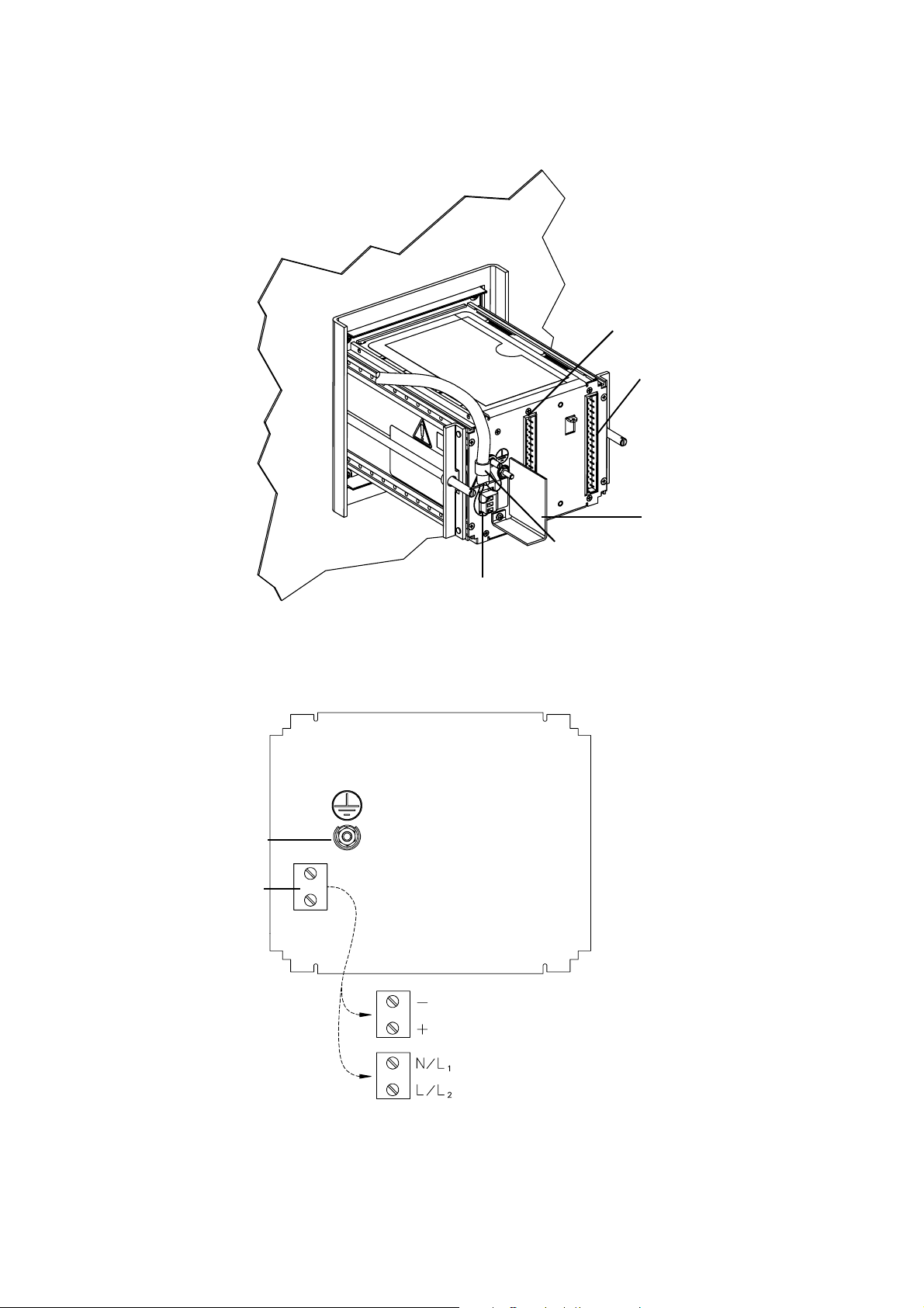
Installing the Model 3300 or 3500 in a Panel continued
Figure 2-7. Wiring connectors and terminals on panel-mount platform
Retaining clip and
screw
Power-supply wiring connector
Sensor wiring
terminal strip
Model 3500 only
Input/output wiring
terminal strip
Intrinsic safety barrier
Model 3500 only
Figure 2-8. Power-supply wiring terminals on panel-mount platform
Ground lug for
power supply
Power-supply
wiring terminals
DC power-supply
terminal designations
AC power-supply
terminal designations
• Connect power-supply ground
directly to earth ground
• Keep all ground leads as short
as possible
• Ground wiring must have less
than 1 ohm impedance
10 Series 3000 Installation Manual
Page 17
Installing the Model 3300 or 3500 in a Panel continued
Step 4 Install input and output wiring
Installation of input and output wiring depends on the type of wiring
connector that is installed.
If the platform has screw-type connectors
a. Plug the bracketed wiring connectors onto the terminal strips on the
back panel of the applications platform.
b. Tighten the captive screws to secure the bracket to the back panel.
c. Connect input and output wiring to the appropriate terminals in the
input/output wiring connector, which is the far right connector.
• Install twisted-pair shielded wiring.
2
• Wire size is 24 to 16 AWG (0,25 to 1,5 mm
).
• Ground the shields at the field device.
• Clip the shields at the end that connects to the applications
platform.
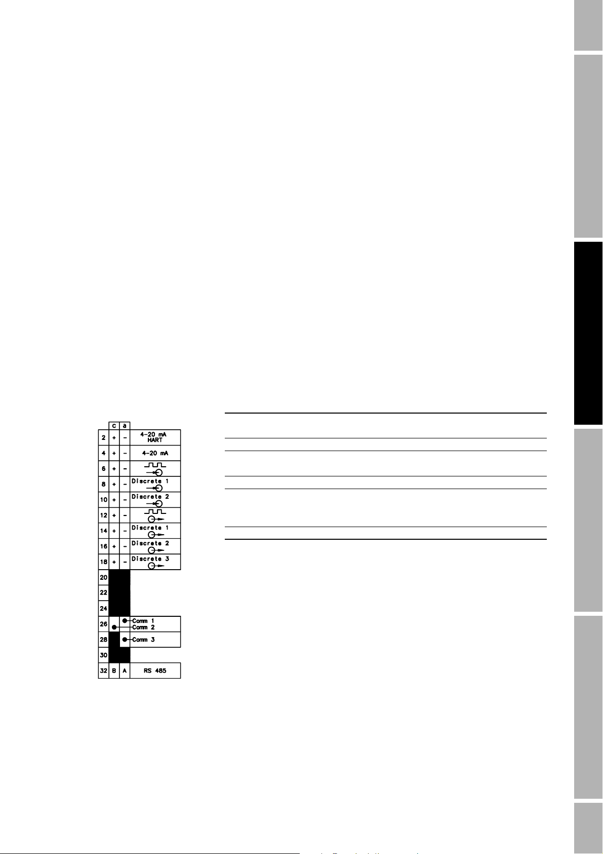
A card that is inserted into the sleeve on the top panel lists input/output
wiring terminal designations.
•See Tabl e 2 -1 and the accompanying figure.
• Input and output assignments depend on the application. For more
information, see the Series 3000 Detailed Setup Manual.
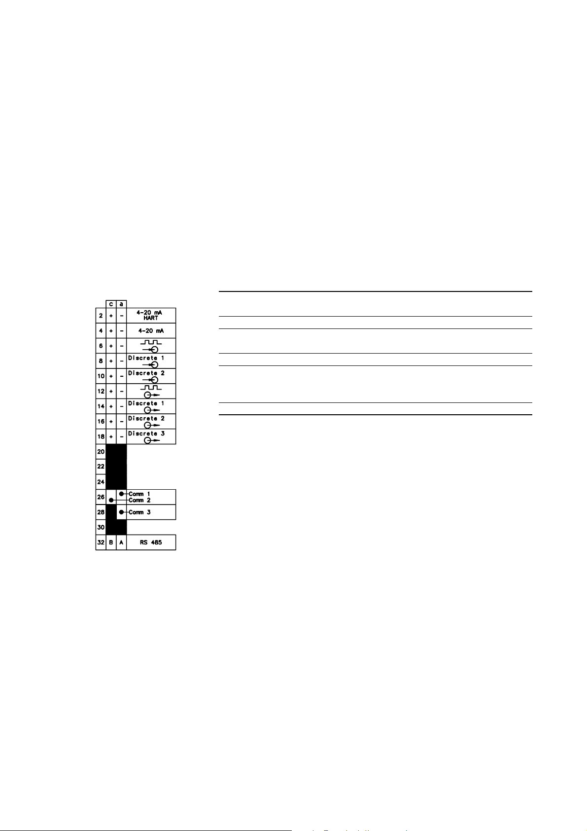
Table 2-1. Input/output wiring terminals on screw-type connector
Terminal number Designation
c 2+ a 2 – Primary 4-20 mA output
c 4 + a 4 – Secondary 4-20 mA output
c 6 + a 6 – Frequency input
c 8 + a 8 – Discrete input 1
c 10 + a 10 – Discrete input 2
c 12 + a 12 – Frequency output
c 14 + a 14 – Discrete output 1
c 16 + a 16 – Discrete output 2
c 18 + a 18 – Discrete output 3
c 32 (B line) a 32 (A line) RS-485 output
Series 3000 Installation Manual 11
Installation: Field-MountInstallation: Rack-MountInstallation: Panel-MountBefore You Begin
Page 18
Installing the Model 3300 or 3500 in a Panel continued
If the platform has I/O cables
a. Plug the bracketed wiring connectors onto the terminal strips on the
back panel of the applications platform. Tighten the captive screws to
secure the bracket to the back panel.
b. Attach the supplied I/O terminal block to a DIN rail. The terminal
block accommodates various rail types. See Figure 2-9.
c. Plug the I/O cable connector onto the terminal block. Tighten the
captive screws to secure the connector to the terminal block.
d. Connect input and output wiring to the appropriate terminals on the
terminal block.
• Install twisted-pair shielded wiring.
• Wire size is 24 to 16 AWG (0,25 to 1,5 mm
• A label that is attached to the terminal block shows terminal
designations for input/output wiring. See Ta ble 2 -2.
• Input and output assignments depend on the application. For
more information, see the Series 3000 Detailed Setup Manual.
e. The terminal block ground is available for continuation of user cable
shielding to I/O cable shielding.
• The cable connector does not connect the I/O cable shielding to
the chassis ground.
•See Figure 2-10.
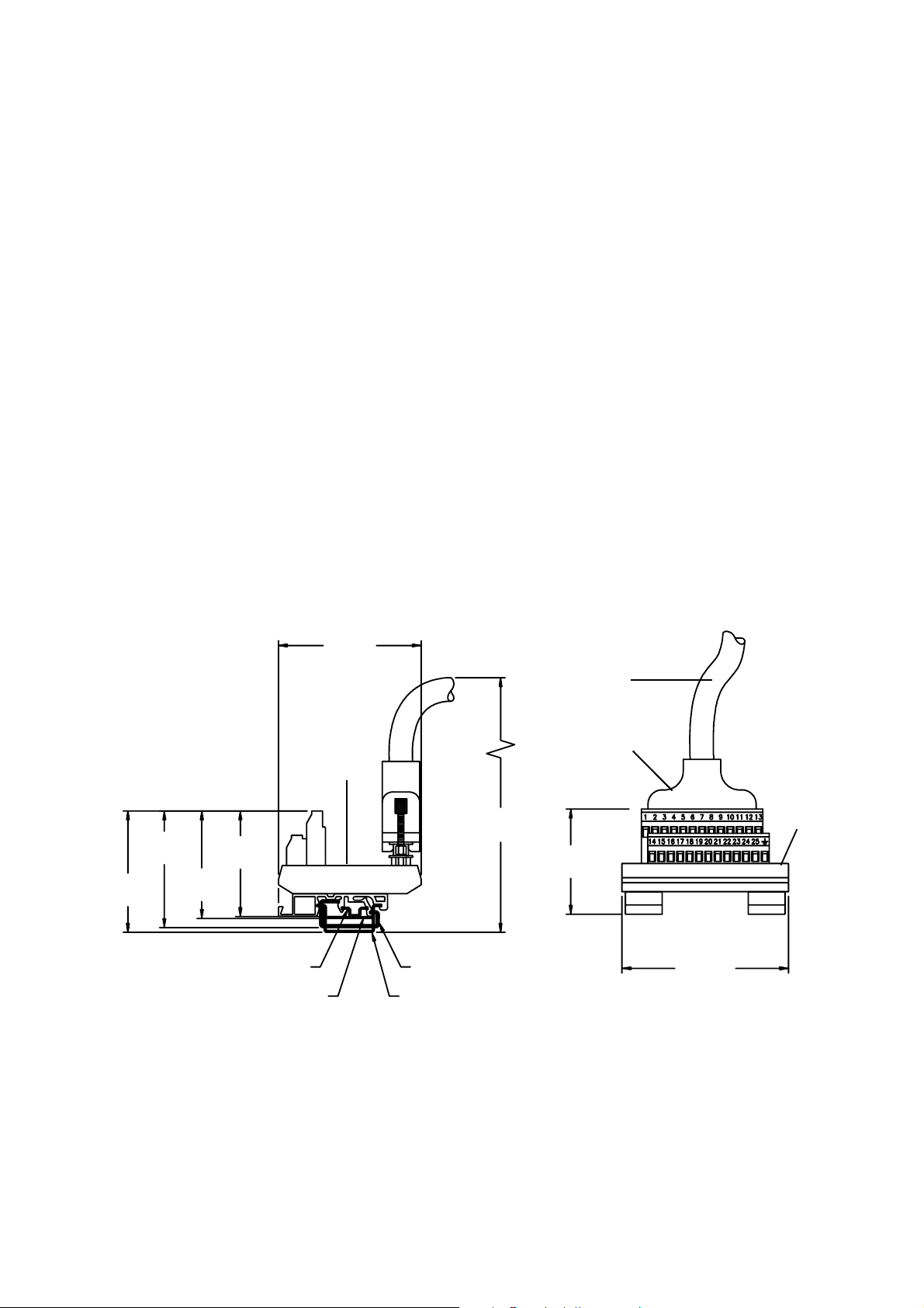
Figure 2-9. Installing input/output terminal block on DIN rail
2
).
2 37/64
(66)
3 3/64
(77)
Label is
mounted
here
2 31/64
(63)
DIN rail type TS 35 x 7.5 DIN rail type TS 35 x 15
2 1/4
(57)
2 19/64
(59)
DIN rail type TS 15 Din rail type TS 32
9
(229)
I/O cable
Connector
Terminal
block
2 15/64
(57)
3 17/32
(90)
12 Series 3000 Installation Manual
Page 19
Installing the Model 3300 or 3500 in a Panel continued
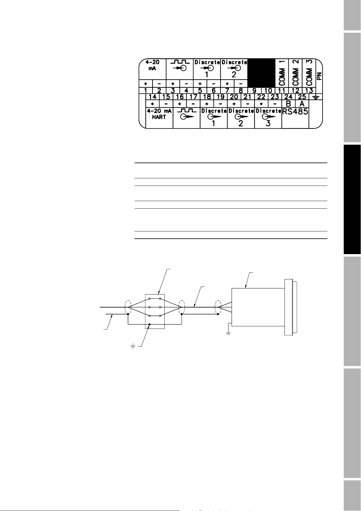
Table 2-2. Input/output wiring terminals on terminal block
Terminal number Designation
1 + 2 – Secondary 4-20 mA output
14 + 15 – Primary 4-20 mA output
3 + 4 – Frequency input
5 + 6 – Discrete input 1
7 + 8 – Discrete input 2
16 + 17 – Frequency output
18 + 19 – Discrete output 1
20 + 21 – Discrete output 2
22 + 23 – Discrete output 3
24 (B line) 25 (A line) RS-485 output
Figure 2-10.Shield wiring for I/O cable to field device
Te r mi n a l b l oc k
Ground shields at
field device only
Terminal marked
Do not ground at this point
Step 5 Connect the Model 3500 to the sensor
To connect the Model 3500 transmitter to a Micro Motion® sensor, see
Chapter 5.
Applications platform
I/O cable
Chassis
ground
Installation: Field-MountInstallation: Rack-MountInstallation: Panel-MountBefore You Begin
Series 3000 Installation Manual 13
Page 20

14 Series 3000 Installation Manual
Page 21

3 Installing the Model 3300
or 3500 in a Subrack
3.1 About this chapter This chapter explains how to mount the Model 3300 application
peripheral or Model 3500 transmitter in a 19-inch (486,2 mm) subrack.
3.2 Hazardous area installations
3.3 Procedure for mounting in subrack
If you are installing the applications platform or the core processor in a
hazardous area, ensure that your equipment and installation meet the
hazardous area requirements. For more information about hazardous
area classifications, see Appendix A. See Figure 3-1 for location of the
approvals tag on your applications platform. If you are installing the
Model 3300 application peripheral, see below.
Model 3300 installation
The Model 3300 should be installed in a rack providing a degree of
ingress protection IP 4X according to EN 50529 (IEC 529). The Model
3300 is suitable for installation in Zone 2, complying with ATEX Directive
(94/9/EC) for group II category 3G, according to CENELEC standard
prEN 50021:1998 and marked as EEx nVL IIC T4.
The procedure for mounting the applications platform in a subrack
includes the following steps:
1. Choosing an appropriate location for the installation
2. Installing guide rails and wiring connectors
3. Installing the applications platform in the subrack
4. Connecting power-supply wiring
5. Connecting input/output wiring
6. If the applications platform is a Model 3500, connecting the Model
3500 to a sensor. To perform Step 6, see Chapter 5.
Installation: Panel-Mount Installation: Field-MountInstallation: Rack-MountBefore You Begin
Installation kit for rack mounting
Series 3000 Installation Manual 15
Model 3300 installation kit
For mounting in a subrack, the Model 3300 installation kit includes the
following parts (see Figure 3-3):
• One DIN standard 41612, Type D connector for input/output wiring,
with solder tails or screw terminals
• One plug-in connector for power-supply wiring
• Four slotted cheese-head machine screws, size M2.5x8, for securing
wiring connectors to the subrack
Model 3500 installation kit
For mounting in a subrack, the Model 3500 installation kit includes the
following parts (see Figure 3-3):
• One DIN standard 41612, Type D connector for input/output wiring,
with solder tails or screw terminals
• One DIN standard 41612, keyed Type D connector for sensor wiring,
with solder tails or screw terminals
• One plug-in connector for power-supply wiring
• Six slotted cheese-head machine screws, size M2.5x8, for securing
wiring connectors to the subrack
Page 22
Installing the Model 3300 or 3500 in a Subrack continued
Figure 3-1. Dimensions for mounting in subrack
25 HP (25 TE)
3 U
(3 HE)
4 13/16
(122,5)
5.6
(142,2)
28 HP (28 TE)
19-inch (486,2 mm) subrack conforms to DIN 41494, Part 5, and IEC 297-3
Not included with applications platform
1 U = 1 HE = 1.750 inches (44,45 mm)
1 HP = 1 TE = 0.200 inch (5,08 mm)
4 x M2.5x11
5 1/16
(128,52)
1
(25,4)
Optional screw terminal
Rear rail for mounting connectors
that conform to DIN 41612 and IEC 603-2
Not included with applications platform
Intrinsic safety barrier
Model 3500 only
Approvals tag
6 11/16
(169,93)
7 11/32
(186,7)
7 29/32
(200,6)
8 33/64
(216,23)
16 Series 3000 Installation Manual
Page 23
Installing the Model 3300 or 3500 in a Subrack continued
Step 1 Locate and orient the applications platform
Improper installation in a hazardous area could cause
an explosion.
Install the applications platform in an area that is
compatible with the rating on the approvals tag. See
Figure 3-1.
WARNING
Dimensions
The applications platform conforms to DIN standard 41494, Part 5
(IEC 297-3) for 19-inch (486,2 mm) racks.
• Up to three applications platform enclosures fit into one subrack. See
Figure 3-2.
• Height is 128 mm (3 U or 3 HE).
• Width is 142 mm (28 HP or 28 TE).
• Depth is 160 mm.
Location guidelines • Locate the applications platform where ambient temperature remains
between –4 and 140 °F (–20 and 60 °C).
• Maximum length of cable from a Micro Motion
3500 is 1000 feet (300 meters).
• Maximum length of wiring from the frequency input for a Micro
Motion IFT9701 or RFT9739 transmitter is 500 feet (150 meters).
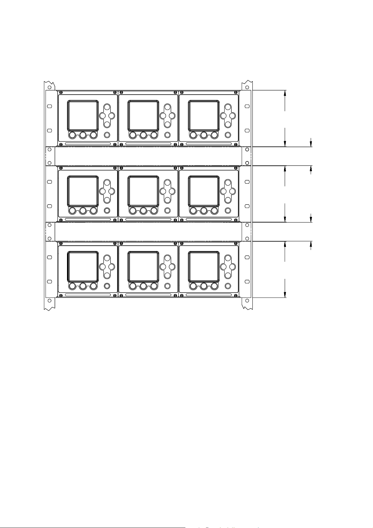
• To ensure proper ventilation if multiple application platforms are
installed, provide at least 1 U (1 HE) of vertical space between
subracks, as shown in Figure 3-2.
®
sensor to the Model
Installation: Panel-Mount Installation: Field-MountInstallation: Rack-MountBefore You Begin
Series 3000 Installation Manual 17
Page 24
Installing the Model 3300 or 3500 in a Subrack continued
Figure 3-2. Space requirements for proper ventilation
1 U = 1 HE = 1.750 inches (44,45 mm)
3 U (3 HE)
1 U (1 HE)
3 U (3 HE)
3 U (3 HE)
1 U (1 HE)
18 Series 3000 Installation Manual
Page 25

Installing the Model 3300 or 3500 in a Subrack continued
Step 2 Install guide rails and wiring connectors
Guide rails
Positions of guide rails and wiring connectors are indicated in
Figure 3-3. Centers of guide rails should be 27 HP (27 TE) apart, for
example, at 1 HP (TE) and 28 HP (TE).
Wiring connectors • Use the supplied M2.5x8 screws to install the wiring connectors onto
the back of the subrack.
• Install screws and connectors from the front of the subrack.
Model 3300 wiring connectors
The Model 3300 comes with a solder tail or screw-type connector for
input/output wiring and a plug-in connector for power-supply wiring.
Model 3500 wiring connectors
The Model 3500 comes with a solder tail or screw-type connector for
input/output wiring, a keyed solder tail or screw-type connector for
sensor wiring, and a plug-in connector for power-supply wiring.
Using the centers of the guide rails as reference points and referring to
Figure 3-3, install the wiring connectors in the following positions on the
back of the subrack:
• Install the input/output wiring connector at 4 HP (4 TE) from the
neighboring unit or from the edge of the subrack.
• If the applications platform is a Model 3500, install the keyed sensor
wiring connector at 16 HP (16 TE) from the neighboring unit or from
the edge of the subrack.
• Install the power-supply wiring connector at 25 HP (25 TE) from the
neighboring unit or from the edge of the subrack.
Installation: Panel-Mount Installation: Field-MountInstallation: Rack-MountBefore You Begin
Series 3000 Installation Manual 19
Page 26

Installing the Model 3300 or 3500 in a Subrack continued
Step 3 Install the applications platform in the subrack
After installing guide rails and wiring connectors as instructed in Step 2,
follow these steps to install the applications platform in the subrack:
a. Align the applications platform with the guide rails.
b. Slide the applications platform into the subrack. Make sure the pins
on the back panel make contact with the wiring connectors.
c. Tighten the supplied captive screws to secure the front panel of the
applications platform to the guide rails.
Figure 3-3. Positions of guide rails and wiring connectors
Guide rail centers should be 27 HP (27 TE) apart;
for example, 1 HP (1 TE) and 28 HP (28 TE)
Install screws and connectors from front of subrack
• Model 3300 has four M2.5x8 screws and two connectors
• Model 3500 has six M2.5x8 screws and three connectors
Front
Back
Keys on sensor
wiring connector
Model 3500 only
M2.5x8
Power-supply wiring connector is
25 HP (25 TE) from neighboring
unit or from edge of subrack
Model 3500 only
Keyed sensor wiring connector is
16 HP (16 TE) from neighboring unit
or from edge of subrack
Input/output wiring connector is 4 HP (4 TE) from
neighboring unit or from edge of subrack
20 Series 3000 Installation Manual
Page 27

Installing the Model 3300 or 3500 in a Subrack continued
Step 4 Connect power-supply wiring
Improper wiring installation can cause device failure
or measurement error.
• To avoid device failure or measurement error, do not
install power-supply wiring in the same cable tray or
conduit as input/output wiring.
• Shut off power supply before installing the applications
platform.
• Make sure power-supply voltage matches voltage that is
indicated on power-supply wiring terminals. See
Figure 3-4.
CAUTION
Installation: Panel-Mount Installation: Field-MountInstallation: Rack-MountBefore You Begin
Referring to Figure 3-4, follow these steps to connect 18 to 14 AWG
2
(0,75 to 2,5 mm
) wiring to the power-supply wiring connector.
a. Connect the ground wire to the middle terminal.
b. Connect the power-supply ground directly to earth ground.
• Keep all ground leads as short as possible.
• Ground wiring must have less than 1 ohm impedance.
c. Connect wires to the upper and lower terminals.
• If the applications platform has a DC power supply, the upper
terminal is negative (–), the lower terminal is positive (+).
• If the applications platform has an AC power supply, the upper
terminal is neutral (N or L1), the lower terminal is line (L or L2).
d. A switch may be installed in the power-supply line. For compliance
with low-voltage directive 73/23/EEC, a switch in close proximity to
the subrack is required.
Figure 3-4. Power-supply wiring terminals on rack-mount platform
Power-supply
wiring terminals
Terminal designations
for DC power
Terminal designations
for AC power
Series 3000 Installation Manual 21
Page 28
Installing the Model 3300 or 3500 in a Subrack continued
Step 5 Connect input and output wiring
Connect input and output wiring to the appropriate terminals on the
input/output wiring connector, which is the far right connector.
• Install twisted-pair shielded wiring, 24 to 16 AWG (0,25 to 1,5 mm
• Ground the shields at the field device.
• Clip the shields at the end that connects to the applications platform.
A card that is inserted into the sleeve on the top panel lists input/output
wiring terminal designations.
•See Tabl e 3 -1 and the accompanying figure.
• Input and output assignments depend on the application. For more
information, see the Series 3000 Detailed Setup Manual.
Table 3-1. Input/output wiring terminals on rack-mount platform
Terminal number Designation
c 2+ a 2 – Primary 4-20 mA output
c 4 + a 4 – Secondary 4-20 mA output
c 6 + a 6 – Frequency input
c 8 + a 8 – Discrete input 1
c 10 + a 10 – Discrete input 2
c 12 + a 12 – Frequency output
c 14 + a 14 – Discrete output 1
c 16 + a 16 – Discrete output 2
c 18 + a 18 – Discrete output 3
c 32 (B line) a 32 (A line) RS-485 output
2
).
Step 6 Connect the Model 3500 to the sensor
To connect the Model 3500 transmitter to a Micro Motion® sensor, see
Chapter 5.
22 Series 3000 Installation Manual
Page 29
4 Installing the
Model 3350 or 3700
4.1 About this chapter This chapter explains how to install the Model 3350 application
peripheral or Model 3700 transmitter. The Model 3350 or 3700 can be
installed on an instrument pole or a flat surface.
4.2 Hazardous area classifications
If you are installing the applications platform or the core processor in a
hazardous area, ensure that your equipment and installation meet the
hazardous area requirements. For more information about hazardous
area classifications, see Appendix A. See Figure 4-2 for location of the
approvals tag on your applications platform.
WARNING
Explosion Hazard.
Do not open wiring compartments when an explosive
gas atmosphere is present.
Figure 4-4 identifies the compartments.
WARNING
Using a dry cloth to clean the display cover can cause
static discharge, which could result in an explosion in
an explosive atmosphere.
To prevent an explosion, use a clean, damp cloth to clean
the display cover in an explosive atmosphere.
Installation: Panel-Mount Installation: Field-MountInstallation: Rack-MountBefore You Begin
4.3 Procedure for field mounting
Installation kit for field
The procedure for field mounting includes the following steps:
1. Choosing an appropriate location for the installation
2. Orienting the display cover for optimal viewing
3. Mounting the applications platform on an instrument pole or flat
surface
4. Connecting power-supply wiring
5. Connecting input/output wiring
6. If the applications platform is a Model 3700, connecting the Model
3700 to a sensor. To perform Step 6, see Chapter 5.
The field-mount installation kit includes the parts shown in Figure 4-1.
mounting
Series 3000 Installation Manual 23
Page 30
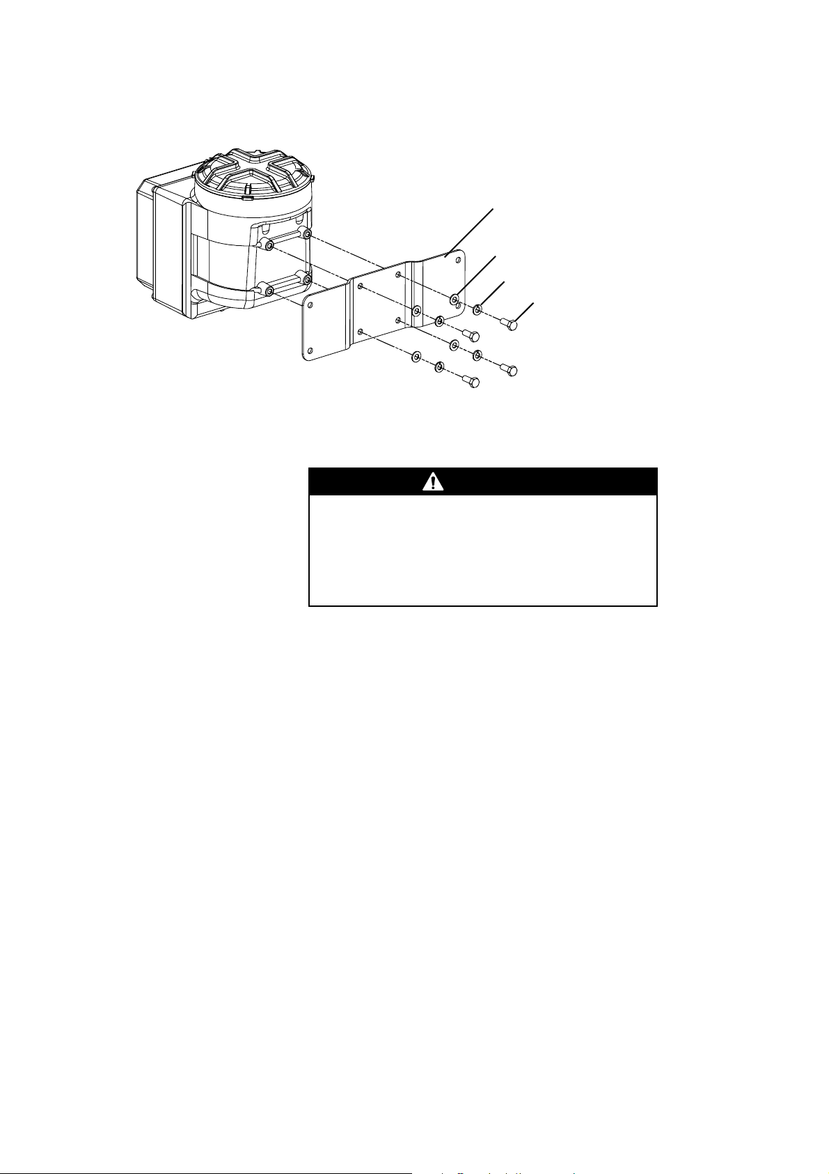
Installing the Model 3350 or 3700 continued
Figure 4-1. Parts in field-mount installation kit
Step 1 Locate and orient the applications platform
Mounting bracket
4 x Flat washer
4 x Lock washer
4 x M8x16
Using a 13 mm hex wrench,
install to 12 ft-lb (16 Nm)
WARNING
Improper installation in a hazardous area could cause
an explosion.
Install the applications platform in an area that is
compatible with the rating on the approvals tag. See
Figure 4-2.
Proximity to other devices
• Maximum length of cable from a Micro Motion® sensor to the Model
3700 is 1000 feet (300 meters).
• Maximum length of wiring from the frequency input for a Micro
Motion IFT9701 or RFT9739 transmitter is 500 feet (150 meters).
Visibility of tags To ensure personal and system safety, all tags attached to the housing
must remain visible. Clean them as often as necessary. Replace tags
that are damaged, missing, or worn.
Temperature, humidity, and vibration
Install the applications platform according to specified limits:
• Ambient temperature: –4 to 140°F (–20 to 60°C)
• Humidity: SAMA PMC 31.3, Section 5.2, Environmental
NEMA 4X (IP65)
• Vibration: Per IEC 68-2-6 at 1.0 g, 15 to 2000 Hz, 50 sweep cycles
Orientation Orient the applications platform so wiring compartments and conduit
openings are easily accessible. Conduit openings can be on the right,
left, bottom, or top of the housing, regardless of the positions of the
display cover or wiring compartments. See Figure 4-2 and Figure 4-3.
• To orient the applications platform on the mounting bracket, use the
four supplied mounting bolt assemblies.
• Install the bolt assemblies to 12 ft-lb (16 Nm) of torque.
24 Series 3000 Installation Manual
Page 31

Installing the Model 3350 or 3700 continued
Figure 4-2. Approvals tag and wiring terminals
Mounting bracket can
be rotated 90°
If CENELEC approval is required:
• Remove thread protectors from
conduit openings
• Install factory-supplied cable
glands or user-supplied EExe
cable entry devices in conduit
openings that are in use
• Install EExe plugs in conduit
openings that are not in use
• Mounting with conduit openings on left
• For other possible orientations, see
Figure 4-3
Approvals tag
Intrinsically safe wiring
terminals
(blue terminal block)
Non-intrinsically safe
wiring terminals
(gray terminal block)
Display cover can be
rotated 90 ° or 180°
(see Step 2)
Figure 4-3. Typical orientations
Mounting with conduit openings on right Mounting with conduit openings
Mounting bracket
can be rotated 90 °
pointing downward
Installation: Panel-Mount Installation: Field-MountInstallation: Rack-MountBefore You Begin
Lockout device
Platform approved for ATEX Zone 1
Conduit openings for
non-intrinsically safe wiring
Conduit openings for
intrinsically safe wiring
Mounting bracket
can be rotated 90°
The circuit board compartment has a lockout device, shown in
Figure 4-4. The lockout device must be loosened and rotated before the
compartment cover can be opened.
If the applications platform carries a ATEX Zone 1 approval, wiring
terminals are rated as shown in Figure 4-4.
• Remove thread protectors from conduit openings.
• Install factory-supplied cable glands or user-supplied EExe cable
entry devices in conduit openings that are in use.
• Install EExe plugs in conduit openings that are not in use.
The wiring compartments are rated EEx e. They must remain closed
when power is on.
• The wiring terminals on the blue terminal block are rated EEx i
(intrinsically safe).
• The wiring terminals on the gray terminal block are rated EEx e
(increased safety).
Series 3000 Installation Manual 25
Page 32

Installing the Model 3350 or 3700 continued
Figure 4-4. Wiring terminals and lockout device
Circuit board
compartment
Rated EEx d
Lockout device
Loosen and rotate before opening
circuit board compar tment
Intrinsically safe
wiring terminals
(blue terminal block)
Rated EEx i
Wiring compartment
Should remain closed
while power is on
Label for intrinsically safe
wiring terminals
Increased safety
wiring terminals
(gray terminal block)
Rated EEx e
Power-supply ground
Label for increased safety wiring
terminals (See Figure 4-8)
26 Series 3000 Installation Manual
Page 33

Installing the Model 3350 or 3700 continued
Figure 4-5. Model 3350 or 3700 dimensions
4 x 5/16-inch
(9 mm)
diameter
2 13/16
(71)
Mounting bracket
can be rotated 90 °
12
(305)
11
(279)
9 3/16
(234)
Installation: Panel-Mount Installation: Field-MountInstallation: Rack-MountBefore You Begin
4
(102)
Display cover can be
rotated 90° or 180°
6 1/8
(158)
3 5/8
(92)
6
(152)
5 1/16-inch (129 mm)
clearance for removal
of circuit boards
Approvals tag
11 5/16
(288)
8 11/16
(221)
15 1/2
(394)
Series 3000 Installation Manual 27
Page 34

Installing the Model 3350 or 3700 continued
Step 2 Orient the display cover
a. Use a flat-head screwdriver to loosen the captive screws that secure
b. Use a flat-head screwdriver to loosen the captive screws that secure
the display cover to the housing.
the back cover to the display cover. Take note of which screw
attaches the ground wire to the back cover.
c. Pull up on the pressure relief valve while removing the back cover.
d. Rotate the display cover to any desired position.
e. Without touching the circuit board, tuck the wiring out of the way of
the circuit board to prevent the wiring from crimping, then reinstall the
back cover.
28 Series 3000 Installation Manual
Page 35

Installing the Model 3350 or 3700 continued
f. Pull up on the pressure relief valve while pressing the back cover into
g. Tuck the wiring out of the way of the connectors to prevent the wiring
place. Be sure to attach the ground wire to the back cover using the
correct screw. Attaching the ground wire to the wrong screw may
result in crimping of the ground wire.
from crimping, then reinstall the display cover.
Installation: Panel-Mount Installation: Field-MountInstallation: Rack-MountBefore You Begin
Guidelines for flat-surface mounting
Guidelines for pole mounting
Step 3 Mount the Model 3350 or 3700
• Use four 5/16-inch (M8) lag bolts (not included), suitable for the
environment.
• Do not secure bolts to separate beams, girders, wall studs, etc.,
which can move independently.
• For more information, see Figure 4-6.
• Use two 5/16-inch U bolts for 2-inch pipe, and four 5/16-inch nuts
(not included), suitable for the environment.
• For more information, see Figure 4-7.
Figure 4-6. Mounting to a wall or other surface
4 x 5/16-inch (M8) bolt (user-supplied)
• Mount all 4 bolts to the same surface
• If mounting surface is not flat, use
washers to shim the bracket
Series 3000 Installation Manual 29
Page 36

Installing the Model 3350 or 3700 continued
Figure 4-7. Mounting to an instrument pole
Step 4 Connect power-supply wiring
4 x 5/16-inch nut
(user-supplied)
2 x 5/16-inch U bolt for
2-inch pipe (user-supplied)
CAUTION
Improper wiring installation can cause device failure
or measurement error.
• To avoid device failure or measurement error, do not
install power-supply wiring in the same cable tray or
conduit as input/output wiring.
• Shut off power supply before installing the applications
platform.
• Make sure power-supply voltage matches voltage that is
indicated on power-supply wiring terminals. See
Figure 4-8.
Follow these steps to connect 18 to 12 AWG (0,75 to 4,0 mm2) wiring to
the power-supply wiring terminals.
a. Using a flat-head screwdriver, loosen the captive screws that secure
the display cover to the housing.
b. Connect the ground wire to green screw.
c. Connect the green screw directly to earth ground.
• Keep all ground leads as short as possible.
• Ground wiring must have less than 1 ohm impedance.
d. Connect wires to terminals 9 and 10 on the gray terminal strip. See
Figure 4-8.
• If the Model 3700 has a DC power supply, terminal 9 is
positive (+), terminal 10 is negative (–).
• If the Model 3700 has an AC power supply, terminal 9 is line (L or
L2), terminal 10 is neutral (N or L1).
e. A switch may be installed in the power-supply line. For compliance
with low-voltage directive 73/23/EEC, a switch in close proximity to
the applications platform is required.
30 Series 3000 Installation Manual
Page 37

Installing the Model 3350 or 3700 continued
Figure 4-8. Field-mount input/output wiring terminals
DC power supplyAC power supply
Installation: Panel-Mount Installation: Field-MountInstallation: Rack-MountBefore You Begin
Terminal 9: line (L or L2)
Terminal 10: neutral (N or L1)
Terminal 9: positive
Terminal 10: negative
Step 5 Connect input and output wiring
Follow these steps to connect twisted-pair, shielded wiring, 22 to
16 AWG (0,34 to 1,5 mm
a. Using a flat-head screwdriver, loosen the captive screws that secure
the display cover to the housing.
b. Connect input/output wiring to the gray terminal strip.
• Ground the shields at the field device.
• Clip the shields at the end that connects to the applications
platform.
• If more than two wires must be connected to a single terminal, use
a butt splice or spade lug to connect the wires.
A label that is attached to the back of the display cover shows terminal
designations for input/output wiring.
•See Figure 4-8 and Table 4-1.
• Input and output assignments depend on the application. For more
information, see the Series 3000 Detailed Setup Manual.
2
), to the input/output wiring terminals.
Series 3000 Installation Manual 31
Page 38

Installing the Model 3350 or 3700 continued
Table 4-1. Field-mount input/output wiring terminals
Terminal number Designation
1 – 2 + Primary 4-20 mA output
3 – 4 + Secondary 4-20 mA output
5 – 6 + Frequency input
5 – 7 + Discrete input 1
5 – 8 + Discrete input 2
11 (B line) 12 (A line) RS-485 output
20 – 16 + Discrete output 3
20 – 17 + Discrete output 2
20 – 18 + Discrete output 1
20 – 19 + Frequency output
Step 6 Connect the Model 3700 to the sensor
To connect the Model 3700 transmitter to a Micro Motion® sensor, see
Chapter 5.
32 Series 3000 Installation Manual
Page 39

5 Connecting the
Transmitter to a Sensor
5.1 About this chapter This chapter explains how to connect the Model 3500 or 3700
®
transmitter to a Micro Motion ELITE
DL, or Model DT sensor. For other sensors, see the sensor installation
manual.
• Use Micro Motion 9-wire cable to connect the transmitter to the
sensor.
• Total length of cable from sensor to transmitter must not exceed
1000 feet (300 meters).
, T-Series, BASIS®, Model D, Model
WARNING
Failure to maintain intrinsic safety could result in an
explosion.
To keep sensor wiring intrinsically safe:
• Keep intrinsically safe sensor wiring separated from
power-supply and output wiring.
• Do not install power cable in the same conduit or cable
tray as flowmeter cable.
• Use this document with Micro Motion ATEX, UL, or CSA
installation instructions that are shipped with the sensor.
Installation: Relays StartupPrinter SetupSensor Wiring
CAUTION
Improper installation of cable, cable gland, or conduit
could cause inaccurate measurements or flowmeter
failure.
To ensure 360° termination of shielding for flowmeter
wiring, install the factory-supplied cable gland or
user-supplied sealed metallic conduit to the conduit
opening on the sensor junction box.
Series 3000 Installation Manual 33
Page 40

Connecting the Transmitter to a Sensor continued
5.2 Cable types Micro Motion supplies 9-wire jacketed, shielded, or armored cable.
• Jacketed cable is CE-compliant when it is installed inside
user-supplied sealed metallic conduit that provides 360 ° termination
shielding and continuous coverage for the enclosed cable.
• Shielded and armored cable are CE-compliant when the cable is
installed with the factory-supplied cable glands.
• Shielded and armored cable are acceptable for cable tray
installation.
®
• Each cable type is available with a PVC or Teflon
FEP jacket. For
temperature ranges of cable jacket materials, see Tabl e 5-1 .
• Use shielded or armored cable with Micro Motion T-Series sensors.
CAUTION
Failure to use shielded or armored cable with Micro
Motion T-Series sensors could cause inaccurate
measurements.
Install Micro Motion shielded or armored cable with Micro
Motion T-Series sensors.
5.3 Cable and conduit preparation
Guidelines for cable gland 1. Prepare cable ends and assemble the supplied cable gland
Guidelines for conduit If sealed metallic conduit is installed, it must provide 360 ° termination
Prepare cable and conduit according to the cable preparation
instructions that are shipped with the sensor.
according to the instructions that are enclosed with the cable
preparation kit.
2. Connect the ¾-inch NPT male cable gland to the ¾-inch NPT female
conduit opening on the sensor junction box.
shielding for the enclosed flowmeter cable.
1. Install a drip leg in conduit to prevent liquids from entering the
junction box.
2. Connect the sealed end of the conduit to the ¾-inch NPT female
conduit opening on the sensor junction box.
34 Series 3000 Installation Manual
Page 41

Connecting the Transmitter to a Sensor continued
Figure 5-1. Jacketed cable
Jacket
material
PVC .415 (10) 3 1/8 (80) 6 1/4 (159)
Teflon FEP .340 (9) 2 5/8 (67) 5 1/8 (131)
Figure 5-2. Shielded cable
Jacket
Drain wire (4)
Filler (5)
Minimum bend radii
Outside diameter Static (no load) Dynamic load
inches (mm) inches (mm) inches (mm)
Outer jacket
Installation: Relays StartupPrinter SetupSensor Wiring
Tin-plated copper
braided shield
Foil shield
Inner
jacket
Filler
(5)
Note for Figure 5-2
Drain wire (4)
You must install shielded or armored cable with Micro Motion T-Series
sensors.
Minimum bend radii
Jacket
material
PVC .560 (14) 4 1/4 (108) 8 1/2 (216)
Teflon FEP .425 (11) 3 1/4 (83) 6 3/8 (162)
Outside diameter Static (no load) Dynamic load
inches (mm) inches (mm) inches (mm)
Series 3000 Installation Manual 35
Page 42

Connecting the Transmitter to a Sensor continued
Figure 5-3. Armored cable
Filler
(5)
Note for Figure 5-3
You must install shielded or armored cable with Micro Motion T-Series
sensors.
Jacket
material
PVC .560 (14) 4 1/4 (108) 8 1/2 (216)
Teflon FEP .425 (11) 3 1/4 (83) 6 3/8 (162)
Outer jacket
Stainless steel
braided shield
Foil shield
Inner
jacket
Drain wire (4)
Minimum bend radii
Outside diameter Static (no load) Dynamic load
inches (mm) inches (mm) inches (mm)
Table 5-1. Temperature ranges for cable jacket material
Cable jacket material
PVC –40 °F (–40°C) 221 °F (105°C)
Teflon FEP –76°F (–60°C) 302°F (150 °C)
Low operating
temperature limit
High operating
temperature limit
Table 5-2. Requirements for CE Mark in Europe,
recommendations for elsewhere
Installation requirements
Conduit is used X
Conduit is not used X
Conduit is not used and
mechanical protection is required X
Micro Motion T-Series sensor is
being installed
Jacketed
cable
Shielded
cable
XX
Armored
cable
36 Series 3000 Installation Manual
Page 43

Connecting the Transmitter to a Sensor continued
5.4 Wiring connections to sensor
1. Insert the ends of the individual wires into the terminals inside the
sensor junction box. No bare wires should remain exposed.
2. Match the wire colors of the cable with the wire colors at the sensor
wiring terminal as described in Table 5 -3.
3. If possible, position the junction box so the conduit entrance points
downward to prevent moisture from entering.
CAUTION
Failure to seal sensor junction box or transmitter
housing could cause a short circuit, which would
result in measurement error or flowmeter failure.
To avoid risk of condensation or excessive moisture
entering the junction box or transmitter housing:
• Seal all conduit openings.
• Install drip legs in cable or conduit.
• Fully tighten sensor junction box and transmitter housing
covers.
Table 5-3. Sensor terminal designations
Terminal
number
1
2
3
4
5
6
7
8
9
Wire
color Function
Brown
Red
Orange
Ye l l o w
Green
Blue
Violet
Gray
White
Drive +
Drive –
Temperature –
Temperature lead length compensator
Left pickoff +
Right pickoff +
Temperature +
Right pickoff –
Left pickoff –
Installation: Relays StartupPrinter SetupSensor Wiring
5.5 Wiring connections to transmitter
Screw-type or solder-tail connectors
The procedure for connecting sensor wiring to the transmitter depends
on the type of wiring connections.
Connect the ends of the individual wires to the appropriate terminals. No
bare wires should remain exposed.
• Match the wire colors of the cable with the wire colors at the sensor
wiring terminals. To connect to a Micro Motion ELITE, T-Series,
BASIS, Model D, or Model DL sensor, see Table 5 - 4, Figure 5-5,
and Figure 5-6.
• To connect to a Model DT sensor, see Tabl e 5 -4, Figure 5-7, and
Figure 5-8.
I/O cables 1. Attach the supplied terminal block to a DIN rail. The terminal block
accommodates various rail types. See Figure 5-4.
2. Plug the sensor I/O cable connector onto the terminal block. Tighten
the captive screws to secure the connector to the terminal block.
3. Connect the ends of the individual wires of the sensor cable to the
appropriate terminals on the terminal block. No bare wires should
remain exposed.
Series 3000 Installation Manual 37
Page 44

Connecting the Transmitter to a Sensor continued
4. Match the wire colors of the cable with the wire colors at the sensor
wiring terminals.
• To connect to a Micro Motion ELITE, T-Series, BASIS, Model D, or
Model DL sensor, see Table 5 - 4 and Figure 5-5.
• To connect to a Model DT sensor, see Tabl e 5 -4 and Figure 5-7.
The I/O cables do not have CENELEC approval.
Table 5-4. Transmitter terminals for sensor cable
Transmitter terminal numbers
Model 3500
with I/O cable
4
10
7
3
5
9
6
8
1
2
*Combined drain wires from brown/red, green/white, and gray/blue pairs and yellow/orange/violet triplet.
Model 3500 with
screw-type or
solder-tail terminals Model 3700
c 4
a 4
c 6
a 6
c 8
a 8
c 10
a 10
c 12
a 12
13
14
15
16
17
18
19
20
12
11
Wire
color Function
Yellow
Black*
Violet
Orange
Green
White
Blue
Gray
Brown
Red
Temperature lead length compensator
Drain wires
Temperature +
Temperature –
Left pickoff +
Left pickoff –
Right pickoff +
Right pickoff –
Drive +
Drive –
Figure 5-4. Installing sensor wiring terminal block on DIN rail
2 11/16
(68)
2 9/16
(66)
2 1/2
(63)
2 5/16
2 1/4
(57)
(58)
3 1/16
(77)
9
(229)
TS 15 TS 32
TS 35 x 7.5 TS 35 x 15
38 Series 3000 Installation Manual
Page 45

Connecting the Transmitter to a Sensor continued
Figure 5-5. Cable connections: Model 3500 to ELITE®, T-Series, BASIS®, Model D, or Model DL sensor
green
gray
blue
orange
violet
yellow
ELITE sensor with
rectangular
terminal block
Use shielded or armored cable with
Micro Motion T-Series sensors.
Sensor end Transmitter end
white
green
red
brown
violet
yellow
orange
white
brown
ELITE or T-Series
sensor with radial
terminal block
blue
gray
red
BASIS, D or DL sensor
terminal block
black (drain wires
from all wire sets)
brown
red
orange
yellow
green
blue
violet
gray
white
Installation: Relays StartupPrinter SetupSensor Wiring
Clip drain wire back
Clip drain wire back
Clip drain wire back
Clip drain wire back
Connect outer braid
of shielded or
armored cable here
brown
red
green
white
blue
gray
orange
violet
yellow
white
black (drains)
Sensor
cable
brown
red
orange
yellow
green
blue
violet
gray
yellow
violet
green
blue
brown
brown
red
green
white
blue
gray
orange
violet
yellow
black (drains)
orange
white
gray
red
Model 3500
with I/O cable
Series 3000 Installation Manual 39
Model 3500 with
screw-type or solder-tail
wiring connectors
Page 46

Connecting the Transmitter to a Sensor continued
Figure 5-6. Cable connections: Model 3700 to ELITE®, T-Series, BASIS®, Model D, or Model DL sensor
green
gray
blue
orange
violet
yellow
ELITE sensor with
rectangular
terminal block
Use shielded or armored cable with
Micro Motion T-Series sensors.
Sensor end Transmitter end
white
green
red
brown
violet
yellow
orange
white
brown
ELITE or T-Series
sensor with radial
terminal block
blue
gray
red
BASIS, D or DL sensor
terminal block
black (drain wires
from all wire sets)
brown
red
orange
yellow
green
blue
violet
gray
white
brown
Clip drain wire back
green
white
Clip drain wire back
Clip drain wire back
orange
violet
yellow
Clip drain wire back
red
blue
gray
Sensor
cable
brown
red
green
white
blue
gray
orange
violet
yellow
red
brown
yellow
black (drains)
violet
orange
green
white
blue
gray
Model 3700 wiring terminals
(blue terminal block)
40 Series 3000 Installation Manual
Page 47

Connecting the Transmitter to a Sensor continued
Figure 5-7. Cable connections: Model 3500 to Model DT sensor
Sensor end Transmitter end
brown
Clip drain wire back
green
white
Clip drain wire back
Clip drain wire back
orange
violet
yellow
Clip drain wire back
red
blue
gray
Model DT
sensor
Metallic cable
junction box
brown
red
orange
yellow
green
blue
violet
gray
white
Earth ground
• Install metal conduit or flexible braided shield over leads
• For braided shield, ensure 360° contact at junction box;
bond shield at sensor
black (drain wires
from all wire sets)
brown
red
green
Sensor
cable
white
blue
gray
orange
violet
yellow
Installation: Relays StartupPrinter SetupSensor Wiring
black (drains)
orange
white
gray
red
white
black (drains)
brown
red
orange
yellow
violet
green
blue
brown
yellow
green
blue
Connect outer braid
of shielded or
armored cable here
violet
gray
Model 3500
with I/O cable
Model 3500 with
screw-type or solder-tail
wiring connectors
Series 3000 Installation Manual 41
Page 48

Connecting the Transmitter to a Sensor continued
Figure 5-8. Cable connections: Model 3700 to Model DT sensor
Sensor end Transmitter end
brown
Clip drain wire back
green
white
Clip drain wire back
gray
Clip drain wire back
orange
violet
yellow
Clip drain wire back
red
blue
Model DT
sensor
Metallic cable
junction box
brown
red
orange
yellow
green
blue
violet
gray
white
Earth ground
• Install metal conduit or flexible braided shield over leads
• For braided shield, ensure 360° contact at junction box;
bond shield at sensor
black (drain wires
from all wire sets)
brown
red
green
Sensor
cable
white
blue
gray
orange
violet
yellow
red
brown
yellow
black (drains)
violet
orange
green
white
blue
gray
Model 3700 wiring terminals
(blue terminal block)
42 Series 3000 Installation Manual
Page 49

6 Installing Relays
6.1 About this chapter This chapter explains how to install relays for the Series 3000
applications platform.
• To install optional solid-state relays supplied by Micro Motion
Section 6.6. Factory-supplied relays are internally powered.
• To install user-supplied relays, see Section 6.7. User-supplied relays
can be internally or externally powered.
After relays have been installed, discrete outputs must be configured for
operation with an internal or external power source. See Section 6.8.
®
, see
6.2 Specifications for user-supplied relays
6.3 Hazardous area installations
Model 3100 relays ATEX
If user-supplied relays are internally powered, they must be solid-state
relays that are compatible with the Series 3000 discrete outputs.
If user-supplied relays are externally powered, they may be mechanical
relays that are compatible with the Series 3000 discrete outputs.
Three discrete outputs are configurable for the application.
• Power: Internal or external, software selectable
• Voltage: 24 VDC nominal
• Current: Sourcing at 5.6 mA when V
Sinking up to 500 mA at 30 VDC supply maximum
If you are installing the relay or relay module in a hazardous area, review
the information in this section.
Model 3100 relay modules are suitable for installation in Zone 2,
complying with ATEX Directive (94/9/EC) for Group II, Category 3G,
according to CENELEC standard prEN 50021:1998 and marked as:
• EEx n V II T4
• KEMA 97 ATEX 4940 X
• Ambient temperature –20 to +60 °C (–4 to +140 °F)
= 3 VDC
out
Installation: Relays StartupPrinter SetupSensor Wiring
To comply with hazardous area requirements:
• Model 3100 relay modules must be mounted into a suitable and
classified enclosure that provides ingress protection of at least IP4X
according to EN 60529, taking into account the environmental
conditions into which the equipment will be installed and clause 6 of
prEN50021:1998.
• Cable entries for the enclosure shall comply with clause 7.2.6 of
prEN50021:1998.
• The external metal parts of the relay module (heat sinks) must be
connected to the potential equalizing system within the hazardous
area.
Series 3000 Installation Manual 43
Page 50

Installing Relays continued
UL and CSA
Model 3100 relay modules are suitable for installation in Class I, Division
2, Groups A, B, C, and D.
For CSA compliance, the relay module must be installed in a suitable
enclosure where the final combination is subject to acceptance by the
Canadian Standards Association (CSA).
User-supplied relays User-supplied relays to be used for Zone 2 applications must be certified
as Category 3 equipment.
6.4 Replacing relays You may not replace a defective relay separately. If an individual relay is
defective, you must replace the entire relay module.
This requirement applies to both the Model 3100 and to user-supplied
relays, and to both hazardous and non-hazardous areas.
6.5 Software configuration Relays connect to discrete outputs from the applications platform.
• Discrete outputs can operate from an internal or external power
source.
• For more information about configuring discrete outputs, see
Section 6.8.
CAUTION
Improper configuration of the software can cause
relays to be activated.
Before startup, make sure discrete output power source is
configured as "internal" if relays are energized by this unit;
or configured as "external" if relays are energized by an
external power source.
Use the Series 3000 software to select an internal or external power
source for the discrete outputs that are connected to the relays.
• If relays are internally powered, select an internal power source for
the discrete outputs. (Internal power source is the default.)
• If relays are externally powered, select an external power source for
the discrete outputs.
44 Series 3000 Installation Manual
Page 51

Installing Relays continued
6.6 Installing factory-supplied relays
To install factory-supplied (internally powered) solid-state relays, follow
these steps:
1. Mount the relay terminal block to a DIN rail. See Figure 6-1.
2. Connect wiring from the applications platform to the relay terminal
block. See Figure 6-2, Figure 6-3, and Figure 6-4.
3. Connect wiring from the relay terminal block to the devices the relays
will control. See Figure 6-5 and Figure 6-6.
WARNING
Shock Hazard.
Improper installation of wiring, or installation with power
supply on, can cause electric shock or property damage.
For personal and system safety:
• Shut off power before installing wiring.
• Make sure the installation meets or exceeds local code
requirements.
• Install relays and wiring in accordance with the
illustrations in these instructions.
• Install relays and wiring where ambient temperature
remains between –4 and 140°F (–20 and 60°C).
WARNING
Explosion Hazard.
Improper installation of relays can cause ignition of
explosive atmospheres.
For personal and system safety:
• Ensure relay contact ratings are:
0.04 to 5 amps at 24 to 280 Volts AC (RMS) or
0.02 to 5 amps at 0 to 70 Volts DC.
• Ensure correct polarity of diode and power source.
StartupPrinter SetupInstallation: RelaysSensor Wiring
Series 3000 Installation Manual 45
Page 52

Installing Relays continued
Step 1 Mount relay terminal block
Mount the supplied relay terminal block to a DIN rail. The terminal block
accommodates various standard rail types. See Figure 6-1.
Figure 6-1. Relay terminal block dimensions
2
2 1/32
(52)
(50)
3 3/64
(77)
2 7/32
(56)
2 21/64
(59)
TS 15
TS 35 x 7.5
TS 32
TS 35 x 15
8
(203)
46 Series 3000 Installation Manual
Page 53

Installing Relays continued
Step 2 Connect wiring to relays
• Wire size is 24 to 16 AWG (0,25 to 1,5 mm2) for the Model 3300 or
3500; 22 to 16 AWG (0,34 to 1,5 mm
• One relay, two relays, or all three relays may be connected.
• For a Model 3300 or 3500 with screw-type or solder-tail connectors,
see Figure 6-2.
• For a Model 3300 or 3500 with I/O cables, see Figure 6-3.
• For a Model 3350 or 3700, See Figure 6-4.
Figure 6-2. Relay wiring: Screw-type or solder-tail connector
Wire size is 24 to 16 AWG (0,25 to 1,5 mm
Relay 3 Relay 1
Relay 2
2
) for the Model 3350 or 3700.
2
)
Figure 6-3. Relay wiring: I/O cable
Relay 3 Relay 1Relay 2
Model 3300/3500 input/output
wiring terminals
(far right terminal block)
Wire size is 24 to 16 AWG (0,25 to 1,5 mm2)
StartupPrinter SetupInstallation: RelaysSensor Wiring
Model 3300 or 3500 input/output
wiring terminals (terminal block
attached to DIN rail)
Series 3000 Installation Manual 47
Page 54

Installing Relays continued
Figure 6-4. Relay wiring: Model 3350 or 3700
Relay 3 Relay 2 Relay 1
Step 3 Connect wiring to control devices
Model 3350 or 3700
input/output wiring
terminals
Wire size is 22 to 16 AWG (0,34 to 1,5 mm
Gray
terminal
block
2
)
• If the relay loads have an AC power supply, see Figure 6-5. AC
output terminals do not have polarity.
• If the relay loads have a DC power supply, see Figure 6-6.
DC output terminals have polarity.
48 Series 3000 Installation Manual
Page 55

Installing Relays continued
Figure 6-5. Wiring to control devices, AC power
24 to 280 VAC
(no polarity)
One relay, two relays,
or all three relays may
be connected
Relay 1
Relay 2
Relay 3
Figure 6-6. Wiring to control devices, DC power
Primary control valve or
other control device
Secondary control valve
or other control device
Pump or other
control device
12 to 30 VDC
One relay, two relays,
or all three relays may
be connected
Primary control valve or
Relay 1
Relay 2
Relay 3
Series 3000 Installation Manual 49
other control device
Secondary control valve
or other control device
Pump or other
control device
StartupPrinter SetupInstallation: RelaysSensor Wiring
Page 56

Installing Relays continued
6.7 Installing user-supplied relays
To install user-supplied relays, follow these steps:
1. Connect wiring from the applications platform to the relays.
2. Connect wiring from the relays to the devices the relays will control.
• User-supplied relays may be internally or externally powered.
• User-supplied AC solid-state relays are internally powered, and
should be a zero-crossing type requiring less than 5.6 mA current
to energize the relays. (The relay will switch the output on or off
when the output voltage reaches 0 V.)
WARNING
Shock Hazard.
Improper installation of wiring, or installation with power
supply on, can cause electric shock or property damage.
For personal and system safety:
• Shut off power before installing wiring.
• Make sure the installation meets or exceeds local code
requirements.
• Install relays and wiring in accordance with the
illustrations in these instructions.
• Install relays and wiring where ambient temperature
remains between –4 and 140°F (–20 and 60°C).
WARNING
Explosion Hazard.
Improper installation of relays can cause ignition of
explosive atmospheres.
For personal and system safety, use the following input
ratings for user-supplied relays:
• If the applications platform serves as the power source,
voltage is 24 VDC nominal; current is 5.6 mA when
output voltage = 3 VDC.
• If the current requirements are higher than 5.6 mA,
configure the applications platform to sink current up to a
maximum of 500 mA at 30 VDC supply maximum, and
use an external power source appropriate for the relays.
For information about configuring the power source for
user-supplied relays, see Section 6.8.
Step 1 Connect wiring to relays
• Wire size is 24 to 16 AWG (0,25 to 1,5 mm2) for the Model 3300 or
3500; 22 to 16 AWG (0,34 to 1,5 mm
• One relay, two relays, or all three relays may be connected.
• For a Model 3300 or 3500 with screw-type or solder-tail connectors,
see Figure 6-7.
• For a Model 3300 or 3500 with I/O cables, see Figure 6-8.
• For a Model 3350 or 3700 see Figure 6-9.
2
) for the Model 3350 or 3700.
50 Series 3000 Installation Manual
Page 57

Installing Relays continued
Figure 6-7. Wiring for user-supplied relays to screw-type or solder-tail connector
input/output wiring terminals
Wire size is 24 to 16 AWG
Model 3300 or 3500
(far right terminal block)
2
(0,25 to ,5 mm
)
500 mA
maximum
500 mA
maximum
500 mA
maximum
External
power
supply
12 to 30 VDC
• Minimum capacity 1.5 A
• Maximum coil load is 500 mA
per relay
User-supplied relays
Figure 6-8. Wiring for user-supplied relays to I/O cable
Model 3300
or 3500
input/output
wiring terminals
(terminal block
attached to
DIN rail)
maximum
500 mA
maximum
500 mA
maximum
500 mA
12 to 30 VDC
External
power
supply
Wire size is 24 to 16 AWG
(0,25 to 1,5 mm
• Minimum capacity
1.5 A
• Maximum coil load is
500 mA per relay
2
)
User-supplied
relays
StartupPrinter SetupInstallation: RelaysSensor Wiring
Series 3000 Installation Manual 51
Page 58

Installing Relays continued
Figure 6-9. Wiring for user-supplied relays to Model 3350 or 3700
500 mA
maximum
500 mA
Model 3350 or 3700
input/output
wiring terminals
(gray terminal block)
maximum
500 mA
maximum
User-supplied relays
Wire size is 22 to 16 AWG (0,34 to 1,5 mm
Step 2 Connect wiring to control devices
To connect wiring from the relay wiring terminal block to the devices the
relays will control, see Figure 6-10.
• The installation depends on the functions the relays will perform.
• Figure 6-10 illustrates a typical wiring installation for a 2-stage batch
application.
Figure 6-10.Typical wiring diagram, 2-stage batch application
To connect relays to applications platform,
see Figure 6-7, Figure 6-8, or Figure 6-9
External
power
supply
2
)
Maximum 12 to 30 VDC
• Minimum capacity 1.5 A
• Maximum coil load is
500 mA per relay
Primary control valve
or other control device
Secondary control
User-supplied relays
52 Series 3000 Installation Manual
valve or other
control device
Pump or other
control device
Page 59

Installing Relays continued
6.8 Discrete output configuration
The applications platform will not operate properly unless configuration
tasks are performed in the proper sequence.
CAUTION
Failure to perform configuration tasks in the proper
sequence could result in an incomplete or flawed
configuration, causing measurement error.
To avoid measurement error, perform configuration tasks
in the following sequence:
1. Configure system parameters
2. Configure inputs
3. Configure application parameters
4. Configure measurement parameters
5. Configure outputs
6. Configure digital communications
To configure the discrete outputs, follow these steps:
1. Configure system parameters. (See the Series 3000 Detailed Setup
Manual.)
2. Configure inputs. (See the Series 3000 Detailed Setup Manual.)
3. Configure application parameters. (See the Series 3000 Detailed
Setup Manual.)
4. Configure measurement parameters. (See the Series 3000 Detailed
Setup Manual.)
5. Configure outputs.
a. Configure Discrete Output 1, Discrete Output 2, and Discrete
Output 3 to operate from the appropriate power source. See
Table 6 - 1.
b. Assign functions to outputs. (See the Series 3000 Detailed Setup
Manual.)
6. Configure digital communications. (See the Series 3000 Detailed
Setup Manual.)
Table 6-1. Discrete output power options
Power source Default Description
Internal Internal • The circuit provides 24 volts when ON and 0 volts when OFF
• The circuit is open when ON and closed when OFF
External • The circuit provides 0 volts when ON and 24 volts when OFF
• The circuit is open when OFF and closed when ON
Series 3000 Installation Manual 53
StartupPrinter SetupInstallation: RelaysSensor Wiring
Page 60

54 Series 3000 Installation Manual
Page 61

7 Printer Setup
7.1 About this chapter This chapter explains how to set up a printer for operation with the
Series 3000 applications platform. The setup procedure includes the
following steps:
1. Installing wiring from the applications platform to a user-supplied
RS-485/RS-232-C serial converter, which connects to the printer
2. Configuring the printer setup
3. Performing a printer test
Step 1 Connect wiring to the serial converter
Ordering or specifying a serial converter
Micro Motion has specified a serial converter for use with the
applications platform. To order the converter, or for information about it,
contact Micro Motion at any of the telephone numbers listed on the back
cover of these instructions, and inquire about Custom Engineering
Quotation number 7757. For a CE Mark-compliant converter, inquire
about Custom Engineering Quotation number 7757B.
• RS-485 connection: 3-position terminal strip for twisted-pair wire,
22 to 24 AWG (0,25 to 0,34 mm
• RS-232-C connection: RJ11 to DB25 cable
• Voltage input range: Wall power supply, 9 VDC at 200 mA, or 12 VDC
at 500 mA
To order the specified converter with a ticket printer, or for information
about it, contact Micro Motion at any of the telephone numbers listed on
the back cover of these instructions, and inquire about Custom
Engineering Quotation number 6954D.
®
The ProLink
platform. Since the ProLink PC Interface Adaptor (PCIA) box does not
control the ready-to-send (RTS) line, communication between the
applications platform and the printer cannot be initiated.
serial converter will not work with the applications
2
)
Wiring connections Connect wiring from the application platform’s RS-485 terminals to a
user-supplied RS-485/RS-232-C serial converter, or a serial converter
available through Custom Engineering Quotation 7757 or 7757B.
• Install a maximum of 4000 feet (1200 meters) of twisted-pair cable
between the applications platform and the serial converter.
• Install shielded, twisted-pair wiring to pass through any area that
might produce electromagnetic interference.
• Table 7 - 1 lists RS-485 wiring terminals.
• For wiring connections from the Model 3300 or 3500 to the converter,
see Figure 7-1.
• For wiring connections from the Model 3350 or 3700 to the converter,
see Figure 7-2.
Installation: Relays StartupPrinter SetupSensor Wiring
Series 3000 Installation Manual 55
Page 62

Printer Setup continued
The applications platform has a label or a card that shows input/output
wiring terminal designations. See Figure 7-3.
• For a Model 3300 or 3500 with screw-type or solder-tail connectors,
the card is inserted into a sleeve on the top panel.
• For a Model 3300 or 3500 with I/O cable, the label is on the terminal
block that is attached to a DIN rail.
• The label is on the back of the display cover on the Model 3350 or
3700.
Table 7-1. RS-485 wiring terminals
RS-485 terminals
Applications platform model Terminal block location/description A B
Model 3300 or 3500 with I/O cable Terminal block installed on DIN rail 25 24
Model 3300 or 3500 with
screw-type or solder-tail connectors Back panel, farthest right terminal block a 32 c 32
Model 3350 or 3700 Gray terminal block, increased safety wiring compartment 12 11
56 Series 3000 Installation Manual
Page 63

Printer Setup continued
Figure 7-1. Wiring connections: Model 3300 or 3500 to serial converter
Model 3300 or 3500 with I/O cable
I/O cable connects
to farthest right
terminal block
on back panel
RS-485 A
*See
note
Wire size is 24 AWG (0,25 mm2)
*For long-distance communication, or if noise from an
external source interferes with the signal, install a 120-ohm,
½-watt resistor at each end of the wiring loop between the
applications platform and the converter
Model 3300 or 3500 with
screw-type or solder-tail connectors
(farthest right terminal block on back panel)
*See
note
RS-485 B
RS-485/
RS-232-C
serial
converter
Printer
Installation: Relays StartupPrinter SetupSensor Wiring
Printer
Wire size is 24 AWG (0,25 mm2)
RS-485 A
*See
note
RS-485 B
Series 3000 Installation Manual 57
*See
note
RS-485/
RS-232-C
serial
converter
Page 64

Printer Setup continued
Figure 7-2. Wiring connections: Model 3350 or 3700 to serial converter
Model 3350 or 3700
wiring terminals
(gray terminal block)
RS-485 B
*See
note
RS-485 A
Wire size is 22 AWG (0,34 mm
*For long-distance communication, or if noise from an
external source interferes with the signal, install a 120-ohm,
½-watt resistor at each end of the wiring loop between the
applications platform and the converter
*See
note
2
)
Figure 7-3. Label and cards showing RS-485 terminal designations
Label for Model 3300 or
3500 with I/O cable
Card for Model 3300 or 3500 with
screw-type or solder-tail terminals
RS-485/
RS-232-C
serial
converter
Printer
Label for
Model 3350 or 3700
RS-485
RS-485
RS-485
58 Series 3000 Installation Manual
Page 65

Printer Setup continued
Step 2 Configuring the printer setup
Configuring the printer setup includes the following
procedures:
1. Configuring the header and footer
2. Configuring the other printer setup parameters
Header and footer To configure the header and footer:
Configuration
Digital comm
Configure printer
Header line 1
Header line 2
Footer
Header line 1
Text
Line Feeds
1
Font Size
Normal Height
1. Press the security button on the display face.
2. Select Configuration.
3. Select Digital Comm.
4. Select Configure Printer.
5. Select Header Line 1, Header Line 2, or Footer.
6. Use the function keys and cursor control buttons
to configure the parameters that are listed in
Table 7 - 2.
Installation: Relays StartupPrinter SetupSensor Wiring
CHG EXIT
Table 7-2. Header and footer for printer ticket
Variable
Text Not applicable (no text) Enter up to 21 characters of text for this line of the header or for the footer
Line feeds 1 line • Enter 1 or 2 if the font size is normal height
Font size Normal height Select normal height or double height
Default
Description
• Enter 2 if the font size is double height
Series 3000 Installation Manual 59
Page 66

Printer Setup continued
Other printer setup parameters To configure the printer setup:
Configuration
Digital comm
Configure printer
Configure Printer
↓↑
Baud Rate
9600
Parity
None
Data Bits
8
Start Bits
1
CHG HELP EXIT
1. Press the security button on the display face.
2. Select Configuration.
3. Select Digital Comm.
4. Select Configure Printer.
5. Use the function keys and cursor control buttons
to configure the parameters that are listed in
Table 7 - 3.
Table 7-3. Printer setup variables
Variable
Printer select Epson TM-U295 Select Epson TM-U295, Digitec 6610A, or generic
Baud rate 9600 bps Select 1200, 2400, 4800, or 9600 bps to match baud rate for the selected printer
Parity None Select none, odd, or even to match parity bits for the selected printer
Data bits 8 bits Enter 7 or 8 data bits to match data bits for the selected printer
Start bits 1 bit This variable is fixed at 1 start bit and cannot be changed
Stop bits 1 bit Enter 1 or 2 stop bits to match stop bits for the selected printer
Default
Description
Weights and measures ticket To configure a weights and measures ticket, refer to
the Series 3000 Detailed Setup Manual.
Step 6 Perform the printer test
To perform the printer test:
a. After configuring the printer, press EXIT to return
to the Printer menu.
ALARMS
Printer
Configure Printer
Printer Test
b. At the Printer menu, select Printer Test.
When the printer test is complete, the display reads,
"Print test complete". If printing does not occur:
•Check wiring
• Make sure printer configuration settings match
printer setup
SEL HELP EXIT
60 Series 3000 Installation Manual
Page 67

8 Startup
8.1 Startup and display test At startup, the applications platform automatically tests its display.
During display testing, all pixels darken for approximately five seconds.
After the display test is completed:
1. The Micro Motion
2. An application list appears.
3. The applications platform enters the operations mode.
Person Process Interface Figure 8-1 shows the Person Process Interface in a typical operations
mode. Use the interface to:
• Monitor and control the application
• Configure the application
• Perform maintenance and diagnostics tasks
Security button Press the security button to use the configuration mode. See
Figure 8-1.
• If security is disabled, the Person Process Interface produces a
menu of configuration and maintenance options.
• If security is enabled, you must enter a password.
®
logo appears.
Installation: Relays StartupPrinter SetupSensor Wiring
Figure 8-1. Person Process Interface in typical operations mode
5← DEVICE 1 →2
Mass Flow Rate
Backlit
display
2.33
g/sec
Mass Total
485.88
g
PRINT RESET VIEW
Function buttons
Cursor control
buttons
Security button
Series 3000 Installation Manual 61
Page 68

Startup continued
Security bypass Security can be bypassed if the user does not know the password or if
the person who entered the password is not available.
To bypass security, rather than entering the password:
1. Press and hold the center function button.
2. Press the up arrow cursor control button.
3. Release the function and up arrow buttons.
8.2 Configuration mode Use the configuration mode of the software to configure the application
and perform maintenance tasks.
CAUTION
During configuration outputs go to their configured
fault settings, resulting in measurement error.
For personal and system safety, set control devices for
manual operation before accessing configuration menus.
Figure 8-2 shows the Person Process Interface in a typical configuration
mode. For information about using the configuration software, see the
Series 3000 Detailed Setup Manual.
Figure 8-2. Person Process Interface in typical configuration mode
ALARMS
DEVICE 1
Editing
cursor
Configuration
Maintenance
Security
Language
Backlit
display
SEL HELP EXIT
Cursor control
buttons
Function buttons
62 Series 3000 Installation Manual
Security button
Page 69

Startup continued
8.3 Sensor zero If the applications platform is a Model 3500 or Model 3700 transmitter, a
sensor zero calibration must be performed at initial startup.
Mechanical zero establishes flowmeter response to zero flow and sets a
baseline for flow measurement.
CAUTION
Failure to perform a sensor zero calibration at initial
startup could cause the transmitter to produce
inaccurate signals.
To avoid inaccurate measurements, perform a sensor zero
calibration before putting the transmitter into operation.
Preparing for sensor zero calibration
To prepare the flowmeter for sensor zero calibration:
1. Install the sensor according to the appropriate sensor instruction
manual.
2. Apply power to the transmitter, then allow it to warm up for at least
30 minutes.
3. Run the process fluid to be measured through the sensor until the
sensor temperature approximates the normal process operating
temperature.
4. Close the shutoff valve downstream from the sensor.
5. Fill the sensor completely with process fluid under normal process
conditions of temperature, density, pressure, etc., and ensure zero
flow through the sensor.
6. Make sure flow through the sensor is completely stopped.
CAUTION
Flow through the sensor during sensor zero
calibration will result in an inaccurate zero setting.
Make sure fluid flow through the sensor is completely
stopped during sensor zero calibration.
Installation: Relays StartupPrinter SetupSensor Wiring
Series 3000 Installation Manual 63
Page 70

Startup continued
Performing the sensor zero calibration
Figure 8-3. Calibrate Zero screen
To perform the sensor zero calibration, refer to Figure 8-3 and follow
these steps:
1. Press the security button to access the main menu.
2. At the main menu, select Maintenance.
3. At the Maintenance menu, select Calibration.
4. At the Calibration menu, select Sensor Zero.
5. At the Sensor Zero menu, select Calibrate Zero, then press CHG.
• To end the sensor zero before its completion, cycle power to the
transmitter.
• Sensor zero requires anywhere from 20 seconds to 2½ minutes
(150 seconds), depending on the sensor model and the density of
the process fluid.
After the calibration is complete, the Calibrate Zero screen displays the
result, the zero offset in microseconds, the high density, and the low
density.
• If the calibration is successful, the message "Calibration Complete"
appears on the screen. Press ACK to acknowledge the alarm, then
press EXIT to exit the Calibrate Zero screen.
• If the calibration is not successful, the message "Calibration Failure"
appears on the screen.
To perform the sensor zero
calibration, follow these steps:
Cal in Progress
Calibrate Zero
↓
Time remaining
24
Status
In progress
Zero offset (µSec)
0.082
High Density
0.4320 g/cc
CHG HELP EXIT
1. Press the security button.
2. Select Maintenance.
3. Select Calibration.
4. Select Sensor Zero.
5. Select Calibrate Zero, then
press CHG.
Security button
64 Series 3000 Installation Manual
Page 71

Startup continued
Diagnosing sensor zero failure
If the Calibrate Zero screen reads "Calibration Failure," the sensor zero
calibration was not successfully completed. "Calibration Failure" could
indicate:
• Flow of fluid during the sensor zero calibration;
• Partially empty flow tubes; or
• An improperly mounted sensor.
To clear a sensor zero failure, re-zero after correcting the problem, or
abort the procedure by cycling power to the transmitter.
8.4 Fault outputs Outputs go to fault levels if a fault is detected. The applications platform
also produces fault outputs while the user is performing configuration or
diagnostics tasks. See Table 8-1.
Table 8-1. Fault outputs produced during maintenance
Software mode Output levels
Configuration Fault level
Diagnostics Fault level
Calibration Active (outputs indicate value of
The applications platform can be configured to produce downscale,
upscale, last measured value, or internal zero fault outputs. See
Table 8 - 2. The default configuration for fault outputs is downscale.
process variable during calibration)
Installation: Relays StartupPrinter SetupSensor Wiring
Table 8-2. Fault output levels
Fault limit Fault value
Downscale • Milliamp outputs can be configured from 1.0 to 3.6
Upscale • Milliamp outputs can be configured from 21.0 to 24.0
Last measured value Outputs hold at mA value or frequency that represents
Internal zero • Milliamp outputs go to mA value that represents 0.0
mA for milliamp outputs; default is 3.6 mA
• Frequency output goes to 0 Hz
mA; default is 22.0 mA
• Frequency output goes to 15,000 Hz
the last measured value for the process variable
indicated by the output
for the process variable indicated by the output
• Frequency output goes to 0 Hz
Series 3000 Installation Manual 65
Page 72

Startup continued
8.5 Alarm messages The applications platform produces alarm messages.
The applications platform can produce any of the following types of
alarm messages:
• Operational alarm messages
• Transmitter failure messages
• Process overrange messages
• Sensor error messages
• Slug flow and output saturation messages
• Informational messages
For more information about alarm messages, see the Series 3000
Detailed Setup Manual.
8.6 Repair and substitution of components
The applications platform does not contain any parts that can be
repaired by the user. If the applications platform requires repair:
• Fill out the appropriate decontamination statement.
• Return the applications platform and decontamination statement to
Micro Motion.
WARNING
Explosion Hazard.
Do not disconnect or remove equipment connections
unless power has been turned off or the area is known to
be non-hazardous.
Substitution of components may impair suitability for
Class I, Division 2.
8.7 Customer service For customer service, phone the Micro Motion Customer Service
Department. Telephone numbers are listed on the title page of this
manual.
66 Series 3000 Installation Manual
Page 73

Appendix A Specifications
Model 3300 The Model 3300 Application Peripheral provides measurement and
control functions based on input from external devices. The Model 3300
can run up to three applications simultaneously.
Housings
Rack-mount
• 19-inch (486,2 mm) rack-mount housing meets DIN standard 41494
and IEC 297-3
• Front panel is rated IP40
Panel-mount • With bezel mounting kit, fits into same cutout as Micro Motion
peripherals
• Bezel is larger than bezel on Micro Motion DRT, FMS-3, DMS, NFC,
or NOC peripherals
• Front panel with bezel is rated NEMA 4X (IP65)
Optional NEMA 4X (IP65)
NEMA 4X (IP65) housing with cutout
housings
Person Process Interface
Display
• Backlit LCD, 128 x 128 pixel, bit map
• Adjustable contrast
• Non-glare, chemical-resistant acrylic lens
Keypad membrane switch • Large push-buttons with tactile feedback
• Software-defined function keys
• Chemical-resistant polyester
Electrical connections
Rack-mount
Series 3000 Installation Manual 67
Input and output connections
• Type D connectors per DIN standard 41612 (IEC 603-2)
• Available as solder tails (standard) or screw terminals (optional)
• Screw terminals accept 24 AWG (0,25 mm
wires
2
) to 16 AWG (1,5 mm2)
Page 74

Specifications continued
Panel-mount Input and output connections
Non-intrinsically safe
input signals
Power connection
• Screw terminals are fixed to rack chassis
• Ground makes first and breaks last
• Terminals accept 18 AWG (0,75 mm
2
) to 14 AWG (2,5 mm2) wires
• Screw terminals (standard) or I/O cable with remote DIN-rail-mount
screw terminals (optional)
• Remote terminals attach to any of four rail types. I/O cable is
available in lengths of 2, 5, and 10 feet (0,6, 1,5, and 3 meters)
2
• Terminals accept 24 AWG (0,25 mm
Power connection screw terminals accept 18 AWG (0,75 mm
2
14 AWG (2,5 mm
) wires
) to 16 AWG (1,5 mm2) wires
2
) to
Frequency/pulse input
Discrete inputs Two discrete, momentary inputs
Non-intrinsically safe
output signals
Milliampere outputs
One 2-wire frequency/pulse input
• Frequency range 0-20,000 Hz
• Minimum pulse width 25
µsec
• Power: Sourcing or sinking
• Voltage: 0-0.8 VDC low state
3-30 VDC high state
• Current: Nominal 5 mA pull-up
• Pulse width 0.15
µsec minimum
• Voltage: 0-0.8 VDC low state
3-30 VDC high state
dry contacts
Two active 4-20 mA outputs
• Isolated to ±50 VDC from all other outputs and earth ground
• Maximum load limit, 1000 ohms
• Output is linear with process from 3.8 to 20.5 mA, per NAMUR NE43
(June 1994)
Discrete outputs Three discrete outputs
• Configurable for the application
• Power: Active, polarity software configurable (see Table 6 -1 )
• Voltage: 24 VDC nominal
• Current: Sourcing at 5.6 mA when V
Sinking up to 500 mA at 30 VDC maximum
68 Series 3000 Installation Manual
= 3 VDC
out
Page 75

Specifications continued
Frequency/pulse output One 2-wire frequency/pulse output
• Output is linear with flow rate to 12,500 Hz
• Configurable unit of measure
• Scalable to 10,000 Hz
• Pulse width: 50% duty cycle above 500 Hz
Configurable for frequencies below 500 Hz
• Power: Active or passive, software selectable
• Voltage: 24 VDC nominal, active
20 VDC applied maximum, passive
• Current: Sourcing, 10 mA at 3 VDC, active
Sinking, 500 mA, active or passive
Fault output When a fault is detected, outputs go to configured states. User can
select high, low, last measured value, or internal zero. Milliampere
outputs conform to NAMUR NE43 (June 1994).
• High output limits can be configured from 21 to 24 mA for
milliampere; 15,000 Hz for frequency
• Low output limits can be configured from 1 to 3.6 mA for milliampere;
0 Hz for frequency
• Last measured value is the last output for the process variable
• Internal zero drives the milliampere and frequency outputs for
process variables to zero values
Digital communications One RS-485 port (standard)
• Send only
• Requires external adaptor (not included) for conversion to RS-232
Power supply options
85 to 250 VAC
(85 to 265 VAC with
CENELEC approval)
• 50/60 Hz, 15 VA
• 0.25A max at 85 VAC, 0.12 A max at 265 VAC
• IEC 127-3/4 fuse, 0.63 A time-delay
• Complies with low-voltage directive 73/23/EEC per IEC 1010-1 with
Amendment 2
• Installation (Overvoltage) Category II, Pollution Degree 2
18 to 30 VDC • 7 watts typical, 14 watts maximum
• IEC 127-3/4 fuse, 1.6 A time-delay
Environmental limits
Ambient temperature
limits
• Operating: –4 to 140°F (–20 to 60 °C)
• Storage: –40 to 158 °F (–40 to 70 °C)
• Some darkening of display may occur above 131°F (55°C)
• Display responsiveness decreases below –4°F (–20°C)
Humidity limits 5 to 95% relative humidity, non-condensing at 140°F (60°C)
Series 3000 Installation Manual 69
Page 76

Specifications continued
Vibration limits Per IEC 68-2-6 at 1.0 g, 15 to 2000 Hz, 50 sweep cycles
Environmental effects
EMI effects
Ambient temperature
• Meets EMC directive 89/336/EEC per EN 50081-2 (August 1993)
and EN 50082-2 (March 1995)
• Conforms to NAMUR NE21 (June 1997)
On analog outputs ±0.005% of span per °C
effect
Hazardous area classifications
UL and CSA
Class I, Div. 2, Groups A, B, C, D when installed in a suitable enclosure.
ATEX Zone 2, complying with ATEX Directive (94/9/EC) for group II
category 3G, according to CENELEC standard prEN 50021:1998 and
marked as EEx nVL IIC T4.
Performance specifications See the product data sheet for your sensor.
Cleaning instructions To clean the Model 3300 application peripheral, use a clean, dry cloth or
dry air.
70 Series 3000 Installation Manual
Page 77

Specifications continued
Model 3350 The Model 3350 Application Peripheral provides measurement and
control functions based on input from external sources. The field-mount
enclosure meets area classifications worldwide. The Model 3350 can
run up to three applications simultaneously.
Compartmentalized housing • Compartment with threaded cover contains electronics
• Non-intrinsically safe compartment contains input and output
terminals
• Intrinsically safe compartment contains Person Process Interface
and optional input and output terminals
• Mounting bracket and Person Process Interface rotate to allow
mounting in four different orientations
• NEMA 4X (IP67)
Person Process Interface
Display
• Backlit LCD, 128 x 128 pixel, bit map
• Adjustable contrast
• Non-glare, tempered glass lens
• Suitable for hazardous area installation
Keypad membrane switch • Large push-buttons with tactile feedback
• Software-defined function keys
• Chemical-resistant polyester
Electrical connections Two color-coded wiring compartments
• Compartment with intrinsically safe terminal block has two
3/4-inch NPT or M20x1.5 conduit openings
• Compartment with non-intrinsically safe terminal block has three
3/4-inch NPT or M20x1.5 conduit openings
• Input and output screw terminals accept 22 AWG (0,34 mm
2
16 AWG (1,5 mm
) wires
• Power screw terminals accept 18 AWG (0,75 mm
2
(4,0 mm
) wires
Non-intrinsically safe input
signals
2
2
) to 12 AWG
) to
Frequency/pulse input
One 2-wire frequency/pulse input
• Frequency range 0-20,000 Hz
• Minimum pulse width 25
µsec
• Power: Sourcing or sinking
• Voltage: 0-0.8 VDC low state
3-30 VDC high state
• Current: Nominal 5 mA pull-up
Series 3000 Installation Manual 71
Page 78

Specifications continued
Discrete inputs Two discrete, momentary inputs
Non-intrinsically safe output
signals
• Pulse width 0.15
• Voltage: 0-0.8 VDC low state
3-30 VDC high state
dry contacts
µsec minimum
Milliampere outputs
Two active 4-20 mA outputs
• Isolated to ±50 VDC from all other outputs and earth ground
• Maximum load limit, 1000 ohms
• Output is linear with process from 3.8 to 20.5 mA, per NAMUR NE43
(June 1994)
Discrete outputs Three discrete outputs
• Configurable for the application
• Power: Active, polarity software configurable (see Table 6 -1 )
• Voltage: 24 VDC nominal
• Current: Sourcing at 5.6 mA when V
Sinking up to 500 mA at 30 VDC maximum
Frequency/pulse output One 2-wire frequency/pulse output
• Output is linear with flow rate to 12,500 Hz
• Configurable unit of measure
• Scalable to 10,000 Hz
• Pulse width: 50% duty cycle above 500 Hz
Configurable for frequencies below 500 Hz
• Power: Active or passive, software selectable
• Voltage: 24 VDC nominal, active
20 VDC applied maximum, passive
• Current: Sourcing, 10 mA at 3 VDC, active
Sinking, 500 mA, active or passive
= 3 VDC
out
Fault output When a fault is detected, outputs go to configured states. User can
select high, low, last measured value, or internal zero. Milliampere
outputs conform to NAMUR NE43 (June 1994).
• High output limits can be configured from 21 to 24 mA for
milliampere; 15,000 Hz for frequency
• Low output limits can be configured from 1 to 3.6 mA for milliampere;
0 Hz for frequency
• Last measured value is the last output for the process variable
• Internal zero drives the milliampere and frequency outputs for
process variables to zero values
Digital communications One RS-485 port (standard)
• Send only
• Requires external adaptor (not included) for conversion to RS-232
72 Series 3000 Installation Manual
Page 79

Specifications continued
Power supply options
85 to 250 VAC
(85 to 265 VAC with
CENELEC approval)
• 50/60 Hz, 30 VA
• 0.33A max at 85 VAC, 0.15 A max at 265 VAC
• IEC 127-3/4 fuse, 0.63 A time-delay
• Complies with low-voltage directive 73/23/EEC per IEC 1010-1 with
Amendment 2
• Installation (Overvoltage) Category II, Pollution Degree 2
18 to 30 VDC • 18 watts typical, 25 watts maximum
• IEC 127-3/4 fuse, 1.6 A time-delay
Environmental limits
Ambient temperature
limits
• Operating: –4 to 140°F (–20 to 60 °C)
• Storage: –40 to 158 °F (–40 to 70 °C)
• Some darkening of display may occur above 131°F (55°C)
• Display responsiveness decreases below –4°F (–20°C)
Humidity limits 5 to 95% relative humidity, non-condensing at 140°F (60°C)
Vibration limits Per IEC 68-2-6 at 1.0 g, 15 to 2000 Hz, 50 sweep cycles
Environmental effects
EMI effects
Ambient temperature
• Meets EMC directive 89/336/EEC per EN 50081-2 (August 1993)
and EN 50082-2 (March 1995)
• Conforms to NAMUR NE21 (June 1997)
On analog outputs ±0.005% of span per °C
effect
Hazardous area installations
UL and CSA
Class I, Div. 2, Groups A, B, C, and D. Provides nonincendive sensor
outputs for use in Class I, Div. 2, Groups A, B, C, D, or intrinsically safe
sensor outputs for use in Class I, Div. 1, Groups C and D; Class II, Div.
1, Groups E, F, and G.
ATEX Zone 1, complying with ATEX Directive (94/9/EC) for group II category
2G and marked as EEx de [ib] IIB/IIC T4.
Series 3000 Installation Manual 73
Page 80

Specifications continued
Performance specifications See the product data sheet for your sensor.
Cleaning instructions To clean the Model 3350 application peripheral, use a clean, damp cloth.
WARNING
Using a dry cloth to clean the display cover of the
Model 3350 or 3700 can cause static discharge, which
could result in an explosion in an explosive
atmosphere.
To prevent an explosion, use a clean, damp cloth to clean
the display cover of the Model 3350 application peripheral
or Model 3700 transmitter in an explosive atmosphere.
74 Series 3000 Installation Manual
Page 81

Specifications continued
Model 3500 The Model 3500 Transmitter uses Micro Motion Coriolis technology for
flow and density measurement to provide application solutions
capabilities. The Model 3500 can run up to three applications
simultaneously.
Housings
DIN rack
• 19-inch (486,2 mm) rack-mount meets DIN standard 41494 and IEC
297-3
• Front panel is rated IP40
Panel mount • With bezel mounting kit, fits into same cutout as Micro Motion
peripherals
• Bezel is larger than bezel on Micro Motion DRT, FMS-3, DMS, NFC,
or NOC peripherals
• Front panel with bezel is rated NEMA 4X (IP65)
Optional NEMA 4X (IP65)
NEMA 4X (IP65) housing with cutout
housings
Person Process Interface
Display
• Backlit LCD, 128 x 128 pixel, bit map
• Adjustable contrast
• Non-glare, chemical-resistant acrylic lens
Keypad Membrane Switch • Large push-buttons with tactile feedback
• Software-defined function keys
• Chemical-resistant polyester
Electrical connections
Rack-mount
Series 3000 Installation Manual 75
Input and output connections
• Type D connectors per DIN standard 41612 (IEC 603-2)
• Available as solder tails (standard) or screw terminals (optional)
• Screw terminals accept 24 AWG (0,25 mm
wires
Power connection
• Screw terminals are fixed to rack chassis
• Ground makes first and breaks last
• Terminals accept 18 AWG (0,75 mm
2
) to 16 AWG (1,5 mm2)
2
) to 14 AWG (2,5 mm2) wires
Page 82

Specifications continued
Panel-mount Input and output connections
• Screw terminals (standard) or I/O cable with remote DIN-rail-mount
screw terminals (optional)
• Remote terminals attach to any of four rail types. I/O cable is
available in lengths of 2, 5, and 10 feet (0,6, 1,5, and 3 meters)
2
• Terminals accept 24 AWG (0,25 mm
) to 16 AWG (1,5 mm2) wires
Power connection screw terminals accept 18 AWG (0,75 mm
2
14 AWG (2,5 mm
) wires
Intrinsically safe input signals One 9-wire Coriolis sensor signal input with ground (standard)
Non-intrinsically safe
input signals
2
) to
Frequency/pulse input
Discrete inputs Two discrete, momentary inputs
Non-intrinsically safe
output signals
Milliampere outputs
One 2-wire frequency/pulse input
• Frequency range 0-20,000 Hz
• Minimum pulse width 25
µsec
• Power: Sourcing or sinking
• Voltage: 0-0.8 VDC low state
3-30 VDC high state
• Current: Nominal 5 mA pull-up
• Pulse width 0.15
µsec minimum
• Voltage: 0-0.8 VDC low state
3-30 VDC high state
dry contacts
Two active 4-20 mA outputs
• Isolated to ±50 VDC from all other outputs and earth ground
• Maximum load limit, 1000 ohms
• Output is linear with process from 3.8 to 20.5 mA, per NAMUR NE43
(June 1994)
Discrete outputs Three discrete outputs
• Configurable for the application
• Power: Active, polarity software configurable (see Table 6 -1 )
• Voltage: 24 VDC nominal
• Current: Sourcing at 5.6 mA when V
Sinking up to 500 mA at 30 VDC maximum
76 Series 3000 Installation Manual
= 3 VCD
out
Page 83

Specifications continued
Frequency/pulse output One 2-wire frequency/pulse output
• Output is linear with flow rate to 12,500 Hz
• Configurable unit of measure
• Scalable to 10,000 Hz
• Pulse width: 50% duty cycle above 500 Hz
Configurable for frequencies below 500 Hz
• Power: Active or passive, software selectable
• Voltage: 24 VDC nominal, active
20 VDC applied maximum, passive
• Current: Sourcing, 10 mA at 3 VDC, active
Sinking, 500 mA, active or passive
Fault output When a fault is detected, outputs go to configured states. User can
select high, low, last measured value, or internal zero. Milliampere
outputs conform to NAMUR NE43 (June 1994).
• High output limits can be configured from 21 to 24 mA for
milliampere; 15,000 Hz for frequency
• Low output limits can be configured from 1 to 3.6 mA for milliampere;
0 Hz for frequency
• Last measured value is the last output for the process variable
• Internal zero drives the milliampere and frequency outputs for
process variables to zero values
Digital communications One RS-485 port (standard)
• Send only
• Requires external adaptor (not included) for conversion to RS-232
Power supply options
85 to 250 VAC
(85 to 265 VAC with
CENELEC approval)
• 50/60 Hz, 30 VA
• 0.33A max at 85 VAC, 0.15 A max at 265 VAC
• IEC 127-3/4 fuse, 0.63 A time-delay
• Complies with low-voltage directive 73/23/EEC per IEC 1010-1 with
Amendment 2
• Installation (Overvoltage) Category II, Pollution Degree 2
18 to 30 VDC • 18 watts typical, 25 watts maximum
• IEC 127-3/4 fuse, 1.6 A time-delay
Environmental limits
Ambient temperature
limits
• Operating: –4 to 140°F (–20 to 60 °C)
• Storage: –40 to 158 °F (–40 to 70 °C)
• Some darkening of display may occur above 131°F (55°C)
• Display responsiveness decreases below –4°F (–20°C)
Humidity limits 5 to 95% relative humidity, non-condensing at 140°F (60°C)
Series 3000 Installation Manual 77
Page 84

Specifications continued
Vibration limits Per IEC 68-2-6 at 1.0 g, 15 to 2000 Hz, 50 sweep cycles
Environmental effects
EMI effects
Ambient temperature
• Meets EMC directive 89/336/EEC per EN 61326 Industrial
• Conforms to NAMUR NE21 (June 1997)
On analog outputs ±0.005% of span per °C
effect
Hazardous area classifications
UL and CSA
Class I, Div. 2, Groups A, B, C, D when installed in a suitable enclosure.
Provides nonincendive sensor outputs for use in Class I, Div. 2,
Groups A, B, C, D, or intrinsically safe sensor outputs for use in Class I,
Div. 1, Groups C and D; Class II, Div. 1, Groups E, F, and G.
ATEX Safe area only. Can be connected to a sensor in ATEX Zone 1 area if
sensor is marked as [EEx ib] IIB/IIC.
Performance specifications See the product data sheet for your sensor.
Cleaning instructions To clean the Model 3500 transmitter, use a clean, dry cloth or dry air.
78 Series 3000 Installation Manual
Page 85

Specifications continued
Model 3700 The Model 3700 Transmitter uses Micro Motion Coriolis technology for
flow and density measurement to provide application solutions
capabilities. The field-mount enclosure meets area classifications
worldwide. The Model 3700 can run up to three applications
simultaneously.
Compartmentalized housing • Compartment with threaded cover contains electronics
• Non-intrinsically safe compartment contains input and output
terminals
• Intrinsically safe compartment contains Person Process Interface,
sensor, and optional input and output terminals
• Mounting bracket and Person Process Interface rotate to allow
mounting in four different orientations
• NEMA 4X (IP67)
Person Process Interface
Display
• Backlit LCD, 128 x 128 pixel, bit map
• Adjustable contrast
• Non-glare, tempered glass lens
• Suitable for hazardous area installation
Keypad membrane switch • Large push-buttons with tactile feedback
• Software-defined function keys
• Chemical-resistant polyester
Electrical connections Two color-coded wiring compartments
• Compartment with intrinsically safe terminal block has two
3/4-inch NPT or M20x1.5 conduit openings
• Compartment with non-intrinsically safe terminal block has three
3/4-inch NPT or M20x1.5 conduit openings
• Input and output screw terminals accept 22 AWG (0,34 mm
2
16 AWG (1,5 mm
• Power screw terminals accept 18 AWG (0,75 mm
2
(4,0 mm
) wires
) wires
2
) to 12 AWG
Intrinsically safe input signals One 9-wire Coriolis sensor signal input with ground (standard)
2
) to
Series 3000 Installation Manual 79
Page 86

Specifications continued
Non-intrinsically safe
input signals
Frequency/pulse input
Discrete inputs Two discrete, momentary inputs
Non-intrinsically safe
output signals
Milliampere outputs
One 2-wire frequency/pulse input
• Frequency range 0-20,000 Hz
• Minimum pulse width 25
• Power: Sourcing or sinking
• Voltage: 0-0.8 VDC low state
3-30 VDC high state
• Current: Nominal 5 mA pull-up
• Pulse width 0.15
• Voltage: 0-0.8 VDC low state
3-30 VDC high state
dry contacts
Two active 4-20 mA outputs
• Isolated to ±50 VDC from all other outputs and earth ground
• Maximum load limit, 1000 ohms
• Output is linear with process from 3.8 to 20.5 mA, per NAMUR NE43
(June 1994)
µsec minimum
µsec
Discrete outputs Three discrete outputs
• Configurable for the application
• Power: Active, polarity software configurable (see Table 6 -1 )
• Voltage: 24 VDC nominal
• Current: Sourcing at 5.6 mA when V
Sinking up to 500 mA at 30 VDC maximum
Frequency/pulse output One 2-wire frequency/pulse output
• Output is linear with flow rate to 12,500 Hz
• Configurable unit of measure
• Scalable to 10,000 Hz
• Pulse width: 50% duty cycle above 500 Hz
Configurable for frequencies below 500 Hz
• Power: Active or passive, software selectable
• Voltage: 24 VDC nominal, active
20 VDC applied maximum, passive
• Current: Sourcing, 10 mA at 3 VDC, active
Sinking, 500 mA, active or passive
= 3 VDC
out
80 Series 3000 Installation Manual
Page 87

Specifications continued
Fault output When a fault is detected, outputs go to configured states. User can
select high, low, last measured value, or internal zero. Milliampere
outputs conform to NAMUR NE43 (June 1994).
• High output limits can be configured from 21 to 24 mA for
milliampere; 15,000 Hz for frequency
• Low output limits can be configured from 1 to 3.6 mA for milliampere;
0 Hz for frequency
• Last measured value is the last output for the process variable
• Internal zero drives the milliampere and frequency outputs for
process variables to zero values
Digital communications One RS-485 port (standard)
• Send only
• Requires external adaptor (not included) for conversion to RS-232
Power supply options
85 to 250 VAC
(85 to 265 VAC with
CENELEC approval)
• 50/60 Hz, 30 VA
• 0.33A max at 85 VAC, 0.15 A max at 265 VAC
• IEC 127-3/4 fuse, 0.63 A time-delay
• Complies with low-voltage directive 73/23/EEC per IEC 1010-1 with
Amendment 2
• Installation (Overvoltage) Category II, Pollution Degree 2
18 to 30 VDC • 18 watts typical, 25 watts maximum
• IEC 127-3/4 fuse, 1.6 A time-delay
Environmental limits
Ambient temperature
limits
• Operating: –4 to 140°F (–20 to 60 °C)
• Storage: –40 to 158 °F (–40 to 70 °C)
• Some darkening of display may occur above 131°F (55°C)
• Display responsiveness decreases below –4°F (–20°C)
Humidity limits 5 to 95% relative humidity, non-condensing at 140°F (60°C)
Vibration limits Per IEC 68-2-6 at 1.0 g, 15 to 2000 Hz, 50 sweep cycles
Series 3000 Installation Manual 81
Page 88

Specifications continued
Environmental effects
EMI effects
Ambient temperature
• Meets EMC directive 89/336/EEC per EN 61326 Industrial
• Conforms to NAMUR NE21 (June 1997)
On analog outputs ±0.005% of span per °C
effect
Hazardous area installations
UL and CSA
Class I, Div. 2, Groups A, B, C, and D. Provides nonincendive sensor
outputs for use in Class I, Div. 2, Groups A, B, C, D, or intrinsically safe
sensor outputs for use in Class I, Div. 1, Groups C and D; Class II, Div.
1, Groups E, F, and G.
ATEX Zone 1, complying with ATEX Directive (94/9/EC) for group II category
2G and marked as EEx de [ib] IIB/IIC T4.
Performance specifications See the product data sheet for your sensor.
Cleaning instructions To clean the Model 3700 transmitter, use a clean, damp cloth.
WARNING
Using a dry cloth to clean the display cover of the
Model 3350 or 3700 can cause static discharge, which
could result in an explosion in an explosive
atmosphere.
To prevent an explosion, use a clean, damp cloth to clean
the display cover of the Model 3350 application peripheral
or Model 3700 transmitter in an explosive atmosphere.
82 Series 3000 Installation Manual
Page 89

Specifications continued
Model 3100 accessory
The Model 3100 accessory features relay packs for interfacing with
high-energy solenoids, pump starters, or other devices.
Relay packs • Three relays
• Solid state, SPST
• Rated at 24 to 250 VAC, 40 mA to 5 A; or 0 to 70 VDC, 5 A
• Energized by discrete outputs
Model 3100 relays are suitable for installation in Zone 2, complying with
ATEX Directive (94/9/EC) for Group II, Category 3G, according to
CENELEC standard prEN 50021:1998 and marked as:
• EEx n V II T4
• KEMA 97 ATEX 4940 X
• Ambient temperature –20 to 60°C (–4 to 140°F)
Model 3100 relays must be mounted into a suitable and classified
enclosure that provides ingress protection of at least IP4X according to
EN 60529, taking into account the environmental conditions into which
the equipment will be installed and clause 6 of prEN50021:1998.
Cable entries for the enclosure shall comply with clause 7.2.6 of
prEN50021:1998.
The external metal parts of the relay (heat sinks) must be connected to
the potential equalizing system within the hazardous area.
User-supplied relays to be used for Zone 2 applications must be certified
as Category 3 equipment.
For Zone 2 applications in which the Model 3300 application peripheral
and Model 3100 or user-supplied relays are to be used as a working
combination, both devices must be certified as Category 3 equipment.
Individual relays are not allowed to be replaced; in case of a defective
relay, the whole Model 3100 must be replaced to meet the safety
requirements.
Optional NEMA 4X (IP65)
NEMA 4X (IP65) housing with cutout
housings
Battery This device contains a lithium battery.
WARNING
Improper removal of battery can cause an explosion.
To prevent an explosion during battery removal, phone the
Micro Motion Customer Service Department before
removing the battery. At the end of its life, the battery must
be disposed of as small chemical waste.
Series 3000 Installation Manual 83
Page 90

Specifications continued
Hazardous area classifications
ATEX
Zone 2, complying with ATEX Directive (94/9/EC) for Group II, Category
3G, according to CENELEC standard prEN 50021:1998 and marked as:
• EEx n V II T4
• KEMA 97 ATEX 4940 X
• Ambient temperature –20 to +60 °C (–4 to +140 °F)
UL and CSA Class I, Div. 2, Groups A, B, C, and D
84 Series 3000 Installation Manual
Page 91

Appendix B Optional Housing Dimensions
NEMA 4X (IP65) housing for Model 3300 or 3500
12
8 9/16
(218)
(305)
11 1/8
(283)
25
(636)
18 5/8
(473)
4 x 5/16"
4 x 8 mm
19 5/16
(491)
16 1/4
(413)
14 1/4
(362)
Series 3000 Installation Manual 85
24 15/16
(634)
Page 92

Optional Housing Dimensions continued
NEMA 4X (IP65) housing for Model 3300 or 3500 (continued)
14 1/4
(362)
2 x 1"
2 x 25 mm
7 1/2
(190)
1
(25)
24 15/16
(634)
16 1/4
(413)
2
(51)
24 15/16
(634)
19 5/16
(491)
86 Series 3000 Installation Manual
Page 93

Optional Housing Dimensions continued
NEMA 4X (IP65) housing for Model 3300 or 3500 (continued)
2 x 3/8"
2 x 10 mm
2 3/8
(61)
16 9/16
(421)
2 11/16
(68)
Panel cutout is 5.433" (138 mm) square
18 5/8
(474)
12
(305)
8 15/16
(227)
3 x 1 1/8"
3 x 29 mm
through one wall
2 (51)
2 x 2"
2 x 51 mm
Series 3000 Installation Manual 87
Page 94

Optional Housing Dimensions continued
NEMA 4X (IP65) housing for Model 3100 relays
8 1/4
(210)
3 3/8
(86)
6 1/2
(165)
12 3/8
(314)
10 3/4
(273)
11 1/4
(286)
6
(152)
4 x 5/16"
4 x 8 mm
6 1/4
(159)
88 Series 3000 Installation Manual
12 3/8
(314)
Page 95

Optional Housing Dimensions continued
NEMA 4X (IP65) housing for Model 3100 relays (continued)
6 1/4
(159)
3 1/8
(79)
12 3/8
(314)
8 1/4
(210)
11 1/4
(286)
12 3/8
(314)
Series 3000 Installation Manual 89
Page 96

Optional Housing Dimensions continued
NEMA 4X (IP65) housing for Model 3100 relays (continued)
4 x 5/16"
4 x 8 mm
10 3/4
(273)
1 11/16
(42)
6
(152)
Section A – A
7/16
(11)
2 x 1 1/8"
2 x 29 mm
through one wall
AA
1 1/2
(38)
5
(127)
90 Series 3000 Installation Manual
Page 97

Appendix C Label Maintenance and
Replacement
C.1 Maintaining and replacing
labels
C.2 Labels on the device The Series 3000 applications platform includes the safety labels
Micro Motion product safety labels have been designed in accordance
with the voluntary standard, ANSI Z535.4. If the labels illustrated below
are illegible, damaged, or missing, promptly have new ones installed.
Contact Micro Motion for replacement labels. Contact information is
provided on the title page of this manual.
illustrated below.
Figure C-1 Label number 3300215
Figure C-2 Label number 3100436
Series 3000 Installation Manual 91
Page 98

Label Maintenance and Replacement continued
Figure C-3 Label number 3300709
92 Series 3000 Installation Manual
Page 99

Appendix D Return Policy
D.1 General guidelines Micro Motion procedures must be followed when returning equipment.
These procedures ensure legal compliance with government
transportation agencies and help provide a safe working environment
for Micro Motion employees. Failure to follow Micro Motion
procedures will result in your equipment being refused delivery.
Information on return procedures and forms is available on our Web
support system at www.micromotion.com, or by phoning the Micro
Motion Customer Service Department. Contact information is provided
on the title page of this manual.
D.2 New and unused
equipment
D.3 Used equipment All equipment that is not classified as new and unused is considered
Only equipment that has not been removed from the original shipping
package will be considered new and unused. New and unused
equipment includes sensors, transmitters, or peripheral devices which:
• Were shipped as requested by the customer but are not needed, or
• Were shipped incorrectly by Micro Motion.
New and unused equipment requires a completed Return Materials
Authorization form.
used. This equipment must be completely decontaminated and cleaned
before being returned.
Used equipment must be accompanied by a completed Return Materials
Authorization form and a Decontamination Statement for all process
fluids that have been in contact with the equipment. If a
Decontamination Statement cannot be completed (e.g., for food-grade
process fluids), you must include a statement certifying
decontamination and documenting all foreign substances that have
come in contact with the equipment.
Series 3000 Installation Manual 93
Page 100

94 Series 3000 Installation Manual
 Loading...