

Page 1
Product Data Sheet
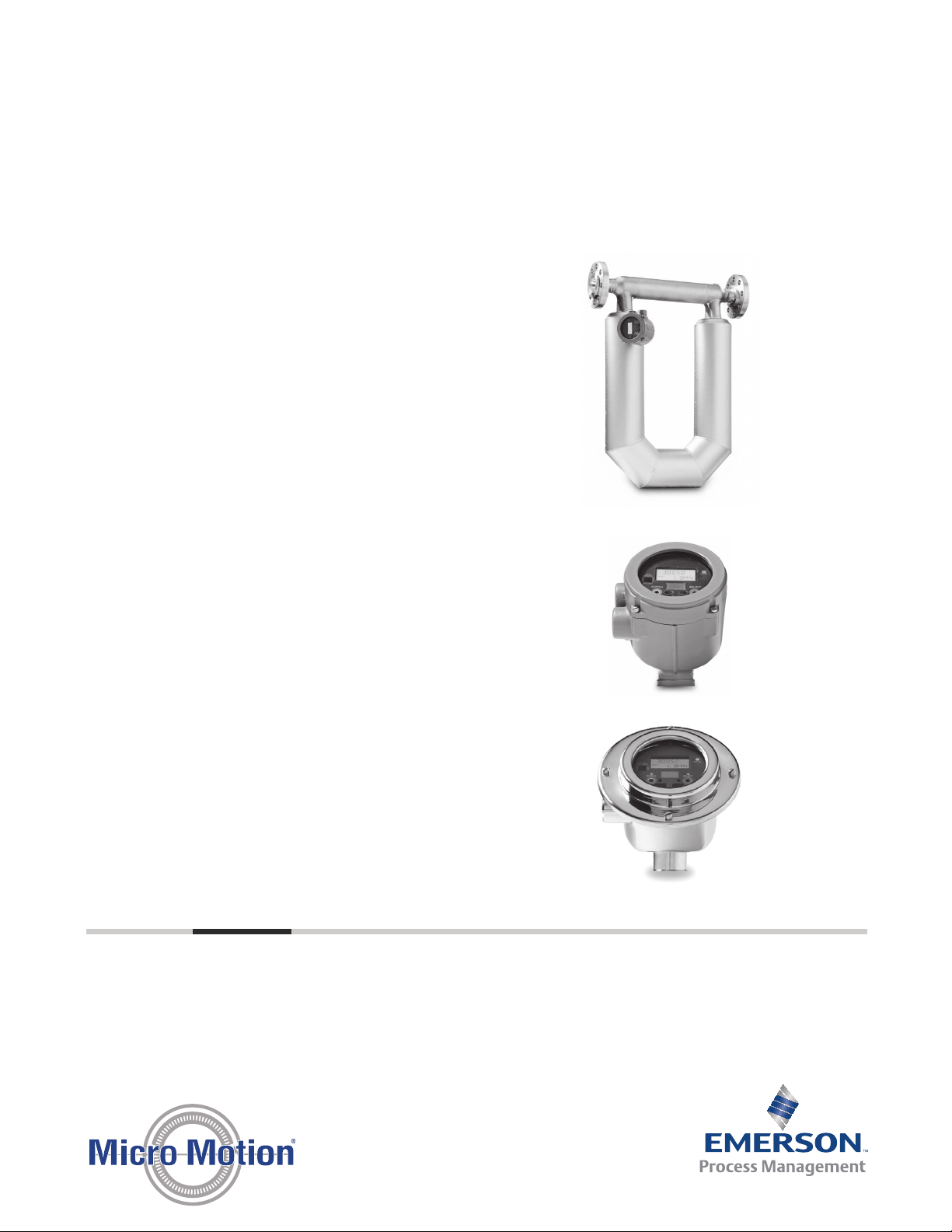
The Model 2400S transmitter provides nextgeneration MVD technology in a compact, spacesaving design. Difficult applications become easy
with ultra-fast meter response time, the ability to
handle high degrees of air entrainment, and built-in
smart diagnostics that alert you to problems before
they impact your process.
Integrated architecture designed for easy access
to process intelligence
Provides extensive built-in diagnostics for
proactive viewing of process events
Enables Smart Meter Verification for quick,
complete meter diagnosis without process
interruption.
Supports PROFIBUS-DP and DeviceNet™
communication protocols for seamless
connectivity
Superior performance in the most challenging
applications
Delivers best two-phase flow capability for
batching, loading, and entrained air applications
Ultra-fast signal processing unlocks unmatched
measurement performance
6
&RPSDFWLQWHJUDO
ZLUHWUDQVPLWWHU
6
&RPSDFWLQWHJUDO
WUDQVPLWWHU
$GYDQFHGILHOG
PRXQWWUDQVPLWWHU
&RPSDFWFRQWURO
URRPWUDQVPLWWHU
)UHTXHQF\LQSXW
GLVFUHWHFRQWUROOHU
,QWHJUDWHGFRQWURO
DQGPHDVXUHPHQWSODWIRUP
9HUVDWLOHILHOG
PRXQWWUDQVPLWWHU
PS-00829, Rev. G
Micro Motion® Model 2400S Transmitters
with MVDTM Technology
May 2015
Page 2

Model 2400S Transmitter with MVD™ Technology
Table of contents
Input/output signal detail ............................................. 3
Electrical connections ...................................................3
Power supply .................................................................5
Environmental limits..................................................... 5
Environmental effects ...................................................6
Hazardous area classifications ....................................... 6
Physical specifications ................................................... 7
Dimensions ................................................................. 11
Ordering Information .................................................. 13
May 2015
Micro Motion Model 2400S transmitters
Micro Motion transmitters and controllers from Emerson Process Management utilize MVD technology to
deliver accurate, high-speed multivariable signals. Micro Motion transmitters are available with a wide
selection of communication protocols, including 4–20 mA, HART
DeviceNet
™
, Modbus®, and more. That means you will always be able to receive the process information you
need in a format that works for your installation. Micro Motion transmitters also carry advanced diagnostic
tools, allowing you to rest easy knowing your process is being monitored correctly.
®
, Foundation™ fieldbus, PROFIBUS,
MVD technology
MVD technology makes your Micro Motion
flowmeter work smarter. Front-end digital
processing dramatically reduces signal noise and
gives you faster response time compared to analog
devices.
Only MVD technology allows you to:
Measure multiple variables for accurate process
control
Identify and resolve problems easily with built-in
smart diagnostics
Flexible architecture enables tuning for your
application needs
Upgrade transmitter functionality as needed,
without impacting availability
Model 2400S transmitters
The Micro Motion Model 2400S transmitter is
leading the way among MVD transmitters. The
Mode 2400S transmitter provides next-generation
performance in an innovative, compact package,
integrally mounted on a Micro Motion meter.
Difficult applications become easy with ultra-fast
meter response time, the ability to handle high
degrees of air entrainment, and built-in smart
diagnostics that alert you to problems before they
impact your process.
The Model 2400S transmitter is available with a
range of communication options: analog channels
or digital communication with PROFIBUS-DP or
DeviceNet protocols.
The Model 2400S raises the bar in process
measurement by providing outstanding out-of-thebox performance unequaled by any other
manufacturer or technology.
2 www.micromotion.com
Page 3

May 2015
Model 2400S Transmitter with MVD™ Technology
Electrical connections
Connection type Model 2400S Analog Model 2400S PROFIBUS-DP Model 2400S DeviceNet
Input/Output Two pairs of wiring terminals
PROFIBUS-DP segment One pair of wiring terminals for
DeviceNet segment One pre-installed male 5-pin
Power One pair of wiring terminals
Service port Two clips for temporary
for transmitter inputs/
outputs. Screw terminals
accept solid or stranded
conductors, 26 to 14 AWG
(0.14 to 2.5 mm
2
).
accepts AC or DC power. One
internal ground lug for power
supply ground wiring.
Screw terminals accept solid
or stranded conductors, 26 to
14 AWG (0.14 to 2.5 mm
2
).
connection to the service port.
Two clips for temporary
connection to HART/Bell 202
terminals
connection to PROFIBUS-DP
segment. Connection type:
Screw terminals accept solid
or stranded conductors, 26
to 14 AWG (0.14 to 2.5
2
).
mm
Five-pin PROFIBUS-DP M12
(Eurofast) female connector
(optional).
One pair of wiring terminals
accepts AC or DC power. One
internal ground lug for power
supply ground wiring.
Screw terminals accept solid or
stranded conductors, 26 to 14
AWG (0.14 to 2.5 mm2).
Two clips for temporary
connection to the service port.
Eurofast connector for I/O and
power supply wiring.
Two clips for temporary
connection to the service port.
Input/output signal detail
Model Descriptions
Model 2400S Analog
Channel A
www.micromotion.com 3
One active or passive 4–20 mA output
Not intrinsically safe
Isolated to ±50 VDC from all other outputs and earth ground
Maximum load limit: 820 ohms
External (passive) power: 12 to 30 VDC, 24 VDC typical
Can report mass flow, volume flow, density, temperature, or drive gain
Output is linear with process from 3.8 to 20.5 mA, per NAMUR NE43 (February 2003)
Page 4

Model 2400S Transmitter with MVD™ Technology
Input/output signal detail (Continued)
Model Descriptions
Model 2400S Analog
Channel B (configurable)
Model 2400S PROFIBUS-DP Digital 2-way PROFIBUS-DP signal.
Model 2400S DeviceNet Digital 2-way DeviceNet signal.
One active or passive frequency/pulse output
Not intrinsically safe
Can report mass flow or volume flow, which can be used to indicate flow rate or total
Scalable to 10,000 Hz
Power:
- Internal (active): +24 VDC ±3% with a 2.2 kohm internal pull-up resistor
- External (passive): +30 VDC maximum, +24 VDC typical (external pull-up required)
Output is linear with flow rate to 12,500 Hz
Maximum sink capability: 500 mA
One active or passive discrete output
Not intrinsically safe
Can report five discrete events, flow switch, forward/reverse flow, calibration in progress, or
fault
Power:
- Internal (active): +24 VDC ±3% with a 2.2 kohm internal pull-up resistor
- External (passive): +30 VDC maximum, +24 VDC typical
Maximum sink capability: 500 mA
One active or passive discrete input
Not intrinsically safe
Power:
- Internal (active): +24 VDC, 10 mA maximum source current
- External (passive): +3 to 30VDC maximum
Can reset all totals, reset mass total, reset volume total, start/stop totals, or start sensor zero
Certified by Profibus User Organization (PNO).
Certified by Open DeviceNet Vendor Association (ODVA).
May 2015
Digital communications
Output type Outputs and descriptions
Service port
(all versions)
Wireless
(all versions)
HART/Bell 202
(Model 2400S Analog)
4 www.micromotion.com
One service port for temporary connections (requires removing transmitter housing cover)
Uses RS-485 Modbus signal, 38.4 kilobaud, one stop bit, no parity
Address: 111 (not configurable)
If transmitter has display, service port can be accessed via serial port IrDA without removing
transmitter housing cover.
HART signal is superimposed on the milliamp output (Channel A), and is available for host system
interface:
Frequency: 1.2 and 2.2 kHz
Amplitude: to 1.2 mA
1200 baud, one stop bit, odd parity
Address: 0 (default), configurable
Requires 250 to 600 W resistance
Page 5
May 2015
Model 2400S Transmitter with MVD™ Technology
Digital communications (Continued)
Output type Outputs and descriptions
PROFIBUS-DP
(Model 2400S PROFIBUS-DP)
DeviceNet
(Model 2400S DeviceNet)
Digital 2-way communication protocol
Automatically recognizes network baud rate
Address selectable by 3 rotary switches, or software selectable
Digital 2-way communication protocol
Address and baud rate selectable by 3 rotary switches (2 to select address, 1 to select baud
rate), or software selectable
Power supply
Analog and PROFIBUS-DP
type Description
Self-switching AC/DC input, automatically recognizes supply voltage.
Complies with low voltage directive 2006/95/EC per EN 61010-1 (IEC 61010-1).
Installation (Overvoltage) Category II, Pollution Degree 2.
AC
DC 18-100 VDC
Fuse
85-265 VAC
50/60 Hz
4 watts typical, 7 watts maximum
4 watts typical, 7 watts maximum
IEC 127-1.25 fuse, slow blow
Environmental limits
Environmental factor °F °C
Ambient temperature limits Operating –40 to +140 –40 to +60
Storage –40 to +158 –40 to +70
Below –4 °F (–20 °C), LCD responsiveness decreases and LCD may become difficult to read. Above
131 °F (55 °C), some darkening of the LCD panel might occur
Humidity limits 5 to 95% relative humidity, non-condensing at 140 °F (60 °C)
Vibration limits Meets IEC 60068-2-6, endurance sweep, 5 to 2000 Hz, 50 sweep cycles at 1.0 g
Housing rating NEMA 4X (IP66/67) polyurethane-painted cast aluminum or 316L stainless steel
www.micromotion.com 5
Page 6

Model 2400S Transmitter with MVD™ Technology
Environmental effects
EMI effects
For all models:
Complies with EMC directive 2004/108/EC per EN 61326 Industrial
Conforms to NAMUR NE21 Version: 08.22.2007
Ambient temperature effect
For Model 2400S Analog:
On mA output: ±0.005% of span per °C
Hazardous area classifications
Model 2400S Analog
May 2015
CSA C-US
Class I Division 2 Groups A, B, C, D
Class II Division 2 Groups F and G
ATEX
II 3 G Ex nAC II T5 (Zone 2)
II 3 D IP66/IP67 T70°C
IECEx
Ex nAC II T5
INMETRO
BR-Ex nAC IIC T5
–40 °C Ta +60 °C
Model 2400S PROFIBUS-DP
CSA C-US
Class I Division 2 Groups A, B, C, D
Class II Division 2 Groups F and G
ATEX
II 3 G Ex nAC II T5 (Zone 2)
II 3 D IP66/IP67 T70°C
IECEx
Ex nAC II T5
6 www.micromotion.com
Page 7

May 2015
Model 2400S Transmitter with MVD™ Technology
Model 2400S DeviceNet
CSA C-US
Class I Division 2 Groups A, B, C, D
Class II Division 2 Groups F and G
IECEx
Ex nAC II T5
Physical specifications
All models
Specification Value
Housing NEMA 4X (IP66/67) polyurethane-painted cast aluminum or 316L stainless steel.
Weight Transmitter is mounted integrally with sensor. For weight of flowmeter, see product data
Mounting
With or without display Suitable for hazardous area installation.
With display Depending on purchase option, transmitter housing cover has glass or plastic lens.
Without display
sheet for sensor.
Integral-mount or extended-mount
Available integrally mounted to Micro Motion ELITE and F-Series sensors
The transmitter can be rotated on the mounting in 45° increments, for eight different
orientations.
User interface module can rotate 360° on the transmitter in 90° increments.
Three-color status LED on user interface module indicates flowmeter condition at a
glance, using a solid green, yellow, or red light. Zero in progress is indicated by a flashing
yellow light.
Two clips for service port connections (requires removing transmitter housing cover).
User interface module includes LCD panel. LCD line 1 displays process variable; line 2
displays engineering unit of measure.
Display update rate is user-configurable: 1 to 10 seconds at 1-second increments.
Display backlighting may be adjusted or turned off.
Operator access to transmitter menus is provided via optical switches that are operated
through the lens. LED indicators show when a “button” has been pressed.
Infrared port allows access to service port from serial port IrDA without removing
transmitter housing cover.
Transmitter housing cover is all metal (no lens).
Access to user interface requires removing transmitter housing cover.
Zero button allows flowmeter zero from field (requires removing transmitter housing
cover).
No IrDA port.
www.micromotion.com 7
Page 8

Model 2400S Transmitter with MVD™ Technology
May 2015
Model 2400S Analog
Specification Value
With or without display Two clips for HART/Bell 202 connections (requires removing transmitter housing cover).
HART security switch (requires removing transmitter housing cover).
With display
Without display
8 www.micromotion.com
Page 9

May 2015
Model 2400S Transmitter with MVD™ Technology
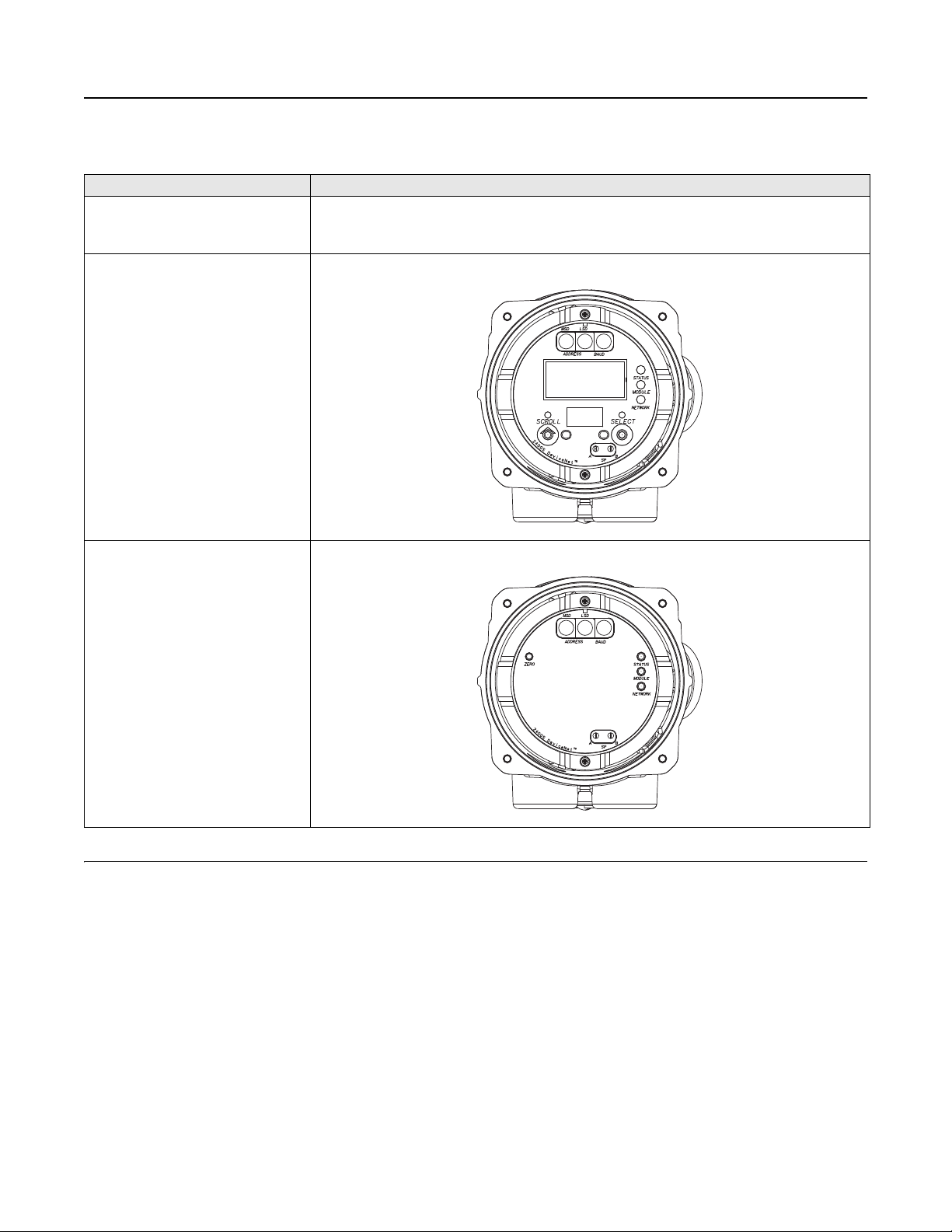
Model 2400S PROFIBUS-DP
Specification Value
With or without display Three rotary switches for selecting network address (network address is also software-
selectable).
DIP switch for enabling internal termination resistor.
Address and network LEDs that indicate PROFIBUS-DP status.
With display
Without display
www.micromotion.com 9
Page 10
Model 2400S Transmitter with MVD™ Technology
May 2015
Model 2400S DeviceNet
Specification Value
With or without display Three rotary switches for selecting network address and baud rate (network address and
baud rate are also software-selectable).
Module and network LEDs to indicate DeviceNet status.
With display
Without display
10 www.micromotion.com
Page 11

Model 2400S Transmitter with MVD™ Technology
Dimensions in
inches
(mm)
4.545
(115,4)
3.140
(79,7)
3.140
(79,7)
4.689
(119,1)
.800
(20,3)
1.600
(40,6)
4.344
(110,3)
Dimensions
Dimensions for painted aluminum housing
PS-00829, Rev. G
Product Data Sheet
Page 12

Model 2400S Transmitter with MVD™ Technology
Dimensions in
inches
(mm)
5.70
(114,8)
5.20
(132,1)
5.70
(114,8)
5.20
(132,1)
0.793
(20,1)
1.586
(40,3)
4.515
(114,7)
Dimensions for stainless steel housing
May 2015
12 www.micromotion.com
Page 13

May 2015
Mo
u
n
t
i
n
g
Transmitter
base model
P
o
w
e
r
I
/
O
t
e
r
m
i
n
a
t
i
o
n
s
D
i
s
p
l
a
y
C
o
n
d
u
i
t
c
o
n
n
e
c
t
i
o
n
s
A
p
p
r
o
v
a
l
s
L
a
n
g
u
a
g
e
S
o
f
t
w
a
r
e
o
p
t
i
o
n
s
1
S
o
f
t
w
a
r
e
o
p
t
i
o
n
s
2
F
a
c
t
o
r
y
o
p
t
i
o
n
s
Model 2400S Transmitter with MVD™ Technology
Ordering information
Product code structure for Model 2400S
Base model
Model Product description
2400S Micro Motion Coriolis MVD transmitter. Must be ordered with a sensor.
Mounting
Code Mounting options
I Integral mount transmitter, polyurethane-painted aluminum
(1)
J
(1) Not recommended for truck-mount
Integral mount transmitter, 316L stainless steel
Power
Code Output options / power supply
A One mA, one configurable output / 18 to 100 VDC and 85 to 265 VAC, self-switching
(1)
C
D PROFIBUS-DP / 18 to 100 VDC and 85 to 265 VAC, self switching
(1) Requires selecting conduit connection option L or M.
DeviceNet (bus powered))
I/O terminations
Code I/O termination option
1 Compression screw terminals
Display
Code Transmitter display options
1 Dual-line display for process variables and totalizer reset
3No display
(1)
4
(1) Not available with approval codes 2, L, 3, or G with country-specific approval R3, B3.
Non-glass dual line display for process variables and totalizer reset
www.micromotion.com 13
Page 14

Model 2400S Transmitter with MVD™ Technology
Conduit connections
Code Conduit connection options
B 1/2-inch NPT — no gland
C 1/2-inch NPT with brass/nickel cable gland
D 1/2-inch NPT with stainless steel cable gland
E M20 — no gland
F M20 with brass/nickel cable gland
G M20 with stainless steel cable gland
L DeviceNet 5-pin Eurofast connector in M20 housing
M DeviceNet 5-pin Eurofast connector in 1/2-inch NPT housing
Approvals
Code Terminal options
M Micro Motion standard (no approval with CE/EAC markings)
2 CSA Class I Div. 2 (U.S.A. and Canada)
(1)
L
(1)
3
(1) (2)
G
(1) Not available with approval codes 2, L, 3, or G with country-specific approval R3, B3.
(2) Requires a selection from the Approvals section of the “Add on Options”.
ATEX II 3, Zone 2
IECEx Zone 2
County-specific approval – Requires a selection in the Add-on options table
May 2015
Language
Code Display and documentation language
A Danish installation manual and English configuration manual
D Dutch installation manual and English configuration manual
E English installation manual and English configuration manual
F French installation manual and French configuration manual
G German installation manual and German configuration manual
H Finnish installation manual and English configuration manual
I Italian installation manual and English configuration manual
J Japanese installation manual and English configuration manual
M Chinese installation manual and Chinese configuration manual
N Norwegian installation manual and English configuration manual
P Portuguese installation manual and English configuration manual
S Spanish installation manual and Spanish configuration manual
W Swedish installation manual and English configuration manual
C Czech CE requirements, English installation manual, and English configuration manual
B Hungarian CE requirements, English installation manual, and English configuration manual
K Slovak CE requirements, English installation manual, and English configuration manual
T Estonian CE requirements, English installation manual, and English configuration manual
O Polish CE requirements, English installation manual, and English configuration manual
U Greek CE requirements, English installation manual, and English configuration manual
L Latvian CE requirements, English installation manual, and English configuration manual
V Lithuanian CE requirements, English installation manual, and English configuration manual
Y Slovenian CE requirements, English installation manual, and English configuration manual
14 www.micromotion.com
Page 15

May 2015
Model 2400S Transmitter with MVD™ Technology
Software options 1
Code Software options 1
Z No software options 1
(1)
G
(1)
A
(1) Software options A and G are available only with power option codes C and D.
Enhanced density measurement
Petroleum measurement
Software options 2
Code Software options 2
Z No software options 2
C Smart Meter Verification
Factory options
Code Factory options
ZStandard product
XETO product
Add-on options
Code Add-on options (optional)
GH PROFIBUS-DP Eurofast M12 SST 5-pin Connector, M20
GI PROFIBUS-DP DP Eurofast M12 SST 5-pin Connector, 1/2-inch NPT
County-specific approvals. Must select only one when approval option G is selected.
(1) (2)
R3
(1)
B3
(1) Not available with approval codes 2, L, 3, or G with country-specific approval R3, B3.
(2) Available with only approval G.
EAC Zone 2 – Hazardous area approval
INMETRO Zone 2 – Hazardous area approval
www.micromotion.com 15
Page 16

Model 2400S Transmitter with MVD™ Technology
A
Emerson Process Management
Asia Pacific
A
© 201Micro Motion, Inc. All rights reserved.
The Emerson logo is a trademark and service mark of Emerson Electric Co. Micro Motion, ELITE, ProLink, MVD and MVD Direct Connect marks are
marks of one of the Emerson Process Management family of companies. All other marks are property of their respective owners.
Micro Motion supplies this publication for informational purposes only. While every effort has been made to ensure accuracy, this publication is not
intended to make performance claims or process recommendations. Micro Motion does not warrant, guarantee, or assume any legal liability for the
accuracy, completeness, timeliness, reliability, or usefulness of any information, product, or process described herein. We reserve the right to
modify or improve the designs or specifications of our products at any time wihout notice. For actual product information and recommendations,
please contact your local Micro Motion representative.
PS-00829, Rev. G
Product Data Sheet
Emerson Process Management
Americas
7070 Winchester Circle
Boulder, Colorado USA 80301 Dubai
www.MicroMotion.com Abu Dhabi
www.Rosemount.com
T: +1 800 522 6277 Germany T: 0800 182 5347
T: +1 (303) 527 5200 Italy T: 8008 77334
F: +1 (303) 530 8459
Mexico T: 52 55 5809 5300 Spain
rgentina T: 54 11 4837 7000 U.K. T: 0870 240 1978
Brazil T: 55 15 3413 8000 Russia/CIS
Venezuela T: 58 26 1300 8100
Chile T: 56 2 2928 4800
Emerson Process Management
Europe/Mi ddle East
Central & Eastern Europe T: +41 41 7686 111
France T: 0800 917 901
The Netherlands
Belgium
T: +971 4 811 8100
T: +971 2 697 2000
T: +31 (0) 70 413 6666
T: +32
2 716 77 11
T: +34 913 586 000
T: +7 495 981 9811
ustralia T: (61) 3 9721 0200
China
India
Japan
South Korea
Singapore
T: (86) 21 2892 9000
T: (91)
22 6662 0566
T: (81)
3 5769 6803
T: (82)
2 3438 4600
T: (65)
6 777 8211
 Loading...