

Page 1
Micro Motion® Model 1700 and 2700
Installation Manual
Installation Manual
20001700, Rev CE
May 2015
Page 2

Safety messages
Safety messages are provided throughout this manual to protect personnel and equipment. Read each safety message carefully
before proceeding to the next step.
Emerson Flow customer service
Email:
• Worldwide: flow.support@emerson.com
• Asia-Pacific: APflow.support@emerson.com
Telephone:
North and South America Europe and Middle East Asia Pacific
United States 800-522-6277 U.K. 0870 240 1978 Australia 800 158 727
Canada +1 303-527-5200 The Netherlands +31 (0) 704 136 666 New Zealand 099 128 804
Mexico +41 (0) 41 7686 111 France 0800 917 901 India 800 440 1468
Argentina +54 11 4837 7000 Germany 0800 182 5347 Pakistan 888 550 2682
Brazil +55 15 3413 8000 Italy 8008 77334 China +86 21 2892 9000
Venezuela +58 26 1731 3446 Central & Eastern +41 (0) 41 7686 111 Japan +81 3 5769 6803
Russia/CIS +7 495 981 9811 South Korea +82 2 3438 4600
Egypt 0800 000 0015 Singapore +65 6 777 8211
Oman 800 70101 Thailand 001 800 441 6426
Qatar 431 0044 Malaysia 800 814 008
Kuwait 663 299 01
South Africa 800 991 390
Saudi Arabia 800 844 9564
UAE 800 0444 0684
Page 3

Contents
Contents
Chapter 1 Planning .........................................................................................................................1
1.1 Meter components ...................................................................................................................... 1
1.2 Installation types ..........................................................................................................................1
1.3 Maximum cable lengths between sensor and transmitter ............................................................ 6
1.4 Output options ............................................................................................................................ 7
1.5 Environmental limits .................................................................................................................... 8
1.6 Hazardous area classifications ......................................................................................................8
1.7 Power requirements .................................................................................................................... 8
1.8 Orientation .................................................................................................................................. 9
1.9 Accessibility for maintenance .....................................................................................................10
Chapter 2 Mounting and sensor wiring for integral installations ...................................................11
2.1 Mounting and sensor wiring .......................................................................................................11
2.2 Rotate the transmitter on the sensor (optional) ......................................................................... 11
2.3 Rotate the user interface on the transmitter (optional) .............................................................. 13
2.4 Ground the meter components ................................................................................................. 14
Chapter 3 Mounting and sensor wiring for 4-wire remote installations .........................................16
3.1 Mounting options ...................................................................................................................... 16
3.2 Prepare the 4-wire cable ............................................................................................................ 20
3.3 Wire the transmitter to the sensor ............................................................................................. 23
3.4 Rotate the user interface on the transmitter (optional) .............................................................. 25
3.5 Ground the meter components ................................................................................................. 26
Chapter 4 Mounting and sensor wiring for 9-wire remote installations .........................................28
4.1 Mounting options ...................................................................................................................... 28
4.2 Prepare the 9-wire cable ............................................................................................................ 30
4.3 Wire the transmitter to the sensor using jacketed cable .............................................................36
4.4 Wire the transmitter to the sensor using shielded or armored cable ...........................................39
4.5 Rotate the user interface on the transmitter (optional) .............................................................. 44
4.6 Ground the meter components ................................................................................................. 46
Chapter 5 Mounting and sensor wiring for remote core processor with remote sensor
installations ................................................................................................................. 48
5.1 Mounting options ...................................................................................................................... 48
5.2 Mount the remote core processor ..............................................................................................52
5.3 Prepare the 4-wire cable ............................................................................................................ 53
5.4 Wire the transmitter to the remote core processor .................................................................... 56
5.5 Prepare the 9-wire cable ............................................................................................................ 58
5.6 Wire the remote core processor to the sensor using jacketed cable ........................................... 64
5.7 Wire the remote core processor to the sensor using shielded or armored cable ......................... 67
5.8 Rotate the user interface on the transmitter (optional) .............................................................. 71
5.9 Ground the meter components ................................................................................................. 73
Chapter 6 Wiring the power supply ..............................................................................................76
6.1 Wire the power supply ............................................................................................................... 76
Chapter 7 I/O wiring for Model 1700 and Model 2700 transmitters with analog outputs ...............77
7.1 Basic analog wiring .................................................................................................................... 77
7.2 HART/analog single loop wiring ................................................................................................. 78
Installation Manual i
Page 4

Contents
7.3 RS-485 point-to-point wiring ..................................................................................................... 79
7.4 HART multidrop wiring .............................................................................................................. 79
Chapter 8 I/O wiring for Model 1700 and Model 2700 transmitters with intrinsically safe
outputs ........................................................................................................................ 81
8.1 Safe area mA output wiring ........................................................................................................81
8.2 Safe area HART/analog single-loop wiring ..................................................................................82
8.3 Safe area HART multidrop wiring ............................................................................................... 83
8.4 Safe area frequency output/discrete output wiring .................................................................... 84
8.5 Hazardous area wiring ............................................................................................................... 84
Chapter 9 I/O wiring for Model 2700 transmitters with configurable input/outputs ......................90
9.1 Channel configuration ............................................................................................................... 90
9.2 mA/HART wiring ........................................................................................................................ 91
9.3 Frequency output wiring ............................................................................................................93
9.4 Discrete output wiring ............................................................................................................... 97
9.5 Discrete input wiring ................................................................................................................101
Chapter 10 I/O wiring for Model 2700 transmitters with Foundation fieldbus or PROFIBUS-PA ......103
10.1 Foundation fieldbus wiring .......................................................................................................103
10.2 PROFIBUS-PA wiring .................................................................................................................104
Chapter 11 Specifications ............................................................................................................. 105
11.1 Electrical connections .............................................................................................................. 105
11.2 Input/output signals ................................................................................................................ 106
11.3 Local display ............................................................................................................................ 110
11.4 Environmental limits ................................................................................................................111
11.5 Physical specifications ..............................................................................................................111
Index ................................................................................................................................................116
ii Micro Motion® Model 1700 and 2700
Page 5
1 Planning
Topics covered in this chapter:
• Meter components
• Installation types
• Maximum cable lengths between sensor and transmitter
• Output options
• Environmental limits
• Hazardous area classifications
• Power requirements
• Orientation
• Accessibility for maintenance
Planning
1.1 Meter components
The transmitter is one component of a Micro Motion device. The other major component
is the sensor.
A third component, called the core processor, provides additional memory and processing
functions.
1.2 Installation types
The transmitter was ordered and shipped for one of up to eight installation types. The fifth
character of the transmitter model number indicates the installation type.
Installation type indication for Model 1700 and Model 2700 transmittersFigure 1-1:
The model number is located on the device tag on the side of the transmitter.
Installation types for Model 1700 and Model 2700 transmittersTable 1-1:
Model code Description
R Remote mount 4-wire
I Integral
Installation Manual 1
Page 6
A
B
Planning
Installation types for Model 1700 and Model 2700 transmitters (continued)Table 1-1:
Model code Description
E Remote enhanced core processor (painted aluminum housing) with remote
transmitter
C Remote mount 9-wire (painted aluminum housing)
B Remote core processor with remote transmitter
M Remote mount 4-wire (stainless steel housing)
P Remote mount 9-wire (stainless steel housing)
(1)
H
Remote mount 4-wire (painted aluminum housing) for connecting to Compact Density Meter (CDM), Fork Density Meter (FDM), Fork Viscosity Meter
(FVM)
(1) This option is only available with the Model 2700 FOUNDATION Fieldbus™ transmitter
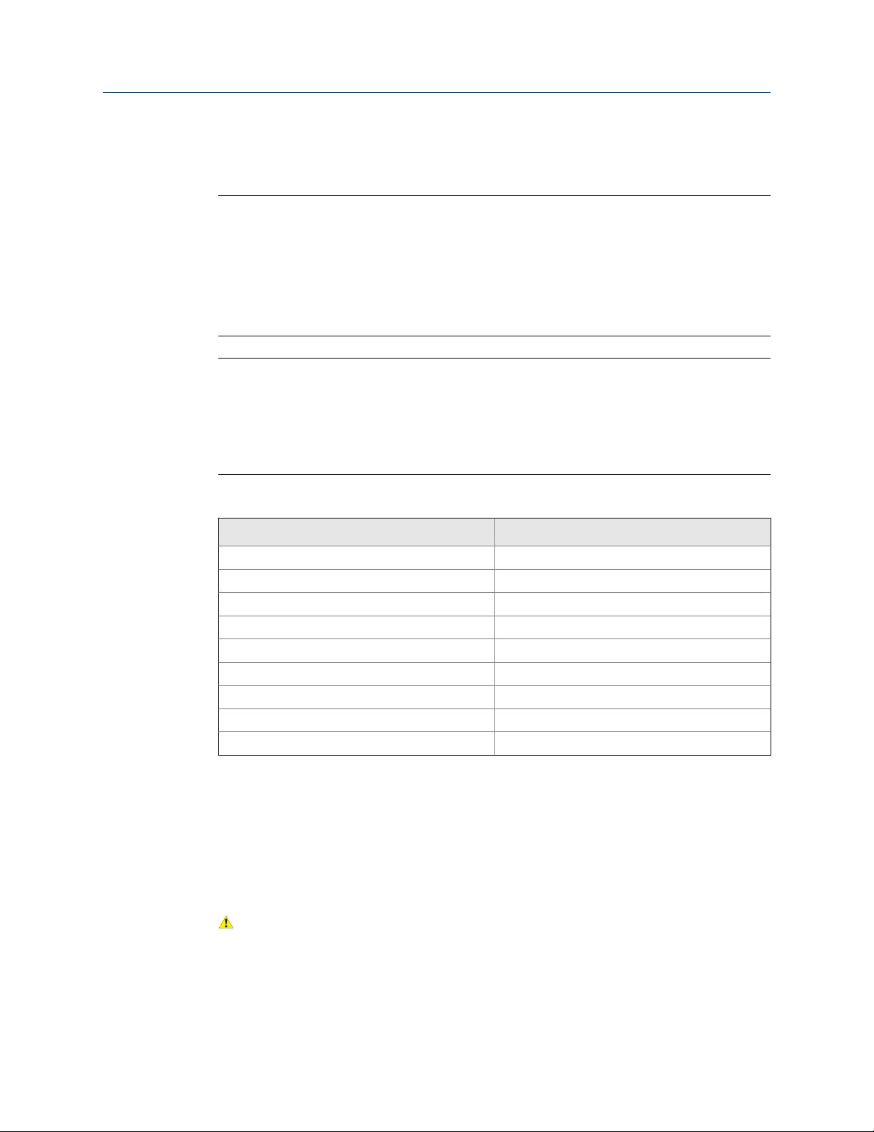
Integral installation (model code I)Figure 1-2:
The transmitter is mounted directly to the sensor. Integral installations do not require separate transmitter
installation. Power supply and I/O must be field wired to the transmitter.
A. Transmitter
B. Sensor
2 Micro Motion® Model 1700 and 2700
Page 7
Planning
High-temperature meters with factory connection (model code I)Figure 1-3:
The transmitter is shipped with a flexible connection factory installed between the sensor and the
transmitter. The transmitter must be dismounted from its shipping location (spot-welded to the sensor
case) and then mounted separately. Power supply and I/O must be field wired to the transmitter.
A
B
C
A. Sensor
B. Transmitter or core processor
C. Factory-installed flexible connection
4-wire remote installation for Coriolis meters (model code R or M)Figure 1-4:
The transmitter is installed remotely from the sensor. The 4-wire connection between the sensor and
transmitter must be field wired. Power supply and I/O must be field wired to the transmitter.
A
B
C
D
A
A. Transmitter
B. Field-wired 4-wire connection
C. Core processor
D. Sensor
Installation Manual 3
Page 8
Planning
Figure 1-5:
4-wire remote installation for density and viscosity meters (CDM, FDM,
or FVM with fieldbus only)(model code H)
The transmitter is installed remotely from the Compact Density Meter (CDM), Fork Density Meter (FDM), or
Fork Viscosity Meter (FVM). The 4-wire connection between the sensor and transmitter must be field wired.
Power supply and I/O must be field wired to the transmitter.
A
B
C
A. Transmitter
B. Field-wired 4-wire connection
C. Meter electronics
4 Micro Motion® Model 1700 and 2700
Page 9
Planning
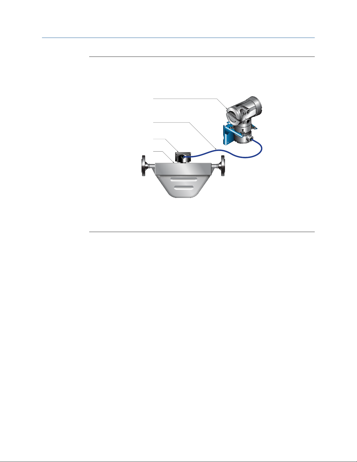
9-wire remote installation (model code P)Figure 1-6:
The transmitter and core processor are combined in a single unit that is installed remotely from the sensor.
The 9-wire connection between the transmitter/core processor and the sensor must be field wired. Power
supply and I/O must be field wired to the transmitter.
A
B
C
D
A
A. Transmitter
B. Field-wired 9-wire connection
C. Junction box
D. Sensor
Installation Manual 5
Page 10
Planning
Figure 1-7:
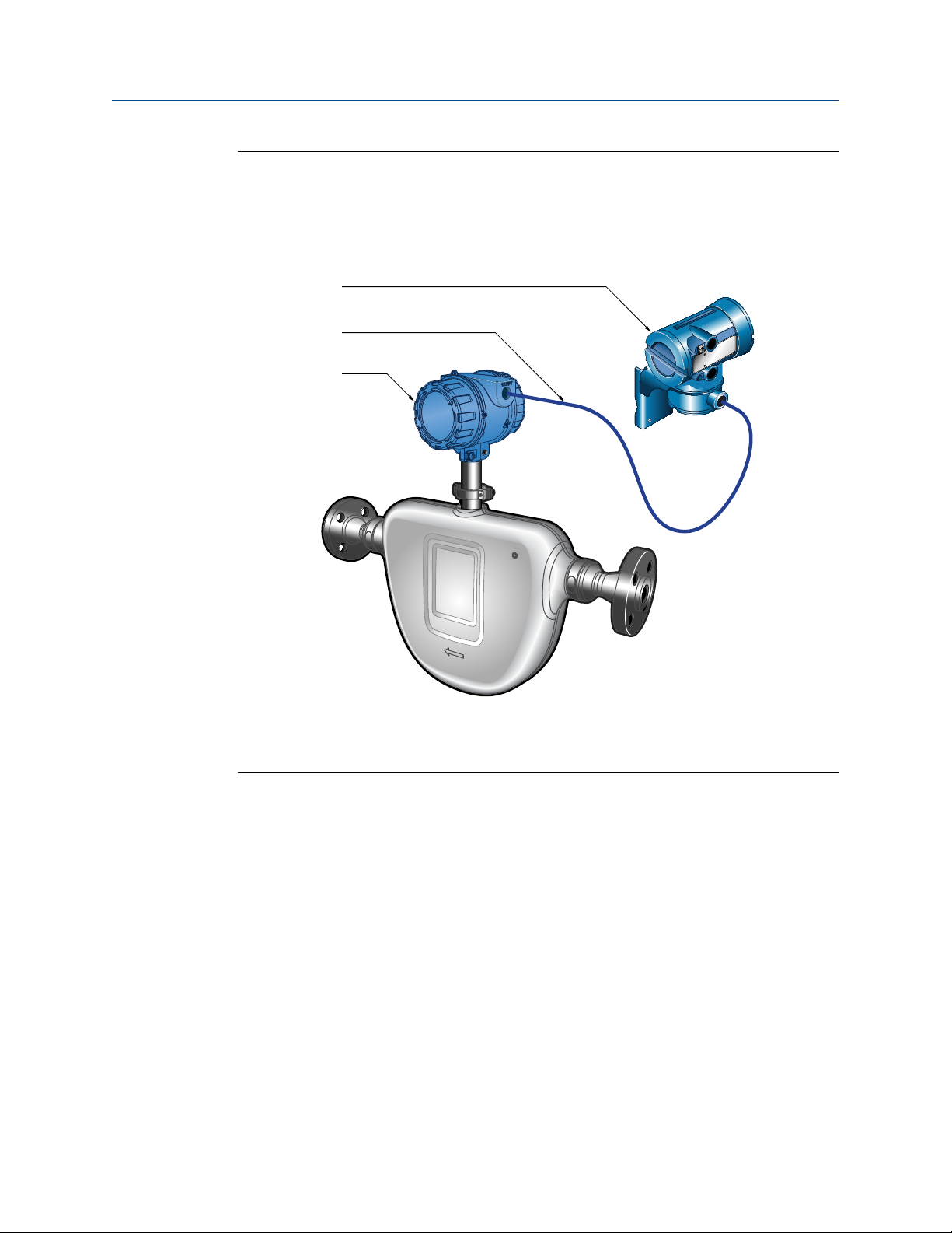
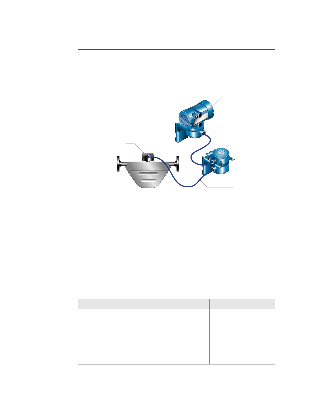
Remote core processor with remote sensor installation (model code B or
E)
The transmitter, core processor, and sensor are all mounted separately. The 4-wire connection between
the transmitter and core processor must be field wired. The 9-wire connection between the core processor
and the sensor must be field wired. Power supply and I/O must be field wired to the transmitter. This
configuration is sometimes called double-hop.
C
D
A
B
A. Junction box
B. Sensor
C. Transmitter
D. Field-wired 4-wire connection
E. Core processor
F. Field-wired 9-wire connection
E
F
1.3 Maximum cable lengths between sensor and
transmitter
The maximum cable length between the sensor and transmitter that are separately
installed is determined by cable type.
Maximum cable lengths between sensor and transmitterTable 1-2:
Cable type Wire gauge Maximum length
Micro Motion 4-wire Not applicable • 1000 ft (300 m) without Ex-
approval
• 500 ft (150 m) with IIC rat-
ed sensors
• 1000 ft (300 m) with IIB rat-
ed sensors
Micro Motion 9-wire Not applicable 60 ft (20 m)
User-supplied 4-wire VDC 22 AWG (0.35 mm2) 300 ft (90 m)
6 Micro Motion® Model 1700 and 2700
Page 11
Maximum cable lengths between sensor and transmitter (continued)Table 1-2:
Cable type Wire gauge Maximum length
1.4 Output options
The transmitter was ordered and shipped for one of up to 10 output options. You must
know your transmitter output option to correctly install the transmitter. The eighth
character of the transmitter model number indicates the output option.
Output option indication for Model 1700 and Model 2700 transmittersFigure 1-8:
VDC 20 AWG (0.5 mm2) 500 ft (150 m)
VDC 18 AWG (0.8 mm2) 1000 ft (300 m)
RS-485 22 AWG (0.35 mm2) or
larger
1000 ft (300 m)
Planning
The model number is located on the device tag on the side of the transmitter.
Output options for Model 1700 transmittersTable 1-3:
Letter Description
A Analog outputs – one mA, one frequency, one RS-485
D Intrinsically safe analog outputs – two mA, one frequency
Output options for Model 2700 transmittersTable 1-4:
Letter Description
A Analog outputs – one mA, one frequency, one RS-485
B Configurable I/O channels (default configuration of two mA, one frequency)
C Configurable I/O channels (custom configuration )
D Intrinsically safe analog outputs – two mA, one frequency
E Intrinsically safe Foundation fieldbus H1 with standard function blocks
G PROFIBUS-PA
N Non-incendive Foundation fieldbus H1 with standard function blcoks
2 WirelessHART – one mA, one frequency, one RS-485
Installation Manual 7
Page 12

Planning
Output options for Model 2700 transmitters (continued)Table 1-4:
Letter Description
3 WirelessHART – one mA, two configurable I/O channels (custom configura-
tion)
4 Intrinsically safe WirelessHART – two mA, one frequency
1.5 Environmental limits
Environmental specificationsTable 1-5:
Type Value
Ambient temperature limits –40 to +140 °F (–40 to +60 °C)
Humidity limits 5 to 95% relative humidity, non-condensing at 140 °F (60 °C)
Vibration limits Meets IEC 60068-2-6, endurance sweep, 5 to 2000 Hz, 50 sweep
cycles at 1.0 g
EMI effects Complies with EMC Directive 2004/108/EC per EN 61326 Indus-
trial
Complies with NAMUR NE-21 (22.08.2007)
Ambient temperature effect on
analog outputs
On mA output: ±0.005% of span per °C
If possible, install the transmitter in a location that will prevent direct exposure to sunlight.
The environmental limits for the transmitter may be further restricted by hazardous area
approvals.
1.6 Hazardous area classifications
If you plan to mount the transmitter in a hazardous area:
• Verify that the transmitter has the appropriate hazardous area approval. Each
transmitter has a hazardous area approval tag attached to the transmitter housing.
• Ensure that any cable used between the transmitter and the sensor meets the
hazardous area requirements.
1.7 Power requirements
Self-switching AC/DC input, automatically recognizes supply voltage
• 85 to 265 VAC, 50/60 Hz, 6 watts typical, 11 watts maximum
• 18 to 100 VDC, 6 watts typical, 11 watts maximum
8 Micro Motion® Model 1700 and 2700
Page 13
M = 18V + (R × L × 0.5A)
Planning
• Complies with low voltage directive 2006/95/EC per EN 61010-1 (IEC 61010-1) with
amendment 2, and Installation (Overvoltage) Category II, Pollution Degree 2
Note
For DC power:
• Power requirements assume a single transmitter per cable.
• At startup, the power source must provide a minimum of 1.5 amps of short-term current per
transmitter.
• Length and conductor diameter of the power cable must be sized to provide 18 VDC
minimum at the power terminals, at a load current of 0.5 amps.
Cable sizing formulaFigure 1-9:
• M: minimum supply voltage
• R: cable resistance
• L: cable length
Typical power cable resistance at 68 °F (20 °C)Table 1-6:
Wire gauge Resistance
14 AWG 0.0050 Ω/ft
16 AWG 0.0080 Ω/ft
18 AWG 0.0128 Ω/ft
20 AWG 0.0204 Ω/ft
2.5 mm
1.5 mm
1.0 mm
0.75 mm
0.50 mm
2
2
2
2
2
1.8 Orientation
You can mount the transmitter in any orientation as long as the conduit openings do not
point upward.
0.0136 Ω/m
0.0228 Ω/m
0.0340 Ω/m
0.0460 Ω/m
0.0680 Ω/m
Upward-facing conduit openings risk condensation moisture entering the transmitter housing,
which could damage the transmitter.
Installation Manual 9
CAUTION!
Page 14

Planning
1.9 Accessibility for maintenance
Mount the meter in a location and orientation that satisfies the following conditions:
• Allows sufficient clearance to open the transmitter housing cover. Micro Motion
recommends 8–10 inches (200–250 mm) clearance at the rear of the transmitter.
• Provides clear access for installing cabling to the transmitter.
10 Micro Motion® Model 1700 and 2700
Page 15

Mounting and sensor wiring for integral installations
2 Mounting and sensor wiring for
integral installations
Topics covered in this chapter:
• Mounting and sensor wiring
• Rotate the transmitter on the sensor (optional)
• Rotate the user interface on the transmitter (optional)
• Ground the meter components
2.1 Mounting and sensor wiring
There are no separate mounting requirements for integral transmitters, and no need to
connect wiring between the transmitter and the sensor.
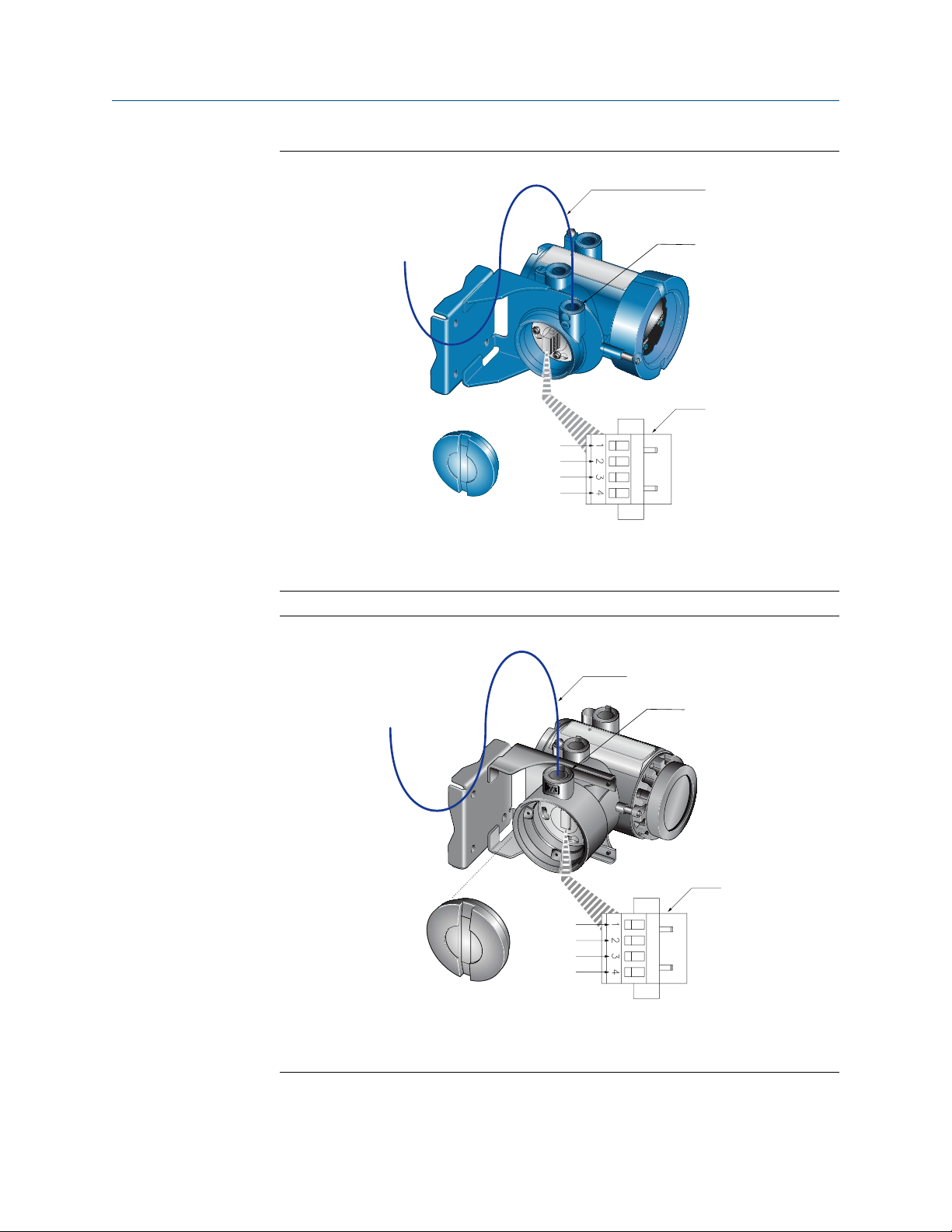
2.2 Rotate the transmitter on the sensor (optional)
In integral installations, you can rotate the transmitter on the sensor up to 360º in 90º
increments.
Installation Manual 11
Page 16
A
B
C
D
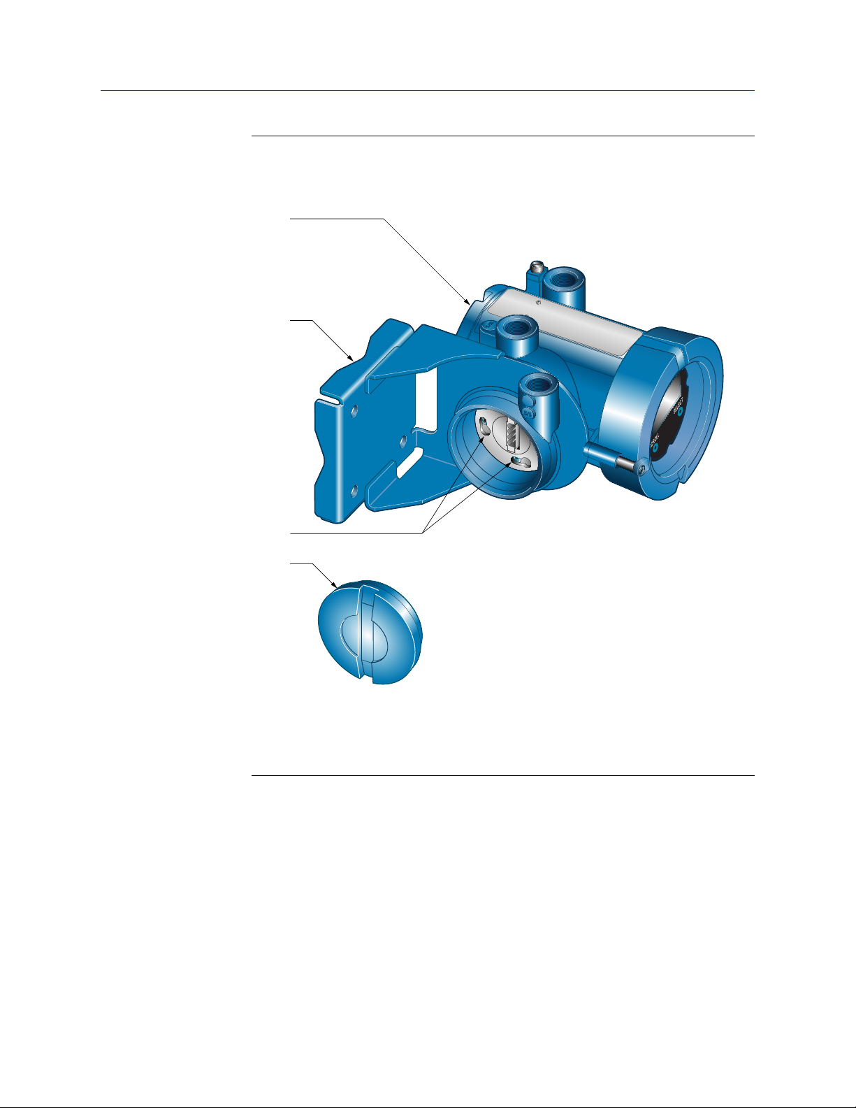
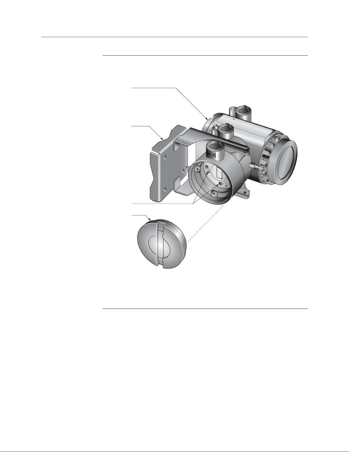
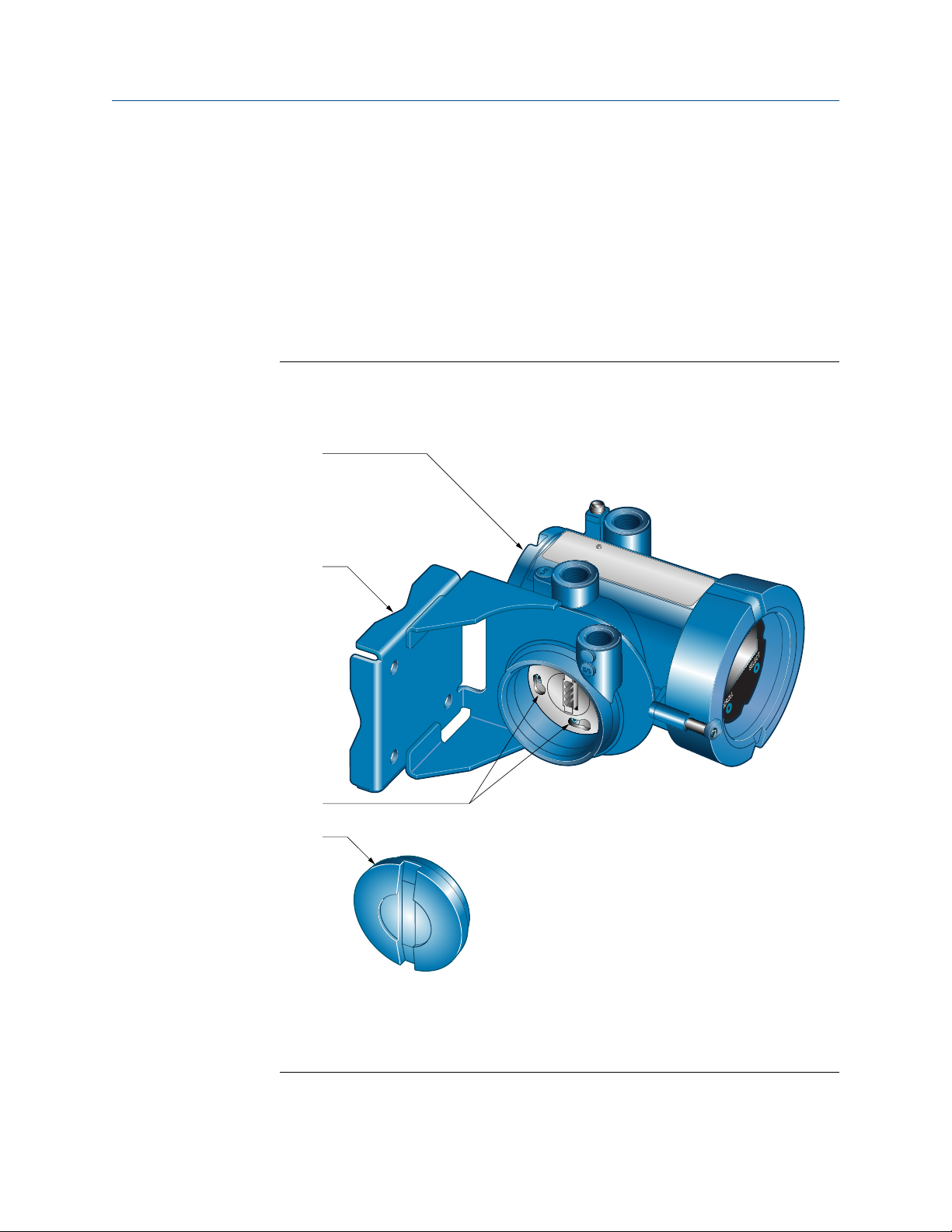
Mounting and sensor wiring for integral installations
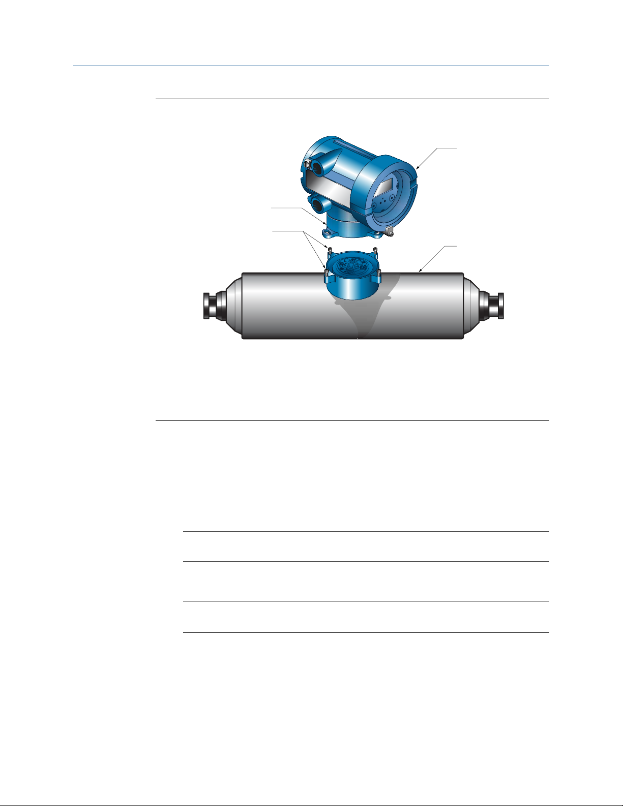
Components of an integral transmitterFigure 2-1:
A. Transmitter
B. Transition ring
C. Cap screws
D. Sensor
Procedure
1. Loosen each of the four cap screws (4 mm) that fasten the transmitter to the base.
2. Rotate the transmitter counter-clockwise so that the cap screws are in the unlocked
position.
3. Gently lift the transmitter straight up, disengaging it from the cap screws.
Important
Do not disconnect or damage the wires that connect the transmitter to the core processor.
4. Rotate the transmitter to the desired orientation.
Important
Do not pinch or stress the wires.
The slots on the transition ring should be aligned with the cap screws.
5. Gently lower the transmitter onto the base, inserting the cap screws into the slots.
6. Rotate the transmitter clockwise so that the cap screws are in the locked position.
7. Tighten the cap screws, torquing to 2.3 to 3.4 N-m.
12 Micro Motion® Model 1700 and 2700
Page 17
A
B
C
G
E
F
D
Mounting and sensor wiring for integral installations
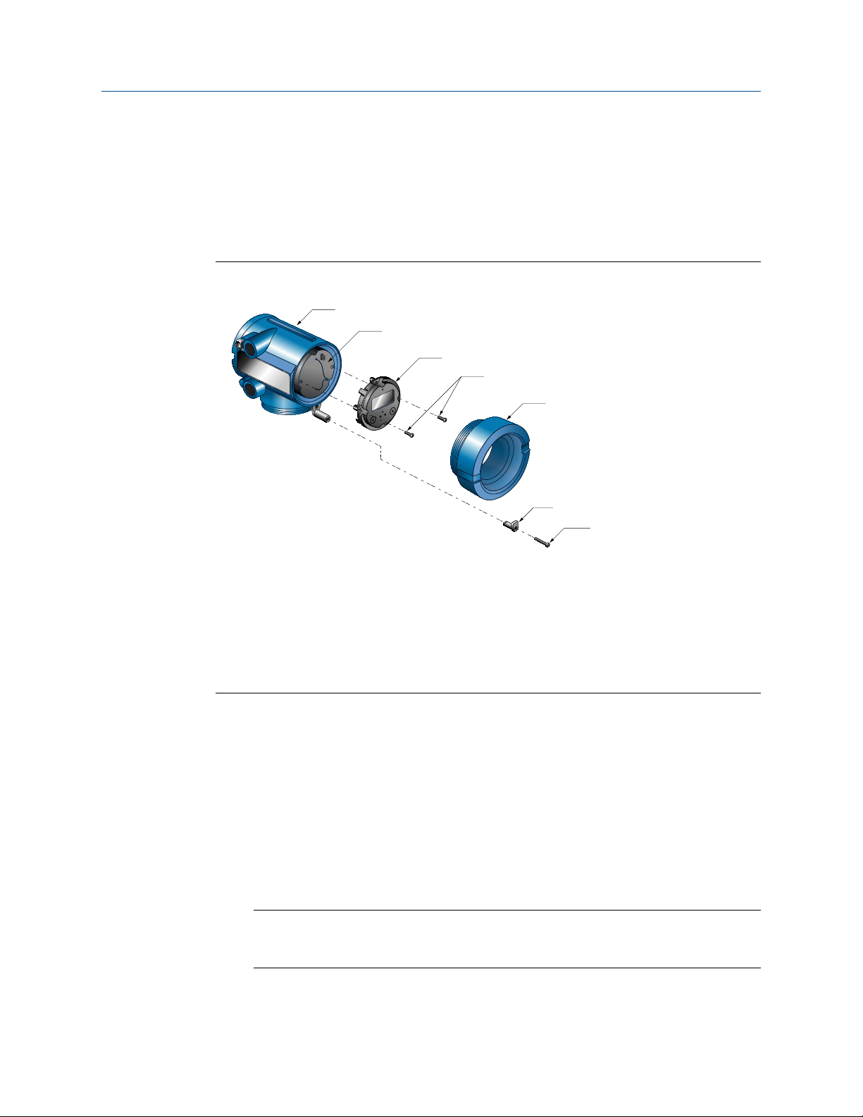
2.3 Rotate the user interface on the transmitter (optional)
The user interface on the transmitter electronics module can be rotated 90º or 180° from
the original position.
Display componentsFigure 2-2:
A. Transmitter housing
B. Sub-bezel
C. Display module
D. Display screws
E. End-cap clamp
F. Cap screw
G. Display cover
Notes
• When using the touch buttons, you must cover at least an 8 mm diameter circle over the
surface above the touch button: using your thumb may be more effective because it has a
greater surface area.
• When the housing cover is removed, the touch buttons do not function.
Procedure
1. Shut off power to the unit.
2. Remove the end-cap clamp by removing the cap screw.
3. Turn the display cover counterclockwise to remove it from the main enclosure.
4. Carefully loosen (and remove if necessary) the semicaptive display screws while
holding the display module in place.
5. Carefully pull the display module out of the main enclosure until the sub-bezel pin
terminals are disengaged from the display module.
Installation Manual 13
Page 18

Mounting and sensor wiring for integral installations
Note
If the display pins come out of the board stack with the display module, remove the pins and
reinstall them.
6. Rotate the display module to the desired position.
7. Insert the sub-bezel pin terminals into the display module pin holes to secure the
display in its new position.
8. If you have removed the display screws, line them up with the matching holes on the
sub-bezel, then reinsert and tighten them.
9. Place the display cover onto the main enclosure.
10. Turn the display cover clockwise until it is snug.
11. Replace the end-cap clamp by reinserting and tightening the cap screw.
12. Restore power to the transmitter.
2.4 Ground the meter components
In an integral installation, all components are grounded together.
Prerequisites
If national standards are not in effect, adhere to the following guidelines for grounding:
• Use copper wire, 14 AWG (2.5 mm2) or larger wire size.
• Keep all ground leads as short as possible, less than 1 Ω impedance.
• Connect ground leads directly to earth, or follow plant standards.
Procedure
Ground via the piping, if possible (see sensor documentation). If grounding via the piping
is not possible, ground according to applicable local standards using the transmitter’s
internal or external ground screw.
14 Micro Motion® Model 1700 and 2700
Page 19
Mounting and sensor wiring for integral installations
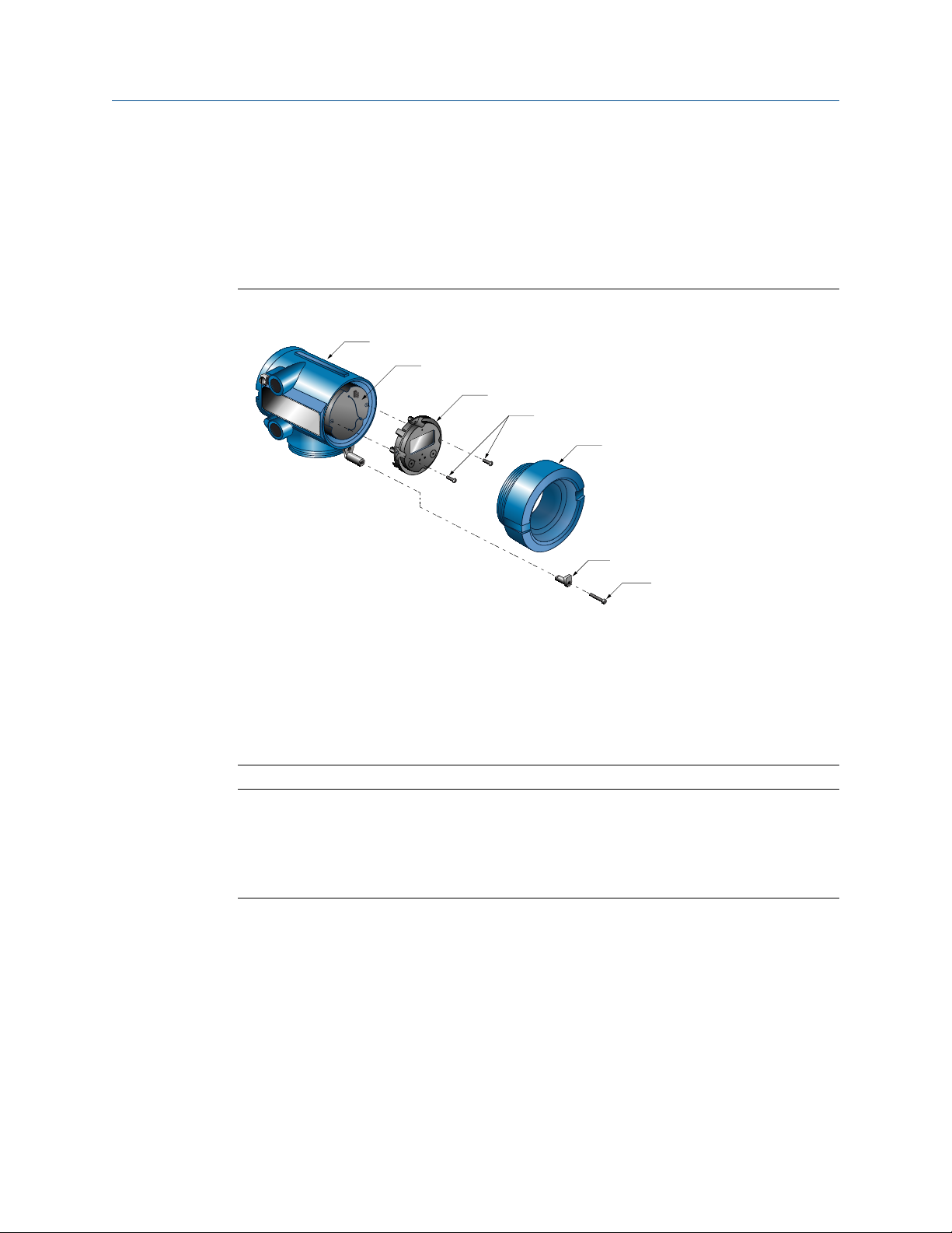
Transmitter internal grounding screwFigure 2-3:
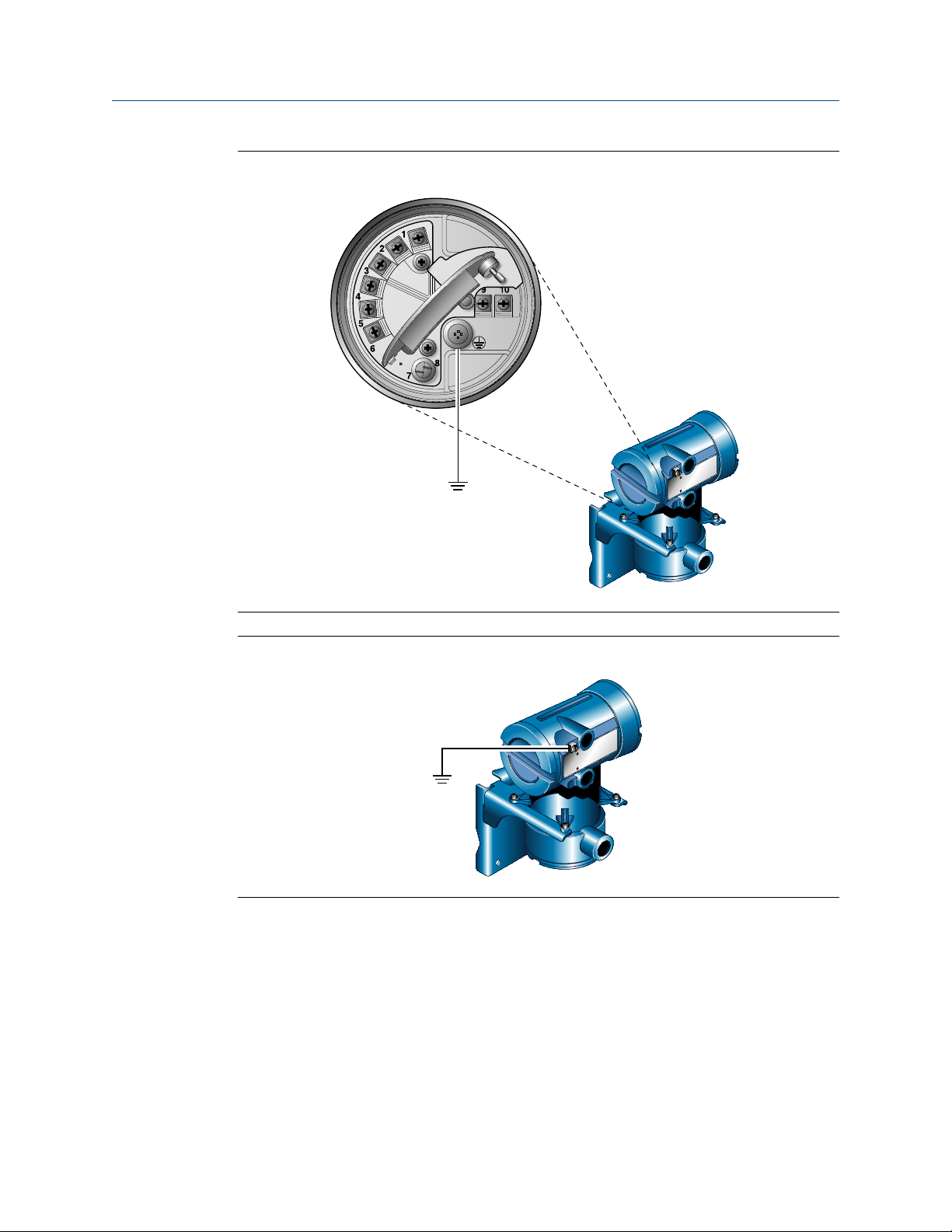
Transmitter external grounding screwFigure 2-4:
Installation Manual 15
Page 20

Mounting and sensor wiring for 4-wire remote installations
3 Mounting and sensor wiring for 4-
wire remote installations
Topics covered in this chapter:
• Mounting options
• Prepare the 4-wire cable
• Wire the transmitter to the sensor
• Rotate the user interface on the transmitter (optional)
• Ground the meter components
3.1 Mounting options
There are two options available for mounting the transmitter:
• Mount the transmitter to a wall or flat surface.
• Mount the transmitter to an instrument pole.
3.1.1 Mount the transmitter to a wall
Prerequisites
• Micro Motion recommends the use of 5/16-18 (8 mm–1.25) fasteners that can
withstand the process environment. Micro Motion does not supply bolts or nuts as
part of the standard offering (general purpose bolts and nuts are available as an
option).
• Ensure that the surface is flat and rigid, does not vibrate, or move excessively.
• Confirm that you have the necessary tools, and the mounting kit shipped with the
transmitter.
Procedure
1. If desired, re-orient the transmitter on the mounting bracket.
a. Remove the junction end-cap from the junction housing.
b. Loosen each of the four cap screws (4 mm).
c. Rotate the bracket so that the transmitter is oriented as desired.
d. Tighten the cap screws, torquing to 30 to 38 in-lbs (3 to 4 N-m).
e. Replace the junction end-cap.
16 Micro Motion® Model 1700 and 2700
Page 21
B
D
C
A
Mounting and sensor wiring for 4-wire remote installations
Figure 3-1:
Components of 4-wire remote mount transmitter (aluminum
housing)
A. Transmitter
B. Mounting bracket
C. Cap screws
D. End-cap
Installation Manual 17
Page 22
B
D
C
A
Mounting and sensor wiring for 4-wire remote installations
Figure 3-2:
Components of a 4-wire remote mount transmitter (stainless steel
housing)
A. Transmitter
B. Mounting bracket
C. Cap screws
D. End-cap
2. Attach the mounting bracket to the wall.
3.1.2 Mount the transmitter to an instrument pole
Prerequisites
• Use two 5/16-inch U-bolts for 2-inch pipe, and four matching nuts, that can
withstand the process environment. Micro Motion does not supply U-bolts or nuts
(appropriate bolts and nuts are available as an option).
• Ensure the instrument pole extends at least 12 inches (305 mm) from a rigid base,
and is no more than 2 inches (50.8 mm) in diameter.
18 Micro Motion® Model 1700 and 2700
Page 23
B
D
C
A
Mounting and sensor wiring for 4-wire remote installations
Procedure
1. If desired, re-orient the transmitter on the mounting bracket.
a. Remove the junction end-cap from the junction housing.
b. Loosen each of the four cap screws (4 mm).
c. Rotate the bracket so that the transmitter is oriented as desired.
d. Tighten the cap screws, torquing to 30 to 38 in-lbs (3 to 4 N-m).
e. Replace the junction end-cap.
Figure 3-3:
Components of 4-wire remote mount transmitter (aluminum
housing)
A. Transmitter
B. Mounting bracket
C. Cap screws
D. End-cap
Installation Manual 19
Page 24

B
D
C
A
Mounting and sensor wiring for 4-wire remote installations
Figure 3-4:
Components of a 4-wire remote mount transmitter (stainless steel
housing)
A. Transmitter
B. Mounting bracket
C. Cap screws
D. End-cap
2. Attach the mounting bracket to an instrument pole.
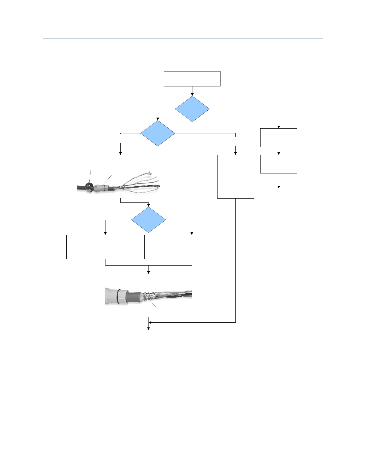
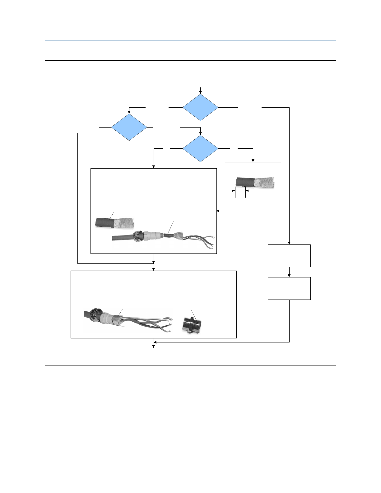
3.2 Prepare the 4-wire cable
Important
For user-supplied cable glands, the gland must be capable of terminating the drain wires.
Note
If you are installing unshielded cable in continuous metallic conduit with 360º termination shielding,
you only need to prepare the cable – you do not need to perform the shielding procedure.
20 Micro Motion® Model 1700 and 2700
Page 25
Mounting and sensor wiring for 4-wire remote installations
4-wire cable preparationFigure 3-5:
Remove the core processor
cover
Cable glands
Micro Motion
cable gland
Pass the wires through the gland nut and clamping insert.
Gland nut
1. Strip 4-1/2 inch (115 mm) of cable jacket.
2. Remove the clear wrap and filler material.
3. Strip all but 3/4 inch (19 mm) of shielding.
Clamping
insert
NPT
Wrap the drain wires twice around the shield and cut off
Gland supplier
Gland type
the excess drain wires.
Cable layout
through the gland.
Terminate the drain
wires inside the
M20
1. Strip 4-1/4 inch (108 mm) of cable jacket.
2. Remove the clear wrap and filler material.
3. Strip all but 1/2 inch (12 mm) of shielding.
User-supplied
cable gland
Pass the wires
gland.
Metal conduit
Run conduit to
sensor
Lay cable in conduit
Done
(do not perform the
shielding procedure)
Drain wires
wrapped around
shield
Go to the shielding
procedure
Installation Manual 21
Page 26
Mounting and sensor wiring for 4-wire remote installations
4-wire cable shieldingFigure 3-6:
From the preparation
procedure
Micro Motion
cable gland
Braided
(armored cable)
Apply the Heat Shrink
1. Slide the shielded heat shrink over the drain wires. Ensure that the
wires are completely covered.
2. Apply heat (250 °F or 120 °C) to shrink the tubing. Do not burn the
cable.
3. Position the clamping insert so the interior end is flush with the braid
of the heat shrink.
Assemble the Gland
1. Fold the shield or braid back over the clamping insert and 1/8 inch
(3 mm) past the O-ring.
2. Install the gland body into the conduit opening on the core processor housing.
3. Insert the wires through gland body and tighten the gland nut onto the gland body.
Cable shield
type
Shielded heat
shrink
Foil
(shielded cable)
NPT
Gland supplier
Gland type M20
After heat applied
User-supplied
cable gland
Trim 7 mm from the shielded
heat shrink
Trim
Terminate the shield
and drain wires in the
Assemble the gland
according to vendor
gland
instructions
Shield folded back
Done
Gland body
3.2.1 4-wire cable types and usage
Micro Motion offers two types of 4-wire cable: shielded and armored. Both types contain
shield drain wires.
The 4-wire cable supplied by Micro Motion consists of one pair of red and black 18 AWG
(0.75 mm2) wires for the VDC connection, and one pair of white and green 22 AWG
(0.35 mm2) wires for the RS-485 connection.
22 Micro Motion® Model 1700 and 2700
Page 27

Mounting and sensor wiring for 4-wire remote installations
User-supplied 4-wire cable must meet the following requirements:
• Twisted pair construction.
• Applicable hazardous area requirements, if the core processor is installed in a
hazardous area.
• Wire gauge appropriate for the cable length between the core processor and the
transmitter.
Wire gaugeTable 3-1:
Wire gauge Maximum cable length
VDC 22 AWG (0.35 mm2) 300 ft (90 m)
VDC 20 AWG (0.5 mm2) 500 ft (150 m)
VDC 18 AWG (0.8 mm2) 1000 ft (300 m)
RS-485 22 AWG (0.35 mm2) or larger 1000 ft (300 m)
3.3 Wire the transmitter to the sensor
1. Connect the cable to the sensor-mounted core processor as described in the sensor
documentation.
2. Feed the wires from the sensor through the conduit opening on the transmitter.
3. Connect wires to the appropriate terminals on the mating connector.
Tip
You may find it easier to unplug the mating connector to connect the wires. If you do so,
remember to firmly reseat the mating connector and tighten the mating connector screws so
that the mating connector cannot accidentally come loose.
Installation Manual 23
Page 28
Mounting and sensor wiring for 4-wire remote installations
Wiring path for transmitters with aluminum housingFigure 3-7:
A. 4-wire cable
B. Transmitter conduit opening
C. Mating connector
A
B
C
VDC+
VDC –
RS-485A
RS-485B
Wiring path for transmitters with stainless steel housingFigure 3-8:
A. 4-wire cable
B. Transmitter conduit opening
C. Mating connector
A
B
C
VDC+
VDC –
RS-485A
RS-485B
24 Micro Motion® Model 1700 and 2700
Page 29
A
B
C
G
E
F
D
Mounting and sensor wiring for 4-wire remote installations
3.4 Rotate the user interface on the transmitter (optional)
The user interface on the transmitter electronics module can be rotated 90º or 180° from
the original position.
Display componentsFigure 3-9:
A. Transmitter housing
B. Sub-bezel
C. Display module
D. Display screws
E. End-cap clamp
F. Cap screw
G. Display cover
Procedure
1. Shut off power to the unit.
2. Remove the end-cap clamp by removing the cap screw.
3. Turn the display cover counterclockwise to remove it from the main enclosure.
4. Carefully loosen (and remove if necessary) the semicaptive display screws while
holding the display module in place.
5. Carefully pull the display module out of the main enclosure until the sub-bezel pin
terminals are disengaged from the display module.
Note
If the display pins come out of the board stack with the display module, remove the pins and
reinstall them.
6. Rotate the display module to the desired position.
Installation Manual 25
Page 30

Mounting and sensor wiring for 4-wire remote installations
7. Insert the sub-bezel pin terminals into the display module pin holes to secure the
display in its new position.
8. If you have removed the display screws, line them up with the matching holes on the
sub-bezel, then reinsert and tighten them.
9. Place the display cover onto the main enclosure.
10. Turn the display cover clockwise until it is snug.
11. Replace the end-cap clamp by reinserting and tightening the cap screw.
12. Restore power to the transmitter.
3.5 Ground the meter components
In 4-wire remote installations, the transmitter and sensor are grounded separately.
Prerequisites
CAUTION!
Improper grounding could cause inaccurate measurements or meter failure.
Note
For hazardous area installations in Europe, refer to standard EN 60079-14 or national standards.
If national standards are not in effect, adhere to the following guidelines for grounding:
• Use copper wire, 14 AWG (2.5 mm2) or larger wire size.
• Keep all ground leads as short as possible, less than 1 Ω impedance.
• Connect ground leads directly to earth, or follow plant standards.
Procedure
1. Ground the sensor according to the instructions in the sensor documentation.
2. Ground the transmitter according to applicable local standards, using the
transmitter’s internal or external ground screw.
26 Micro Motion® Model 1700 and 2700
Page 31

Mounting and sensor wiring for 4-wire remote installations
Transmitter internal grounding screwFigure 3-10:
Transmitter external grounding screwFigure 3-11:
Installation Manual 27
Page 32

Mounting and sensor wiring for 9-wire remote installations
4 Mounting and sensor wiring for 9-
wire remote installations
Topics covered in this chapter:
• Mounting options
• Prepare the 9-wire cable
• Wire the transmitter to the sensor using jacketed cable
• Wire the transmitter to the sensor using shielded or armored cable
• Rotate the user interface on the transmitter (optional)
• Ground the meter components
4.1 Mounting options
There are two options available for mounting the transmitter:
• Mount the transmitter to a wall or flat surface.
• Mount the transmitter to an instrument pole.
4.1.1 Mount the transmitter to a wall
Prerequisites
• Micro Motion recommends the use of 5/16-18 (8 mm–1.25) fasteners that can
withstand the process environment. Micro Motion does not supply bolts or nuts as
part of the standard offering (general purpose bolts and nuts are available as an
option).
• Ensure that the surface is flat and rigid, does not vibrate, or move excessively.
• Confirm that you have the necessary tools, and the mounting kit shipped with the
transmitter.
Procedure
1. If desired, re-orient the transmitter on the mounting bracket.
a. Loosen each of the four cap screws (4 mm).
b. Rotate the bracket so that the transmitter is oriented as desired.
c. Tighten the cap screws, torquing to 30 to 38 in-lbs (3 to 4 N-m).
28 Micro Motion® Model 1700 and 2700
Page 33

A
B
C
Mounting and sensor wiring for 9-wire remote installations
Components of 9-wire remote mount transmitterFigure 4-1:
A. Transmitter
B. Cap screws
C. Mounting bracket
2. Attach the mounting bracket to the wall.
4.1.2 Mount the transmitter to an instrument pole
Prerequisites
• Use two 5/16-inch U-bolts for 2-inch pipe, and four matching nuts, that can
withstand the process environment. Micro Motion does not supply U-bolts or nuts
(appropriate bolts and nuts are available as an option).
• Ensure the instrument pole extends at least 12 inches (305 mm) from a rigid base,
and is no more than 2 inches (50.8 mm) in diameter.
Procedure
1. If desired, re-orient the transmitter on the mounting bracket.
a. Loosen each of the four cap screws (4 mm).
b. Rotate the bracket so that the transmitter is oriented as desired.
c. Tighten the cap screws, torquing to 30 to 38 in-lbs (3 to 4 N-m).
Installation Manual 29
Page 34

A
B
C
Mounting and sensor wiring for 9-wire remote installations
Components of 9-wire remote mount transmitterFigure 4-2:
A. Transmitter
B. Cap screws
C. Mounting bracket
2. Attach the mounting bracket to an instrument pole.
4.2 Prepare the 9-wire cable
Micro Motion supplies three types of 9-wire cable: jacketed, shielded, and armored. The
type of cable you are using determines how you will prepare the cable.
Perform the cable preparation procedure appropriate for your cable type.
30 Micro Motion® Model 1700 and 2700
Page 35

Mounting and sensor wiring for 9-wire remote installations
Preparing jacketed cableFigure 4-3:
Prepare jacketed
cable at the sensor
end
1. Trim 4 ½ inches (115 mm) of cable jacket.
2. Remove the clear wrap and filler material.
3. Remove the foil that is around the insulated wires
and separate them.
Trim cable jacket
4. Identify the drain wires in the cable. Clip off each
drain wire as close as possible to the cable jacket.
Drain wires clipped
5. Slide the 1 ½ inch (40 mm) heat-shrink tubing over
the wires and cable jacket. The tubing should
completely cover the clipped ends of the drain wires.
Prepare jacketed
cable at the
transmitter end
1. Trim 4 inches (100 mm) of cable jacket.
2. Remove the clear wrap and filler material.
3. Remove the foil that is around the insulated wires
and separate them.
Trim cable jacket
4. Identify the drain wires in the cable and bring them
together. Fan the other wires to the outside of the
cable. Twist the drain wires together.
5. Slide the 3-inch (75 mm) heat-shrink tubing over
the drain wires. Push the tubing as close as possible
to the cable jacket.
6. Slide the 1 ½ inch (40 mm) long heat-shrink tubing
over the cable jacket. The tubing should
completely cover all portions of the drain wires that
remain exposed next to the cable jacket.
Heat-shrink
tubing
6. Without burning the cable, apply heat to shrink all
tubing. Recommended temperature is 250 °F (121
°C).
7. Allow the cable to cool, then strip ¼ inch (5 mm) of
insulation from each wire.
Heat-shrink tubing over
cable jacket
Heat-shrink tubing over drain
wires
7. Without burning the cable, apply heat to shrink all
tubing. Recommended temperature is 250 °F (121
°C).
8. Allow the cable to cool, then strip ¼ inch (5 mm) of
insulation from each wire.
Installation Manual 31
Page 36

Mounting and sensor wiring for 9-wire remote installations
Preparing shielded or armored cableFigure 4-4:
Prepare shielded or
armored cable at the
sensor end
1. Without cutting the shield, strip 7 inches (175 mm)
of outer jacket.
2. Strip 6 ½ inches (165 mm) of braided shield, so ½
inch (10 mm) of shield remains exposed.
3. Remove the foil shield that is between the braided
shield and inner jacket.
4. Strip 4 ½ inches (115 mm) of inner jacket.
Trim outer jacket
Trim braided shield
Trim inner jacket
5. Remove the clear wrap and filler material.
6. Remove the foil that is around the insulated wires
and separate them.
7. Identify the drain wires in the cable. Clip each drain
wire as close as possible to the cable jacket.
Drain wires clipped
8. Slide the 1 ½ inch (40 mm) long heat-shrink tubing
over the cable jacket. The tubing should completely
cover the clipped ends of the drain wires.
Prepare shielded or
armored cable at the
transmitter end
1. Without cutting the shield, strip 9 inches (225 mm) of
cable jacket.
2. Strip 8 ½ inches (215 mm) of braided shield, so ½
inch (10 mm) of shield remains exposed.
3. Remove the foil shield that is between the braided
shield and inner jacket.
4. Strip 4 inches (100 mm) of inner jacket.
Trim outer jacket
Trim braided shield
Trim inner jacket
5. Remove the clear wrap and filler material.
6. Remove the foil that is around the insulated wires and
separate them.
7. Identify the drain wires in the cable and bring them
together. Fan the other wires to the outside of the
cable. Twist the drain wires together.
8. Slide the 3-inch (75 mm) long heat-shrink tubing over
the drain wires. Push the tubing as close as possible to
the inner jacket.
9. Slide the 1 ½ inch (40 mm) long heat-shrink tubing
over the cable jacket. The tubing should completely
cover all portions of the drain wires that remain
exposed next to the cable jacket.
Heat-shrink tubing
9. Without burning the cable, apply heat to shrink all
tubing. Recommended temperature is 250 °F (121
°C).
10. Allow the cable to cool, then strip ¼ inch (5 mm) of
insulation from each wire.
Heat-shrink tubing over cable
Heat-shrink tubing over drain wires
10. Without burning the cable, apply heat to shrink all
tubing. Recommended temperature is 250 °F (121
°C).
11. Allow the cable to cool, then strip ¼ inch (5 mm) of
insulation from each wire.
jacket
32 Micro Motion® Model 1700 and 2700
Page 37

Mounting and sensor wiring for 9-wire remote installations
4.2.1 Micro Motion 9-wire cable types and usage
Cable types
Micro Motion supplies three types of 9-wire cable: jacketed, shielded, and armored. Note
the following differences between the cable types:
• Armored cable provides mechanical protection for the cable wires.
• Jacketed cable has a smaller bend radius than shielded or armored cable.
• If ATEX compliance is required, the different cable types have different installation
requirements.
Cable jacket types
All cable types can be ordered with a PVC jacket or Teflon® FEP jacket. Teflon FEP is
required for the following installation types:
• All installations that include a T-series sensor.
• All installations with a cable length of 250 ft (75 m) or greater, a nominal flow less
than 20 percent, and ambient temperature changes greater than +68 °F (+20 °C).
Cable jacket material and temperature rangesTable 4-1:
Handling temperature Operating temperature
Cable jacket material Low limit High limit Low limit High limit
PVC –4 °F (–20 °C) +194 °F (+90 °C) –40 °F (–40 °C) +221 °F (+105 °C)
Teflon FEP –40 °F (–40 °C) +194 °F (+90 °C) –76 °F (–60 °C) +302 °F (+150 °C)
Cable bend radii
Bend radii of jacketed cableTable 4-2:
Jacket material Outside diameter Minimum bend radii
Static (no load) condition Under dynamic load
PVC 0.415 inches (10 mm) 3–1/8 inches (80 mm) 6–1/4 inches (159 mm)
Teflon FEP 0.340 inches (9 mm) 2–5/8 inches (67 mm) 5–1/8 inches (131 mm)
Bend radii of shielded cableTable 4-3:
Jacket material Outside diameter Minimum bend radii
Static (no load) condition Under dynamic load
PVC 0.2 inches (14 mm) 4–1/4 inches (108 mm) 8–1/2 inches (216 mm)
Teflon FEP 0.425 inches (11 mm) 3–1/4 inches (83 mm) 6–3/8 inches (162 mm)
Installation Manual 33
Page 38

A
C (4)
B (4)
D (5)
Mounting and sensor wiring for 9-wire remote installations
Bend radii of armored cableTable 4-4:
Jacket material Outside diameter Minimum bend radii
PVC 0.525 inches (14 mm) 4–1/4 inches (108 mm) 8–1/2 inches (216 mm)
Teflon FEP 0.340 inches (9 mm) 3–1/4 inches (83 mm) 6–3/8 inches (162 mm)
Cable illustrations
Cross-section view of jacketed cableFigure 4-5:
Static (no load) condition Under dynamic load
A. Outer jacket
B. Drain wire (4 total)
C. Foil shield (4 total)
D. Filler (5 total)
34 Micro Motion® Model 1700 and 2700
Page 39

Cross-section view of shielded cableFigure 4-6:
A
C (1)
B
D
E (4)
F (4)
G (5)
A
C (1)
B
D
E (4)
F (4)
G (5)
A. Outer jacket
B. Tin-plated copper braided shield
C. Foil shield (1 total)
D. Inner jacket
E. Drain wire (4 total)
F. Foil shield (4 total)
G. Filler (5 total)
Mounting and sensor wiring for 9-wire remote installations
Cross-section view of armored cableFigure 4-7:
A. Outer jacket
B. Stainless steel braided shield
C. Foil shield (1 total)
D. Inner jacket
E. Drain wire (4 total)
F. Foil shield (4 total)
G. Filler (5 total)
Installation Manual 35
Page 40

Mounting and sensor wiring for 9-wire remote installations
4.3 Wire the transmitter to the sensor using jacketed cable
Prerequisites
For ATEX installations, the jacketed cable must be installed inside a user-supplied sealed
metallic conduit that provides 360° termination shielding for the enclosed cable.
CAUTION!
Sensor wiring is intrinsically safe. To keep sensor wiring intrinsically safe, keep the sensor
wiring separated from power supply wiring and output wiring.
CAUTION!
Keep cable away from devices such as transformers, motors, and power lines, which produce
large magnetic fields. Improper installation of cable, cable gland, or conduit could cause
inaccurate measurements or flow meter failure.
CAUTION!
Improperly sealed housings can expose electronics to moisture, which can cause measurement
error or flowmeter failure. Install drip legs in conduit and cable, if necessary. Inspect and
grease all gaskets and O-rings. Fully close and tighten all housing covers and conduit openings.
Procedure
1. Run the cable through the conduit. Do not install 9-wire cable and power cable in
the same conduit.
2. To prevent conduit connectors from seizing in the threads of the conduit openings,
apply a conductive anti-galling compound to the threads, or wrap threads with PTFE
tape two to three layers deep.
Wrap the tape in the opposite direction that the male threads will turn when
inserted into the female conduit opening.
3. Remove the junction box cover and core processor end-cap.
4. At both the sensor and transmitter, do the following:
a. Connect a male conduit connector and waterproof seal to the conduit opening
for 9-wire.
b. Pass the cable through the conduit opening for the 9-wire cable.
c. Insert the stripped end of each wire into the corresponding terminal at the
sensor and transmitter ends, matching by color (see Table 4-5). No bare wires
should remain exposed.
Note
For ELITE®, H-Series, T-Series, and some F-Series sensors, match the wire to the terminal
by the color identified on the inside of the sensor junction box cover.
36 Micro Motion® Model 1700 and 2700
Page 41

D
I
H
F
E
A
B
C
G
Mounting and sensor wiring for 9-wire remote installations
Sensor and transmitter terminal designationsTable 4-5:
Wire color Sensor terminal Transmitter terminal Function
Black No connection 0 Drain wires
Brown 1 1 Drive +
Red 2 2 Drive –
Orange 3 3 Temperature –
Yellow 4 4 Temperature return
Green 5 5 Left pickoff +
Blue 6 6 Right pickoff +
Violet 7 7 Temperature +
Gray 8 8 Right pickoff –
White 9 9 Left pickoff –
d. Tighten the screws to hold the wire in place.
e. Ensure integrity of gaskets, grease all O-rings, then replace the junction box and
transmitter housing covers and tighten all screws, as required.
4.3.1 Sensor and transmitter terminals
Figure 4-8:
A. Violet
B. Yellow
C. Orange
D. Brown
E. White
F. Green
G. Red
H. Gray
I. Blue
All ELITE, H-Series, and T-Series sensor, and 2005 or newer F-Series sensor
terminals
Installation Manual 37
Page 42

1
9
8
7
6
5
4
3
2
A
Mounting and sensor wiring for 9-wire remote installations
All Model D and Model DL, and pre-2005 F-Series sensor terminalsFigure 4-9:
Figure 4-10:
Model DT sensor terminals (user-supplied metal junction box with
terminal block)
A. Earth ground
38 Micro Motion® Model 1700 and 2700
Page 43

Transmitter terminalsFigure 4-11:
A
B
I
H
G
F
E
D
C
J
A. Brown
B. Violet
C. Yellow
D. Orange
E. Gray
F. Blue
G. White
H. Green
I. Red
J. Ground screw (black)
Mounting and sensor wiring for 9-wire remote installations
4.4 Wire the transmitter to the sensor using shielded or armored cable
Prerequisites
For ATEX installations, shielded or armored cable must be installed with cable glands, at
both the sensor and transmitter ends. Cable glands that meet ATEX requirements can be
purchased from Micro Motion. Cable glands from other vendors can be used.
CAUTION!
Keep cable away from devices such as transformers, motors, and power lines, which produce
large magnetic fields. Improper installation of cable, cable gland, or conduit could cause
inaccurate measurements or flow meter failure.
CAUTION!
Install cable glands in the 9-wire conduit opening in the transmitter housing and the sensor
junction box. Ensure that the cable drain wires and shields do not make contact with the
junction box or the transmitter housing. Improper installation of cable or cable glands could
cause inaccurate measurements or flow meter failure.
Installation Manual 39
Page 44

A B C D E F
G H I
Mounting and sensor wiring for 9-wire remote installations
CAUTION!
Improperly sealed housings can expose electronics to moisture, which can cause measurement
error or flowmeter failure. Install drip legs in conduit and cable, if necessary. Inspect and
grease all gaskets and O-rings. Fully close and tighten all housing covers and conduit openings.
Procedure
1. Identify the components of the cable gland and cable (see Figure 4-12).
Cable gland and cable (exploded view)Figure 4-12:
A. Cable
B. Sealing nut
C. Compression nut
D. Brass compression ring
E. Braided shield
F. Cable
G. Tape or heat-shrink tubing
H. Clamp seat (shown as integral to nipple)
I. Nipple
2. Unscrew the nipple from the compression nut.
3. Screw the nipple into the conduit opening for the 9-wire cable. Tighten it to one turn
4. Slide the compression ring, compression nut, and sealing nut onto the cable. Make
5. Pass the cable end through the nipple so the braided shield slides over the tapered
6. Slide the compression ring over the braided shield.
7. Screw the compression nut onto the nipple. Tighten the sealing nut and
8. Use a 25-mm (1-inch) wrench to tighten the sealing nut and compression nut to
40 Micro Motion® Model 1700 and 2700
past hand-tight.
sure the compression ring is oriented so the taper will mate properly with the
tapered end of the nipple.
end of the nipple.
compression nut by hand to ensure that the compression ring traps the braided
shield.
20–25 foot-pounds (27–34 N-m) of torque. See Figure 4-13 for an illustration of a
complete cable gland assembly.
Page 45

Cross-section of assembled cable gland with cableFigure 4-13:
A
B
C
E
D
F
G A
A. Cable
B. Sealing nut
C. Seal
D. Compression nut
E. Braided shield
F. Brass compression ring
G. Nipple
Mounting and sensor wiring for 9-wire remote installations
9. Remove the junction box cover and core processor end-cap.
10. At both the sensor and transmitter, connect the cable according to the following
procedure:
a. Insert the stripped end of each wire into the corresponding terminal at the
sensor and transmitter ends, matching by color (see Table 4-6). No bare wires
should remain exposed.
Note
For ELITE®, H-Series, T-Series, and some F-Series sensors, match the wire to the terminal
by the color identified on the inside of the sensor junction box cover.
Sensor and transmitter terminal designationsTable 4-6:
Wire color Sensor terminal Transmitter terminal Function
Black No connection 0 Drain wires
Brown 1 1 Drive +
Red 2 2 Drive –
Orange 3 3 Temperature –
Yellow 4 4 Temperature return
Green 5 5 Left pickoff +
Blue 6 6 Right pickoff +
Violet 7 7 Temperature +
Gray 8 8 Right pickoff –
Installation Manual 41
Page 46

D
I
H
F
E
A
B
C
G
Mounting and sensor wiring for 9-wire remote installations
Sensor and transmitter terminal designations (continued)Table 4-6:
Wire color Sensor terminal Transmitter terminal Function
White 9 9 Left pickoff –
b. Tighten the screws to hold the wires in place.
c. Ensure integrity of gaskets, grease all O-rings, then replace the junction box and
transmitter housing covers and tighten all screws, as required.
4.4.1 Sensor and transmitter terminals
Figure 4-14:
A. Violet
B. Yellow
C. Orange
D. Brown
E. White
F. Green
G. Red
H. Gray
I. Blue
All ELITE, H-Series, and T-Series sensor, and 2005 or newer F-Series
sensor terminals
42 Micro Motion® Model 1700 and 2700
Page 47

1
9
8
7
6
5
4
3
2
A
Mounting and sensor wiring for 9-wire remote installations
All Model D and Model DL, and pre-2005 F-Series sensor terminalsFigure 4-15:
Figure 4-16:
Model DT sensor terminals (user-supplied metal junction box with
terminal block)
A. Earth ground
Installation Manual 43
Page 48

A
B
I
H
G
F
E
D
C
J
Mounting and sensor wiring for 9-wire remote installations
Transmitter terminalsFigure 4-17:
A. Brown
B. Violet
C. Yellow
D. Orange
E. Gray
F. Blue
G. White
H. Green
I. Red
J. Ground screw (black)
4.5 Rotate the user interface on the transmitter (optional)
The user interface on the transmitter electronics module can be rotated 90º or 180° from
the original position.
44 Micro Motion® Model 1700 and 2700
Page 49

Display componentsFigure 4-18:
A
B
C
G
E
F
D
A. Transmitter housing
B. Sub-bezel
C. Display module
D. Display screws
E. End-cap clamp
F. Cap screw
G. Display cover
Mounting and sensor wiring for 9-wire remote installations
Procedure
1. Shut off power to the unit.
2. Remove the end-cap clamp by removing the cap screw.
3. Turn the display cover counterclockwise to remove it from the main enclosure.
4. Carefully loosen (and remove if necessary) the semicaptive display screws while
holding the display module in place.
5. Carefully pull the display module out of the main enclosure until the sub-bezel pin
terminals are disengaged from the display module.
Note
If the display pins come out of the board stack with the display module, remove the pins and
reinstall them.
6. Rotate the display module to the desired position.
7. Insert the sub-bezel pin terminals into the display module pin holes to secure the
display in its new position.
8. If you have removed the display screws, line them up with the matching holes on the
sub-bezel, then reinsert and tighten them.
9. Place the display cover onto the main enclosure.
10. Turn the display cover clockwise until it is snug.
Installation Manual 45
Page 50

Mounting and sensor wiring for 9-wire remote installations
11. Replace the end-cap clamp by reinserting and tightening the cap screw.
12. Restore power to the transmitter.
4.6 Ground the meter components
In 9-wire remote installations, the transmitter/core processor assembly and sensor are
grounded separately.
Prerequisites
CAUTION!
Improper grounding could cause inaccurate measurements or meter failure.
Note
For hazardous area installations in Europe, refer to standard EN 60079-14 or national standards.
If national standards are not in effect, adhere to the following guidelines for grounding:
• Use copper wire, 14 AWG (2.5 mm2) or larger wire size.
• Keep all ground leads as short as possible, less than 1 Ω impedance.
• Connect ground leads directly to earth, or follow plant standards.
Procedure
1. Ground the sensor according to the instructions in the sensor documentation.
2. Ground the transmitter/core processor assembly according to applicable local
standards, using the transmitter’s internal ground screw or the transmitter's
external ground screw.
46 Micro Motion® Model 1700 and 2700
Page 51

Mounting and sensor wiring for 9-wire remote installations
Transmitter internal ground screwFigure 4-19:
Transmitter external ground screwFigure 4-20:
Installation Manual 47
Page 52

Mounting and sensor wiring for remote core processor with remote sensor installations
5 Mounting and sensor wiring for
remote core processor with remote
sensor installations
Topics covered in this chapter:
• Mounting options
• Mount the remote core processor
• Prepare the 4-wire cable
• Wire the transmitter to the remote core processor
• Prepare the 9-wire cable
• Wire the remote core processor to the sensor using jacketed cable
• Wire the remote core processor to the sensor using shielded or armored cable
• Rotate the user interface on the transmitter (optional)
• Ground the meter components
5.1 Mounting options
There are two options available for mounting the transmitter:
• Mount the transmitter to a wall or flat surface.
• Mount the transmitter to an instrument pole.
5.1.1 Mount the transmitter to a wall
Prerequisites
• Micro Motion recommends the use of 5/16-18 (8 mm–1.25) fasteners that can
withstand the process environment. Micro Motion does not supply bolts or nuts as
part of the standard offering (general purpose bolts and nuts are available as an
option).
• Ensure that the surface is flat and rigid, does not vibrate, or move excessively.
• Confirm that you have the necessary tools, and the mounting kit shipped with the
transmitter.
Procedure
1. If desired, re-orient the transmitter on the mounting bracket.
a. Remove the junction end-cap from the junction housing.
48 Micro Motion® Model 1700 and 2700
Page 53

B
D
C
A
Mounting and sensor wiring for remote core processor with remote sensor installations
b. Loosen each of the four cap screws (4 mm).
c. Rotate the bracket so that the transmitter is oriented as desired.
d. Tighten the cap screws, torquing to 30 to 38 in-lbs (3 to 4 N-m).
e. Replace the junction end-cap.
Figure 5-1:
Components of 4-wire remote mount transmitter (aluminum
housing)
A. Transmitter
B. Mounting bracket
C. Cap screws
D. End-cap
Installation Manual 49
Page 54

B
D
C
A
Mounting and sensor wiring for remote core processor with remote sensor installations
Figure 5-2:
Components of a 4-wire remote mount transmitter (stainless steel
housing)
A. Transmitter
B. Mounting bracket
C. Cap screws
D. End-cap
2. Attach the mounting bracket to the wall.
5.1.2 Mount the transmitter to an instrument pole
Prerequisites
• Use two 5/16-inch U-bolts for 2-inch pipe, and four matching nuts, that can
withstand the process environment. Micro Motion does not supply U-bolts or nuts
(appropriate bolts and nuts are available as an option).
• Ensure the instrument pole extends at least 12 inches (305 mm) from a rigid base,
and is no more than 2 inches (50.8 mm) in diameter.
50 Micro Motion® Model 1700 and 2700
Page 55

B
D
C
A
Mounting and sensor wiring for remote core processor with remote sensor installations
Procedure
1. If desired, re-orient the transmitter on the mounting bracket.
a. Remove the junction end-cap from the junction housing.
b. Loosen each of the four cap screws (4 mm).
c. Rotate the bracket so that the transmitter is oriented as desired.
d. Tighten the cap screws, torquing to 30 to 38 in-lbs (3 to 4 N-m).
e. Replace the junction end-cap.
Figure 5-3:
Components of 4-wire remote mount transmitter (aluminum
housing)
A. Transmitter
B. Mounting bracket
C. Cap screws
D. End-cap
Installation Manual 51
Page 56

B
D
C
A
Mounting and sensor wiring for remote core processor with remote sensor installations
Figure 5-4:
Components of a 4-wire remote mount transmitter (stainless steel
housing)
A. Transmitter
B. Mounting bracket
C. Cap screws
D. End-cap
2. Attach the mounting bracket to an instrument pole.
5.2 Mount the remote core processor
This procedure is required only for remote core processor with remote transmitter
installations.
Prerequisites
For mounting the remote core processor to a wall:
52 Micro Motion® Model 1700 and 2700
Page 57

A
B
Mounting and sensor wiring for remote core processor with remote sensor installations
• Micro Motion recommends the use of 5/16-18 (8 mm–1.25) fasteners that can
withstand the process environment. Micro Motion does not supply bolts or nuts as
part of the standard offering (general purpose bolts and nuts are available as an
option).
• Ensure that the surface is flat and rigid, does not vibrate, or move excessively.
• Confirm that you have the necessary tools, and the mounting kit shipped with the
transmitter.
For mounting the remote core processor to an instrument pole:
• Use two 5/16-inch U-bolts for 2-inch pipe, and four matching nuts, that can
withstand the process environment. Micro Motion does not supply U-bolts or nuts
(appropriate bolts and nuts are available as an option).
• Ensure the instrument pole extends at least 12 inches (305 mm) from a rigid base,
and is no more than 2 inches (50.8 mm) in diameter.
Procedure
1. If desired, reorient the core processor housing on the bracket.
a. Loosen each of the four cap screws (4 mm).
b. Rotate the bracket so that the core processor is oriented as desired.
c. Tighten the cap screws, torquing to 30 to 38 in-lbs (3 to 4 N-m).
Components of a remote core processorFigure 5-5:
A. Mounting bracket
B. Cap screws
2. Attach the mounting bracket to an instrument pole or wall.
5.3 Prepare the 4-wire cable
Important
For user-supplied cable glands, the gland must be capable of terminating the drain wires.
Installation Manual 53
Page 58

Mounting and sensor wiring for remote core processor with remote sensor installations
Note
If you are installing unshielded cable in continuous metallic conduit with 360º termination shielding,
you only need to prepare the cable – you do not need to perform the shielding procedure.
4-wire cable preparationFigure 5-6:
Remove the core processor
cover
Cable glands
Micro Motion
cable gland
Pass the wires through the gland nut and clamping insert.
Gland nut
1. Strip 4-1/2 inch (115 mm) of cable jacket.
2. Remove the clear wrap and filler material.
3. Strip all but 3/4 inch (19 mm) of shielding.
Clamping
insert
NPT
Wrap the drain wires twice around the shield and cut off
Gland supplier
Gland type
the excess drain wires.
Cable layout
through the gland.
Terminate the drain
wires inside the
M20
1. Strip 4-1/4 inch (108 mm) of cable jacket.
2. Remove the clear wrap and filler material.
3. Strip all but 1/2 inch (12 mm) of shielding.
User-supplied
cable gland
Pass the wires
gland.
Metal conduit
Run conduit to
sensor
Lay cable in conduit
Done
(do not perform the
shielding procedure)
Drain wires
wrapped around
shield
Go to the shielding
procedure
54 Micro Motion® Model 1700 and 2700
Page 59

Mounting and sensor wiring for remote core processor with remote sensor installations
4-wire cable shieldingFigure 5-7:
From the preparation
procedure
Micro Motion
cable gland
Braided
(armored cable)
Apply the Heat Shrink
1. Slide the shielded heat shrink over the drain wires. Ensure that the
wires are completely covered.
2. Apply heat (250 °F or 120 °C) to shrink the tubing. Do not burn the
cable.
3. Position the clamping insert so the interior end is flush with the braid
of the heat shrink.
Assemble the Gland
1. Fold the shield or braid back over the clamping insert and 1/8 inch
(3 mm) past the O-ring.
2. Install the gland body into the conduit opening on the core processor housing.
3. Insert the wires through gland body and tighten the gland nut onto the gland body.
Cable shield
type
Shielded heat
shrink
Foil
(shielded cable)
NPT
Gland supplier
Gland type M20
After heat applied
User-supplied
cable gland
Trim 7 mm from the shielded
heat shrink
Trim
Terminate the shield
and drain wires in the
Assemble the gland
according to vendor
gland
instructions
Shield folded back
Done
Gland body
5.3.1 4-wire cable types and usage
Micro Motion offers two types of 4-wire cable: shielded and armored. Both types contain
shield drain wires.
The 4-wire cable supplied by Micro Motion consists of one pair of red and black 18 AWG
(0.75 mm2) wires for the VDC connection, and one pair of white and green 22 AWG
(0.35 mm2) wires for the RS-485 connection.
Installation Manual 55
Page 60

A
B
C
Mounting and sensor wiring for remote core processor with remote sensor installations
User-supplied 4-wire cable must meet the following requirements:
• Twisted pair construction.
• Applicable hazardous area requirements, if the core processor is installed in a
hazardous area.
• Wire gauge appropriate for the cable length between the core processor and the
transmitter.
Wire gaugeTable 5-1:
Wire gauge Maximum cable length
VDC 22 AWG (0.35 mm2) 300 ft (90 m)
VDC 20 AWG (0.5 mm2) 500 ft (150 m)
VDC 18 AWG (0.8 mm2) 1000 ft (300 m)
RS-485 22 AWG (0.35 mm2) or larger 1000 ft (300 m)
5.4 Wire the transmitter to the remote core processor
1. If you are installing a Micro Motion-supplied cable gland at the core processor
housing, identify the cable gland to use for the 4-wire cable conduit opening.
Cable gland identificationFigure 5-8:
A. Cable gland used with 4-wire conduit opening
B. 3/4"–14 NPT cable gland used with 9-wire conduit opening
C. 1/2"–14 NPT or M20x1.5 cable glands used with transmitter
2. Connect the cable to the core processor as described in the sensor documentation.
56 Micro Motion® Model 1700 and 2700
Page 61

Mounting and sensor wiring for remote core processor with remote sensor installations
3. Feed the wires from the remote core processor through the conduit opening.
4. Connect wires to the appropriate terminals on the mating connector.
Tip
You may find it easier to unplug the mating connector to connect the wires. If you do so,
remember to firmly reseat the mating connector and tighten the mating connector screws so
that the mating connector cannot accidentally come loose.
Wiring path for transmitters with aluminum housingFigure 5-9:
A
B
A. 4-wire cable
B. Transmitter conduit opening
C. Mating connector
C
VDC+
VDC –
RS-485A
RS-485B
Installation Manual 57
Page 62

Mounting and sensor wiring for remote core processor with remote sensor installations
Wiring path for transmitters with stainless steel housingFigure 5-10:
VDC+
VDC –
RS-485A
RS-485B
A
B
C
A. 4-wire cable
B. Transmitter conduit opening
C. Mating connector
5.5 Prepare the 9-wire cable
Micro Motion supplies three types of 9-wire cable: jacketed, shielded, and armored. The
type of cable you are using determines how you will prepare the cable.
Perform the cable preparation procedure appropriate for your cable type.
58 Micro Motion® Model 1700 and 2700
Page 63

Mounting and sensor wiring for remote core processor with remote sensor installations
Preparing jacketed cableFigure 5-11:
Prepare jacketed
cable at the sensor
end
1. Trim 4 ½ inches (115 mm) of cable jacket.
2. Remove the clear wrap and filler material.
3. Remove the foil that is around the insulated wires
and separate them.
Trim cable jacket
4. Identify the drain wires in the cable. Clip off each
drain wire as close as possible to the cable jacket.
Drain wires clipped
5. Slide the 1 ½ inch (40 mm) heat-shrink tubing over
the wires and cable jacket. The tubing should
completely cover the clipped ends of the drain wires.
Prepare jacketed
cable at the
transmitter end
1. Trim 4 inches (100 mm) of cable jacket.
2. Remove the clear wrap and filler material.
3. Remove the foil that is around the insulated wires
and separate them.
Trim cable jacket
4. Identify the drain wires in the cable and bring them
together. Fan the other wires to the outside of the
cable. Twist the drain wires together.
5. Slide the 3-inch (75 mm) heat-shrink tubing over
the drain wires. Push the tubing as close as possible
to the cable jacket.
6. Slide the 1 ½ inch (40 mm) long heat-shrink tubing
over the cable jacket. The tubing should
completely cover all portions of the drain wires that
remain exposed next to the cable jacket.
Heat-shrink
tubing
6. Without burning the cable, apply heat to shrink all
tubing. Recommended temperature is 250 °F (121
°C).
7. Allow the cable to cool, then strip ¼ inch (5 mm) of
insulation from each wire.
Heat-shrink tubing over
cable jacket
Heat-shrink tubing over drain
wires
7. Without burning the cable, apply heat to shrink all
tubing. Recommended temperature is 250 °F (121
°C).
8. Allow the cable to cool, then strip ¼ inch (5 mm) of
insulation from each wire.
Installation Manual 59
Page 64

Mounting and sensor wiring for remote core processor with remote sensor installations
Preparing shielded or armored cableFigure 5-12:
Prepare shielded or
armored cable at the
sensor end
1. Without cutting the shield, strip 7 inches (175 mm)
of outer jacket.
2. Strip 6 ½ inches (165 mm) of braided shield, so ½
inch (10 mm) of shield remains exposed.
3. Remove the foil shield that is between the braided
shield and inner jacket.
4. Strip 4 ½ inches (115 mm) of inner jacket.
Trim outer jacket
Trim braided shield
Trim inner jacket
5. Remove the clear wrap and filler material.
6. Remove the foil that is around the insulated wires
and separate them.
7. Identify the drain wires in the cable. Clip each drain
wire as close as possible to the cable jacket.
Drain wires clipped
8. Slide the 1 ½ inch (40 mm) long heat-shrink tubing
over the cable jacket. The tubing should completely
cover the clipped ends of the drain wires.
Prepare shielded or
armored cable at the
transmitter end
1. Without cutting the shield, strip 9 inches (225 mm) of
cable jacket.
2. Strip 8 ½ inches (215 mm) of braided shield, so ½
inch (10 mm) of shield remains exposed.
3. Remove the foil shield that is between the braided
shield and inner jacket.
4. Strip 4 inches (100 mm) of inner jacket.
Trim outer jacket
Trim braided shield
Trim inner jacket
5. Remove the clear wrap and filler material.
6. Remove the foil that is around the insulated wires and
separate them.
7. Identify the drain wires in the cable and bring them
together. Fan the other wires to the outside of the
cable. Twist the drain wires together.
8. Slide the 3-inch (75 mm) long heat-shrink tubing over
the drain wires. Push the tubing as close as possible to
the inner jacket.
9. Slide the 1 ½ inch (40 mm) long heat-shrink tubing
over the cable jacket. The tubing should completely
cover all portions of the drain wires that remain
exposed next to the cable jacket.
Heat-shrink tubing
9. Without burning the cable, apply heat to shrink all
tubing. Recommended temperature is 250 °F (121
°C).
10. Allow the cable to cool, then strip ¼ inch (5 mm) of
insulation from each wire.
Heat-shrink tubing over cable
Heat-shrink tubing over drain wires
10. Without burning the cable, apply heat to shrink all
tubing. Recommended temperature is 250 °F (121
°C).
11. Allow the cable to cool, then strip ¼ inch (5 mm) of
insulation from each wire.
jacket
60 Micro Motion® Model 1700 and 2700
Page 65

Mounting and sensor wiring for remote core processor with remote sensor installations
5.5.1 9-wire cable types and usage
Cable types
Micro Motion supplies three types of 9-wire cable: jacketed, shielded, and armored. Note
the following differences between the cable types:
• Armored cable provides mechanical protection for the cable wires.
• Jacketed cable has a smaller bend radius than shielded or armored cable.
• If ATEX compliance is required, the different cable types have different installation
requirements.
Cable jacket types
All cable types can be ordered with a PVC jacket or Teflon® FEP jacket. Teflon FEP is
required for the following installation types:
• All installations that include a T-series sensor.
• All installations with a cable length of 250 ft (75 m) or greater, a nominal flow less
than 20 percent, and ambient temperature changes greater than +68 °F (+20 °C).
Cable jacket material and temperature rangesTable 5-2:
Handling temperature Operating temperature
Cable jacket material Low limit High limit Low limit High limit
PVC –4 °F (–20 °C) +194 °F (+90 °C) –40 °F (–40 °C) +221 °F (+105 °C)
Teflon FEP –40 °F (–40 °C) +194 °F (+90 °C) –76 °F (–60 °C) +302 °F (+150 °C)
Cable bend radii
Bend radii of jacketed cableTable 5-3:
Jacket material Outside diameter Minimum bend radii
Static (no load) condition Under dynamic load
PVC 0.415 inches (10 mm) 3–1/8 inches (80 mm) 6–1/4 inches (159 mm)
Teflon FEP 0.340 inches (9 mm) 2–5/8 inches (67 mm) 5–1/8 inches (131 mm)
Bend radii of shielded cableTable 5-4:
Jacket material Outside diameter Minimum bend radii
Static (no load) condition Under dynamic load
PVC 0.2 inches (14 mm) 4–1/4 inches (108 mm) 8–1/2 inches (216 mm)
Teflon FEP 0.425 inches (11 mm) 3–1/4 inches (83 mm) 6–3/8 inches (162 mm)
Installation Manual 61
Page 66

A
C (4)
B (4)
D (5)
Mounting and sensor wiring for remote core processor with remote sensor installations
Bend radii of armored cableTable 5-5:
Jacket material Outside diameter Minimum bend radii
Static (no load) condition Under dynamic load
PVC 0.525 inches (14 mm) 4–1/4 inches (108 mm) 8–1/2 inches (216 mm)
Teflon FEP 0.340 inches (9 mm) 3–1/4 inches (83 mm) 6–3/8 inches (162 mm)
Cable illustrations
Cross-section view of jacketed cableFigure 5-13:
A. Outer jacket
B. Drain wire (4 total)
C. Foil shield (4 total)
D. Filler (5 total)
62 Micro Motion® Model 1700 and 2700
Page 67

A
C (1)
B
D
E (4)
F (4)
G (5)
A
C (1)
B
D
E (4)
F (4)
G (5)
Mounting and sensor wiring for remote core processor with remote sensor installations
Cross-section view of shielded cableFigure 5-14:
A. Outer jacket
B. Tin-plated copper braided shield
C. Foil shield (1 total)
D. Inner jacket
E. Drain wire (4 total)
F. Foil shield (4 total)
G. Filler (5 total)
Cross-section view of armored cableFigure 5-15:
A. Outer jacket
B. Stainless steel braided shield
C. Foil shield (1 total)
D. Inner jacket
E. Drain wire (4 total)
F. Foil shield (4 total)
G. Filler (5 total)
Installation Manual 63
Page 68

Mounting and sensor wiring for remote core processor with remote sensor installations
5.6 Wire the remote core processor to the sensor using jacketed cable
Prerequisites
For ATEX installations, the jacketed cable must be installed inside a user-supplied sealed
metallic conduit that provides 360° termination shielding for the enclosed cable.
CAUTION!
Sensor wiring is intrinsically safe. To keep sensor wiring intrinsically safe, keep the sensor
wiring separated from power supply wiring and output wiring.
CAUTION!
Keep cable away from devices such as transformers, motors, and power lines, which produce
large magnetic fields. Improper installation of cable, cable gland, or conduit could cause
inaccurate measurements or flow meter failure.
CAUTION!
Improperly sealed housings can expose electronics to moisture, which can cause measurement
error or flowmeter failure. Install drip legs in conduit and cable, if necessary. Inspect and
grease all gaskets and O-rings. Fully close and tighten all housing covers and conduit openings.
Procedure
1. Run the cable through the conduit. Do not install 9-wire cable and power cable in
the same conduit.
2. To prevent conduit connectors from seizing in the threads of the conduit openings,
apply a conductive anti-galling compound to the threads, or wrap threads with PTFE
tape two to three layers deep.
Wrap the tape in the opposite direction that the male threads will turn when
inserted into the female conduit opening.
3. Remove the junction box cover and core processor end-cap.
4. At both the sensor and transmitter, do the following:
a. Connect a male conduit connector and waterproof seal to the conduit opening
for 9-wire.
b. Pass the cable through the conduit opening for the 9-wire cable.
c. Insert the stripped end of each wire into the corresponding terminal at the
sensor and transmitter ends, matching by color. No bare wires should remain
exposed.
64 Micro Motion® Model 1700 and 2700
Page 69

D
I
H
F
E
A
B
C
G
Mounting and sensor wiring for remote core processor with remote sensor installations
Sensor and remote core processor terminal designationsTable 5-6:
Wire color Sensor terminal Remote core processor terminal Function
Black No connection Ground screw (see note) Drain wires
Brown 1 1 Drive +
Red 2 2 Drive –
Orange 3 3 Temperature –
Yellow 4 4 Temperature return
Green 5 5 Left pickoff +
Blue 6 6 Right pickoff +
Violet 7 7 Temperature +
Gray 8 8 Right pickoff –
White 9 9 Left pickoff –
d. Tighten the screws to hold the wire in place.
e. Ensure integrity of gaskets, grease all O-rings, then replace the junction-box and
transmitter housing covers and tighten all screws, as required.
5.6.1 Sensor and remote core processor terminals
Figure 5-16:
A. Violet
B. Yellow
C. Orange
D. Brown
E. White
F. Green
G. Red
H. Gray
I. Blue
All ELITE, H-Series, and T-Series sensor, and 2005 or newer F-Series
sensor terminals
Installation Manual 65
Page 70

1
9
8
7
6
5
4
3
2
A
Mounting and sensor wiring for remote core processor with remote sensor installations
All Model D and Model DL, and pre-2005 F-Series sensor terminalsFigure 5-17:
Figure 5-18:
Model DT sensor terminals (user-supplied metal junction box with
terminal block)
A. Earth ground
66 Micro Motion® Model 1700 and 2700
Page 71

A
B
I
H
G
F
E
D
C
J
Mounting and sensor wiring for remote core processor with remote sensor installations
Remote core processor terminalsFigure 5-19:
A. Brown
B. Violet
C. Yellow
D. Orange
E. Gray
F. Blue
G. White
H. Green
I. Red
J. Ground screw (black)
5.7 Wire the remote core processor to the sensor using shielded or armored cable
Prerequisites
For ATEX installations, shielded or armored cable must be installed with cable glands, at
both the sensor and remote core processor ends. Cable glands that meet ATEX
requirements can be purchased from Micro Motion. Cable glands from other vendors can
be used.
CAUTION!
Keep cable away from devices such as transformers, motors, and power lines, which produce
large magnetic fields. Improper installation of cable, cable gland, or conduit could cause
inaccurate measurements or flow meter failure.
CAUTION!
Install cable glands in the 9-wire conduit opening in the transmitter housing and the sensor
junction box. Ensure that the cable drain wires and shields do not make contact with the
junction box or the transmitter housing. Improper installation of cable or cable glands could
cause inaccurate measurements or flow meter failure.
Installation Manual 67
Page 72

A B C D E F
G H I
Mounting and sensor wiring for remote core processor with remote sensor installations
CAUTION!
Improperly sealed housings can expose electronics to moisture, which can cause measurement
error or flowmeter failure. Install drip legs in conduit and cable, if necessary. Inspect and
grease all gaskets and O-rings. Fully close and tighten all housing covers and conduit openings.
Procedure
1. Identify the components of the cable gland and cable.
Cable gland and cable (exploded view)Figure 5-20:
A. Cable
B. Sealing nut
C. Compression nut
D. Brass compression ring
E. Braided shield
F. Cable
G. Tape or heat-shrink tubing
H. Clamp seat (shown as integral to nipple)
I. Nipple
2. Unscrew the nipple from the compression nut.
3. Screw the nipple into the conduit opening for the 9-wire cable. Tighten it to one turn
4. Slide the compression ring, compression nut, and sealing nut onto the cable. Make
5. Pass the cable end through the nipple so the braided shield slides over the tapered
6. Slide the compression ring over the braided shield.
7. Screw the compression nut onto the nipple. Tighten the sealing nut and
8. Use a 25-mm (1-inch) wrench to tighten the sealing nut and compression nut to
68 Micro Motion® Model 1700 and 2700
past hand-tight.
sure the compression ring is oriented so the taper will mate properly with the
tapered end of the nipple.
end of the nipple.
compression nut by hand to ensure that the compression ring traps the braided
shield.
20–25 foot-pounds (27–34 N-m) of torque.
Page 73

A
B
C
E
D
F
G A
Mounting and sensor wiring for remote core processor with remote sensor installations
Cross-section of assembled cable gland with cableFigure 5-21:
A. Cable
B. Sealing nut
C. Seal
D. Compression nut
E. Braided shield
F. Brass compression ring
G. Nipple
9. Remove the junction box cover and remote core processor end-cap.
10. At both the sensor and remote core processor, connect the cable according to the
following procedure:
a. Insert the stripped end of each wire into the corresponding terminal at the
sensor and remote core processor ends, matching by color. No bare wires should
remain exposed.
Sensor and remote core processor terminal designationsTable 5-7:
Wire color Sensor terminal Remote core processor terminal Function
Black No connection Ground screw (see notes) Drain wires
Brown 1 1 Drive +
Red 2 2 Drive –
Orange 3 3 Temperature –
Yellow 4 4 Temperature return
Green 5 5 Left pickoff +
Blue 6 6 Right pickoff +
Violet 7 7 Temperature +
Gray 8 8 Right pickoff –
White 9 9 Left pickoff –
b. Tighten the screws to hold the wires in place.
Installation Manual 69
Page 74

D
I
H
F
E
A
B
C
G
Mounting and sensor wiring for remote core processor with remote sensor installations
c. Ensure integrity of gaskets, grease all O-rings, then replace the junction box
cover and remote core processor end-cap and tighten all screws, as required.
5.7.1 Sensor and remote core processor terminals
Figure 5-22:
A. Violet
B. Yellow
C. Orange
D. Brown
E. White
F. Green
G. Red
H. Gray
I. Blue
All ELITE, H-Series, and T-Series sensor, and 2005 or newer F-Series
sensor terminals
All Model D and Model DL, and pre-2005 F-Series sensor terminalsFigure 5-23:
70 Micro Motion® Model 1700 and 2700
Page 75

1
9
8
7
6
5
4
3
2
A
A
B
I
H
G
F
E
D
C
J
Mounting and sensor wiring for remote core processor with remote sensor installations
Figure 5-24:
Model DT sensor terminals (user-supplied metal junction box with
terminal block)
A. Earth ground
Remote core processor terminalsFigure 5-25:
A. Brown
B. Violet
C. Yellow
D. Orange
E. Gray
F. Blue
G. White
H. Green
I. Red
J. Ground screw (black)
5.8 Rotate the user interface on the transmitter (optional)
Installation Manual 71
The user interface on the transmitter electronics module can be rotated 90º or 180° from
the original position.
Page 76

A
B
C
G
E
F
D
Mounting and sensor wiring for remote core processor with remote sensor installations
Display componentsFigure 5-26:
A. Transmitter housing
B. Sub-bezel
C. Display module
D. Display screws
E. End-cap clamp
F. Cap screw
G. Display cover
Procedure
1. Shut off power to the unit.
2. Remove the end-cap clamp by removing the cap screw.
3. Turn the display cover counterclockwise to remove it from the main enclosure.
4. Carefully loosen (and remove if necessary) the semicaptive display screws while
holding the display module in place.
5. Carefully pull the display module out of the main enclosure until the sub-bezel pin
terminals are disengaged from the display module.
Note
If the display pins come out of the board stack with the display module, remove the pins and
reinstall them.
6. Rotate the display module to the desired position.
7. Insert the sub-bezel pin terminals into the display module pin holes to secure the
display in its new position.
8. If you have removed the display screws, line them up with the matching holes on the
sub-bezel, then reinsert and tighten them.
9. Place the display cover onto the main enclosure.
10. Turn the display cover clockwise until it is snug.
72 Micro Motion® Model 1700 and 2700
Page 77

Mounting and sensor wiring for remote core processor with remote sensor installations
11. Replace the end-cap clamp by reinserting and tightening the cap screw.
12. Restore power to the transmitter.
5.9 Ground the meter components
In a remote core processor with remote sensor installation, the transmitter, remote core
processor, and sensor are all grounded separately.
Prerequisites
CAUTION!
Improper grounding could cause inaccurate measurements or meter failure.
If national standards are not in effect, adhere to the following guidelines for grounding:
• Use copper wire, 14 AWG (2.5 mm2) or larger wire size.
• Keep all ground leads as short as possible, less than 1 Ω impedance.
• Connect ground leads directly to earth, or follow plant standards.
Procedure
1. Ground the sensor according to the instructions in the sensor documentation.
2. Ground the transmitter according to applicable local standards, using the
transmitter’s internal or external ground screw.
Installation Manual 73
Page 78

Mounting and sensor wiring for remote core processor with remote sensor installations
Transmitter internal grounding screwFigure 5-27:
Transmitter external grounding screwFigure 5-28:
3. Ground the remote core processor according to applicable local standards, using
the remote core processor’s internal ground screw.
74 Micro Motion® Model 1700 and 2700
Page 79

Mounting and sensor wiring for remote core processor with remote sensor installations
Remote core processor internal ground screwFigure 5-29:
Installation Manual 75
Page 80

A B
C
Wiring the power supply
6 Wiring the power supply
6.1 Wire the power supply
A user-supplied switch may be installed in the power supply line. For compliance with lowvoltage directive 2006/95/EC (European installations), a switch in close proximity to the
transmitter is required.
Procedure
1. Remove the transmitter housing cover.
2. Open the warning flap.
3. Connect the power supply wires to terminals 9 and 10.
Terminate the positive (line) wire on terminal 10 and the return (neutral) wire on
terminal 9.
Power supply wiring terminalsFigure 6-1:
A. Warning flap
B. Equipment ground
C. Power supply wiring terminals (9 and 10)
4. Ground the power supply using the equipment ground, also under the warning flap.
76 Micro Motion® Model 1700 and 2700
Page 81

A
B
00042
I/O wiring for Model 1700 and Model 2700 transmitters with analog outputs
7 I/O wiring for Model 1700 and
Model 2700 transmitters with analog
outputs
Topics covered in this chapter:
• Basic analog wiring
• HART/analog single loop wiring
• RS-485 point-to-point wiring
• HART multidrop wiring
7.1 Basic analog wiring
Basic analog wiringFigure 7-1:
A. mA output loop (820 Ω maximum loop resistance)
B. Frequency receiving device (output voltage level is +24 VDC ± 3%, with a 2.2 kΩ pull-up resistor)
Installation Manual 77
Page 82

B
A
I/O wiring for Model 1700 and Model 2700 transmitters with analog outputs
7.2 HART/analog single loop wiring
HART/analog single loop wiringFigure 7-2:
A. 820 Ω maximum loop resistance
B. HART-compatible host or controller
Note
For HART communications:
• 600 Ω maximum loop resistance
• 250 Ω minimum loop resistance
78 Micro Motion® Model 1700 and 2700
Page 83

B
C
A
RS-485A
RS-485B
I/O wiring for Model 1700 and Model 2700 transmitters with analog outputs
7.3 RS-485 point-to-point wiring
RS-485 point-to-point wiringFigure 7-3:
A. Other devices
B. Primary controller
C. Multiplexer
7.4 HART multidrop wiring
Tip
For optimum HART communication, single-point ground the output loop to an instrument-grade
ground.
Installation Manual 79
Page 84

B
A
C
E
D
F
I/O wiring for Model 1700 and Model 2700 transmitters with analog outputs
HART multidrop wiringFigure 7-4:
A. 250–600 Ω resistance
B. HART-compatible host or controller
C. HART-compatible transmitters
D. Model 1700 or Model 2700 transmitter
E. SMART FAMILY™ transmitters
F. 24 VDC loop power supply required for passive transmitters
80 Micro Motion® Model 1700 and 2700
Page 85

A
B
A
mA1
mA2
B
I/O wiring for Model 1700 and Model 2700 transmitters with intrinsically safe outputs
8 I/O wiring for Model 1700 and
Model 2700 transmitters with
intrinsically safe outputs
Topics covered in this chapter:
• Safe area mA output wiring
• Safe area HART/analog single-loop wiring
• Safe area HART multidrop wiring
• Safe area frequency output/discrete output wiring
• Hazardous area wiring
8.1 Safe area mA output wiring
Safe area mA output wiringFigure 8-1:
A. External DC power supply (VDC)
B. R
load
Installation Manual 81
Page 86

1000
900
800
700
600
500
400
300
200
100
0
12 14 16 18 20 22 24 26 28 30
OPERATING REGION
Supply voltage VDC (Volts)
External resistor R
load
(Ohms)
R
max
= (V
supply
– 12)/0.023
Min. 250Ω and 17.5V required for HART communication
A
mA1
C
B
I/O wiring for Model 1700 and Model 2700 transmitters with intrinsically safe outputs
Safe area mA output load resistance valuesFigure 8-2:
8.2 Safe area HART/analog single-loop wiring
82 Micro Motion® Model 1700 and 2700
A. External DC power supply (VDC)
B. R
(250–600 Ω resistance)
load
C. HART-compatible host or controller
Safe area HART/analog single-loop wiringFigure 8-3:
Page 87

1000
900
800
700
600
500
400
300
200
100
0
12 14 16 18 20 22 24 26 28 30
OPERATING REGION
Supply voltage VDC (Volts)
External resistor R
load
(Ohms)
R
max
= (V
supply
– 12)/0.023
Min. 250Ω and 17.5V required for HART communication
B
A
C
E
D
F
I/O wiring for Model 1700 and Model 2700 transmitters with intrinsically safe outputs
Safe area mA output load resistance valuesFigure 8-4:
8.3 Safe area HART multidrop wiring
Tip
For optimum HART communication, single-point ground the output loop to an instrument-grade
ground.
A. 250–600 Ω resistance
Installation Manual 83
B. HART-compatible host or controller
C. HART-compatible transmitters
D. Model 1700 or Model 2700 transmitter with intrinsically safe outputs
E. SMART FAMILY transmitter
F. 24 VDC loop power supply required for HART 4–20 mA passive transmitters
Safe area HART multidrop wiringFigure 8-5:
Page 88

A
B
C
00042
10000
9000
8000
7000
6000
5000
4000
3000
2000
1000
0
5 7 9 11 13 15 17 19 21 23
OPERATING REGION
Supply voltage VDC (Volts)
External pull-up resistor R
load
range (Ohms)
R
max
= (V
supply
– 4)/0.003
Rmin = (Vsupply – 25)/0.006
Min. 100Ω for supply voltage less than 25.6 Volts
25 27 29
I/O wiring for Model 1700 and Model 2700 transmitters with intrinsically safe outputs
8.4 Safe area frequency output/discrete output
wiring
Safe area frequency output/discrete output wiringFigure 8-6:
A. External DC power supply (VDC)
B. Counter
C. R
load
8.5 Hazardous area wiring
84 Micro Motion® Model 1700 and 2700
Safe area frequency output/discrete output load resistance valuesFigure 8-7:
Information provided about I.S. barriers is intended as an overview. Application-specific or
product-specific questions should be addressed to the barrier manufacturer or
Micro Motion.
Page 89

I/O wiring for Model 1700 and Model 2700 transmitters with intrinsically safe outputs
DANGER!
Hazardous voltage can cause severe injury or death. Shut off the power before wiring
transmitter outputs.
DANGER!
Improper wiring in a hazardous environment can cause an explosion. Install the transmitter
only in an area that complies with the hazardous classification tag on the transmitter.
Safety parametersTable 8-1:
Parameter 4–20 mA Frequency/discrete
Voltage (Ui) 30 V 30 V
Current (Ii) 300 mA 100 mA
Power (Pi) 1.0 W 0.75 W
Capacitance (Ci) 0.0005 μF 0.0005 μF
Inductance (Li) 0.0 mH 0.0 mH
Voltage The transmitter’s safety parameters require the selected barrier’s open-
circuit voltage to be limited to less than 30 VDC (V
= 30 VDC). This
max
voltage is the combination of the maximum safety barrier voltage
(typically 28 VDC) plus an additional 2 VDC for HART communications
when communicating in the hazardous area.
Current The transmitter’s safety parameters require the selected barrier’s short-
circuit currents to sum to less than 300 mA (I
milliamp outputs and 100 mA (I
= 100 mA) for the frequency/discrete
max
= 300 mA) for the
max
output.
Capacitance The capacitance (Ci) of the transmitter is 0.0005 μF. This value added to
the wire capacitance (C
) must be lower than the maximum allowable
cable
capacitance (Co) specified by the I.S. barrier. Use the following equation to
calculate the maximum length of the cable between the transmitter and
the barrier: Ci + C
cable
≤ C
o
Inductance The inductance (Li) of the transmitter is 0.0 mH. This value plus the field
wiring inductance (L
), must be lower than the maximum allowable
cable
inductance (Lo) specified by the I.S. barrier. The following equation can
then be used to calculate the maximum cable length between the
transmitter and the barrier: Li + L
cable
≤ L
o
Installation Manual 85
Page 90

A
B
C
D
4-20 mA
E
Hazardous area
Safe area
1000
900
800
700
600
500
400
300
200
100
0
12 14 16 18 20 22 24 26 28 30
OPERATING REGION
Supply voltage VDC (Volts)
External resistor R
load
(Ohms)
R
max
= (V
supply
– 12)/0.023
Min. 250Ω and 17.5V required for HART communication
I/O wiring for Model 1700 and Model 2700 transmitters with intrinsically safe outputs
8.5.1 Hazardous area mA output wiring
Hazardous area mA output wiringFigure 8-8:
A. V
B. V
C. Ground
D. R
E. R
Note
Add R
load
86 Micro Motion® Model 1700 and 2700
in
out
load
barrier
and R
to determine Vin.
barrier
Safe area mA output load resistance valuesFigure 8-9:
Page 91

Hazardous area
Safe area
ABC
D
E
7
9
+ – G
1
5
I/O wiring for Model 1700 and Model 2700 transmitters with intrinsically safe outputs
8.5.2 Hazardous area frequency/discrete output wiring using
galvanic isolator
Figure 8-10:
Hazardous area frequency/discrete output wiring using galvanic isolator
A. External power supply
B. V
C. R
D. Galvanic isolator (see note)
E. Counter
out
load
Note
The galvanic isolator shown here has an internal 1000 Ω resistor used for sensing current:
• ON > 2.1 mA
• OFF < 1.2 mA
These current switching levels comply with DIN19234 (NAMUR)/DIN EN 60947-5-6/IEC 60947-5-6.
Installation Manual 87
Page 92

Hazardous area
Safe area
A
B
C
D
E
F
I/O wiring for Model 1700 and Model 2700 transmitters with intrinsically safe outputs
8.5.3 Hazardous area frequency/discrete output wiring using
barrier with external load resistance
Figure 8-11:
A. R
B. V
C. V
D. Counter
E. R
F. Ground
barrier
in
out
load
Hazardous area frequency/discrete output wiring using barrier with external load resistance
Note
Add R
barrier
and R
to determine Vin.
load
88 Micro Motion® Model 1700 and 2700
Page 93

10000
9000
8000
7000
6000
5000
4000
3000
2000
1000
0
5 7 9 11 13 15 17 19 21 23
OPERATING REGION
Supply voltage VDC (Volts)
External pull-up resistor R
load
range (Ohms)
R
max
= (V
supply
– 4)/0.003
Rmin = (Vsupply – 25)/0.006
Min. 100Ω for supply voltage less than 25.6 Volts
25 27 29
I/O wiring for Model 1700 and Model 2700 transmitters with intrinsically safe outputs
Safe area frequency output/discrete output load resistance valuesFigure 8-12:
Installation Manual 89
Page 94

I/O wiring for Model 2700 transmitters with configurable input/outputs
9 I/O wiring for Model 2700
transmitters with configurable input/
outputs
Topics covered in this chapter:
• Channel configuration
• mA/HART wiring
• Frequency output wiring
• Discrete output wiring
• Discrete input wiring
9.1 Channel configuration
The six wiring terminals are divided into three pairs, and called Channels A, B, and C.
Channel A is terminals 1 and 2; Channel B is terminals 3 and 4; Channel C is terminals 5 and
6. Variable assignments are governed by channel configuration.
Channel configurationTable 9-1:
Channel Terminals Configuration options Power
A 1, 2 mA output with HART/Bell202 Internal
B 3, 4 mA output (default) Internal
Frequency output Internal or external
Discrete output Internal or external
C 5, 6 Frequency output (default) Internal or external
Discrete output Internal or external
Discrete input Internal or external
Notes
• For Channel A, the Bell 202 signal is superimposed on the mA output.
• You must provide power to the outputs when a channel is set to external power.
• When both Channel B and Channel C are configured for frequency output (dual pulse),
frequency output 2 is generated from the same signal that is sent to the first frequency
output. Frequency output 2 is electrically isolated but not independent.
90 Micro Motion® Model 1700 and 2700
Page 95

A
mA1
mA2
B
I/O wiring for Model 2700 transmitters with configurable input/outputs
• You cannot configure the combination of Channel B as discrete output and Channel C as
frequency output.
9.2 mA/HART wiring
9.2.1 Basic mA output wiring
Basic mA output wiringFigure 9-1:
A. 820 Ω maximum loop resistance
B. 420 Ω maximum loop resistance
9.2.2 HART/analog single loop wiring
Note
For HART communications:
• 600 Ω maximum loop resistance
• 250 Ω minimum loop resistance
Installation Manual 91
Page 96

B
A
I/O wiring for Model 2700 transmitters with configurable input/outputs
HART/analog single loop wiringFigure 9-2:
A. 820 Ω maximum loop resistance
B. HART-compatible host or controller
9.2.3 HART multidrop wiring
Tip
For optimum HART communication, single-point ground the output loop to an instrument-grade
ground.
92 Micro Motion® Model 1700 and 2700
Page 97

B
A
C
E
D
F
A
00042
I/O wiring for Model 2700 transmitters with configurable input/outputs
HART multidrop wiringFigure 9-3:
A. 250–600 Ω resistance
B. HART-compatible host or controller
C. HART-compatible transmitters
D. Model 2700 configurable I/O transmitter (internally powered outputs)
E. SMART FAMILY transmitters
F. 24 VDC loop power supply required for HART 4–20 mA passive transmitters
9.3 Frequency output wiring
9.3.1 Internally powered frequency output wiring on Channel
B
Internally powered frequency output wiring on Channel BFigure 9-4:
A. Counter
Installation Manual 93
Page 98

16
14
12
10
8
6
4
2
0
0 500 1000 1500 2000 2500
Load resistance (Ohms)
High level output voltage (Volts)
Maximum output voltage = 15 VDC ± 3%
A
B
C
000042
I/O wiring for Model 2700 transmitters with configurable input/outputs
Output voltage versus load resistanceFigure 9-5:
9.3.2 Externally powered frequency output wiring on Channel
B
Externally powered frequency output wiring on Channel BFigure 9-6:
A. Pull-up resistor
B. External DC power supply (3–30 VDC)
C. Counter
CAUTION!
Exceeding 30 VDC can damage the transmitter. Terminal current must be less than 500 mA.
94 Micro Motion® Model 1700 and 2700
Page 99

3600
3200
2800
2400
2000
1600
1200
800
0
5 10 15 20 25 30
Supply voltage (Volts)
External pull-up resistor range (Ohms)
4000
4400
A
00042
I/O wiring for Model 2700 transmitters with configurable input/outputs
Recommended pull-up resistor versus supply voltageFigure 9-7:
9.3.3 Internally powered frequency output wiring on Channel
C
Internally powered frequency output wiring on Channel CFigure 9-8:
A. Counter
Installation Manual 95
Page 100

16
14
12
10
8
6
4
2
0
0 1000 2000 3000 4000 5000
Load resistance (Ohms)
High level output voltage (Volts)
Maximum output voltage = 15 VDC ± 3%
A
B
C
000042
I/O wiring for Model 2700 transmitters with configurable input/outputs
Output voltage versus load resistanceFigure 9-9:
9.3.4 Externally powered frequency output wiring on Channel
C
Externally powered frequency output wiring on Channel CFigure 9-10:
A. Pull-up resistor
B. External DC power supply (3–30 VDC)
C. Counter
CAUTION!
Exceeding 30 VDC can damage the transmitter. Terminal current must be less than 500 mA.
96 Micro Motion® Model 1700 and 2700
 Loading...