

Page 1
Command Series Migration to MOD 30ML™
Tutorial and Reference Guide for
Command Series Migration to MOD 30ML
Training
Page 2

MicroMod Automation, Inc.
The Company
MicroMod Automation is dedicated to improving customer efficiency by providing the most cost-effective, application-specific process solutions
available. We are a highly responsive, application-focused company with years of expertise in control systems design and implementation.
We are committed to teamwork, high quality manufacturing, advanced technology and unrivaled service and support.
The quality, accuracy and performance of the Company's products result from over 100 years experience, combined with a continuous
program of innovative design and development to incorporate the latest technology.
Use of Instructions
Ì Warning. An instruction that draws attention to the risk of
injury or death.
Note. Clarification of an instruction or additional
information.
q Caution. An instruction that draws attention to the risk of
the product, process or surroundings.
Although Warning hazards are related to personal injury, and Caution hazards are associated with equipment or property damage, it
must be understood that operation of damaged equipment could, under certain operational conditions, result in degraded process
system performance leading to personal injury or death. Therefore, comply fully with all Warning and Caution notices.
Information in this manual is intended only to assist our customers in the efficient operation of our equipment. Use of this manual for
any other purpose is specifically prohibited and its contents are not to be reproduced in full or part without prior approval of MicroMod
Automation, Inc.
Licensing, Trademarks and Copyrights
MOD 30 and MOD 30ML are trademarks of MicroMod Automation, Inc.
MODBUS is a trademark of Modicon Inc.
Health and Safety
To ensure that our products are safe and without risk to health, the following points must be noted:
The relevant sections of these instructions must be read carefully before proceeding.
1. Warning Labels on containers and packages must be observed.
2. Installation, operation, maintenance and servicing must only be carried out by suitably trained personnel and in accordance with the
information given or injury or death could result.
3. Normal safety procedures must be taken to avoid the possibility of an accident occurring when operating in conditions of high
pressure and/or temperature.
4. Chemicals must be stored away from heat, protected from temperature extremes and powders kept dry. Normal safe handling
procedures must be used.
5. When disposing of chemicals, ensure that no two chemicals are mixed.
Safety advice concerning the use of the equipment described in this manual may be obtained from the Company address on the back
cover, together with servicing and spares information.
i Information. Further reference for more detailed
information or technical details.
All software, including design, appearance, algorithms and source
codes, is copyrighted by MicroMod Automation, Inc. and is owned by
MicroMod Automation or its suppliers.
Page 3

Command Series Migration to MOD 30ML
CONTENTS
CONTENTS
Page
BOOK 1
SECTION 1 – FUNCTIONCODES - INTRODUCTION
HOW TO USE THIS BOOK .................................................................................................. 1-1
ENVIRONMENT BLOCKS.................................................................................................... 1-2
I/O AND COMMUNICATION BLOCKS................................................................................. 1-5
FUNCTION BLOCKS............................................................................................................ 1-5
FUNCTION BLOCK EXECUTION ORDER .......................................................................... 1-9
COMPOUNDS ...................................................................................................................... 1-11
LOOP COMPOUNDS ........................................................................................................... 1-15
THE CONFIGURATON PROCESS...................................................................................... 1-18
PROCEDURE FOR ADDING THE DISPLAY TAG TO DISPLAY INTERFACE BLOCK ..... 1-19
PID CONFIGURATION REFERENCE ................................................................................. 1-22
SECTION 2 – GALLERY TUTORIAL
FOREWARD ......................................................................................................................... 2-1
OBJECTIVES........................................................................................................................ 2-1
INSTRUCTIONS – CREATING A NEW WORKSPACE, PROJECT AND DOCUMENT ..... 2-2
CONFIGURING SCAN GROUPS AND LOOP COMPOUNDS............................................ 2-10
ADDING COMPOUNDS FROM THE GALLERY.................................................................. 2-17
ADDING I/O .......................................................................................................................... 2-20
MAKING CONNECTIONS .................................................................................................... 2-24
CHANGING ENGINEERING RANGES AND ALARM TRIP VALUES ................................. 2-30
CONFIGURING DISPLAY TAG FOR DISPLAY................................................................... 2-34
SETTING UP COMMUNICATIONS WITH MODBUS........................................................... 2-41
COMPILING DATABASE...................................................................................................... 2-43
i
Page 4

Command Series Migration to MOD 30ML
CONTENTS
BOOK 2 – FUNCTION CODE GALLERY COMPOUNDS REFERENCE
SECTION 1 – PRE-CONFIGURED CONTROL STRATEGIES
1 PRE-CONFIGURED SIGLE LOOP PID CONTROL ............................................................. P1-1
2. PRE-CONFIGURED DUAL LOOP PID CONTROL .............................................................. P2-1
3 PRE-CONFIGURED SIGLE LOOP PID WITH REMOTE SP ............................................... P3-1
4 PRE-CONFIGURED DUAL LOOP PID WITH REMOTE SP ................................................ P4-1
5 PRE-CONFIGURED CASCADE CONTROL ........................................................................ P5-1
6 PRE-CONFIGURED PID RATIO WITH REMOTE SP .......................................................... P6-1
SECTION 2 – FUNCTION CODE COMPOUNDS
1 FUNCTION CODE 1 – FUNCTION GENERATOR............................................................... 1-1
2 FUNCTION CODE 2 – MANUAL SET CONSTANT ............................................................. 2-1
3 FUNCTION CODE 3 – LEAD / LAG...................................................................................... 3-1
4 FUNCTION CODE 6 – HIGH / LOW LIMITER...................................................................... 6-1
5 FUNCTION CODE 7 – SQUARE ROOT............................................................................... 7-1
6 FUNCTION CODE 8 – RATE LIMITER................................................................................. 8-1
7 FUNCTION CODE 9 – ANALOG TRANSFER...................................................................... 9-1
8 FUNCTION CODE 10 – HIGH SELECT ............................................................................... 10-1
9 FUNCTION CODE 11 – LOW SELECT ................................................................................ 11-1
10 FUNCTION CODE 12 – HIGH /LOW COMPARE................................................................. 12-1
11 FUNCTION CODE 14 – SUMMER ....................................................................................... 14-1
12 FUNCTION CODE 15 – SUMMER (2 INPUTS).................................................................... 15-1
13 FUNCTION CODE 16 – MULTIPLY...................................................................................... 16-1
14 FUNCTION CODE 17 – DIVIDE ........................................................................................... 17-1
15 FUNCTION CODE 20 – INDICATOR STATION................................................................... 20-1
16 FUNCTION CODES 25 AND 41 – ANALOG/DIGITAL INPUT ............................................. 25-1
17 FUNCTION CODE 28 – ANALOG/DIGITAL OUTPUT ......................................................... 28-1
18 FUNCTION CODE 33 – NOT................................................................................................ 33-1
19 FUNCTION CODE 34 – MEMORY (R/S FLIP FLOP)........................................................... 34-1
ii
Page 5

Command Series Migration to MOD 30ML
CONTENTS
20 FUNCTION CODE 35 – TIMER............................................................................................ 35-1
21 FUNCTION CODE 36 – QUALIFIED OR ............................................................................. 36-1
22 FUNCTION CODE 37 – AND (2 INPUT) .............................................................................. 37-1
23 FUNCTION CODE 38 – AND (4 INPUT) .............................................................................. 38-1
24 FUNCTION CODE 39 – OR (2 INPUT) ................................................................................ 39-1
25 FUNCTION CODE 40 – OR (4 INPUT) ................................................................................ 40-1
26 FUNCTION CODE 51 – MANUAL SET CONSTANT........................................................... 51-1
27 FUNCTION CODE 59 – DIGITAL TRANSFER .................................................................... 59-1
28 FUNCTION CODE 156 – PID WITH LOCAL SP .................................................................. 156-1
29 FUNCTION CODE 156 – PID WITH CASCADE .................................................................. 156c-1
30 FUNCTION CODE 156 – PID WITH REMOTE SP .............................................................. 156r-1
31 FUNCTION CODE 156 – PID RATIO WITH REMOTE SP .................................................. 156rr-1
32 FUNCTION CODE 156 – AUTO BIAS STATION ................................................................. 156ab-1
33 FUNCTION CODE 165 – MOVING AVERAGE.................................................................... 165-1
SECTION 3 – FUNCTION CODE COMPOUNDS - EXTRAS
1 EXTRAS – REJECT TO MANUAL........................................................................................ R-1
iii
Page 6

Command Series Migration to MOD 30ML
CONTENTS
iv
Page 7

BOOK 1
SECTION 1
FUNCTION CODES –
INTRODUCTION
Page 8

Page 9

HOW TO USE THIS BOOK
This book is meant for users of Bailey SLC, CLC controllers who are migrating to the
new generation MicroMod MOD 30ML controllers. Though both Bailey controllers and
MicroMod controllers are microprocessor based programmable controllers, the
configuration and the programming approach to them is different. This book should help a
Bailey user to understand the MOD 30ML controller with minimum time spent in learning
the new technology.
How to use this book:
The ViZapp Software contains Compound Galleries. A compound is a grouping of
function blocks configured and connected together for a specific control application. A
compound gallery is a library of commonly used compounds. Most of the commonly used
Bailey function codes have been translated to MOD 30ML compounds and stored in the
default gallery. This is included in ViZapp software versions 3 and above. The default
gallery contains multiple sections (tabs) for compounds:
Function Codes – Introduction
• General Compounds
• Bailey Function Codes
• Bailey Templates that contain pre-configured Control strategies
• Bailey Extras
This library can also be downloaded from the MicroMod Support website at
http://www.micromodautomation.com
The best way to use this book is to understand the MOD 30ML instrument database by
reading this chapter and then by going through the tutorial in the next chapter. Complete
the hands-on lab on configuring the MOD 30ML controller in the next chapter using the
ViZapp Software. After you have completed the lab, you will understand the mechanics of
configuring the MOD 30ML controller using ViZapp and the subtle difference in the
configuration process between Bailey tools and the ViZapp Software. You will also get
used to the new terminology and how easier and more powerful the MOD 30ML/Modcell
function blocks can be.
The subsequent chapters are reference material for the compounds.
For a complete training on MOD 30ML, use the ViZapp training manual IB-VIZAPP-TUT
with the 3
rd
chapter (PID Loop Lab) replaced by the tutorial in the next chapter. This
tutorial is written in such a manner that you could jump to chapter 4 in the ViZapp
Training manual (IB-VIZAPP-TUT) after completing the tutorial.
Look for updates to the Bailey FC Gallery file at out support website. For technical
support and questions, contact 585 292 9200 or visit the website at
http://www.micromodautomation.com
1 - 1
Page 10

Command Series Migration to MOD 30ML
Function Codes – Introduction
The user database is configurable and writable to make the instrument perform a variety of
executable functions. The basic logical element of the database is a function block.
Function blocks are grouped to form multiple process loops. Loops in turn are grouped
into sets that are scanned (executed) at the same rate. Up to five different scan rates can be
configured through the interface block. The instrument operates at a fixed base rate (50
milliseconds) and each of the five groups can be configured at any multiple of the base
rate up to the maximum time value (about 1193 hours). I/O module blocks define the
physical interface to the database and serve as data handling blocks between the process
and the function blocks.
The MOD 30ML has a wide variety of function blocks with which you can configure any
complex control strategy. There are 4 types of configuration blocks in the MOD 30ML /
Modcell database. They are:
1. Environment Blocks
2. I/O Module blocks
3. Function Blocks
4. System Blocks
Environment Blocks:
The environment blocks support general instrument operation and do not directly perform
the user defined control functions. These blocks always exist as part of any configuration.
Some of the functions that are executed by these blocks are similar to that of the Station
type blocks in the CLC/SLC world.
The default database contains the following 4 blocks. (In the case of Modcell, the default
database contains only 2 blocks namely the IF and SE).
Interface block (IF):
The interface block contains the overall instrument related information and functionality.
Up to five scan intervals can be specified in this block. The function blocks in the database
can be grouped in to loop compounds and each loop compound can be assigned a scan rate
from this group of five scan rates. The function blocks will be executed at the assigned
rate in the instrument RUN state.
This block also has configurable parameters for start-up options such as running on I/O
mismatch and start-up types such as warm and cold starts. This block also has parameters
that are used for enabling or disabling certain diagnostics.
System Event Block (SE): The system event block supports general instrument operation.
This block defines diagnostic and system event acknowledgement and reporting
capabilities. System events occur in the instrument, are reported by database blocks, and
can be stored into the system event queue. The different types of system events are:
Informational only, Process Alarms, Notification/Request Messages, Diagnostics and
Acknowledge Only Diagnostics.
1 - 2
The system event queue stores a configurable number of time stamped event codes for the
diagnostic points and events reported by the database blocks. These codes are translated
into messages for operator display or logging by the interface software.
Page 11

Command Series Migration to MOD 30ML
Function Codes – Introduction
Display Interface Block(DIF):
This block is used in MOD 30ML only. This block has configurable parameters for the
following:
• Define an instrument device tag
• Faceplate access and entry constraints (tune and configure passwords, access and entry
timeouts)
• Customize alarm/diagnostic presentation (flash/beep on/off and rates)
• Power up display
• Order in which user displays are selected by the tag key and/or
• Input for remote selection of user display
State Table Block (ST):
This block is used in MOD 30ML only. The State Table block is used by the Display
(DISP) and Process Alarm Display (PAD) blocks. The block consists of a set of tables,
each identified by a unique name. Each table contains a list of values and associated
mnemonic strings which are displayed for the corresponding value on the instrument
faceplate.
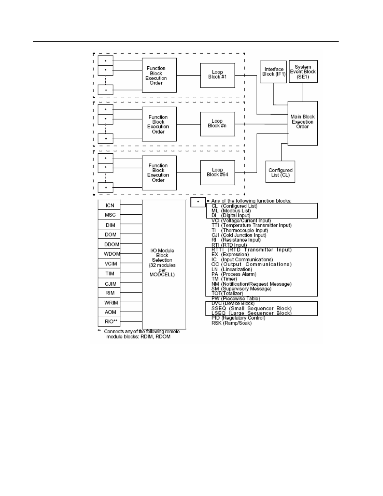
The MOD 30ML/Modcell database architecture is shown in the next figure:
1 - 3
Page 12
Command Series Migration to MOD 30ML
Function Codes – Introduction
Figure 1 .1.
Instrument
Database
Architecture
1 - 4
Page 13

Command Series Migration to MOD 30ML
I/O AND COMMUNICATION MODULE BLOCKS:
These blocks specify the physical I/O complement of the instrument. The following I/O
module blocks are available:
Type Function Availability
AIN Built-in universal analog input MOD 30ML
AOUT Built-in analog output MOD 30ML
VCIM Voltage or current input MOD 30ML and Modcell
TIM Thermocouple input MOD 30ML and Modcell
RIM 2 wire RTD / Resistance Input MOD 30ML and Modcell
WRIM 3 wire RTD / Resistance input MOD 30ML and Modcell
DIM Discrete input MOD 30ML and Modcell
Function Codes – Introduction
DOM Discrete output MOD 30ML and Modcell
DDOM Double Relay output MOD 30ML and Modcell
WDOM Form-C relay output MOD 30ML and Modcell
AOM Analog Output MOD 30ML and Modcell
ICN Instrument Communication Network (Peer-to-
MSC Modcell Serial Communication (RS232, Rs485
RIO Remote digital interface module MOD 30ML and Modcell
RDIM Remote digital input (extended digital inputs) MOD 30ML and Modcell
RDOM Remote digital output (extended digital outputs) MOD 30ML and Modcell
FUNCTION BLOCKS
There are three types of function blocks.
Process input function blocks configure input signal conditioning, engineering unit
conversion and linearization for inputs.
MOD 30ML and Modcell
peer)
MOD 30ML and Modcell
Modbus)
Algorithm function blocks define the user configured control functions on the
instrument.
Communication function blocks handle transfer of data between groups, as well as
transfer of data to the communication interfaces.
These are shown in the next table:
1 - 5
Page 14
Command Series Migration to MOD 30ML
Function Codes – Introduction
Type Description Availability
Input Function Blocks or signal conditioning blocks:
VCI Voltage or current MOD 30ML and Modcell
TI Thermocouple input MOD 30ML and Modcell
RTI RTD input MOD 30ML and Modcell
TTI Thermocouple transmitter input MOD 30ML and Modcell
RTTI RTD Transmitter input MOD 30ML and Modcell
RI Resistance input MOD 30ML and Modcell
DI Digital input MOD 30ML and Modcell
Communication function blocks
ML Modbus List block MOD 30ML and Modcell
CL Configured list block (for both ICN and Modbus) MOD 30ML and Modcell
System function blocks:
TL Tuning List Only MOD 30ML
DISP Display block (one required for each display) Only MOD 30ML
LP Loop Block (one required for each loop
MOD 30ML and Modcell
compound)
Algorithm blocks
PID PID Control with Setpoint, A/M switching and
MOD 30ML and Modcell
tracking etc.
EX Expression block (multi-purpose configurable
MOD 30ML and Modcell
block for arithmetic, continuous and discrete
logic)
IC Input Communication (for incoming peer-to-peer
MOD 30ML and Modcell
communication)
OC Output Communication (for outgoing peer-to-
MOD 30ML and Modcell
peer communication)
1 - 6
LN Linearization MOD 30ML and Modcell
PW Piecewise and inverse piecewise table MOD 30ML and Modcell
PA Process Alarm MOD 30ML and Modcell
PAD Process Alarm Display Only MOD 30ML
Page 15

Command Series Migration to MOD 30ML
Function Codes – Introduction
NM Notification Message MOD 30ML and Modcell
SM Supervisory Message MOD 30ML and Modcell
RSK Ramp – Soak Profile block MOD 30ML and Modcell
TOT Totalizer MOD 30ML and Modcell
TM Timer block MOD 30ML and Modcell
SEQ Sequencer MOD 30ML and Modcell
1 - 7
Page 16
Command Series Migration to MOD 30ML
Function Codes – Introduction
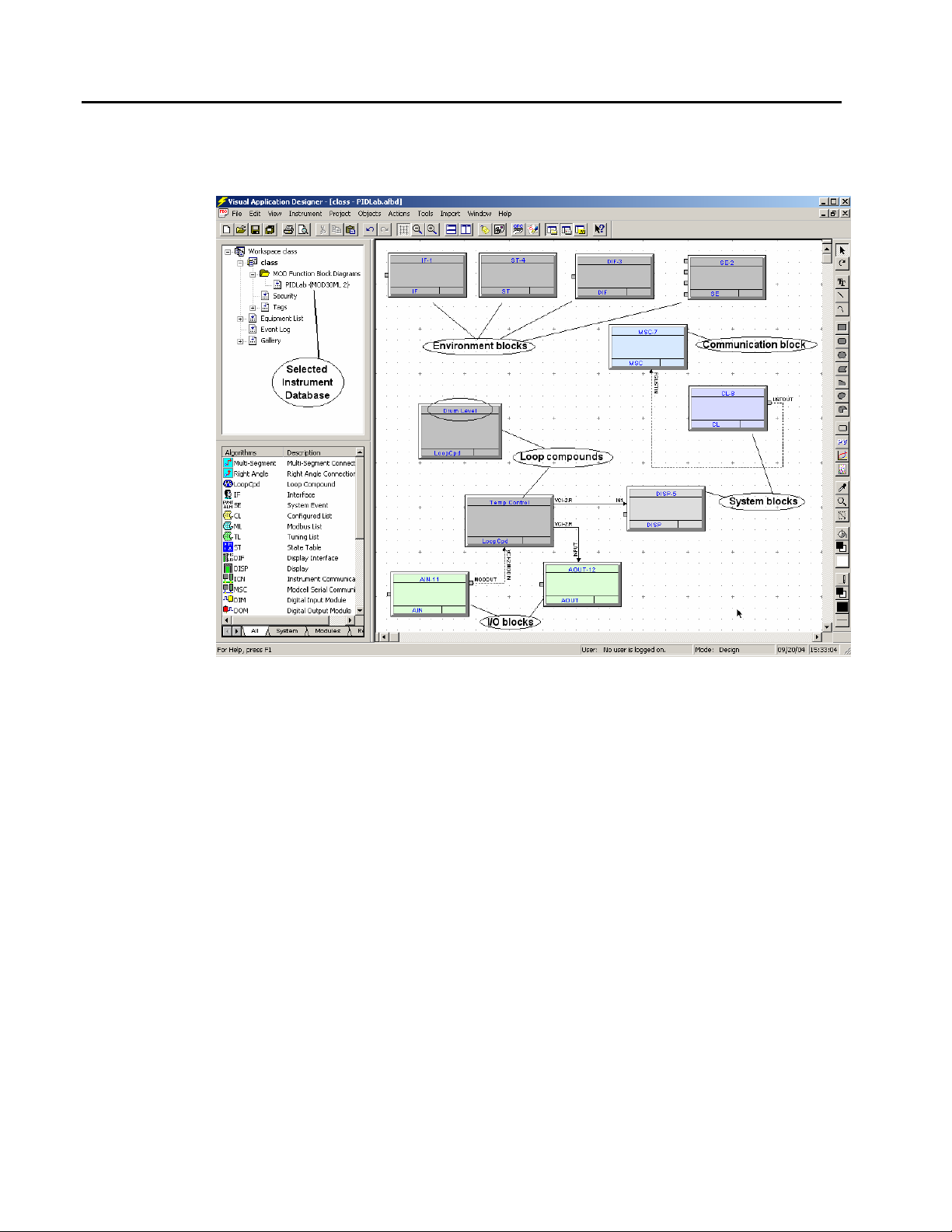
A typical instrument database as function block diagram configured in ViZapp is shown in
the next figure: A typical instrument database has the environment blocks, I/O blocks,
communication blocks, and loop compounds.
Figure 1 .2.
Instrument
database
Algorithm function blocks are configured inside a loop compound to implement control
strategies. Each loop compound has a loop block (LP) by default.
The next figure shows function blocks inside a loop compound:
1 - 8
Page 17
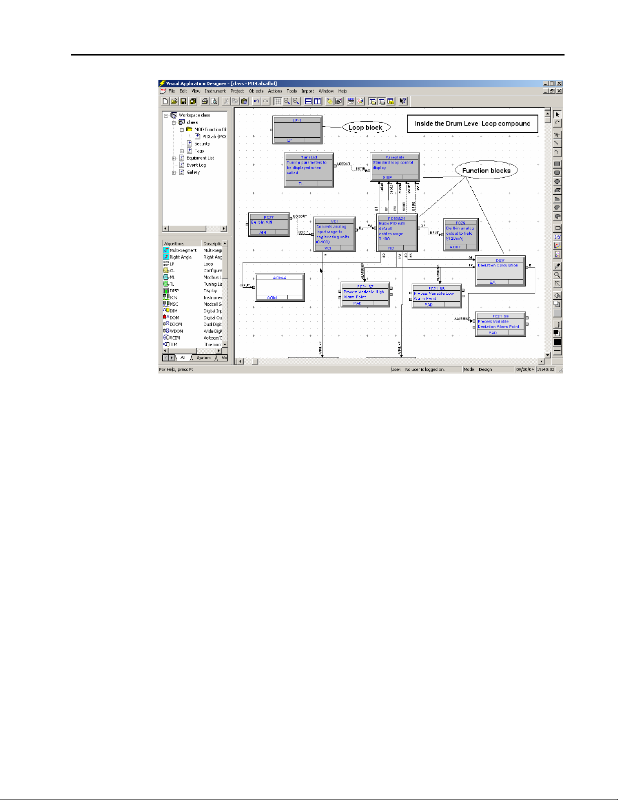
Figure 1 .3.
Function blocks
inside a loop
compound
Command Series Migration to MOD 30ML
Function Codes – Introduction
1 - 9
Page 18
Command Series Migration to MOD 30ML
Function Codes – Introduction
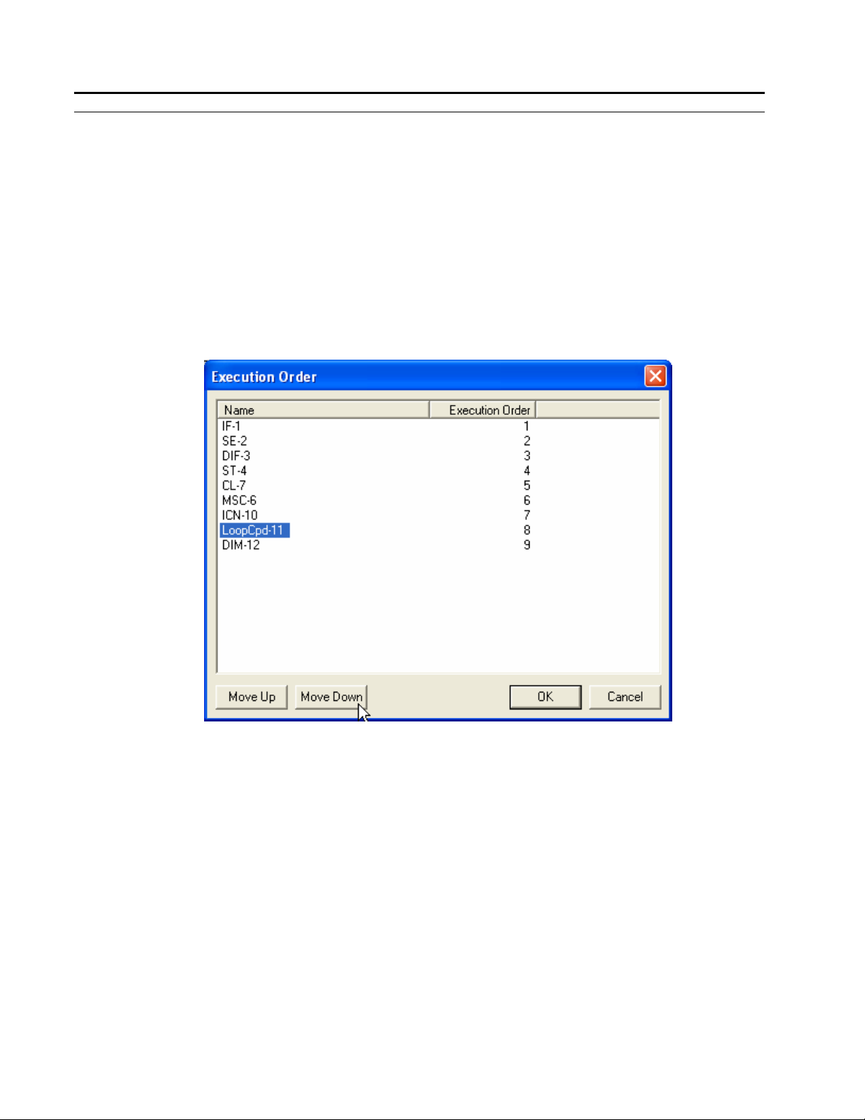
FUNCTION BLOCK EXECUTION ORDER:
The order in which the blocks in the database are executed is known as the Function Block
execution order. The execution order is set at the top level where the loop compounds are
added to the database. The default execution order for the loop compounds is the order in
which they are placed in the database. The default execution order for the blocks inside the
loop compound is the order in which they are placed inside the loop compound.
The execution order of the loop compounds and the function blocks can be changed by the
user during the configuration process.
To view and change the execution order of function blocks in a database, select Objects –
Set Execution Order – List Mode from the menu bar in ViZapp. See the following
figure:
Figure 1 .4.
Function blocks
Execution Order
1 - 10
Page 19
COMPOUNDS:
Function blocks in a database can be compounded (grouped) into a single group. This may
be done to functionally or visually organize the blocks in a database. Compounds can be
created at the top level or inside loop compounds. To compound a set of function blocks,
first select them and then select Objects – Compound from the ViZapp menu bar. When a
compound is made it creates a sub-level in the function block diagram and places the
blocks inside that level.
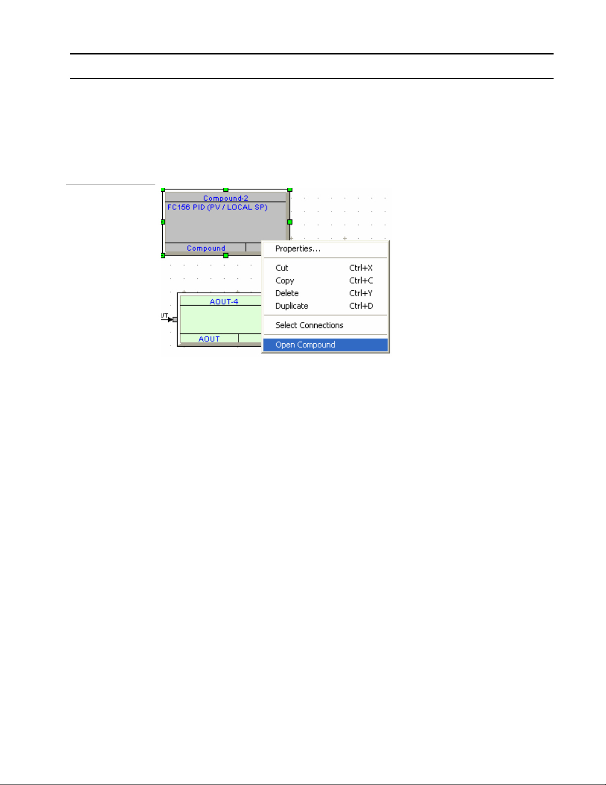
Figure 1 .5.
Open Compound
Command Series Migration to MOD 30ML
Function Codes – Introduction
The compound looks like a function block. See the above figure. To view the blocks,
select the compound and then right-click on the mouse to show a context sensitive menu
as shown in the above figure and then select Open – Compound.
If there were connections existing between the blocks that were compounded and other
blocks in the database, these connections are translated into jump objects inside the
compound.
1 - 11
Page 20
Command Series Migration to MOD 30ML
Function Codes – Introduction
Figure 1 .6.
Inside a Compound
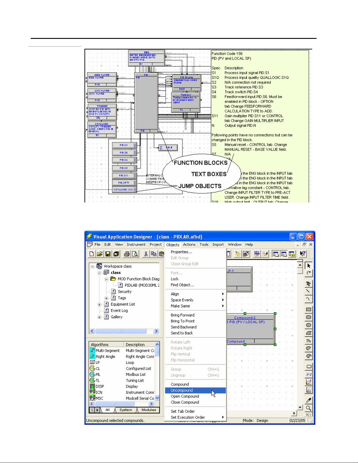
• You can ungroup a compound by un-compounding it. Select the compound by clicking on
Figure 1 .7.
Bailey FC Gallery
it and then select Objects from the menu bar and then select UnCompound from the
drop-down menu as shown in the next figure.
1 - 12
Page 21
Command Series Migration to MOD 30ML
Function Codes – Introduction
• This will un-group the function blocks and place them where the grouped compound was.
When you uncompound a compound, the function blocks come out selected. You can
move all of them to a desired location by dragging them with the left mouse button
pressed.
a The advantage of uncompounding is that you can place the function blocks at the same
level as other function blocks you might already have at that level thereby making the
connections easier.
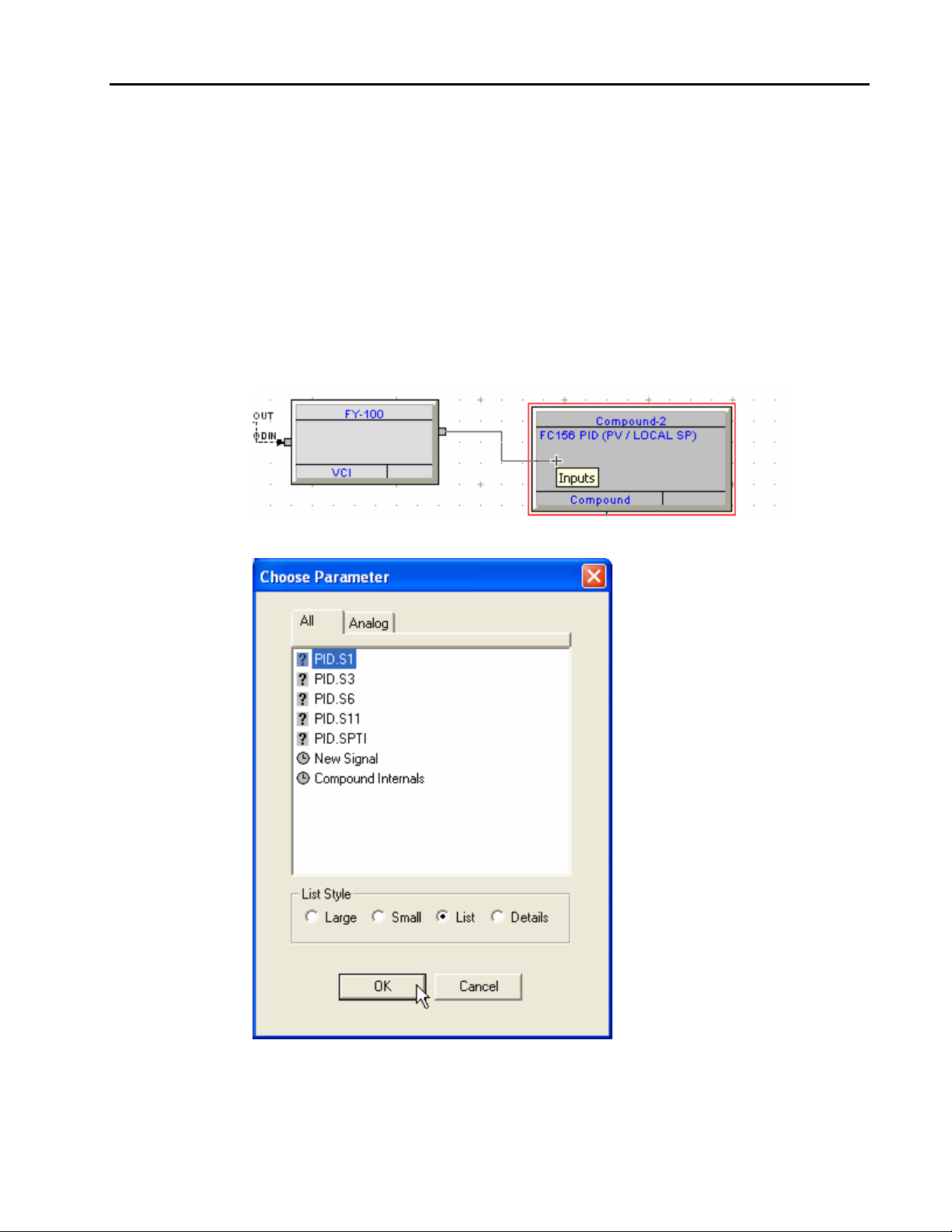
To connect to a compound from outside of it:
• Select the connector and select the attribute to connect from the desired block.
• Drag the line to the compound and click on it. See the figure below:
Figure 1 .8.
Right Angle
connection
• The Choose Parameter menu will be displayed as shown in the next figure:
Figure 1 .9.
Choose Parameter
• Select the desired jump object (if it was already present, for example PID.S1 in the above
figure) from the list and then click on OK.
1 - 13
Page 22
Command Series Migration to MOD 30ML
Function Codes – Introduction
• You can also double-click on the Compound Internals and then select from the displayed
list of function blocks inside and then select the block and then the attribute to connect to.
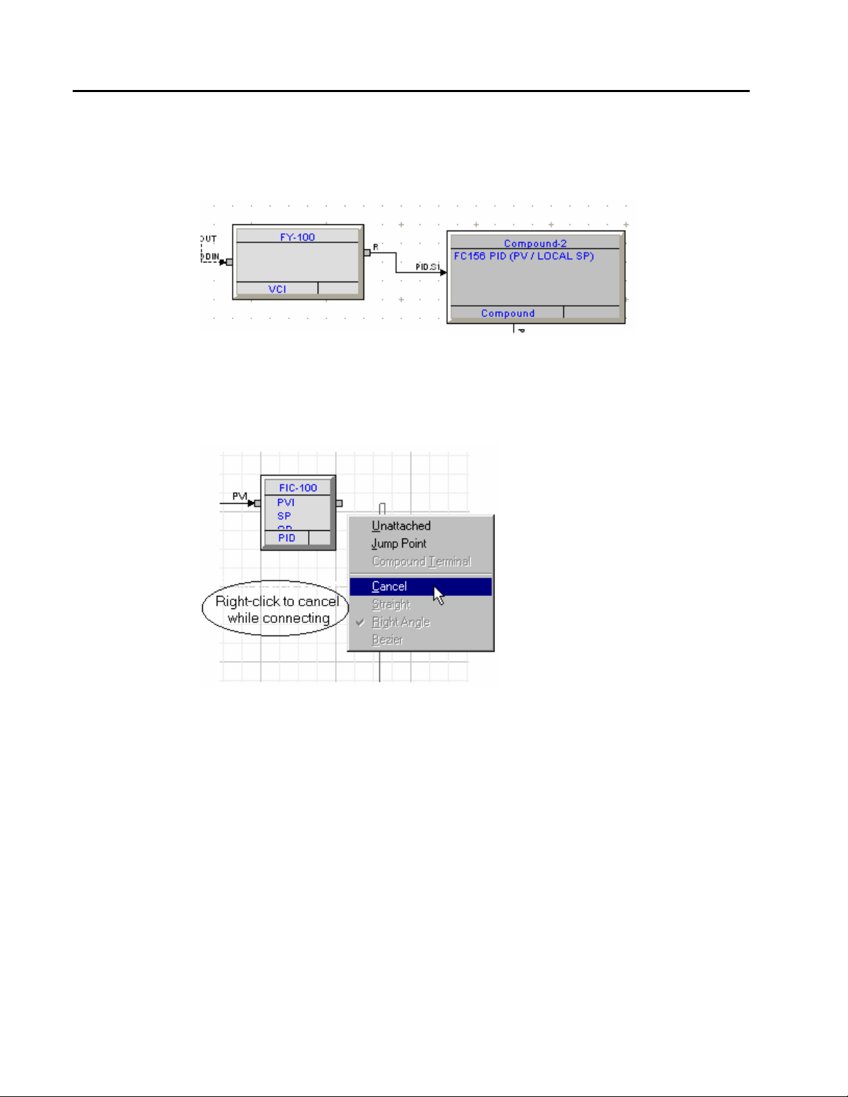
• This will complete the connection for the process variable input. The connection will look
like in the next figure:
Figure 1 .10.
If you made a mistake while connecting, or if you do not know where to connect, you can
always cancel it or get out of the connection mode by clicking on the right mouse button
to show a menu as shown below:
• Select Cancel from this menu to cancel the connection.
Figure 1 .11.
Cancel Connection
1 - 14
Page 23
LOOP COMPOUNDS
Loop compound is a special compound that contains a loop block. Loop compounds are
placed at the top level of a function block diagram (where the IF, DIF, SE and ST blocks
are located). All the function blocks other than Input, Output, Modules, Communication
and System blocks have to be configured inside a loop compound.
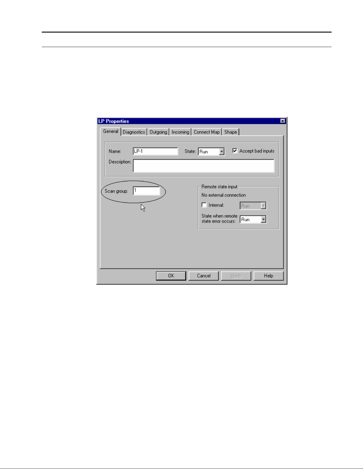
The loop block that is present inside the loop compound specifies the scan group at which
the blocks inside the loop compound get executed. See the next figure:
Figure 1 .12.
Cancel Connection
Command Series Migration to MOD 30ML
Function Codes – Introduction
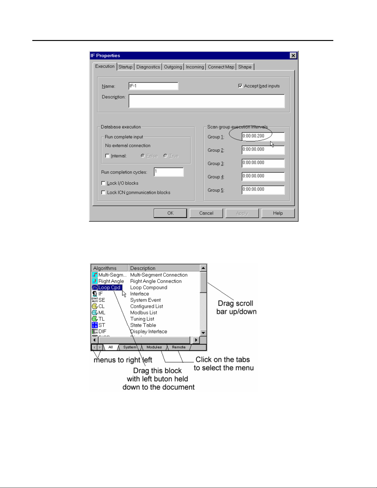
The scan groups are configured in the Interface Block at the top level. There could be as
many as 5 different scan groups. The scan time is in multiples of 50 ms and can be as low
as 50 ms.
The next figure shows the Interface (IF) block configuration:
1 - 15
Page 24
Command Series Migration to MOD 30ML
Function Codes – Introduction
Figure 1 .13.
Cancel Connection
Figure 1 .14.
Algorithms menu
To add a loop compound: Select the Loop Cpd (Loop compound) block from the
Algorithms window add it to the document. Do this by first locating the block in the menu
by selecting the All submenu at the bottom and then by dragging the scroll bar on the right
up/down. See the next figure:
1 - 16
• Drag the Loop Cpd block (Loop Compound) from the Algorithms menu on the left frame
to the right frame. Click on the Loop Cpd block with your left mouse button and then
drag it to the instrument document. Click on the mouse button to place the Loop
compound block with the other existing blocks (IF, SE, DIF and ST) on the right frame.
• Opening and closing of loop compound is exactly same as that of the compound explained
in the previous section.
Page 25

Command Series Migration to MOD 30ML
Function Codes – Introduction
• Loop compounds also have jump objects when connections are made from or to the
outside of the compound.
• Refer to the previous section (COMPOUNDS) for more information.
1 - 17
Page 26

Command Series Migration to MOD 30ML
Function Codes – Introduction
THE CONFIGURATION PROCESS
The steps involved configuring a MOD 30ML or Modcell controller are listed below:
1. Create a Workspace document in ViZapp
2. Create a Project document in ViZapp
3. Add a new instrument database for each controller to the project document.
4. Configure the instrument database in ViZapp.
5. Save and compile the instrument database
6. Configure the OPC Server (XModbus or ICN depending on which communication
protocol is used for connecting the controllers to the computer running ViZapp and
the OPC Server).
7. Add a device in the OPC Server for each controller that needs to be configured.
Communication settings for the device and the comm. Port should match that of the
instrument.
8. Download the compiled database from ViZapp using the OPC Server to the desired
instrument.
These steps are further explained in the next chapter and in the ViZapp training manual.
1 - 18
Page 27
Command Series Migration to MOD 30ML
Function Codes – Introduction
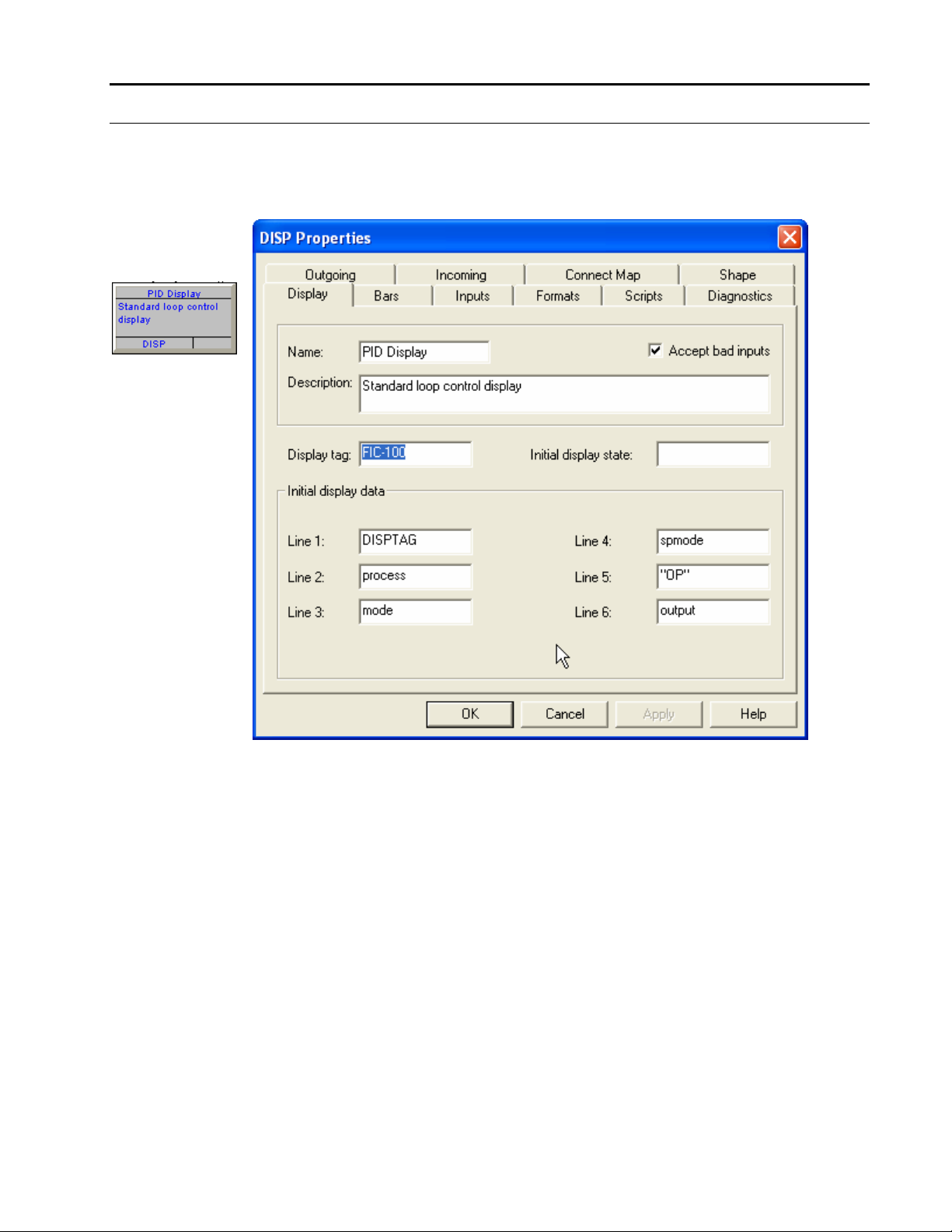
Procedure for adding the Display Tag to the Display Interface Block
Each display configured in the MOD 30ML has a unique display tag.
• Open the display block by double-clicking on it. See the next figure:
Figure 1 .15.
PID Display
• As an example, the default display tag name configured in this compound is FIC-100.
During runtime, you can scroll through the displays in this list by pressing the Tag button
on the instrument.
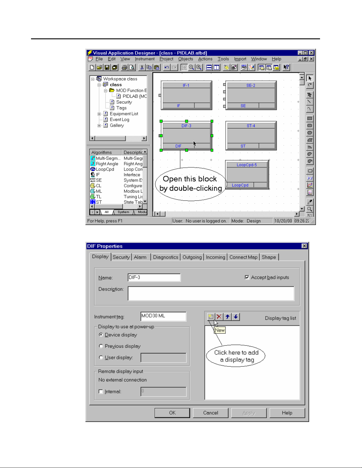
Close the compound and the loop compound and go to the top level of the function block
diagram where the IF, DIF, ST, SE blocks and the loop compounds are located. See figure
below.
Start by opening the DIF (Display Interface) block as shown in the figure below:
1 - 19
Page 28
Command Series Migration to MOD 30ML
Function Codes – Introduction
Figure 1 .16.
DIF block
Figure 1 .17.
DIF block
Click on the New button on this block as shown in figure below:
1 - 20
Page 29
Command Series Migration to MOD 30ML
Function Codes – Introduction
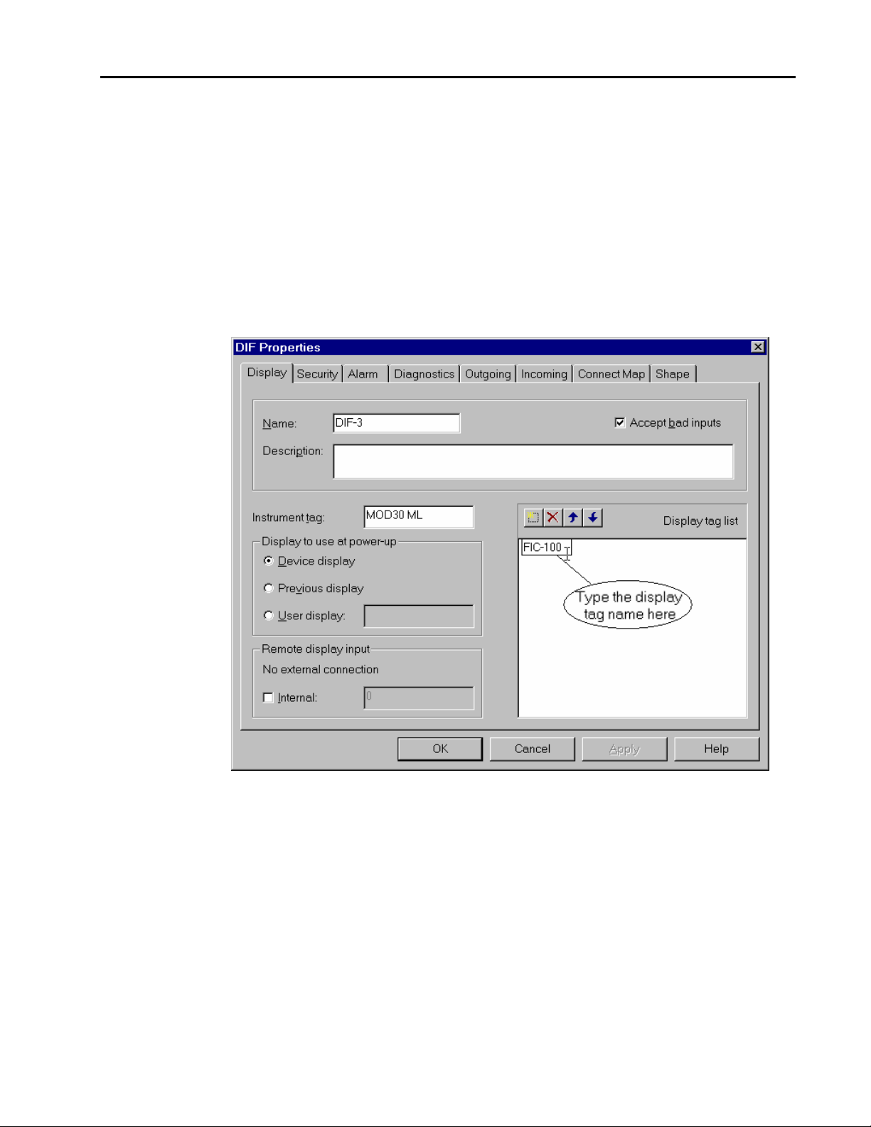
A text edit box will appear in the area below and you will see a text edit cursor blinking.
Type the name of your display tag (FIC-100 for example).
a If you had more than one display blocks in your configuration, you will need to add
their display tags in the DIF block as explained in the above step. The order in which
the display tags appear in this list is the order in which the displays will scroll when
you press the Tag button on the instrument. The display block gets executed by the
instrument when it is loaded on the face of the instrument. If you did not add the
display tag of a display block to this list, that display will not appear on the instrument
when you press the Tag button.
Figure 1 .18.
DIF block
The Instrument tag field displays a unique tag name for the instrument. An instrument can
have multiple displays each with its own tag name. The instrument tag is useful in
identifying the instrument.
• Click on the OK button when you are done.
1 - 21
Page 30
Command Series Migration to MOD 30ML
Function Codes – Introduction
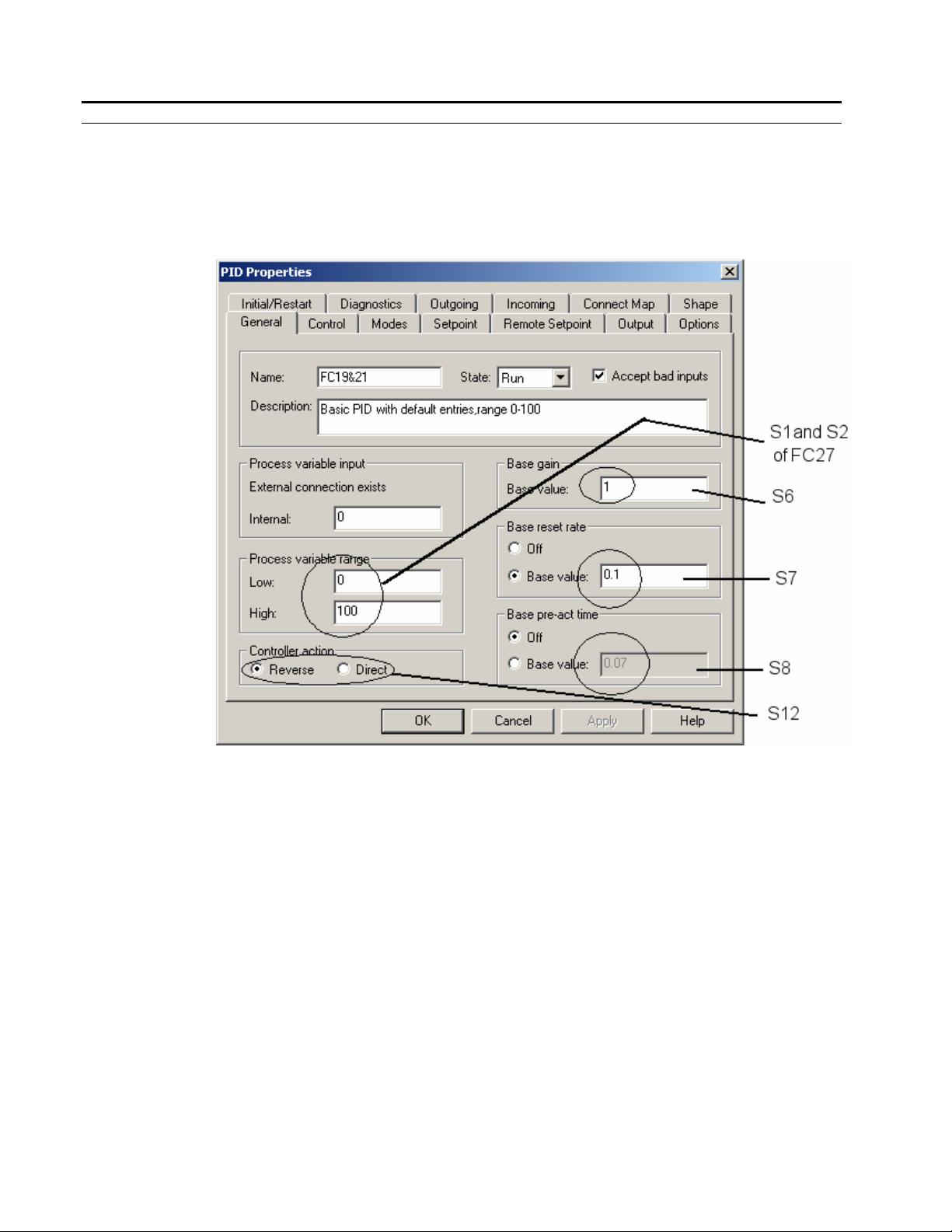
PID CONFIGURATION REFERENCE
The PID block in the MOD 30ML/Modcell is versatile and extremely powerful. We will
focus only on the parameters that we would typically use in a CLC or SLC controller.
• Open the PID block by double-clicking on it. The General tab will be displayed by
default as shown below:
Figure 1 .19.
Bailey FC Gallery
1 - 22
• Change the values as desired for the parameters as shown in the figure above.
• Click on the Control tab of the PID block. This tab contains configurable parameters that
are associated with the control algorithm used in the MOD 30ML/Modcell. See the
following figure:
Page 31

Figure 1 .20.
PID Control Tab
Command Series Migration to MOD 30ML
Function Codes – Introduction
• Select the Algorithm Type and change it to ESEO. This stands for a PID algorithm that
does the Proportional action on the Error, uses a Standard Integral action and Derivative
action on the Error and the Manual Reset is set to Off.
You can click on the Help button on the dialog box for context sensitive help and
explanation
Algorithm type (mnemonic - CATYPE) specifies the types of control actions for the
controller. The valid actions and their values are described below:
Gain (column 1):
O 0 Off. Gain response is turned off.
P 1 On Process. Gain response value is determined by process input signal.
E 2 On Error. Gain response value is determined by error signal.
Reset (column 2):
O 0 Off. Reset response is turned off.
S 4 Standard. Reset response is turned on and is operating with Standard Algorithm.
It can be used with externally generated adaptive gain or reset and/or external
feedback. Manual reset must be turned off.
1 - 23
Page 32

Command Series Migration to MOD 30ML
Function Codes – Introduction
M 8 MICRO-SCAN. Reset response is turned on and is operating with MICROSCAN algorithm. It can be used with either externally generated adaptive gain or
reset, but not with external feedback. Manual reset must be turned off.
The Standard Algorithm and Microscan Algorithm have different antireset windup
characteristics that affect how they approach limits. Otherwise, the two algorithms
integrate the same. Standard is necessary on applications requiring external feedback
and where better management of blips is required.
Microscan comes out of a limit one reset time constant ahead of the setpoint/process
crossover and is required on applications needing good startup characteristics without
overshooting and on applications with large setpoint changes which also require an
approach to the new setpoint without overshooting.
Pre-Act (column 3):
O 0 Off. Pre-Act response is turned off.
P 16 On Process. Pre-Act response value is determined by process signal.
E 32 On Error. Pre-Act response value is determined by error signal.
Manual Reset (column 4):
O 0 Off. Manual reset response is turned off.
E 64 Enabled. Manual reset response is turned on (only if reset response is turned
off).
1 - 24
Page 33

The valid actions for CATYPE are:
EOOO Gain on error, Reset off, Pre-Act off, manual reset off.
OSOO Gain off, standard Reset, Pre-Act off, manual reset off
PSOO Gain on process, standard Reset, Pre-Act off, manual reset off.
ESOO Gain on error, standard Reset, Pre-Act off, manual reset off.
OMOO Gain off, MICRO-SCAN Reset, Pre-Act off, manual reset off.
PMOO Gain on process, MICRO-SCAN Reset, Pre-Act off, manual reset off.
EMOO Gain on error, MICRO-SCAN Reset, Pre-Act off, manual reset off.
EOPO Gain on error, Reset off, Pre-Act on process, manual reset off
PSPO Gain on process, standard Reset, Pre-Act on process, manual reset off
Command Series Migration to MOD 30ML
Function Codes – Introduction
ESPO Gain on error, standard Reset, Pre-Act on process, manual reset off
PMPO Gain on process, MICRO-SCAN Reset, Pre-Act on process, manual reset off
EMPO Gain on error, MICRO-SCAN Reset, Pre-Act on process, manual reset off.
EOEO Gain on error, Reset off, Pre-Act on error, manual reset off
ESEO Gain on error, standard Reset, Pre-Act on error, manual reset off
EMEO Gain on error, MICRO-SCAN Reset, Pre-Act on error, manual reset off
EOOE Gain on error, Reset off, Pre-Act off, manual reset enabled
EOPE Gain on error, Reset off, Pre-Act on process, manual reset enabled
EOEE Gain on error, Reset off, Pre-Act on error, manual reset enabled.
1 - 25
Page 34

Command Series Migration to MOD 30ML
Function Codes – Introduction
• Click on the Setpoint tab to select the Setpoint configuration options. See the next figure:
• Change the Setpoint limits to desired values. Setpoint values to the PID algorithm are
limited to these numbers.
• Setpoint modes limited is used to apply limits to the setpoint when it is in a certain mode.
The limits can be applied to: None, Local, Remote, Track or their combinations. See the
next figure:
Figure 1 .21.
PID Setpoint Tab
1 - 26
Page 35

Figure 1 .22.
PID Setpoint Tab
Command Series Migration to MOD 30ML
Function Codes – Introduction
• Click on the Output tab to select the output configuration options. See the next figure:
• Change the output limits and range to desired values: Click on the Output tab of the PID
block. See the next figure:
• The output limits are applied to the active output when the proper output modes limited
condition is met. Output values from the PID algorithm are limited to these numbers.
• The output modes limited count value is used to limit the output modes to those selected.
The limits can be applied to: Auto, Manual&Auto, Auto&Track, Manual&Auto&Track.
• The output range high and low values represents the top and bottom of the output range.
The output range values are used to denormalize the output units.
Output Modes in MOD 30ML:
The PID output mode can be Manual or Auto or Track. When the output is in Manual
mode, the user can change the output from the faceplate. When the output is in Auto
mode, the PID block calculates the output.
When the output is in Track mode the output tracks the signal connected to the OPTI
(Output Track Input) attribute of the PID block. An external signal can be connected to the
OPTI attribute of the PID block or it can be an internal value in the PID block that can be
manually changed by the user from the faceplate. The output can be switched to Track
mode by the TCI (Track Command Input) attribute of the PID block. The data type of the
TCI is discrete and can be connected to switch the output mode to track (1 – track Enable,
0 – track Disable). An external signal can be connected to the TCI attribute of the PID
1 - 27
Page 36

Command Series Migration to MOD 30ML
Function Codes – Introduction
block or it can be an internal value in the PID block that can be manually changed by the
user from the faceplate.
This is in contrast to the SCL/CLC PID where the Track (S3 – Track Reference Signal) of
the PID block is enabled with the help of TS (S4 – track switch signal) for anti reset
windup during a Manual to Auto transfer. In the case of MOD 30ML/Modcell PID, this is
taken care automatically during the Manual/Auto transfer since the MOD 30ML/Modcell
PID block has the PID and M/A in one.
See the following figure where the Options tab of the PID block is shown:
Figure 1 .23.
PID Options Tab
1 - 28
• We have made some changes to the default configuration of the PID block. Click on OK
to accept the changes and close the PID block.
Page 37

BOOK 1
SECTION 2
GALLERY TUTORIAL
Page 38

Page 39

FOREWORD
OBJECTIVES
Function Codes – Gallery Tutorial
The ViZapp (Visual Application Designer) software has a library of function block
compounds that represent the function codes of the Bailey SLC Controller. These
compounds are created with the MOD 30ML/MODCELL function blocks. Each of the
compounds in the gallery is pre-configured to offer SLC functionality with in the MOD
30ML controller. This will make the migration from SLC to MOD 30ML, a much easier
process and reduce engineering time.
This tutorial will walk you through the configuration of MOD 30ML to perform SLC
functionality. We will use a pre-configured compound from ViZapp’s SLC Function code
gallery to configure the MOD 30ML.
After completing this lab you should know how to:
• Be familiar with the ViZapp Software
• Know how to create new workspace, project and instrument documents
• Know how to configure a MOD 30ML database using ViZapp Configurator for a simple
PID Control loop.
• Be able to setup communications for communicating to the MOD 30ML/MODCELL
instrument from the PC.
• Be able to build a PID loop faceplate display for displaying and changing process and
operator parameters.
• Know how to compile and download the database to the instrument
2- 1
Page 40

Command Series Migration to MOD 30ML
Function Codes – Gallery Tutorial
INSTRUCTIONS – CREATING A NEW WORKSPACE, PROJECT AND
DOCUMENT
1. Launch ViZapp: Select Programs from the Windows Start menu. Select ViZapp from the
menu. The ViZapp configurator will launch as shown in the next figure. As you will
notice, the configurator will be blank with no workspace loaded on the screen.
Figure 2 .1.
ViZapp
Configurator
Figure 2 .2.
File-New
Note that the configurator screen has two frames (left and right).
2. We will create a new Workspace and a new project in this step. Click on the File menu
on the menu bar at the top. Select New from the drop-down menu as shown in the next
figure:
• This will open the New dialog box as shown in the next figure. There are 2 tabs (sections)
in this dialog box and it displays the Project tab as default. Click on the Workspace tab.
2 - 2
Page 41

Figure 2 .3.
New Workspace
Command Series Migration to MOD 30ML
Function Codes – Gallery Tutorial
Figure 2 .4.
Browse
• By default, the workspace file is created in the Project folder that is located inside the
folder where the ViZapp software is installed. For example:
C:\Program Files\ViZApp\Project.
• We will change the location for the purpose of this lab. Click on the little button next to
the Location field. This will open the Browser for Folder dialog as shown in the next
figure:
• Select the desired drive (C or D or other) from this dialog by double-clicking on it. The
next figure shows the selection of the C drive for example. See next figure:
2 - 3
Page 42

Command Series Migration to MOD 30ML
Function Codes – Gallery Tutorial
• The New dialog box will redisplay
Figure 2 .5.
New Workspace
Figure 2 .6.
New Workspace
• Type a name for your workspace in the name field. For the purpose of this lab, we will
type CLASS as the name. See the next figure. Click on OK. The ViZapp Configurator
will redisplay with the workspace that is created as shown in the next figure:
2 - 4
Page 43

Figure 2 .7.
New Project
Command Series Migration to MOD 30ML
Function Codes – Gallery Tutorial
• Notice that the workspace Class is added to the project tree. We will create a new project
next. Click on the workspace name Class in the project tree to select it and then right-click
on it. A context menu will be displayed as shown in the next figure:
• Select New Project from this menu. The New dialog box will be redisplayed as shown in
the next figure:
• We will type the name Class for the project for the purpose of this lab. Notice that the
name of the location for this project changes to C:\Class. It creates a folder under the C:
drive (or any other drive you choose) automatically.
Figure 2 .8.
New Project
All project files and the instrument and display documents will be saved in this folder.
This makes project portability easier.
• The configurator will redisplay with a new workspace and a project as shown below:
2 - 5
Page 44

Command Series Migration to MOD 30ML
Function Codes – Gallery Tutorial
Figure 2 .9.
Class Workspace
• The left frame shows the project tree. The Workspace is at the root of this tree and
contains the Project, and other components such as Event Log and Components.
• The newly created workspace is given the same name as that of the project. The project
sub-tree or branch contains the components Security and Tags.
3. With what we have above, we have only created an environment to configure instrument
database and display files. Next we will create an instrument database. We will hereafter
call it the instrument document.
• Click on the New Document button on the tool bar or Select File-New form the menu bar
to display the New dialog box again as shown below:
2 - 6
Page 45

Figure 2 .10.
New Document
Command Series Migration to MOD 30ML
Function Codes – Gallery Tutorial
• The New dialog box shows the Document tab now. Select the type MOD Function Block
diagram by clicking on it and then type the name PIDLab for the document in the Name
field.
• This document will be created in the project folder \class automatically and will be added
to your Class project by default. See figure above.
4. When you create a new project, a file with the project name and file extension .APRJ will
be created. This file is called project file in the ViZapp installation directory.
The instrument document is basically the controller database or the configuration file. It is
also known as the MOD Function block diagram. This file has an extension .AFBD and is
saved in the project folder. The workspace we created is saved as a file with extension
.AWSP (Class.awsp) and a file with same name and .FEQP extension (Class.feqp) in the
root folder where the project folder is located.
IF you move your workspace and project to a different location/ drive, move the project
folder and the two files for the workspace (.AWSP and .FEQP), maintaining their relative
location.
• Click on OK. This will display the Choose Instrument Version dialog box as shown in
the next figure: This dialog box will display the different instrument ID module versions
(MODCELL and MOD 30ML).
2 - 7
Page 46

Command Series Migration to MOD 30ML
Function Codes – Gallery Tutorial
Figure 2 .11.
Choose
Instrument
Version
• Select MOD 30ML 2 from this list as our instrument version by clicking on it and then
click on the Close button.
• The Configurator will redisplay as shown below. The instrument database will be opened
Figure 2 .12.
Default Instrument
Database
on the right frame and the environment blocks (IF, SE, ST and DIF) for the MOD 30ML
database will be loaded.
Notice that the newly created document PIDLab is shown in the project tree attached to
the Project Class.
2 - 8
The algorithm blocks belonging to the instrument version selected will be shown as a
menu on the left frame.
Page 47

Command Series Migration to MOD 30ML
Function Codes – Gallery Tutorial
Each instrument will have its own database. The databases of the instruments will be
added to the corresponding project. This is done for convenience and the grouping is done
based on functionality or geography or logic.
For example, for a process area like a boiler house that has 2 boilers, there can be 2
projects called Boiler1 and Boiler2. Each project will have databases of the controllers that
control the boiler.
The following figure shows a workspace called Plant1 and 2 projects namely Boiler1 and
Boiler2.
Figure 2 .13.
Default Instrument
Database
2 - 9
Page 48

Command Series Migration to MOD 30ML
Function Codes – Gallery Tutorial
CONFIGURING SCAN GROUPS AND LOOP COMPOUNDS
5. Let us first configure a scan group:
There could be as many as five scan groups in an instrument database. The control loops
(database blocks connected together) are grouped into Loop Compounds. The Loop
Compounds can be assigned to any of these scan groups. All the blocks and compounds in
a particular scan group will be executed at the same scan rate configured for the group.
This way you can have many loops in the database and they can be executed at different
rates depending on their priority and speed of the process they are controlling.
• Notice that all the four blocks on the screen are selected. Reset the screen by deselecting
them by clicking on a blank space.
• Double-click on the IF (Interface) block. The Interface block will open as shown in the
next figure: The block is displayed in a visual notebook format, with tabbed “pages”
containing the parameters for configuration. The Execution tab (page) of this block will be
displayed by default.
Figure 2 .14.
Interface Block
6. We will now configure a typical PID control loop in this tutorial.
2 - 10
Application1: Typical PID control in the Loop Command Controller CLC03/04:
The following diagram shows a typical single loop control with local Setpoint and uses the
following function codes:
Analog Input AI – Function Code 27
PID control – Function Code 19
Page 49

Figure 2 .15.
Typical Loop
Configuration in
CLC 03/04
Command Series Migration to MOD 30ML
Function Codes – Gallery Tutorial
M/A Station – Function Code 21
Analog output AO – Function Code 29
In the case of SLC or CLC, the display faceplate operator interface functionality is
automatic and does not need any user configuration. The operator interface provides
display of the process variable, Setpoint, control output, control mode and tuning
parameters and access to change parameters such as Setpoint, control output, mode and
tuning parameters.
The MOD 30ML requires configuration for each function. There is a function block for
each function. You will need to add the required function blocks to the instrument
database. For example, if you need operator interface for the PID control you need to add
a DISP (display) block and for tuning you need to add the TL (tuning list) function block.
To perform a simple PID control loop that involves a 4-20 mA input, PID and a 4-20 mA
output in MOD 30ML, you need the following function blocks:
AIN (built-in analog input) block – There are 2 AIN blocks available. This block reads the
analog input and has some basic linearization capabilities.
VCI (Voltage or current input function) block – This block is capable of signal
conditioning, engineering unit range conversion and linearization.
PID block – This block generates the Setpoint, deviation, performs PID control and
Setpoint and output selection etc.
AOUT (built-in current output) block – There are 2 AOUT blocks available. This block is
capable of converting the PID output to 4-20 mA
DISP (display) block – This block provides the operator interface for the control
TL (tuning list) block – to configure the tuning parameters and provide operator interface
for them.
The PID block in the MOD 30ML combines PID control and M/A station. This is in
contrast to the SLC/CLC database where you would need both PID function code and an
M/A function code.
7. Add a loop compound. We will configure our control loop within this loop compound.
2 - 11
Page 50

Command Series Migration to MOD 30ML
Function Codes – Gallery Tutorial
• Select the Loop Cpd (Loop compound) block from the Algorithms window add it to the
document. Do this by first locating the block in the menu by selecting the All submenu at
the bottom and then by dragging the scroll bar on the right up/down. See the next figure:
Figure 2 .16.
Algorithms menu
Figure 2 .17.
Loop Compound
Properties
• Drag the Loop Cpd block (Loop Compound) from the Algorithms menu on the left frame
to the right frame. Click on the Loop Cpd block with your left mouse button and then
drag it to the instrument document. Click on the mouse button to place the Loop
compound block with the other existing blocks (IF, SE, DIF and ST) on the right frame.
8. Configure a name and description for the Loop Compound: Click once on this block with
your right mouse button. A menu as shown in the next figure will appear.
2 - 12
• Select Properties from the menu. The Algorithm Properties of the Loop Cpd block will be
displayed next as shown in the next figure.
• Type “Control” in the Name field.
Page 51

Figure 2 .18.
Loop Compound
Properties
Command Series Migration to MOD 30ML
Function Codes – Gallery Tutorial
• Type a description "This compound is for the Flow Control Loop"
• Click on OK to close the Properties.
9. Open the loop compound:
• Right-Click on the Control compound (Loop compound you just named) again and select
Open compound at the bottom of this menu.
2 - 13
Page 52

Command Series Migration to MOD 30ML
Function Codes – Gallery Tutorial
Figure 2 .19.
Open Compound
• The loop compound will open as shown below and will have a Loop block (LP) by
default.
2 - 14
Page 53

Figure 2 .20.
Inside the Loop
Compound
Command Series Migration to MOD 30ML
Function Codes – Gallery Tutorial
A loop compound is a compound or group that contains a loop block. You configure other
blocks and compounds inside the loop compound. The compound can be added to one of
the five scan groups defined in the Interface block. All the blocks inside the compound
will be executed at that scan rate.
10. Open the Loop block (LP-1) by double-clicking on it. The block will open as shown in the
next figure. We will not change anything in this block. Just notice that scan group this
compound belongs to defaults to Scan Group 1. (200 ms– refer to step 4 - Interface block).
2 - 15
Page 54

Command Series Migration to MOD 30ML
Function Codes – Gallery Tutorial
Figure 2 .21.
Loop Block
• Close the Loop block by clicking on the OK button.
2 - 16
Page 55

Command Series Migration to MOD 30ML
Function Codes – Gallery Tutorial
ADDING COMPOUND FROM THE GALLERY
11. We will now use a compound from the Bailey Function Code section of the gallery to
configure this control loop.
Compound Gallery: Pre-configured control loops and applications are stored in the
Gallery in the Vizapp Software. The gallery is basically a library of preconfigured
function blocks that are also connected for performing control and calculation tasks. The
software is shipped with a default gallery that includes most of the commonly used loops
and functions in the MOD 30ML. The user can also create configuration of frequently
used control applications and store them in this default gallery. The default gallery is
contained in the file Defaultgallery.fgal.
• To display the gallery, select Project from the menu bar again and then select Gallery-
Component Gallery from the drop-down menu as shown in the next figure:
Figure 2 .22.
Gallery Menu
• The gallery will be displayed as shown in the next figure:
2 - 17
Page 56

Command Series Migration to MOD 30ML
Function Codes – Gallery Tutorial
Figure 2 .23.
Bailey FC Gallery
• The compounds in this gallery have been given names. Some of the names FC# where # is
the Bailey function code number. There is a compound named FC156 PID (PV / LOCAL
SP) in the gallery. This compound can be used to configure the MOD 30ML for the CLC
Single loop control functionality. Select this compound from the list by clicking on it.
Verify the description of this compound in the description field at the bottom of the
Component Gallery dialog as shown in the above figure.
• Click on the Export button on the dialog.
2 - 18
Page 57

Figure 2 .24.
Bailey FC Gallery
Command Series Migration to MOD 30ML
Function Codes – Gallery Tutorial
• The exported compound will be placed inside the loop compound with in the instrument
document as shown in the figure above.
• The function blocks that make this compound are located inside this new compound. It is
basically a grouped set of function blocks.
• Click on an empty area of the database to unselect the compound.
For a detailed reference of this compound FC156 PID (PV / LOCAL SP), refer to the
chapter Function Code 156 PID with Local SP in the reference section of this manual.
2 - 19
Page 58

Command Series Migration to MOD 30ML
Function Codes – Gallery Tutorial
ADDING I/O
12. The loaded compound has all the function blocks for doing the PID control but does not
have inputs and outputs required for the PID. We will use the built-in analog input and
output of the MOD 30ML.
• The MOD 30ML has 2 built-in inputs and outputs and you can choose the first or second.
If you have already used up both the built-in inputs and outputs, you can add a module for
the additional input. The configuration will require one of the following blocks (VCIM,
TIM, RIM, WRIM) depending on the type of input.
• Add the following blocks to the database:
• AIN – Built-in Analog input
• VCI – Voltage or Current input function block
• AOUT – Built-in Current output block
You can either select the specific category at the bottom of the Algorithms menu first and
then the blocks or you can select the category All to pick any block.
Figure 2 .25.
Algorithm blocks in
the Loop
Compound
After you placed the above blocks in the database, the right frame on your configurator
screen should look something like the next figure.
2 - 20
13. Resize and move these blocks to fit them on the database workspace.
• Select a block by clicking on it. The selected block will have handles around it. See figure
below:
• Move the block with the left mouse button pressed on it and by moving the mouse.
Page 59

Figure 2 .26.
Move, Resize and
Configure
Figure 2 .27.
AIN Block
Command Series Migration to MOD 30ML
Function Codes – Gallery Tutorial
• Resize the block by dragging one of the handles (corner or side)
14. Configure these blocks:
• Configure the Analog Input block.
• Double-click on the AIN block to open its Properties menu as shown below:
• Type FT-100 as the name.
• Select Current as the Input type from the drop-down menu.
• Type the Input number as 2 and Description as shown in the above figure. This is the
built-in input 2 of the MOD 30ML. Note that changing the input type changes the Input
Low and High signal ranges automatically. This can also be manually changed.
• Click on OK when done.
2 - 21
Page 60

Command Series Migration to MOD 30ML
Function Codes – Gallery Tutorial
• The next function block VCI, is a signal conditioning block. This block is used for
converting the analog input range (voltage or current) to engineering units. The default
configuration of this block is as shown in the next figure:
Figure 2 .28.
VCI Properties
• Type the name and description for this block as shown above. Move the cursor to the
Linearization Type field and click on the down arrow. Select Modifies Square Root as the
type from the drop-down menu. This will compensate for errors at very low flow
measurements.
• Change the Range to 0 to 200 and Quality limits also to 0 to 200. The measured signal (4-
20mA or 1-5V) will be interpreted as 0 to 200 flow units.
• We will not change anything else in this menu. Click on the OK button to complete the
configuration of this block.
Configure the AOUT block: Open the built-in analog output (AOUT) block.
• Configure the built-in output number (1 or 2).
• Configure the Action for this output (direct or reverse). Direct action specifies 4-20 mA
output for 0 – 100% output range. Reverse action specifies 4-20 mA for 100 – 0% output
range.
• Refer to the next figure:
2 - 22
Page 61

Figure 2 .29.
PID Options Tab
Command Series Migration to MOD 30ML
Function Codes – Gallery Tutorial
• Click on OK to accept the changes and close the block.
2 - 23
Page 62

Command Series Migration to MOD 30ML
Function Codes – Gallery Tutorial
MAKING CONNECTIONS
15. The next step is to connect the blocks together.
• Click on the Multi-Segment connection item on the Algorithms menu to enable
connection mode. See figure below:
Figure 2 .30.
Algorithm Connection
• Move to the workspace on the right and click on the AIN block’s (FT-100 – source
Figure 2 .31.
Connecting blocks
• Move the cursor to the VCI block’s (destination block FY-100) input now. Moving the
Figure 2 .32.
Connecting blocks
block) output connection point as shown in the next figure. Notice that moving the cursor
over the output of a block, shows a fly-by box. This box shows the name of the output (for
example, in this case MODOUT).
cursor will draw a line.
2 - 24
• You will get a fly-by box that will say MODIN when you move over the input.
• Click on the input of the VCI block. See the figure above.
Page 63

Command Series Migration to MOD 30ML
Function Codes – Gallery Tutorial
Figure 2 .33.
Connecting blocks
• The connection will now be complete. The connection line will have the source name and
destination name displayed right on it as shown in the above figure.
The input connection points are on the left side of the blocks and the output connection
points are on the right hand side.
There might be more than one input or output for each block. All the inputs or outputs
need not be shown as connections attached to the block. To see all the inputs or outputs of
a block, you need to click right on the block in the connection mode.
As an example, the figure below shows the possible inputs of the PID block (destinations
for inputs into this block).
Figure 2 .34.
Choose parameter
for connecting
16. Connect the corrected flow as the process variable:
• Let us take Right angle connector this time. The right angle connector will connect the
blocks by horizontal and vertical lines instead of making a point to point straight
connection.
• Select the right angle connector from the Algorithms menu as shown below:
2 - 25
Page 64

Command Series Migration to MOD 30ML
Function Codes – Gallery Tutorial
Figure 2 .35.
Right Angle
connection
• Click on the output point of the FY-100 block. This point is the result of the FY-100 input
function block. The fly-by box will say R when you click on the output.
• Drag the line to the FC156 PID (PV/LOCAL SP) compound and click on it. See the
figure below:
Figure 2 .36.
Right Angle
connection
• The Choose Parameter menu will be displayed as shown in the next figure:
2 - 26
Page 65

Figure 2 .37.
Choose Parameter
Command Series Migration to MOD 30ML
Function Codes – Gallery Tutorial
• Select PID.S1 from the list and then click on OK. This will complete the connection for
the process variable input. The connection will look like in the next figure:
Figure 2 .38.
If you made a mistake while connecting, or if you do not know where to connect, you
can always cancel it or get out of the connection mode by clicking on the right mouse
button to show a menu as shown below:
• Select Cancel from this menu to cancel the connection.
2 - 27
Page 66

Command Series Migration to MOD 30ML
Function Codes – Gallery Tutorial
Figure 2 .39.
Cancel Connection
17. Connect the PID output from the compound to the analog output:
• Select the connector and then click on the FC156 PID (PV/LOCAL SP) compound and
click on it. The Choose Parameter menu will be displayed as shown below: Select PID.N
from the menu and click on OK.
Figure 2 .40.
Choose Parameter
2 - 28
• Drag the connection line to left of the AOUT block and connect to the Input point. The
connected blocks and the compound will look like in the next figure:
Page 67

Figure 2 .41.
Command Series Migration to MOD 30ML
Function Codes – Gallery Tutorial
2 - 29
Page 68

Command Series Migration to MOD 30ML
Function Codes – Gallery Tutorial
CHANGING ENGINEERING RANGES AND ALARM TRIP VALUES
18. The FC156 PID (PV/LOCAL SP) has default values for the process variable range (0
to100). We need to change this to 0 – 200 to match the input range defined in step 14.
• Open the compound by first selecting it and then by clicking on the right mouse button. A
context sensitive menu will appear as shown in the next figure:
Figure 2 .42.
Open Compound
Figure 2 .43.
Inside the FC 150
PID (PV/LOCAL
SP) Compound
• Click on the Open Compound item from this menu. This will open the compound and
display the function blocks inside. See the next figure:
2 - 30
• Select the function block ENG (Expression block). This function block is where you
would set the engineering ranges, alarm setpoints and initial PID settings. Double-click on
it to open it.
Page 69

Figure 2 .44.
ENG block
Command Series Migration to MOD 30ML
Function Codes – Gallery Tutorial
• Select the Inputs tab of this block. Double-click on the number for the input ENGHI
(Engineering High). See the above figure.
• Change the value of Internal data to 200. Click on OK.
• Double-click on the ALMHI input and change the High Alarm Trip-value to 175 as shown
I the next figure:
2 - 31
Page 70

Command Series Migration to MOD 30ML
Function Codes – Gallery Tutorial
Figure 2 .45.
ENG block
• Repeat the above process to configure the Low process alarm by changing the ALMLO
input of the ENG block.
• Click on OK and then OK on the ENG block configuration.
2 - 32
Page 71

Command Series Migration to MOD 30ML
Function Codes – Gallery Tutorial
If you press the ALARM key on the faceplate when the alarm is active, the instrument will
display the custom alarm display as shown in the next figure:
Figure 2 .46.
Faceplate
displaying a
process alarm
2 - 33
Page 72

Command Series Migration to MOD 30ML
Function Codes – Gallery Tutorial
CONFIGURING DISPLAY TAG FOR THE PID DISPLAY
19. Each display configured in the MOD 30ML has a unique display tag. The FC156 PID
(PV/LOCAL SP) has a pre-configured display.
• Open the display block PID Display by double-clicking on it. See the next figure:
Figure 2 .47.
PID Display
2 - 34
• The default display tag name configured in this compound is PID-101. Change it to FIC-
100. See the next figure:
Page 73

Figure 2 .48.
PID Display
Command Series Migration to MOD 30ML
Function Codes – Gallery Tutorial
• Click on OK to close the block.
2 - 35
Page 74

Command Series Migration to MOD 30ML
Function Codes – Gallery Tutorial
20. Close the compound:
• First click on a blank area of the function block diagram to de-select any block or
connection selected.
Figure 2 .49.
Close Compound
Figure 2 .50.
Close Compound
• Click on the right mouse button to show the context sensitive menu as shown in the figure
above.
• Select Close Compound from the menu.
• You should be back in the level where the loop compound, Loop blocks are located. See
the next figure:
2 - 36
Page 75

21. Add the Display Tag to the Display Interface Block: The next step is to add the display
• Start by opening the DIF (Display Interface) block as shown in the figure below:
Figure 2 .51.
Closing Compound
Command Series Migration to MOD 30ML
Function Codes – Gallery Tutorial
tag of the display block we configured in the previous steps to the display list in the
display interface block. During runtime, you can scroll through the displays in this list by
pressing the Tag button on the instrument.
• Click on the New button on this block as shown in figure below:
2 - 37
Page 76

Command Series Migration to MOD 30ML
Function Codes – Gallery Tutorial
Figure 2 .52.
Closing Compound
• A text edit box will appear in the area below and you will see a text edit cursor blinking.
• Type the name of your display tag (FIC-100). Refer to the next figure.
a If you had more than one display blocks in your configuration, you will need to add
their display tags in the DIF block as explained in the above step. The order in which
the display tags appear in this list is the order in which the displays will scroll when
you press the Tag button on the instrument. The display block gets executed by the
instrument when it is loaded on the face of the instrument. If you did not add the
display tag of a display block to this list, that display will not appear on the instrument
when you press the Tag button.
2 - 38
Page 77

Figure 2 .53.
Closing Compound
Command Series Migration to MOD 30ML
Function Codes – Gallery Tutorial
• Refer back to the figure 1-37 for the display block set up.
The Instrument tag field displays a unique tag name for the instrument. An instrument can
have multiple displays each with its own tag name. The instrument tag is useful in
identifying the instrument.
• Click on the OK button when you are done.
2 - 39
Page 78

Command Series Migration to MOD 30ML
Function Codes – Gallery Tutorial
SAVING DOCUMENTS
22. Save your Document.
Figure 2 .54.
File Menu
• It is essential to save your document at frequent intervals.
• Refer to the above figure. The highlighted item is the instrument document. Click on the
Save button on the toolbar at the top to save the document. You can also save a document
by selecting File-Save from the menu bar. This saves the instrument document.
• File – Save All on the menu bar will save the document, the project file and the workspace
file.
Note that Save only saves the currently opened document. If you made changes in other
documents and wish to save, you may select Save-All instead.
2 - 40
Page 79

Command Series Migration to MOD 30ML
Function Codes – Gallery Tutorial
SETTING UP COMMUNICATIONS WITH MODBUS
23. We need to setup communications for communicating with the MOD 30ML instrument so
that we can download the database to the instrument. We will use the built-in RS-232 port
of the instrument to download to the instrument via Modbus.
The instrument supports up to 2 communication ports. These ports can be used for
Modbus or ICN (Instrument Communication Network, a proprietary peer-to-peer
communication network). The built-in communication port can be used for either ICN or
Modbus.
The built-in communication port jumper is located on the main board of the instrument as
shown in the next figure. The possible positions are: RS232 (Modbus), RS 485 (Modbus)
and ICN.
Figure 2 .55.
Built-in
Communications
jumper
Figure 2 .56.
Jumper locations
for built-in comm.
port
Built-in Circuit Modular Circuit
RS-232 RS-485 ICN Jumper Removed
2 - 41
Page 80

Command Series Migration to MOD 30ML
Function Codes – Gallery Tutorial
The connections for the port are available in the terminals in the back. In the case of an
instrument that is not NEMA4, the RS 232 port is also available in the front at the bottom
of the faceplate.
• Add a MSC block (Modcell serial communications) to the workspace by dragging it from
Algorithms menu. Double-click on it to configure. The properties menu of the MSC block
will display as shown below:
Figure 2 .57.
MSC
Communication
block
• Type a name and description for this block.
• Select RS-232 (built-in) from the drop-down menu in the Type field.
• Leave all other entries in their default values and click on OK to save the configuration of
this block.
2 - 42
Page 81

Command Series Migration to MOD 30ML
COMPILING THE DATABASE
It is necessary to compile the database without errors before downloading to the
instrument.
Only compiled databases can be downloaded to the instrument.
24. Select Instrument-Compile from the menu bar.
Figure 2 .58.
Instrument Compile
Function Codes – Gallery Tutorial
Figure 2 .59.
Compile Setup
• The Compile Setup dialog box as shown below will appear. Click on OK (Do not reassign
block occurrence numbers).
• The Interface File Options dialog box will be displayed as shown next. The interface files
are needed for integrating an HMI system with the controller and requires configuration of
a CL (Configured List) block in this database. It is beyond the scope of this lab and we do
not need to create an interface file.
• Click on the Cancel button on this dialog box.
2 - 43
Page 82

Command Series Migration to MOD 30ML
Function Codes – Gallery Tutorial
Figure 2 .60.
Interface File
Options for Modbus
• If the database has errors, it will not be compiled successfully. A list of errors will be
displayed on the screen in a sub-window along with other information such as the number
of errors, warnings and info messages as shown below:
2 - 44
Page 83

Figure 2 .61.
Information Window
Command Series Migration to MOD 30ML
Function Codes – Gallery Tutorial
• You can double-click on an error to open the block that has a configuration problem. If the
database has no errors, there is a message saying that the Compile was completed without
error.
• Also look for messages on database size and current consumption of the instrument.
• You can close this info sub-window by right-clicking on the window and then clicking on
the resulting Hide Window button or by selecting View-Information from the menu bar
at the top.
Refer to chapter 4 in the ViZapp Training manual (IB-VIZAPP-TUT) after
completing the tutorial for setting up the OPC Server and downloading the
database to the MOD 30ML Controller.
2 - 45
Page 84

Command Series Migration to MOD 30ML
Function Codes – Gallery Tutorial
2 - 46
Page 85

BOOK 2
REFERENCE
SECTION 1
PRE-CONFIGURED CONTROL
STRATEGIES
Page 86

Page 87

Pre-configured Single Loop PID Control
GENERAL DESCRIPTION
UTILIZATION
The advanced PID controller function code implements a proportional integral derivative
controller.
This control strategy has a loop compounds (SINGLE LOOP CONTROL) with PID
loops with local setpoint, I/O and other function blocks.
The loop compound has the function code compound FC156 – PID internally. This is
PID with Local SP and uses a PID block, PAD (Process Alarm Display) blocks and a
variety of other blocks to perform a full-pledged PID with PV and Local Setpoint. The
PID is advanced with feed-forward control, bump-less transfers and other features.
Load the loop compound at the top level (where the IF, DIF, SE and ST blocks are
located) of the function block diagram.
Figure P1.1.
PID with Local SP
The built-in input 1 (AIN1) and built-in output 1 (AOUT1) are used in the loop.
P1- 1
Page 88

Command Series Migration to MOD 30ML
Pre-configured Single Loop PID Control
EXPLANATION
Configuration with this compound requires understanding of the compound and how the
PID block is configured in the MOD 30ML/Modcell controllers. Following is the
reference that includes listing of most commonly used / changed attribute and inputs and
outputs. Necessary block configuration tabs are also explained to make it easier.
INPUTS – OUTPUTS
The I/O table is identical to both the loop compounds.
Signal Block Type Description
S1 PID Input – S1
Floating Point
S1Q QUALLOGIC Output – S1Q
Boolean (Discrete)
S2 N/A N/A N/A
S3 PID Input – S3
Floating Point
S4 PID Input – S4
Boolean
S5 PID Input – Floating
Point
S6 PID Input – S6
Floating Point
Result (R) of the VCI block VCI1 is
already connected to PID.S1 signal of
the compound for the first loop.
Process Input signal.
Connect to the QUALLOGIC.S1Q
signal of the compound. Process Input
Quality
Connect to the PID.S3 signal of the
compound. Track Reference.
Connect to the PID.S4 signal of the
compound. Track Switch.
Change in the Control tab of the
corresponding PID block. Change the
value for MANUAL RESET – BASE
VALUE.
Feed-forward input for the PID. Enable
in the Options tab of the PID block.
Change the calculation type to Add.
Connect the feed forward input to the
PID.S6 signal of the compound.
P1- 2
S7 N/A N/A N/A
S8 N/A N/A N/A
S9 N/A N/A N/A
S10 N/A N/A N/A
S11 PID Input – S11
Floating Point
Gain Multiplier input for the PID.
Connect to the PID.S11 signal of the
compound or change in the Control tab
Page 89

Command Series Migration to MOD 30ML
Pre-configured Single Loop PID Control
of the PID block. Change the value for
GAIN MULTIPLIER INPUT.
S12 ENG Input – GAIN
Floating Point
S13 ENG Input – RESET
Floating Point
S14 ENG Input – PREACT
Floating Point
S15 PID Input – Floating
Point
S16 PID Input – Floating
Point
Proportional Gain Kp. Enter in the ENG
block. Open the Inputs tab and select
GAIN to change the value.
Integral Reset in resets/min (RPM) Ki.
Enter in the ENG block. Open the
Inputs tab and select the input RESET
to change the value.
Derivative rate in minutes Kd. Enter in
the ENG block. Open the Inputs tab and
select the input PREACT to change the
value.
Derivative Lag constant Ka. Enter the
value in the PID block. Open the
Control tab and change the INPUT
FILTER TPE to PRE-ACT USER and
type the value in the INPUT FILTER
TIME field.
High Output Limit. Enter the value in
the PID block. Open the Output tab and
change the OUTPUT LIMITS HIGH
field and OUTPUT RANGE HIGH
field.
S17 PID Input – Floating
Point
Low Output Limit. Enter the value in
the PID block. Open the Output tab and
change the OUTPUT LIMITS LOW
field and OUTPUT RANGE LOW
field.
S18 PID Input – Count Algorithm Type. Choose the type in the
PID block. Open the Control tab and
select the value using the
ALGORITHM TYPE drop-down
menu.
S19 N/A N/A N/A
S21 PID Input – Discreet Controller Action. Choose the action in
the PID block. Open the General tab
and select the desired CONTROLLER
ACTION.
N PID Output – N
Floating Point
Output of the compound. PID.N is
already Connected to the Input attribute
of the built-in output block AOUT1 for
P1- 3
Page 90

Command Series Migration to MOD 30ML
Pre-configured Single Loop PID Control
S22 N/A N/A N/A
S23 N/A N/A N/A
the first loop.
SPTI PID Input – Floating
Point
Setpoint track input. Connect to the
PID.SPTI signal of the compound.
P1- 4
Page 91

Figure P1.2.
PID with Local SP
Command Series Migration to MOD 30ML
Pre-configured Single Loop PID Control
To configure the inputs:
Open the AIN block AIN1 for input 1. See figure below:
You can change the Input Type and Linearization Type for the built-in input 1 here.
Specify the Input Signal Range also.
The VCI block ENG UNITS 1 in the loop compound is used for converting the voltage,
millivolts or current input signal to engineering units. See figure below:
Change the Linearization type (Linear, Square, Square root, Modified Square, Modified
Square root) as required for the input signal and specify the Engineering Range and
Quality Limits.
P1- 5
Page 92

Command Series Migration to MOD 30ML
Pre-configured Single Loop PID Control
Figure P1.3.
PID with Local SP
You will need to use a different input function block if the input selected in the AIN block
is other than voltage / current. Use the following rule:
Input Type Input Function block Type
Current, Voltage, Milli voltage VCI (voltage or current input)
TTI (thermocouple transmitter input)
RTTI (RTD transmitter input)
Thermocouple TI (thermocouple input)
RTD RTI (RTD Input)
Resistance RI (resistance Input)
P1- 6
Page 93

Figure P1.4.
PID with Local SP
Display Block
Command Series Migration to MOD 30ML
Pre-configured Single Loop PID Control
To change the display tag name for the PID:
Open the display block PID Display inside the compound FC156 PID (PV / LOCAL SP)
and change the Display Tag under the Display tab. See figure below:
The display tag name also needs to be entered into the DIF (Display Interface Block) at
the top level of the database. See the section: Procedure for adding the Display Tag to
the Display Interface Block in the chapter Introduction for more information.
P1- 7
Page 94

Command Series Migration to MOD 30ML
Pre-configured Single Loop PID Control
To enable feedforward control and change the feedforward type (S6):
Open the PID block and select the Options tab. See figure below:
Figure P1.5.
PID with Local SP
Connect the desired signal to the feedforward input (PID.S6) of the compound.
P1- 8
Page 95

Figure P1.6.
PID with Local SP
Command Series Migration to MOD 30ML
Pre-configured Single Loop PID Control
To connect / change the value of the Gain Multiplier input (S11):
Make a connection into the PID.S11 signal of the compound.
To enter a local value, open the respective PID block and select the Control tab. Check
the Internal checkbox in the Gain Multiplier Input field and enter a value in the value in
the text field. See the next figure:
P1- 9
Page 96

Command Series Migration to MOD 30ML
Pre-configured Single Loop PID Control
To change the value of the Manual Reset input (S5):
To enter a local value, open the PID block and select the Control tab. Enter a value in the
Manual Reset – Base Value field.
See figure below:
Figure P1.7.
PID with Local SP
P1- 10
Page 97

Figure P1.8.
PID with Local SP
Command Series Migration to MOD 30ML
Pre-configured Single Loop PID Control
To change the values of the following:
Proportional Gain - S12
Integral Reset – S13
Derivative Rate – S14
To enter a local value, open the ENG function block (Expression block) and select the
Inputs tab. Double click on the number next to the desired input GAIN, RESET,
PREACT) and change the value.
See figure below:
P1- 11
Page 98

Command Series Migration to MOD 30ML
Pre-configured Single Loop PID Control
To change the value of the Derivative Lag Constant (S15):
Open the PID block and open the Control tab. Change the Input Filter Type to Pre-act,
User. Type a value in floating point units in the Input Filter Time field.
See figure below:
Figure P1.9.
PID with Local SP
P1- 12
The filter time in minutes (floating point value) when USER is specified as the filter type.
Otherwise, it is 0.0.
0.0 = no filtering (last sampled value is the input value)
1.0 = 1 minute
1000.0 = 1000 minutes (maximum value)
Note that exceptionally large values tend to maintain the previous value whereas very
small values tend to maintain the most recent sampled value.
Page 99

Figure P1.10.
PID with Local SP
Command Series Migration to MOD 30ML
Pre-configured Single Loop PID Control
To change the value of the Output Limits (S16, S17):
Open the PID block and open the Output tab. Change the values for the Output Limits –
Low and High and Output range – Low and High.
See figure below:
P1- 13
Page 100

Command Series Migration to MOD 30ML
Pre-configured Single Loop PID Control
To change the Algorithm Type (S18):
Open the PID block and open the Control tab. Change the type for the control algorithm
by selecting the desired option from the Algorithm Type drop-down menu.
See figure below:
Figure P1.11.
PID with Local SP
P1- 14
For more information about the Algorithm Type, click on the Help button or refer to the
Tutorial in this book.
 Loading...