


53MC5000
Table of contents
 Loading...
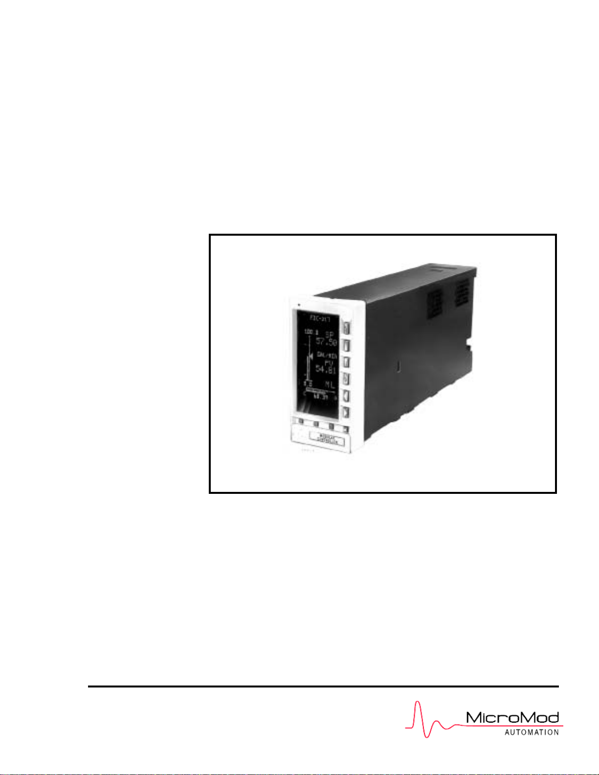
INSTALLATION GUIDE
Multi-Loop Process Controller
53MC5000
MICRO-DCI
.
MODULAR CONTR OLLER
PN24976
Rev1
MicroMod Automation, Inc.
The Company
MicroMod Automation is dedicated to improving customer efficiency by providing the most ost-effective, application-specific process solutions
available. We are a highly responsive, application-focused company with years of expertise in control systems design and implementation.
We are committed to teamwork, high quality manufacturing, advanced technology and unrivaled service and support.
The quality, accuracy and performance of the Company's products result from over 100 years experience, combined with a continuous
program of innovative design and development to incorporate the latest technology.
Use of Instructions
Although Warning hazards are related to personal injury, and Caution hazards are associated with equipment or property damage, it
must be understood that operation of damaged equipment could, under certain operational conditions, result in degraded process
system performance leading to personal injury or death. Therefore, comply fully with all Warning and Caution notices.
Information in this manual is intended only to assist our customers in the efficient operation of our equipment. Use of this manual for
any other purpose is specifically prohibited and its contents are not to be reproduced in full or part without prior approval of MicroMod
Automation, Inc.
Licensing, Trademarks and Copyrights
MOD 30 and MOD 30ML are trademarks of MicroMod Automation, Inc.
MODBUS is a trademark of Modicon Inc. Copyright 2005, MicroMod Automation Inc. (September 2005)
Health and Safety
To ensure that our products are safe and without risk to health, the following points must be noted:
The relevant sections of these instructions must be read carefully before proceeding.
1. Warning Labels on containers and packages must be observed.
2. Installation, operation, maintenance and servicing must only be carried out by suitably trained personnel and in accordance with the
information given or injury or death could result.
3. Normal safety procedures must be taken to avoid the possibility of an accident occurring when operating in conditions of high
4. pressure and/or temperature.
5. Chemicals must be stored away from heat, protected from temperature extremes and powders kept dry. Normal safe handling
procedures must be used.
6. When disposing of chemicals, ensure that no two chemicals are mixed.
Safety advice concerning the use of the equipment described in this manual may be obtained from the Company address on the back
cover, together with servicing and spares information.
Ì Warning. An instruction that draws attention to the risk of
injury or death.
. Note. Clarification of an instruction or additional
information.
. Caution. An instruction that draws attention to the risk of
the
p
roduct
,
p
rocess or surroundin
g
s.
i Information. Further reference for more detailed
information or technical details.
All software, including design, appearance, algorithms and source
codes, is copyrighted by MicroMod Automation, Inc. and is owned
by MicroMod Automation or its suppliers.

Table of Contents
1.0 INTRODUCTION . . . . . . . . . . . . . . . . . . . . . . . . . . . . . . . . . . . . . . . . . . . . . . . . . . 1-1
1.1 DESCRIPTION . . . . . . . . . . . . . . . . . . . . . . . . . . . . . . . . . . . . . . . . . . . . . . . . . . . . . . . . . . . . . . . . . 1-1
1.2 USING THIS MANUAL . . . . . . . . . . . . . . . . . . . . . . . . . . . . . . . . . . . . . . . . . . . . . . . . . . . . . . . . . . . . 1.1
1.3 MODEL NUMBER BREAKDOWN. . . . . . . . . . . . . . . . . . . . . . . . . . . . . . . . . . . . . . . . . . . . . . . . . . . 1-2
2.0 INSTALLATION . . . . . . . . . . . . . . . . . . . . . . . . . . . . . . . . . . . . . . . . . . . . . . . . . . . 2-1
2.1 INSPECTION. . . . . . . . . . . . . . . . . . . . . . . . . . . . . . . . . . . . . . . . . . . . . . . . . . . . . . . . . . . . . . . . . . . 2-1
2.2 LOCATION. . . . . . . . . . . . . . . . . . . . . . . . . . . . . . . . . . . . . . . . . . . . . . . . . . . . . . . . . . . . . . . . . . . . . 2-1
2.3 MOUNTING . . . . . . . . . . . . . . . . . . . . . . . . . . . . . . . . . . . . . . . . . . . . . . . . . . . . . . . . . . . . . . . . . . . . 2-1
2.3.1 GENERAL . . . . . . . . . . . . . . . . . . . . . . . . . . . . . . . . . . . . . . . . . . . . . . . . . . . . . . . . . . . . . . . 2-1
2.3.2 MOUNTING PROCEDURE . . . . . . . . . . . . . . . . . . . . . . . . . . . . . . . . . . . . . . . . . . . . . . . . . . 2-2
2.4 INTERCONNECTIONS . . . . . . . . . . . . . . . . . . . . . . . . . . . . . . . . . . . . . . . . . . . . . . . . . . . . . . . . . . . 2-6
2.4.1 PREPARATORY . . . . . . . . . . . . . . . . . . . . . . . . . . . . . . . . . . . . . . . . . . . . . . . . . . . . . . . . . . 2-6
2.4.2 WIRING PROCEDURE . . . . . . . . . . . . . . . . . . . . . . . . . . . . . . . . . . . . . . . . . . . . . . . . . . . . . 2-6
2.4.2.1 POWER INPUT . . . . . . . . . . . . . . . . . . . . . . . . . . . . . . . . . . . . . . . . . . . . . . . . . . . . 2-6
2.4.2.1.1 DC Power: . . . . . . . . . . . . . . . . . . . . . . . . . . . . . . . . . . . . . . . . . . . . . . . . . 2-6
2.4.2.1.2 AC Power: . . . . . . . . . . . . . . . . . . . . . . . . . . . . . . . . . . . . . . . . . . . . . . . . . 2-7
2.4.2.2 VOLTAGE INPUT . . . . . . . . . . . . . . . . . . . . . . . . . . . . . . . . . . . . . . . . . . . . . . . . . . . 2-7
2.4.2.3 CONTACT INPUTS . . . . . . . . . . . . . . . . . . . . . . . . . . . . . . . . . . . . . . . . . . . . . . . . . . 2-7
2.4.2.4 CURRENT OUTPUT . . . . . . . . . . . . . . . . . . . . . . . . . . . . . . . . . . . . . . . . . . . . . . . . . 2-7
2.4.2.5 CONTACT OUTPUTS . . . . . . . . . . . . . . . . . . . . . . . . . . . . . . . . . . . . . . . . . . . . . . . . 2-7
2.4.3 FACTORY SET CALIBRATION . . . . . . . . . . . . . . . . . . . . . . . . . . . . . . . . . . . . . . . . . . . . . . . 2-8
2.5 CORD SETS . . . . . . . . . . . . . . . . . . . . . . . . . . . . . . . . . . . . . . . . . . . . . . . . . . . . . . . . . . . . . . . . . . . 2-11
2.5.1 GENERAL . . . . . . . . . . . . . . . . . . . . . . . . . . . . . . . . . . . . . . . . . . . . . . . . . . . . . . . . . . . . . . . 2-11
2.5.2 INSTALLATION . . . . . . . . . . . . . . . . . . . . . . . . . . . . . . . . . . . . . . . . . . . . . . . . . . . . . . . . . . . 2-11
2.5.3 INTERCONNECTIONS . . . . . . . . . . . . . . . . . . . . . . . . . . . . . . . . . . . . . . . . . . . . . . . . . . . . . 2-11
2.6 GROUNDING . . . . . . . . . . . . . . . . . . . . . . . . . . . . . . . . . . . . . . . . . . . . . . . . . . . . . . . . . . . . . . . . . 2-15
3.0 FUNCTIONALITY. . . . . . . . . . . . . . . . . . . . . . . . . . . . . . . . . . . . . . . . . . . . . . . . . . 3-1
3.1 CONTROLLER FRONT PANEL . . . . . . . . . . . . . . . . . . . . . . . . . . . . . . . . . . . . . . . . . . . . . . . . . . . . 3-3
3.1.1 DISPLAY . . . . . . . . . . . . . . . . . . . . . . . . . . . . . . . . . . . . . . . . . . . . . . . . . . . . . . . . . . . . . . . . 3-3
3.1.1.1 ALARM ANNUNCIATION . . . . . . . . . . . . . . . . . . . . . . . . . . . . . . . . . . . . . . . . . . . . . 3-3
3.1.1.2 ENGINEERING LINE . . . . . . . . . . . . . . . . . . . . . . . . . . . . . . . . . . . . . . . . . . . . . . . . 3-3
3.1.2 KEY FUNCTIONS . . . . . . . . . . . . . . . . . . . . . . . . . . . . . . . . . . . . . . . . . . . . . . . . . . . . . . . . . 3-3
3.2 ENGINEER MODE OVERLAYS . . . . . . . . . . . . . . . . . . . . . . . . . . . . . . . . . . . . . . . . . . . . . . . . . . . . 3-6
3.2.1 PASSWORD FUNCTION PROMPT . . . . . . . . . . . . . . . . . . . . . . . . . . . . . . . . . . . . . . . . . . . 3-6
3.2.2 DISPLAYING A DATAPOINT . . . . . . . . . . . . . . . . . . . . . . . . . . . . . . . . . . . . . . . . . . . . . . . . . 3-8
3.2.3 DISPLAYING A MODULE . . . . . . . . . . . . . . . . . . . . . . . . . . . . . . . . . . . . . . . . . . . . . . . . . . 3-10
3.2.4 CONFIGURE A DATAPOINT. . . . . . . . . . . . . . . . . . . . . . . . . . . . . . . . . . . . . . . . . . . . . . . . . 3-11
3.2.5 CONFIGURE A MODULE . . . . . . . . . . . . . . . . . . . . . . . . . . . . . . . . . . . . . . . . . . . . . . . . . . 3-13
3.3 KEYPAD ALTERNATIVES . . . . . . . . . . . . . . . . . . . . . . . . . . . . . . . . . . . . . . . . . . . . . . . . . . . . . . . . 3-18
3.3.1 USING THE HAND HELD CONFIGURER . . . . . . . . . . . . . . . . . . . . . . . . . . . . . . . . . . . . . 3-18
3.3.1.1 SETUP OF THE HAND HELD CONFIGURER . . . . . . . . . . . . . . . . . . . . . . . . . . . . 3-19
3.3.1.2 DISPLAYING A DATA BASE PARAMETER . . . . . . . . . . . . . . . . . . . . . . . . . . . . . . 3-21
3.3.1.3 CHANGING A DATA BASE PARAMETER . . . . . . . . . . . . . . . . . . . . . . . . . . . . . . . 3-21
3.3.1.4 SETTING OR CHANGING A PASSWORD . . . . . . . . . . . . . . . . . . . . . . . . . . . . . . 3-21
3.3.1.5 STORAGE CARTRIDGE TRANSFER. . . . . . . . . . . . . . . . . . . . . . . . . . . . . . . . . . . 3-22
3.3.1.6 SAMPLE HAND HELD CONFIGURER OPERATION. . . . . . . . . . . . . . . . . . . . . . . 3-23
3.3.2 USING A PC TERMINAL EMULATOR. . . . . . . . . . . . . . . . . . . . . . . . . . . . . . . . . . . . . . . . . 3-24
3.3.2.1 MICROSOFT WINDOWS HYPERTERMINAL . . . . . . . . . . . . . . . . . . . . . . . . . . . . 3-24
MODULAR CONTROLLER QUICK START
i

3.4 DATABASE MODULES . . . . . . . . . . . . . . . . . . . . . . . . . . . . . . . . . . . . . . . . . . . . . . . . . . . . . . . . . . 3-27
3.4.1 ANALOG INPUT MODULES . . . . . . . . . . . . . . . . . . . . . . . . . . . . . . . . . . . . . . . . . . . . . . . . 3-28
3.4.2 ANALOG OUTPUT MODULES . . . . . . . . . . . . . . . . . . . . . . . . . . . . . . . . . . . . . . . . . . . . . . 3-30
3.4.3 CONTACT INPUT MODULES . . . . . . . . . . . . . . . . . . . . . . . . . . . . . . . . . . . . . . . . . . . . . . . 3-31
3.4.4 CONTACT OUTPUT MODULES . . . . . . . . . . . . . . . . . . . . . . . . . . . . . . . . . . . . . . . . . . . . . 3-32
3.4.5 EXTERNAL INPUT MODULE. . . . . . . . . . . . . . . . . . . . . . . . . . . . . . . . . . . . . . . . . . . . . . . . 3-33
3.4.6 CONTROLLER MODULE. . . . . . . . . . . . . . . . . . . . . . . . . . . . . . . . . . . . . . . . . . . . . . . . . . . 3-34
3.4.7 STATUS DISPLAY MODULE . . . . . . . . . . . . . . . . . . . . . . . . . . . . . . . . . . . . . . . . . . . . . . . . 3-38
3.4.8 PARAMETER DISPLAY MODULE. . . . . . . . . . . . . . . . . . . . . . . . . . . . . . . . . . . . . . . . . . . . 3-40
3.4.9 TREND MODULES. . . . . . . . . . . . . . . . . . . . . . . . . . . . . . . . . . . . . . . . . . . . . . . . . . . . . . . . 3-41
3.4.10 TOTALIZER MODULES . . . . . . . . . . . . . . . . . . . . . . . . . . . . . . . . . . . . . . . . . . . . . . . . . . . 3-42
3.4.11 SYSTEM MODULE. . . . . . . . . . . . . . . . . . . . . . . . . . . . . . . . . . . . . . . . . . . . . . . . . . . . . . . 3-43
4.0 FLEXIBLE CONTROL STRATEGY . . . . . . . . . . . . . . . . . . . . . . . . . . . . . . . . . . . 4-1
4.1 CS 1 SINGLE LOOP STANDARD PID . . . . . . . . . . . . . . . . . . . . . . . . . . . . . . . . . . . . . . . . . . . . . . . . 4-1
4.1.1 CS 1 SINGLE LOOP PID CONTROLLER . . . . . . . . . . . . . . . . . . . . . . . . . . . . . . . . . . . . . . . 4-2
4.1.2 SETTING UP THE STANDARD PID LOOP . . . . . . . . . . . . . . . . . . . . . . . . . . . . . . . . . . . . . . 4-2
4.1.3 CS 1 STANDARD PID FCS DISPLAYS . . . . . . . . . . . . . . . . . . . . . . . . . . . . . . . . . . . . . . . . . 4-4
4.1.4 CONTROL OPTIONS. . . . . . . . . . . . . . . . . . . . . . . . . . . . . . . . . . . . . . . . . . . . . . . . . . . . . . . 4-5
4.1.4.1 REMOTE SETPOINT . . . . . . . . . . . . . . . . . . . . . . . . . . . . . . . . . . . . . . . . . . . . . . . . . 4-5
4.1.4.2 FEEDFORWARD INPUT . . . . . . . . . . . . . . . . . . . . . . . . . . . . . . . . . . . . . . . . . . . . . . 4-5
4.1.4.3 OUTPUT TRACKING . . . . . . . . . . . . . . . . . . . . . . . . . . . . . . . . . . . . . . . . . . . . . . . . . 4-5
4.2 CS 20 TWO-LOOP STANDARD PID . . . . . . . . . . . . . . . . . . . . . . . . . . . . . . . . . . . . . . . . . . . . . . . . . 4-8
4.2.1 CS 20 TWO LOOP PID CONTROLLER. . . . . . . . . . . . . . . . . . . . . . . . . . . . . . . . . . . . . . . . . 4-8
4.2.2 SETTING UP THE STANDARD LOOP . . . . . . . . . . . . . . . . . . . . . . . . . . . . . . . . . . . . . . . . . 4-8
4.2.3 CS-20 STANDARD PID FCS DISPLAYS . . . . . . . . . . . . . . . . . . . . . . . . . . . . . . . . . . . . . . . 4-11
4.2.4 CONTROL OPTIONS - REMOTE SETPOINT . . . . . . . . . . . . . . . . . . . . . . . . . . . . . . . . . . . 4-12
APPENDIX A - FM APPROVAL. . . . . . . . . . . . . . . . . . . . . . . . . . . . . . . . . . . . . . . . . A-1
MODULAR CONTROLLER QUICK START
ii

READ FIRST
WARNING
INSTRUCTION MANUALS
Do not install, maintain, or operate this equipment without reading, understanding and
following the proper MicroMod Automation Inc. instructions and manuals, otherwise
injury or damage may result.
Read these instructions before starting installation;
save these instructions for future reference.
Contacting MicroMod Automation Inc.
Should assistance be required with any MicroMod Automation Inc. product, contact the following:
Telephone:
MicroMod Automation Inc., Rochester NY:
Phone: 1 (585) 321-9200
Fax: 1 (585) 321-9291
MicroMod Automation Inc., Southampton, PA:
Phone: 1 (215) 355-4377
Fax: 1 (215) 355-4378
E-Mail:
support@micmod.com
53MC5000 Process Control Station
II

1.0 INTRODUCTION
1.1 DESCRIPTION
This Quick Start Guide provides the information needed to install and wire a 53MC5000 Modular
Controller with a quick and easy set up of two control strategies: CS1 Standard PID and CS20 Two
Loop Controller. This guide is designed to help the user become familiar with the 53MC5000 and to
place it in service for simple applications. More detailed information on technical specifications,
control strategies and communications are discussed in the 53MC5000 Instruction Bulletin.
1.2 USING THIS MANUAL
The following paragraphs briefly describe the remaining sections of this manual.
1.2.1 INSTALLATION
Section 2.0, INSTALLATION, describes the hardware requirements for mounting and wiring the
53MC5000 in a panel. This section includes a full set of dimensional and mounting drawings. The
interconnections subsection describes the types of signals required for each of the input/outputs:
analog (or voltage) inputs, analog (or current )outputs, contact inputs and contact outputs. Connec-
tion drawings are included for 53MC5000 controllers with the standard rear terminals on the back
of the instrument or with optional cord set terminations.
For mounting in panels.............................................see pages 2-1 to 2-5
For interconnection wiring........................................see pages 2-6 to 2-10
For cord set wiring ....................................................see pages 2-11 to 2-14
For grounding ............................................................ see page 2-15
1.2.2 FUNCTIONALITY
Section 3.0, FUNCTIONALITY, provides general instructions for configuring the 53MC5000 for op-
eration. The Modular Controller database is comprised of many parameters that control or display
various operational features. Each parameter is identified by a database location (e.g. A10 or
C100). The values loaded into specific database locations enable the 53MC5000 to perform its spe-
cialized functions. For convenience, database values that perform a single function have been
grouped into modules. All data in the database are one of six types. The data type is identified by
the first character of the database location. A full description of each module type is included in
this section.This section also describes the function of the controller front panel, and the method in
which front panel keys or the Hand Held Configurer can be used to input database values.
For available Function Indexes................................see pages 3-1 to 3-2
For Front Panel operation ........................................see pages 3-3 to 3-5
For description of parameter types .........................see pages 3-6 to 3-8
For displaying/configuring a data point...................see pages 3-9 to 3-10
For using the Hand Held Configurer .......................see pages 3-11 to 3-15
For Database Modules .............................................see pages 3-16 to 3-36
MODULAR CONTROLLER QUICK START
1-1

1.2.3 FLEXIBLE CONTROL STRATEGIES
Section 4.0, FLEXIBLE CONTROL STRATEGIES, includes all the information required to set up
and place in operation a 53MC5000 Controller using the standard single and two loop control
strategies (CS1 and CS20). Listed in a recipe form are all the database parameters that are used
by these control strategies.
For CS1 Single Loop PID.........................................see pages 4-1 to 4-6
For CS20 Two Loop PID ..........................................see pages 4-7 to 4-12
MODULAR CONTROLLER QUICK START
1-2

1.3 MODEL NUMBER BREAKDOWN
The following pages show the detailed breakdown of the 53MC5000B Controller Model Number
MODULAR CONTROLLER QUICK START
MODNUML
1-3

53MC5 _ _ _ _ _ _ _ _ _ _ _ _ _ _ _
Base Model Number
Control Loops
One Loop
Two Loops
Four Loops
1
2
4
Power Requirements
AC (120/240)
DC (24)
1
2
Functional Requirements
Standard
Extended (Programmable)
Standard w/Factory Configuration
Extended w/Factory Programming
Standard w/Configuration by Subsidiary or
Field Integration
Extended w/Programming by Subsidiary or
Field Integration
1
2
3
4
5
6
Design Level
A
B
Type Bezel (Design Level "B" Only)
DIN 72 x 144 mm Bezel Lo-Resolution Display
DIN 72 x 144 mm Bezel Hi-Resolution Display
2
4
Main Rear Terminal Req.
Std. Rear Terminal
Std. Rear Terminal w/Valve Holder Connector
Cord Set Connector Board Only
Cord Set Connector Board Standard ITB
Cord Set Connector Board Cable, Standard ITB
Cord Set Connector Board w/Valve Holder Connector
Cord Set Conn. Board w/Valve Holder Conn., Std. ITB
Cord Set Conn. Board w/Valve Holder Conn., Cable,
Standard ITB
1
2
3
4
5
6
7
8
Chassis
Standard
Expansion Ready
A
B
Safety Classification
General Purpose
FM Approved: Nonincendive for Class 1, Div. 2,
Groups A,B,C & D
CSA Approved General Purpose Category Certification
A
B
C
Discrete I/O Option
Not Implemented
6DI/4DO Board Only
6DI/4DO Board, DI/DO ITB
6DI/4DO Board, Cable, DI/DO ITB
16DI/DO Board Only
16DI/DO Board, ITB
16DI/DO Board, cable, ITB
DDI-A HART AUX PROCESS Board Only
DDI-A HART APB, HART MODEM ITB
DDI-A HART APB, MODEM ITB, 5’ Cable
DDI-A Printer/PLC APB Only
DDI-A Printer/PLC APB, RS-232/485 ITB
DDI-A Printer/PLC APB, RS-232/485 ITB, 5’ Cable
X
A
B
C
D
E
F
G
H
J
K
L
M
MODULAR CONTROLLER QUICK START
1-4
MODNUML

53MC5 _ _ _ _ _ _ _ _ _ _ _ _ _ _ _
Dual Relay ITB
Not Implemented
One ITB
Two ITB’s
Three ITB’s
X
1
2
3
Analog I/O Option
Not Implemented
Single Channel Analog Input Bd Only
Multi-Channel Analog I/O Board
Multi-Channel Analog I/O Board, Analog ITB
Multi-Channel Analog I/O Board, Cable, Analog ITB
Multi-Channel Analog I/O Board/HART Option
Multi-Channel Analog I/O Board/HART, HART ITB
Multi-Channel Analog I/O Board/HART, HART ITB, 5’ Cable
X
A
B
C
D
E
F
G
Analog Conditioning
Not Implemented
0-20 mA
0-5V
RTD 100 Ohm, -100
o
C to +100
o
C
Type J, 0 to +760
o
C
Type T, 0 to +200
o
C
X
A
B
C
D
E
Comm A Option
Not Implemented
Cable Only
Communication ITB Only
Cable, Communications ITB
Microlink A Communications Board Only
Microlink A Communications Board, Cable
Microlink A Communications Board, Cable, Communications ITB
X
A
B
C
D
E
F
Comm B Option
Not Implemented
Microlink B
Microlink B
Microlink B
DDI-B HART AUX PROCESS Board Only
DDI-B HART APB, HART MODEM ITB
DDI-B HART APB, HART MODEM, 5’ Cable
DDI-B Printer/PLC APB Only
DDI-B Printer/PLC APB, RS-232/485 ITB
DDI-B Printer/PLC APB, RS-232/485 ITB, 5’ Cable
X
A
B
C
D
E
F
G
H
J
Conformal Coating
Not Required
Required
X
A
MODULAR CONTROLLER QUICK START
MODNUML
1-5

2.0 INSTALLATION
2.1 INSPECTION
An itemized list of all items in the shipment is attached to the shipping container. Inspect the equip-
ment upon arrival for damage that may have occurred during shipment. All damage claims should
be reported to the responsible shipping agent before installation is attempted. If damage is such
that faulty operation is likely to result, the MicroMod Automation Service Department should be notified.
Inspect the packing material before discarding to prevent the loss of mounting hardware or special
instructions that may have been included with the shipment. Normal care in the handling and instal-
lation of this equipment will contribute towards satisfactory performance.
Prior to actual installation refer to Instruction Bulletin 53E9049 Site Preparation Guide For Digital
Electronic Instrumentation. This publication includes recommendations relative to environmental
conditions, input power, grounding, process wiring and switched contact load suppression. The
Site Preparation Guide can be obtained from your MicroMod Automation Sales Representative.
2.2 LOCATION
The MicroMod Automation Series 53MC5000 Controller is supplied with an enclosure designed specifi-
cally for indoor mounting. The installation site selected should be dry, well lighted, and vibration
free. The ambient temperature should be stable and maintained within the specified minimum and
maximum temperature limits listed in the Instruction Bulletin 53MC5000 Section 1.4.
The Controller can be supplied for use with a 24 V dc supply or 120, 220 and 240 V ac line service.
Instrument power requirements are given on the instrument data tag.
2.3 MOUNTING
2.3.1 GENERAL
It is normally not necessary to open the instrument case during installation. If the instrument must
be removed from the case, refer to Instruction Bulletin 53MC5000 Section 6 for details. Incorrect
procedures may damage the instrument.
The Controller can be flush panel mounted, either as a single unit or side by side in multiple fash-
ion. Appropriate mounting hardware is supplied by MicroMod Automation. Outline dimensions and panel
cut-out requirements for case mounting are shown in Figure 2-1. Outline dimensions for optional in-
terconnection terminal boards are shown in Figure 2-2.
The dimensions given for spacing between instruments were selected on the basis of 1/8" thick
panel strength. Panel strength must be considered when multiple case mounting is required. As the
panel cut-out becomes longer it may be necessary to install supporting members. Because the
panel area between instrument rows becomes weaker as the cut-out becomes longer to the point
MODULAR CONTROLLER QUICK START
2-1

where the panel offers very little support. It is recommended that the 9 inch minimum center line di-
mension between horizontally mounted rows be increased as the number of units increases, or that
the panel strip be stiffened.
The rear of the instrument case must be supported to prevent panel distortion. Mount an angle iron
or similar member along the bottom of the cases as indicated in Figure 2-3. If the panel is to be
moved the instrument cases must be tied down to prevent damage.
If multiple mounted instruments are installed in a panel that tilts back, it may be necessary to sup-
port the instruments so the panel does not sag. The downward weight should be supported by addi-
tional panel supports and/or by increasing panel thickness.
2.3.2 MOUNTING PROCEDURE
For single and multiple case mounting the instruments are furnished with a trim collar (mounting
frame). Figure 2-3 illustrates the installation and use of the trim collar (mounting frame). Trim col-
lars (mounting frames) are available in various sizes and are supplied to conform with the particu-
lar panel cut-out.
NOTE
Mounting brackets and trim collars (mounting frames) are packaged
separately. Check the shipment carefully to prevent loss of mounting
hardware.
To install single or multiple mounted instruments in a prepared panel cut-out, proceed as follows.
1. Remove the through-case shipping bolt
2. Slip the trim collar (mounting frame) over the rear of the case and slide it forward to the
front of the case.
3. Slide the instrument case through the panel opening.
a) Single mounting case - support the weight of the case and attach the top and bottom
mounting brackets. Tighten the bracket screws.
b) Multiple mounted cases - MicroMod Automation spacer bars and self-adhesive pads must
be used between the cases, as shown in Figure 2-4. Start the installation from the right
(when facing the panel), installing the spacers as each case is added. As each case is posi-
tioned in place, install and tighten the top and bottom mounting brackets. Each case must
be tight against the previous case.
NOTE
Spacers are not required on the outside of the right and left cases.
MODULAR CONTROLLER QUICK START
2-2
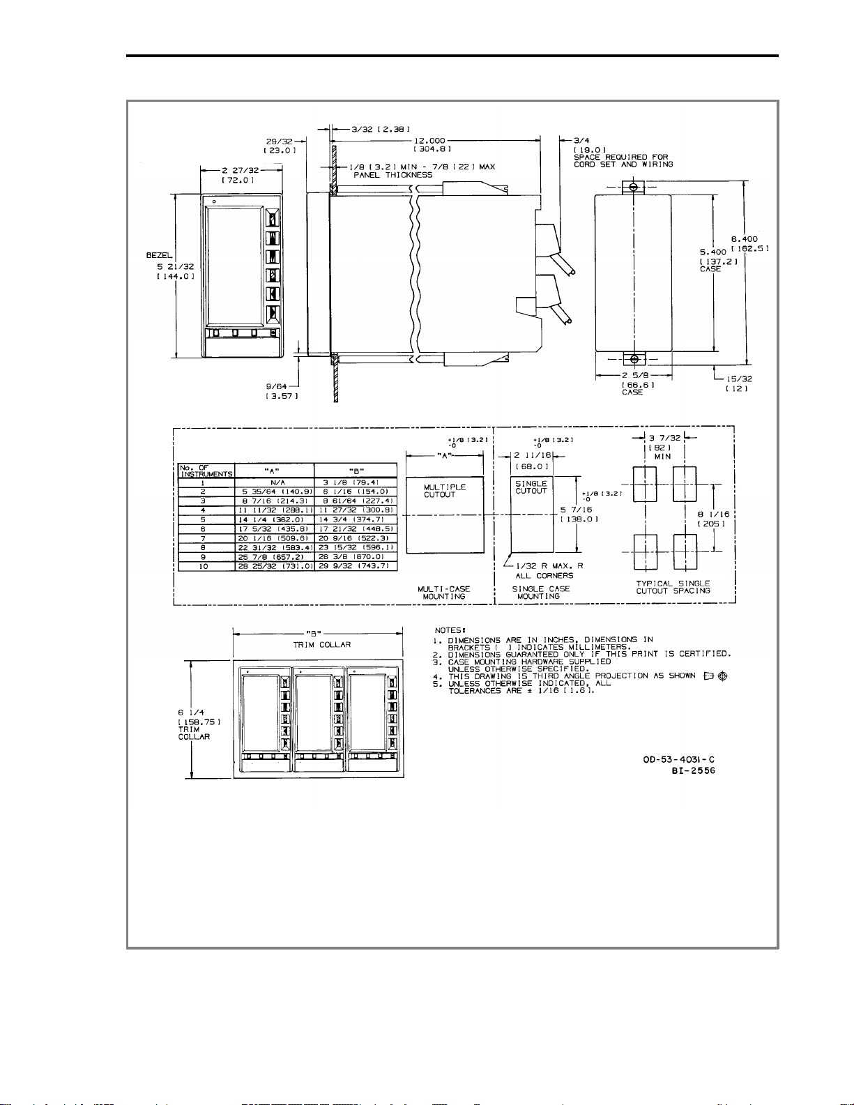
FIGURE 2-1. OUTLINE DIMENSIONS AND PANEL CUT-OUT
REQUIREMENTS
MODULAR CONTROLLER QUICK START
2-3
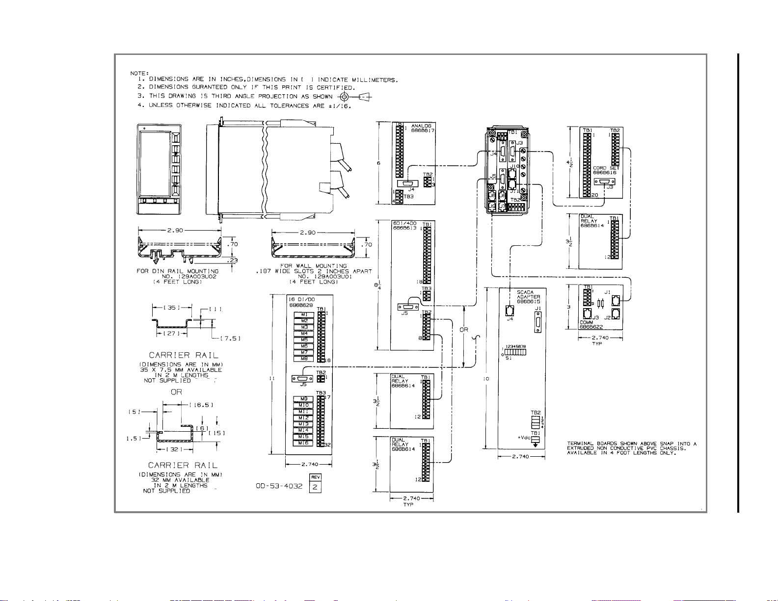
FIGURE 2-2. OUTLINE DIMENSIONS FOR ITB
MODULAR CONTROLLER QUICK START
2-4
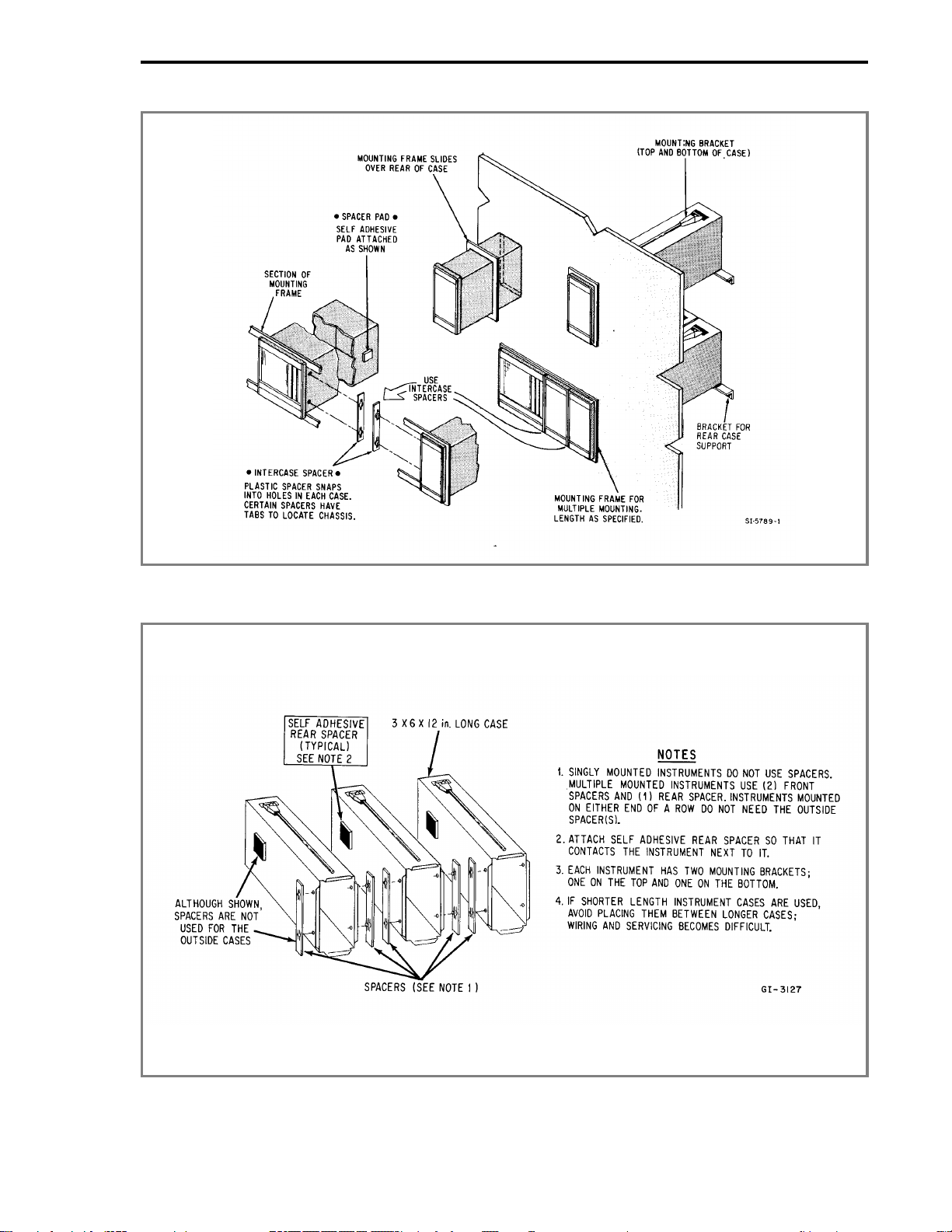
FIGURE 2-3. SINGLE OR MULTIPLE PANEL MOUNTING
FIGURE 2-4. INTERCASE SPACING
MODULAR CONTROLLER QUICK START
2-5

2.4 INTERCONNECTIONS
2.4.1 PREPARATORY
The 53MC5000 can be configured as any of a variety of conventional controller types, enabling it to
be easily adaptable for service in numerous system applications. Prior to electrical interconnection,
the particular instrument configuration should be established and all inputs and outputs identified
and assigned to assure proper signal routing.
2.4.2 WIRING PROCEDURE
Provisions for electrical interconnections are located at the rear of the instrument case. Under ideal
conditions the use of shielded cable may not be required. In noisy locations all system input, out-
put and power wiring should be enclosed in electrical conduit. Rigid conduit should be terminated
by using a short length of flexible conduit at the rear of the case to reduce stress. System intercon-
nection wiring (except for power cable) should be fabricated by the use of 2-wire shielded signal ca-
ble. Signal transmission distance should not exceed the limit specified for the particular transmitter
(refer to applicable technical literature provided for the respective device). Polarity must be ob-
served when connecting the remote transmitters to the Controller.
The Controller is available with integral rear case wiring terminal strips. Power wiring is connected
to separate screw type terminals on the rear of the instrument case. Optional Cord Set connections
are discuss in Section 2.5 of Instruction Bulletin 53MC5000.
NOTE
The screw terminals on the back of the instrument are designed for 12 -
24 AWG wire. It is important that the wire be stripped to expose 1/2 inch
of conductor before installation.
Refer to the Interconnection Diagrams, Figures 2-11 through 2-14 of Instruction Bulletin
53MC5000, to supplement the following description of system interconnections.
WARNING
Instruments that are powered from an ac line service constitute a
potential electric shock hazard to the user. Make certain that these
system ac power lines are disconnected from the operating branch
circuit before attempting electrical interconnections.
2.4.2.1 POWER INPUT (AS SPECIFIED)
2.4.2.1.1 DC Power:
Connect the remote 24 V dc power supply to the Controller, as follows:
1. Connect (+) input line, via remote SPST switch, to terminal "L".
2. Connect (-) input line to the system bus bar. The bus bar should be connected to a good
earth ground (#8 AWG wire is recommended). Individual wires should be run from the Con-
troller Power Common and Signal Common terminals to the bus bar. The chassis should be
grounded by connecting terminal "G" to earth ground.
MODULAR CONTROLLER QUICK START
2-6

NOTE
Use of a common bus bar is recommended to minimize potential voltage
differences that may occur as the result of ground current loops, i.e.,
potential difference between separate signal grounds, power grounds,
etc.
2.4.2.1.2 AC Power:
Connect the specified line service (110-120, 220-240 V ac, 50 or 60 Hz) to the Controller, as
follows:
1. Connect the phase or hot line (L), via a remote power disconnect switch or circuit
breaker, to terminal "L1".
2. Connect the neutral line (N) to terminal "L2" for 110-120 V ac. Connect the neutral line
(N) to terminal "L3" for 220-240 V ac.
3. Connect Power Common to a good earth ground (#12 AWG wire is recommended).
4. The instrument case shall be grounded by connecting terminal "G" to earth ground at the
source of supply (green/green-yellow ground).
5. All supply connections include surge protection rated at 264 V ac, normal mode, and 275
V ac, common mode to chassis ground.
NOTE
To minimize possible interference, ac power wiring should be routed
away from signal wiring.
2.4.2.2 VOLTAGE INPUT
When the input signal is from a 4-20 mA current transmitter, a precision 250 ohms (+/-0.1%) resis-
tor is required. The resistor tolerance is critical in this case, because the resistor is utilized to accu-
rately convert the current signal from the transmitter (4-20 mA, typical) to a specified analog input
voltage (1 to 5 Vdc). The standard rear terminal board has the appropriate resistors on AI0 and
AI1. If the input signal is already a voltage signal, the resistors should be removed. The optional
Cord Set ITB has the appropriate resistors on AI0 - AI3.
2.4.2.3 CONTACT INPUTS
Two separate contact input signals may be used for system sequencing or control purposes, e.g.,
pump "on" contact. One side of each remote contact must be connected to power common, refer to
Figure 2-5 of this manual and Figure 2-11 of the Instruction Bulletin 53MC5000. The remote con-
tact must provide a maintained closure for at least 0.05 second, to provide the Controller with
enough time to "read" the signal. The user must assign each remote contact to a specific input
(DI0-DI1) as dictated by the particular operation to be performed.
2.4.2.4 CURRENT OUTPUT
Two current output signals are available for transmission to remote analog indicating, recording or
controlling devices. The current output signal, 4 to 20 mA, will vary in direct proportion to the proc-
ess variable being displayed, e.g., volumetric flow rate, mass flow rate, operating pressure, etc.
Observe proper polarity when connecting the remote analog instrument.
MODULAR CONTROLLER QUICK START
2-7

2.4.2.5 CONTACT OUTPUTS
Two discrete contact outputs (DO0 to DO1, typically one for each of two separate process measure-
ment loops) are identified in Figures 2-5 and 2-6. The discrete output is a solid state switch with a
rating of 30 V dc, 50 mA maximum. Both discrete outputs are referenced to power common.
The contact outputs are assigned and used in different ways depending on the particular Function
Index being employed.
When these contacts are connected to an inductive load, an external arc suppression network is re-
quired for contact protection.
2.4.3 FACTORY SET CALIBRATION
Each unit contains individual factory set entries which calibrate the standard analog inputs and out-
puts. Upon completion of the installation, the calibration sheet supplied with the instrument should
be retained for future reference.
Refer to Section 6.2 of Instruction Bulletin 53MC5000 for additional information.
MODULAR CONTROLLER QUICK START
2-8
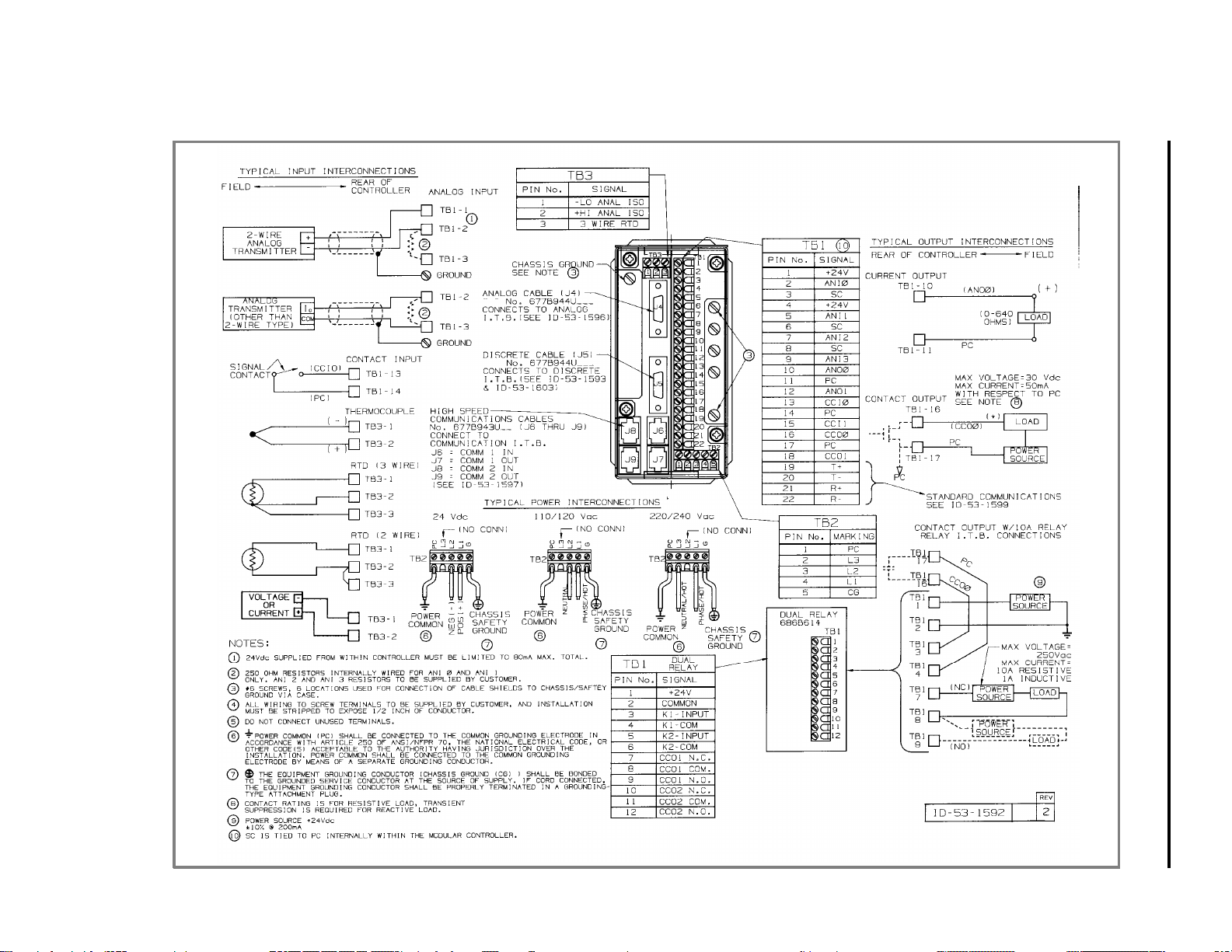
FIGURE 2-5. STANDARD AND OPTIONAL REAR TERMINAL BOARD
MODULAR CONTROLLER QUICK START
2-9
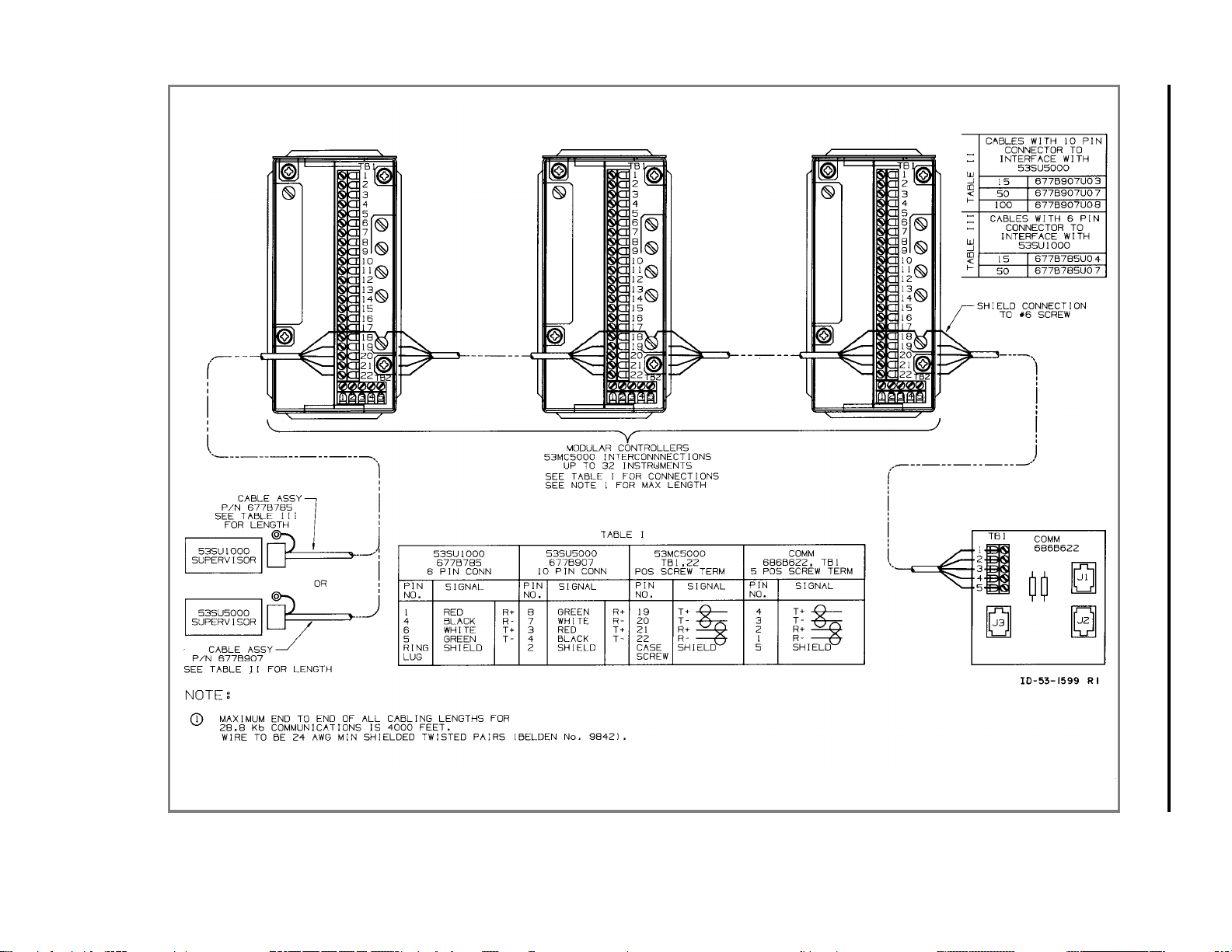
FIGURE 2-6. DATALINK INSTALLATION DIAGRAM FOR STANDARD
REAR TERMINAL BOARD
MODULAR CONTROLLER QUICK START
2-10

2.5 CORD SETS (OPTIONAL)
2.5.1 GENERAL
The 53MC5000 Cord Set receptacle and cables are an alternate method of interconnecting the
Controller to a remotely mounted interconnection terminal block(ITB). The standard instruments
have screw type terminals directly mounted on the rear terminal board. In the cord set version the
screw type terminals and associated circuit board are removed and in its place a circuit board that
terminates in receptacles is furnished.
2.5.2 INSTALLATION
The Cord Set Case is assembled as part of the instrument before leaving the factory. Carefully re-
move the instrument assembly from its packing case. After the instrument has been mounted in the
panel, install the cable or cables. The latches on the plug must engage the receptacle keepers.
2.5.3 INTERCONNECTIONS
The accessory cable and standard lengths are as follows:
1. Signal Cable, standard (20 conductor) - used for control signals, 4AI, 2AO, 2DOs, 2DIs;
standard length 5 feet .
2. Data Link Cable for unit to unit interconnect (6 conductor) - used for connection of one
controller to another; standard length 30 inches with a 6 conductor connector on each end.
3. Refer to Figures 2-7 through 2-9 of this manual and Figures 2-12 through 2-14 of Instruc-
tion Bulletin 53MC5000.
MODULAR CONTROLLER QUICK START
2-11
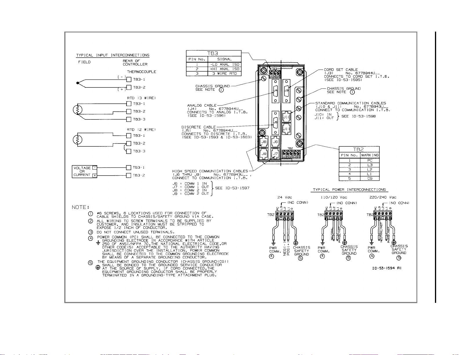
FIGURE 2-7. CORD SET REAR TERMINAL BOARD
MODULAR CONTROLLER QUICK START
2-12
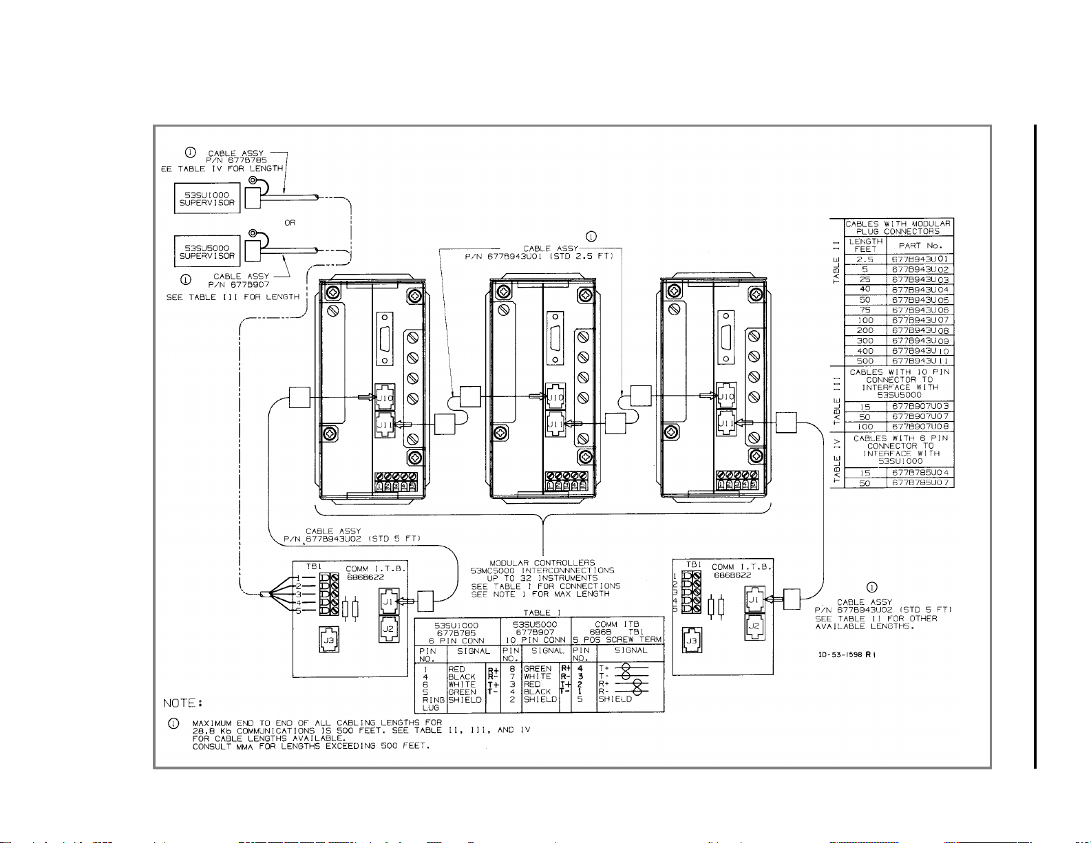
FIGURE 2-8. CORD SET DATALINK INSTALLATION DIAGRAM
MODULAR CONTROLLER QUICK START
2-13
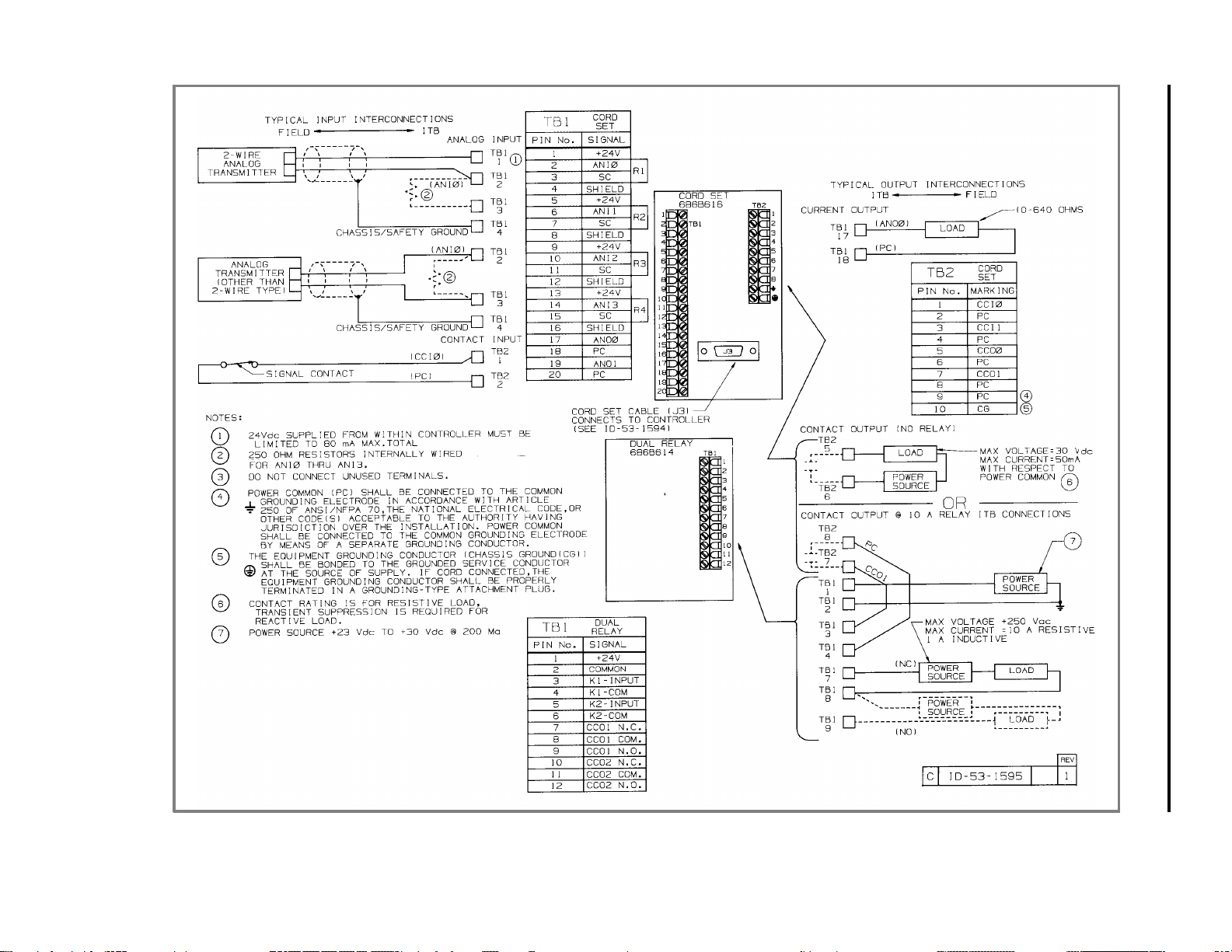
FIGURE 2-9. CORD SET INTERCONNECTION TERMINAL BOARD
MODULAR CONTROLLER QUICK START
2-14

2.6 GROUNDING
Installations are expected to have access to an independent, high quality, noise-free point of earth
reference. The system should be connected by a dedicated, low resistance (less than one ohm)
lead wire directly to the installation’s point of earth reference. This ground reference is referred to
as the Instrumentation Ground. If an instrumentation ground reference does not exist in the installa-
tion, an earth ground electrode should be established with an independent grounding rod or ground-
grid mesh.
MODULAR CONTROLLER QUICK START
2-15

3.0 FUNCTIONALITY
This section provides general instructions for configuring the 53MC5000 Modular Controller for op-
eration, and the information necessary for a quick and easy set-up of the CS-1 Standard PID and
CS-20 Two Loop controller. For special configuration or other Control Strategy types, refer to the
53MC5000 Instruction Manual.
The 53MC5000 controller’s functionality is controlled by the instrument’s Function Index (FIX). The
available FIXs are described below. The FIX is set by means of database parameter B00. As de-
scribed in Section 4.0, when shipped from the factory the Flexible Control Strategy, FIX 1, is en-
abled. The basic FIX 1 control strategy, CS1 described in Section 4.0, is a Single Loop PID
Controller. If this control strategy meets your needs, your controller is ready to use as received. If,
however, minor changes are required such as enabling remote setpoint or characterizing the PV in-
put, follow the instructions provided in Section 4.1 for making these minor modifications. (Note that
all changes made to parameters must be made using one of the methods described in Section
3.2.2)
Instructions for transforming the single-loop Flexible Control Strategy into a direct digital controller,
flow ratio controller, automatic/manual station, or ratio automatic/manual station are provided in the
53MC5000 Instruction Bulletin.
All FIXs are executed in a common environment of input, output and general modules. Each con-
trol strategy mentioned above may be further modified by taking advantage of the standard mod-
ules described in Section 3.5. Customizing the FIX 1 Control Strategy by changing the modules is
described in Section 4.4 of Instruction Bulletin 53MC5000.
If a greater degree of customization is desired, the extended version of the 53MC5000 allows de-
signing of a user-defined control strategy using F-CIM function blocks as described in the
53MC5000 Customization Guide. For the ultimate degree of customization, F-TRAN, also de-
scribed in the Customization Guide, can be used with the extended version of the controller.
The available FIXs are:
FIX 0 - Suspend Control
The control program stops,inputs continue to be measured, and Totalizers and Trends continue to
update. Outputs reflect the contents of their associated datapoints. The display will always show
the Fischer & Porter logo.
FIX 1 - Flexible Control Strategy (FCS)
The FIX 1 control algorithm executes a set of function modules in a fixed sequence. The inputs of
each module can be connected to the output of any other module simply by configuring the appro-
priate database parameter (soft wiring). Various pre-configured wirelists are contained within the
unit and each is referred to as a control strategy (CS). Two of the available control strategies are
explained in the subsequent section. All of the control strategies are defined in Section 4 of Instruc-
tion Bulletin 53MC5000. The controller is shipped with FCS active, FIX = 1, and the standard single
loop control strategy CS = 1 enabled.
MODULAR CONTROLLER QUICK START
3-1

FIX 97 - Display Test
FIX 97 causes a series of three test patterns to appear on the display. One pattern lights the dots
around the outer edge of the display. A second pattern lights the even numbered dots. The third
pattern lights the odd numbered dots. The control program stops but the database is not disturbed..
FIX 98 - Default Database
The database of the controller can be set to a predetermined condition by setting B00 to 98. This
causes the entire database except for the analog I/O calibration constants, the FCS wirelist, and
some text strings ("A" data types) to be set to default values. After this operation, the controller re-
turns to FIX 0. See the tables in Section 7 of Instruction Bulletin 53MC5000 for the default values
of each parameter.
The Extended Functionality version of the Controller allows additional customization through the
use of F-CIM function block programming and F-TRAN programming.
FIX 99 - F-CIM Programming
If a control strategy is needed that can not be accomplished by use of the FCS algorithm, the F-
CIM configuration method can be used. F-CIM allows the soft wiring as in the FCS algorithm and
also allows the use of additional modules and user specified sequencing of the modules. Each mod-
ule constitutes a step and the entire sequence can be 100 steps long. A large library of modules is
available. Many of these are reusable, that is, they can be used as many times as necessary.
FIX 99 is ignored unless the Controller is of the Extended Functionality version which allows addi-
tional customization through the use of F-TRAN.
For the ultimate in flexibility and performance, custom control strategies can be implemented using
the F-TRAN Programming language. It is also possible to create custom modules using the
F-TRAN programing language discussed in the 53MC5000 Customization Guide.
Using the Extended Functionality Option also permits the development of customized controller
strategies and displays using the F-TRAN language. The development and loading of F-TRAN pro-
grams can be performed using the MicroMod Automation Micro-Tools product. .

3.1 CONTROLLER FRONT PANEL
3.1.1 DISPLAY
The Modular Controller contains a high visibility dot matrix display. It is possible to configure static
and/or dynamic data for application to specific displays. A detailed discussion of the various types
of displays can be found in section 4.2 of Instruction Bulletin 53MC5000.
3.1.1.1 ALARM ANNUNCIATION
If a process alarm occurs "ALARM" will begin flashing on the top line of the display. The alarm is
acknowledged by pressing the "MODE" pushbutton
3.1.1.2 ENGINEERING LINE
When the controller is in Engineering Mode described in Section 3.4 of Instruction Bulletin
53MC5000, the bottom line of the display can be used to display or change any of the controllers
parameters.
3.1.2 KEY FUNCTIONS
The operation of the 10 pushbuttons on the front of the controller (see Figure 3-1) depends on the
type of display currently selected. In general, the keys function as described below. Unless speci-
fied as an Engineering Mode function, the functions listed are for control mode.
R/L - This key is used by the POINT and GROUP displays to switch between REMOTE and LOCAL
setpoint modes.
SP Buttons - The setpoint pushbuttons are used to adjust the setpoint of POINT displays and to
highlight various selections in other displays. In Engineering Mode these keys are used to change
or set values.
A/M - This button is used by the POINT displays to switch between AUTOMATIC and MANUAL op-
eration.
OUT Buttons - The output pushbuttons are used by the POINT displays to adjust the output of the
controller when the controller is in manual. In Engineering Mode these keys are used to change or
set values.
MODE Button - The "MODE" button is used to turn off the alarm annunciator. If the alarm annuncia-
tor is not ON when the key is pressed, Engineering Mode is entered. Pressing the MODE key while
in Engineering mode will return the user to normal "Operator Mode".
F1 - The F1 key is normally used to either page back to the previous display or to step to the next
display group depending on how the display hierarchy has been configured. In Engineering Mode
the F1 key moves back to the previous menu level.
F2 - The F2 key is normally used to advance to the next display. In Engineering Mode the F2 key is
used to advance through the various choices (DISPLAY - CONFIGURE - PROGRAM).
F3 - The F3 key is used as an "ENTER" key by the Status, Parameter, and Summary displays to se-
lect the indicated menu choice. In the TWO LOOP display it toggles between the two loops.
In Engineering Mode the F3 key is used as an ENTER to choose the current selection or to com-
plete the entry.
MODULAR CONTROLLER QUICK START
3-3
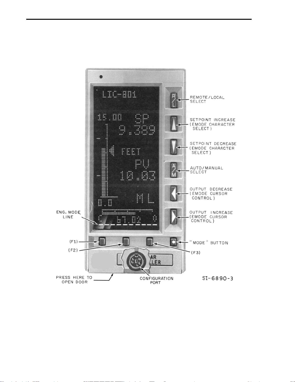
FIGURE 3-1. MODULAR CONTROLLER FRONT PANEL
Note: EMODE = Engineering Mode
MODULAR CONTROLLER QUICK START
3-4
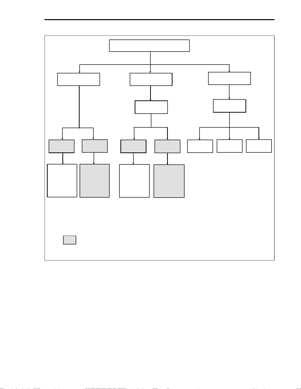
Figure 3-2. Engineer Mode Command Overview
*See 53MC5000 Customization Guide
** If configured
Blocks shown shaded only appear when using the Hi-Resolution display
Engineer Mode
Display Configure
Program *
Key? **
[Sec 3.2.1]
Key? **
[Sec 3.2.1]
Display
Datapoint
Operations
[Sec. 3.2.2]
Module
Datapoint
Configure
Datapoint
Operations
[Sec. 3.2.4]
Module
Datapoint
View
EraseBuild
Module
Display
Mode
[Sec. 3.2.3]
Module
Configure
Mode
[Sec. 3.2.5]
MODULAR CONTROLLER QUICK START
3-5
Loading...