

Page 1
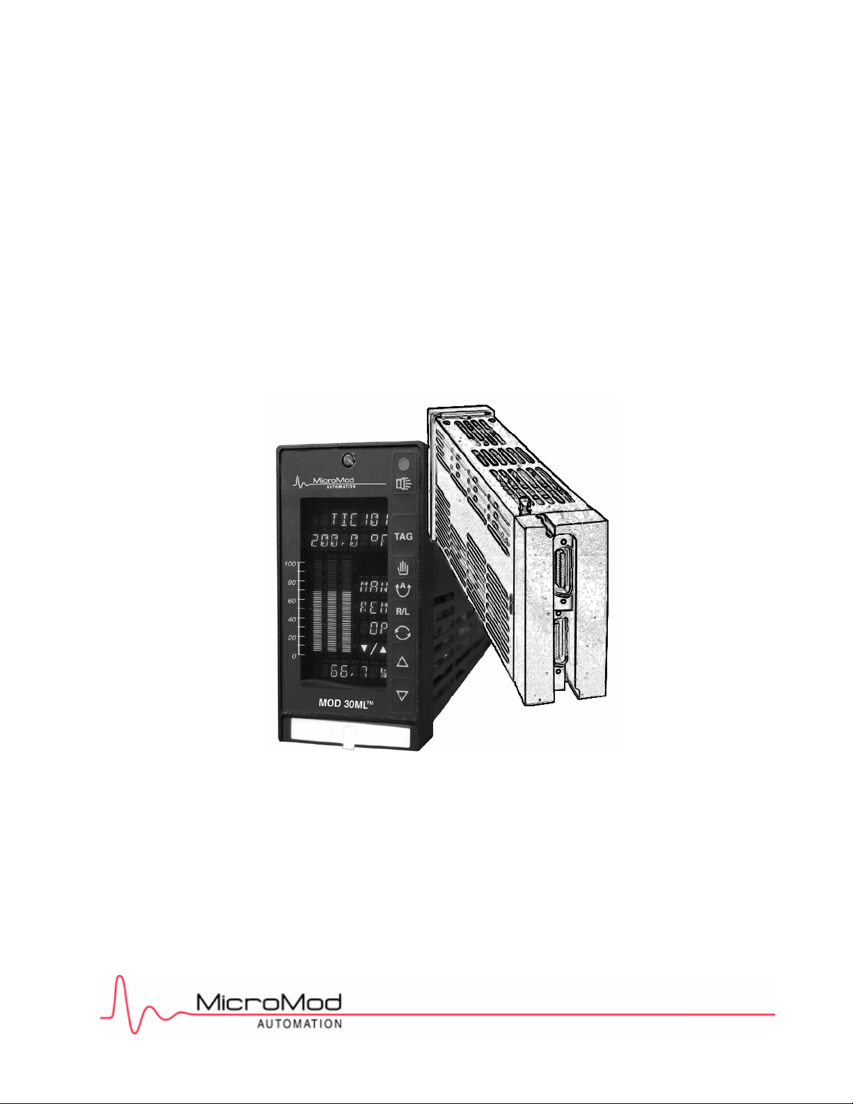
MOD 30ML™ Multiloop Controller Installation
Replacement for MOD 30 Instruments
Product Description, Installation and Wiring for
1800R Model A with MOD 30 Termination Assembly
and Associated Hardware
Page 2
MicroMod Automation, Inc.
The Company
MicroMod Automation is dedicated to improving customer efficiency by providing the most cost-effective, application-specific process solutions
available. We are a highly responsive, application-focused company with years of expertise in control systems design and implementation.
We are committed to teamwork, high quality manufacturing, advanced technology and unrivaled service and support.
The quality, accuracy and performance of the Company's products result from over 100 years experience, combined with a continuous
program of innovative design and development to incorporate the latest technology.
Use of Instructions
Ì Warning. An instruction that draws attention to the risk of
injury or death.
Note. Clarification of an instruction or additional
information.
q Caution. An instruction that draws attention to the risk of
the product, process or surroundings.
Although Warning hazards are related to personal injury, and Caution hazards are associated with equipment or property damage, it
must be understood that operation of damaged equipment could, under certain operational conditions, result in degraded process
system performance leading to personal injury or death. Therefore, comply fully with all Warning and Caution notices.
Information in this manual is intended only to assist our customers in the efficient operation of our equipment. Use of this manual for
any other purpose is specifically prohibited and its contents are not to be reproduced in full or part without prior approval of MicroMod
Automation, Inc.
Licensing, Trademarks and Copyrights
MOD 30 and MOD 30ML are trademarks of MicroMod Automation, Inc.
MODBUS is a trademark of Modicon Inc.
Health and Safety
To ensure that our products are safe and without risk to health, the following points must be noted:
The relevant sections of these instructions must be read carefully before proceeding.
1. Warning Labels on containers and packages must be observed.
2. Installation, operation, maintenance and servicing must only be carried out by suitably trained personnel and in accordance with the information
given or injury or death could result.
3. Normal safety procedures must be taken to avoid the possibility of an accident occurring when operating in conditions of high
4. pressure and/or temperature.
5. Chemicals must be stored away from heat, protected from temperature extremes and powders kept dry. Normal safe handling procedures must be
used.
6. When disposing of chemicals, ensure that no two chemicals are mixed.
Safety advice concerning the use of the equipment described in this manual may be obtained from the Company address on the back
cover, together with servicing and spares information.
i Information. Further reference for more detailed
information or technical details.
All software, including design, appearance, algorithms and source
codes, is copyrighted by MicroMod Automation, inc. and is owned by
MicroMod Automation or its suppliers.
Page 3

MOD 30ML Replacement for MOD 30 Instruments
CONTENTS
––––––––––––––––––––––––––––––––––––––––––––––––––––––––––––––––––––––––––––––––––––––––––––
CONTENTS
Page
SECTION 1 -PRODUCT DESCRIPTION
1.1 OVERVIEW . . . . . . . . . . . . . . . . . . . . . . . . . . . . . . . . . . . . . . . . . . . . . . . . . . . 1
1.1.1 The Product . . . . . . . . . . . . . . . . . . . . . . . . . . . . . . . . . . . . . . . . . . . . . . . . . 1
1.1.2 Related Documents . . . . . . . . . . . . . . . . . . . . . . . . . . . . . . . . . . . . . . . . . . . 3
1.2 EXPLANATION OF CATALOG NUMBERS . . . . . . . . . . . . . . . . . . . . . . . . . . . . . 4
1.3 BASIC HARDWARE . . . . . . . . . . . . . . . . . . . . . . . . . . . . . . . . . . . . . . . . . . . . . 4
1.3.1 1800R With MOD 30 Termination Assembly . . . . . . . . . . . . . . . . . . . . . . . . . . 4
1.3.2 1800P MOD 30ML Identity Module . . . . . . . . . . . . . . . . . . . . . . . . . . . . . . . . . 6
1.3.3 2010P Memory Module . . . . . . . . . . . . . . . . . . . . . . . . . . . . . . . . . . . . . . . . . 6
1.4 I/O MODULES . . . . . . . . . . . . . . . . . . . . . . . . . . . . . . . . . . . . . . . . . . . . . . . . . 7
1.4.1 2001A Voltage Input Module . . . . . . . . . . . . . . . . . . . . . . . . . . . . . . . . . . . . . 7
1.4.2 2006A Nonisolated Digital Input Module . . . . . . . . . . . . . . . . . . . . . . . . . . . . . 8
1.4.3 2007A Nonisolated Digital Output Module . . . . . . . . . . . . . . . . . . . . . . . . . . . 8
1.4.4 2030N ICN Communication Module . . . . . . . . . . . . . . . . . . . . . . . . . . . . . . . . 9
SECTION 2 - PREREPLACEMENT CONSIDERATIONS
2.1 General . . . . . . . . . . . . . . . . . . . . . . . . . . . . . . . . . . . . . . . . . . . . . . . . . . . . 11
2.2 COMMUNICATIONS AND I/O SIGNALS . . . . . . . . . . . . . . . . . . . . . . . . . . . . . . 12
2.2.1 Communications . . . . . . . . . . . . . . . . . . . . . . . . . . . . . . . . . . . . . . . . . . . . . . 12
2.2.2 I/O Signal Availability . . . . . . . . . . . . . . . . . . . . . . . . . . . . . . . . . . . . . . . . . . 12
2.2.3 I/O Signal Specification Differences . . . . . . . . . . . . . . . . . . . . . . . . . . . . . . . . 14
2.3 CONTROLLER . . . . . . . . . . . . . . . . . . . . . . . . . . . . . . . . . . . . . . . . . . . . . . . 14
2.4 INDICATOR . . . . . . . . . . . . . . . . . . . . . . . . . . . . . . . . . . . . . . . . . . . . . . . . . . 16
2.5 MATH UNIT . . . . . . . . . . . . . . . . . . . . . . . . . . . . . . . . . . . . . . . . . . . . . . . . . . 16
SECTION 3 - REPLACEMENT PROCEDURE
3.1 GENERAL . . . . . . . . . . . . . . . . . . . . . . . . . . . . . . . . . . . . . . . . . . . . . . . . . . . 19
3.1.1 Display . . . . . . . . . . . . . . . . . . . . . . . . . . . . . . . . . . . . . . . . . . . . . . . . . . . . 19
3.1.2 Storage . . . . . . . . . . . . . . . . . . . . . . . . . . . . . . . . . . . . . . . . . . . . . . . . . . . 19
3.2 UNPACKING THE REPLACEMENT INSTRUMENT . . . . . . . . . . . . . . . . . . . . . . 19
3.3 INSTALLING MODULES . . . . . . . . . . . . . . . . . . . . . . . . . . . . . . . . . . . . . . . . . 20
3.4 SETTING UP COMMUNICATIONS . . . . . . . . . . . . . . . . . . . . . . . . . . . . . . . . . 21
3.5 REMOVING OLD MOD 30 INSTRUMENT . . . . . . . . . . . . . . . . . . . . . . . . . . . . 22
3.6 INSTALLING NEW MOD 30ML REPLACEMENT INSTRUMENT . . . . . . . . . . . . . 24
3.6.1 Mounting . . . . . . . . . . . . . . . . . . . . . . . . . . . . . . . . . . . . . . . . . . . . . . . . . . 24
3.6.2 Electrical Connections . . . . . . . . . . . . . . . . . . . . . . . . . . . . . . . . . . . . . . . . . 25
APPENDIX A - PLANNING FORMS
i
Page 4

MOD 30ML Replacement for MOD 30 Instruments
CONTENTS
–––––––––––––––––––––––––––––––––––––––––––––––––––––––––––––––––––––––––––––––––––––––––––
ILLUSTRATIONS
Page
1-1 Location of Controller Components . . . . . . . . . . . . . . . . . . . . . . . . . . . . . . . . . . . 2
2-1 Example of an I/O Module Plan for a Controller Replacement . . . . . . . . . . . . . . . . 15
2-2 Example of an I/O Module Plan for a Math Unit Replacement . . . . . . . . . . . . . . . . 17
3-1 Communication Jumper locations . . . . . . . . . . . . . . . . . . . . . . . . . . . . . . . . . . . 21
3-2 Removing Mod 30 Instrument Housing . . . . . . . . . . . . . . . . . . . . . . . . . . . . . . . . 23
3-3 Location of Static Drain Clip on Replacement Instrument . . . . . . . . . . . . . . . . . . . 23
3-4 Cable Connector Locations in Back Cover . . . . . . . . . . . . . . . . . . . . . . . . . . . . . 25
3-5 Identification of Negative Terminals for Analog Input Numbers 3, 4, 5, 6, and Power 26
TABLES
Table Page
2-3 I/O Signals Assigned to Dedicated Locations . . . . . . . . . . . . . . . . . . . . . . . . . . . . 13
2-3 I/O Signals which Share a Module Location - No ICN Module Installed . . . . . . . . . 13
2-3 I/O Signals which Share a Module Location - ICN Module Installed . . . . . . . . . . . . 13
ii
Page 5

1.1 OVERVIEW
1.1.1 The Product
The MOD 30ML Replacement Instrument, Figure 1-1, can be used to replace an installed
MOD 30 instrument, or to expand an existing MOD 30 installation. The replacement is a
microprocessor based instrument which can be configured to perform all the PID,
mathematical, sequencing, and logic functions available in MOD 30 instruments. The front
panel display presents process variable, set-point, output, and other operational data in a
format similar to the MOD 30 instrument displays.
Features of the MOD 30ML replacement instrument are as follows:
MOD 30ML Replacement for MOD 30 Instruments
PRODUCT DESCRIPTION
SECTION 1
PRODUCT DESCRIPTION
• Can be installed in existing MOD 30 bezels or panel cutouts.
• Accepts Mod 30 plug-in cable connections.
• Can match all MOD 30 controller and indicator I/O configurations and many math unit
configurations with a combination of built-in I/O circuits and plug-in I/O modules.
• Communicates on the ICN.
• Front panel data base configuration capability.
• Provides extended data base configuration capability using Application Builder software
running on a personal computer and communicating via the ICN.
• An RS-232 port in the front panel permits easy connection of a portable computer for
data base configuration.
• An optional plug-in memory module provides the same data base backup and data
base transfer function as the MOD 30 memory module.
1
Page 6
MOD 30ML Replacement for MOD 30 Instruments
PRODUCT DESCRIPTION
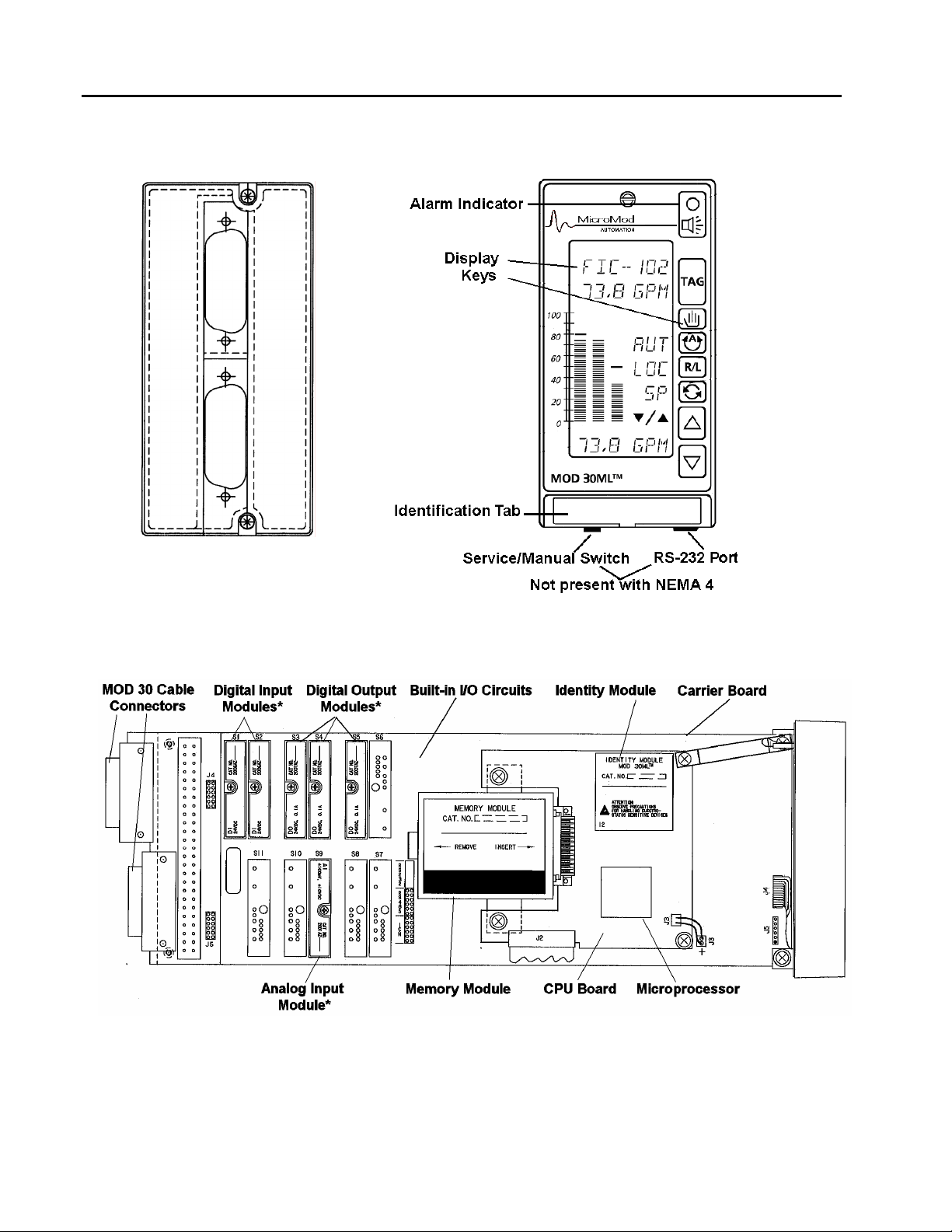
Back of Housing
Front Panel
• These modules are factory
installed when ordering
option package 2.
2
Figure 1-1. Location of Controller Components
Page 7

1.1.2 Related Documents
Instructions on the operation and setup activities performed at the front panel of the
replacement instrument are found in the following document:
• IB-1800R-OPR Operation/Setup, MOD 30ML
Reference information on the data base structure and configuration parameters for the
replacement instrument can be found in the following documents:
• IB-1800R-APP Data Base Reference for MOD 30ML Functions
• IB-23G600 Data Base Reference for System, Logic, I/O and Communication Functions
• IB-23G601 Data Base Reference for Advanced Control Functions
• IB-23G602 Data Base Reference for Algorithms, Sequencers, and Table Functions
• IB-23H141 User’s Guide for Application Builder Software
MOD 30ML Replacement for MOD 30 Instruments
PRODUCT DESCRIPTION
Reference information on ICN/Link communications
following documents.
• IB-23A160 ICN Planning
• IB-23C001 ICN Communication Link Instruction Book for 1720N
• IB-23C003 ICN Mini Link Board Instruction Book for 1731N, 1732N
• IB-23C004 ICN Mini Link External Instruction Book for 1733N, 1732N
The following set of books is supplied as a bound set with the Application Builder Software
for the MOD 30ML:
• 98280-418 MOD 30ML Multiloop Controller User’s Guide
(includes binder, tabs, IB-1800R-INS, IB-1800R-OPR, IB-1800R-APP,
IB-23G600, IB-23G601, IB-23G602 and IB-23A160)
for this instrument can be found in the
3
Page 8

MOD 30ML Replacement for MOD 30 Instruments
PRODUCT DESCRIPTION
1.2 EXPLANATION OF CATALOG NUMBERS
The products described in this book have catalog numbers that help identify specific
features. In addition, some products are assigned a serial number which can be used to
track manufacturing data. The general format of the catalog number is described in this
section. Specific product descriptions are provided in the following sections.
The catalog number stamped on the product data plate contains a series of single and
multiple-character codes. These codes provide specific information concerning various
electrical and/or structural options. Certain code combinations are not allowed, and
options and combinations are subject to change. An example of a typical catalog number
is as follows:
Sample Catalog No. 1800R Z 10 0 2 0 A
Base Number
Unused
Electrical Code
Power
Options
Unused
Model/Design Level
1.3 BASIC HARDWARE
1.3.1 1800R With MOD 30 Termination Assembly.
The 1800R with MOD 30 termination assembly, Figure 1-1, is designed specifically for
replacement of installed MOD 30 instruments, or expansion of existing MOD 30
installations. The replacement instrument mounts in a MOD 30 bezel or panel cutout
using a mounting scheme that is essentially identical to that of the MOD 30 instruments.
Two cable connectors which accept the MOD 30 instrument cables are provided at the
back of the replacement instrument.
4
Page 9

The MOD 30 complement of analog and digital inputs and outputs are supported by a
combination of built-in and modular I/O in the replacement instrument. The built-in circuits
reside on the carrier board and provide two analog inputs and two analog outputs. The
modular I/O circuits are contained in plug-in I/O modules; they provide digital inputs, digital
outputs, and additional analog inputs. The carrier board provides the connection locations for
eleven I/O modules. Thus, a total of 15 I/O points (4 built-in and 11 modular) are available in
the replacement instrument. The modular I/O provides flexibility to vary the mix of digital
inputs, digital outputs, and analog inputs to fit specific replacement requirements. The
parameters of each replacement I/O point can be configured to match the parameters of the
corresponding MOD 30 point. A form of the replacement instrument is available with factory
installed I/O modules. The I/O complement of this form matches the full I/O complement of
the MOD 30 controller and controller XL..
Built-in ICN communications circuitry is provided on the carrier board. When required, the
replacement instrument can communicate on the ICN in the same manner as any MOD 30
instrument. When using a Communications Link to provide data to a personal computer, a
link firmware upgrade may be required to handle some new mnemonics from the
replacement instrument.
The built-in communications circuit can be used to support the RS-232 port in the front panel
instead of the ICN. This provides direct communication with a personal computer for data
base configuration. In this case, ICN communication can be provided by installing a 2030N
ICN Communications Module.
The replacement instrument CPU is based on the 16MHZ 68302 microprocessor. An identity
module (1800P) provides the functionality that gives the instrument the capability to execute
a user-configured database. The CPU supports 64K bytes of nonvolatile RAM for database
storage, and a time-of-day clock with battery support. A high speed communications channel
is used between the CPU and both the built-in I/O and any I/O modules installed on the
instrument. The CPU board provides for connection of a plug-in memory module.
1.3.2 1800P MOD 30ML IDENTITY MODULE
The identity module, Figure 1-1, gives the instrument a specific level of process and
communications functionality. The 1800P module is factory installed and provides the
capability to execute a user-configured database which consists of built-in and modular I/O
handling capabilities, PID functionality, and a collection of other control related functions.
which are available in MOD 30 instruments. These functions reside in a group of basic data
base elements called function blocks.
1.3.3 2010P MEMORY MODULE
The optional memory module plugs directly into the CPU board, Figure 1-1, and provides a
mechanism for porting a database from one replacement instrument to another. An
instrument with this option can upload from or download to this module. The memory module
has a write protect setting to prevent accidental erasures. When a memory module is
installed in an instrument with the write protection off, the operating software keeps the
module up-to-date with all real time changes in the instrument. Enhanced security is thereby
provided through this backup database copy. Data retention is more than 10 years with
instrument un-powered.
MOD 30ML Replacement for MOD 30 Instruments
PRODUCT DESCRIPTION
5
Page 10
MOD 30ML Replacement for MOD 30 Instruments
PRODUCT DESCRIPTION
Catalog Number Description for 1800R MOD 30 Retropak
MOD30 RETROPAK
Base Controller 1800RZ
Approvals
General Purpose 10
CE (European Community
destinations only) 12
Power Supply
24V dc 0
I/O Options - see Note 1
Standard I/O only (two universal 1
analog inputs, two current outputs)
Pre-installed I/O modules 2
(one additional analog input, 2 digital
inputs, 3 digital outputs)
Standard I/O only, NEMA 4, conformal coating 5
Not Used 0
Design Model
General Purpose, FM/CSA approval A
European Approval (CE Certification - B
for European Community destinations)
Programming / Special Features - see Note 2
None S T D
Configured to customer's MOD 30 specifications M 3 0
ACCESSORIES
ICN Termination Assembly (1 per ICN network) 2030FZ00001A
Portable Memory Module (optional) 2010PZ10000A
Upgrade to Version 2 Identity Module 1800PZ10102C
Housing & termination assembly only 1800FZ00002A
(no instrument) - MOD 30 conversion
Output Holder / Manual Loader (see S-MOD-1750N)
Configuration Software Visual Application
Designer - Refer to P-CS-MOD-Vizapp
Note 1: Pre-installed modules match MOD 30 1701R I/O. Other I/O combinations may be ordered by using
Standard I/O option and selecting additional modules from P-MOD-MODULES
____ __ __ __ __ __- __ __ __
0-6 07-08 09 10 11 12 13 14 15
1750NZ10001A
6
Note 2: Customer must provide existing database files and documentation. Excludes 1710R/1711R Sequence
and Logic Unit.
Page 11

1.4 I/O MODULES
The descriptions included in this section give a brief overview of the functions and
features of the I/O modules which can be used in a replacement instrument..
1.4.1 2001A Voltage Input Module
The voltage input module provides dual ranges of ±10V dc and ±100 mV dc. The 10V
dc range can be selected and scaled for 1 to 5 V dc by configuration to match the input of
MOD 30 instruments. Input to the module is scaled and then applied to an integrating
analog to digital converter. Line cycle integration can be performed at integrals of either 50
or 60 Hz line frequencies to reject any line frequency noise. Transformer isolation from
the +5 volt supply is used to derive all the internal voltages to run the isolated front end.
Optical isolation is used to transfer the information from the A/D converter serially to the
microprocessor. The microprocessor takes the raw A/D voltage, compares it to the
reference, and then presents it to the host as requested over the serial communications
bus. This module uses the Voltage/Current Input Module (VCIM) Block for configuration of
input parameters. The default configuration of this block provides the 1 to 5 V dc input
range.
VCIM
1
2
6
7
3
4
5
Catalog Number Description for 2001A
BASE NUMBER 2001A Voltage Input Module
UNUSED Z Unused Character
ELECTRICAL CODE 10 General Purpose, Kent-Taylor standard
MOD 30ML Replacement for MOD 30 Instruments
PRODUCT DESCRIPTION
INPUT RANGE 10 ±100 mV or ±10 Vdc
ISOLATION 1 Isolated
MODEL A Design Level
Sample Number 2001AZ10101A
7
Page 12

MOD 30ML Replacement for MOD 30 Instruments
PRODUCT DESCRIPTION
1.4.2 2006A Nonisolated Digital Input Module
The Nonisolated Digital Input Module accepts switch contact closures without external
power requirements. It is functionally equivalent to a digital input circuit in a MOD 30
instrument. This module uses the Digital Input Module (DIM) Block for configuration of
input parameters.
DIM
1
2
3
4
5
Catalog Number Description for 2006A
BASE NUMBER 2006A Nonisolated Digital Input Module
UNUSED Z Unused Character
ELECTRICAL CODE 10 General Purpose, Kent-Taylor standard
INPUT RANGE 10 2.2 V to 24 VDC
UNUSED 0 Unused Character
MODEL A Design Level
Sample Number 2006AZ10100A
1.4.3 2007A Nonisolated Digital Output Module
The Nonisolated Digital Output Module is primarily intended for instrument-to-instrument
signaling. The module interfaces 24-volt on/off signals with no isolation or works as an
open collector switch that also supports 5V TTL. This module uses the Digital Output
Module (DOM) Block for configuration of output parameters.
DOM
1
2
3
4
5
Catalog Number Description for 2007A
BASE NUMBER 2007A Nonisolated Digital Output Module
UNUSED Z Unused Character
ELECTRICAL CODE 10 General Purpose, Kent-Taylor standard
OUTPUT RANGE 10 24 V, 50 mA TTL
UNUSED 0 Unused Character
MODEL A Design Level
Sample Number 2007AZ10100A
8
Page 13

1.4.4 2030N ICN Communication Module
The ICN Communication module provides Instrument Communication Network (ICN)
communications capability for the instrument when the built-in communications circuit is
used to support the RS-232 communications port on the instrument front panel. The ICN
is a proprietary network that allows peer-to-peer communications between the
replacement instrument and MOD 30 Instruments. It also uses a communication link to a
computer running the Application Builder, or PC-30 Series Software or other operator
interface software. The ICN Baud rate is 31,250 bits per second. The Model B ICN
requires an external ICN terminator such as the 2030F ICN Terminator.
ICN
Catalog Number Description for 2030N
13
1
BASE NUMBER 2030N ICN Communication Module
14
2
6
8
7
9
3
10
11
4
12
5
UNUSED Z Unused Character
15
ELECTRICAL CODE 10 General Purpose, Kent-Taylor standard
16
17
UNUSED 000 Unused Character
MOD 30ML Replacement for MOD 30 Instruments
PRODUCT DESCRIPTION
MODEL A Design Level (includes termination relay)
B Design Level (removes termination relay)
Sample Number 2030NZ10000B
9
Page 14

MOD 30ML Replacement for MOD 30 Instruments
PRODUCT DESCRIPTION
10
Page 15

2.1 GENERAL
This section provides information for planning the replacement of installed MOD 30
instruments using the MOD 30ML Replacement Instrument. The principal factors to be
considered when making a replacement are as follows:
• The replacement applies to the instruments only. Most MOD 30 associated equipment
• A single MOD 30ML instrument (Catalog No. 1800R) is used to replace any MOD 30
• Two forms of the replacement instrument are available:
MOD 30ML Replacement for MOD 30 Instruments
REPLACEMENT CONSIDERATIONS
SECTION 2
REPLACEMENT CONSIDERATIONS
such as termination panels, field input boards, power supplies, etc. are required for
operation of the replacement instrument.
Controller, Controller XL, Indicator, Math Unit or Sequence and Logic Unit.
- Catalog No. 1800RZ_ _ _1_A is supplied without I/O modules. The user must
specify the modules required for the specific application, and install the modules
as part of the replacement procedure.
- Catalog No. 1800RZ_ _ _2_A is supplied with factory installed I/O modules to
fully match the I/O complement of the 1700R and 1701R controllers.
• The maximum possible I/O count for a MOD 30 instrument using both cables (i.e., a
1700N Math Unit) is 22 points. The maximum possible I/O count for the MOD 30ML is
15 points of which 11 points are provided by plug-in I/O modules. The modular nature
of these 11 points provides I/O flexibility to cover many replacement requirements.
• Some I/O module locations in the MOD 30ML can accept either an analog or digital
signal. When these locations are used for digital inputs, the corresponding analog input
negative terminal must be grounded to the power supply negative at the termination
panel (specific connection instructions are provided in Section 3).
• The output holder used with the MOD 30 controllers is not supported by the
replacement instrument.
• The replacement instrument is an indicating device; it cannot replace the MOD 30
recorder.
• If it is necessary to obtain both ICN communication and RS-232 communication for
data base configuration via the port in the front panel, a 2030N ICN module must be
installed.
• After completing installation of a replacement instrument, its data base must be
configured to match the functional requirements of the application. Configuration
information is provided in other documents; see Section 1.1.2.
11
Page 16

MOD 30ML Replacement for MOD 30 Instruments
REPLACEMENT CONSIDERATIONS
2.2 COMMUNICATIONS AND I/O SIGNALS
2.2.1 COMMUNICATIONS
A built-in communications circuit supports either the RS-232 port in the front panel or
communication over the ICN. If the built-in circuit is used for the RS-232 port, an ICN
module must be installed to support ICN communication. The communication options
are selected by positioning two jumpers. Specific instructions for locating the jumpers
are provided in Section 3.4.
Selection of the jumper positions is based on one of the following requirements:
•
Both ICN and RS-232 communication is required
provide modular ICN communication, and RS-232 communication via the built-in
circuit. A 2030N ICN Communications module must be installed in module
locations S7 and S8 to support the ICN. Note that use of this module reduces the
number of I/O signals which can be accepted as shown in Tables 2-2 and 2-3.
- The jumpers are located to
•
Only ICN communication is required
communication via the built-in circuit. Installation of an ICN module is not required.
The RS-232 port is not active.
•
Only RS-232 communication is required
232 communication via the built-in circuit. Installation of an ICN module is not
required because the ICN is not being used.
2.2.2 I/O Signal Availability
The I/O points available in the replacement instrument are distributed between built-in and
modular circuits as follows:
• Built-in circuits provide 4 points; 2 analog inputs, 2 analog outputs.
• I/O Modules provide the following points:
- 3 module locations are dedicated to digital input numbers 1, 2, and 3.
- 4 module locations are dedicated to digital output numbers 1, 2, 3, and 4.
- When the built-in communications circuit is used for the ICN, 4 module locations
can be used for analog inputs, digital inputs or digital outputs on a shared basis.
- When a communications module is used for the ICN, 2 module locations can be
used for analog inputs, digital inputs or digital outputs on a shared basis.
- The jumpers are located to provide ICN
- The jumpers are located to provide RS-
12
The MOD 30 I/O signals which are assigned to a specific I/O module or built-in circuit are
identified in Table 2-1. The signals which share assignment to an I/O module location with
1 or 2 other signals are as identified in Tables 2-2 and 2-3. The user must select one
shared signal for each module depending on the requirements of the application. As
shown in Table 2-3, the modules available to accept shared signals is reduced when an
ICN module is used.
Page 17

MOD 30ML Replacement for MOD 30 Instruments
REPLACEMENT CONSIDERATIONS
Table 2-1. I/O Signals Assigned to Dedicated Locations
Signal Location
Digital Input No. 1 Module Location S1
Digital Input No. 2 Module Location S2
Digital Input No. 3 Module Location S11
Digital Output No. 1 Module Location S3
Digital Output No. 2 Module Location S4
Digital Output No. 3 Module Location S5
Digital Output No. 4 Module Location S6
Analog Input No. 1 Built-in Volt Input No. 1
Analog Input No. 2 Built-in Volt Input No. 2
Analog Output No. 1 Built-in milliamp Output No. 1
Analog Output No. 2 Built-in milliamp Output No. 2
Table 2-2. I/O Signals Which Share a Module Location - No ICN Module Installed
Communications
//////// No. 5 No. 7 ////// Location S7
//////// No. 6 No. 6 No. 7 Location S8
//////// No. 3 No. 5 No. 6 Location S9
//////// No. 4 No. 4 No. 5 Location S10
Built-in ICN //////// //////// //////// ////////
Analog
Input
Digital
Input
Digital
Output
I/O Module
Location
Table 2-3. I/O Signals Which Share a Module Location - ICN Module Installed
Communications Analog
Input
ICN Module //////// //////// //////// Locations S7&S8
//////// No. 3 No. 5 No. 6 Location S9
//////// No. 4 No. 4 No. 5 Location S10
RS-232 Port //////// //////// //////// ////////
Digital
Input
Digital
Output
I/O Module
Location
13
Page 18

MOD 30ML Replacement for MOD 30 Instruments
REPLACEMENT CONSIDERATIONS
2.2.3 I/O Signal Specification Differences
In general the specifications for the replacement instrument are compatible with the MOD
30 instrument specifications. The following differences should be noted:
Specification MOD 30 Replacement
Current Requirements
Controller 0.55A max 0.63A max
Indicator 0.50A max 0.63A max
Math Unit 0.58A max 0.63A max
Digital input
High Level (Logic 1) 4.0V dc min 2.2V dc min
Low Level (Logic 0) 1.5V dc max 0.65V dc max
current load 3mA 2.5mA max
Digital Output
Voltage 30V dc max 24V dc max
Current 50mA max 100mA dc max
2.3 CONTROLLERS
The MOD 30 Controller and Controller XL require a single interconnecting cable to carry
power, ICN communication, and I/O signals between the instrument and the termination
panel. The replacement instrument uses this same cable. The full complement of 10 I/O
points and one communications point can be accommodated by the replacement
instrument. The controller I/O signals are as follows:
• 3 Analog Inputs
• 2 Analog Outputs
• 2 Digital Inputs
• 3 Digital Outputs
If the full I/O complement is required, the replacement instrument with factory installed I/O
modules (Catalog No. 1800RZ_ _ _2_A) should be used. The locations of the factory
installed modules, their catalog numbers, and I/O signals are shown on the planning form,
Figure 2-1. This form of the instrument simplifies the replacement procedure because the
user does not need to plan for and specify the required modules, and install the modules
when making the replacement.
If the full I/O complement is not required, the required I/O modules must be selected and
installed when making the replacement. Use the controller I/O module planning form to
record the selected modules and their locations. An example of the form filled in for a
controller having one digital input and 2 digital outputs is shown in Figure 2-1. Note that an
ICN communications module is specified so that both ICN and RS-232 communication are
supported (see Section 2.2.1). See Appendix A for a blank copy of the planning form.
14
Page 19

MOD 30ML Replacement for MOD 30 Instruments
PRODUCT DESCRIPTION
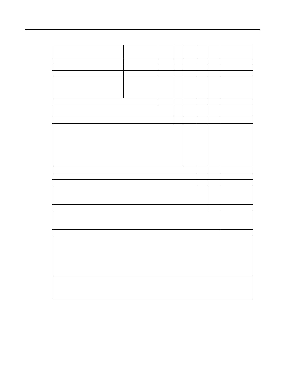
I/O MODULE PLANNING FORM FOR MOD 30 CONTROLLER
MOD 30ML Replacement for Controller No. FIC-102
Signal
Digital Input No. 1 S1 2006A
Digital Input No. 2 S2 2006A
Digital Output No. 1 S3 2007A
Digital Output No. 2 S4 2007A
Digital Output No. 3 S5 2007A
Analog Input No. 3 S9 2001A
Analog Input No. 1 & 2 Built-in
Analog Output No. 1 & 2 Built-in
Built-in Communication Built-in
ICN Module S7 & S8 2030N
I/O Module
Location
I/O Module
Catalog
No.
Module
Package*
(option 2)
////////// //////////
////////// //////////
//////////
No Module
Package
(check if
used)
X
X
X
X
RS-232
X
* Factory installed package.
Note: Locations S6, S10 and S11 are not used for a controller.
Figure 2-1 Example of an I/O Planning Form for a Controller Replacement
15
Page 20

MOD 30ML Replacement for MOD 30 Instruments
REPLACEMENT CONSIDERATIONS
2.4 INDICATOR
The MOD 30 indicator requires a single interconnecting cable to carry power and I/O
signals between the instrument and the termination panel. The replacement instrument
uses this same cable. The full complement of 5 I/O points can be accommodated by the
replacement instrument. The I/O signals are as follows:
• 3 Analog Inputs
• 3 Digital Outputs (Model B only)
The replacement instrument accepts analog inputs No. 1 and No. 2 via built-in input
circuits 1 and 2 as indicated in Table 2-1. An analog input module (Catalog No. 2001A)
must be installed in location S4 to provide the third analog input. Digital output modules
(2007A) must be installed in locations S3, S4 and S5 to provide digital outputs No. 1,
No. 2, and No. 3.
Since the MOD 30 Indicator does not communicate over the ICN, the replacement
instrument must be configured via the RS-232 port in the front panel (see Section 2.2.1).
2.5 MATH UNIT
The MOD 30 math unit requires two interconnecting cables to carry power, ICN
communication, and I/O signals between the instrument and the termination panel. The
replacement instrument uses both of these cables. The full I/O complement for the math
unit is as follows:
• 6 Analog Inputs
• 2 Analog Outputs
• 7 Digital Inputs
• 7 Digital Outputs
The 22 I/O points available in a math unit are not fully covered by the replacement
instrument which can accommodate only 15 I/O points. The combination of built-in and
modular I/O in the replacement instrument does accommodate many math unit I/O
combinations. For example, a possible arrangement using all 15 available points can
provide an I/O combination as follows:
• 4 Analog Inputs
• 2 Analog Outputs
• 5 Digital Inputs
• 4 Digital Outputs
16
In this example, 2 analog inputs and 2 analog outputs are accommodated by the built-in
I/O circuits. The remaining 11 points are handled by the modular I/O.
Use the Math Unit I/O planning form to record the required modules and their locations for
a specific application. An example of the form filled in to document the above example is
shown in Figure 2-2. Note that the built-in circuit is specified for the ICN so that all module
locations are available for I/O signals (see Section 2.2.1). See Appendix A for a blank
copy of the planning form.
Page 21

MOD 30ML Replacement for MOD 30 Instruments
PRODUCT DESCRIPTION
I/O MODULE PLANNING FORM FOR MOD 30 MATH UNIT
MOD 30ML Replacement for Controller No. FIC-101
Signal
Digital Input No. 1 S1 2006A
Digital Input No. 2 S2 2006A
Digital Input No. 11 S2 2006A
Digital Output No. 1 S3 2007A
Digital Output No. 2 S4 2007A
Digital Output No. 3 S5 2007A
Digital Output No. 4 S6 2007A
Analog Input No. 1 & 2 Built-in Volt Input ////////// //////////
Analog Output No. 1 & 2 Built-in mA Output ////////// //////////
Built-in Communication Built-in
ICN Module S7 & S8 2030N
I/O Module
Location
I/O Module
Catalog No.
Module Package*
(option 2)
//////////
No Module
Package (check if
used)
X
X
X
X
X
X
X
ICN
Communication
X No. 3* No. 7 /////
Using Builtin Circuit
Using ICN
Module
* Factory
installed
package
( ) Analog
Input
X No. 4 No. 6 No. 7
No. 5 X No. 5 No. 6
No. 6 X No. 4 No. 5
No. 3* No. 5 No. 6
No. 4 No. 4 No. 5
( ) Digital
Input
( ) Digital
Output
Module
Location
S7
S8
S9
S10
S9
S10
I/O Module
Catalog No.
2001A
2001A
2006A
2006A
Figure 2-2 Example of an I/O Planning Form for a Math Unit Replacement
17
Page 22

MOD 30ML Replacement for MOD 30 Instruments
REPLACEMENT CONSIDERATIONS
18
Page 23

3.1 GENERAL
Read these instructions thoroughly before starting this procedure. Installation personnel
should be qualified technicians.
The replacement procedure involves:
• Unpacking the replacement instrument (Section 3.2)
• Installing I/O modules and optional memory module if used (Section 3.3)
• Setting up communications (Section 3.4)
• Removing the old MOD 30 instrument(Section 3.5)
• Installing the new replacement instrument (Section 3.6)
MOD 30ML Replacement for MOD 30 Instruments
REPLACEMENT PROCEDURE
SECTION 3
REPLACEMENT PROCEDURE
3.1.1 Display
The display is protected by an overlay that can be removed after installation. The face of the
display, while made of scratch-resistant plastic, can be abraded by harsh materials such as paper
towels and industrial wipes. Lens cleaning tissues and soft cloths are suitable for cleaning displays.
3.1.2 Storage
The ambient temperature for any equipment kept in storage must be between –40 and+75°C (–40
and 167
°F)
3.2 UNPACKING THE REPLACEMENT INSTRUMENT
Unpack and visually inspect the instrument housing, instrument, and associated modules
for any damage. Save packing materials for any reshipment, or to support any claim of
shipment damage. All damage claims are made against the carrier and are the
responsibility of the customer.
Included in the shipping container is a bag containing the following items:
• Mounting brackets and retaining screws
• Static drain clip
• Cable connector mounting screws
• Information package
Instructions for assembly of the mounting bracket, static drain clip, and cable connector
mounting screws are provided in Section 3.6.1. The information package includes a card
containing several copies of a writeable instrument identification tag. Write required data
on the tag and insert it under the translucent strip at the bottom of the front panel after the
replacement instrument is installed.
19
Page 24

MOD 30ML Replacement for MOD 30 Instruments
REPLACEMENT PROCEDURE
3.3 INSTALLING MODULES
The I/O modules mount on the carrier board, and the optional memory module mounts on
the processor board as shown in Figure 1-1. The I/O modules must be installed before
placing the controller into operation.
Each I/O module must be installed in a location which receives or transmits the
appropriate MOD 30 signal. The following procedure is based on the assumption that the
number of modules, the module types, and the location of each module has been
determined as described in Section 2.
* NOTE:
Install the modules as follows:
1. Loosen the 2 retaining screws in the front panel, Figure 1-1, and pull the
instrument out of its housing.
! CAUTION
If a MOD 30 controller is being replaced by the MOD 30ML Replacement
Instrument with factory installed I/O (Catalog No. 1800R Z___2_A), this
procedure is not required. Proceed to Section 3.4.
Support the instrument from the front and bottom or from the insulator
plate whenever the instrument is outside its housing. Do not allow the full
weight of the circuit boards to be suspended unsupported from the front
panel as this may overstress the brackets at that end.
2. Place the instrument on a flat surface with the front panel overhanging the
edge of the surface so that the black insulator plate is firmly supported. This
positioning assures that the instrument is not damaged by the force applied
when inserting I/O modules.
3. Plug each I/O module into its required location on the carrier board and
tighten the retaining screw.
4. If the optional memory module is being used, it can be plugged into the
location provided on the CPU board.
5. If ICN or RS-232 communication is to be used, go to Section 3.4, otherwise
continue with Step 6.
6. Insert the instrument into its housing and tighten the screws to draw the front
panel tight against the housing.
3.4 SETTING UP COMMUNICATIONS
Use this procedure to make the required communications available. See Section 2.2.1 for
detailed information about communication options.
1. If the instrument is in its housing, loosen the 2 retaining screws in the front panel,
Figure 1-1, and pull the instrument out of the housing.
2. If a 2030N ICN Communications module is required, install the module in locations S7
and S8 using the procedure described in Section 3.3
20
Page 25

MOD 30ML Replacement for MOD 30 Instruments
REPLACEMENT PROCEDURE
3. Position the communication jumpers, Figure3-1, as follows:
• If an ICN Module is installed, place the jumpers as shown for ICN and RS-232.
• If the ICN is to use the built-in communication circuit (no ICN module), place the
jumpers as shown for ICN ONLY.
• If the ICN is not being used, place the jumpers as shown for RS-232 ONLY.
4. Insert the instrument into its housing and tighten the screws to draw the front panel tight
against the housing.
Communication Jumper Locations
ICN & RS-232 ICN Only RS-232 Only
21
Page 26

MOD 30ML Replacement for MOD 30 Instruments
REPLACEMENT PROCEDURE
3.5 REMOVING OLD MOD 30 INSTRUMENT
The replacement instrument uses the cables in the existing installation. If there is a MOD
30 instrument installed in the location planned for the replacement, remove the MOD 30
instrument and its housing as follows:
1. Be sure the process is in a safe condition before removing the instrument.
2. Pull the MOD 30 instrument out of its housing.
3. Remove the back cover, Figure 3-2, from the housing.
4. Disconnect the drain wire from the static drain clip. If the drain wire is
connected to other MOD 30 instruments which are to remain installed, the
wire must remain in place to connect each of these instruments together and
to ground.
5. Remove the cable mounting screws to disconnect the cable(s) from the back
cover.
6. Loosen the retaining screws and remove mounting brackets from the top and
bottom of the housing.
7. From the front of the panel, remove the housing.
22
Page 27

MOD 30ML Replacement for MOD 30 Instruments
REPLACEMENT PROCEDURE
Figure 3-2. Removing MOD 30 Instrument Housing
Figure 3-3. Location of Static Drain Clip On Replacement Instrument
23
Page 28

MOD 30ML Replacement for MOD 30 Instruments
REPLACEMENT PROCEDURE
3.6 INSTALLING NEW MOD 30ML REPLACEMENT INSTRUMENT
After removing a MOD 30 instrument, the replacement instrument can be installed
in the same panel or bezel opening and connected to the existing MOD 30 cables
using the following procedures.
3.6.1 Mounting
1. If the replacement instrument is not in its housing, insert the instrument and
2
. From the front of the panel, insert the instrument into the panel or bezel
3. From the back of the panel, insert mounting brackets into the slots in the
4. Tighten retaining screws to hold instrument in place. Use torque of 5 inch-
5
. Remove the back cover from the mounted instrument and install the static
tighten the screws to draw the front panel tight against the housing. It is
recommended that the housing be mounted with the instrument installed.
This improves the housing rigidity and helps prevent the possibility of
distortion when the mounting screws are tightened.
opening.
top and bottom of the housing
pounds (0.6 Nm), or turn each screw 1-1/2 turns after contact is made with
the back of the panel.
drain clip on the back of the housing (the clip is supplied with the
instrument). Locate the clip near the upper right corner as shown in Figure
3-3. This location aligns the clip with a recess in the back cover allowing
the cover to seat properly against the back of the housing with the clip
installed.
.
24
6
. Connect the MOD 30 J1 cable to the J1 location in the back cover, Figure
3-4. The cable is attached to the cover using two mounting screws as
shown in Figure 3-2 (cable mounting screws are supplied with the
instrument). Two cables are used when a math unit is replaced; connect
the second cable to location J2
7. Mount the back cover with attached cable on the instrument housing. The
cable connectors must mate with the connectors on the instrument circuit
.
board
8. Connect the existing drain wire to the static drain clip on the back of the
replacement instrument. The drain wire must connect the replacement
instrument to all other instruments and to ground.
.
Page 29

MOD 30ML Replacement for MOD 30 Instruments
REPLACEMENT PROCEDURE
J1
J2
Figure 3-4. Cable Connector Locations In Back Cover
3.6.2 Electrical Connections
The required power, ICN communication, and I/O signal connections to the replacement
instrument are made via the cables which are installed as part of the mounting procedure.
! CAUTION
The negative analog and power terminals are identified in Figure 3-5. The required
connections are as follows:
• To use module location S7 for a digital signal, ground Analog Input 5 negative.
• To use module location S8 for a digital signal, ground Analog Input 6 negative.
• To use module location S9 for a digital signal, ground Analog Input 3 negative.
• To use module location S10 for a digital signal, ground Analog Input 4 negative.
* NOTE:
If I/O module location S7, S8, S9, or S10 is used for a digital input or
output, the negative terminal of the alternate analog signal which can use
the location must be grounded to the negative power supply terminal at
the termination panel, and the positive terminal of the analog signal must
be open circuited.
Before putting the instrument into operation, it must be configured using either
the front panel keys or the 2006S Application Builder software. See Section
1.1.2 for related documents.
25
Page 30

MOD 30ML Replacement for MOD 30 Instruments
REPLACEMENT PROCEDURE
Power
Analog
Input No. 3
Analog
Input No. 4
Analog
Input No. 5
Analog
Input No. 6
1720F Termination Panel Section
Connected to J1 on Instrument
1720F Termination Panel Section
Connected to J2 on Instrument
Figure 3-5. Identification of Negative Terminals for Analog Input Numbers 3, 4, 5, 6, and Power
26
Page 31

A.1 GENERAL
The forms included in this appendix may be copied as necessary to record the I/O module
layout for MOD 30ML replacement instruments used to replace MOD 30 controllers and
math units.
MOD 30ML Replacement for MOD 30 Instruments
APPENDIX A
APPENDIX A
PLANNING FORMS
27
Page 32

MOD 30ML Replacement for MOD 30 Instruments
APPENDIX A
I/O MODULE PLANNING FORM FOR MOD 30 CONTROLLER
MOD 30ML Replacement for Controller No.
Signal
Digital Input No. 1 S1 2006A
Digital Input No. 2 S2 2006A
Digital Output No. 1 S3 2007A
Digital Output No. 2 S4 2007A
Digital Output No. 3 S5 2007A
Analog Input No. 3 S9 2001A
Analog Input No. 1 & 2 Built-in
Analog Output No. 1 & 2 Built-in
Built-in Communication Built-in
ICN Module S7 & S8 2030N
I/O Module
Location
I/O Module
Catalog
No.
Module
Package*
(option 2)
////////// //////////
////////// //////////
//////////
No Module
Package
(check if
used)
* Factory installed package.
Note: Locations S6, S10 and S11 are not used for a controller.
28
Page 33

MOD 30ML Replacement for MOD 30 Instruments
I/O MODULE PLANNING FORM FOR MOD 30 MATH UNIT
MOD 30ML Replacement for Controller No.
APPENDIX A
Signal
Digital Input No. 1 S1 2006A
Digital Input No. 2 S2 2006A
Digital Input No. 11 S2 2006A
Digital Output No. 1 S3 2007A
Digital Output No. 2 S4 2007A
Digital Output No. 3 S5 2007A
Digital Output No. 4 S6 2007A
Analog Input No. 1 & 2 Built-in Volt Input ////////// //////////
Analog Output No. 1 & 2 Built-in mA Output ////////// //////////
Built-in Communication Built-in
ICN Module S7 & S8 2030N
I/O Module
Location
I/O Module
Catalog No.
Module Package*
(option 2)
//////////
No Module
Package (check if
used)
Communication
No. 3* No. 7 /////
Using Builtin Circuit
Using ICN
Module
* Factory
installed
package
( ) Analog
Input
No. 4 No. 6 No. 7
No. 5 No. 5 No. 6
No. 6 No. 4 No. 5
No. 3* No. 5 No. 6
No. 4 No. 4 No. 5
( ) Digital
Input
( ) Digital
Output
Module
Location
S7
S8
S9
S10
S9
S10
I/O Module
Catalog No.
29
Page 34

MOD 30ML Replacement for MOD 30 Instruments
APPENDIX A
30
Page 35

Page 36

The Company’s policy is one of continuous product improvement and the right
is reserved to modify the information contained herein without notice, or to
make engineering refinements that may not be reflected in this bulletin.
Micromod Automation assumes no responsibility for errors that may appear in
this manual.
© 2004 MicroMod Automation, Inc. Printed in USA
IB-1800R-M30, Issue 2 12/2004
MicroMod Automation, Inc.
75 Town Centre Drive
Rochester, NY USA 14623
Tel. 585-321 9200
Fax 585-321 9291
 Loading...