

Page 1
INSTRUCTION MANUAL
EP1000A E-Port
Ethernet Interface Port for Micro-DCI® DataLink and Modbus
PN26010, Rev.1
Page 2

MicroMod Automation, Inc.
The Company
MicroMod Automation is dedicated to improving customer efficiency by providing the most cost-effective, application-specific process
solutions available. We are a highly respo nsive, application-f ocused company with years of expertise in control systems design and
implementation.
We are committed to teamwork, high quality manufacturing, advanced technology and unrivaled service and support.
The quality, accuracy and performance of the Company's products result from over 100 years experience, combined with a continuous
program of innovative design and development to incorporate the latest technology.
Use of Instructions
∆ Warning. An instruction that draws
attention to the risk of injury or death.
❢ Caution. an instruction that draws
attention to the risk of the product,
process, or surroundings.
Although Warning hazards are related to personal injury, and Caution hazards are assoc iated with equipmen t or property dam age, it
must be understood that operation of damaged equipment could, under certain operational conditions, result in degraded process
system performance leading to personal injury or death. Therefore, comply fully with all Warning and Caution notices.
Information in this manual is intended only to assist our customers in the efficient operation of our equipment. Use of this manual for
any other purpose is specifically prohibited and its contents are not to be reproduced in full or part without prior approval of MicroMod
Automation, Inc.
✎Note. Clarification of an instruction
or additional information.
i Information. Further reference for
more detailed information or
technical details.
Licensing, Trademarks and Copyrights
Micro-DCI and MicroLink are trademarks of MicroMod Automation, Inc.
All other trademarks are the property of their respective owners.
© 2006 MicroMod Automation, Inc. (February 2007)
Health and Safety
To ensure that our products are safe and without risk to health, the following points must be noted.
The relevant sections of these instructions must be read carefully before proceeding.
1. Warning Labels on containers and packages must be observed.
2. Installation, operation, maintenance and servicing must only be carried out by suitably trained personnel and in
accordance with the information given or injury or death could result.
3. Normal safety procedures must be taken to avoid the possibility of an accident occurring when operating in conditions
of high pressure and/or temperature.
4. Chemicals must be stored away from heat, protected from temperature extremes and powders kept dry. Normal safe
handling procedures must be used.
5. When disposing of chemicals, ensure that no two chemicals are mixed.
Safety advice concerning the use of the equipment described in this manual may be obtained from the Company address on the back
cover, together with servicing and spares information.
All software, including design, appearance, algorithms and
source codes, is copyrighted by MicroMod Automation, Inc.,
and is owned by MicroMod Automation or its suppliers.
Page 3

EP1000A E-Port Instruction Manual
TABLE OF CONTENTS
1.0 - Introduction..........................................................................1
1.1 Product Overview ..........................................................................................1
1.2 Scope of Book ...............................................................................................1
1.3 Model Number Breakdown............................................................................2
1.4 Specifications.................................................................................................3
1.5 Supported Instruments ..................................................................................6
1.6 Micro-DCI Controller Interface Options .........................................................6
1.6.1 53MC5000 Configuration Port..........................................................6
1.6.2 53SL6000 RS-232 Port....................................................................7
1.6.3 DataLink Network.............................................................................7
1.7 MOD30ML / Modcell Interface Options .........................................................8
1.7.1 4 WIre RS-485 Modbus..................................................................8
1.8 Micro-DCI Network Architecture ...................................................................9
1.9 Modbus Network Architecture .....................................................................12
2.0 - Installation..........................................................................13
2.1 Inspection ....................................................................................................13
2.2 Location.......................................................................................................13
2.3 Mounting......................................................................................................13
2.3.1 General...........................................................................................13
2.3.2 Mounting Procedures.....................................................................14
2.4 Connections.................................................................................................19
2.4.1 Power Connections ........................................................................19
2.4.2 Data Connections...........................................................................21
2.4.3 Ethernet Network Connection ........................................................29
3.0 - Micro-DCI Software Configuration ...................................31
3.1 Creating an E-Port Network with Super32...................................................31
3.2 Configuring the E-Port.................................................................................33
3.2.1 Getting Started ...............................................................................33
3.2.2 Configure the E-Port Unit Settings .................................................33
3.3 Network Management .................................................................................37
3.3.1 Use Super32 to Find an Instrument’s E-Port..................................37
3.3.2 Using Super32 Statistics ................................................................37
3.3.3 Using E-Port Diagnostics ...............................................................38
4.0 - XModbus OPC Server Configuration..............................41
4.1 Creating an Ethernet Port............................................................................41
4.2 Creating a Device........................................................................................42
4.3 Configuring the E-Port.................................................................................43
4.3.1 Getting Started ...............................................................................43
4.3.2 Configure the E-Port Unit Settings .................................................43
Contents i
Page 4

EP1000A E-Port Instruction Manual
4.4 Network Management .................................................................................47
5.0 - Maintenance....................................................................... 49
5.1 Parts List......................................................................................................49
ii Contents
Page 5

EP1000A E-Port Instruction Manual
1.0 Introduction
1.1 Product Overview
The MicroMod Automation EP1000A E-Port product provides an interface between the serial networks
used by MicroMod controllers and an Ethernet network.
E-Ports with Rev. 0 firmware support the Micro-DCI Datalink protocol and can be used with Micro-DCI System Version 4.1 software products
E-Ports with Rev. 1 firmware support both the Micro-DCI Datalink and MicroMod Extended Modbus.and
are compatible with Micro-DCI System Version 4.2 and MOD System 3.2 software products
1.2 Scope of Book
Information in this book is presented as text, visuals, and tables. All three are required, but the text has
been minimized wherever possible. The tables provide either summary information or procedural steps to
perform a specific task.
The sections of this book contain the following information:
• Section 1, Introduction: This section contains basic product and book information as well as
the product specifications.
• Section 2, Installation: This section provides mounting information, power wiring instructions,
and signal wiring instructions.
• Section 3, Micro-DCI Software Configuration: This section describes how to configure the
Micro-DCI Communications services to work with the EP1000A.
• Section 4, XModbus OPC Server Configuration: This section describes how to configure the
MicroMod XModbus OPC Server to work with the EP1000A
• Section 5, Maintenance: This section provides trouble-shooting and information for the E-Port
interface box. It also includes the parts list.
Introduction 1
Page 6

EP1000A E-Port Instruction Manual
1.3 Model Number Breakdown
Refer to the MicroMod data sheet or data tag for the model number of the product furnished. The details of
a specific number are as follows:
EP1 _ _ _A
E-Port for DataLink / Ethernet Interface
Power Input
100-240 V ac 1
Mounting Brackets
None
Wall / DIN Rail
Snap Track
Controller Interface
None 0
SL6000 RS-232 Cable 1
MC5000 Front Port Cable 2
RS485 ITB with 1’ RS485 ITB Cable and Power Adapter Cable 3
Design Level A
EP1
0
1
2
2 Introduction
Page 7

EP1000A E-Port Instruction Manual
1.4 Specifications
Table 1-1. E-Port Specifications
Item Specification(s)
Power Requirements 7- 30 V dc
200 mA @ 12 V dc
100 mA @ 24 V dc
Serial Communication RS485, four wire, asynchronous;
baud rates: 1200, 2400, 4800, 9600, 19200,
28800,38400,57600,115200
Physical Characteristics Dimensions: 4.2” x 3”
Weight: 5 oz.
Environmental Characteristics Operating Temperature: 0 - 50°C (32 - 122°F)
Table 1-2. Datalink Network Specifications
Item Specification
Max. number of E-Ports per network segment
Max. number of E-Port segments
(See Section 1, Micro-DCI Network Architecture, for discussion and illustrations of network segments.)
2
32
Table 1-3. Modbus Network Specifications
Item Specification
Max. number of E-Ports per network
Max. number of Client Connections
2
10
Introduction 3
Page 8

EP1000A E-Port Instruction Manual
Table 1-4. DB-9 Serial Connectors, Port 0, RS232 Configuration
Pin
1CD
2RX
3TX
4DTR
5GND
6DSR
7RTS
8CTS
9RI
Port 0
(Left Port)
Table 1-5. RJ45 Ethernet Connector
Pin Signal
1TX +
2TX 3--4--5--6--7RX +
8RX -
✎ Note The power input is a standard 2.1 mm P5 type input jack. The
center is positive, and the outer shell is negative.
Table 1-6. Power Connector
Pin Signal
Center 7 - 30 V dc
Shell GND
4 Introduction
Page 9

EP1000A E-Port Instruction Manual
Table 1-7. LEDs
Item Description
Power LED Illuminated while power is applied.
LED 1 Ethernet speed, 10 or 100
LED 2 Link light and data ac tivity
Introduction 5
Page 10
EP1000A E-Port Instruction Manual
1.5 Supported Instruments
All Micro-DCI controllers can be used with the E-Port unit. For best performance:
• 53MC5000 controllers should have Revision 5 firmware (or higher).
• 53 SL6000 controllers should have Revision 15 firmware (or higher).
All Mod30ML and Modcell controllers can be used with the E-Port Unit. At least one Modbus interface is
required.
1.6 Micro-DCI Controller Interface Options
The EP1000A E-Port can connected to MicroMod Micro-DCI controllers in several different ways.
1.6.1 53MC5000 Configuration Port
Figure 1-1. Connecting the E-Port Unit to the 53MC5000 Configuration Port
6 Introduction
Page 11
1.6.2 53SL6000 RS-232 Port
EP1000A E-Port Instruction Manual
Figure 1-2. Connecting the E-Port Unit to the 53SL6000 RS232 Port
1.6.3 DataLink Network
Figure 1-3. Connecting the E-Port Unit to the DataLink Network
Introduction 7
Page 12
EP1000A E-Port Instruction Manual
1.7 MOD30ML / Modcell Interface Options
1.7.1 4 WIre RS-485 Modbus
Figure 1-4. Connecting the E-Port Unit to Modbus Network
8 Introduction
Page 13
EP1000A E-Port Instruction Manual
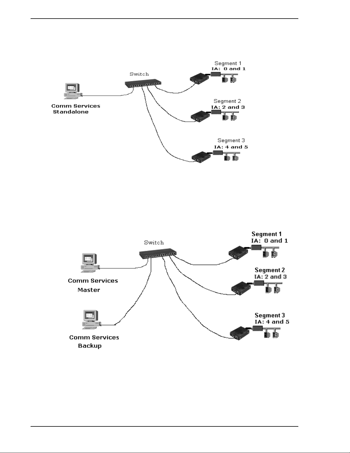
1.8 Micro-DCI Network Architecture
Figure 1-5. Connecting the E-Port Unit to the DataLink Network
A Micro-DCI network is a named network of up to 32 instruments. Each Micro-DCI network in the plant
must have a unique name.
Each network is controlled by a Master Comm Services Node and an optional Backup Comm Services
Node. Each Micro-DCI network has a Network Type. The supported types are:
• Supervisor Card Networks: The network interface is a DataLink or MicroLink Supervisor card.
• COM Port networks: The network interface is a PC COM port.
• Local Networks: There is no physical network interface; the controllers are simulated inside
the PC.
• E-Port Networks: The network interface is a PC Ethernet connection to an E-Port.
Each E-Port unit is assigned to be part of a Micro-DCI E-Port-type network. Depending on the system
architecture, each Micro-DCI E-Port network can have up to 32 segments. Each segment will typically
have one E-port. (Redundant communication configurations may have two E-ports per segment.) Figure 1-
6 through Figure 1-8 illustrate possible network architectu res.
Introduction 9
Page 14
EP1000A E-Port Instruction Manual
Figure 1-6. Typical System Architecture
10 Introduction
Figure 1-7.
System with Redundant PCs
Page 15
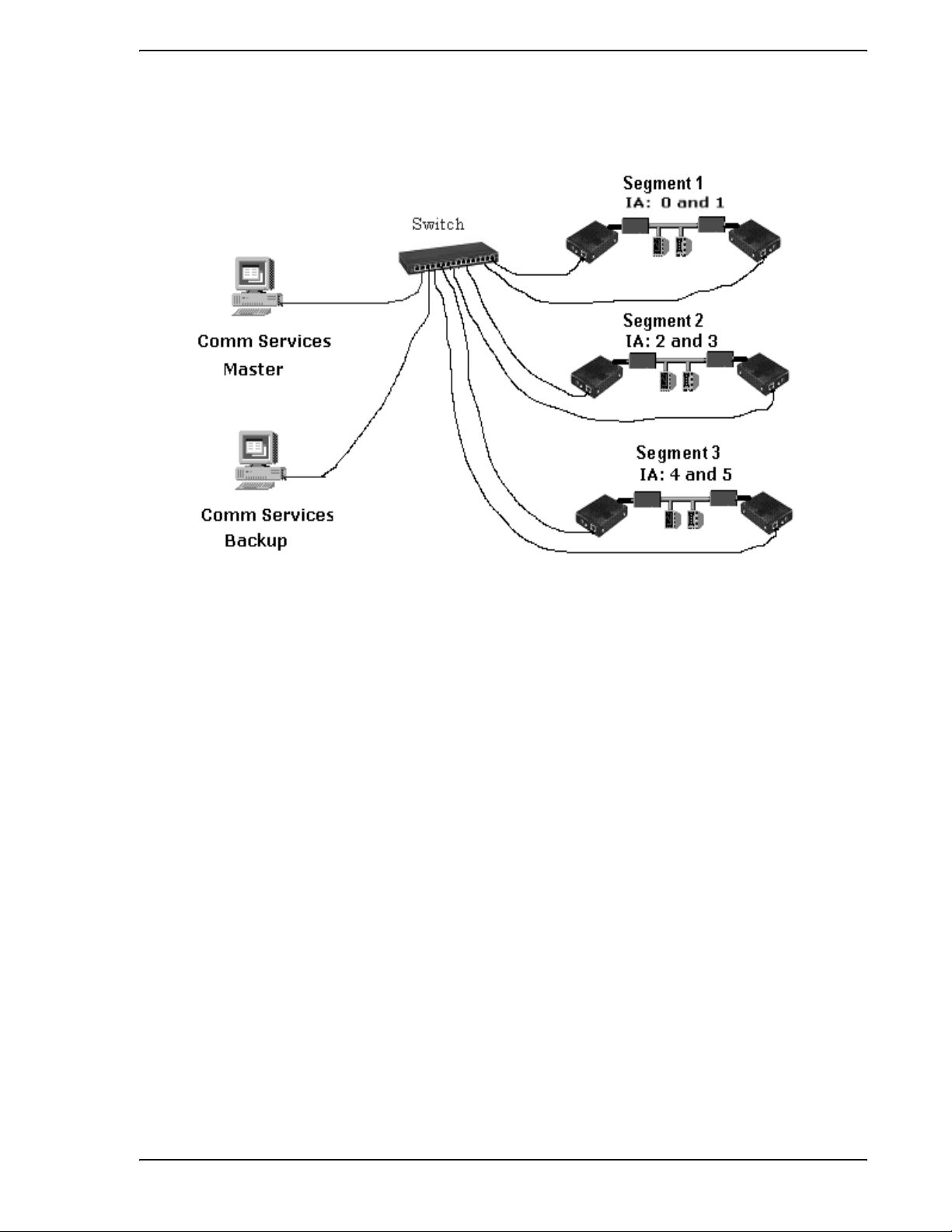
EP1000A E-Port Instruction Manual
Figure 1-8. System with Redundant PCs and Redundant E-Ports
Introduction 11
Page 16
EP1000A E-Port Instruction Manual
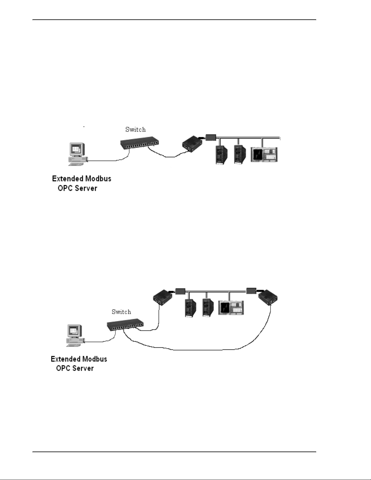
1.9 Modbus Network Architecture
A Modbus network is an RS485 network of up to 32 devices. Redundant communication configurations
may have two E-ports per network. Figure 1-9 through Figure 1-10 illustrate possible network architectures.
Figure 1-9. Typical System Architecture
Figure 1-10. Typic al System Architecture
12 Introduction
Page 17

EP1000A E-Port Instruction Manual
2.0 Installation
2.1 Inspection
An itemized list of all items in the shipment is attached to the shipping container. Inspect the equipment
upon arrival for damage that may have occurred during shipment. All damage claims should be reported to
the responsible shipping agent before installation is attempted. If damage is such that faulty operation is
likely to result, the MicroMo d Auto mation Service Department should be notifi ed.
Inspect the packing material before discarding it as a precaution to prevent loosing mounting hardware or
special instructions that may have been included with the shipment. Normal care in the handling and installation of this equipment will contribute toward its satisfactory performance.
2.2 Location
The E-Port interface unit is designed specifically for indoor mounting. The installation site selected should
be dry and vibration free. The ambient temperature should be stable and maintained within the specified
minimum and maximum temperature limits listed in Section 1.4, Specifications, of this Instruction Manual.
Power requirements are provided in Section 1.4, Specifications.
2.3 Mounting
2.3.1 General
It is normally not necessary to open the E-Port interface unit during installation. If the case of the unit must
be opened, refer to Section 5 for details. Incorrect procedures may damage the unit.
A number of mounting options are available for the E-Port interface unit. These include:
• Wall-mounting (brackets)
• DIN Rail mounting (plastic clips)
• Snap Track mounting (bracket)
Appropriate mounting hardware is supplied by MicroMod Automation Inc., as identified in the product
model number.
Installation 13
Page 18

EP1000A E-Port Instruction Manual
2.3.2 Mounting Procedures
2.3.2.1 Wall Mounting
If wall/DIN rail mounting brackets were specified when the E-Port unit was ordered, the following items are
supplied for mounting the unit:
Part Number Description
122C100U01
To fasten the E-Port unit to a wall or other flat surface, use this procedure. (Note: Set aside the DIN rail
clips, as they will not be used.)
1. Verify that you have both a left and right aluminum bracket. (Place them side by side, with the
flanges pointing away from each other. The tops of the center screw holes in the flanges
should be pointing in the same direction (Figure 2-1).
2. On the E-Port unit, remove the two screws on one side.
3. Align the screw holes in the mounting bracket plate with the screw holes in the side of the EPort unit.
4. Place the screws in the holes and fasten, attaching the mounting bracket to the E-Port unit.
5. Repeat Steps 2 through 4 on the other side of the E-Port unit, using the other mounting
bracket.
6. Use the holes in the flanges to attach the unit directly to the wall, using the screws provided.
2.3.2.2 DIN Rail Mounting
If wall/DIN Rail mounting brackets were specified when the E-Port unit was ordered, the following items
are supplied for mounting the unit:
Mounting hardware package, bagged. This includes:
1 pair (left and right) of aluminum brackets, black
1 pair (identical) of DIN rail clips
4 screws
Part Number Description
122C100U01
To attach the E-Port to a DIN rail, use the following procedure.
14 Installation
Mounting hardware package, bagged. This includes:
1 pair (left and right) of aluminum brackets, black
1 pair (identical) of DIN rail clips
4 screws
Page 19

EP1000A E-Port Instruction Manual
1. Verify that you have both a left and right aluminum bracket. (Place them side by side, with the
flanges pointing away from each other. The tops of the center screw holes in the flanges
should be pointing in the same direction (Figure 2-1).
Figure 2-1. Aluminum Mounting Brackets (Pair)
2. Using two of the screws provided, attach a DIN rail clip to the flange on one of the brackets.
3. Align the second DIN rail clip so that it matches the first clip.
Installation 15
Page 20

EP1000A E-Port Instruction Manual
4. Use the remaining two screws to attach the second clip to the flange of the second bracket.
These assemblies should appear as illustrated in Figure 2-2.
Figure 2-2. DIN Rail Mounting Bracket Assemblies
5. On the E-Port unit, remove the two screws on one side.
6. With the bracket flange facing away from the E-Port unit, align the screw holes in the mounting
bracket with the screw holes in the side of the E-Port unit.
7. Place the screws in the holes and fasten, attaching the mounting bracket to the E-Port unit.
8. Repeat Steps 5 through 7 on the other side of the E-Port unit, using the other mounting
bracket. The final assembly should appear as illustrated in Figure 2-3.
16 Installation
Page 21

EP1000A E-Port Instruction Manual
9. Clip the unit to the DIN rail.
Figure 2-3. E-Port Unit in DIN Rail Mounting
2.3.2.3 Snap Track Mounting
If a Snap Track mounting bracket was specified when the E-Port Unit was ordered, the following items are
supplied for mounting the unit:
Part Number Description
623B600U01
1. Remove the screws from both sides of the E-Port unit.
2. Place the E-Port unit in the mounting bracket (Figure 2-5), taking care to align the holes in the
bracket with the holes in the sides of the unit.
1 aluminum Snap Track bracket
Installation 17
Page 22

EP1000A E-Port Instruction Manual
3. Place the screws through the holes in the brackets and unit sides, and tighten them. The unit
will be fastened in the bracket.
Figure 2-4. E-Port Unit in Snap Track Mounting
4. Snap the bracket into the Snap Track.
Figure 2-5. E-Port Unit with Snap Track Bracket
18 Installation
Page 23

EP1000A E-Port Instruction Manual
2.4 Connections
2.4.1 Power Connections
The E-Port unit is available with these power connection options:
• A standard ac power cable (always sup pli ed with an E-Po rt unit).
• An optional power adapter cable.
• An optional dc power cable.
2.4.1.1 Standard ac Power Connection
Part Number Description Comments / Instructions
699B604U01
AC to DC Power Converter/Cable,
Standard, 100-240 V ac
Provides a power connection
directly from the E-Port unit to an
AC power receptacle.
Figure 2-6. Standard ac to dc Power Converter/Cable, 100-240 V ac
1. Connect the power input plug into the E-Port unit.
2. Connect the standard two-prong transformer plug into the appropriate power source.
Installation 19
Page 24

EP1000A E-Port Instruction Manual
2.4.1.2 Power Adapter Cable Connection (Option al)
Part Number Description Comments / Instructions
677C101U01
Power Adapter Cable, 12-30 V dc Provides the ability to power both
an ITB and the E-Port Unit using
the standard power cable. Can be
connected to either the standard
ac power cable, or the optional dc
power cable.
1. On the RS232/485 ITB, locate TB1.
2. Using the Power Adapter Cable, connect the wire labeled “+” to the terminal labeled +24 on
TB1.
3. Using the Power Adapter Cable, connect the wire labeled “-” to the terminal labeled with the
Ground symbol on TB1.
4. Using the Power Adapter Cable, connect the power input plug to the E-Port unit.
5. Using the Power Adapter Cable, connect the power jack to the power input plug of the
standard ac to dc Power Converter/Cable.
6. Using the standard power cable, connect the two-prong transformer plug into the appropriate
power source.
20 Installation
Figure 2-7. Power Adapter Cable
Page 25

EP1000A E-Port Instruction Manual
2.4.1.3 dc Power Connection (Optional)
Part Number Description Comments / Instructions
677C100U01
The optional dc power cable (Figure 2-8) provides the ability to connect the EP1000A E-Port unit to a dc
power source.
Power Cable, optional, dc Provides the ability to connect to a
dc power source.
Figure 2-8. Optional dc Power Cable
1. Connect the P5-type power plug of the dc power cable into the power jack of the power
adapter cable (Figure 2-7).
2. Connect the + and - wires to the appropriate terminals at your dc power source.
2.4.2 Data Connections
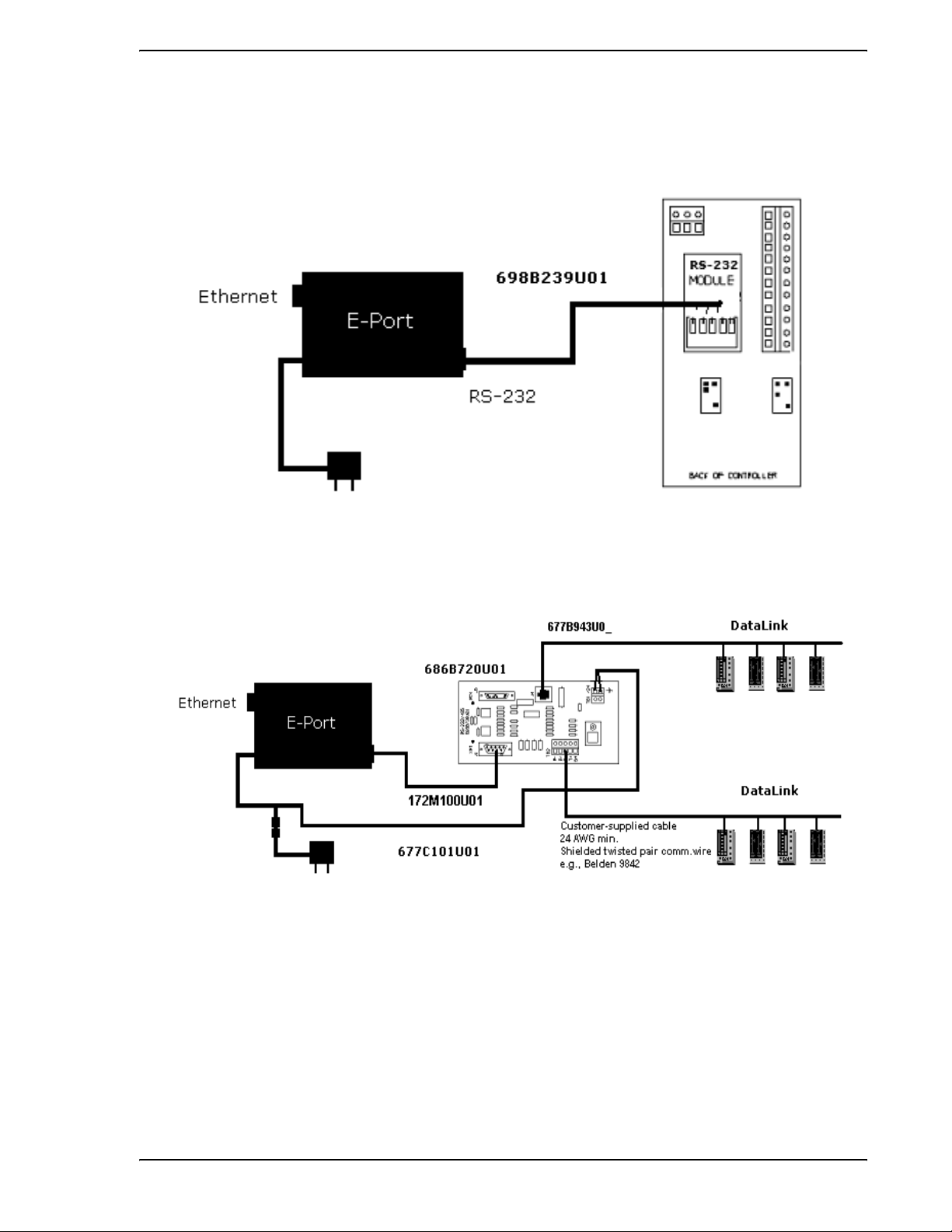
2.4.2.1 Connecting to a 53SL6000 Controller
Part Number Description Comments
698B239U01
Cable, SL6000 front port Provides an RS232 data
connection from the E-Port unit
RS232 port to the data port on a
53SL6000 controller.
Installation 21
Page 26

EP1000A E-Port Instruction Manual
Figure 2-9. E-Port-to-53SL6000 Connection Cable
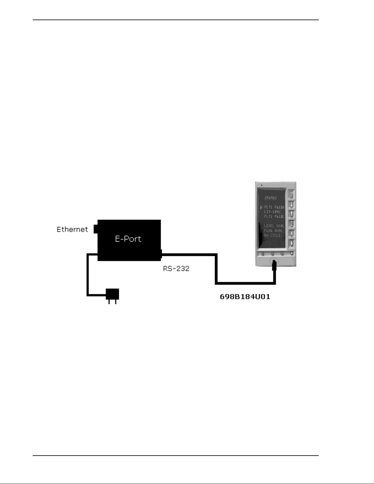
2.4.2.2 Connecting to the Front Port of an MC5000 Unit
Part Number Description Comments
698B184U01
Cable, MC5000 front port Provides a data connection from
the E-Port unit RS232 port to the
front data port on a 53MC5000
controller.
22 Installation
Figure 2-10. E-Port-to-53MC5000 Connection Cable
Page 27

EP1000A E-Port Instruction Manual
2.4.2.3 Connecting to an RS-485 ITB
The E-Port is connected to the RS232 ITB by a standard DB-9 null modem cable.
Part Number Description Comments
172M100U01
172M100U02
Cable, RS232 1’ Null Modem Cable
(9 pin to 9 pin)
Cable, RS232 6’ Null Modem Cable
(9 pin to 9 pin)
Provides a data connection from
the E-Port unit RS232 port to the
RS232 port on a ITB.
Provides a data connection from
the E-Port unit RS232 port to the
RS232 port on a ITB.
Figure 2-11. E-Port-to-ITB Null Modem Cable
Installation 23
Page 28

EP1000A E-Port Instruction Manual
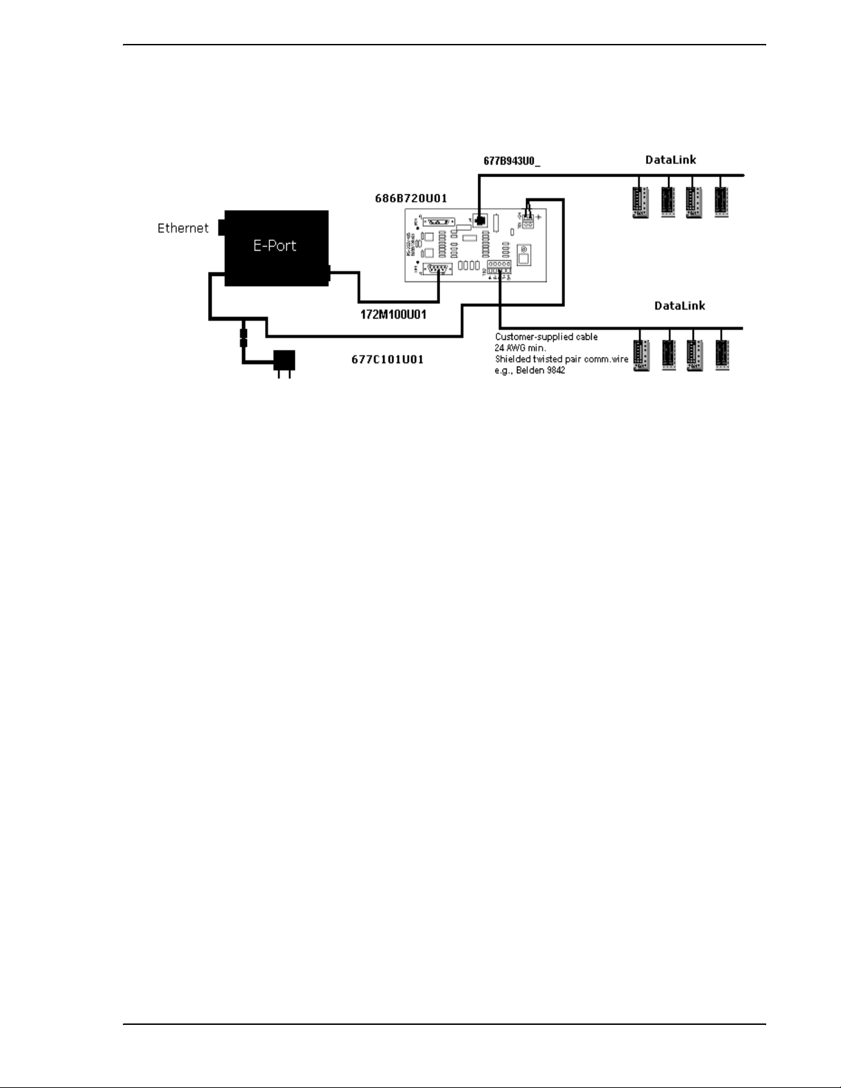
2.4.2.4 Connecting the RS485 ITB to Micro-DCI Controllers
DataLink is an interrogator/responder (sometimes referred to as “master/slave”) serial interface capable of
supporting 32 instruments on a single network. It uses an RS485 physical interface. The DataLink wiring
diagram for this instrument is provided as Figure 2-12.
24 Installation
Figure 2-12. DataLink Installation Diagram
Page 29

EP1000A E-Port Instruction Manual
2.4.2.5 Connecting to a MOD30ML using RS-232
Figure 2-13. MOD30ML RS-232 Installation Diagram
Installation 25
Page 30

EP1000A E-Port Instruction Manual
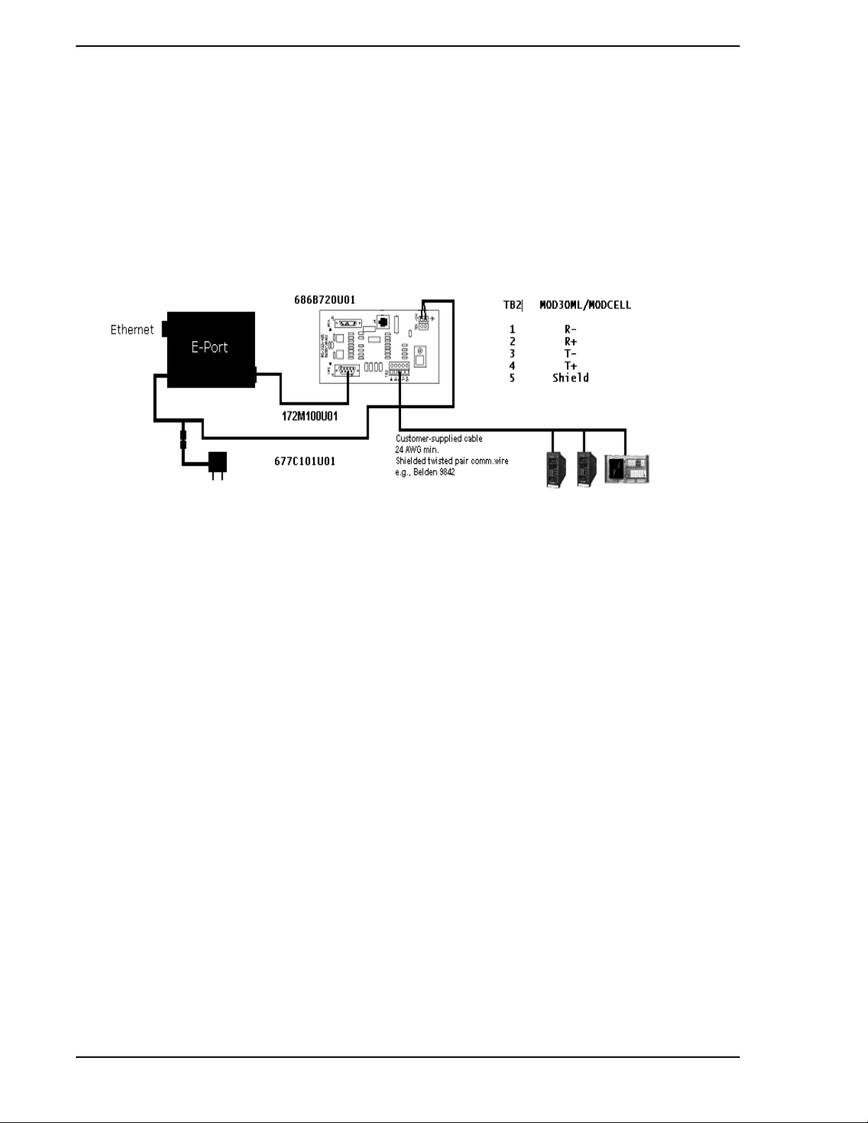
2.4.2.6 Connecting to MOD30MLs using 4 wire RS-485
26 Installation
Figure 2-14. MOD30ML 4 wire RS-485 Installation Diagram
Page 31

EP1000A E-Port Instruction Manual
2.4.2.7 Connecting to a MODCELL using RS-232
Figure 2-15. MODCELL RS-232 Installation Diagram
Installation 27
Page 32

EP1000A E-Port Instruction Manual
2.4.2.8 Connecting to MODCELLs using 4 wire RS-485
28 Installation
Figure 2-16. MODCEL 4 wire RS-485 Installation Diagram
Page 33

EP1000A E-Port Instruction Manual
2.4.3 Ethernet Network Connection
2.4.3.1 Ethernet Network Considera ti ons
Since E-Port networks are high-performance, realtime networks, the following considerations should be
observed when designing your network.
2.4.3.1.1 Installation Requirements
• All E-Ports and their associated PCs must
used between E-Ports and their associated PCs. Switches or routers should be used to isolate
this subnet from the rest of the corporate network, to avoid limiting performance due to heavy
network traffic.
be on the same subnet; that is, no routers can be
• If there are any external firewall devices between the E-Port and the computer, they must
disabled or be configured to pass UDP ports: 20034,4666, and 4669. The Windows XP firewall
is configured automatically by the E-PortSetup application.
• If the E-Port is used to connect your computer with a corporate LAN that uses a proxy server
for Internet web browsing, you must
browser’s proxy server settings/preferences. If this is not done, attempts to connect to a web
page on the LAN will fail, because the proxy server will attempt to route such requests outside
the LAN. For most web browsers, this can be accomplished in the Advanced settings for the
proxy server configuration. Set the network mask to 255.255.255.0.
2.4.3.1.2 Installation Recommendations
For best performance, MicroMod Automation recommends that you:
• Use 100 BaseTx computer interfaces
• Use 100 BaseTx switches, rather than hubs
2.4.3.2 Connecting to an Existing Network
If you are connecting the E-Port unit to an Ethernet switch, use an RJ-45 patch cable to connect the E-Port
unit to an unused network jack.
✎ Notes You cannot use an RJ-45 patch cable to connect the E-Port unit
directly to a network card in a computer.
exclude the IP address of your E-Port unit in your web
be
The RJ-45 cable is not supplied by MicroMod Automation Inc.
2.4.3.3 Connecting Directly to a Network Card in a Computer
If you do not have a switch, and want to connect 1 E-Port unit directly to a computer, use an RJ-45 crossover cable to connect the E-Port unit to the host computer.
✎ Notes You cannot use an RJ-45 patch cable to connect the E-Port unit
directly to a network card in a computer.
The RJ-45 cable is not supplied by MicroMod Automation Inc.
Installation 29
Page 34

EP1000A E-Port Instruction Manual
30 Installation
Page 35

EP1000A E-Port Instruction Manual
3.0 Micro-DCI Software Configuration
3.1 Creating an E-Port Network with Super32
An E-Port Unit is a network interface device used to facilitate data communication between MicroMod
Automation controllers and Communications Services nodes on an E-Port type network. Before you can
use E-Port units, you must have an E-Port network available. E-Port communication is only available on
Version 4.1 (or later) of the Micro-DCI Communication Services software.
To create an E-Port network:
1. From the Windows task bar, select the sequence Start > Programs > MicroMod Auto mation
> Micro-DCI Communications Services > Super32.
2. Right-click on the Communications Services node on which the new network is to be created.
A menu is displayed.
3. Select the Add a new network option on the menu. The Network Wizard window (Figure 3-1)
is displayed.
Figure 3-1. Network Wizard Initial Window
Configuration Parameters 31
Page 36

EP1000A E-Port Instruction Manual
4. On the Network Wiz ard window, click on the E-Port radio button, then click Next. The Network
Attributes window (Figure 3-2) is displayed.
Figure 3-2. Network Attributes Window
5. In the Network Attributes pane, locate the Network Name entry box and enter the name to be
used for the E-Port network. The name can be up to 9 characters in length.
32 Configuration Parameters
Page 37

EP1000A E-Port Instruction Manual
6. Click Next. The Network Mode selection window (Figure 3-3) is displayed.
Figure 3-3. Network Mode Selection Window
7. Choose the mode for the Communications Services node which was selected in Step 2.
Available modes are Standalone, Master, and Backup.
8. Click Next. The Finish window is displayed. The Finish window provides a summary of the
configuration performed for the E-Port network.
9. Click Finish to complete the E-Port network configuration. A confirmation window will advise if
the operation was successful, and an entry for the new network will be displayed, below its
Communications Services node, on the Super32 window.
3.2 Configuring the E-Port
3.2.1 Getting Started
To run the E-Port setup program:
1. Start Super32. To do so from the Windows task bar, select the sequence Start > Programs >
MicroMod > Micro-DCI Communications Services > Super32.
2. From the Super32 Tools menu, select Configure E-Ports to launch the E-Port setup
program.
3.2.2 Configure the E-Port Unit Settings
The E-Port setup program will allow you to view your E-Port unit's current settings, or modify the settings.
Configuration Parameters 33
Page 38

EP1000A E-Port Instruction Manual
3.2.2.1 Configuring the E-Port Unit IP Address
If the network to which the E-Port is connected has a DHCP server running, then the values in the left pane
in the window will be zero, and the IP address assigned by the DHCP server will appear in the Select a
Unit pane as shown below.
Figure 3-4. E-Port Setup Window
If there is no DHCP server running, you must assign a static IP address. See Section 3.2.2.7, How to
Choose an IP Address, below. Enter the information into the NDK Settings pane and click on the Set but-
ton. There will be a short pause while parameters are updated. If you do not see your device in the Select
a Unit pane, click on the Search Again button.
Once the E-Port is listed in the Select a Unit pane, configurati on ca n continu e .
34 Configuration Parameters
Page 39

EP1000A E-Port Instruction Manual
3.2.2.2 Configure E-Port Unit Parameters
Click the Configure E-Port button. This will open up the default web browser, to display the home page for
your E-Port Unit.
Figure 3-5. E-Port Configuration Web Page
Configuration Parameters 35
Page 40

EP1000A E-Port Instruction Manual
3.2.2.3 Assign Device Information to the E-Port Unit
In the E-Port Name entry box, enter a device name of up to 16 characters in length for this E-Port unit.
In the Description entry box, enter a description up to 60 character long for this E-Port unit.
3.2.2.4 Configure Serial Port/Netw ork Set t ing s for the E-Po rt Unit
In the Serial Port Settings portion of the window, locate the Network Name entry box. Enter the name of
the Micro-DCI network, defined in Super32, that this E-Port unit will join.
Locate the Network Protocol drop-down box, and select Micro-DCI DataLink.
To specify the mode of the E-Port Unit, locate the Mode drop-down box and select one of the following
choices:
• Standalone: Choose this option if this will be the only E-Port on this network segment.
• Master: If there will be two E-Port units on this network segment, one of the E-Port units must
be a Master, and the other must be a Backup. Choose this option to designate the Master unit.
• Backup: If there will be two E-Port units on this network segment, one of the E-Port units must
be a Master, and the other must be a Backup. Choose this option to designate the Backup
unit.
To specify the baud rate of the E-Port unit, use the Baud Rate drop-down box and select the baud rate that
matches the baud rate set in the Micro-DCI controllers. See your system administrator if you need information on the baud rate used in the controllers at your site.
To specify the data parity setting for the E-Port unit, use the Parity drop-down box; select the parity setting
that matches the parity set in the Micro-DCI controllers. See your system administrator if you need information on the parity setting in ithe controllers at your site.
To specify the timeout value for the E-Port unit, use the Timeout drop-down box. Normally 10 ms is the
proper value. It may be increased in situation where additional network delay is introduced my a modem.
3.2.2.5 Recording Information onto the E-Port Label
The label on the E-Port unit provides a convenient place to record information about the configuration for
the unit. Spaces are provided, on the label, for the E-Port Name, Network Name, and Description.
3.2.2.6 E-Port Configurat ion Securit y
Y ou can require that a password be entered in order to call up the E-Port Setting web page. To do so, go to
the User Name and Password portion of the E-Port Setup window. Enter a User N a me and a Password in
the appropriate entry boxes. Type the password a second time in the Repeat Password entry box.
✎ Note Be sure to make a note of this user name and password, so you can
call up the E-Port Setting web page again!
3.2.2.7 How to Choose an IP Address
❢ Caution If you are part of an existing network, before proceeding, contact
your network administrator and discuss the requirements listed in
Section 2.4.3.1, Ethernet Network Considerations.
If you are not part of an established network, you can choose any IP address you desire.
36 Configuration Parameters
Page 41

EP1000A E-Port Instruction Manual
You should use one of the following address ranges, that have been reserved for use by isolated networks
if you are creating an isolated network. The first range will be used for all of the examples in the documentation.
10.0.0.0 to 10.255.255.255 Class A
172.16.0.0 to 172.31.255.255 Class B
192.168.0.0 to 192.168.255.255 Class C
For example:
• Set Your PC’s Network Adapter Card IP Address to 10.1.1.10 (only change the Network
Adapter Card, do not change your Dial-Up Adapter settings)
• Set the IP address of the E-Port to 10.1.1.11
• Set the network mask for both the PC network adapter and the E-Port board to 255.255.255.0
3.3 Network Management
3.3.1 Use Super32 to Find an Instrument’s E-Port
Figure 3-6. Initial Super32 Window
1. Browse the tree list to find the instrument for which you want E-Port information.
2. Click on the icon for an instrument to select it.
3. The pane on the right side of the window displays data about the instrument. The Network Port
item shows the E-Port name.
Configuration Parameters 37
Page 42

EP1000A E-Port Instruction Manual
3.3.2 Using Super32 Statistics
Click on the Comm Stats View toolbar button. The network Comm[unications] Stat[istic]s View window will
be displayed for all Micro-DCI networks.
Figure 3-7. Super32 Statistics Display
3.3.3 Using E-Port Diagnostics
To view communications statistics for an E-Port unit, click on the Diagnostics option located at the bottom
of the E-Port Configuration web p age (Figure 3-5). The statistics will be shown in the resulting display
(Figure 3-8). The display lists each of the instruments connected to the E-Port, with each instrument’s type,
number of transactions, and number of errors associated with that instrument.
38 Configuration Parameters
Page 43

EP1000A E-Port Instruction Manual
Figure 3-8. E-Port Statistics Display
The Communication Counters provide the following data:
Total DataLink
Transactions
Total DataLink
Errors
DataLink Status Indicates whether the DataLink is in Active or Standby
The total number of transactions performed on the EPort’s DataLink since the E-Port was powered up.
The total number of errors on the E-Port’s DataLink
since the E-Port was powered up. DataLink errors
indicate a problem in the network wiring or the
instrument’s DataLink.
It is normal for errors to be detected:
• when a master E-Port to Backup E-Port
switchover occurs, or
• when an instrument is disconnected, or
• when an instrument address is changed
mode. An E-Port will be in Standby mode if it is part of
a Master Backup E-Port configuration, and the other
associated E-Port is in Active mode.
Configuration Parameters 39
Page 44

EP1000A E-Port Instruction Manual
40 Configuration Parameters
Page 45

EP1000A E-Port Instruction Manual
4.0 XModbus OPC Server Configuration
4.1 Creating an Ethernet Port
To create an Ethernet Port:
1. From the Windows task bar, select the sequence Start > Programs > MicroMod Auto mation
> XMBOPC > XModbus OPC Server.
2. Click the Edit menu on the menu bar. A menu is displayed.(Figure 4-1
3. Select the Ethernet Ports option on the menu. The Modbus TCP Ports Dialog (Figure 4-2)
will be displayed.
Figure 4-1. Ethernet Ports menu option
Configuration Parameters 41
Page 46

EP1000A E-Port Instruction Manual
4. Click the FInd Ports button and each E-Port on the network will be listed.
Figure 4-2. Modbus TCP Ports Dialog
5. Click OK to close the dialog
4.2 Creating a Device
To create a new XModbus device in the OPC Server
1. Click the New XModbus Device button on the toolbar
42 Configuration Parameters
Figure 4-3. New XModbus Device
Page 47

EP1000A E-Port Instruction Manual
Figure 4-4.
2. Assign a suitable name to the device
3. Sel;ect the E-Port that is wired to the device from the Port dropdown menu
4. Choose a timeout based on the devices response time. This is the time that the OPC server
will wait for a response from the E-Port.
If the OPC Server is the only application accessing the E-Port, a Timeout value of 100ms should
be used.
If there are additional OPC servers also accessing the E-Port the Timout value should be
increased by 50 ms for each additional server.
5. Click the File Name browse button and browse to the .MIF file for the device.
6. Click OK
Configuration Parameters 43
Page 48

EP1000A E-Port Instruction Manual
4.3 Configuring the E-Port
4.3.1 Getting Started
To run the E-Port setup program:
1. Start the XModbus OPC Server and click the Tools menu on the menu bar.
2. Select Configure E-Ports to launch the E-Port setup program.
4.3.2 Configure the E-Port Unit Settings
The E-Port setup program will allow you to view your E-Port unit's current settings, or modify the settings.
4.3.2.1 Configuring the E-Port Unit IP Address
If the network to which the E-Port is connected has a DHCP server running, then the values in the left pane
in the window will be zero, and the IP address assigned by the DHCP server will appear in the Select a
Unit pane as shown below.
Figure 4-5. E-Port Setup Window
If there is no DHCP server running, you must assign a static IP address. See Section 4.3.2.7, How to
Choose an IP Address, below. Enter the information into the NDK Settings pane and click on the Set but-
ton. There will be a short pause while parameters are updated. If you do not see your device in the Select
a Unit pane, click on the Search Again button.
Once the E-Port is listed in the Select a Unit pane, configurati on ca n continu e .
44 Configuration Parameters
Page 49

EP1000A E-Port Instruction Manual
4.3.2.2 Configure E-Port Unit Parameters
Click the Configure E-Port button. This will open up the default web browser, to display the home page for
your E-Port Unit.
Figure 4-6. E-Port Configuration Web Page
Configuration Parameters 45
Page 50

EP1000A E-Port Instruction Manual
4.3.2.3 Assign Device Information to the E-Port Unit
In the E-Port Name entry box, enter a device name of up to 16 characters in length for this E-Port unit.
In the Description entry box, enter a description up to 60 character long for this E-Port unit.
4.3.2.4 Configure Serial Port/Netw ork Set t ing s for the E-Po rt Unit
In the Serial Port Settings portion of the window, locate the Network Name entry box. Enter the name of
the Micro-DCI network, defined in Super32, that this E-Port unit will join.
Locate the Network Protocol drop-down box, and select Modbus
To specify the mode of the E-Port Unit, locate the Mode drop-down box and select one of the following
choices:
• Standalone: Choose this option if this will be the only E-Port on this RS-485 network.
• Master: If there will be two E-Port units on this RS-485 network, one of the E-Port units must
be a Master, and the other must be a Backup. Choose this option to designate the Master unit.
• Backup: If there will be two E-Port units on this network, one of the E-Port units must be a
Master, and the other must be a Backup. Choose this option to designate the Backup unit.
To specify the baud rate of the E-Port unit, use the Baud Rate drop-down box and select the baud rate that
matches the baud rate set in the controllers.
To specify the data parity setting for the E-Port unit, use the Parity drop-down box; select the parity setting
that matches the parity set in the controllers.
To specify the Timeout value, use the Timeout drop-down box. The E-Port will use this value to calculate
how long to wait for a response from the controller. For MOD30ML and Modcell devices, use the 100ms
choice.
4.3.2.5 Recording Information onto the E-Port Label
The label on the E-Port unit provides a convenient place to record information about the configuration for
the unit. Spaces are provided, on the label, for the E-Port Name, Network Name, and Description.
4.3.2.6 E-Port Configurat ion Securit y
Y ou can require that a password be entered in order to call up the E-Port Setting web page. To do so, go to
the User Name and Password portion of the E-Port Setup window. Enter a User N a me and a Password in
the appropriate entry boxes. Type the password a second time in the Repeat Password entry box.
✎ Note Be sure to make a note of this user name and password, so you can
call up the E-Port Setting web page again!
4.3.2.7 How to Choose an IP Address
❢ Caution If you are part of an existing network, before proceeding, contact
your network administrator and discuss the requirements listed in
Section 2.4.3.1, Ethernet Network Considerations.
If you are not part of an established network, you can choose any IP address you desire.
You should use one of the following address ranges, that have been reserved for use by isolated networks
if you are creating an isolated network. The first range will be used for all of the examples in the documentation.
46 Configuration Parameters
Page 51

EP1000A E-Port Instruction Manual
10.0.0.0 to 10.255.255.255 Class A
172.16.0.0 to 172.31.255.255 Class B
192.168.0.0 to 192.168.255.255 Class C
For example:
• Set Your PC’s Network Adapter Card IP Address to 10.1.1.10 (only change the Network
Adapter Card, do not change your Dial-Up Adapter settings)
• Set the IP address of the E-Port to 10.1.1.11
• Set the network mask for both the PC network adapter and the E-Port board to 255.255.255.0
4.4 Network Management
To view communications statistics for an E-Port unit, click on the Diagnostics option located at the bottom
of the E-Port Configuration web p age (Figure 4-6). The statistics will be shown in the resulting display
(Figure 4-7). The display lists each of the instruments connected to the E-Port, with each instrument’s
number of transactions, and number of errors associated with that instrument.
Figure 4-7. E-Port Modbus Statistics Display
Configuration Parameters 47
Page 52

EP1000A E-Port Instruction Manual
The Communication Counters provide the following data:
T otal Transactions The total number of transactions performed on the E-
Port’s Modbus since the E-Port was powered up.
Total Errors The total number of errors on the E-Port’s Modbus
since the E-Port was powered up. Errors indicate a
problem in the network wiring or the instrument’s
Modbus hardware.
It is normal for errors to be detected:
• when a master E-Port to Backup E-Port
switchover occurs, or
• when an instrument is disconnected, or
• when an instrument address is changed
Modbus Status Indicates whether the E-Port is in Active or Standby
mode. An E-Port will be in Standby mode if it is part of
a Master Backup E-Port configuration, and the other
associated E-Port is in Active mode.
48 Configuration Parameters
Page 53

EP1000A E-Port Instruction Manual
5.0 Maintena nc e
5.1 Parts List
The parts list is provided in Table 5-1.
Part Number Description
Table 5-1. Parts List
699B604U01
694A200U01
122C100U01
623B600U01
698B239U01
698B184U01
677C100U01
677C101U01
172M100U01
172M100U02
803F001U01
686B720U01
677B943U0_
EP1000A E-Port, with standard ac power cable
EP1000A E-Port Instruction Manual (hardcopy)
DIN rail mounting bracket kit for EP1000A E-Port
Snap Track mouonting bracket kit for EP1000A E-Port
53SL6000 RS-232 cable
53MC5000 front port cable
Power cable for dc power
Power adapter cable
RS-232 Null modem cable, 1’ length
RS-232 Null modem cable, 6’ length
ITB in DIN rail mounting bracket
ITB for Snap Track mounting
DataLink Cord Set
If a situation arises requiring technical assistance, contact the nearest MicroMod Automation field office.
✎ Note When communicating with MicroMod Automation for replacement
parts, refer to the serial number of the unit to ensure the correct
replacement assembly is supplied. The necessary ordering
information is provided on the instrument data tag and on the
manufacturing specification sheet supplied with that particular
controller.
Maintenance 49
Page 54

EP1000A E-Port Instruction Manual
50 Maintenance
Page 55

Page 56

The Company’s policy is one of continuous product improvement and the
right is reserved to modify the information contained herein without notice, or
to make engineering refinements that may not be reflected in this bulletin.
Micromod Automation assumes no responsibility for errors that may appear
in this manual.
© 2006 MicroMod Automation, Inc. Printed in USA
MicroMod Automation, Inc.
75 Town Centre Drive
Rochester, NY USA 14623
Tel. 585-321-9200
Fax 585-321-9291
www.micromodautomation.com
 Loading...