

Page 1
INSTRUCTION MANUAL
Single Loop Controller
53SL6000
53SL6000 CONTROLLER
PN24991A
Rev. 1
Page 2
MicroMod Automation, Inc.
p
The Company
MicroMod Automation is dedicated to improving customer efficiency by providing the most ost-effective, application-specific process solutions
available. We are a highly responsive, application-focused company with years of expertise in control systems design and implementation.
We are committed to teamwork, high quality manufacturing, advanced technology and unrivaled service and support.
The quality, accuracy and performance of the Company's products result from over 100 years experience, combined with a continuous
program of innovative design and development to incorporate the latest technology.
Use of Instructions
Ì Warning. An instruction that draws attention to the risk of
injury or death.
✎ Note. Clarification of an instruction or additional
information.
❢ Caution. An instruction that draws attention to the risk of
roduct, process or surroundings.
the
Although Warning hazards are related to personal injury, and Caution hazards are associated with equipment or property damage, it
must be understood that operation of damaged equipment could, under certain operational conditions, result in degraded process
system performance leading to personal injury or death. Therefore, comply fully with all Warning and Caution notices.
Information in this manual is intended only to assist our customers in the efficient operation of our equipment. Use of this manual for
any other purpose is specifically prohibited and its contents are not to be reproduced in full or part without prior approval of MicroMod
Automation, Inc.
Licensing, Trademarks and Copyrights
MOD 30 and MOD 30ML are trademarks of MicroMod Automation, Inc.
MODBUS is a trademark of Modicon Inc.
Health and Safety
To ensure that our products are safe and without risk to health, the following points must be noted:
The relevant sections of these instructions must be read carefully before proceeding.
1. Warning Labels on containers and packages must be observed.
2. Installation, operation, maintenance and servicing must only be carried out by suitably trained personnel and in accordance with the
information given or injury or death could result.
3. Normal safety procedures must be taken to avoid the possibility of an accident occurring when operating in conditions of high
4. pressure and/or temperature.
5. Chemicals must be stored away from heat, protected from temperature extremes and powders kept dry. Normal safe handling
procedures must be used.
6. When disposing of chemicals, ensure that no two chemicals are mixed.
Safety advice concerning the use of the equipment described in this manual may be obtained from the Company address on the back
cover, together with servicing and spares information.
i Information. Further reference for more detailed
information or technical details.
All software, including design, appearance, algorithms and source
codes, is copyrighted by MicroMod Automation, inc. and is owned
by MicroMod Automation or its suppliers.
Page 3

Table of Contents 53SL6000 Instruction Manual
Table of Contents
Safety Summary I
Read First II
1.0 Introduction 1-1
1.1 53SL6000 Controller Overview . . . . . . . . . . . . . . . . . . . . . . . . . 1-1
1.2 Controller Model Numbers . . . . . . . . . . . . . . . . . . . . . . . . . . . 1-3
1.3 Product Specifications . . . . . . . . . . . . . . . . . . . . . . . . . . . . . 1-3
2.0 Installation and Power-Up Procedures 2-1
2.1 Inspection . . . . . . . . . . . . . . . . . . . . . . . . . . . . . . . . . 2-1
2.2 Site Location . . . . . . . . . . . . . . . . . . . . . . . . . . . . . . . . . 2-1
2.3 Panel Mounting . . . . . . . . . . . . . . . . . . . . . . . . . . . . . . . . 2-1
2.3.1 Single Cutout Installation (NEMA4 Compliant) . . . . . . . . . . . . . . . 2-1
2.3.2 Multiple Cutout Installation . . . . . . . . . . . . . . . . . . . . . . . 2-1
2.4 Power Connections . . . . . . . . . . . . . . . . . . . . . . . . . . . . . . 2-1
2.4.1 24 V DC Power Connections . . . . . . . . . . . . . . . . . . . . . . 2-3
2.4.2 AC Power Connections . . . . . . . . . . . . . . . . . . . . . . . . . 2-3
2.5 Signal Connections . . . . . . . . . . . . . . . . . . . . . . . . . . . . . . 2-3
2.5.1 Analog Inputs AI1 and AI2 . . . . . . . . . . . . . . . . . . . . . . . 2-4
2.5.2 Discrete Outputs DO1 and DO2 . . . . . . . . . . . . . . . . . . . . . 2-4
2.5.3 Discrete Inputs DI1 and DI2 . . . . . . . . . . . . . . . . . . . . . . . 2-4
2.5.4 Analog Output AO1 . . . . . . . . . . . . . . . . . . . . . . . . . . 2-4
2.6 Universal Analog Input Module . . . . . . . . . . . . . . . . . . . . . . . . . 2-5
2.6.1 Universal Analog Input Module Backplane Installation . . . . . . . . . . . . 2-5
2.6.2 Universal Analog Input Module Signal Wiring . . . . . . . . . . . . . . . 2-5
2.6.2.1 Thermocouple Connections and Burn-out Detection . . . . . . . . . 2-5
2.7 2DI/2DO Module . . . . . . . . . . . . . . . . . . . . . . . . . . . . . . . 2-6
2.7.1 2DI/2DO Backplane Installation . . . . . . . . . . . . . . . . . . . . . 2-6
2.7.2 2DI/2DO Signal Wiring . . . . . . . . . . . . . . . . . . . . . . . . . 2-6
2.8 RS-232 and RS-485 Modules . . . . . . . . . . . . . . . . . . . . . . . . . . 2-7
2.8.1 RS-232 Plug Connections . . . . . . . . . . . . . . . . . . . . . . . 2-7
2.8.2 RS-485 Plug Connections . . . . . . . . . . . . . . . . . . . . . . . 2-7
2.9 Applying Power . . . . . . . . . . . . . . . . . . . . . . . . . . . . . . . . 2-7
2.9.1 Power-up Sequence . . . . . . . . . . . . . . . . . . . . . . . . . . 2-8
3.0 Display Panel 3-1
3.1 Display Panel Overview . . . . . . . . . . . . . . . . . . . . . . . . . . . . 3-1
3.2 Operator Mode . . . . . . . . . . . . . . . . . . . . . . . . . . . . . . . . 3-1
3.2.1 Operator Mode Panel Functions . . . . . . . . . . . . . . . . . . . . . . . . 3-1
3.3 Auxiliary Operator Access . . . . . . . . . . . . . . . . . . . . . . . . . . . 3-4
3.4 Operator Mode Overflow/ Underflow Indication . . . . . . . . . . . . . . . 3-4
i
Page 4

53SL6000 Instruction Manual Table of Contents
3.5 Engineer Mode . . . . . . . . . . . . . . . . . . . . . . . . . . . . . . . 3-5
3.5.1 Engineer Mode Display Panel . . . . . . . . . . . . . . . . . . . . . 3-5
3.5.2 Engineer Mode Hierarchical Structure . . . . . . . . . . . . . . . . . . 3-5
3.5.2.1 Editing a Parameter . . . . . . . . . . . . . . . . . . . . . 3-5
3.5.2.2 Deselecting and Scrolling Backward . . . . . . . . . . . . . . 3-6
3.5.2.3 Editing a Numeric Value . . . . . . . . . . . . . . . . . . . 3-6
3.5.2.4 Editing the Tag Parameter . . . . . . . . . . . . . . . . . . 3-7
3.6 Entering a Pass-Key . . . . . . . . . . . . . . . . . . . . . . . . . . . . . 3-8
3.6.1 Configuring a Pass-Key . . . . . . . . . . . . . . . . . . . . . . . . 3-8
3.7 Offline Display Pattern . . . . . . . . . . . . . . . . . . . . . . . . . . . . 3-8
3.8 Engineer Mode oPEr Selections . . . . . . . . . . . . . . . . . . . . . . . . 3-9
3.9 Display Alphanumerics . . . . . . . . . . . . . . . . . . . . . . . . . . . . 3-11
3.10 Engineer Mode Summary . . . . . . . . . . . . . . . . . . . . . . . . . . 3-11
4.0 Functional Overview 4-1
4.1 Simplified Block Diagram . . . . . . . . . . . . . . . . . . . . . . . . . . . 4-1
4.2 Detailed Block Diagram . . . . . . . . . . . . . . . . . . . . . . . . . . . . 4-2
5.0 Inputs/Outputs (I/O) 5-1
5.1 I/O Overview . . . . . . . . . . . . . . . . . . . . . . . . . . . . . . . . 5-1
5.2 Analog Inputs . . . . . . . . . . . . . . . . . . . . . . . . . . . . . . . . 5-1
5.3 Universal Analog Input Module . . . . . . . . . . . . . . . . . . . . . . . . . 5-2
5.3.1 Universal Analog Input Module Parameter Entries . . . . . . . . . . . . . 5-2
5.4 Analog Output 1 (AO1) . . . . . . . . . . . . . . . . . . . . . . . . . . . . 5-4
5.5 Discrete Inputs . . . . . . . . . . . . . . . . . . . . . . . . . . . . . . . 5-5
5.6 Discrete Outputs . . . . . . . . . . . . . . . . . . . . . . . . . . . . . . . 5-5
5.7 RS-232 and RS-485 Options . . . . . . . . . . . . . . . . . . . . . . . . . . 5-6
6.0 Signal Value Modification 6-1
6.1 Section Overview . . . . . . . . . . . . . . . . . . . . . . . . . . . . . . 6-1
6.2 Characterizer . . . . . . . . . . . . . . . . . . . . . . . . . . . . . . . . 6-1
6.2.1. 3SEG Mode . . . . . . . . . . . . . . . . . . . . . . . . . . . . 6-2
6.2.2 LSEG Mode . . . . . . . . . . . . . . . . . . . . . . . . . . . . . 6-2
6.2.3 PrGM Mode . . . . . . . . . . . . . . . . . . . . . . . . . . . . . 6-3
6.2.4 DtoA Mode . . . . . . . . . . . . . . . . . . . . . . . . . . . . . 6-4
6.3 Math Function Block . . . . . . . . . . . . . . . . . . . . . . . . . . . . . 6-4
6.3.1 ALG Mode . . . . . . . . . . . . . . . . . . . . . . . . . . . . . 6-5
6.3.2 SuMM Mode . . . . . . . . . . . . . . . . . . . . . . . . . . . . 6-5
6.3.3 PoLY Mode . . . . . . . . . . . . . . . . . . . . . . . . . . . . . 6-6
6.3.4 PoWr Mode . . . . . . . . . . . . . . . . . . . . . . . . . . . . . 6-6
6.3.5 LoG Mode . . . . . . . . . . . . . . . . . . . . . . . . . . . . . 6-6
6.3.6 LiM Mode . . . . . . . . . . . . . . . . . . . . . . . . . . . . . 6-6
6.3.7 SEL Mode . . . . . . . . . . . . . . . . . . . . . . . . . . . . . 6-7
6.3.8 Gas Flow Compensation Equations . . . . . . . . . . . . . . . . . . . 6-7
6.3.8.1 Linear Gas Flow Compensation (LFLo) Equation . . . . . . . . . 6-7
6.3.8.2 Square Root Gas Flow Compensation (SFLo) Equation . . . . . . 6-7
6.4 Logic Blocks 1, 2, 3, and 4 . . . . . . . . . . . . . . . . . . . . . . . . . . 6-7
ii
Page 5

Table of Contents 53SL6000 Instruction Manual
7.0 Control Scheme Block 7-1
7.1 Control Scheme Block . . . . . . . . . . . . . . . . . . . . . . . . . . . . . 7-1
7.2 Control Scheme Inputs . . . . . . . . . . . . . . . . . . . . . . . . . . . . . 7-1
7.3 Control Scheme Control Signals . . . . . . . . . . . . . . . . . . . . . . . . . 7-1
7.4 Signal Paths for the SnGL, cASc, L.LiM, and h.LiM Control Schemes . . . . . . . . . 7-6
7.4.1 Setpoint (SP-PV) Paths for the SnGL, cASc, L.LiM, and h.LiM Control . . . . . 7-6
7.4.2 PID Paths for the SnGL, cASc, L.LiM, and h.LiM Control Schemes . . . . . . 7-6
7.4.3 OUT Paths for the SnGL, cASc, L.LiM, and h.LiM Control Schemes . . . . . . 7-6
7.5 Signal Paths for the in.Ld Control Scheme . . . . . . . . . . . . . . . . . . . . . 7-7
7.6 Control Scheme Parameters . . . . . . . . . . . . . . . . . . . . . . . . . 7-24
7.7 Control Loop Parameters . . . . . . . . . . . . . . . . . . . . . . . . . . . 7-25
7.8 Control Scheme Signal Connector Pin Assignments . . . . . . . . . . . . . . . . 7-28
8.0 Eight Control Strategies 8-1
8.1 Single Loop Control with Remote Setpoint . . . . . . . . . . . . . . . . . . . . 8-1
8.1.1 AI1 - Process Variable Input . . . . . . . . . . . . . . . . . . . . . . 8-2
8.1.2 AI2 - Remote Setpoint Input . . . . . . . . . . . . . . . . . . . . . . . 8-2
8.1.3 DO1 - PV High Alarm Contact Out . . . . . . . . . . . . . . . . . . . . 8-2
8.1.4 DO2 - PV Low Alarm Contact Out . . . . . . . . . . . . . . . . . . . . 8-2
8.1.5 DI1 - Force Control Output Contact Input . . . . . . . . . . . . . . . . . 8-2
8.1.6 DI2 - Remote Enable Contact Input . . . . . . . . . . . . . . . . . . . 8-2
8.1.7 AO1 - Control Output . . . . . . . . . . . . . . . . . . . . . . . . . 8-2
8.1.8 SchM Selection . . . . . . . . . . . . . . . . . . . . . . . . . . . . 8-2
8.2 Analog Back-Up Control . . . . . . . . . . . . . . . . . . . . . . . . . . . . 8-3
8.2.1 AI1 - Process Variable Input . . . . . . . . . . . . . . . . . . . . . . 8-4
8.2.2 AI2 - Control Element Feedback . . . . . . . . . . . . . . . . . . . . . 8-4
8.2.3 DO1 - Computer Output Diverter . . . . . . . . . . . . . . . . . . . . . 8-4
8.2.4 DO2 - Backup Output Diverter . . . . . . . . . . . . . . . . . . . . . . 8-4
8.2.5 DI1 - Computer Ready . . . . . . . . . . . . . . . . . . . . . . . . . 8-4
8.2.6 DI2 - Auto Enable . . . . . . . . . . . . . . . . . . . . . . . . . . . 8-4
8.2.7 A01 - Backup Control Output . . . . . . . . . . . . . . . . . . . . . . 8-4
8.2.8 SchM Selection and Path Connections . . . . . . . . . . . . . . . . . . 8-4
8.3 Ratio Control . . . . . . . . . . . . . . . . . . . . . . . . . . . . . . . . . 8-5
8.3.1 AI1 - Controlled Variable Input . . . . . . . . . . . . . . . . . . . . . 8-5
8.3.2 AI2 - Wild Variable Input . . . . . . . . . . . . . . . . . . . . . . . . 8-5
8.3.3 DO1 - Controlled Variable High Alarm Contact Out . . . . . . . . . . . . . 8-5
8.3.4 DO2 - Controlled Variable Low Alarm Contact Out . . . . . . . . . . . . . 8-5
8.3.5 DI1 - Force Control Output Contact Input . . . . . . . . . . . . . . . . . 8-6
8.3.6 DI2 - Ratio Enable Contact Input . . . . . . . . . . . . . . . . . . . . . 8-6
8.3.7 Control Output . . . . . . . . . . . . . . . . . . . . . . . . . . . . 8-6
8.3.8 SPM = K-SP . . . . . . . . . . . . . . . . . . . . . . . . . . . . . 8-6
8.3.9 SchM Selection . . . . . . . . . . . . . . . . . . . . . . . . . . . . 8-6
8.4 Auto/Manual Selector . . . . . . . . . . . . . . . . . . . . . . . . . . . . . 8-7
8.4.1 AI1 - Process Variable 1 Input . . . . . . . . . . . . . . . . . . . . . . 8-7
8.4.2 AI2 - Process Variable 2 Input (Auto) . . . . . . . . . . . . . . . . . . . 8-7
8.4.3 DO1 - PV1 High Alarm Contact Out . . . . . . . . . . . . . . . . . . . 8-7
8.4.4 D02 - PV1 Low Alarm Contact Out . . . . . . . . . . . . . . . . . . . . 8-8
8.4.5 DI1 Force Output Contact Input . . . . . . . . . . . . . . . . . . . . . 8-8
8.4.7 A01 - PV2 Re-Transmit (Auto) . . . . . . . . . . . . . . . . . . . . . . 8-8
8.4.8 SchM Selection . . . . . . . . . . . . . . . . . . . . . . . . . . . . 8-8
iii
Page 6

53SL6000 Instruction Manual Table of Contents
8.5 Single Station Cascade Control . . . . . . . . . . . . . . . . . . . . . . . . 8-9
8.5.1 AI1 - Secondary PV Input . . . . . . . . . . . . . . . . . . . . . . . 8-9
8.5.2 AI2 - Primary PV Input . . . . . . . . . . . . . . . . . . . . . . . . 8-9
8.5.3 DO1 - Secondary PV High Alarm Contact Out . . . . . . . . . . . . . . 8-9
8.5.4 DO2 - Secondary PV Low Alarm Contact Out . . . . . . . . . . . . . . 8-10
8.5.5 DI1 - Force Control Output Contact Input . . . . . . . . . . . . . . . . 8-10
8.5.6 DI2 - Cascade Enable Contact Input . . . . . . . . . . . . . . . . . . 8-10
8.5.7 Primary Output (the Setpoint into the Secondary Loop) . . . . . . . . . . . 8-10
8.5.8 AO1 - Control Output . . . . . . . . . . . . . . . . . . . . . . . . . 8-10
8.5.9 SchM Selection . . . . . . . . . . . . . . . . . . . . . . . . . . . 8-10
8.6 Single Station Override Control . . . . . . . . . . . . . . . . . . . . . . . . 8-11
8.6.1 AI1 - Primary PV Input . . . . . . . . . . . . . . . . . . . . . . . . 8-11
8.6.2 AI2 - Limiting PV Input . . . . . . . . . . . . . . . . . . . . . . . . 8-11
8.6.3 DO1 - Primary PV High AlarmContact Out . . . . . . . . . . . . . . . . 8-11
8.6.4 DO2 - Primary PV Low Alarm Contact Out . . . . . . . . . . . . . . . . 8-12
8.6.5 DI1 - Force Control Output Contact Input . . . . . . . . . . . . . . . . 8-12
8.6.6 DI2 - Secondary Setpoint Enable . . . . . . . . . . . . . . . . . . . . 8-12
8.6.7 AO1 - Control Output . . . . . . . . . . . . . . . . . . . . . . . . . 8-12
8.6.8 SchM Selection . . . . . . . . . . . . . . . . . . . . . . . . . . . 8-12
8.7 Dual Indicator with Re-Transmitted PV . . . . . . . . . . . . . . . . . . . . . 8-13
8.7.1 AI1 - PV1 Input . . . . . . . . . . . . . . . . . . . . . . . . . . . 8-13
8.7.2 AI2 - PV2 Input . . . . . . . . . . . . . . . . . . . . . . . . . . . 8-13
8.7.3 DO1 - PV1 High Alarm Contact Out . . . . . . . . . . . . . . . . . . . 8-13
8.7.4 DO2 - PV1 Low Alarm Contact Out . . . . . . . . . . . . . . . . . . . 8-13
8.7.5 A01 - Retransmitted PV1 or PV2 . . . . . . . . . . . . . . . . . . . . 8-13
8.7.6 SchM Selection . . . . . . . . . . . . . . . . . . . . . . . . . . . 8-13
8.8 Proportional Speed Floating Control . . . . . . . . . . . . . . . . . . . . . . 8-14
8.8.1 Motorized Valve Connections . . . . . . . . . . . . . . . . . . . . . 8-14
8.8.2 Configuration Requirements . . . . . . . . . . . . . . . . . . . . . . 8-14
8.8.3 Speed Factor Adjusting . . . . . . . . . . . . . . . . . . . . . . . . 8-15
9.0 Commissioning 9-1
9.1 Overview . . . . . . . . . . . . . . . . . . . . . . . . . . . . . . . . . . 9-1
9.2 Proportional Action (Pb) . . . . . . . . . . . . . . . . . . . . . . . . . . . . 9-1
9.3 Integral Action (tr) . . . . . . . . . . . . . . . . . . . . . . . . . . . . . . 9-1
9.4 Derivative Action (td) . . . . . . . . . . . . . . . . . . . . . . . . . . . . . 9-2
9.5 Trial and Error Tuning Method . . . . . . . . . . . . . . . . . . . . . . . . . 9-2
9.6 Proportional Cycle Tuning Method . . . . . . . . . . . . . . . . . . . . . . . 9-2
9.7 Step Response Tuning Method (Ziegler-Nichols) . . . . . . . . . . . . . . . . . 9-2
9.8 Easy-Tune . . . . . . . . . . . . . . . . . . . . . . . . . . . . . . . . 9-3
9.8.1 Executing Easy-Tune . . . . . . . . . . . . . . . . . . . . . . . . . 9-5
9.8.2 Easy-Tune Determined Values . . . . . . . . . . . . . . . . . . . . . 9-7
9.8.3 Easy-Tune Status Responses . . . . . . . . . . . . . . . . . . . . . 9-7
9.8.3.1 out Response . . . . . . . . . . . . . . . . . . . . . . . . 9-8
9.8.3.2 dout Response . . . . . . . . . . . . . . . . . . . . . . . 9-8
9.8.3.3 dPV Response . . . . . . . . . . . . . . . . . . . . . . . 9-8
9.8.3.4 outX Response . . . . . . . . . . . . . . . . . . . . . . . 9-8
9.8.3.5 StiM Response . . . . . . . . . . . . . . . . . . . . . . . 9-8
9.8.3.6 PtiM Response . . . . . . . . . . . . . . . . . . . . . . . 9-8
9.8.3.7 WtiM Response . . . . . . . . . . . . . . . . . . . . . . . 9-8
9.8.3.8 KtiM Response . . . . . . . . . . . . . . . . . . . . . . . 9-8
9.8.3.9 ttiM Response . . . . . . . . . . . . . . . . . . . . . . . 9-8
9.8.3.10 Abrt Response . . . . . . . . . . . . . . . . . . . . . . . 9-8
iv
Page 7

Table of Contents 53SL6000 Instruction Manual
9.8.3.11 PidL Response . . . . . . . . . . . . . . . . . . . . . . . 9-8
9.8.3.12 cM Response . . . . . . . . . . . . . . . . . . . . . . . . 9-8
9.8.3.13 cASc Response . . . . . . . . . . . . . . . . . . . . . . . 9-8
9.8.3.14 oVr Response . . . . . . . . . . . . . . . . . . . . . . . . 9-8
Appendix A: Glossary A-1
Appendix B: Maintenance and Parts List B-1
B.1 Overview . . . . . . . . . . . . . . . . . . . . . . . . . . . . . . . . . . B-1
B.2 Parts List . . . . . . . . . . . . . . . . . . . . . . . . . . . . . . . . . . B-1
B.3 Removal and Replacement . . . . . . . . . . . . . . . . . . . . . . . . . . . B-2
B.4 Controller Confidence Test Procedure . . . . . . . . . . . . . . . . . . . . . . B-3
B.4.1 Jumper Connections for the Controller Confidence Test . . . . . . . . . . . B-3
B.4.2 Starting the Controller Confidence Test via the Faceplate Push Buttons . . . . B-4
B.4.3 Starting the Controller Confidence Test via Datalink . . . . . . . . . . . . B-4
B.4.4 Controller Confidence Test Suite . . . . . . . . . . . . . . . . . . . . B-5
B.4.5 Controller Confidence Test Status . . . . . . . . . . . . . . . . . . . . B-5
B.4.6 Exiting the Controller Confidence Test via the Faceplate Push Buttons . . . . . B-5
B.4.7 Exiting the Controller Confidence Test via Datalink . . . . . . . . . . . . . B-5
B.5 Defaulting the Database . . . . . . . . . . . . . . . . . . . . . . . . . . . . B-6
B.6 Analog Input/Output Calibration Values . . . . . . . . . . . . . . . . . . . . . . B-6
B.7 Watchdog LED . . . . . . . . . . . . . . . . . . . . . . . . . . . . . . . . B-6
Appendix C: Datalink Protocol C-1
C.1 Overview . . . . . . . . . . . . . . . . . . . . . . . . . . . . . . . . . . C-1
C.2 Configuring the System Module for Datalink . . . . . . . . . . . . . . . . . . . . C-1
C.3 Protocol . . . . . . . . . . . . . . . . . . . . . . . . . . . . . . . . . . . C-1
C.3.1 Message Types . . . . . . . . . . . . . . . . . . . . . . . . . . . . C-2
C.3.2 Transaction Examples . . . . . . . . . . . . . . . . . . . . . . . . . C-2
C.4 Mnemonic-to-Datapoint Cross Reference . . . . . . . . . . . . . . . . . . . . . C-3
C.4.1 Database Starting Addresses . . . . . . . . . . . . . . . . . . . . . . C-3
C.4.2 Controller Memory Address Scheme . . . . . . . . . . . . . . . . . . . C-3
C.4.3 Database Prompt-to-Datapoint Cross Reference . . . . . . . . . . . . . . C-5
C.5 Executing Controller Self Tests via Datalink . . . . . . . . . . . . . . . . . . . . C-8
Appendix D: Prompt List D-1
Photocopy-Ready Pocket Reference Guide Last Sheet
v
Page 8

53SL6000 Instruction Manual Table of Contents
List of Tables
Table 1-1. 53SL6000 Model Numbers . . . . . . . . . . . . . . . . . . . . . . . . 1-3
Table 2-1. Controller Status Codes . . . . . . . . . . . . . . . . . . . . . . . . . 2-8
Table 3-1. Operator Mode Display Items . . . . . . . . . . . . . . . . . . . . . . 3-3
Table 3-2. Setpoint Up/Down Push Buttons . . . . . . . . . . . . . . . . . . . . . 3-4
Table 3-3. oPEr Menu Selections . . . . . . . . . . . . . . . . . . . . . . . . . 3-9
Table 3-4. Operator Enable (oPr) Prompts . . . . . . . . . . . . . . . . . . . . . 3-11
Table 5-1. Analog Input Selections . . . . . . . . . . . . . . . . . . . . . . . . . 5-1
Table 5-2. Analog Input Registers . . . . . . . . . . . . . . . . . . . . . . . . . 5-1
Table 5-3. Input Type Prompts . . . . . . . . . . . . . . . . . . . . . . . . . . 5-2
Table 5-4. Volt/Millivolt Input Types . . . . . . . . . . . . . . . . . . . . . . . . 5-3
Table 5-5. Thermocouple Types . . . . . . . . . . . . . . . . . . . . . . . . . . 5-3
Table 5-6. RTD Types . . . . . . . . . . . . . . . . . . . . . . . . . . . . . . 5-3
Table 5-7. Frequency/Pulse Input Types . . . . . . . . . . . . . . . . . . . . . . 5-4
Table 5-8. Calibration Constants . . . . . . . . . . . . . . . . . . . . . . . . . . 5-4
Table 5-9. Analog Output Selections . . . . . . . . . . . . . . . . . . . . . . . . 5-4
Table 5-10. Analog Output Registers . . . . . . . . . . . . . . . . . . . . . . . . 5-4
Table 5-11. Discrete Input Selections . . . . . . . . . . . . . . . . . . . . . . . 5-5
Table 5-12. Discrete Output Selections . . . . . . . . . . . . . . . . . . . . . . . 5-5
Table 5-13. System (SYS) Prompts . . . . . . . . . . . . . . . . . . . . . . . . 5-6
Table 6-1. Characterizer Parameters . . . . . . . . . . . . . . . . . . . . . . . . 6-1
Table 6-2. Math Function Block Parameters . . . . . . . . . . . . . . . . . . . . . 6-5
Table 6-3. Logic Block Parameters . . . . . . . . . . . . . . . . . . . . . . . . . 6-8
Table 6-4. Discrete Logic Block Functions . . . . . . . . . . . . . . . . . . . . . . 6-8
Table 7-1. Control Signal Descriptions . . . . . . . . . . . . . . . . . . . . . . . 7-3
Table 7-2. Control Scheme Parameters . . . . . . . . . . . . . . . . . . . . . . . 7-24
Table 7-3. Control Selections . . . . . . . . . . . . . . . . . . . . . . . . . . . 7-25
Table 9-1. ITAE Equations . . . . . . . . . . . . . . . . . . . . . . . . . . . . 9-3
Table 9-2. Easy-Tune Parameters . . . . . . . . . . . . . . . . . . . . . . . . . 9-7
Table 9-3. Easy-Tune Determined Values . . . . . . . . . . . . . . . . . . . . . . 9-7
Table B-1. Parts List . . . . . . . . . . . . . . . . . . . . . . . . . . . . . . . B-2
Table B-2. Confidence Test Suite . . . . . . . . . . . . . . . . . . . . . . . . . B-5
Table B-3. Factory Subtest Descriptions . . . . . . . . . . . . . . . . . . . . . . B-5
Table C-1. System (SYS) Prompts (Datalink) . . . . . . . . . . . . . . . . . . . . C-1
Table C-2. Datalink Protocol . . . . . . . . . . . . . . . . . . . . . . . . . . . C-1
Table C-3. Datapoint Types . . . . . . . . . . . . . . . . . . . . . . . . . . . . C-3
Table C-4. Database Starting Addresses . . . . . . . . . . . . . . . . . . . . . . C-3
Table C-5. Datapoint Addresses . . . . . . . . . . . . . . . . . . . . . . . . . . C-3
Table C-6. Prompt-to-Datapoint Cross Reference . . . . . . . . . . . . . . . . . . . C-5
vi
Page 9

Table of Contents 53SL6000 Instruction Manual
List of Figures
Figure 1-1. 53SL6000 Controller . . . . . . . . . . . . . . . . . . . . . . . . . . . 1-2
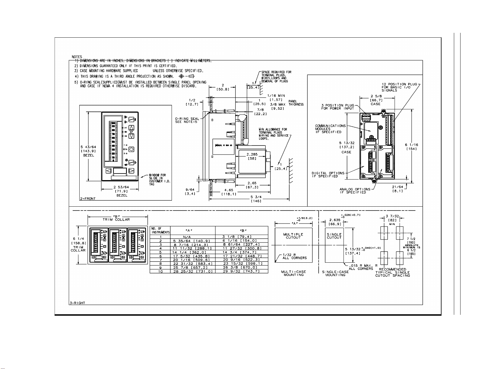
Figure 2-1. Panel Cutout and Installation . . . . . . . . . . . . . . . . . . . . . . . 2-2
Figure 2-2. Power Plug . . . . . . . . . . . . . . . . . . . . . . . . . . . . . . 2-3
Figure 2-3. 24 V DC Power Connections . . . . . . . . . . . . . . . . . . . . . . . 2-3
Figure 2-4. AC Power Connections . . . . . . . . . . . . . . . . . . . . . . . . . 2-3
Figure 2-5. Signal Plug . . . . . . . . . . . . . . . . . . . . . . . . . . . . . . 2-4
Figure 2-6. Signal Plug Connections . . . . . . . . . . . . . . . . . . . . . . . . . 2-4
Figure 2-7. Universal Analog Input Module . . . . . . . . . . . . . . . . . . . . . . 2-5
Figure 2-8. Input Configurations . . . . . . . . . . . . . . . . . . . . . . . . . . . 2-6
Figure 2-9. 2DI/2DO Module . . . . . . . . . . . . . . . . . . . . . . . . . . . . 2-6
Figure 2-10. 2DI Plug Connections . . . . . . . . . . . . . . . . . . . . . . . . . 2-6
Figure 2-11. 2DO Plug Connections . . . . . . . . . . . . . . . . . . . . . . . . . 2-7
Figure 2-12. RS-232 or RS-485 Module . . . . . . . . . . . . . . . . . . . . . . . 2-7
Figure 2-13. RS-232 Plug Connections . . . . . . . . . . . . . . . . . . . . . . . . 2-7
Figure 2-14. RS-485 Plug Connections . . . . . . . . . . . . . . . . . . . . . . . . 2-7
Figure 3-1. Display Panel Overview . . . . . . . . . . . . . . . . . . . . . . . . . 3-1
Figure 3-3. Overflow/Underflow Indicators . . . . . . . . . . . . . . . . . . . . . . 3-4
Figure 3-4. Engineer Mode Display Panel . . . . . . . . . . . . . . . . . . . . . . . 3-5
Figure 3-5. Editing a Parameter . . . . . . . . . . . . . . . . . . . . . . . . . . . 3-6
Figure 3-6. Deselecting and Scrolling Backward . . . . . . . . . . . . . . . . . . . . 3-7
Figure 3-7. Editing a Red dro Value . . . . . . . . . . . . . . . . . . . . . . . . . 3-7
Figure 3-8. Moving the Red dro Decimal Point . . . . . . . . . . . . . . . . . . . . . 3-7
Figure 3-9. Editing a tAG . . . . . . . . . . . . . . . . . . . . . . . . . . . . . 3-8
Figure 3-10. KEY? Prompt . . . . . . . . . . . . . . . . . . . . . . . . . . . . . 3-8
Figure 3-11. Offline Display Pattern . . . . . . . . . . . . . . . . . . . . . . . . . 3-9
Figure 3-12. Display Alphanumerics . . . . . . . . . . . . . . . . . . . . . . . . 3-11
Figure 4-1. Simplified Controller Block Diagram . . . . . . . . . . . . . . . . . . . . 4-1
Figure 4-2. Detailed Functional Controller Block Diagram . . . . . . . . . . . . . . . . 4-5
Figure 7-1. Input Signal Designators by Control Scheme . . . . . . . . . . . . . . . . 7-2
Figure 7-2. Control Signal Logic Paths . . . . . . . . . . . . . . . . . . . . . . . . 7-5
Figure 7-3. SnGL, cASc, L.LiM, and h.LiM Signal Paths . . . . . . . . . . . . . . . . . 7-8
Figure 7-4. Common Setpoint Logic Paths . . . . . . . . . . . . . . . . . . . . . . 7-9
Figure 7-5. Local Standard (Std) Setpoint Path . . . . . . . . . . . . . . . . . . . . 7-9
Figure 7-6. Remote Ratio Setpoint Path . . . . . . . . . . . . . . . . . . . . . . 7-10
Figure 7-7. StV Setpoint Tracking . . . . . . . . . . . . . . . . . . . . . . . . . 7-10
Figure 7-8. PVt Setpoint Tracking . . . . . . . . . . . . . . . . . . . . . . . . . 7-11
Figure 7-9. cASc Control Scheme Setpoint Path . . . . . . . . . . . . . . . . . . . 7-12
Figure 7-10. Pb, td, and tr PID Paths . . . . . . . . . . . . . . . . . . . . . . . . 7-13
Figure 7-11. Pb, td, tr, and FF PID Paths . . . . . . . . . . . . . . . . . . . . . . 7-14
Figure 7-12. Pb, td, tr, and FF PID Paths with EXrF . . . . . . . . . . . . . . . . . 7-15
Figure 7-13. Output Tracking Path . . . . . . . . . . . . . . . . . . . . . . . . . 7-16
Figure 7-14. Auto Output Path . . . . . . . . . . . . . . . . . . . . . . . . . . 7-17
Figure 7-15. Manual Output Path . . . . . . . . . . . . . . . . . . . . . . . . . 7-18
vii
Page 10

53SL6000 Instruction Manual Table of Contents
Figure 7-16. Auto Digital Output Path . . . . . . . . . . . . . . . . . . . . . . . . 7-19
Figure 7-17. in.Ld Control Scheme Alarmed Variable Input . . . . . . . . . . . . . . . 7-20
Figure 7-18. in.Ld Control Scheme Auto Input with Digital Output . . . . . . . . . . . . 7-21
Figure 7-19. in.Ld Control Scheme Output Tracking . . . . . . . . . . . . . . . . . . 7-22
Figure 7-20. in.Ld Control Scheme Manual Operation . . . . . . . . . . . . . . . . . 7-23
Figure 7-21. Control Schemes Signal Connector Pin Assignments . . . . . . . . . . . . 7-29
Figure 8-1. Single Loop Application . . . . . . . . . . . . . . . . . . . . . . . . 8-1
Figure 8-2. Single Loop Signals . . . . . . . . . . . . . . . . . . . . . . . . . . 8-1
Figure 8-3. Backup Control Application . . . . . . . . . . . . . . . . . . . . . . . 8-3
Figure 8-4. Output Selector . . . . . . . . . . . . . . . . . . . . . . . . . . . . 8-3
Figure 8-5. Backup Control Signals . . . . . . . . . . . . . . . . . . . . . . . . 8-3
Figure 8-6. Ratio Control Application . . . . . . . . . . . . . . . . . . . . . . . . 8-5
Figure 8-7. Ratio Control Signals . . . . . . . . . . . . . . . . . . . . . . . . . 8-5
Figure 8-8. A/M Selector Application . . . . . . . . . . . . . . . . . . . . . . . . 8-7
Figure 8-9. A/M Selector Signals . . . . . . . . . . . . . . . . . . . . . . . . . . 8-7
Figure 8-10. Single Station Cascade Control Application . . . . . . . . . . . . . . . . 8-9
Figure 8-11. Single Station Cascade Signals . . . . . . . . . . . . . . . . . . . . 8-9
Figure 8-12. Single Station Override Control Application . . . . . . . . . . . . . . . . 8-11
Figure 8-13. Single Station Override Control Signals . . . . . . . . . . . . . . . . . 8-11
Figure 8-14. Dual Indicator Application . . . . . . . . . . . . . . . . . . . . . . . 8-13
Figure 8-15. Dual Indicator Signals . . . . . . . . . . . . . . . . . . . . . . . . . 8-13
Figure 8-16. Proportional Speed Floating Control . . . . . . . . . . . . . . . . . . . 8-14
Figure 9-1. Typical Step Response Record . . . . . . . . . . . . . . . . . . . . . 9-3
Figure 9-2. Easy-Tune Process . . . . . . . . . . . . . . . . . . . . . . . . . . 9-4
Figure 9-3. Preliminary Step Response - Actual Curve . . . . . . . . . . . . . . . . 9-4
Figure 9-4. Preliminary Step Response - Approximated Curve . . . . . . . . . . . . . 9-4
Figure 9-5. Easy-Tune Display . . . . . . . . . . . . . . . . . . . . . . . . . . . 9-6
Figure B-1. Illustrated Parts Breakdown . . . . . . . . . . . . . . . . . . . . . . . B-1
Figure B-2. Bezel and Lever Tabs . . . . . . . . . . . . . . . . . . . . . . . . . B-3
Figure B-3. Confidence Test Connections . . . . . . . . . . . . . . . . . . . . . . B-4
Figure B-4. Watchdog LED . . . . . . . . . . . . . . . . . . . . . . . . . . . . B-6
Figure C-1. Floating Point Examples . . . . . . . . . . . . . . . . . . . . . . . . C-4
viii
Page 11

Safety Summary
GENERAL Electric Shock Hazard During Maintenance
WARNINGS
GENERAL Equipment Environment
CAUTIONS
Disconnect power or take precautions to ensure that contact with
energized parts is avoided when servicing.
Input Connector Shock Hazard
Instruments powered from an ac line source may cause input connectors to have power even though the controller is powered off.
Safety Hazard
Substitution of or modification with improper replacement components
may impair the safety of this device.
All components, whether in transportation, operation or storage must
be in a noncorrosive environment.
SPECIFIC
WARNINGS
SPECIFIC
CAUTIONS
Special Handling
This unit uses electrostatic sensitive devices.
Instruments that are powered from an ac line service
constitute a potential electric shock hazard to the user; therefore, only
qualified technicians should install the unit. Make certain that the ac
power lines are disconnected from the operating branch circuit before
attempting electrical connections. (p. 2-1)
Always remove power before attempting to install, disassemble, or
service the controller. Failure to remove power may result in serious
personal injury and/or equipment damage. (p. B-2)
Use a grounded wrist strap to prevent damage to integrated circuit
devices when handling circuit boards. (p. B-2)
53SL6000 Instruction Manual I
Page 12

53SL6000 INSTRUCTION MANUAL
READ FIRST
WARNING
INSTRUCTION MANUALS
Do not install, maintain, or operate this equipment without reading, understanding and
following the proper MicroMod Automation Inc. instructions and manuals, otherwise
injury or damage may result.
Read these instructions before starting installation;
save these instructions for future reference.
Contacting MicroMod Automation Inc.
Should assistance be required with any MicroMod Automation Inc. product, contact the following:
Telephone:
MicroMod Automation Inc., Rochester NY:
Phone: 1 (585) 321-9200
Fax: 1 (585) 321-9291
MicroMod Automation Inc., Southampton, PA:
Phone: 1 (215) 355-4377
Fax: 1 (215) 355-4378
E-Mail:
support@micmod.com
II
Page 13

Section 1. Introduction 53SL6000 Instruction Manual
1.0 Introduction
Summation
•
Setpoint Programmer
1.1 53SL6000 Controller Overview
•
The 53SL6000 controller is a functionally robust
instrument capable of performing any one of many
control strategies. Typical control strategies that
can be readily implemented are:
Single Loop Control with Remote Setpoint
•
(PID control)
Analog Back-up Control
•
Ratio Control (PID control)
•
Auto/Manual Selector
•
Single Station Cascade Control (Dual PID
•
control)
Single Station Override Control (Dual PID
•
control)
Dual Indicator with Re-Transmitted Proc-
•
ess Variable (PV)
Proportional Speed Floating Control (re-
•
quires the 2DI/2DO option module)
The complexity of learning software languages or
signal interconnection schemes is eliminated, as all
parameter entries are
a control strategy. Mnemonic prompts appear on
the display panel to solicit the necessary responses.
As listed below, a suite of control modifiers and
signal conditioners is provided to supplement every
control strategy.
prompt-driven
to configure
Every control strategy is also supported with a
standard controller I/O complement that includes
two 0/4-20 mA inputs, two digital/contact inputs,
one 0/4-20 mA output, and two contact outputs.
Also available for every control strategy is additional functionality provided by optional I/O modules that mount externally at the rear of the
controller for easy upgrade. Available option modules are as follows:
•
RS-232 Communications Module - provides
personal computer communication port connectivity (can not coexist with the RS-485 module).
•
RS-485 Communications Module - provides
datalink connectivity capabilities (can not coexist with the RS-232 module).
•
Universal Analog Input Module - provides one
or two isolated inputs that accept RTD, thermocouple, millivolt, volt, and frequency inputs.
The thermocouple and RTD inputs are automatically linearized.
•
2DI/2DO Module - provides two additional digital inputs and two digital outputs. With this
option, a time proportional or three-step output
can be applied to the 2DO relays for proportional speed floating control.
Control Modifiers:
External Reset Feedback
•
Additive Feedforward
•
External/Internal (Safety) Output Tracking
•
Output High/Low/Rate-of-Change Limiting
•
Process Variable/Internal (Safety) Set-
•
point Tracking
Setpoint High/Low/Rate-of-Change
•
Limiting
Signal Conditioners:
Twelve Linear Segment Characterizer
•
Five Third Order Segment Characterizer
•
Third Order Polynomial
•
Flow Compensation
•
Exponentiation
•
Algebraic Component Combinations
•
Logarithmic Extraction
•
Contact Duration-to-Analog
•
Power dependent transmitters are provided operating current from a 50 mA (24 V dc) transmitter
power supply located in the controller.
Tuning the 53SL6000 controller is automated with
EasyTune, the MicroMod algorithm designed to calculate the optimal PID values for precise analog control responses to process
deviations.
The 53SL6000 controller is easy to install due to its
small size. Installation depth is only 2 7/8 inches
(73 mm) without option modules and 4 21/32
inches (118.1 mm) with option modules. A 1 inch
(25.4 mm) access space is required for rear terminal plug removal and insertion.
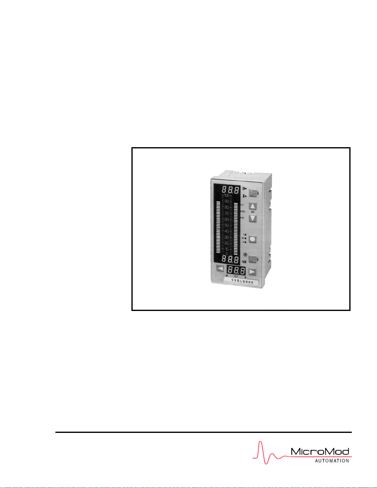
An illustration of the 53SL6000 controller that depicts the front display panel and the option modules
is provided in Figure 1-1.
1-1
Page 14
53SL6000 Instruction Manual Section 1. Introduction
1-2
Figure 1-1. 53SL6000 Controller
Page 15
Section 1. Introduction 53SL6000 Instruction Manual
1.2 Controller Model Numbers
The 53SL6000 controller model numbers are described in Table 1-1.
Table 1-1. 53SL6000 Model Numbers
53 SL6
Controllers
Design Designator
(includes analog inputs
1 and 2, analog output
1, discrete inputs 1 and
2, discrete outputs 1
and 2)
Power Requirements:
120/240 V ac 0
24 V dc 1
Option Slot A Module:
None 0
Single Universal Analog Input
(analog input 3)
Dual Universal Analog Input
(analog inputs 3 and 4)
(Each universal analog input can
accept RTD, thermocouple,
millivolt, voltage, and
frequency inputs. Thermocouple inputs are linearized
by this module.)
Option Slot B Module:
None.
53
♦♦♦A♦♦
SL6
1
2
0
Physical Ch ar a cte r is tic s
Weight
Front Dimension
Overall Length
< 1.5 kg (3 lb 5 oz)
72 x 144 mm
(2 53/64 x 5 43/64 in)
With Option Modules - 130.8 mm
(5.15 in)
Without Option Modules - 85.7
mm (3 3/8 in)
Panel Insta llat ion
Panel Cutout
Installation Depth
Mounting Position
See Figure 2-1
Allow an additional 25.4 mm (1
inch) for rear plug removal and
insertion.
Flush panel mounting ± 60
Degree of Pr ote cti on
Facial
Housing
NEMA4 (IP64)
NEMA1 (IP20)
Safety Classification
CSA
FM
Approved for Class 1,
Division 2 (planned).
FM Approved for Class 1,
Division 2 (planned)
°
2 Discrete Input/2 Discrete
Output (discrete inputs 3
and 4, discrete outputs 3
and 4)
Design Level A
Communications Mode:
None
RS-485 (allows datalink connection)
RS-232 (allows connection to a
personal computer or a modem)
Enclosure:
Standard Panel Mount Case
3
0
1
2
0
1.3 Product Specifications
The 53SL6000 controller conforms to the following
specifications and complies with the following regulatory requirements:
Environmental Limits
Operating Ambient
Temperature Limits
Storage/Transport
Ambient
Temperature Limits
-5 to 50°C (23 to 122° F)
-40 to 85°C (-40 to 185° F)
Relative Humidity Limits
Humidity Limits
(operation)
Humidity Limits
(storage/transport)
Barometric
Pressure
(operation)
Barometric
Pressure
(storage/transport)
Thermal Shock
(operation)
5 to 95%
5 to 100%
82.7 to 103.4 kPa
13.8 to 103.4 kPa
±
20°C/hr ( ± 68° F /hr)
1-3
Page 16

53SL6000 Instruction Manual Section 1. Introduction
Thermal Shock
(storage/transport)
Physical Shock
(operation)
Physical Shock
(storage/transmit)
Vibration point-to-point
constant
displacement
(operation)
Vibration
(storage/transport)
Corrosion
ESD
Transient Immunity
EM Emission
EMI Susceptibility
Surge Withstand
Capability
±
66°C/hr ( ± 150.8° F /hr)
15 g 1/2 sine, 11 ms
ASTM D4169, DC1
0.76 mm, 5 to 14 Hz
0.3 g, 14 to 200 Hz
ASTM D999
B 3-100 Hz
0.5 g
ISA S71.04, airborne contaminates G3 for 10 years.
IEC 801-2 8.0 kV
IEC 801-4,
power 4 kV direct,
signal 2 kV capacitively coupled
CISPR Pub. 11 Class A
SAMA PMC 33.1 - 1978
Class 3 - abc: no effect at 30 V/m,
at 27, 146, and 446 MHz;
IEC 801-3 10 V/m
ANSI C37.90a - 1974/IEEE
Standard 472 - 1974
Ring Wave: 1.5 MHz, 3 kV,
60 pulses/second for 2.0 seconds
Power Consumption
(no options
installed
transmitter supply
not in use)
Power Consumption
(options installed
transmitter supply
in use)
Permitted Voltage
Dips
8 W
15 W
≤
20 ms
Transmitte r Su pp ly
(referenced to power common)
Voltage Range
Ripple
On-Load Current
Pulsing Short
Circuit Current
24 V to 26 V
≤
200 mVp-p
≤
50 mA (short circuit protected)
50 mA
Analog Inputs 1 and 2
(referenced to power common)
Number
Rated Signal Range
(for each input)
Control Range
Input Impedance
2, non-isolated
0/4 to 20 mA
0 to 21.5 mA
250 ohm
AC Power
Voltage Range
Frequency Range
Power Consumption
(no options
Installed,
transmitter supply
not in use)
Power Consumption
(options installed
transmitter supply
in use)
Permitted Voltage
Dips
DC Power
Voltage Range
93.5 to 276 V ac
47 to 63 Hz
8 W/14 VA
20 W/36 VA
≤
20 ms
20 to 30 V dc
Filter Time Constant
Measurement Error
Temperature Effects
50 ms
≤ ±
0.02 mA
≤ ±
0.002 mA/°C
Discrete Inputs 1 and 2
(referenced to power common)
Number
Signal Low
Voltage
Signal High
Voltage
Input Impedance
Signal Low Contact
(closed)
Signal High Contact
(open)
2 (dry contacts or power contacts
up to 24 V dc)
0 to 1 V dc
4 to 24 V dc
1000 ohm
≤
100 ohms
≥
5000 ohms
1-4
Page 17

Section 1. Introduction 53SL6000 Instruction Manual
Analog Output 1
(referenced to power common)
Number
Rated Signal Range
Control Range
No-Load Voltage
Load Range
Filter Time Constant
Output Measurement
Error
Temperature Effects
1
0/4 to 20 mA
0 to 21.5 mA
≤
24 V
0 to 750 ohms
50 ms
≤ ±
0.02 mA
≤ ±
0.002 mA/°C
Discrete Outpu ts 1 and 2
(open drain tied to power common)
Number
2
(Contact ratings are for resistive
loads; transient suppression is required for reactive loads.)
Input Ranges (cont)
RTD - 3 or 4 wire connection (see
list)
Thermocouple (see list)
High/Low Level Input Specifications
Low Level Input High Level Input
Input Connection Differential Differential
Input Range:
Input Resistance: 10 Mohm 800 Kohm
Filter - 3db Point: 4.0 Hz no filter
Filter Response
(63%): 0.025 sec N/A
Normal Mode
Rejection:
Common Mode
Rejection: 160 db 160 db
Common Mode
Operating: 250 V rms 250 V rms
Normal Mode
Maximum: 250 V rms < 25 V
Conversion Type: Volts to
Resolution (17
bits plus sign): 2.5618 uV 0.1636 mV
Analog
Measurement
Error:
±
83 mV
24 db @ 60 Hz,
22 db @ 50 Hz
frequency
±
0.1% F.S.
±
25 ppm/°C
±
5.3 V
N/A
Volts to
frequency
±
0.1% F.S.
±
25 ppm/°C
Open (off)
Closed (on)
≤
1 mA leakage
2.0 V dc maximum voltage drop,
50 mA maximum operating current,
30 V dc maximum operating voltage, and
100 mA maximum short circuit
current
Universal Analog Input Option Module
(Isolated inputs, see Common Mode Rejection in
High/Low Level Input chart on next column)
Number
Update Rate
General Input Types
Input Ranges
Single: 1 input module,
Dual: 2 input module
300 msec
Low Level - mV, RTDs,
thermocouples
High Level - voltage, current,
frequency, pulse
1 to 5 V linear
1 to 5 V square root
0 to +5 V square root
0 to ±80 mV
Frequency input 8 Hz - 100 kHz
Frequency input 2.5 Hz - 100 kHz
Frequency input 0.5 Hz - 30 kHz
Pulse input (incremental sum)
0-100 kHZ
Frequency
Measurement Error
Frequency Input
Requirement
Pulse Measurement
Error
Thermocouple
CJC Measurement
Error
RTD List
Platinum RTDs
0.01%
Pulse, Square Wave:
+5 V, 5 usec-minimum
Sine, Triangular Wave:
10 V p-p
0%
Internal CJC
±2°
C
Platinum 100 Ohm RTD
= 0.003850
α
-
200° to +850° C
(-320° to 1560° F)
Platinum 100 Ohm RTD
= 0.003926
α
-
200° to +870° C
(-320° to 1590° F)
Platinum 100 Ohm RTD
= 0.003911
α
-200° to +850° C
1-5
Page 18

53SL6000 Instruction Manual Section 1. Introduction
Copper RTDs
Nickel RTDs
Thermocouple List
J
K
T
E
N
C
R
S
(-320° to 1560° F)
Copper 10 Ohm RTD
= 0.00427
α
-
200° to +260° C
(-320° to 500° F)
Copper 53 Ohm RTD
= 0.00427
α
-50° to +150° C
(-55° to 300° F)
Copper 100 Ohm RTD
= 0.00427
α
-100° to + 260° C
(-150° to 500° F)
Nickel 100 Ohm RTD
= 0.00618
α
-60° to +180° C
(-80° to 350° F)
Nickel 120 Ohm RTD
= 0.00672
α
-80° to +273° C
(-110° to 520° F)
Fe/Cu-Ni
-200° to +1200° C
(-325° to 2190° F)
Ni-Chrom/Ni-Al
-200° to +1370° C
(-320° to 2490° F)
Cu/Cu-Ni
-250° to +400° C
(-418° to 750° F)
Ni-Chrom/Cu-Ni
-260° to +1000° C
(−
436° to 1830° F)
Ni-14%Chrom-1.4%Si/Ni-4.4%Si
-0.1%Mg
-200° to +1300° C
(-320° to 2370° F)
Tungsten-5%Rhenium/Tungsten
-26%Rhenium
0° to +2320° C
(32° to 4200° F)
Pt-13%Rhodium/Pt
0° to +1765° C
(32° to 3200° F)
Pt-10%Rhodium/Pt
0° to +1765° C
(32° to 3200° F)
B
L
U
CHE
CHS
F
G
D
PLII
Pt-30%Rhodium/Pt-6%Rhodium
+20° to +1820° C
(68° to 3300° F)
Fe/Cu-Ni
-200° to +900° C
(-320° to 1650° F)
Cu/Cu-Ni
-200° to +600° C
(-325° to 1110° F)
Ni-Chrom/Cu-Ni (Chinese E)
-50° to +800° C
(-50° to 1470° F)
Pt-10%Rhodium/Pt (Chinese S)
0° to +1600° C
(32° to 2900° F)
0° to +1400° C
(32° to 2550° F)
Tungsten/Tungsten-26%Rhenium
20° to +2320° C
(68° to 4200° F)
Tungsten-3%Rhenium/Tungsten
-25%Rhenium
0° to +2320° C
(32° to 4200° F)
Au-Pt-Palladium/Au-Pall
(Platinel II)
-100° to +1395° C
(-140° to 2540° F)
2DI/2DO Option Module
Discrete Inputs
Signal Low, Voltage
Signal High, Voltage
Input Impedance
Signal Low Contact
Signal High Contact
Discrete Outputs
Contact Load
Life Expentancy
2
0 to 1 V dc
4 to 24 V dc
1000 ohms
≤
100 ohms
≥
5000 ohms (minimum
recognition 10 ms)
2 (Form C Relays)
250 V switching voltage,
≤
5 A switching current, and
≤
1250 VA-ac,
≤
30 W at 250 V dc, and
≤
100 W at 24 V dc
switching power
20,000,000 mechanical switching
operations and 2,000,000 electri-
1-6
Page 19

Section 1. Introduction 53SL6000 Instruction Manual
cal 24 V/4 A ohmic Amp switching
operations
Spark Suppressor
Electrical Isolation
CPU Cycle Time
Input Sample Rate
Output Update Rate
Display Update Rate
Control Ranges
Proportional (P)
Integral (I)
Derivative (D)
Display
Element Type
Digital Readouts
In series 5nF/51 ohm with varistor
420 Veff in parallel
1000 V contact coil
1000 V contact-contact
1000 V between relays
50 ms
50 ms
50 ms
1000% - 2%
200 min/repeat - 0.02 min/repeat,
0 is off.
8 min - 0.01 min, 0 is off
Red, green, and yellow LEDs
8.9 mm in height
Analog Bar Graphs
LED Indicators
Keypad
two 4 digit, 7 segment digital
readouts
one 3 digit, 7 segment digital
readouts
two columns of 40 LEDs
80.7 mm in height
4.8 mm in width
0 to 100% range
2.5% bargraph
operation resolution
red PV LEDs
green SP LEDs
twelve LEDs: red, green, yellow
Seven positive tactile-feel keys
1-7
Page 20

Section 2. Installation and Power-Up Procedures 53SL6000 Instruction Manual
2.0 Installation and Power-Up Procedures
rear of the controller so that it butts against the
2.1 Inspection
Inspect the equipment upon arrival for damage that
may have occurred during shipment. If damage is
such that faulty operation is likely to result, do not
install the controller and contact the MM Automation representative if purchased direct, or contact
the appropriate supplier for repair/replacement procedures. Inspect the packing material before discarding it to prevent the loss of any additional
product literature that may have been included in
the shipment. Also inspect the controller data tag
to ensure it has the correct power requirements for
the intended application (e.g., 120/240 V ac or 24 V
dc).
display flange. This step is optional and not
required.
The applicable option modules can be installed
2.
before each controller is mounted in the panel
cutout, or after mounting. If installing the option modules now, see Figure 2-7 to install the
universal analog input module, Figure 2-9 to
install the 2DI/2DO module, and Figure 2-12
to install the RS-232 or RS-485 module.
This step can be skipped if none of these modules were ordered with the controllers.
Slide each controller through the mounting col-
3.
lar and panel cutout. Secure each controller in
place using the two mounting brackets as
shown in Figure 2-1.
2.2 Site Location
The 53SL6000 controller is designed to operate on
a plant floor where the controller faceplate might be
exposed to occassional wash-downs. See Section
1.3 for the stated environmental specifications of
the controller.
2.3 Panel Mounting
Dimensions for single and multi-controller mounting in a single panel cutout are provided in Figure
2-1.
2.3.1 Single Cutout Installation
(NEMA4 Compliant)
From the rear of the controller, slide on the
1.
rubber O-ring so that it butts against the display flange.
The applicable option modules can be installed
2.
now, before the controller is mounted in the
panel cutout, or after mounting. If installing the
option modules now, see Figure 2-7 to install
the universal analog input module, Figure 2-9
to install the 2DI/2DO module, and Figure 212 to install the RS-232 or RS-485 module.
This step can be skipped if none of these modules were ordered with the controller.
Slide the controller through the panel cutout
3.
and secure it in place using the two mounting
brackets as shown in Figure 2-1.
2.3.2 Multiple Cutout Installation
Multi-controller mounting collar part numbers are
provided in Table B-1, Parts List.
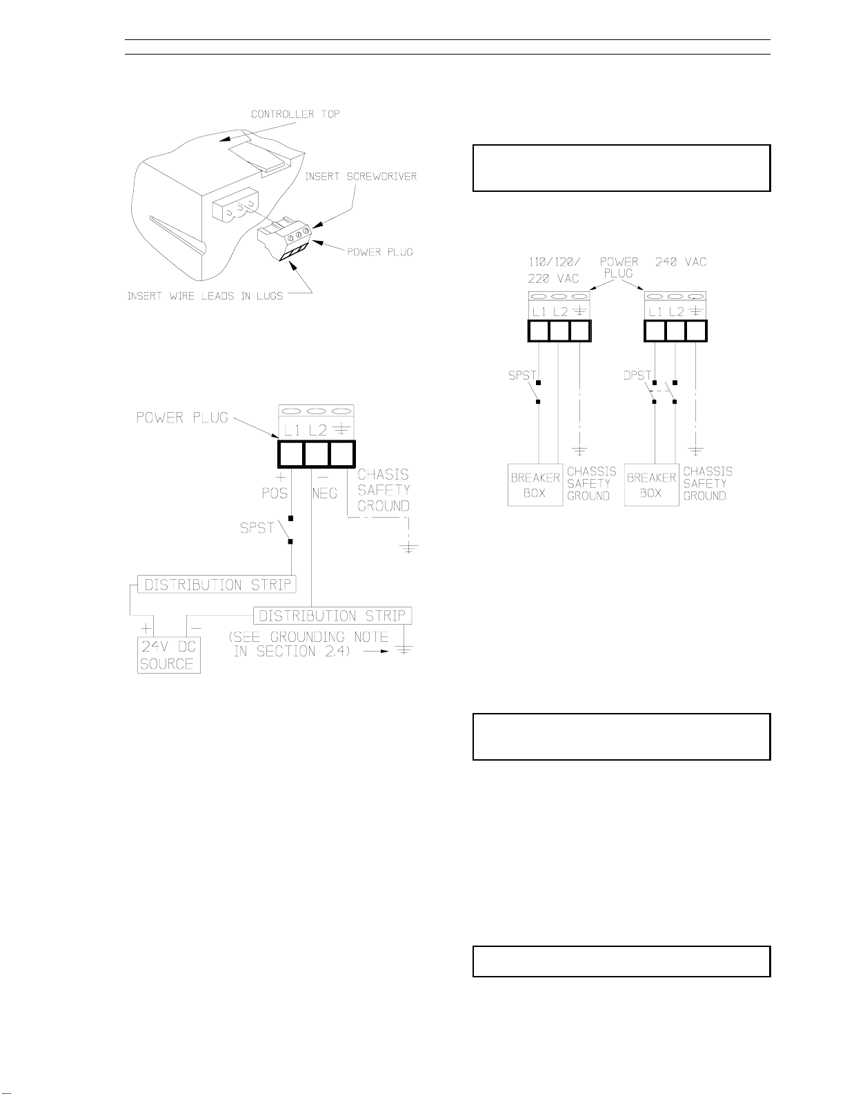
2.4 Power Connections
Figure 2-2 illustrates the power plug location on the
controller backplane. The power plug is removable
and can be pulled straight out from its backplane
connector. The plug is scalloped on one side to
ensure proper insertion after the power wires are
connected.
WARNING:
ac line service constitute a potential electric shock
hazard to the user; therefore, only qualified
technicians should install the unit. Make certain
that the ac power lines are disconnected from the
operating branch circuit before attempting
electrical connections.
NOTE:
to a high quality, noise-free point of earth
reference. Connection should be through a low
resistance (less than one ohm) lead wire directly
to the installation’s point of earth reference which
can be an independent grounding rod or ground
grid mesh that penetrates the permanent moisture
level below the frost line in accordance with Article
250 of ANSI/NFPA 70, the National Electrical
Code, or other code(s) acceptable to the authority
having jurisdiction over the installation.
NOTE:
signal wiring. Also, the power wiring should not
be routed in close proximity to signal wiring.
NOTE:
to expose 1/4 inch (6.4 mm) conductor.
Instruments that are powered from an
Installations are expected to have access
In electrically noisy locations, use shielded
Each power wire lead should be stripped
If it is desired to cushion the controller from the
1.
collar, then slide on the rubber O-ring from the
2-1
Page 21
2-2
53SL6000 Instruction Manual Section 2. Installation and Power-Up Procedures
Figure 2-1. Panel Cutout and Installation
Page 22
Section 2. Installation and Power-Up Procedures 53SL6000 Instruction Manual
Connect the chassis safety ground lug of the
3.
power plug to the ground wire.
NOTE: DO NOT APPLY POWER TO THE
CONTROLLER.
(Applying power is performed in Section 2.9.)
2.4.2 AC Power Connections
Figure 2-2. Power Plug
2.4.1 24 V DC Power Connections
Figure 2-3. 24 V DC Power Connections
Refer to Figure 2-3 to make the following connections:
Connect the positive (+) 24 V input line, via an
1.
SPST switch, to L1 of the power plug. As
shown in Figure 2-3, the positive input should
come from a distribution strip; do not daisychain the input power from one controller to
another. Leave the SPST switch in the OFF
position.
Connect the negative (-) input line to L2 of the
2.
power plug. As shown in Figure 2-3, the negative input should come from a distribution strip;
do not daisy-chain the negative input from one
controller to another. The distribution strip
should be connected to a noise free earth reference as shown in Figure 2-3.
Figure 2-4. AC Power Connections
Refer to Figure 2-4 to make the following connections:
For 110/120/220 V ac, connect the phase and
1.
neutral inputs to the power plug. For 240 V ac,
connect the two phase inputs to the power
plug.
Connect the chassis safety ground lug of the
2.
power plug to the ground wire (green, greenyellow).
NOTE: DO NOT APPLY POWER TO THE
CONTROLLER.
(Applying power is performed in Section 2.9.)
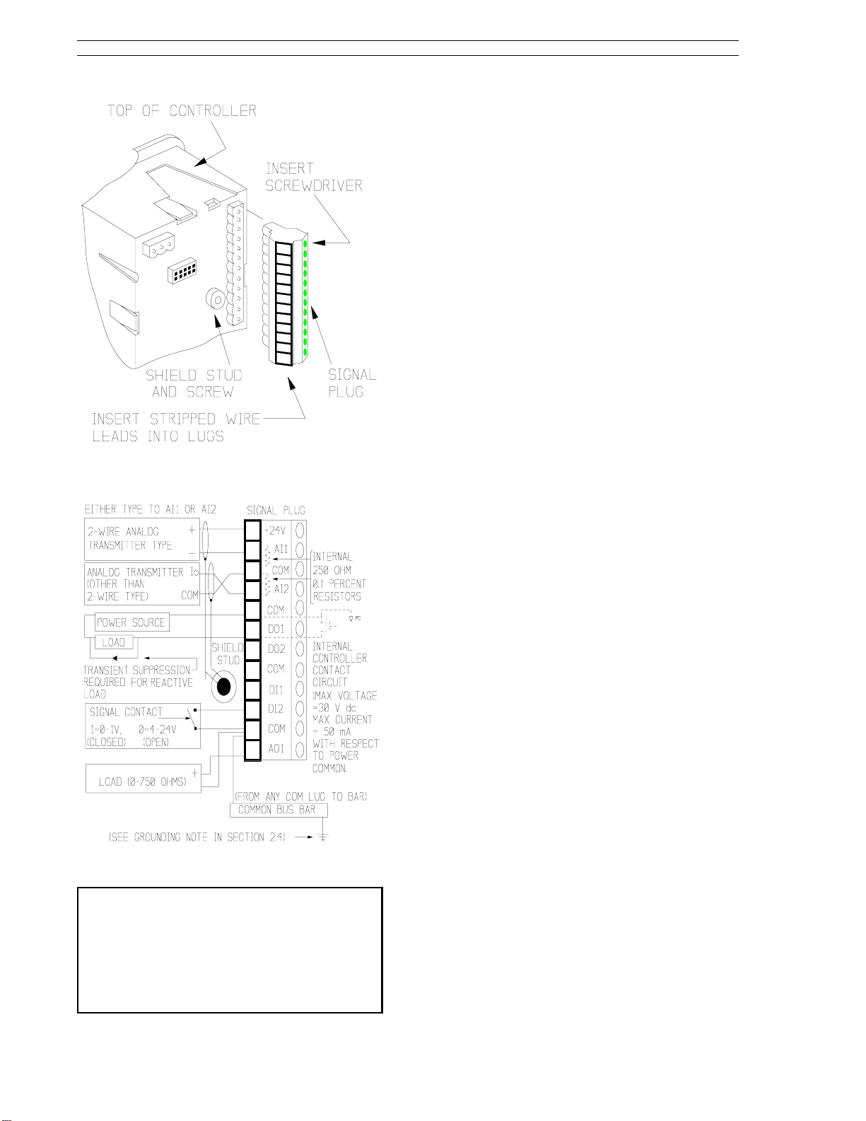
2.5 Signal Connections
Figure 2-5 illustrates the signal plug location on the
controller backplane. The signal plug is removable
and can be pulled straight out from its backplane
connector. The plug is scalloped on one side to
ensure proper insertion after the signal wires are
connected. Figure 2-6 illustrates the signal wire
connections.
Each signal wire lead should be stripped
NOTE:
to expose 1/4 inch (6.4 mm) conductor.
2-3
Page 23
53SL6000 Instruction Manual Section 2. Installation and Power-Up Procedures
2.5.1 Analog Inputs AI1 and AI2
In Figure 2-6, AI1 is connected to a transmitter that
requires power from the controller. Both, AI1
and/or AI2 can be connected to transmitters that
require controller power provided the total required
power does not exceed the specifications stated for
the transmitter supply in Section 1.3. The current
path for AI1 is from +24V to the + transmitter input,
through the transmitter element, out of the transmitter (-), to the AI1 plug connection, across the
internal 250 ohm (0.1%) voltage dropping resistor,
and down to Common.
In Figure 2-6, AI2 is connected to a transmitter type
that has its own power source and does not require
power from the controller. This transmitter type
can be connected to both AI1 and/or AI2. The
current path for AI2 is from the transmitter current
out (Io), to the AI2 plug connection, across the
internal 250 ohm (0.1%) voltage dropping resistor,
out the plug Common connection, to the transmitter
Figure 2-5. Signal Plug
Common connection.
Figure 2-6. Signal Plug Connections
NOTE 1:
be used in electrically noisy locations.
NOTE 2:
exceed the limit specified for the particular
transmitter (refer to the applicable technical
literature provided with the respective device).
NOTE 3:
connecting remote transmitters to the controller.
Shielded signal cable (two-wire) should
Signal transmission distance must not
Correct polarity must be observed when
Notice in Figure 2-6 that the signal cable shields
are connected to the backplane shield stud.
2.5.2 Discrete Outputs DO1 and DO2
Only DO1 is shown connected in Figure 2-6; connections to DO2 are identical. A discrete output
resistive load does not require transient suppression; however, reactive loads do to prevent coil
ringing or spiking from feeding back into the controller. The required diode shown as the suppression device is circuit dependent (typical: a 24V, 430
ohm, dc coil relay would require a 1N4003 diode).
2.5.3 Discrete Inputs DI1 and DI2
Only DI2 is shown connected in Figure 2-6; connections to DI1 are identical. In the figure, the
discrete input solid state circuitry is depicted as a
signal contact that opens or closes (logic states) in
response to input voltage levels (the discrete inputs
also work with dry contacts: ≤ 100 ohms is closed
and ≥ 5000 ohms is open).
2.5.4 Analog Output AO1
In Figure 2-6, the control output device is connected across the AO1 and COM lugs. Signal current passes from the AO1 connection, through the
device and back to Common. Control output device response to alter process operation is depenedent upon the analog signal amplitude.
2-4
Page 24
Section 2. Installation and Power-Up Procedures 53SL6000 Instruction Manual
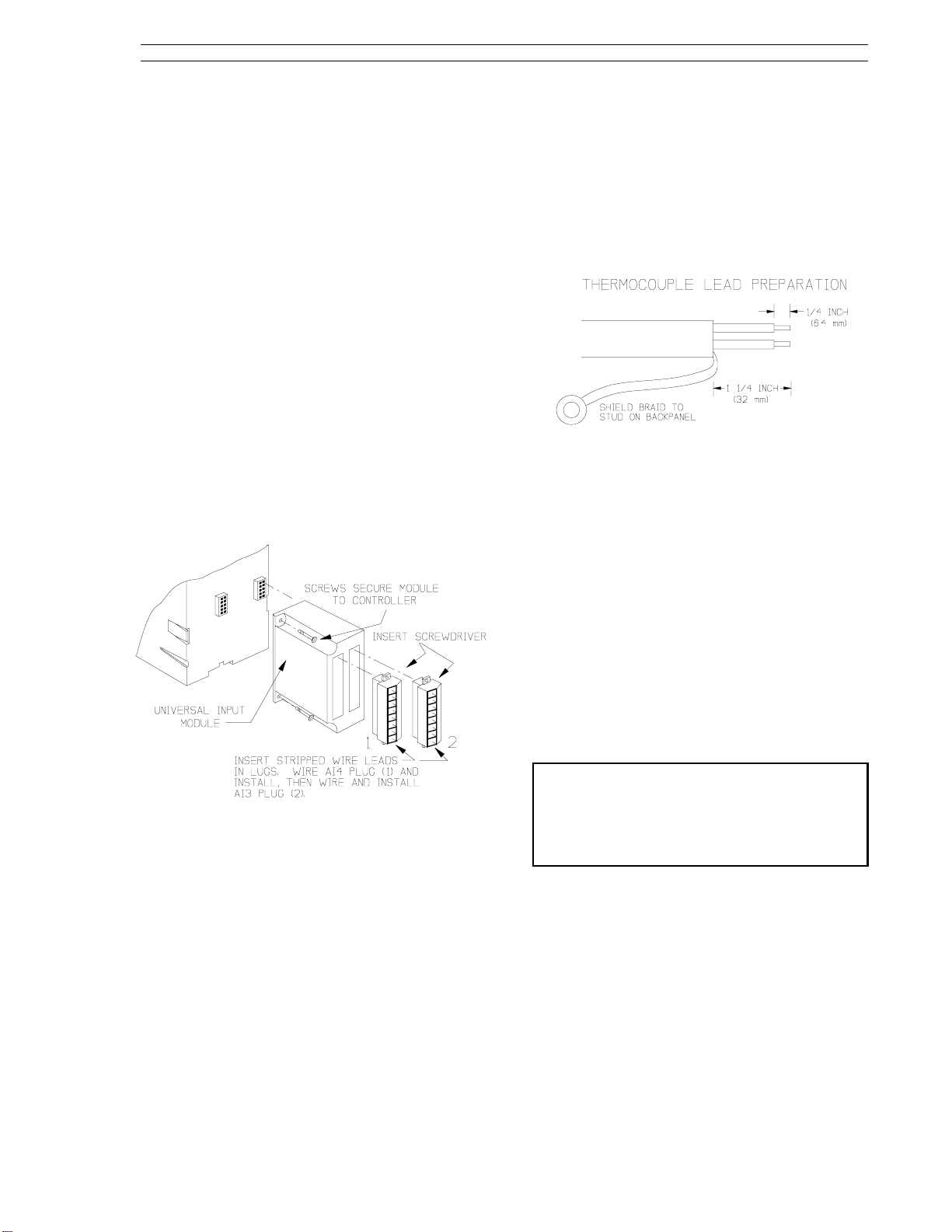
2.6 Universal Analog Input Module
This information applies to only those controllers
with an optional universal analog input module.
2.6.1 Universal Analog Input Module
Backplane Installation
Figure 2-7 illustrates the universal analog input
module location on the controller backplane. The
universal input module is socket mounted and is
secured to the backplane with two screws. Also
shown in Figure 2-7 are the signal plugs AI3 (right
plug) and AI4 (left plug) that are screw mounted to
the universal analog input module (the plug mounting screws are not illustrated). Depending on the
option ordered, one (AI3) or both (AI3 and AI4) of
these plugs will require installation and input connections. The plugs for AI3 and AI4 are identical;
therefore, care should be taken to ensure each
plug is installed in its proper location. Each plug,
however, is keyed to prevent inverted insertion into
its module connector.
2.6.2.1 Thermocouple Connections and
Burn-out Detection
To ensure proper cold junction compensation
(CJC) operation, the steps to wire a thermocouple
to the universal analog input module are as follows:
Prepare the thermocouple leads as shown in
1.
the following illustration:
For dual universal analog input modules that
2.
will have one thermocouple connected, ensure
it is installed on AI3 and that the other input is
installed on AI4.
For dual universal analog input modules that
3.
will have only one terminal plug connected, the
other terminal plug must still be installed on the
module for proper performance.
4. Thermocouple Burn-out Detection
shown in Figure 2-8, an open thermocouple
detection (OTD) current, which is very small, is
provided at pin 3 of each connector plug. If pin
3 is wired to pin 1 and the thermocouple opens,
then a positive temperature over range results.
If pin 3 is wired to pin 2 and the thermocouple
opens, then a negative temperature over range
results.
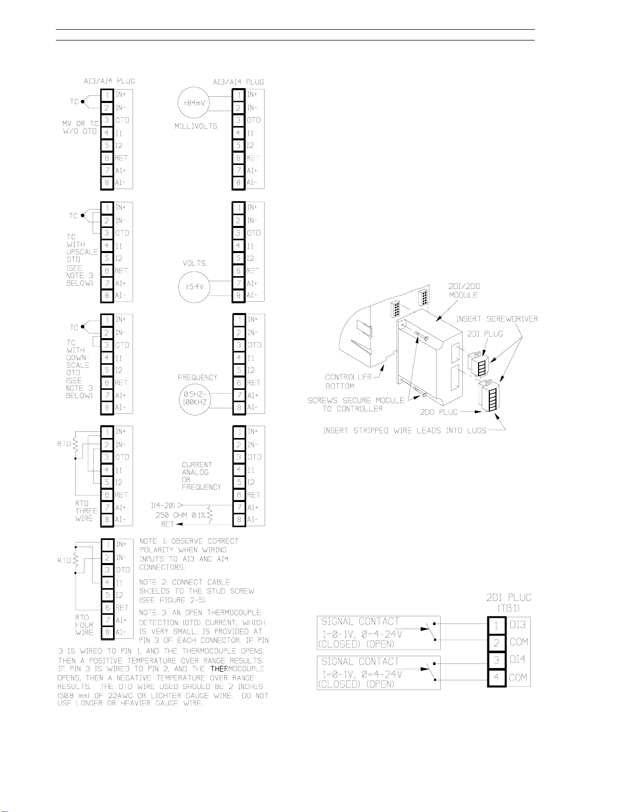
- As
Figure 2-7. Universal Analog Input Module
2.6.2 Universal Analog Input Module
Signal Wiring
As shown in Figure 2-7 (e.g., INSERT SCREWDRIVER), the signal wire lug screws are accessed
on the side of each plug.
Each analog input (AI3 and AI4) can accept only
one device input configuration as illustrated in Figure 2-8.
to another input.
Unused plug lugs can not be dedicated
NOTE: If an upscale or downscale open
thermocouple detection (OTD) wire is installed as
part of the thermocouple connection, then the wire
should be 2 inches (50.8 mm) of 22AWG wire or
lighter. Do not use longer or heavier gauge (e.g.,
14AWG) wire.
The complete assembly will reach thermal
5.
equilibrium approximately 30 minutes after the
controller is powered up (see Section 2.9, Applying Power).
2-5
Page 25
53SL6000 Instruction Manual Section 2. Installation and Power-Up Procedures
2.7 2DI/2DO Module
This information applies to only those controllers
with the optional 2DI/2DO module.
2.7.1 2DI/2DO Backplane Installation
Figure 2-9 illustrates the 2DI/2DO module location
on the controller backplane. The 2DI/2DO module
is socket mounted and is secured to the backplane
with two screws. Also shown in Figure 2-9 are the
2DI and 2DO signal plugs that are screw mounted
to the module (the plug mounting screws are not
illustrated). The two plugs are different in size;
therefore, they can not be inadvertently installed in
the wrong sockets and each plug is keyed to prevent inverted insertion into its module socket.
Figure 2-8. Input Configurations
Figure 2-9. 2DI/2DO Module
2.7.2 2DI/2DO Signal Wiring
As shown in Figure 2-9 (e.g., INSERT SCREWDRIVER), the lug adjusting screws are accessed
on the side of the plug.
Signal input connections for the 2DI four terminal
plug are illustrated in Figure 2-10. The functional
description for DI3 and DI4 is identical to that described in Section 2.5.3 for DI1 and DI2.
Figure 2-10. 2DI Plug Connections
2-6
Page 26
Section 2. Installation and Power-Up Procedures 53SL6000 Instruction Manual
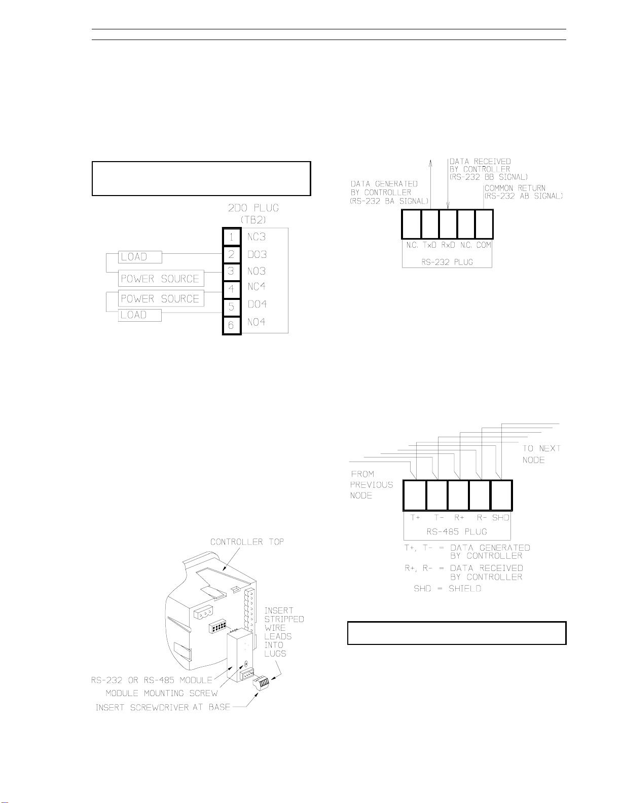
Signal input connections for the 2DO six terminal
plug are illustrated in Figure 2-11. Both, DO1 and
DO2 are Form C relays. The contact load capacities are 250 V ac or 250 V dc maximum switching
voltage; 5 A switching current; 1250 VA-ac maximum, and 30 W at 250 V-DC maximum or 100 W at
24 V-DC maximum switching power.
The 2DI/2DO module provides line
NOTE:
suppression; appropriate load suppression must
be supplied by the user.
Figure 2-11. 2DO Plug Connections
2.8 RS-232 and RS-485 Modules
This information applies to only those controllers
with the optional RS-232 module or RS-485 module.
2.8.1 RS-232 Plug Connections
Signal connections to the RS-232 module plug are
illustrated in Figure 2-13. Transmitted (TxD) and
received (RxD) signals are with respect to the controller.
Figure 2-13. RS-232 Plug Connections
2.8.2 RS-485 Plug Connections
Signal connections to the RS-485 module plug are
illustrated in Figure 2-14. In the illustration, the
controller is shown wired as a drop on the datalink.
Two wires are therefore connected to each lug:
one set (T+, T-, R+, R-, SC) that comes from the
previous node and another set that is connected to
the next datalink node.
Figure 2-12 illustrates the RS-232 module or the
RS-485 module location on the controller backplane. The module is socket mounted and is secured to the backplane with a screw. Also shown in
Figure 2-12 is the module signal plug, which is
keyed to prevent inverted insertion in its socket.
As shown in Figure 2-12 (e.g., INSERT SCREWDRIVER AT BASE), the lug adjusting screws are
accessed at the bottom of the plug.
Figure 2-12. RS-232 or RS-485 Module
Figure 2-14. RS-485 Plug Connections
Cable shield should be connected to
NOTE:
ground at only one location.
2.9 Applying Power
Verify all controller connections and ensure each
connection is mechanically sound before closing
the power switch to apply controller power. The
2-7
Page 27

53SL6000 Instruction Manual Section 2. Installation and Power-Up Procedures
controller powers up in the last state it was in before power was removed.
2.9.1 Power-up Sequence
The power-up sequence is as follows:
At power-up, the controller performs a power-
1.
on self test which includes lighting all faceplate
LEDs for three seconds to show they are working.
After completing the power-on self test, status
2.
information is presented in the dros. During
status, both of the vertical bars have five
equally spaced LEDs lit.
If the power-on self test is successful, the
2a.
dros will contain option identification
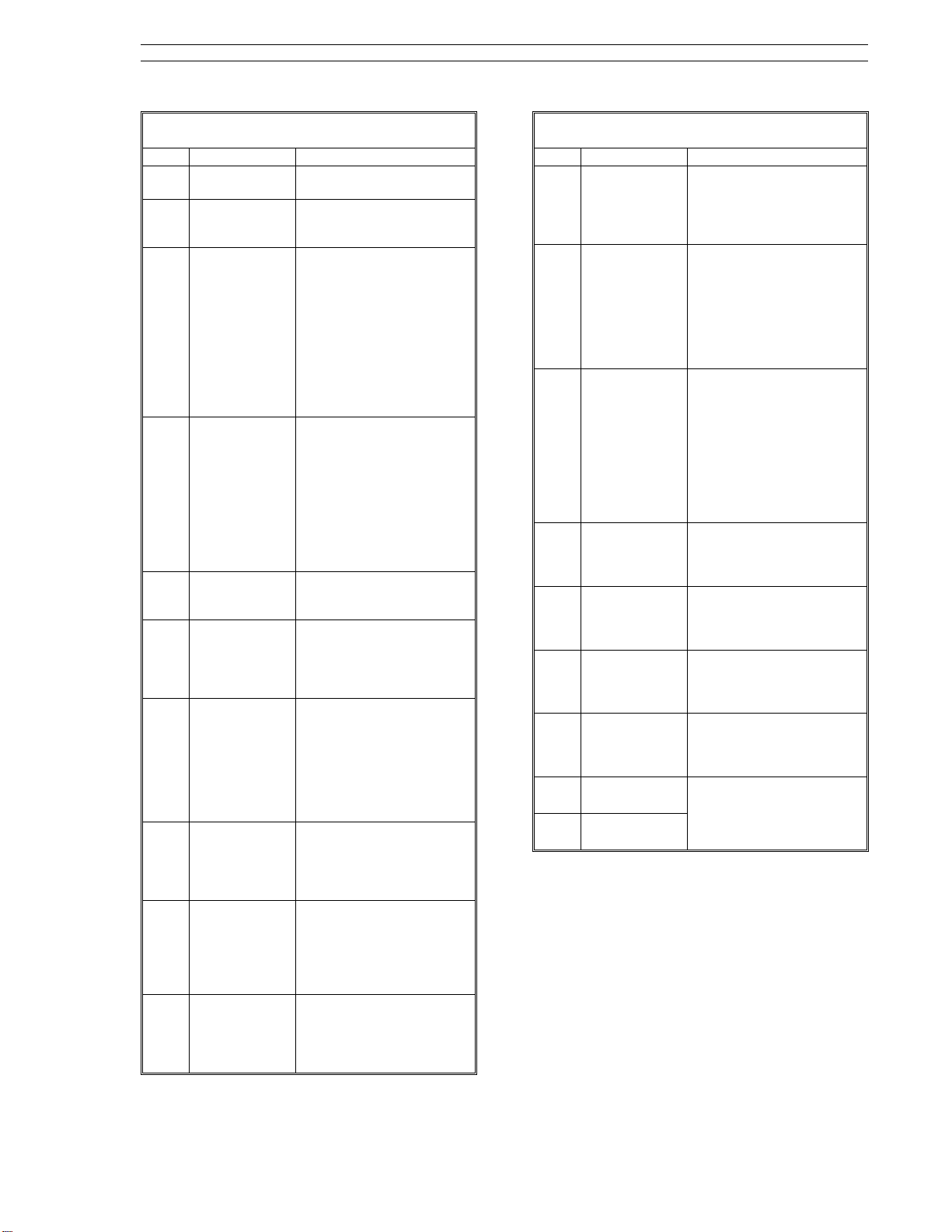
codes and the firmware revision level identification for the next three seconds as described in Table 2-1.
Table 2-1. Controller Status Codes
dro Attribute Status Code
Top (red) Option A status
Middle
(green)
Bottom
(yellow)
code.
Option B status
code.
Firmware revision
level identifier.
0 = no options.
192 = 2DI/2DO.
193 = Single Universal Analog Input.
194 = Dual Universal Analog Input.
Code must be cross
referenced to
revision level.
controller confidence tests when it was powereddown. Both vertical bars and all status indicator
LEDs, except the WD indicator, will be lit during the
controller confidence test execution.
If a power-on self-test database memory
2b.
error occurs, the
error appears in
nrAM
the top (red) dro and the controller halts
further operation. Return unit to for
service
After a successful power-on self test and
3.
status presentation, the controller enters operator mode, unless it was offline or executing
the controller confidence test when it was powered-down.
Offline is indicated by four equally spaced
pairs of lit LEDs in the green vertical bar.
When offline, no control is being performed
and all outputs are held at their values previous to being placed in offline mode. (For
more information about operator mode see
Section 3.2, Operator Mode; for more information about the offline state, see Section 3.7,
Offline Display Pattern.)
Reference Section B.4.6, Exiting the Controller
Confidence Test via the Faceplate Push Buttons, if
it is suspected that the controller was executing the
2-8
Page 28
Section 3. Display Panel 53SL6000 Instruction Manual
3.0 Display Panel
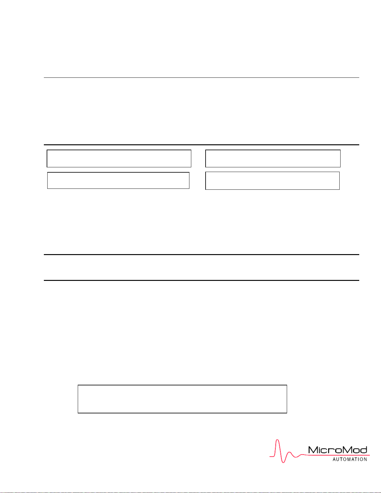
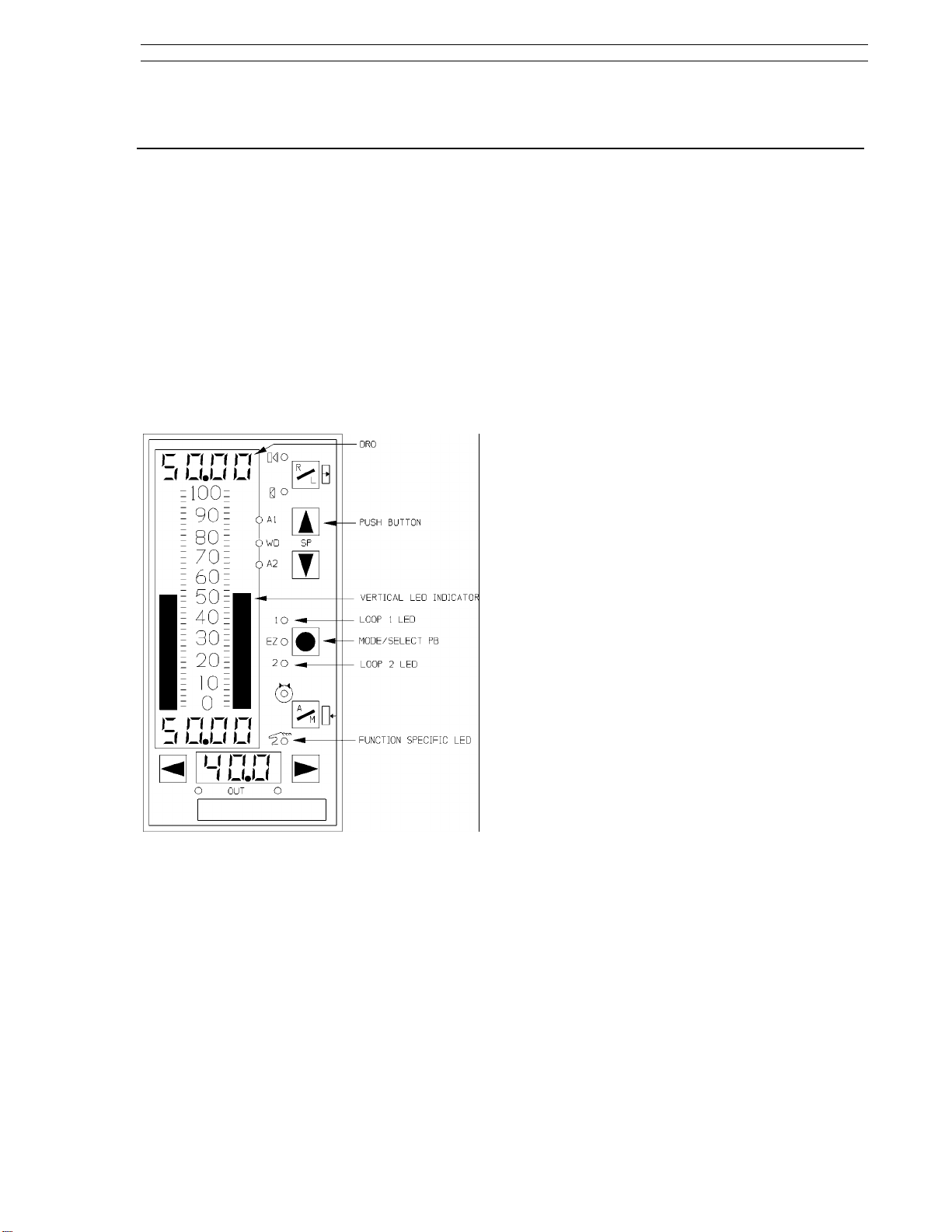
3.1 Display Panel Overview
As shown in Figure 3-1, the controller display panel
contains three digital read-out (dro) fields, two vertical bar indicators, twelve function specific status
indicators, and seven push buttons (pbs). The display panel is used to alter controller settings (which
in turn affect process operation), to monitor process operation, and to configure controller functionality. (It is also used to commission the controller,
which is described in Section 9.) Process operation is altered and monitored with the controller in
operator mode; controller functionality is configured with the controller in engineer mode.
The red display area includes the left vertical
Red:
bar, upper dro, and alarm status indicators (A1,
A2). This display area is assigned to the process
variable input. The red vertical bar indicates the
process variable as a percent of control range and
the red dro is the process variable in engineering
units.
Green:
vertical bar, the dro immediately beneath it, the
remote/local pb with its two status indicators, and
the setpoint up/down pbs. This display area is usually assigned to setpoint indication and control, although the green vertical bar and dro can be used
to indicate a second process variable if the selected control scheme is an indicator. The green
vertical bar indicates the setpoint as a percent of
control range and the green dro is the value in
engineering units.
Yellow:
tom dro, the auto/manual pb with its status indicators, the output pbs, and the two multistate (MS1,
MS2) indicators. This display area is primarily assigned to output indication and control. The yellow
dro is an output value in percent of the scaled final
control element travel range.
The green display area includes the right
The yellow display area includes the bot-
Figure 3-1. Display Panel Overview
3.2 Operator Mode
The colors red, green, and yellow are used to visually partition the display panel into general operating mode functional areas as follows:
red - process variable presentation.
•
green - setpoint presentation and control.
•
yellow - output presentation and control.
•
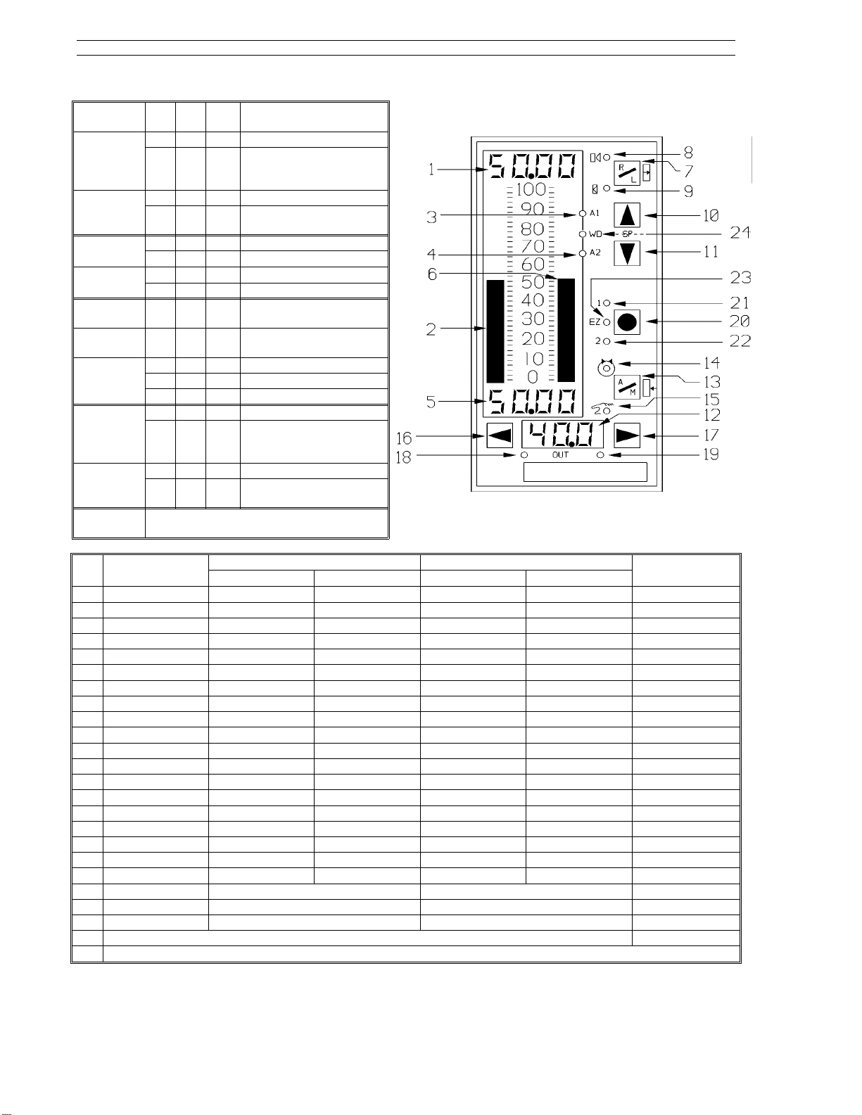
3.2.1 Operator Mode Panel Functions
The operator mode panel functions are described
in Figure 3-2 on the next page. The figure has
three major parts: an illustration of the controller
with item number call-outs in the upper right, a
supporting chart in the upper left that defines the
Off/On/Blinking status indicator states, and a summary chart at the bottom that lists the assigned
functions of each item call-out by control scheme.
The illustration item call-outs are defined in more
detail in Table 3-1.
As shown in Figure 3-2, many of the push buttons
and status indicators have identical functions in the
different control schemes; however, the indicator/loader (in.Ld) control scheme is the most
unique.
3-1
Page 29
53SL6000 Instruction Manual Section 3. Display Panel
Item/LED Off On Blink-
8 - R X Remote/Ratio.
9 - L X Local Setpoint.
3 - A1
4 - A2
24 - Watch dog
21 - Loop 1 X Loop 1 selected (cASc,
22 - Loop 2 X Loop 2 selected (cASc,
23 - Easy Tune
14 - Auto X In Auto.
15 - Manual X In Manual.
18, 19 MS1, MS2
X No alarm.
X Normal operation.
X Not running Easy-Tune.
Alternately on/off for time proportioned
or three step output.
ing
X Remote requested, but
X Setpoint is tracking the
XAlarm active.
XOut of service.
XFailed Easy-Tune.
X Running Easy-Tune.
X Auto requested but not
X Output is tracking the
Description
not granted (Remote
Enable [RE] not true).
SP tracking signal.
L.LiM, h.LiM).
L.LiM, h.LiM).
granted - (Auto Enable
[AE] not true.)
Force Output signal.
Item SnGL
1 PV dro PV dro PV dro PV dro PV dro PV(1) dro
2 PV bar PV bar PV bar PV bar PV bar PV(1) bar
3 PV Alarm 1 status PV Alarm 1 status PV Alarm 1 status PV Alarm 1 status PV Alarm 1 status PV(1) Alarm 1
4 PV Alarm 2 status PV Alarm 2 status PV Alarm 2 status PV Alarm 2 status PV Alarm 2 status PV(1) Alarm 2
5 Setpoint* dro Setpoint* dro Setpoint dro Setpoint* dro Setpoint dro Auto/PV2 dro
6 Setpoint bar Setpoint bar Setpoint bar Setpoint bar Setpoint bar Auto/PV2 bar
7 R/L pb R/L pb N/A R/L pb N/A N/A
8 Remote LED Remote status N/A Remote status N/A N/A
9 Local LED Local status N/A Local status N/A N/A
10 SP Up pb SP Up pb SP Up pb SP Up pb SP Up pb N/A
11 SP Down pb SP Down pb SP Down pb SP Down pb SP Down pb N/A
12 Out dro Out dro Out dro Out dro Out dro Auto/PV2 Xmt dro
13 Auto/Manual pb Auto/Man. pb Auto/Man. pb Auto/Man. pb Auto/Man. pb Auto/Manual pb
14 Auto LED Auto status Auto status Auto status Auto status Auto status
15 Manual LED Manual status Manual status Manual status Manual status Manual status
16 Decrease Out pb Decr. Out pb Decr. Out pb Decr. Out pb Decr. Out pb Decrease Out pb
17 Increase Out pb Incr. Out pb Incr. Out pb Incr. Out pb Incr. Out pb Increase Out pb
18 Multistate 1 Multistate 1 N/A Multistate 1 N/A Multistate 1
19 Multistate 2 Multistate 2 N/A Multistate 2 N/A Multistate 2
20 Mode pb Mode pb, Loop 1/2 Select pb Mode pb, Loop 1/2 Select pb Mode pb
21 N/A Loop 1 select Loop 1 select N/A
22 N/A Loop 2 select Loop 2 select N/A
23 Easy-Tune status N/A
24 Watchdog condition indicator
Control
Secondary (L1) Primary (L2) Primary (Loop 1) Limiting (Loop 2)
cASc Control L.LiM/h.LiM Control in.Ld
PV(1)=PV/PV1
*Ratio based on conF-cn.1-SPM setting.
Figure 3-2. Operator Mode Display Panel Summary
3-2
Page 30
Section 3. Display Panel 53SL6000 Instruction Manual
Table 3-1. Operator Mode Display Items
Item Call-Out Description
1 PV dro It is the process variable
2 PV bar It indicates the process
3PV Alarm 1
Status
4PV Alarm 2
Status
5 Setpoint dro It is the setpoint value in
6 Setpoint bar It indicates the setpoint
7R/L
Push
Button
8Remote
Setpoint
Status
9Local
Setpoint
Status
10 Setpoint
Up
Push
Button
value in engineering units.
variable percent of control
range.
When active, it indicates
alarm 1 of the selected
alarm index limits (e.g.
high/low alarms; high, highhigh alarms; etc.) was not
within tolerable limits.
For high/low alarms, an
active Alarm 1 LED
indicates the the PV
exceeded the high
alarmed value.
When active, it indicates
alarm 2 of the selected
alarm index limits (e.g.
high/low alarms; low, lowlow alarms; etc.) was not
within tolerable limits. For
high/low alarms, an active
Alarm 2 LED indicates the
PV fell below the low
alarmed value.
engineering units or a ratio
setpoint.
percent of control range.
It also produces a striped
pattern when the
controller is offline.
Generally, it is used to
select the setpoint source:
remote or local setpoint
control. Remote setpoint
control requires an active
Remote Enable. For ratio
control, it is used to select
ratio or standard control.
It indicates remote
setpoint is selected with
the R/L push button. See
item 7 above and the LED
chart in Figure 3-2.
It indicates the local or
tracking setpoint is
selected with the R/L push
button. See item 7 above
and the LED chart in Figure
3-2.
Pressing this push button
increases the local
setpoint or ratio setpoint
value. See Table 3-2 for
setpoint mode selections.
Table 3-1. Operator Mode Display Items
Item Call-Out Description
11 Setpoint
Down pb
12 Out dro It is the control output as a
13 A/M
Push
Button
14 Auto
Status
15 Manual
Status
16 Decrease Out
Push
Button
17 Increase Out
Push
Button
18
Multistate 1
Indicators
19
Multistate 2
Indicators
Pressing this push button
decreases the local
setpoint or ratio setpoint
value. See Table 3-2 for
setpoint mode selections.
percent of control range.
It can also be used to
display an externally
generated signal such as a
proportional speed
floating control valve
position indication.
It is used to select auto or
manual control. If auto is
selected and Auto Enable
is active, then the output is
determined by the
controller PID algorithm. If
manual is selected, the
output is determined by
the decrease/increase out
push buttons.
It indicates auto operation
is selected with the A/M
push button. See the LED
chart in Figure 3-2.
It indicates manual
operation is selected with
the A/M push button. See
the LED chart in Figure 3-2.
When in manual
operation, pressing this
push button causes the
output to decrease.
When in manual
operation, pressing this
push button causes the
output to increase.
These two indicators
activate to show the
direction of the discrete
control output.
3-3
Page 31

53SL6000 Instruction Manual Section 3. Display Panel
Table 3-1. Operator Mode Display Items
Item Call-Out Description
20
Select Mode
and Loop 1/2
Push Button
Pressing this push
button in operator
mode with an active
two loop control
scheme (cASc, L.LiM, or
h.LiM) selects the loop
under display panel
control. It toggles from
one loop to the other
each time it is pressed.
If this push button is
held for three seconds,
it causes engineer
mode to be entered.
Pressing it in engineer
mode causes a return
to operator mode.
21
22
Loop 1
Select
Indicator
Loop 2
Select
Indicator
These indicators are for
the two loop control
schemes cASc, L.LiM,
and h.LiM. Either one
of these two indicators
will activate to show
which loop is under
display panel control
as selected by the
Mode push button.
23
Easy-Tune
Status
This status indicator
blinks during Easy-Tune
operation. A steadystate-on condition
indicates Easy-Tune
terminated with an
error. It stops blinking
when Easy-Tune
completes successfully.
24
Watchdog
Condition
Indicator
This indicator activates
whenever the
controller detects an
internal processor
failure. When active,
all outputs are forced
to their power-off state.
Attempt to restart the
controller by cycling
power.
Table 3-2. Setpoint Up/Down Push Buttons
Display Panel Action
Alter standard SP value. Y Std
No SP control. Y Std
Alter standard SP value. Y K-SP
Alter ratio SP value. Y K-SP
R/L PB (7)
R LED
(8)
L LED
(9)
SPM*
*SPM settings (Std or K-SP) are made in engineer
mode, which is described later in Section 3.
3.3 Auxiliary Operator Access
To facilitate operator access for auxiliary data input
and selected parameter modification, an engineer
mode oPEr menu is provided. This menu allows
display panel entry of logical and analog signal
constants, process variable alarm values, high/low
output limit values, and PID values. It also provides operator capabilities to execute the EasyTune sequence. Access to menu items is
controlled through the conF-oPr enabling parameters. Because the oPEr menu parameters and their
corresponding conF-oPr enabling parameters are
accessed in engineer mode, they are described in
Tables 3-3 and 3-4, which appear later as part of
the engineer mode information.
3.4 Operator Mode Overflow/ Underflow Indication
Overflow indicators are plus signs (+) and underflow indicators are negative signs (-). Illustrations
of the overflow and underflow conditions are provided in Figure 3-3. They appear in the affected
dro and are decimal point sensitive. If these indicators repeatedly appear, the decimal point should be
repositioned with the conF-cn.1(cn.2)-dP parameter described in Table 7-3. Adjusting this parameter requires knowledge of engineer mode, which is
described next in this section.
3-4
Figure 3-3. Overflow/Underflow Indicators
Page 32

Section 3. Display Panel 53SL6000 Instruction Manual
mon parameters such as alarm limits,
3.5 Engineer Mode
The controller parameters and path connections
are configured in engineer mode. Engineer mode
is also used to initiate the Easy-Tune sequence
(see Section 9.8). This mode is entered when the
mode push button is held pressed for an extended
period of approximately 3 seconds, at which time
the oPEr menu prompt appears in the green dro.
3.5.1 Engineer Mode Display Panel
The display panel functions for engineer mode are
described in Figure 3-4 as follows:
• Level 2, Module Select - used to select a spe-
• Level 3, Parameter Select - used to select a
• Level 4, Edit - this is where a value is entered
deadband, etc. (This path skips level 2,
module described below.)
ProG (Program) - is selected to enter reg-
2.
ister values, formula constants, and to
make path connections. Parameters entered in this menu will force the controller
offline. It is used primarily by engineering
personnel.
conF (Configure) - is selected to configure
3.
online database parameters; it is used primarily by engineering personnel.
cific controller functional element (e.g., the
prompt Ai.1 for analog input 1). The full path
name is indicated by menu-module (e.g., conFAi.1). The module selection is skipped in the
oPEr menu path.
specific parameter from a list of module parameters (e.g., the parameter prompt SPAn under Ai.1). The full path name is indicated by
menu-module-parameter (e.g., conF-Ai.1SPAn).
for the displayed parameter or a selection from
a list of values or mnemonics is made.
Figure 3-4. Engineer Mode Display Panel
3.5.2 Engineer Mode Hieracrhical
Structure
Engineer mode is a hierarchical structure of nested
prompt layers that can be four levels deep; the
general order of selection is:
• Level 1, Menu - After engineer mode is accessed with the mode push button, each menu
prompt can be displayed sequentially by pressing the scroll forward pb. The menu prompts
are three major display panel paths: oPEr,
ProG, and conF. The ProG and conF paths
can each be protected with their own unique
pass-key. The three menu prompts are described as follows:
oPEr (operator) - provides quick access
1.
for operators to display and configure com-
3.5.2.1 Editing a Parameter
Figure 3-5 illustrates the steps to edit a parameter
in engineer mode. In the illustration a parameter
selection is made; some parameters require a numeric value to be entered. The process to edit a
parameter is reiterative:
• When engineer mode is entered, the oPEr
menu prompt (level 1) appears in the green
dro. The menu prompts are scrolled and one
is selected.
• Selecting a menu prompt causes the first module prompt (level 2) to appear in the yellow dro.
The module prompts of the selected menu are
scrolled and one is selected.
• Selecting a module prompt causes the first parameter prompt (level 3) to appear; it replaces
the menu prompt in the green dro. The parameter prompts of the selected module are
scrolled and one is selected.
• Selecting a parameter prompt causes the first
edit entry prompt (level 4) to appear in the red
dro. An edit input list is scrolled and an item is
selected or a numeric value is entered.
3-5
Page 33

53SL6000 Instruction Manual Section 3. Display Panel
NOTE 1:
occurs if a parameter prompt is not selected in
engineer mode.
NOTE 2:
affect immediately. If a ProG menu parameter is
edited, the controller goes to the offline condition
in which no control action is performed.
There is a 12.5 second time-out that
oPEr and conF parameter changes take
3.5.2.2 Deselecting and Scrolling
Backward
Figure 3-6 illustrates how to move through the various modules and their parameters by using the
deselect and scroll backward push buttons. Figure
3-6 begins with the last level 4 edit select step in
Figure 3-5 where the bASE parameter of the Ai.2
module was updated. The object in Figure 3-6 is to
exit the Ai.2 module after the bASE parameter has
been updated and to access the Ai.1 module where
any one of its parameters can be scrolled and selected for updating.
3.5.2.3 Editing a Numeric Value
If a parameter value must be entered in the red dro,
different editing steps must be performed than
when a selection is made from an item list. Figure
3-7 illustrates these steps; it assumes engineer
mode has been entered, and the menu, module,
and parameter have been selected. The parameter
conF-Ai.1-SPAn will be edited from 100.0 to 275.0.
Only the red dro showing the conF-Ai.1-SPAn
value appears in the illustration.
Figure 3-5. Editing a Parameter
Figure 3-8 illustrates changing the conF-Ai.1-SPAn
value from 100.0 to 10.00 by moving the decimal
point. It assumes engineer mode has been entered, and the menu, module, and parameter have
been selected.
3-6
Page 34

Section 3. Display Panel 53SL6000 Instruction Manual
Figure 3-6. Deselecting and Scrolling
Backward
Figure 3-8. Moving the Red dro Decimal
Point
3.5.2.4 Editing the Tag Parameter
The tAG is one parameter where an alphanumeric,
rather than a numeric, can be entered. It occurs
when the datalink controller conF-SYS-tAG parameter must be configured. Because four characters maximum can be displayed at any one time in
the red dro, using the shift right push button in
engineer mode allows the ten character positions
to be displayed as follows:
The bold characters are those that can be changed
with each four position display.
Characters are selected for each position with the
scroll forward/backward push buttons in a manner
described in Figure 3-7. The procedure to edit the
tag is described in Figure 3-9. It assumes the
conF-SYS-tAG parameter is already accessed.
0123
→ 3
456
→ 6
789
Figure 3-7. Editing a Red dro Value
3-7
Page 35

53SL6000 Instruction Manual Section 3. Display Panel
Press the scroll forward pb until the desired
1.
number for the first digit appears (assumes
first digit is not a zero).
Press the position select right pb; the second
2.
zero starts blinking.
Repeat steps 1 and 2 to enter all four pass-key
3.
digits.
Press the enter pb; if the pass-key is correct
4.
engineer mode functions are permitted for that
menu.
If the pass-key can not be recalled, then
NOTE:
the database must be defaulted using the
procedure described in Section B.5.
Figure 3-9. Editing a tAG
3.6 Entering a Pass-Key
In engineering mode, access to the ProG and conF
menus can be selectively restricted, as each menu
has its own pass-key capabilities. A pass-key is a
four digit number that must be entered when a
menu is selected; otherwise, access to module
prompts in that menu are prohibited. Figure 3-10
illustrates the key display that appears if a menu is
pass-key protected.
3.6.1 Configuring a Pass-Key
To configure a conF (or ProG) pass-key, the following steps must be performed:
Enter engineer mode by pressing and holding
1.
the mode pb until a menu prompt appears in
the green dro.
Press the scroll forward pb until conF (ProG)
2.
appears in the green dro.
Press the enter pb to accept the conF (ProG)
3.
menu.
If KEY does not appear in the yellow dro, press
4.
the scroll forward pb until it does.
Press the enter pb to select the KEY prompt.
5.
cKEY (PKEY) appears in the green dro.
It is assumed the pass-key was never configured before and that four zeros appear in the
red dro:
Press the enter pb; the leftmost number (zero)
6.
in the red dro blinks.
Press the scroll forward pb until the desired
7.
number appears (assumes zero will be
changed to a different number).
Press the shift right pb; the next zero starts
8.
blinking.
Repeat steps 7 and 8 until all four pass-key
9.
digits are entered.
Press the enter pb to enter the pass-key.
10.
Press the mode pb to exit engineer mode.
11.
Figure 3-10. KEY? Prompt
The correct pass-key must be entered in the red
dro with the following procedure:
3-8
3.7 Offline Display Pattern
The controller offline state is indicated by four activated double LED markers along the green vertical
bar as shown in Figure 3-11. The remainder of the
vertical bar is dark.
Events that can cause the controller to be offline
are as follows:
• If a ProG menu parameter is altered in engineer mode , it causes the controller to immediately go offline,
Page 36

Section 3. Display Panel 53SL6000 Instruction Manual
• If exiting the conF or ProG menus in engineer
mode, the controller goes offline and a blinking
oFF prompt appears in the red dro immediately
after the mode pb is pressed. To put the controller in operator mode, press the scroll forward pb to change the oFF prompt to the run
prompt and press the enter pb.
• The controller may have been powered-down
in offline, in which case it will return to offline
after the status and power-on self test se-
3.8 Engineer Mode oPEr Selections
This menu provides operator access to selected
parameters and auxiliary inputs. Items not enabled
from the oPr module of the conF menu will not
appear in the oPEr menu. The oPEr parameters
and auxiliary inputs are described in Table 3-3 and
their enabling parameters are described in Table
3-4 as follows:
quence is complete. To put the controller in
operator mode if an offline indication occurs
after the power-up sequence, perform the following steps:
press and hold the mode pb until a menu
1.
item (conF, oPEr, or ProG) appears.
Use the scroll forward push button to dis-
2.
play the ProG or conF menu prompts and
press the select push button.
Press the mode pb; the oFF prompt ap-
3.
pears blinking in the red dro.
To put the controller in operator mode,
4.
press the scroll forward pb to change the
oFF prompt to the run prompt and press
the enter pb.
Figure 3-11. Offline Display Pattern
Table 3-3. oPEr Menu Selections
Prompt Description Dft
Discrete Input 7
di7
It provides enumerated selections,
StoP and run, that can be used to
implement general purpose logic
states.
StoP
- 0
run
- 1
(It is enabled with conF-oPr-di7.E.)
Discrete Input 8
di8
It provides enumerated selections,
oFF and on, that can be used to
implement general purpose logic
states.
oFF
- 0
on
- 1
(It is enabled with conF-oPr-di8.E.)
Setpoint Programmer StEP
StEP
It indicates the step being
executed by the programmer . It
can also be used to force the
setpoint programmer to a new
step. The setpoint programmer step
sequence execution is from 0 to 12;
13 indicates the program is done.
(It is enabled with conF-oPr-StP.E.)
Analog Input 7 Register
Ai7
It provides operator access to
analog input register 7. (See Table
5-2.)
(It is enabled with conF-oPr-Ai.E.)
Analog Input 8 Register
Ai8
It provides operator access to
analog input register 8. (See Table
5-2.)
(It is enabled with conF-oPr-Ai.E.)
Process Limit 1
PL1
Specifies the process or deviation
value which triggers the alarm
associated with PA1 as determined
by conF-cn.1(cn.2)-AiX. (It is
enabled with conF-oPr-ALM.E.)
Process Limit 2
PL2
Specifies the process or deviation
value which triggers the alarm
associated with PA2 as determined
by conF-cn.1(cn.2)-AiX. (It is
enabled with conF-oPr-ALM.E.)
StoP
oFF
100.0
0
0.0
0.0
0.0
3-9
Page 37

53SL6000 Instruction Manual Section 3. Display Panel
Table 3-3. oPEr Menu Selections
Prompt Description Dft
Alarm Deadband
Adb
Specifies the hystersis (gap)
between alarm trigger and reset.
This value is used to eliminate
repetitive alarm triggering when
the process is fluctuating about a
process limit. This value should be
set slightly larger then the peak-topeak fluctuations (noise) which are
normally present in the process
variable signal. (It is enabled with
conF-oPr-ALM.E.)
Proportional Band (see Section 8.2)
Pb
Specifies the percent of process
deviation from setpoint over the
control range (conF-cn.1[cn.2]-ir)
required to generate a full scale
output signal. For a detailed
discussion on control and tuning,
see Section 9. Values should be
limited between 2 to 1000%. (It is
enabled with conF-oPr-Pid.E.)
Reset Time (see Section 8.3)
tr
Specifies the time in minutes
required for additional corrective
response (integral action). For a
detailed discussion on control and
tuning, see Section 9. Values
should be limited between 0.02
and 200 minutes /repeat. A value
of 0.0 turns integral action off.
(It is enabled with conF-oPr-Pid.E.)
Derivative Time (see Section 8.4)
td
Specifies the time in minutes that
control response is advanced over
proportional only action. For a
detailed discussion on control and
tuning, see Section 9. Values
should be limited between 0.01 to 8
minutes. A value of 0.0 turns
derivative action off. (It is enabled
with conF-oPr-Pid.E.)
Manual reset
Mr
This value determines the position
of the output element (e.g., valve)
when the controller is in automatic
mode and the error is zero. It is only
in effect when tr is zero. (It is
enabled with conF-oPr-Pid.E.)
Output High Limit
oh
Specifies in percent the maximum
allowable control output during
automatic operation. This limit also
affects outputs during manual
operations when conF-cn.1(cn.2)hML is turned on. (It is enabled with
conF-oPr-hLc.E.)
2.000
100.0
50.0
0.0
0.0
0.0
Table 3-3. oPEr Menu Selections
Prompt Description Dft
Output Low Limit
oL
Specifies in percent the minimum
allowable control output during
automatic operation. This limit also
affects outputs during manual
operations when conF-cn.1(cn.2)hML is turned on. (It is enabled with
conF-oPr-hLc.E.)
Control Zone
cZ
Specifies in engineering units an
area around the setpoint where
the process variable is considered
to be at setpoint (no error). When
the process variable is within this
area, the control output is held
steady at the integrator value as
determined by tr and Mr. Control
Zone is used to reduce valve wear
where process dynamics cause
output oscillations (hunting) when
the process is near its setpoint. (It is
enabled with conF-oPr-hLc.E.)
cZ
Execute Easy-Tune
EZ?
Causes Easy-Tune to start
execution. During execution, the
Easy-Tune LED flashes and tunE
appears in the green dro. Upon
successful completion, the EasyTune LED stops flashing and the
green dro no longer displays the
tunE mnemonic. If an error or
warning condition occurs during
execution, the Easy-Tune LED
changes to a steady-state-on
condition and a mnemonic is
displayed in the green dro that
identifies the error or warning.
Pressing the mode/select push
button clears the display. After
taking the appropriate corrective
action(s), Easy-Tune can be
restarted by selecting YeS at the
run? prompt in the EZ menu. (It is
enabled with conF-oPr-EZ.E.)
Easy-Tune Proportional Band
EPb
Resultant %PB value calculated by
Easy-Tune. (It is enabled with
conF-oPr-EZ.E.)
cZ
0.0
0.0
no
0.0
3-10
Page 38

Section 3. Display Panel 53SL6000 Instruction Manual
Table 3-3. oPEr Menu Selections
Prompt Description Dft
Easy-Tune Reset Time
Etr
Resultant reset time value
calculated by Easy-Tune. (It is
enabled with conF-oPr-EZ.E.)
Easy-Tune Derivative Time
Etd
Resultant derivative time value
calculated by Easy-Tune. (It is
enabled with conF-oPr-EZ.E.)
Table 3-4. Operator Enable (oPr) Prompts
(conF Menu → oPr Module)
Prompt Description (see Datalink prompts) Dft
Discrete Input 7 Enable
di7.E
Selections are as follows:
on:
When selected, di7 appears in
the oPEr menu.
oFF:
When selected, di7 does not
appear in the oPEr menu.
Discrete Input 8 Enable
di8.E
Selections are as follows:
on:
When selected, di8 appears in
the oPEr menu.
oFF:
When selected, di8 does not
appear in the oPEr menu.
StEP
StP.E
Selections are as follows:
on:
When selected, StEP appears
in the oPEr menu.
oFF:
When selected, StEP does not
appear in the oPEr menu.
Analog Inputs Enable
Ai.E
Selections are as follows:
on:
When selected, the Ai7 and
Ai8 prompts appear in the
oPEr menu.
oFF:
When selected, the Ai7 and
Ai8 prompts do not appear in
the oPEr menu.
ALM.E
Alarm Indicators Enable
Selections are as follows:
on:
When selected, the PL1, PL2
and Adb prompts appear in
the oPEr menu.
oFF:
When selected, the PL1, PL2
and Adb prompts do not
appear in the oPEr menu.
Pid (Pb, tr, and td Enables)
Pid.E
Selections are as follows:
on:
When selected, the Pb, tr, td,
and Mr prompts appear in the
oPEr menu.
oFF:
When selected, the Pb, tr, td,
and Mr prompts do not
appear in the oPEr menu.
0.0
0.0
on
on
on
on
on
on
Table 3-4. Operator Enable (oPr) Prompts
(conF Menu → oPr Module)
Prompt Description (see Datalink prompts) Dft
hLc.E
oh, oL, and cZ Enables
Selections are as follows:
on:
When selected, the oh, oL,
and cZ prompts appear in the
oPEr menu.
oFF:
When selected, the oh, ol,
and cZ prompts do not
appear in the oPEr menu.
EZ?, EPb, Etr, and Etd Enables
EZ.E
Selections are as follows:
on:
When selected, the EZ?, EPb,
Etr, and Etd prompts appear in
the oPEr menu.
oFF:
When selected, the EZ?, EPb,
Etr, and Etd prompts do not
appear in the oPEr menu.
on
on
3.9 Display Alphanumerics
Figure 3-12 illustrates all of the alphanumeric char-
acters that can appear in the display prompts.
Figure 3-12. Display Alphanumerics
3.10 Engineer Mode Summary
To facilitate configuration of the controller parameters and path connections, all of the engineer mode
prompt paths are illustrated in Figure 3-13.
3-11
Page 39

3-12
53SL6000 Instruction Manual Section 3. Display Panel
Figure 3-13. Engineer Mode Prompt Path Summary
Page 40

Section 4. Functional Overview 53SL6000 Instruction Manual
4.0 Functional Overview
4.1 Simplified Block Diagram
As shown in Figure 4-1 below, the internal operations of the 53SL6000 Controller can be classified
into nine major functional areas. An overview of
these functional areas is provided in this section;
additional information is provided in Sections 5
through 7.
Although external analog connections to
NOTE:
the controller are two standard inputs, two optional
inputs, and one output, there are in fact eight
analog input registers (AI1-8) and three analog
output (AO1-3) registers available in the controller
database. The discrete digital external
connections include two standard inputs, two
optional inputs, two standard outputs, and two
optional outputs. There are, however, eight
discrete input database registers (DI1- DO8) and
eight discrete output database registers (DO1DO8). Registers not assigned to standard or
optional external I/O functions can be loaded with
constant values to simulate known process events
or hold process values for access through datalink
communications or for display.
Analog Inputs 1-4 (AI1-4) - accept the 0/4- 20
1.
mA input signals. Analog inputs 3 and 4 require the universal analog input module. The
signal values are stored in the analog registers. There are eight analog input registers,
AI1-AI8. Analog input registers AI5-AI8 do not
accept external signals, but can be loaded with
constant values.
Discrete Inputs 1-4 (DI1-4) - accept voltages
2.
0-1 V or 4-24 V, which are converted to logic
levels 1 and 0 respectively. Digital inputs 3
and 4 require the 2DI/2DO module. There are
eight digital input registers, DI1-DI8. Digital
input registers DI5-DI8 do not accept external
signals, but can be loaded with logic level values 0 or 1.
Characterizer - provides four operating modes,
3.
three of which are used to modify input signal
values before being passed on to the analog
math function block or control scheme block;
the other operating mode generates a ramp
and hold output value. The four operating
modes are as follows:
Five third order polynomial segments
•
Twelve segment linearizer
•
Setpoint programmer (ramp and hold)
•
Digital-to-Analog converter
•
Math Function Block - provides nine different
4.
equations for analog input signal augmentation. The equations are as follows:
Algebraic
•
Summation
•
Polynomial
•
Power
•
Logarithmic
•
Limiter
•
Selector
•
Linear Gas Flow Compensation
•
Square Root Gas Flow Compensation
•
Figure 4-1. Simplified Controller Block Diagram
4-1
Page 41

53SL6000 Instruction Manual Section 4. Functional Overview
Discrete Input Logic Blocks - two input logic
5.
blocks permit discrete input signals to be event
gated with internal controller signals according
to any one of eight specified logic functions.
The eight logic functions are as follows:
A OR B
•
A AND B
•
A XOR B
•
A OR NOT B
•
A AND NOT B
•
NOT A OR B
•
NOT A AND B
•
NOT A XOR B
•
Control Scheme Block - five selectable control
6.
scheme applications that calculate and produce the necessary control output signal for
the process. The five control schemes are as
follows:
SnGL - Single Loop
•
cASc - Single Station Cascade
•
L.LiM - Low Limiter (High Override)
•
h.LiM - High Limiter (Low Override)
•
in.Ld - Indicator/Loader
•
Discrete Output Logic Blocks - two output logic
7.
blocks that permit internal controller signals to
be event gated according to any one of eight
specified logic functions (see item 5, Discrete
Input Logic Blocks for functions).
Analog Output - there are three analog output
8.
registers, AO1-AO3. Analog output 1 (AO1) is
associated with the standard 0-100 output
value that produces a 0/4-20 mA signal to drive
the final control element or is applied as input
to another controller. Analog output registers
AO2 and AO3 do not provide external signals,
but serve as a loop-back to the math function
block and control scheme block (the loop-back
path is not shown in the illustration).
Discrete Outputs 1-4 (DO1-4) - there are eight
9.
digital output registers, DO1-DO8. DO1 and
DO2 provide outputs that may be used to activate pumps, alarms, etc. Discrete outputs 3
and 4 require the 2DI/2DO module, which provides relay outputs capable of higher current
loads than DO1 and DO2. DO3 and DO4 are
generally sufficient as the two driver outputs
for time proportional or three step output driv-
ers, which are digital outputs used instead of
the continuous 0/4-20 mA signal. Digital output registers DO5-DO8 have no associated
hardware, but DO7 and DO8 serve as loopback registers to the math function block or
input logic blocks (the loop-back path is not
shown in the illustration).
4.2 Detailed Block Diagram
A more detailed functional block diagram of the
controller is illustrated in Figure 4-2. The illustration depicts processing as divided into analog control (upper half) and discrete digital control (lower
half). The nine major functional areas are presented with an emphasis on the available input
path selections. Additional information for each of
the nine functional areas is provided in Sections 5
through 7.
Analog Inputs 1-8 (AI1-8) - the two standard
1.
(AI1 and AI2) and two optional inputs (AI3 and
AI4) are identified. The push buttons next to
AI7 and AI8 represent operator access to
these registers via the oPEr menu. Access to
these registers must be enabled with the conFoPr-Ai.E parameter; otherwise, they will not
appear in the oPEr prompt list.
Discrete Inputs 1-8 (DI1-8) - the two standard
2.
(DI1 and DI2) and two optional inputs (DI3 and
DI4) are identified. Each DI register has two
outputs; one of the outputs is inverted and is
indicated with a slash (/) across the connection
T-bar. The push buttons next to DI7 and DI8
represent operator access to these registers
via the oPEr menu. Access to these registers
must be enabled from the conF-oPr-di7.E and
conF-oPr-di8.E parameters; otherwise, they
will not appear in the oPEr prompt list.
Characterizer - is depicted as a five pin plug-
3.
able element, which can be inserted into one of
the track locations of the math function block or
control scheme block. It intercepts the signal
value before the math function block or control
scheme and augments that value as determined by the selected operating mode (except
for the programmer mode, which generates an
independent signal based on time and configured data). The characterizer output is applied
to the math function block or control scheme
block. The intercept selections Fnc.A through
cS.F are from the ProG-cS-chrA list. As shown
in the illustration, the chr.A Fnc.A - Fnc.d selections are path connections to the math function block inputs A-D and the cS.A - cS.F
4-2
FUNC
Page 42

Section 4. Functional Overview 53SL6000 Instruction Manual
selections are path connections to the control
scheme block inputs A - F.
The digital signal selections ([1] - /do8) are
available to characterizer inputs chr.b and
chr.c. These inputs are used by the characterizer for the digital-to-analog (dtoA) and programmer (PrGM) modes.
The chr digital output is an indicator available
to all of the elements that follow the characterizer in the digital path.
Math Function Block - has four analog inputs
4.
(A-D) and two digital inputs (E and F). Each of
the four analog input parameters (Fnc.A Fnc.d) has the same available connection selections for inputs. If Ao2 or Ao3 is selected
from the list, then the analog output register
contents are fed back as the input into the
math function block.
The digital input selections work in a manner
similar to the analog input selections: the two
digital input parameters (Fnc.E and Fnc.F)
have the same prompt list selections ([1] /do8). Discrete outputs do7 and do8 allow for
the looped-back digital inputs to the math function block.
The math function block analog output (Fnc) is
available for control scheme inputs (cS.A cS.F). The digital output (Fnc) is available for
the control scheme block inputs (cS.h - cS.L)
and the logic block inputs (LG1.A, LG1.b,
LG2.A, and LG2.b).
Discrete Input Logic Blocks (LG1 and LG2) -
5.
parameter inputs to both logic blocks (LG1.A,
LG1.b, LG2.A, and LG2.b) have the same parameter prompt list selections ([1] - chr). The
outputs of both logic blocks can be accessed
by the control scheme block input parameters
(cS.h - cS.L), by the LG3.A, LG3.b, LG4.A,
and LG4.b parameters of logic blocks LG3 and
LG4, and by the do1.i - do8.i parameters of the
discrete output registers DO1 - DO8.
Control Scheme Block - the analog cS.A - cS.F
6.
input parameters each have the same prompt
list (0.0 - Fnc) and the cS.h - cS.L digital input
parameters each have the same prompt list
([1] - LG2). The Ao3 register contents can be
loop-back selected by a control scheme block
analog input.
The control scheme block analog outputs are
as follows:
out - the calculated PID algorithm output or
•
value generated from the output push buttons.
PV - the process variable received on an
•
analog input (usually cS.A).
SP - the remote or local setpoint value.
•
dV - the deviation error as determined
•
from
the difference between the setpoint and
process variable, scaled by parameter
conF-cn.1(cn.2)-ir and biased by 50.
The digital outputs are as follows:
Vup - time proportional or positive three
•
step signal.
Vdn - negative three step signal.
•
PA1 - loop 1 process alarm 1.
•
PA2 - loop 1 process alarm 2.
•
SWA - is active when auto is selected with
•
the auto/manual push button.
Aut - indicates loop 1 is operating in
•
auto mode (use PID output).
SWr - is active when remote is selected
•
with the remote/local push button.
rMt - indicates loop 1 remote setpoint is
•
active.
oVtS - indicates loop 1 output tracking is
•
active (has priority over Aut).
SPtS - indicates loop 1 setpoint tracking is
•
active (has priority over rMt).
Aut.2 - indicates loop 2 is operating in auto
•
mode (use PID output).
PA1.2 - loop 2 process alarm 1.
•
PA2.2 - loop 2 process alarm 2.
•
It is the selected control scheme mode that
determines the operator display presentation
assignments and push button assignments.
This is denoted with all seven push buttons
shown in the control schemes illustration (four
in the center and three at the bottom of the
illustration).
There are also eleven push buttons next to the
control schemes illustration that represent operator access to commonly used control module parameters (loop 1 cn.1 parameters and
loop 2 cn.2 parameters). These parameters
are accessed via the oPEr menu. However,
they must first be enabled from the conF-oPr
4-3
Page 43

53SL6000 Instruction Manual Section 4. Functional Overview
module; otherwise, they will not appear in the
oPEr prompt list.
Discrete output logic blocks (Logic 3 and 4) -
7.
parameter inputs to both logic modules
(LG3.A, LG3.b, LG3.A, and LG3.b) have the
same parameter prompt list selections ([1] LG2). The outputs of both logic modules can
be accessed by the do1.i - do8.i parameters of
the discrete output registers 1 - 8 (DO1 - DO8).
Analog Outputs (AO1-3) - the one analog out-
8.
put associated with the standard hardware is
shown at Ao1. The input prompt list (nc - dV)
is identical for the Ao1.i - Ao3.i parameters of
the analog output registers 1 - 3 (AO1 - AO3).
Values in analog output registers AO2 and
AO3 can be looped-back to the math function
block and/or control scheme block.
Notice, that the input prompt list includes Ai1 Ai8 path connections for analog input re-transmission.
Discrete Outputs (DO0-8) - digital outputs as-
9.
sociated with the standard and optional hardware are shown as DO1, DO2, DO3, and DO4,
respectively. The input prompt list (nc - LG4)
is identical for the do1.i - do8.i parameters of
the digital output registers (DO1 - DO8). Values in discrete output registers DO7 and DO8
can be looped-back into the characterizer and
math function block digital inputs. Only the
DO8 value can be looped-back into logic
blocks 1 and 2 (LG1 and LG2).
Notice, that the input prompt list (nc - LG4)
does not include any discrete input path connections; therefore, to re-transmit a discrete
input logic condition, it must first pass through
one of the input logic modules (LG1 or LG2)
which is connected to a discrete output 1-4.
For example, to connect DI1 to LG1 and LG1 to
DO1:
Many different process control strategies
NOTE:
can be implemented through the interconnecting
path variations, the five control schemes, and the
large array of configuration prompt selections that
are available in the 53SL6000 controller.
However, to expedite configuration, the eight
control stra tegies me ntioned i n Section 1 can each
be invoked very quickly by using the factory
parameter default values and one of the
ProG-cS-SchM parameter selections (for example,
the factory default values and the cASc prompt
from the SchM menu selects Single Station
Cascade Cont rol operation with dual PI D control).
These eight control strategies are covered in
Section 8.
4-4
LG1.M = A OR B
•
LG1.A = di1 (connects DI1 to LG1 input)
•
LG1.b = 0 (so any input on LG1.A is
•
passed through unaltered)
do1.i = LG1 (connects DO1 to LG1)
•
FUNC
Page 44

Section 4. Functional Overview 53SL6000 Instruction Manual
4-5
Figure 4-2. Detailed Functional Controller Block Diagram
Page 45

Section 5. Inputs/Outputs (I/O) 53SL6000 Instruction Manual
5.0 Inputs/Outputs (I/O)
5.1 I/O Overview
This section provides functional descriptions and
applicable parameter definitions for all of the controller inputs and outputs to include the following:
• Analog Inputs
• Universal Analog Input Module
• Analog Output
• Discrete Inputs
• Discrete Outputs (and 2DI/2DO Module)
• RS-232 and RS-485 Modules
5.2 Analog Inputs
Standard 0-20 mA or 4-20 mA analog
input signals are received by the controller through analog input modules
1 and 2 (Ai.1, Ai.2). The input current
range is selectable as are other parameters that can be used to apply
conditioning to the signal. The measured input value is in engineering
units and is stored in the analog register after all signal conditioning defined by the analog module
parameters is applied.
The signal conditioning parameters for analog input
modules Ai.1 and Ai.2 are defined in Table 5-1.
The parameter set is identical for each of the two
analog input modules. Table 5-2 lists the analog
input registers; the register actually stores the analog value.
Table 5-1. Analog Input Selections
(conF Menu → Ai.1, Ai.2 Modules)
Prompt Description Dft
SQrt
Square Root Signal
Speciifies whether the analog input
signal requires square root
characterization (as would be the
case for a differential pressure
transducer across an orifice plate),
or linear interpretation. Selections:
Linear interpretation.
Lin:
Square root characterization.
SQrt:
(For SQrt selection, the value
of Ai is forced to 0.0 at low in put signal levels [<6.25%] to pre vent large signal oscillations.)
bASE
Base Current
Specifies the signal range
corresponding to a 0 - 100% input.
Selections:
4-20 mA
0-20 mA
dFLt
Digital Filter
Specifies the time constant in
seconds for a first order filter through
which the input is processed. The
filter dampens the higher frequency
signal components usually
associated with signal noise. The
larger the selected value, the lower
the frequency affected and the
greater the dampening to the
higher frequencies. Selections:
nonE 0.7 12.7 205
0.05 1.5 25.5 410
0.1 3.1 51.1 819
0.3 6.3 102 1638
- 4 mA = 0%, 20 mA = 100%
- 0 mA = 0%, 20 mA = 100%.
Lin
4-20
0.3
Table 5-1. Analog Input Selections
(conF Menu → Ai.1, Ai.2 Modules)
Prompt Description Dft
SPAn
Engineering Span, Engineering Zero
ZEro
These values set the engineering unit
representation of the input signal
over the input range.
input%
Ai = SPAn
100
+ ZEro
100.0
0.0
Table 5-2. Analog Input Registers
(ProG Menu → Ai Module)
Prompt Description Dft
Ai1 -
Analog Input Registers 1 - 8
Ai8
Registers Ai1and Ai2 are capable of
receiving hardware inputs from
modules Ai.1 and Ai.2. All signal
shaping (e.g., ZEro, SPAn, SQrt,
bASE, dFLt etc.) is performed by the
hardware modules before the value
is entered into the register. Registers
Ai3 - Ai4 can also receive hardware
inputs from an installed universal
analog input module. Constant
values can be entered into registers
Ai1 - Ai8 if the span and zero are
both set to 0 to prevent overwriting
register contents.
5-1
0.0
Page 46

53SL6000 Instruction Manual Section 5. Inputs/Outputs (I/O)
5.3 Universal Analog Input Module
The universal analog input module can process
one or two inputs, as determined by the type of
option installed. A single channel input module
processes one analog input (Ai3) and has one connector. A dual channel input module processes
two analog inputs (Ai3 and Ai4) and has two connectors. A module can not be field upgraded from
single to dual input.
For proper thermocouple operation in a
NOTE:
dual channel universal input module, both
removable connector plugs must be installed in
the module.
This option can process high-level, low-level, thermocouple, resistive thermal device (RTD), frequency, and pulse input types. The dual channel
version can also accept any mix of these input
types at both input connectors. Each input is processed independently, as 160 db isolation is provided . Input signal characterization and shaping
are also performed, such as data linearization, cold
junction compensation (CJC), first order digital filtering, and engineering unit conversion.
The module plugs into the rear of the controller at
the 10 pin option slot A connector. It is secured to
the controller case with two screws. (See Figure
2-7.)
An installed universal analog input module loads its
status identification code in the conF-SYS-oPtA parameter, as described in Table 5-13 at the end of
this book section.
5.3.1 Universal Analog Input Module
Parameter Entries
Parameter entries for the module are listed in Tables 5-3 through 5-8. Configuring the module for
any of the input types (e.g., Type J thermocouple)
requires accessing information from only two of the
tables. Table 5-3 is referenced first to correlate the
prompt assigned to the input type, followed by one
of the remaining five tables for the specific parameters associated with that input type. The prompts
that do appear when a universal analog input module is selected in the conF menu of engineer mode
represent the last type input that was specified.
Selecting the type from Table 5-3 automatically
causes the appropriate parameter suite to replace
the previous one when the scroll forward/backward
push buttons are pressed. (See Section 3 for display panel procedures.)
Table 5-3. Input Type Prompts
(conF Menu → Ai.3, Ai.4 Modules)
Prompt Description See
oFF
oFF
This selection causes Ani value
updating to stop.
1-5V
1 to ± 5 V
0 to 5 V
0-5V
0-80
0 ± 80 mV
TC_J
J.tc
K.tc
t.tc
E.tc
r.tc
S.tc
b.tc
n.tc
c.tc
L.tc
u.tc
F.tc
G.tc
d.tc
/E.tc
/S.tc
PL.tc
Pt.85
Pt.91
Pt.92
10.c
53.c
100.c
100.n
120.n
FrQ1
FrQ2
FrQ3
(-200 to +1200°C, -325 to
+2190°F)
TC_K
(-200 to +1370°C, -320 to
+2490°F)
TC_T
(-270 to +400°C, -450 to
+750°F)
TC_E
(-270 to +1000°C, -450 to
+1830°F)
TC_R
(0 to +1765°C, 32 to +3200°F)
TC_S
(0 to +1765°C, 32 to +3200°F)
TC_B
(100 to +1820°C, 215 to
+3300°F)
TC_N
(-200 to +1300°C, -320 to
+2370°F)
TC_C
(0 to +2320°C, 32 to +4200°F)
TC_L
(-200 to +900°C, -320 to
+1650°F)
TC_U
(-200 to +600°C, -325 to
+1110°F)
TC_F
(0 to +1400°C, 32 to +2550°F)
TC_G
(0 to +2320°C, 32 to +4200°F)
TC_D
(0 to +2320°C, 32 to +4200°F)
TC_CHE
+1470°F)
TC_CHS
+2900°F)
TC_PLII
+2540°F)
RTD385, 100 ohm platinum
+850°C, -320 to +1560°F)
RTD3911, 100 ohm platinum
to +850°C, -320 to +1560°F)
RTD3926, 100 ohm platinum
to +870°C, -320 to +1590°F)
RTD4274, 10 ohm coppper
+200°C, -320 to +500°F)
RTD427, 53 ohm copper
+150°C, -55 to +300°F)
RTD427, 100 ohm copper
+260°C, -150 to +500°F)
RTD618, 100 ohm nickel
+180°C, -80 to +350°F)
RTD672, 120 ohm nickel
+273°C, -110 to +520°F)
Frequency Input
Frequency Input
Frequency Input
(-50 to +800°C, -50 to
(0 to +1600°C, 32 to
(-100 to +1395°C, -140 to
(-50 to
(-100 to
(-60 to
(-80 to
8-100 kHz 5-7
2.5-100 kHz
0.5-30 kHz
(-200 to
(-200
(-200
(-200 to
Table
5-8
5-4
5-5
5-6
5-2
Page 47

Section 5. Inputs/Outputs (I/O) 53SL6000 Instruction Manual
Table 5-3. Input Type Prompts
(conF Menu → Ai.3, Ai.4 Modules)
Prompt Description See
Delta Pulse Totalize
dtot
incremental sum) 0-100 kHz
r (pulse input,
Table
5-7
Table 5-4. Volt/Millivolt Input Types
(conF Menu → Ai.3, Ai.4 Modules)
Prompt Description Dft
Make prompt selection
tYPE
SPAn
ZEro
dFLt
SQrt
5-3. Applicable types are:
0-5V, 1-5V, 0-80
Engineering Span, Engineering Zero
These values set the engineering
unit representation of the input
signal over the input range.
input
Ai
=
Digital Filter
Specifies the time constant in
seconds for a first order filter
through which the input is
processed. The filter dampens the
higher frequency signal
components usually associated with
noise. Selections:
nonE 4.2 75.0 1200
0.3 9.0 150.0 2400
0.6 18.6 300.0
1.8 37.2 600
Square Root Signal
Speciifies whether the analog input
signal requires square root
characterization (as would be the
case for a differential pressure
transducer across an orifice plate),
or linear interpretation. Selections:
Lin:
SQrt:
(For SQrt selection, the value
of Ai is forced to 0.0 at low
input signal levels [<6.25%] to
prevent large signal
oscillations.)
SPAn
100
Linear interpretation.
Square root characterization.
.
%
from Table
ZEro
+
1-5V
100.0
0.0
nonE
Lin
Table 5-5. Thermocouple Types
(conF Menu → Ai.3, Ai.4 Modules)
Prompt Description Dft
Make prompt selection
tYPE
5-3. Applicable types are:
J.tc S.tc V.tc \S.tc
K.tc b.tc F.tc PL.tc
t.tc n.tc G.tc
E.tc c.tc d.tc
r.tc L.tc \E.tc
Digital Filter
dFLt
Specifies the time constant in
seconds for a first order filter
through which the input is
processed. The filter dampens the
higher frequency signal
components usually associated with
noise. Selections:
nonE 4.2 75.0 1200
0.3 9.0 150.0 2400
0.6 18.6 300.0
1.8 37.2 600
Temperature Scale
dEG
Input selections are as follows:
c:
Celsius scale.
F:
Fahrenheit scale.
from Table
1-5V
nonE
Table 5-6. RTD Types
(conF Menu → Ai.3, Ai.4 Modules)
Prompt Description Dft
Make prompt selection
tYPE
5-3. Applicable types are:
Digital Filter
dFLt
Specifies the time constant in
seconds for a first order filter
through which the input is
processed. The filter dampens the
higher frequency signal
components usually associated with
noise. Selections:
nonE 4.2 75.0 1200
0.3 9.0 150.0 2400
0.6 18.6 300.0
1.8 37.2 600
Temperature Scale
dEG
Input selections are as follows:
c:
F:
RTD Termination
rtd
Input selections are as follows:
3.trM:
4.trM:
Pt.85 53.c
PT.91 100.c
Pt.92 100.n
10.c 120.n
Celsius scale.
Fahrenheit scale.
3 wire.
4 wire.
from Table
1-5V
nonE
3.trM
c
c
5-3
Page 48

53SL6000 Instruction Manual Section 5. Inputs/Outputs (I/O)
Table 5-7. Frequency/Pulse Input Types
(conF Menu → Ai.3, Ai.4 Modules)
Prompt Description Dft
Make prompt selection
tYPE
5-3. Applicable types are:
FrQ1, FrQ2, FrQ3, dtot.
Engineering Span, Engineering Zero
SPAn
ZEro
These values set the engineering
unit representation of the input
signal over the input range.
SPAn
(
input
Ai
=
Digital Filter
dFLt
Specifies the time constant in
seconds for a first order filter
through which the input is
processed. The filter dampens the
higher frequency signal
components usually associated with
noise. Selections:
nonE 4.2 75.0 1200
0.3 9.0 150.0 2400
0.6 18.6 300.0
1.8 37.2 600
from Table
ZEro
+
)
1-5V
100.0
0.0
nonE
Table 5-8. Calibration Constants
If any of these values are accidentally overwritten,
Prompt Description Dft
G.MV
b.cJc
(conF Menu → Ai.3, Ai.4 Modules)
reference the factory calibration sheet provided
with the controller and enter the values again.
The prompt selection
tYPE
Voltage Calibration Constants
biAS
GAin
These two parameters are the zero
offset and span constant for the volt
input range.
Millivot Calibration Constants
b.MV
These two parameters are the zero
offset and span constant for the
miilivolt input range.
Cold Junction Compensation
Constant
This parameter accounts for the
differences between the actual
module pin temperature and the
temperature measured by the CJC
sensor from within the module.
RTD Hardware Compensator
G.rtd
This parameter accounts for the
differences in the module’s
hardware characteristics between
the 3 and 4 wire RTDs.
is cAL. 1-5V
5.4 Analog Output 1 (AO1)
A standard 0-20 mA or 4-20
mA analog signal is transmitted by the controller
through analog output 1
(AO1). It is defined as percent
output value from 0 to 100.
The single signal conditioning parameter (bASE)
for analog output AO1 is defined in Table 5-9. Table 5-10 lists the analog output registers and register input connection paths; the register stores the
analog value before it is conditioned (bASE) by
hardware and transmitted. Although there are
three analog output database locations (AO1 AO3); only the output from AO1 is transmitted externally by the controller. The value contents
stored in analog output registers AO2 and AO3 can
be looped-back if selected by the input connections
of the math function block or control scheme block
(only Ao3 for the control scheme block).
Table 5-9. Analog Output Selections
(conF Menu → Ao.1 Module)
Prompt Description Dft
bASE
Table 5-10. Analog Output Registers
Prompt Description Dft
Ao1 -
Ao1.i
Ao2.i
Ao3.i
Base Current
Specifies the signal range
corresponding to a 0 - 100% input.
Selections:
4-20 mA
0-20 mA
Analog Output Registers 1 - 3
Ao3
Ao1 is associated with standard
output hardware Ao.1. Ao2 and
Ao3 provide loop-back to the math
function block; Ao2 also provides
loop-back to the control scheme
block.
Analog Output Connections
Specifies the input connections for
the standard analog output Ao1
and analog outputs Ao2 and Ao3.
Input selections are as follows:
nc:
out:
Ai1:
Ai2:
Ai3:
Ai4:
Ai5:
Ai6:
Ai7:
- 4 mA = 0%, 20 mA = 100%
- 0 mA = 0%, 20 mA = 100%.
(ProG Menu → Ao Module)
No connection.
Control scheme out value.
Analog input 1.
Analog input 2.
Analog input 3.
Analog input 4.
Analog Input 5.
Analog input 6.
Analog input 7.
4-20
0.0
out
nc
nc
5-4
Page 49

Section 5. Inputs/Outputs (I/O) 53SL6000 Instruction Manual
Table 5-10. Analog Output Registers
(ProG Menu → Ao Module)
Prompt Description Dft
Ao1.i
Ao2.i
Ao3.i
(cont)
Analog Output Connections (cont)
Specifies the input connections for
the standard analog output Ao1
and analog outputs Ao2 and Ao3.
Input selections are as follows:
Ai8:
Analog input 8.
Fnc:
Function module output.
SP:
Control scheme setpoint
output value
PV:
Control scheme PV output
value
dV:
Control scheme deviation
output value.
out:
Control scheme calculated PID
value or manual push button
value.
out
nc
nc
5.5 Discrete Inputs
There are eight discrete input database locations (di1 - di8). Each of
the eight discrete inputs present
both, the standard and inverted values. Standard inputs at di1 and di2,
and optional inputs di3 and di4 (if the
2DI/2DO option is installed), reflect
logic values based on the voltage
applied as stated in Table 5-11. Discrete inputs which are not associated with hardware are available for
network or operator input. Discrete
inputs di7 and di8 are accessable to the operator
via enabled oPEr-oPr-di7 and oPEr-oPr-di8 parameters.
Table 5-11. Discrete Input Selections
(ProG Menu → di Module)
Prompt Description Dft
Discrete Input
di1,
State = 1
di8
voltage (0 to 1 V dc) or closed
contact. A low voltage input
causes the output to be true (1) and
the inverted output (/) to be a 0.
State = 0
voltage (4 to 24 V dc) or open
contact. A high voltage input
causes the outputs to false (0) and
the inverted output (/) to be a 1.
when signal is a low
when signal is a high
0
5.6 Discrete Outputs
There are eight discrete output database locations (do1 - do8). Standard
outputs do1 and do2 and optional
outputs do3 and do4 (if the 2DI/2DO
option is installed) produce external
contact actions in response to the
values of the discrete outputs. Discrete outputs not associated with
hardware can be accessed by the
network. The values stored in dis-
crete outputs d07 and do8 can be
looped-back if selected by the path parameters of
the characterizer, math function block, or logic
blocks 1 and 2 (only do8 for the logic blocks).
If the 2DI/2DO option module is installed, it loads
its status identification code in the conF-SYS-oPtb
parameter, as described in Table 5-13. The
2DI/2DO module plugs into the rear of the controller at the option slot B connector and is secured to
the case with two screws. (See Figure 2-9.)
A typical use of a discrete output is to trigger an
annunciator horn at the onset of a process variable
alarm.
Table 5-12 lists the parameters contained in the
discrete output block.
Table 5-12. Discrete Output Selections
(ProG Menu → do Module)
Prompt Description Dft
Digital Output Connections
do1.i
do2.i
Specifies the input connections for
do3.i
digital outputs do1 - do8. Input
do4.i
selections are as follows:
nc:
do5.i
do6.i
do7.i
do8.i
do1-
do8
No connection.
PA1:
cn.1 PL1 active.
PA2:
cn.1 PL2 active.
Vup:
Time proportional, three step
up.
Vdn:
. Three step down.
PA1.2:
cn.2 PL1 active.
PA2.2:
cn.2 PL2 active.
Fnc:
Math function block digital
output.
chr:
Characterizer digital output.
LG1:
Logic block 1 output.
LG2:
Logic block 2 output.
LG3:
Logic block 3 output.
LG4:
Logic block 4 output.
Discrete Output
It is the state value to be applied to
the output as specified by
inV1- inV8.
PA1
PA2
VuP
Vdn
nc
nc
nc
nc
0
5-5
Page 50

53SL6000 Instruction Manual Section 5. Inputs/Outputs (I/O)
Table 5-12. Discrete Output Selections
(ProG Menu → do Module)
Prompt Description Dft
inV1 -
Discrete Output Invert
0-on:
inV8
it indicates a value of zero in
the corresponding do(1-8)
registers and generates an
inactive output (typically an
open contact).
1-on:
it indicates a value of one in
the corresponding do(1-8)
registers and generates an
active output (typically a
closed contact).
1-on
5.7 RS-232 and RS-485 Options
Both, the RS-232 and RS-485 communications options provide network connectivity between a host
device, typically a personal computer, and the controller via the Micro-DCI Datalink protocol.
Before communications can be established between the host and the controller, both devices
must be set for the same data rate and protocol
options. Controller communications parameters
for network connectivity are provided in the conFSYS module described in Table 5-13. The
Micro-DCI Datalink protocol is covered in Appendix C.
The RS-232 or RS-485 communications module
plugs into the rear of the controller as shown in
Figure 2-12. It is secured to the backplane with a
single mounting screw.
Table 5-13. System (SYS) Prompts
(conF Menu → SYS Module)
Prompt Description (see Datalink prompts) Dft
Instrument Addrsss
iA
bAud
It is the address assigned to this
controller on the datalink. Valid
addresses are from 0 - 31. No two
controllers can have the same
address on the datalink.
Baud Rate
This value is set to match the data
transfer rate of the datalink. Valid
menu selections are:
(Datalink)
110 4800
300 9600
600 19.2K
1200 14.4K
2400 28.8K
(Datalink)
0
9600
Table 5-13. System (SYS) Prompts
(conF Menu → SYS Module)
Prompt Description (see Datalink prompts) Dft
Datalink Enable
dLE
Selections are as follows:
on:
Allows controller datalink
communication.
oFF:
The controller is not permitted
to communicate over the
datalink.
Datalink Parity
dLP
Selections are as follows:
on:
It indicates parity generation
and checking for even parity
serial byte protocol is enabled.
oFF:
It indicates no parity protocol.
Datalink Stuffing
dLS
Selections are as follows:
on:
Selects F&P byte stuffing, which
inserts a NULL (00) byte after
every SOH (7E hex) that is not
the beginning of a message.
This permits user written
communications software to
determine the number of bytes
to expect in a response
message.
oFF:
Disables datalink stuffing.
Not Communications Parameters
Tag Name
tAG
Allows a 10 character tag to be
assigned to the controller. Four
characters maximum can be
displayed at any one time. Using
the engineer mode shift right push
button, the ten character positions
are displayed as follows:
0123 3456 6789
Characters are selected for each
position with the scroll
forward/backward push buttons.
oPtA Contains an identification code
provided by the module resident in
slot A at the rear of the controller
case. Codes are as follows:
0:
None.
192:
2DI/2DO module.
193:
Single universal analog input
module.
194:
Dual universal analog input
module.
oPtb Contains an identification code
provided by the module resident in
slot B at the rear of the controller
case. Codes are the same as for
oPtA above.
(Datalink)
(Datalink)
(Datalink)
b-FP
on
on
on
0
0
5-6
Page 51

Section 6. Signal Value Modification 53SL6000 Instruction Bulletin
6.0 Signal Value Modification
6.1 Section Overview
Signal modification includes the altering, adjusting,
selecting, or limiting of the analog input signal values and digital input values. Modification affects
the numeric value and not the electrical characterisitcs, which are conditioned prior to being
loaded into the analog input registers or digital register.
Signal modifications are performed by the characterizer, the math function block, and/or the digital
logic blocks. These elements are shown in the
detailed controller block diagram, illustrated in Figure 4-2.
6.2 Characterizer
As shown below, the characterizer is depicted as a
five pin plugable module. As such, it can be designated with its chr.A path selection parameters to
intercept and act upon any one of the four function
generator analog inputs (Fnc.A - Fnc.d), or any
one of the control scheme’s six analog inputs (cS.A
- cS.F). Two additional digital inputs, selectors
chr.b and chr.c, are used in the characterizer to
activate or trigger actions based on logic values.
Two outputs, one analog and the other digital, produce values based on the mode of operation selected by the chr.M parameter and the K1-K26
constants.
Table 6-1 is a summary of the connection parameters and the assigned applications for constants
K1-K26 by operating mode. Detailed descriptions
of the characterizer operating modes (third order
polynomial, linear segments mode, setpoint programmer, and digital-to-analog converter) are provided in the sections that follow.
Table 6-1. Characterizer Parameters
(ProG Menu → chr Module)
Prompt Description Dft
chr.M
chr.A
chr.b
chr.c
Characterizer Mode Select
This parameter is used to select how
an analog input is characterized
before it is passed-on to the math
function block for further augmenting
or the control scheme. Characterizer
mode selections are as follows:
No characterization
oFF:
performed.
Third order polynomial.
3SEG:
Linear segments mode.
LSEG:
Setpoint programmer.
PGrM:
Digital-to-analog conversion.
dtoA:
Characterizer Position Select
Specifies the characterizer
connection point at the math
function block or control scheme.
Selections are as follows:
The characterizer is not used.
oFF:
Function module A input.
Fnc.A:
Function module B input.
Fnc.b:
Function module C input.
Fnc.c:
Function module D input.
Fnc.d:
Control scheme A input.
cS.A:
Control scheme B input.
cS.b:
Control scheme C input.
cS.c:
Control scheme D input.
cS.d:
Control scheme E input.
cS.E:
Control scheme F input.
cS.F:
Characterizer b and c Inputs
Specifies connections to the
characterizer b and c inputs.
Selections are as follows:
Logical one input.
(1):
Logical zero input.
(0):
Discrete input 1 logic value.
di1:
Inverted di1 logic value.
/di1:
Discrete input 2 logic value.
di2:
Inverted di2 logic value.
/di2:
Discrete input 3 logic value.
di3:
Inverted di3 logic value.
/di3:
Discrete input 4 logic value.
di4:
Inverted di4 logic value.
/di4:
Discrete input 5 logic value.
di5:
Inverted di5 logic value.
/di5:
Discrete input 6 logic value.
di6:
Inverted di6 logic value.
/di6:
Discrete input 7 logic value.
di7:
Inverted di7 logic value.
/di7:
Discrete input 8 logic value.
di8:
Inverted di8 logic value.
/di8:
Loop-back do7 register value.
do7:
Inverted loop-back do7
/d07:
register value.
Loop-back do8 register value.
d08:
Inverted loop-back do8
/d08:
register value.
oFF
oFF
(1)
(1)
6-1
Page 52

Micro-DCI
53SL6000 Controller
Table 6-1. Characterizer Parameters
(ProG Menu → chr Module)
Prompt Description Dft
K01 -
Assignments for K01 through K26 for
K26
the three segment (3SEG)
characterizer, linear segment (LSEG)
characterizer, the setpoint
programmer (PGrM), and the digitalto-analog converter (DtoA) are as
follows
3SEG
(executes 5 third order
polynomials):
K01 - K06:
partition the 5
segments.
K07 - K10:
coefficients.
K11 - K14:
coefficients.
K15 - K18:
coefficients.
K19 - K22:
coefficients.
K23 - K26:
coefficients.
LSEG
segments. Each input value must
be greater than the previous one):
K01 - K13:
K14 - K26:
Ordered segment pairs are K01, K14;
K02, K15; etc.
PGrM:
K01 - K13:
whole seconds. Negative
numbers not permitted.
K14 - K26:
characterizer (per step).
DtoA:
K1:
K2:
K3:
K4:
Six endpoints that
Segment 1 (equation 1)
Segment 2 (equation 2)
Segment 3 (equation 3)
Segment 4 (equation 4)
Segment 5 (equation 5)
(13 ordered pairs for 12
input coordinates.
output coordinates.
Entered time intervals in
Target analog output from
B input ramp rate (up).
C input ramp rate (down).
Lower output limit.
Upper output limit.
0.0
6.2.1. 3SEG Mode
The third order polynomial segment characterizer
allows the user to define five adjacent segments.
Each segment has an independent third order polynomial defining the relationship between the A input value and the analog output value. Whenever
the A input value does not fall within any of the five
segments, a logical 1 value is produced at the characterizer’s digital output; otherwise, a logical 0
value is present at the digital output. The characterizer analog output value is forced to reflect the
value related to the nearest defined segment whenever the A input is outside all defined segments.
The five segments are defined by the constants K1
through K6. The values assigned to these constants must be monotonically increasing, going
from K1 to K6, to ensure the segments are adjacent. Constants K7 through K26 are divided into
five groups, each with four constants. The group
acts as a set of coefficients for an individual segment’s polynomial as given by the equation and
table below:
Output = WA
Equation Segment
1 K1-K2 K7 K8 K9 K10
2 K2-K3 K11 K12 K13 K14
3 K3-K4 K15 K16 K17 K18
4 K4-K5 K19 K20 K21 K22
5 K5-K6 K23 K24 K25 K26
3
+ XA 2 + YA + Z
WX Y Z
This characterizer mode provides the capability to
linearize complex curves (e.g., thermocouple
curves). A linearization example of an E-type thermocouple (operating range -115° to 1000° C) with
the characterizer A input provided in millivolts is as
follows:
Eq. Segment
1 K1: -5.90
K2: 0.0
2 K2: 0.0
K3: 13.42
3 K3: 7.0
K4: 36.99
4 K4: 36.99
K5: 61.02
5 K5: 61.02
K6: 76.40
WXYZ
K7:
0.03947
K11:
0.004269
K15:
0.0007227
K19:
0.0002274
K23:
0.0001247
K8:
0.1575
K12:
0.2143
K16:
0.0769
K20:
0.02488
K24:
0.004976
K9:
17.20
K13:
17.01
K17:
15.12
K21:
13.26
K25:
11.95
K10:
0.04199
K14:
0.02144
K18:
9.264
K22:
32.13
K26:
60.8
Note: many of the values shown in this example
can not be entered directly at the front display
panel due to the limited size of the data entry display; however, the values given are easily loadable
via the communications network datalink interface
(requires the RS-485 option module).
6.2.2 LSEG Mode
The linear segment characterizer allows the user to
define a relationship between the A input and the
analog output value via a piecewise linear approximation. The approximation is made up of twelve
adjacent line segments. Each line segment endpoints are defined by two pairs of coordinates, requiring thirteen coordinate pairs in all. The
coordinate values are stored in characterizer constants K1-K26.
6-2
Page 53

Section 6. Signal Value Modification 53SL6000 Instruction Bulletin
To ensure the piecewise approximation specifies a
realizable function, the values for the coordinate
inputs, which are stored in characterizer constants
K1 through K13, must be monotonically increasing
(each coordinate value is larger than the preceding
one). There is no such dependency for the output
coordinate values K14 through K26.
Whenever the A input value falls outside all of the
line segments, the characterizer’s digital output
value is set to a logical 1; otherwise, the digital
output value is always a logical 0. The corresponding output value for an A input outside all of the line
segments can be determined by extending either
the first or the last segment, as required.
An example of coordinate pair constant assignments is illustrated in the following table and figure:
Pair A Input Analog Output
1 K1 = 0.0 K14 = 0.0
2 K2 = 1.0 K15 = 1.0
3 K3 = 2.0 K16 = 4.0
4 K4 = 3.0 K17 = 9.0
5 K5 = 4.0 K18 = 16.0
6 K6 = 5.0 K19 = 25.0
7 K7 = 6.0 K20 = 36.0
8 K8 = 7.0 K21 = 49.0
9 K9 = 8.0 K22 = 64.0
10 K10 = 9.0 K23 = 81.0
11 K11 = 10.0 K24 = 100.0
12 K12 = 11.0 K25 = 121.0
13 K13 = 12.0 K26 = 144.0
6.2.3 PrGM Mode
The characterizer programmer mode allows the
user to define an analog output which depends on
the oPEr-StEP parameter value, the elapsed time
since the current step was entered, the target value
of the StEP, and the target value of the previous
StEP. A typical application for programmer mode
is a setpoint ramp and hold sequence generator.
Thirteen steps can be defined with the characterizer constants K1 through K26. Constants K1
through K13 are configured with the time interval
(0-9999 seconds) required for the target value to
be reached at each step and constants K14
through K26 are configured with the target analog
output values for each of the steps. During each
step the characterizer’s analog output ramps from
the target value of the previous step to the target
value of the current step. The current step target
value is reached just as the time interval for that
step expires. One exception is the first step, which
has no previous target, and therefore, outputs the
target value for the entire interval.
The characterizer’s digital output is a logical zero
value throughout the execution of the step sequence. At completion of the last (thirteenth) step,
the digital value is set to a logical one to indicate
completion of the sequence.
The A input is not used in this mode. The two
digital inputs, B and C, are used as follows:
The C input forces both the StEP and interval
•
timer values to zero whenever it is a logical
zero value.
The B input value specifies whether the inter-
•
val timer is running (B input = logical 1) or
stopped (B input = logical 0).
The parameter oPEr-StEP allows the operator to
view the current step value and to manually advance or return to any step in the sequence.
A setpoint programmer ramp and hold sequence,
followed by a summary table and illustration, follows:
Load K1-K13 with the time duration intervals
•
and load K14-K26 with the desired setpoint
value at each interval.
Access chr.M of the chr module and set it to
•
PGrM.
Access chr.A of the chr module and ensure it is
•
set to cS.b.
6-3
Page 54

Micro-DCI
53SL6000 Controller
When engineer mode is exited and run is se-
•
lected, the setpoint will move to the assigned
value for the duration of its corresponding time
interval.
To view the stepped sequence manually, ac-
•
cess the StEP parameter in the oPEr menu in
engineer mode.
After StEP is selected, the current time interval
•
number flashes in the red dro.
Use the scroll forward/backward push buttons
•
to select a new time interval.
After pressing the enter push button, the set-
•
point will jump to a new value corresponding to
the time interval number entered.
Time Interval Time Duration Setpoint Value
1 1.0 52.0
2 2.0 70.0
3 1.0 70.0
4 3.0 50.0
5 1.0 30.0
6 3.0 100.0
7 2.0 90.0
8 2.0 90.0
9 3.0 65.0
10 2.0 35.0
11 3.0 25.0
12 2.0 25.0
13 4.0 10.0
output value will ramp down at the rate set by K2 in
units/second. The analog output value is kept between the lower and upper limits set in K3 and K4
respectively. Whenever the analog output value is
being limited, the digital output will be a logical one;
otherwise, it is a logical zero.
The figure below illustrates the relationship between the digital inputs and resulting analog output. The logic output limiting indicator is also
shown in the figure.
6.3 Math Function Block
The math function block (shown below) allows the
user to choose one of nine algebraic equations with
the ProG-Fnc-Fnc.M parameter. These equations
are provided to meet a wide range of application
requirements. Depending on the equation selected, up to four analog inputs (A - D), two digital
inputs (E and F), and six constants (K1 - K6) are
used to generate the analog and digital outputs.
The path connection parameters (Fnc.A - Fnc.F)
allow the user to choose inputs from a variety of
analog and digital sources, and align them as required in the fixed equation positions to obtain the
desired outputs.
6.2.4 DtoA Mode
In digital-to-analog mode, the logical values of digital inputs B and C are converted into a representative analog output value. The analog value is
based on the duration of a logical one value on
either input and constants K1 through K4.
When the B input value is a logical one, the characterizer’s analog output value will ramp up at the
rate set by K1 in units/second. When the C input
value is a logical one, the characterizer’s analog
6-4
Table 6-2 summarizes the ProG-Fnc module parameter selections for the math function block. The
equations with brief descriptions follow the table.
Page 55

Section 6. Signal Value Modification 53SL6000 Instruction Bulletin
Table 6-2. Math Function Block Parameters
(ProG Menu → Fnc Module)
Prompt Description Dft
Fnc.M
Fnc.A
Fnc.b
Fnc.c
Fnc.d
Math Function Block Mode Select
This mode parameter is used to
select the function to be performed
on the inputs of the math function
block. Function selections are as
follows:
oFF:
No functions selected.
ALG:
SuMM:
PoLY
PoWr
LoG:
LiM:
SEL:
LFLo:
SFLo:
Math Function Block Analog Inputs
A-D
Specifies a connection to the
analog A - D inputs of the math
function block. Selections are as
follows:
1.0:
0.0:
Ai1:
value or a constant value
previously loaded into the Ai1
register.
Ai2:
value or a constant value
previously loaded into the Ai2
register.
Ai3:
value or a constant value
previously loaded into the Ai3
register.
Ai4:
value or a constant value
previously loaded into the Ai4
register.
Ai5:
loaded into this register.
Ai6:
loaded into this register.
Ai7:
loaded into this register.
Ai8:
loaded into this register.
Ao2:
Ao3:
Algebraic.
Summation.
Polynomial.
Exponential.
Logarithmic.
Limiting.
Four Signal Selector.
Linear Flow.
Square Root Flow.
A constant value input of 1.0.
A constant value input of 0.0.
The standard analog input 1
The standard analog input 2
The optional analog input 3
The optional analog input 4
A constant value previously
A constant value previously
A constant value previously
A constant value previously
Loop-back Ao2 register value.
Loop-back Ao3 register value.
oFF
1.0
1.0
1.0
1.0
Table 6-2. Math Function Block Parameters
(ProG Menu → Fnc Module)
Prompt Description Dft
Fnc.E
Math Function Block Digital Inputs
E and F
Fnc.F
Specifies connections to the digital
inputs E and F of the math function
block. Selections are as follows:
[1]:
Logical one input.
[0]:
Logical zero input.
di1:
Discrete input 1 logic value.
/di1:
Inverted di1 logic value.
di2:
Discrete input 2 logic value.
/di2:
Inverted di2 logic value.
di3:
Discrete input 3 logic value.
/di3:
Inverted di3 logic value.
di4:
Discrete input 4 logic value.
/di4:
Inverted di4 logic value.
di5:
Discrete input 5 logic value.
/di5:
Inverted di5 logic value.
di6:
Discrete input 6 logic value.
/di6:
Inverted di6 logic value.
di7:
Discrete input 7 logic value.
/di7:
Inverted di7 logic value.
di8:
Discrete input 8 logic value.
/di8:
Inverted di8 logic value.
do7:
Loop-back do7 register value.
/d07:
Inverted loop-back do7
register value.
d08:
Loop-back do8 register value.
/d08:
Inverted loop-back do8
register value.
K01 -
K01 through K06 are the formula
K06
constants of the math function
block. Valid input values for K01
through K06 are -999 to 9999.
[1]
[1]
0.0
6.3.1 ALG Mode
The basic algebraic functions (additon, subtraction,
multiplication, and division), as well as limited combinations of them, are provided by this equation.
The constants K1 through K6 provide a means of
scaling the four analog inputs if required.
X =
K1) (B + K
(A +
C
+
2
)
K3
K4 + K5 D + K6
6.3.2 SuMM Mode
The summer allows up to three inputs to be combined into a single multi-component value which
may be further modified (multiplicative) by the
fourth input. The constants K1 through K6 allow
the individual inputs to be scaled to the proper
relationship for combining.
X = (K1 A + K2 B + K3 C +
K
4) (K5 D + K6
)
6-5
Page 56

Micro-DCI
53SL6000 Controller
6.3.3 PoLY Mode
This is a third order polynomial equation which operates on an algebraic combination of the four analog inputs. The constants K1 through K4 are the
coefficients for the equation. The constants K5
and K6 allow for some limited scaling of the four
analog inputs.
X
= K4
3
+ K5
(
)
AB
C
D
+
K6
+
+ K3
AB
(
C + K6
+
2
+ K2
AB + K5
(
C + K6
)
D
+
+
K5
)
D
+
6.3.4 PoWr Mode
This mode provides a general purpose exponential
(power) equation with the four analog inputs assigned in the exponent, base, multiplier, and bias.
The constants K1 through K6 provide scaling for all
four except the bias term.
3
4
(
X = K5C
K6
+
K1A + K2
[
]
An important use of the exponential equation is
calculating flow values using weirs and Parshall
flumes as measuring elements. The table below
gives the required assignments for three types of
weirs: rectangular, cipolletti, and triangular based
on the weirs dimensions (Length - feet, height inches, and x - degrees). Analog output is in gallons per minute (gpm).
)
B + K
K
D
+
Power Equation Constants by Weir Type
Constant Rectangular Cipolletti Triangular
Fnc.A hhh
Fnc.b 000
Fnc.c h 0 0
Fnc.d 000
K1 111
K2 000
K1
K3 000
K4 1.5 1.5 2.47
K5 -0.6 0 0
K6 3L 3.037L see K6
below
K6 for triangular weirs is as follows:
x
K6 = 2.42.9
tan
(
[
2
) ]
0.992
6.3.5 LoG Mode
The logarithm equation produces a base 2 logarithmic value of the algebraic function of the four analog inputs. The constants K1 through K5 provide
scaling for the input values. Constant K5 is a multiplier which can be used to convert the base of the
logarithm. For example:
Log
Log
X
=
= 0.301 Log
(x)
10
(x) = 0.6932 Log 2 (x
e
K
1) (B
(A +
K5 Log 2
C + K
2 (x
+
3
)
K2
)
)
K4 + D
6
K
+
6-6
6.3.6 LiM Mode
The limiter generates both an analog and a digital
output value. The analog output reflects the scaled
A input as long as it does not exceed the scaled B
input (upper limit) or fall below the scaled C input
(lower limit). If either is exceeded, the digital output will be a logical one value; otherwise, it is a
logical 0 value.
if K1A +
else if K
else
K2
≥ K3B = K4 then X = K3B + K4, Y = 1
5
C + K6 ≥ K1A + K2 then X = K5C + K6, Y = 1
X = A Y = 0
Page 57

Section 6. Signal Value Modification 53SL6000 Instruction Bulletin
6.3.7 SEL Mode
The selector allows one of four analog input values
to be passed to the analog output based on the
values of the two digital inputs (E and F). Three of
the analog inputs (B, C, and D) can be scaled by
the constants K1 through K6. The switching diagram below the equation shows how the digital
inputs control the value passed to the analog output.
if E = 1 and F = 1, then X = K5D + K6
if E = 1 and F = 0, then X = K3C + K4
if E = 0 and F = 1, then X = K1B + K2
if E = 0 F
0, then X =
=
A
K2 Input if Acoustic Ratio is Very Low
K2 0
(Y = 1.0)
6.3.8.1 Linear Gas Flow Compensation
(LFLo) Equation
B
K4
−
X = K1A [ K3
A is actual CFM volumetric flow
B is absolute pressure
C is temperature (in R or K)
C + K5
+ K6
]
6.3.8.2 Square Root Gas Flow
Compensation (SFLo) Equation
X = K1 [ 1 − K2
A is measured differential pressure
B is absolute pressure
C is temperature (in R or K)
A
√
A [ K
]
B
B − K4
3
C + K5
+
K6
]
6.3.8 Gas Flow Compensation
Equations
Pressure and temperature compensated gas flow
equations for both linear and square root flow elements are provided to compute the mass flow or
"standard volume" flow of a gas. The equations
handle both perfect and imperfect gases. Three
inputs representing A - flow (differential pressure),
B - absolute pressure, and C - absolute temperature are converted to a flow output signal based on
a set on parameters K1 through K6.
Imperfect Gases in Operating Zone
K1 Overall meter coefficient
K2 Slope of Y factor line (negative)
K3 Coefficient in density equation
K4 Pressure bias in density equation
K5 Temperature bias in density equation
K6 Density bias in density equation
K3-K6 Inputs for Gas that Behaves as
Perfect Gas in Operating Zone
K3 Molecular weight/Universal Gas
Constant, R
K4 0
K5
460° R or 273° K
K6 0
6.4 Logic Blocks 1, 2, 3, and 4
As shown in the figures below, each logic block
1,2,3, and 4 can perform a selected mode of operation on two input variables A and B to produce an
output at LG(1-4). Inputs A and B, as well as the
output, are all logic values (0/1). The applicable
modes of operation and the selectable inputs for all
four logic blocks are provided in Table 6-3 and the
outputs produced by the various operating modes
are summarized in Table 6-4.
6-7
Page 58

Micro-DCI
53SL6000 Controller
Table 6-3. Logic Block Parameters
(ProG Menu → LG Module)
Prompt Description Dft
LG1.M
LG2.M
LG3.M
LG4.M
LG1.A
LG1.b
LG2.A
LG2.b
Logic Blocks 1 - 4 Mode Select
These mode parameters are used to
select the logical operation to be
performed on the inputs of the logic
blocks. Function selections for each
block are as follows:
oFF:
No logical operation
performed.
or:
A OR B.
/or:
NOT A OR B.
And:
A AND B.
/And:
NOT A AND B.
Xor
: A EXCLUSIVE OR B.
/Xor:
NOT A EXCLUSIVE OR B.
or/:
A OR NOT B.
And/:
A AND NOT B.
A and B Inputs for Logic Blocks 1
and 2
Specifies the connections for the A
and B inputs of logic blocks 1 and 2.
Input selections are as follows:
[1]:
Logical one input.
[0]
: Logical zero input.
di1:
Discrete input 1 logic value.
/di1:
Inverted di1 logic value.
di2:
Discrete input 2 logic value.
/di2:
Inverted di2 logic value.
di3:
Discrete input 3 logic value.
/di3:
Inverted di3 logic value.
di4:
Discrete input 4 logic value.
/di4:
Inverted di4 logic value.
di5:
Discrete input 5 logic value.
/di5:
Inverted di5 logic value.
di6:
Discrete input 6 logic value.
/di6:
Inverted di6 logic value.
di7:
Discrete input 7 logic value.
/di7:
Inverted di7 logic value.
di8:
Discrete input 8 logic value.
/di8:
Inverted di8 logic value.
do7:
Loop-back do7 register value.
/d07:
Inverted loop-back do7
register value.
d08:
Loop-back do8 register value.
/d08:
Inverted loop-back do8
register value.
Fnc:
Math function block digital
output.
chr:
Characterizer output.
oFF
oFF
oFF
oFF
[1]
[1]
[1]
[1]
Table 6-3. Logic Block Parameters
(ProG Menu → LG Module)
Prompt Description Dft
LG3.A
LG3.b
LG4.A
LG4.b
A and B Inputs for Logic Blocks 3
and 4
Specifies the connections for the A
and B inputs of logic blocks 3 and 4.
Input selections are as follows:
[1]:
Logical 1 input.
[0]:
Logical 0 input.
PA1:
cn.1 AL1 active.
PA2:
cn.1 AL2 active.
Vup:
Floating control valve up.
Vdn:
Floating control valve down.
SWA:
Auto switch.
SWr:
Remote switch.
Aut:
Loop 1 is in auto control.
rMt:
Remote.
oVtS:
Output track status.
SPtS:
Setpoint track status.
PA1.2:
cn.2 AL1 active.
PA2.2:
cn.2 AL2 active.
Aut.2:
Loop 2 is in auto control.
Fnc:
Math function block digital
output.
chr:
Characterizer output.
LG1:
Logic block 1 output.
LG2:
Logic block 2 output.
[1]
[1]
[1]
[1]
Table 6-4. Discrete Logic Block Functions
A OR B (or) A AND NOT B (And/)
ABLG1-4ABLG1-4
011010
111110
000000
101101
A AND B (And) NOT A OR B (/or)
ABLG1-4ABLG1-4
010010
111110
000001
100100
A XOR B (Xor) NOT A AND B (/And)
ABLG1-4ABLG1-4
011011
110110
000001
101101
A OR NOT B (or/) NOT A XOR B (/Xor)
ABLG1-4ABLG1-4
010010
111111
001001
101100
6-8
Page 59

Section 7. Control Scheme Block 53SL6000 Instruction Manual
7.0 Control Scheme Block
7.1 Control Scheme Block
The control scheme block, which is the primary
functional element of the controller, provides the
capability to select and implement any one of five
control schemes. Each control scheme is the basic
building block for many control strategies. The five
control schemes are described as follows:
• SnGl - For control strategies requiring single
loop standard PID functional capabilities.
• cASc - For control strategies requiring tighter
control of processes using dual PID loops in a
cascade configuration.
• L.LiM - For control strategies with two interdependent loops where one of the two variables
must not exceed a safe low limit.
• h.LiM - For control strategies with two interdependent loops where one of the two variables
must not exceed a safe high limit.
• in.Ld - For applications that require an
auto/manual selector, or a manual loader, or a
two/three variable indicator with process variable re-transmission capabilities
Also covered are all control scheme related parameters and input selections.
7.2 Control Scheme Inputs
The five control schemes with their inputs are illustrated in Figure 7-1. In the figure, the L.LiM and
h.LiM control schemes are shown in the same illustration, as these two control schemes have the
same inputs. Each control module (cn.1, cn.2) is
also identified in the figure by loop number.
The A-F inputs loaded via the cS.A - cS.F input
selectors for all five of the control schemes are
dedicated to analog signals. These analog signals
can come from the analog inputs or the math function block and may be modified with the characterizer block. The h-L inputs loaded via the cS.h cS.L input selectors are the control signal enables
that cause the control schemes to perform specific
functions (e.g., AE for auto enable, RE for remote
enable, etc.). The control signals are digital logic
values which can come from the discrete inputs,
the math function block, or the logic blocks.
When used in conjunction with the path selections,
configuration parameters, characterizer block,
math function block, discrete logic blocks 1-4, and
I/O blocks, the five control schemes are able to
address most standard control applications. Each
of the control schemes, with the exception of the
indicator/loader (in.Ld), have a setpoint generator
with deviation calculator, a PID algorithm, and an
auto/manual output selector. The in.Ld control
scheme does not implement the setpoint generator
or the PID algorithm, as its primary functions are
signal display, selection, signal re-transmission,
and manual output control.
Control scheme information presented in this section covers the cS.A - cS.L input signal selectors
for each of the control schemes, the control
scheme logic, the three major parts (SP generator,
PID, A/M selector) of a control scheme with SnGL,
cASc, L.LiM, and h.LiM exceptions noted, and the
in.LD control scheme.
7.3 Control Scheme Control Signals
Table 7-1 describes the operations for the logic
control signals contained in control modules cn.1
and cn.2. These signals are derived from both,
digital input logic values and push button. They
control analog signal switches which in turn affect
the operations and thus the outputs of the control
modules. Also provided, is Figure 7-2, which illustrates the interrelationships between digital inputs,
push buttons entries, control scheme switches, and
other control signals. As shown in the figure, the
control signal priorities are oVtS having precedence over Aut, and SPtS having precedence over
rMt. The control signals are depicted in hexagons.
Other analog signal switches are controlled by the
conF-cn.1(cn.2) module parameters, which are depicted as circled inputs; and the ProG-cS module
parameters, which are depicted as diamond inputs.
7-1
Page 60

7-2
53SL6000 Instruction Manual Section 7. Control Scheme Block
Figure 7-1. Input Signal Designators by Control Scheme
Page 61

Section 7. Control Scheme Block 53SL6000 Instruction Manual
Table 7-1. Control Signal Descriptions
Signal Description
Aut
Auto Status
For SnGL, cASc, L.LiM, and h.LiM control
schemes, Aut selects the PID algorithm
result instead of the output push buttons
to be directed to the control scheme’s
primary output (out).
In the in.Ld scheme, the B input scaled by
conF-cn.1(cn.2)-K1 and conF-cn.1(cn.2)b1 is used in place of the PID algorithm
result as the primary output (out).
For the Aut signal to become active, the
H input must be a logical one value and
the A/M push button activated. When
the Aut signal is active, the automatic
indicator LED lights and the manual
indicator LED is off.
When the H input is not a logical one,
and the A/M push button is activated,
the automatic indicator LED will flash
while the manual indicator LED will
remain lit.
Aut.2
oVtS
Auto Status (Loop 2)
For cASc, L.LiM, and h.LiM control
schemes, Aut.2 selects the loop 2 PID
algorithm result instead of the loop 2
output push buttons to be used as the
loop 2 output which is applied to loop 1.
The Aut.2 signal is available as a digital
output from the control scheme block.
The Aut.2 signal is activated by the loop 2
A/M push button. When Aut.2 is active,
the loop 2 automatic indicator LED and
the manual indicator LED is off.
Output Track Status
For all control schemes, oVtS selects the D
input value to be directed to the control
scheme’s primary analog output (out),
thus bypassing the PID and output push
button values.
Table 7-1. Control Signal Descriptions
Signal Description
oVtS.2
Output Track Status (Loop 2)
For the cASc control scheme, oVtS.2
forces the loop 2 (primary) output to
match the loop 1 (secondary) setpoint
whenever loop 2 is not controlling the
setpoint of loop 1. This provides for
bumpless transfer from local or setpoint
tracking to remote setpoint (cascade)
operation.
When the oVtS.2 signal is active, it is
indicated with a flashing loop 2 manual
LED.
oVtS.2 does not apply to other control
schemes and is forced to an inactive
value.
rMt
Remote Setpoint Status
Remote setpoint status selects the
setpoint from a source other than the
setpoint push buttons. For the SnGL
control scheme, this source is the B input.
For the cASc control scheme, the source
is the output of loop 2. For the L.Lim and
h.LiM control schemes, the source is the
conF-cn.1-bi parameter (conF-cn.1-K1 =
0.0), which can be thought of as a fixed
secondary setpoint.
The rMt signal is available as a digital
output from the control scheme block.
For the rMt signal to become active, the J
input must be a logical one value and
the R/L push button activated (in remote R). When the rMt signal is active, the
remote indicator LED lights and the local
indicator LED is off.
When the J input is not a logical one and
the A/M push button is activated, the
remote indicator LED will flash and the
manual indicator will remain lit.
The output slew rate (oSr), and when
hard manual limiting is selected (hML),
the output high (oh) and output low (oL)
limit parameters are applied.
When the oVtS signal is active, it is
indicated with a flashing manual LED.
The oVtS signal is also available as a
digital output from the control scheme
block. The oVtS signal is simply the
inverse value of the control scheme K
input.
7-3
Page 62

53SL6000 Instruction Manual Section 7. Control Scheme Block
Table 7-1. Control Signal Descriptions
Signal Description
SPtS
Setpoint Track Status
For the SnGL, cASc, L.LiM, and h.LiM
control schemes, SPtS selects the StV
value to be used for the setpoint, thus
bypassing the remote setpoint and
setpoint push button values.
The value of StV follows the A input when
process variable tracking (PVt) is
selected; otherwise, it is a fixed
configurable value.
The setpoint slew rate (SSr) and the
setpoint high and low limit (sh, sL)
paramerters are applied.
When the SPtS signal is active, it is
indicated with a flashing local LED.
The SPtS signal is also available as a
digital output from the control scheme
block. The SPtS signal is simply the inverse
value of the L input when there is no
process variable track.
SPtS.2
When process variable tracking is
selected, SPtS is active whenever oVtS is
active or when Aut is not active.
Septoint Track Status (Loop 2)
For cASc, L.LiM, and h.LiM control
schemes when process variable tracking
(PVt.2) is selected for the primary (cASc)
or limiting (L/h.LiM) loop (loop 2), SPtS.2
selects the B input as the setpoint value
for the primary/limiting loop instead of
the loop 2 setpoint push buttons.
SPtS.2 is simply the inverse of Aut.2 with
the L.Lim and h.LiM control schemes.
For the cASc control scheme, SPtS.2 is
active whenever the primary loop is not
controlling the setpoint of the secondary
loop (loop 1), or whenever the primary
loop is not in automatic operating mode.
When the SPtS.2 signal is active, it is
indicated with a flashing loop 2 local LED.
SPtS.2 does not apply to the SnGL or the
in.Ld control schemes or when process
variable tracking (PVt.2) is not active in
loop 2, in which case it is forced to an
inactive value.
7-4
Page 63

Section 7. Control Scheme Block 53SL6000 Instruction Manual
7-5
Figure 7-2. Control Signal Logic Paths
Page 64

53SL6000 Instruction Manual Section 7. Control Scheme Block
7.4 Signal Paths for the SnGL, cASc,
L.LiM, and h.LiM Control
Schemes
Figure 7-3 is a graphical representation of the control scheme block as it applies to the SnGL, cASc,
L.LiM, and h.LiM control schemes. The hexagons
in the figure are the control signal outputs from
Figure 7-2. They enable analog signal switch
paths that affect operation of the control scheme.
Other analog signal switches are controlled by the
conF-cn.1(cn.2) module parameters, which are depicted as circled inputs; and the ProG-cS module
parameters, which are depicted as diamond inputs.
Figure 7-3 contains both, the cn.1 and cn.2 control
loop modules. The upper half of the diagram is for
cn.2 and the lower half is for cn.1. Each half contains three distinct functional areas:
Setpoint Generator with Deviation Calculator
1.
(SP-PV) - It controls setpoint selection (local
push buttons, remote setpoint [cn.1 only], or
setpoint tracking) and applies the setpoint
high/low limits and setpoint slew rate. It calculates the deviation (SP-PV) to determine the
error value that is passed on to the PID after
control zone modification. It generates process or deviation alarms, and also drives the
setpoint display bar, setpoint dro, PV display
bar, and PV dro.
PID - It uses the deviation and process vari-
2.
able values as determined by direct or reverse
control action to apply the proportional, integral, and derivative actions; and augments the
result with any additive feed forward (input).
The integral term allows both, internal and external E input feedback paths. Finally, it applies the output high/low limits to the result.
Auto/Manual Output Selector (OUT) - It allows
3.
the control output (out) to be selected from one
of the three sources: PID result, output push
buttons, or output tracking (D input). It also
applies the output high/low limits when indicated by the conF-cn.1(cn.2)-hML parameter
to the final result. Both, an analog (out) and
dual digital (VuP, Vdn) output are provided.
The cn.1 and cn.2 modules are very similar; however, cn.1 also has the conF-cn.1-SPM (setpoint
mode) path enable parameter. Its purpose is to
select between the ratio (K-SP) and standard (Std)
setpoints.
7.4.1 Setpoint (SP-PV) Paths for the
SnGL, cASc, L.LiM, and h.LiM
Control Schemes
The control scheme setpoint (SP-PV) paths are
depicted in Figures 7-4 through 7-9. These figures
are partials of Figure 7-3. Unless specifically required by the example (e.g., SPM = K-SP, for the
remote ratio setpoint example in Figure 7-6), the
parameter path settings are arbitrary (e.g., SPM
can be set for standard [Std] or ratio [K-SP] setpoint in the other examples). The control scheme
setpoint path figures are as follows:
• Figure 7-4. Common Setpoint Path Logic
• Figure 7-5. Local Standard (Std) Setpoint
Path
• Figure 7-6. Remote Ratio Setpoint Path
• Figure 7-7. STV Setpoint Tracking
• Figure 7-8. PVT Setpoint Tracking
• Figure 7-9. cASc Control Scheme Setpoint
Path
7.4.2 PID Paths for the SnGL, cASc,
L.LiM, and h.LiM Control
Schemes
The control scheme PID paths are depicted in Figures 7-10 through 7-12. These figures are partials
of Figure 7-3. Unless specifically required by the
example, the parameter path settings are arbitrary
(e.g., rSW can be set for direct [dir] or reverse
[rEV]). The control scheme PID path figures are
as follows:
• Figure 7-10. Pb, td, and tr PID Paths
• Figure 7-11. Pb, td, tr, and FF PID Paths
• Figure 7-12. Pb, td, tr, and FF PID Paths with
EXrF
7.4.3 OUT Paths for the SnGL, cASc,
L.LiM, and h.LiM Control
Schemes
The control scheme OUT paths are depicted in
Figures 7-13 through 7-16. These figures are partials of Figure 7-3. Unless specifically required by
the example, the parameter path settings are arbitrary (e.g., rSV can be set for direct [dir] or reverse
[rEV]). The control scheme OUT path figures are
as follows:
• Figure 7-13. Output Tracking Path
• Figure 7-14. Auto Output Path
7-6
Page 65

Section 7. Control Scheme Block 53SL6000 Instruction Manual
• Figure 7-15. Manual Output Path
• Figure 7-16. Auto Digital Output Path
7.5 Signal Paths for the in.Ld
Control Scheme
The indicator/loader (in.Ld) control scheme paths
are depicted in Figures 7-17 through 7-20. The
hexagons in the figures are the control signal outputs from Figure 7-2. They enable analog signal
switch paths that affect operation of the control
scheme. Other analog signal switches are controlled by the conF-cn.1 module parameters, which
are depicted as circled inputs; and the ProG-cS
module parameters, which are depicted as diamond inputs. Unless specifically required by the
example, the parameter path settings are arbitrary
(e.g., rSV can be set for direct [dir] or reverse
[rEV]). The in.Ld control scheme path figures are
as follows:
• Figure 7-17. in.Ld Control Scheme Alarmed
Variable Input
• Figure 7-18. in.Ld Control Scheme Auto
Input with Digital Output
• Figure 7-19. in.Ld Control Scheme Output
Tracking
• Figure 7-20. in.Ld Control Scheme Manual
Output
7-7
Page 66

7-8
53SL6000 Instruction Manual Section 7. Control Scheme Block
Figure 7-3. SnGL, cASc, L.LiM, and h.LiM Signal Paths
Page 67

Section 7. Control Scheme Block 53SL6000 Instruction Manual
Figure 7-4. Common Setpoint Logic Paths
Figure 7-5. Local Standard (Std) Setpoint Path
7-9
Page 68

53SL6000 Instruction Manual Section 7. Control Scheme Block
Figure 7-6. Remote Ratio Setpoint Path
7-10
Figure 7-7. StV Setpoint Tracking
Page 69

Section 7. Control Scheme Block 53SL6000 Instruction Manual
Figure 7-8. PVt Setpoint Tracking
7-11
Page 70

53SL6000 Instruction Manual Section 7. Control Scheme Block
7-12
Figure 7-9. cASc Control Scheme Setpoint Path
Page 71

Section 7. Control Scheme Block 53SL6000 Instruction Manual
Figure 7-10. Pb, td, and tr PID Paths
7-13
Page 72

53SL6000 Instruction Manual Section 7. Control Scheme Block
7-14
Figure 7-11. Pb, td, tr, and FF PID Paths
Page 73

Section 7. Control Scheme Block 53SL6000 Instruction Manual
Figure 7-12. Pb, td, tr, and FF PID Paths with EXrF
7-15
Page 74

53SL6000 Instruction Manual Section 7. Control Scheme Block
7-16
Figure 7-13. Output Tracking Path
Page 75

Section 7. Control Scheme Block 53SL6000 Instruction Manual
Figure 7-14. Auto Output Path
7-17
Page 76

53SL6000 Instruction Manual Section 7. Control Scheme Block
7-18
Figure 7-15. Manual Output Path
Page 77

Section 7. Control Scheme Block 53SL6000 Instruction Manual
Figure 7-16. Auto Digital Output Path
7-19
Page 78

53SL6000 Instruction Manual Section 7. Control Scheme Block
7-20
Figure 7-17. in.Ld Control Scheme Alarmed Variable Input
Page 79

Section 7. Control Scheme Block 53SL6000 Instruction Manual
Figure 7-18. in.Ld Control Scheme Auto Input with Digital Output
7-21
Page 80

53SL6000 Instruction Manual Section 7. Control Scheme Block
7-22
Figure 7-19. in.Ld Control Scheme Output Tracking
Page 81

Section 7. Control Scheme Block 53SL6000 Instruction Manual
Figure 7-20. in.Ld Control Scheme Manual Operation
7-23
Page 82

53SL6000 Instruction Manual Section 7. Control Scheme Block
7.6 Control Scheme Parameters
Table 7-2 provides the control scheme ProG-cS
module parameters. These parameters set the basic operation of the control scheme block and determine the input signal sources. Whenever these
parameters are edited, control operation is turned
off as when any other ProG menu parameter is
edited.
Table 7-2. Control Scheme Parameters
(ProG Menu → cS Module)
Prompt Description Dft
SchM
cS.A
cS.b
cS.c
cS.d
cS.E
cS.F
Control Scheme
This is a mode switch used to select
the control scheme. Control
scheme selections are as follows:
Single loop control.
SnGL:
Cascade control.
cASc:
Low limiter (high override)
L.LiM:
control.
High limiter (low override)
h.LiM:
control.
Indicator/Loader operation.
in.Ld:
Control Scheme cS.A - cS.F Input
Specifies connections to the cS.A cS.F inputs of the control scheme.
Input selections are as follows:
A constant value input of 0.0.
0:
The standard analog input 1
Ai1:
value or a constant value
previously loaded into the Ai1
register.
The standard analog input 2
Ai2:
value or a constant value
previously loaded into the Ai2
register.
The optional analog input 3
Ai3:
value or a constant value
previously loaded into the Ai3
register.
The optional analog input 4
Ai4:
value or a constant value
previously loaded into the Ai4
register.
A constant value previously
Ai5:
loaded into this register.
A constant value previously
Ai6:
loaded into this register.
A constant value previously
Ai7:
loaded into this register.
A constant value previously
Ai8:
loaded into this register.
Looped-back value from A03
A03:
register.
The function generator
Fnc:
analog output.
SnGL
s
Ai1
Ai2
0.0
Ai7
0.0
0.0
Table 7-2. Control Scheme Parameters
(ProG Menu → cS Module)
Prompt Description Dft
PVt
Process Variable Tracking
Specifies whether the setpoint
should be forced to match the
current process variable cS.A input
when loop 1 is not in automatic
control. When PVt is set to YES, the
setpoint automatically tracks the
process variable whenever loop 1 is
in manual or forced output
operating mode (output tracking).
Process variable tracking eliminates
process bumps when switching to
automatic from manual or forced
output (output tracking) operation.
doFb
PVt.2
Digital Output Feedback
When set to YES, it enables the
valve position value from the slide
wire to be displayed in the yellow
dro. This parameter is applicable for
proportional speed floating control
output.
EXrF
External Reset Feedback
When set to YES, the PID reset value
comes from an external source via
the control scheme cS.E input.
When set to no, the PID reset value
is feedback from the control
scheme output.
Process Variable Tracking 2
Specifies whether the setpoint
should be forced to match the
current process variable cS.b input
when loop 2 is not in automatic
control. When PVt.2 is set to YES,
the setpoint automatically tracks
the process variable whenever loop
2 is in manual or forced output
operating mode (output tracking).
Process variable tracking eliminates
process bumps when switching to
automatic from manual or forced
output (output tracking) operation.
no
no
no
no
7-24
Page 83

Section 7. Control Scheme Block 53SL6000 Instruction Manual
Table 7-2. Control Scheme Parameters
(ProG Menu → cS Module)
Prompt Description Dft
cS.h
Control scheme cS.h - cS.L Digital
cS.J
Inputs
Specifies path connections to the
cS.K
cS.L
cS.h - cS.L control scheme digital
inputs. Selections are as follows:
Logical one input.
(1):
Logical zero input.
(0):
Discrete input 1 logic value.
di1:
Inverted di1 logic value.
/di1:
Discrete input 2 logic value.
di2:
Inverted di2 logic value.
/di2:
Discrete input 3 logic value.
di3:
Inverted di3 logic value.
/di3:
Discrete input 4 logic value.
di4:
Inverted di4 logic value.
/di4:
Discrete input 5 logic value.
di5:
Inverted di5 logic value.
/di5:
Discrete input 6 logic value.
di6:
Inverted di6 logic value.
/di6:
Discrete input 7 logic value.
di7:
Inverted di7 logic value.
/di7:
Discrete input 8 logic value.
di8:
Inverted di8 logic value.
/di8:
Function generator output.
Fnc:
Characterizer output.
chr:
Logic 1 module output.
LG1:
Logic 2 module output.
LG2:
FiX
Function Index
This parameter contains a 001 when
the controller is running and a 000
when it is stoppped. Before
configuring the controller, the
database can be defaulted to the
factory settings by entering a 098
into this parameter.
(1)
di2
/di1
(1)
000
7.7 Control Loop Parameters
Table 7-3 lists the conF-cn.1(cn.2) configuration
parameters for both control loop modules. Some
parameters are not applicable to cn.2 and are so
noted.
Table 7-3. Control Selections
(conF Menu → cn.1, cn.2 Modules)
Prompt Description Dft
AiX
Alarm Index
Selects the type of process alarm
monitoring to be performed in the
control loop. Limit trip points are set
in PL1 and PL2 and alarm conditions
are signaled by PA1 and PA2
respectively. Selections:
h/L:
oFF:
h/- :
-/L:
h/hh:
L/LL:
dEV:
PL1
Process Limit 1
Specifies the process or deviation
value which triggers the alarm
associated with PA1 as determined
by AiX.
PL2
Process Limit 2
Specifies the process or deviation
value which triggers the alarm
associated with PA2 as determined
by AiX.
Adb
Alarm Deadband
Specifies the hystersis (gap)
between alarm trigger and reset.
This value is used to eliminate
repetitive alarm triggering when the
process is fluctuating about a
process limit. This value should be
set slightly larger then the peak-topeak fluctuations (noise) which are
normally present in the process
variable signal.
Pb
Proportional Band (see Section 9.2)
Specifies the percent of process
deviation from setpoint over the
control range (ir) required to
generate a full scale output signal.
For a detailed discussion on control
and tuning, see Section 9. Values
should be limited between 2 to
1000%.
high/low alarms (PA1 active
when PV > PL1;
PA2 active when PV < PL2).
no alarming performed.
high alarm only (PA1 active
when PV < PL1.
low alarm only (PA2 active
when PV < PL2).
high/high-high alarms (PA1
active when PV > PL1;
PA2 active when PV > PL2).
low/low-low alarms (PA1
active when PV < PL1;
PA2 active when PV < PL2.
PA1 active when PV-SP>PL1
PA2 active when PV-SP<PL2)
cn.1,
oFF
cn.2
100.0
2.000
100.0
h/L
for
for
0.0
7-25
Page 84

53SL6000 Instruction Manual Section 7. Control Scheme Block
Table 7-3. Control Selections
(conF Menu → cn.1, cn.2 Modules)
Prompt Description Dft
tr
Reset Time (see Section 9.3)
Specifies the time in minutes
required for additional corrective
response equivalent to the
proportional response (integral
action). For a detailed discussion
on control and tuning, see Section
9. Values should be limited
between 0.02 and 200 minutes
/repeat. A value of 0.0 turns
integral action off.
td
Derivative Time (see Section 9.4)
Specifies the time in minutes that
control response is advanced over
proportional only action. For a
detailed discussion on control and
tuning, see Section 9. Values
should be limited between 0.01 to 8
minutes. A value of 0.0 turns
derivative action off.
Mr
Manual Reset
This value determines the position of
the output element (e.g., valve)
when the controller is in automatic
mode and the error is zero. It is only
in effect when tr is zero.
oh
Output High Limit
Specifies in percent the maximum
allowable control output during
automatic operation. This limit also
affects outputs during manual
operations when hard manual limits
are turned on.
oL
Output Low Limit
Specifies in percent the minimum
allowable control output during
automatic operation. This limit also
affects outputs during manual
operations when hard manual limits
are turned on.
oSr
Output Slew Rate
Specifies in percent per second the
maximum allowable rate of control
output change during automatic
operation. A value of 0.0 indicates
that the control output rate of
change is not limited. Slew values
less than 2.0 may experience
decreased timing accuracy.
hML
Hard Manual Limits
Specifies whether the output
high/low limits affect the output
during manual operations.
Selections:
: control output is not limited
oFF
on:
during manual operations.
control output is limited
between output high limit
and output low limit during
manual operations.
50.00
100.0
0.0
0.0
0.0
0.0
on
Table 7-3. Control Selections
(conF Menu → cn.1, cn.2 Modules)
Prompt Description Dft
MFd
Manual Fallback Disable
Selections are as follows:
On allows the controller auto/
on:
manual selector to remain un changed if power is removed.
If oFF, the controller always
oFF:
powers up with the selector in
the manual position.
ir
Instrument Range,
iLr
Instrument Lower Range
These values, given in engineering
units, define the vertical bar displays
end points and establish the width
of the proportional control band.
This allows the control range to be
set independent of the process
variable range.
(
PV
iLr
%PV = 100
%SP = 100
(For the in.Ld control scheme, the ir
and iLr values scale the PV1 bar.)
Sh
Setpoint High Limit
Specifies the maximum allowable
control setpoint in engineering units.
It is applied to all setpoint sources;
therefore, affecting remote setpoint, local setpoint, and tracking
(safety) setpoint.
(For the in.Ld control scheme, the Sh
value is the instrument range - ir, for
the PV2 bar.) (See ir/iLr above.)
SL
Setpoint Low Limit
Specifies the minimum allowable
control setpoint in engineering units.
It is applied to all setpoint sources;
therefore, affecting remote
setpoint, local setpoint, and
tracking (safety) setpoint.
(For the in.Ld control scheme, the SL
value is the instrument lower range iLr, for the PV2 bar.) (See ir/iLr
above.)
−
ir
(
SP
−
ir
iLr
)
)
oFF
100.0
100.0
0.0
0.0
7-26
Page 85

Section 7. Control Scheme Block 53SL6000 Instruction Manual
Table 7-3. Control Selections
(conF Menu → cn.1, cn.2 Modules)
Prompt Description Dft
SSr
Setpoint Slew Rate
Specifies in engineering units per
second the maximum allowable
rate of setpoint change (or PV2 rate
of change for the in.Ld control
scheme). When employed, the
green bar represents the setpoint as
it is applied to control (slew limited),
while the green dro represents the
target setpoint value. A value of 0.0
indicates that the setpoint rate of
change is not limited. Slew values
less than 2.0 may experience
decreased timing accuracy.
StV
Setpoint Track Value
Specifies in engineering units the
desired setpoint when the cS.L input
(SWSt) is 0 and the PVt (Process
Variable Tracking) path enable is
set to no. Using cS.L as the selector
control allows the setpoint track
value to be treated as either a
safety value or a fixed secondary
setpoint value. When PVT is set to
YES and the controller is not
operating in auto (PID output), the
setpoint track value is automatically
loaded with the current process
variable on the cS.A input (cS.b
input for loop 2). This provides
bumpless transfer from manual to
auto operation or from output
tracking to auto operation because
the setpoint is forced to match the
PV before the switch to auto is
made.
SPM
(cn.1
only)
Setpoint Mode Select
Determines the operation of the
setpoint push buttons when remote
setpoint operation is selected.
Selections:
Std:
with the R/L push button..
K-SP:
K1
Remote Setpoint Ratio
This parameter and Remote
Setpoint Bias (b1) allow the remote
setpoint input to be modified prior
to input at the setpoint generator.
SP
setpoint push buttons have
no affect when R is selected
setpoint push buttons modify K1( ratio) value when R
R is selected with the R/L
push button.
×
)
B
K
(
RSP
=
1
+
1
0.0
0.0
Std
1
Table 7-3. Control Selections
(conF Menu → cn.1, cn.2 Modules)
Prompt Description Dft
b1
Remote Setpoint Bias
This parameter and Remote
Setpoint Ratio (K1) allow the remote
setpoint to be modified prior to
input at the setpoint generator.
(
×
)
B
K
RSP
SP
=
cZ
Control Zone
Specifies in engineering units an
area around the setpoint where the
process variable is considered to be
at setpoint (no error). When the
process variable is within this area,
the control output is held steady at
the integral value as determined by
tr and Mr. Control Zone is used to
reduce valve wear where process
dynamics cause output oscillations
(hunting) when the process is near
its setpoint.
cZ
rSW
Reverse Control Action
Specifies the output response
required to correct for process error.
Selections:
dir:
reV:
dP
Decimal Point Location
Fixes the location of the decimal
point in each dro for the operator
display. Selections:
PPPP:
PPP.d:
PP.dd:
P.ddd:
output must increase to
eliminate a positive error
(PV-SP).
output must decrease to
eliminate a positive error
(PV-SP).
values between -999 and
9999.
values between -99.9 and
999.9.
values between -9.99 and
99.99.
values between -.999 and
9.999.
1
+
1
cZ
PPP.d
0
0.0
rEV
7-27
Page 86

53SL6000 Instruction Manual Section 7. Control Scheme Block
Table 7-3. Control Selections
(conF Menu → cn.1, cn.2 Modules)
Prompt Description Dft
rSv
Reverse Valve
(cn.1
Specifies whether 100% output
should be displayed in the output
only)
(yellow) dro as 100% or 0%. This
allows the output dro to be set to
correspond to a preferred valve
representation of output.
Selections:
dir:
rEV
MMt
Minimum Manual Jog Time
(cn.1
Designates the mode of manual
only)
operation associated with the VuP
and Vdn logic signals. When MMt =
0, VuP and Vdn are always a pulse
width modulated (PWM)
representation of the control OUT
signal. The PWM period is
determined by the dcP parameter.
When MMt = non-zero, VuP and Vdn
are PWM representations in
automatic operation; however, in
manual operation, they are only
active when either of the output
push buttons is pressed. A non-zero
value entered for MMt represents in
percent the minimum duty cycle
period the logic values VuP and
Vdn will be a 1 whenever the output
push buttons are momentarily
depressed or when a networked
device generates an associated
push button operation.
100% control output = 100%
displayed.
: 100% control output = 0%
displayed.
dir
0.0
Table 7-3. Control Selections
(conF Menu → cn.1, cn.2 Modules)
Prompt Description Dft
dcP
(cn.1
Duty Cycle Period
Specifies in seconds, the length of
the cycle period over which the
only)
digital outputs VuP and Vdn are
calculated. This time must be set
based on the characteristics of the
final control element and the
amount of cycling permitted. For
minimum cycling of the final control
element, the period should be set to
match the end-to-end travel time of
the element. To operate the digital
outputs in a time proportioning
manner, much shorter cycle times
are required. Because each cycle
period is divided into 0.05 second
pieces, the resolution of the output
is determined by the length of the
cycle period. For example: If dcP is
10 seconds, then the period will
contain 200 pieces (10/0.05 = 200),
each being 0.5% of the 10 second
period. If the controller output
(OUT) value is 27.65 (%) at the start
of the period, then the VuP logic will
remain a "1" for 2.8 seconds (27.65%
rounded to the closest 0.5% = 28.1
or 28%; 0.28 x 10 seconds = 2.8
seconds). 2.8 seconds is equivalent
to 56 pieces. The cycle period will
be a "0" for the remainder of the
period, which is 7.2 seconds (144
pieces).
0.0
Non-zero operation:
OUT
PB
VuP
dcP
Sec.
0 1 2 3 4 25 26 27 28 29 30
dcP = 30 seconds
MMt (MMt = 5% dcP)
7-28
7.8 Control Scheme Signal Connector Pin Assignments
Any one of six control strategies can be configured
very quickly from a defaulted controller (ProG-cSFiX = 98) by selecting the appropriate control
scheme and setting several parameters. The signal connector pin assignments vary for these control strategies as illustrated in Figure 7-21. The six
control strategies are covered as part of the information provided in Section 8. The six control
strategies are as follows:
• Single Loop Controller with Remote Setpoint
• Single Loop Ratio Controller
• Dual Loop Cascade Controller
• Dual Loop High Limited Controller
• Dual Loop Low Limited Controller
• Auto/Manual Station
Page 87

Section 7. Control Scheme Block 53SL6000 Instruction Manual
7-29
Figure 7-21. Control Schemes Signal Connector Pin Assignments
Page 88

Section 8. Eight Control Strategies 53SL6000 Instruction Manual
8.0 Eight Control Strategies
This section provides information to implement
eight commonly used control strategies:
Single Loop Control with Remote Setpoint.
•
Analog Back-up Control.
•
Ratio Control.
•
Auto/Manual Selector.
•
Single Station Cascade Control.
•
Single Station Override Control.
•
Dual Indicator with Re-Transmitted PV.
•
Proportional Speed Floating Control
•
Information for each strategy is presented in the
same order. There is a brief overview of the control
strategy operation with a process illustration and
an illustration of the signal connector pin assignments, which is followed by descriptive sections of
the connector signals. The applicable parameters
that may require configuring are also included in
these sections.
Many signal paths can be altered in the controller.
To simplify the presentation, it is assumed the path
configuration selections are left at the factory settings unless specified otherwise in the example.
The output can also be set manually at the controller, whereby the PID algorithm calculation is not
used. The setpoint can be set locally at the controller or it can originate from a remote source (AI2). If
the alarm limits are configured, the controller will
activate an annunciator whenever the PV exceeds
the configured tolerable limits of change.
Figure 8-1. Single Loop Application
The signal connector is illustrated in Figure 8-2 and
the connector pin assignment descriptions are
provied in the sections that follow. These sections
also contain the applicable display prompts that
may require configuration changes.
Also provided, is a description of time proportional
output, which can be applied to any of the control
strategies presented in this section.
8.1 Single Loop Control with Remote Setpoint
Single loop control with remote setpoint is the controller standard factory set functionality (controller
default settings and the SnGL control scheme).
A single loop control strategy with remote setpoint
is illustrated in Figure 8-1. In single loop control, a
continuous output is calculated from the difference
between the process variable (AI1) feedback signal
sent from a field transmitter (e.g., flow meter) and
a setpoint (SP) value. The output is calculated with
the controller PID algorithm, which has proportional, integral, and derivative terms. The effect
these terms have on the output calculation depends on the PID configuration selections (Pb, tr,
and td). As the output (AO1) is determined, it is
applied to a final control element (e.g., valve) to
restore the process to the setpoint value.
Figure 8-2. Single Loop Signals
8-1
Page 89

53SL6000 Instruction Manual Section 8. Eight Control Strategies
8.1.1 AI1 - Process Variable Input
This analog input signal value is compared to the
control setpoint to determine the control output
value.
Applicable parameters that may require configuration changes:
Section 5.2, conF-Ai.1-(SPan, ZEro, SQrt, bASE,
dFLt).
For PV alarms:
Section 7.7, conF-cn.1-(AiX, PL1, PL2, Adb).
8.1.2 AI2 - Remote Setpoint Input
This analog input signal value is used as the control setpoint when remote (R) operation is selected
with the display panel push button and remote setpoint is enabled (closed) by DI2.
Applicable parameters that may require configuration changes:
Section 5.2, conF-Ai.2-(SPan, ZEro, SQrt, bASE,
dFLt).
Section 7.7, conF-cn.1-(Sh, SL, SSr).
8.1.3 DO1 - PV High Alarm Contact
Out
D01 is closed (on) when the process variable value
is not within the alarm limit 1 (PL1) setting.
Applicable parameter that may require configuration change:
Section 5.6, ProG-do-inV1.
8.1.4 DO2 - PV Low Alarm Contact Out
D02 is closed (on) when the process variable value
is not within the alarm limit 2 (PL2) setting.
8.1.6 DI2 - Remote Enable Contact
Input
This is a low active signal (0-1 V dc). When a 0-1
V dc signal is present on this input, the operator
can select the Remote Setpoint input at AI2 as the
setpoint value with the R/L push button. The Remote LED flashes if the R/L push button is pressed
and this signal is not low to enable remote setpoint
control.
Applicable parameter that may require configuration change:
None.
8.1.7 AO1 - Control Output
This is the 4-20 mA signal that drives the final
control element.
Applicable parameters that may require configuration changes:
Section 7.7, conF-cn.1-(oh, oL, hML, oSr, rSW,
rSV).
For control related prompts:
Section 7.7, conF-cn.1-(ir, iLr, Mr).
Sections 7.7, 9.2, 9.3, and 9.4, conF-cn.1-(Pb, tr,
td).
8.1.8 SchM Selection
Single loop control is implemented with the controller default settings and SnGL (single loop) selected
from the SchM prompt of the cS module.
Applicable parameter that may require configuration changes:
Section 7.6, ProG-cS-SchM.
Applicable parameter that may require configuration change:
Section 5.6, ProG-do-inV2.
8.1.5 DI1 - Force Control Output
Contact Input
This is a closed contact or low active signal (0-1 V
dc). When a closed contact or 0-1 V dc signal is
present on this input, the control output value is
applied to the value of Ai7 (the control scheme D
input accepts the force control value and cS.d is
defaulted to select Ai7).
Applicable parameters that may require configuration changes:
To enter a Force Output value in register Ai7:
Section 5.2, ProG-Ai-Ai.7 or oPEr-Ai7.
8-2
Page 90

Section 8. Eight Control Strategies 53SL6000 Instruction Manual
8.2 Analog Back-Up Control
The direct digital control/analog back-up strategy
is used in operations where a remote computer is
normally controlling the final element directly. It is
implemented with the controller default settings,
the SnGL control scheme, and the path connections provided on the next page in Section 8.2.8.
A control/analog back-up strategy is illustrated in
Figure 8-3.
With this control strategy, the controller functions
as a signal selector and automatic back-up unit to
the computer host. The controller assumes process control in the event of a signaled computer
failure. The analog back-up controller operates as
a single loop controller when driving the process
final element (e.g., output valve).
While in back-up and automatic, the controller continually adjusts its output to match the AI2 control
element feedback signal so that transfer to online
operation is bumpless in the event of computer
failure. Selection of the computer or back-up controller signals to the process final element is performed by the controller’s DO1 and DO2 modules
in conjunction with blocking diodes (see circuit diagram in Figure 8-4). The computer drives the final
process element when remote operation is selected with the controller R/L push button and digital input DI1 is closed (0-1 V dc); otherwise, the
computer’s control signal is diverted and the output
from the controller is the active signal to the process final element. Unless DI2 input is open (4-24 V
dc signal), the controller is not permitted to operate
in automatic mode.
The signal connector is illustrated in Figure 8-5 and
the connector pin assignment descriptions are provided in the sections that follow. These sections
also contain the applicable display prompts that
may require configuration changes.
Figure 8-3. Backup Control Application
Figure 8-4. Output Selector
Figure 8-5. Backup Control Signals
8-3
Page 91

53SL6000 Instruction Manual Section 8. Eight Control Strategies
8.2.1 AI1 - Process Variable Input
This analog input signal value is compared to the
control setpoint to determine the control output
value.
Applicable parameters that may require configuration changes:
Section 5.2, conF-Ai.1-(SPan, ZEro, SQrt, bASE,
dFLt).
For PV alarms:
Section 7.7, conF-cn.1-(AiX, PL1, PL2, Adb).
8.2.2 AI2 - Control Element Feedback
This is a feedback signal from the diverter circuit to
the controller that indicates the position of the final
element (e.g., valve) so that if operation transfer to
the controller becomes necessary, it will be bumpless.
Applicable parameters that may require configuration changes:
Section 5.2, conF-Ai.2-(SPan, ZEro, SQrt, bASE,
dFLt).
8.2.3 DO1 - Computer Output Diverter
When open, the computer output path is through
the diverter circuit diode to the final element (e.g.,
valve).
Applicable parameter that may require configuration change:
Section 5.6, ProG-do-inV1.
push button is pressed and this signal is not 4-24 V
dc to enable auto control.
Applicable parameter that may require configuration change:
None.
8.2.7 A01 - Backup Control Output
This is the 4-20 mA output signal that drives the
final control element if operation is transferred from
the computer to the controller.
Applicable parameters that may require configuration changes:
Section 7.7, conF-cn.1-(oh, oL, hML, oSr, rSW,
rSV).
For control related prompts:
Section 7.7, conF-cn.1-(ir, iLr, Mr).
Sections 7.7, 9.2, 9.3, and 9.4, conF-cn.1-(Pb, tr,
td).
8.2.8 SchM Selection and Path
Connections
Analog control is implemented with the controller
default settings, control scheme 1, and SnGL (single loop control) selected from the SchM prompt of
the cS module.
Applicable parameter that may require configuration changes:
Section 7.6, ProG-cS-SchM.
Applicable path connections that are required:
8.2.4 DO2 - Backup Output Diverter
When open, the controller output path is through
the diverter circuit diode to the final element (e.g.,
valve).
Applicable parameter that may require configuration change:
Section 5.6, ProG-do-inV2.
8.2.5 DI1 - Computer Ready
This is a low active signal (0-1 V dc) that enables
the computer to drive the final element when R is
selected with the R/L push button.
Applicable parameter that may require configuration change:
None.
8.2.6 DI2 - Auto Enable
This is a high active signal (4-24 V dc) that enables
the controller to drive the final element when L is
selected with the R/L push button and the controller
is in automatic. The Auto LED flashes if the A/M
ProG-cS-cS.b = Ao3.
ProG-cS-cS.d = Ai2.
ProG-cS-cS.h = di2¤ (inverted).
ProG-cS-cS.J = di1.
ProG-cS-cS.K = LG1.
ProG-LG-LG1.A = do8.
ProG-LG-LG1.M = Xor.
ProG-LG-LG3.A = rMt.
ProG-LG-LG3.M = And.
ProG-Ao-Ao3.i = SP.
ProG-do-do1.i = LG3.
ProG-do-do2.i = LG3.
ProG-do-inV1 = 0-on.
ProG-do-do8.i = LG3.
8-4
Page 92

Section 8. Eight Control Strategies 53SL6000 Instruction Manual
8.3 Ratio Control
Ratio control is used where one variable, called the
controlled variable, must be automatically maintained in definite proportion to another variable,
called the wild variable. Ratio control is implemented with the controller default settings, the
SnGL control scheme, and the ratio setpoint K-SP
selected from the setpoint mode (ConF-cn.1-SPM)
parameter. A ratio control strategy is illustrated in
Figure 8-6. Field transmitters (e.g, flow meters)
must be installed in each variable line. Signals
from the controlled and wild variable transmitters
(AI1 and AI2 respectively) are received by the controller which compares them and calculates the required correction that is applied as an output signal
(AO1) to a final control element (e.g., valve) in the
controlled variable line. The final element in the
controlled variable line is moved to alter line
throughput so that the predetermined ratio between
the two lines is maintained. The predetermined
ratio is set at the controller with the ratio/local (R/L)
push button in R. While in ratio control, the setpoint push buttons are used to set the desired ratio
value; when the R/L push button is in local control,
the setpoint push buttons modify only the setpoint
value. In local control, the controlled variable line
functions in single loop control mode.
Figure 8-7. Ratio Control Signals
8.3.1 AI1 - Controlled Variable Input
This is the controlled line analog input signal value
that must be maintained in proportion to the wild
variable input value.
Applicable parameters that may require configuration changes:
Section 5.2, conF-Ai.1-(SPan, ZEro, SQrt, bASE,
dFLt).
For CV alarms:
Section 7.7, conF-cn.1-(AiX, PL1, PL2, Adb).
Figure 8-6. Ratio Control Application
The signal connector is illustrated in Figure 8-7 and
the connector pin assignment descriptions are provided in the sections that follow. These sections
also contain the applicable display prompts that
may require configuration changes.
8.3.2 AI2 - Wild Variable Input
This is the wild variable analog input signal value
that determines the required controlled variable input as specified by the ratio setting.
Applicable parameters that may require configuration changes:
Section 5.2, conF-Ai.2-(SPan, ZEro, SQrt, bASE,
dFLt).
Section 7.7, conF-cn.1-(Sh, SL, SSr, B1).
8.3.3 DO1 - Controlled Variable High
Alarm Contact Out
D01 is closed (on) when the controlled variable
value is not within the process alarm limit 1 (PL1)
setting.
Applicable parameter that may require configuration change:
Section 5.6, ProG-do-inV1.
8.3.4 DO2 - Controlled Variable Low
Alarm Contact Out
D02 is closed (on) when the controlled variable
value is not within the process alarm limit 2 (PL2)
setting.
8-5
Page 93

53SL6000 Instruction Manual Section 8. Eight Control Strategies
Applicable parameter that may require configuration change:
Section 5.6, ProG-do-inV2.
8.3.5 DI1 - Force Control Output
Contact Input
This is a closed contact or low active signal (0-1 V
dc). When a closed contact or 0-1 V dc signal is
present on this input, the control output value is
applied to the value of Ai7 (the control scheme D
input accepts the force control value and cS.d is
defaulted to select Ai7).
Applicable parameters that may require configuration changes:
To enter a Force Output value in register Ai7:
Section 5.2, ProG-Ai-Ai.7 or oPEr-Ai7.
8.3.6 DI2 - Ratio Enable Contact Input
This is a low active signal (0-1 V dc). When a 0-1
V dc signal is present on this input, the operator
can select ratio operation with the R/L push button.
The R LED flashes if the R/L push button is
pressed and this signal is not low to enable ratio
control.
Applicable parameter that may require configuration change:
None.
Applicable parameter that may require configuration changes:
Section 7.6, ProG-cS-SchM.
8.3.7 Control Output
This is the 4-20 mA signal that drives the final
control element.
Applicable parameters that may require configuration changes:
Section 7.7, conF-cn.1-(oh, oL, hML, oSr, rSW,
rSV).
For control related prompts:
Section 7.7, conF-cn.1-(ir, iLr, Mr).
Sections 7.7, 9.2, 9.3, and 9.4, conF-cn.1-(Pb, tr,
td).
8.3.8 SPM = K-SP
Ratio control is implemented with the controller default settings, control scheme 1, and K-SP selected
from the SPM prompt of the cn.1 menu.
Applicable parameter that requires configuration
change:
Section 7.7, conF-cn.1-SPM.
8.3.9 SchM Selection
Ratio control is implemented with the controller default settings and SnGL (single loop) selected from
the SchM prompt of the cS module.
8-6
Page 94

Section 8. Eight Control Strategies 53SL6000 Instruction Manual
The signal connector is illustrated in Figure 8-9 and
8.4 Auto/Manual Selector
An auto/manual selector application is illustrated in
Figure 8-8. This application is implemented with
the controller default settings and the in.Ld control
scheme. The auto/manual selector default settings
allow auto-throughput when Auto is selected with
the A/M push button. In automatic, the signal on
AI2 is passed through to the station’s output (AO1).
Manual operation occurs when M is selected with
the A/M push button. In manual, the station output
is controlled with the output push buttons. Transfer
from automatic to manual is bumpless. There is no
PID control performed by the automatic/manual selector; however, the station monitors AI1 for
alarmed conditions, which are signaled with DO1
and DO2. If DI1 is closed, the force output signal
appears at A01.
the connector pin assignment descriptions are provided in the sections that follow. These sections
also contain the applicable display prompts that
may require configuration changes.
Figure 8-9. A/M Selector Signals
8.4.1 AI1 - Process Variable 1 Input
This analog signal is the designated input variable
that is checked to be within acceptable process
limits.
Figure 8-8. A/M Selector Application
The force output signal can be applied to an analog
input (e.g., universal analog input module AI3 or
AI4) from an external source, or it can be a constant value entered into one of the controller analog
input registers. AI7 is shown in Figure 8-8 in parenthesis to indicate the controller does not have
any optional AI inputs and that this value is a constant that was entered into AI7.
Applicable parameters that may require configuration changes:
Section 5.2, conF-Ai.1-(SPan, ZEro, SQrt, bASE,
dFLt).
For PV alarms:
Section 7.7, conF-cn.1-(AiX, PL1, PL2, Adb).
8.4.2 AI2 - Process Variable 2 Input
(Auto)
This analog signal is gated through as the AO1
selector output if force output is not active and auto
is selected with the A/M push button.
Applicable parameters that may require configuration changes:
Section 5.2, conF-Ai.2-(SPan, ZEro, SQrt, bASE,
dFLt).
8.4.3 DO1 - PV1 High Alarm Contact
Out
D01 is closed (on) when the alarmed process variable value, PV1, is not within the process alarm
limit 1 (PL1) setting.
Applicable parameter that may require configuration change:
Section 5.6, ProG-do-inV1.
8-7
Page 95

53SL6000 Instruction Manual Section 8. Eight Control Strategies
8.4.4 D02 - PV1 Low Alarm Contact
Out
D02 is closed (on) when the alarmed process variable value, PV1, is not within the process alarm
limit 2 (PL2) setting.
Applicable parameter that may require configuration change:
Section 5.6, ProG-do-inV2.
8.4.5 DI1 Force Output Contact Input
This is a closed contact or low active signal (0-1 V
dc). When a closed contact or 0-1 V dc signal is
present on this input, the control output value is
applied to the value of Ai7 (the control scheme D
input accepts the force control value and cS.d is
defaulted to select Ai7).
Applicable parameters that may require configuration changes:
To enter a Force Output value in register Ai7:
Section 5.2, ProG-Ai-Ai.7 or oPEr-Ai7.
8.4.7 A01 - PV2 Re-Transmit (Auto)
This is the selected analog 4-20 mA output signal
that is sent to the final control element.
Applicable parameters that may require configuration changes:
Section 7.7, conF-cn.1-(oh, oL, hML, oSr, rSW,
rSV).
For control related prompts:
Section 7.7, conF-cn.1-(ir, iLr).
8.4.8 SchM Selection
The auto/manual selector is implemented with the
controller default settings and in.Ld (indicator/loader) selected from the SchM prompt of the
cS module.
Applicable parameter that may require configuration changes:
Section 7.6, ProG-cS-SchM.
8-8
Page 96

Section 8. Eight Control Strategies 53SL6000 Instruction Manual
8.5 Single Station Cascade Control
A single station cascade control strategy is illustrated in Figure 8-10. This control strategy is implemented with the controller default settings and
cASc control scheme. With single station cascade
control, two standard PID control loops function
together as a primary (loop 2) and secondary (loop
1). The output of the primary control loop, based
on its setpoint and process variable, becomes the
setpoint input to the secondary control loop. This
controller setup is suited to process applications
where the primary loop is usually slower than the
secondary loop. The cascade action overcomes
the slower process time lags of the primary loop by
providing more immediate response to changes in
the faster secondary loop, which in turn reduces
disturbances to the primary loop. Transfer between local and cascade control is bumpless because the primary control’s output is forced to
match the secondary control’s setpoint when the
secondary control is in local mode (this is indicated
by a blinking loop 2 manual LED). In the illustrated
application below, the temperature (primary variable) of a liquid in a tank is maintained by regulating cold water flow to adjust tank jacket
temperature (secondary variable).
Figure 8-11. Single Station Cascade
Signals
8.5.1 AI1 - Secondary PV Input
This is the secondary process loop analog input
signal value that is compared to the primary control
output (setpoint in) to determine the control output.
Applicable menu prompts that may require configuration changes:
Section 5.2, conF-Ai.1-(SPan, ZEro, SQrt, bASE,
dFLt).
For PV alarms:
Section 7.7, conF-cn.1-(AiX, PL1, PL2, Adb).
Figure 8-10. Single Station Cascade
Control Application
The signal connector is illustrated in Figure 8-11
and the connector pin assignment descriptions are
provided in the sections that follow. These sections also contain the applicable display prompts
that may require configuration changes.
8.5.2 AI2 - Primary PV Input
This is the primary process loop analog input signal
value that is compared to the primary control setpoint to determine the output (setpoint) value fed
into the secondary process loop.
Applicable menu prompts that may require configuration changes:
Section 5.2, conF-Ai.2-(SPan, ZEro, SQrt, bASE,
dFLt).
8.5.3 DO1 - Secondary PV High
Alarm Contact Out
D01 is closed (on) when the secondary process
variable value is not within the loop 1 process
alarm limit 1 (PL1) setting.
Applicable parameter that may require configuration change:
Section 5.6, ProG-do-inV1.
8-9
Page 97

53SL6000 Instruction Manual Section 8. Eight Control Strategies
8.5.4 DO2 - Secondary PV Low
Alarm Contact Out
D02 is closed (on) when the secondary process
variable value is not within the loop 1 process
alarm limit 2 (PL2) setting.
Applicable parameter that may require configuration change:
Section 5.6, ProG-do-inV2.
8.5.5 DI1 - Force Control Output
Contact Input
This is a closed contact or low active signal (0-1 V
dc). When a closed contact or 0-1 V dc signal is
present on this input, the control output value is
applied to the value of Ai7 (the control scheme D
input accepts the force control value and cS.d is
defaulted to select Ai7).
Applicable parameters that may require configuration changes:
To enter a Force Output value in register Ai7:
Section 5.2, ProG-Ai-Ai.7 or oPEr-Ai7.
8.5.6 DI2 - Cascade Enable Contact
Input
When a low signal (0-1 V dc) is present on this
input and R (Remote) is selected with the R/L push
button, it enables cascade operation. The R LED
flashes if the R/L push button is pressed and this
signal is not low to enable cascade control.
8.5.8 AO1 - Control Output
This is the 4-20 mA signal that drives the final
control element.
Applicable parameters that may require configuration changes:
Section 7.7, conF-cn.1-(oh, oL, hML, oSr, rSW,
rSV).
For control related prompts:
Section 7.7, conF-cn.1-(ir, iLr, Mr).
Sections 7.7, 9.2, 9.3, and 9.4, conF-cn.1-(Pb, tr,
td).
8.5.9 SchM Selection
Cascade control is implemented with the controller
default settings and cASc (cascade control) selected from the SchM prompt of the cS module.
Applicable parameter that may require configuration changes:
Section 7.6, ProG-cS-SchM.
Applicable parameter that may require configuration change:
None.
8.5.7 Primary Output (the Setpoint
into the Secondary Loop)
The output of the primary loop is internally fed into
the secondary loop as the setpoint for that loop;
therefore, there is no signal connector designator.
Applicable parameters that may require configuration changes:
Section 7.7, conF-cn.2-(oh, oL, hML, oSr, rSW,
rSV).
For control related prompts:
Section 7.7, conF-cn.2-(ir, iLr, Mr).
Sections 7.7, 9.2, 9.3, and 9.4, conF-cn.2-(Pb, tr,
td).
8-10
Page 98

Section 8. Eight Control Strategies 53SL6000 Instruction Manual
provided in the sections that follow. These sec-
8.6 Single Station Override Control
With Single Station Override Control, two standard
PID control loops function as two interdependent
variables, primary and limiting, to control a single
final element (e.g., valve). Neither variable may
exceed a safe limit. This control strategy is implemented with the controller default settings and the
h.LiM or L.LiM (high or low limiting) control
schemes. The limiting control schemes are defaulted to use a value entered into cn.1-b1 parameter as the second loop setpoint.
The primary loop of this control strategy is always
in control unless the output tries to exceed the high
(or low) limit imposed by the limiting loop. As a
high limit controller, the lowest output value is selected to drive the final element via AO1. As a low
limit (high override) controller, the highest output is
selected to drive the final control element via AO1.
A typical high limit controller process application is
illustrated in Figure 8-12. In this application the
valve is normally adjusted in response to primary
variable (flow) disturbances unless the limiting variable (pressure) loop has the highest output. When
this happens, the valve is closed to reduce pressure. Pressure is the limiting variable because it is
the more critical value.
tions also contain the applicable display prompts
that may require configuration changes.
Figure 8-13. Single Station Override
Control Signals
8.6.1 AI1 - Primary PV Input
This is the primary loop analog input signal value
that is compared to the primary loop setpoint to
determine the required primary output. The primary output is used as the 4-20 mA drive signal for
the final control element if the selector determines
the primary loop should have process control.
Figure 8-12. Single Station Override
Control Application
The signal connector is illustrated in Figure 8-13
and the connector pin assignment descriptions are
Applicable parameters that may require configuration changes:
Section 5.2, conF-Ai.1-(SPan, ZEro, SQrt, bASE,
dFLt).
For PV alarms:
Section 7.7, conF-cn.1-(AiX, PL1, PL2, Adb).
8.6.2 AI2 - Limiting PV Input
This is the limiting loop analog input signal value
that is compared to the limiting loop setpoint. The
output drives the high/low limiter, which affects the
primary output 4-20 mA final control element signal.
Applicable parameters that may require configuration changes:
Section 5.2, conF-Ai.2-(SPan, ZEro, SQrt, bASE,
dFLt).
8.6.3 DO1 - Primary PV High Alarm
Contact Out
D01 is closed (on) when the primary process variable value is not within the loop 1 (cn.1) process
alarm limit 1 (PL1) setting.
8-11
Page 99

53SL6000 Instruction Manual Section 8. Eight Control Strategies
Applicable parameter that may require configuration change:
Section 5.6, ProG-do-inV1.
8.6.4 DO2 - Primary PV Low Alarm
Contact Out
D02 is closed (on) when the primary process variable value is not within the loop 1 (cn.1) process
alarm limit 2 (PL2) setting.
Applicable parameter that may require configuration change:
Section 5.6, ProG-do-inV2.
8.6.5 DI1 - Force Control Output
Contact Input
This is a closed contact or low active signal (0-1 V
dc). When a closed contact or 0-1 V dc signal is
present on this input, the control output value is
applied to the value of Ai7 (the control scheme D
input accepts the force control value and cS.d is
defaulted to select Ai7).
Applicable parameters that may require configuration changes:
To enter a Force Output value in register Ai7:
Section 5.2, ProG-Ai-Ai.7 or oPEr-Ai7.
Primary:
Section 7.7, conF-cn.1-(oh, oL, hML, oSr, rSW,
rSV).
For control related parameters:
Section 7.7, conF-cn.1-(ir, iLr, Mr).
Sections 7.7, 9.2, 9.3 and 9.4, conF-cn.1-(Pb, tr,
td).
Limiting:
Section 7.7, conF-cn.2-(oh, oL, hML, oSr, rSW,
rSV).
For control related prompts:
Section 7.7, conF-cn.2-(ir, iLr, Mr).
Sections 7.7, 9.2, 9.3, and 9.4, conF-cn.2-(Pb, tr,
td).
8.6.8 SchM Selection
This control strategy is implemented with the controller default settings and hLiM or LLiM (high or
low limiting, as applicable) selected from the SchM
prompt of the cS module.
Applicable parameter that requires configuration
change:
Section 7.6 - ProG-cS-(SchM = h.LiM or L.LiM, as
applicable).
If hard manual limiting
NOTE:
(conF-cn.1[cn.2]-hmL) is active, all output sources
including forced control output, will be controlled
by oh/oL (output high/output low). When using
forced control output as a safety output, do NOT
apply hard manual limiting, as it will override the
forced control output signal in manual
(deactivating hmL does not eliminate oh/oL in
automatic operation).
8.6.6 DI2 - Secondary Setpoint Enable
When a low signal (0-1 V dc) is present on this
input, it allows a value previously entered into the
conF-cn.1-b1 parameter to become the fixed setpoint. Factory default settings are assumed for this
control strategy; otherwise, the setpoint value may
not be determined only by the conF-cn.1-b1 parameter.
Applicable parameter that may require configuration changes:
Section 7.7, conF-cn.1-b1
8.6.7 AO1 - Control Output
This is the 4-20 mA signal that drives the final
control element.
Applicable parameters that may require configuration changes:
8-12
Page 100

Section 8. Eight Control Strategies 53SL6000 Instruction Manual
For PV alarms:
8.7 Dual Indicator with Re-Transmitted PV
The Dual Indicator allows two process variables to
be displayed and either one to be selected as the
output at AO1. The process variables are input
into AI1 and AI2. A dual indicator application is
illustrated in Figure 8-14.
This application is implemented with the controller
default settings and the in.Ld control scheme.
Section 7.7, conF-cn.1-(AiX, PL1, PL2, Adb).
8.7.2 AI2 - PV2 Input
Process Variable 2 is a displayed analog signal
that can be re-transmitted as the selected controller output.
Applicable parameters that may require configuration changes:
Section 5.2, conF-Ai.2-(SPan, ZEro, SQrt, bASE,
dFLt).
8.7.3 DO1 - PV1 High Alarm Contact
Out
D01 is closed (on) when the process variable 1
value is not within the cn.1 process alarm limit 1
(PL1) setting.
Applicable parameter that may require configuration change:
Figure 8-14. Dual Indicator Application
Section 5.6, ProG-do-inV1.
8.7.4 DO2 - PV1 Low Alarm Contact
The signal connector is illustrated in Figure 8-15
and the connector pin assignment descriptions are
provided in the sections that follow. These sections also contain the applicable display prompts
that may require configuration changes.
Out
D02 is closed (on) when the process variable 1
value is not within the cn.1 process alarm limit 2
(PL2) setting.
Figure 8-15. Dual Indicator Signals
8.7.1 AI1 - PV1 Input
Process Variable 1 is the analog signal that is
checked to be within acceptable process limits. It
can be re-transmitted as the selected controller
output.
Applicable parameters that may require configuration changes:
Section 5.2, conF- Ai.1-(SPan, ZEro, SQrt, bASE,
dFLt).
Applicable parameter that may require configuration change:
Section 5.6, ProG-do-inV2.
8.7.5 A01 - Retransmitted PV1 or PV2
This is a re-transmitted output of either the PV1 or
PV2 input, depending on the Ao1.i path connection
(to Ai1 or Ai2).
Applicable parameters that may require configuration changes:
Section 5.4, ProG-Ao-Ao1.i.
Section 7.7 - conF-cn.1-(oh, oL, hML, oSr, rSW,
rSV).
8.7.6 SchM Selection
The dual indicator is implemented with the controller default settings and in.Ld (indicator/loader) selected from the SchM prompt of the cS module.
Applicable parameter that requires configuration
change:
Section 7.6, ProG-cS-SchM.
8-13
 Loading...