

Page 1
Micro-DCI Single-Loop Controller
53SL5100B
Instruction Manual
Page 2

53SL5100B Single-Loop Controller
INSTRUCTION MANUAL
MicroMod Automation & Controls, Inc.
The Company
MicroMod Automation & Controls is dedicated to improving customer efficiency by providing the most cost-effective, application-specific
process solutions available. We are a highly responsive, application-focused company with years of expertise in control systems design
and implementation.
We are committed to teamwork, high quality manufacturing, advanced technology and unrivaled service and support.
The quality, accuracy and performance of the Company's products result from over 100 years experience, combined with a continuous
program of innovative design and development to incorporate the latest technology.
Use of Instructions
Warning. An instruction that draws attention to the risk of
injury or death.
Note. Clarification of an instruction or additional information.
! Caution. An instruction that draws attention to the risk of
the product, process or surroundings.
Although Warning hazards are related to personal injury, and Caution hazards are associated with equipment or property damage, it
must be understood that operation of damaged equipment could, under certain operational conditions, result in degraded process system
performance leading to personal injury or death. Therefore, comply fully with all Warning and Caution notices.
Information in this manual is intended only to assist our customers in the efficient operation of our equipment. Use of this manual for any
other purpose is specifically prohibited and its contents are not to be reproduced in full or part without prior approval of MicroMod
Automation & Controls, Inc.
Licensing, Trademarks and Copyrights
MOD 30 and MOD 30ML are trademarks of MicroMod Automation & Controls, Inc.
MODBUS is a trademark of Modicon Inc.
Health and Safety
To ensure that our products are safe and without risk to health, the following points must be noted:
The relevant sections of these instructions must be read carefully before proceeding.
1. Warning Labels on containers and packages must be observed.
2. Installation, operation, maintenance and servicing must only be carried out by suitably trained personnel and in accordance with the
information given or injury or death could result.
3. Normal safety procedures must be taken to avoid the possibility of an accident occurring when operating in conditions of high
pressure and/or temperature.
4. Chemicals must be stored away from heat, protected from temperature extremes and powders kept dry. Normal safe handling
procedures must be used.
5. When disposing of chemicals, ensure that no two chemicals are mixed.
SAFETY ADVICE CONCERNING THE USE OF THE EQUIPMENT DESCRIBED IN THIS MANUAL MAY BE OBTAINED FROM THE
COMPANY ADDRESS ON THE BACK COVER, TOGETHER WITH SERVICING AND SPARES INFORMATION.
i Information. Further reference for more detailed information
or technical details.
Page 3

53SL5100B Single-Loop Controller
INSTRUCTION MANUAL
INTRODUCTION ......................................................................................................................................... 1
1
1.1 PRODUCT OVERVIEW .............................................................................................................................. 1
1.2 SPECIFICATIONS ..................................................................................................................................... 2
2 INSTALLATION........................................................................................................................................... 5
2.1 INSPECTION ............................................................................................................................................ 5
2.2 LOCATION............................................................................................................................................... 5
2.3 MOUNTING.............................................................................................................................................. 5
2.3.1 General.......................................................................................................................................... 5
2.3.2 Mounting Procedure ...................................................................................................................... 6
2.4 POWER & SIGNAL WIRING ....................................................................................................................... 9
2.4.1 Power Wiring ............................................................................................................................... 12
2.4.2 Field Signal Wiring ...................................................................................................................... 12
2.4.3 Datalink Communication ............................................................................................................. 13
2.5 FACTORY SET CALIBRATION .................................................................................................................. 13
2.6 GROUNDING ......................................................................................................................................... 13
3 FRONT PANEL ......................................................................................................................................... 15
3.1 DISPLAY ............................................................................................................................................... 15
3.2 FRONT PANEL PUSHBUTTONS................................................................................................................ 19
3.3 DISPLAYING A DATAPOINT ..................................................................................................................... 21
3.4 ALTERING A DATAPOINT ........................................................................................................................ 22
3.5 DEFAULTING THE DATABASE.................................................................................................................. 23
3.6 RESPONDING TO THE PROMPT: KEY?.................................................................................................... 25
4 CONFIGURATION PARAMETERS .......................................................................................................... 27
4.1 DATAPOINT TYPES ................................................................................................................................27
4.2 FACTORY STANDARD CALIBRATION........................................................................................................ 27
4.3 CONFIGURING THE DATABASE MODULES................................................................................................ 28
5 SINGLE LOOP (PID) CONTROLLER....................................................................................................... 37
5.1 OPERATION OVERVIEW ......................................................................................................................... 37
5.2 SINGLE LOOP CONTROLLER FRONT PANEL PUSHBUTTONS ..................................................................... 40
5.3 SINGLE LOOP CONTROLLER PARAMETER SELECTIONS............................................................................ 42
5.3.1 Abbreviated Configuration Tables............................................................................................... 43
6 ANALOG BACKUP CONTROLLER......................................................................................................... 45
6.1 ANALOG BACKUP CONTROLLER OPERATION OVERVIEW.......................................................................... 45
6.2 ANALOG BACKUP CONTROLLER FRONT PANEL PUSHBUTTONS ................................................................ 47
6.3 ANALOG BACKUP CONTROLLER PARAMETER SELECTIONS ...................................................................... 49
6.4 ABBREVIATED CONFIGURATION TABLES ................................................................................................. 50
7 RATIO (PID) CONTROLLER .................................................................................................................... 53
7.1 RATIO (PID) CONTROLLER OPERATION OVERVIEW................................................................................. 53
7.2 RATIO (PID) CONTROLLER FRONT PANEL PUSHBUTTONS ....................................................................... 55
7.3 RATIO CONTROLLER PARAMETER SELECTIONS....................................................................................... 57
7.4 ABBREVIATED CONFIGURATION TABLES ................................................................................................. 58
8 AUTOMATIC/MANUAL STATION............................................................................................................ 61
8.1 AUTOMATIC/MANUAL STATION OPERATION OVERVIEW............................................................................ 61
8.2 AUTOMATIC/MANUAL STATION FRONT PANEL PUSHBUTTONS.................................................................. 63
8.3 AUTOMATIC/MANUAL STATION PARAMETER SELECTIONS ........................................................................ 65
9 PARAMETER DISPLAY ........................................................................................................................... 67
9.1 PARAMETER DISPLAY CONFIGURATION SETTINGS................................................................................... 69
Page 4

53SL5100B Single-Loop Controller
INSTRUCTION MANUAL
INSTRUMENT TUNING ......................................................................................................................... 71
10
10.1 PROPORTIONAL ACTION (PB)................................................................................................................. 71
10.2 INTEGRAL ACTION (TR)..........................................................................................................................71
10.3 DERIVATIVE ACTION (TD) ......................................................................................................................71
10.4 INSTRUMENT TUNING ............................................................................................................................. 72
11 EASY-TUNE ........................................................................................................................................... 75
11.1 GENERAL CONSIDERATIONS................................................................................................................... 75
11.2 INITIATING THE EASY-TUNE SEQUENCE ............................................................................................... 75
11.3 EASY-TUNE PARAMETERS .................................................................................................................. 76
11.4 EASY-TUNE SEQUENCE STATUS ......................................................................................................... 77
11.5 MODIFICATIONS TO TUNING CRITERIA ..................................................................................................... 79
11.6 ABORTING THE EASY-TUNE SEQUENCE ...............................................................................................81
11.7 EASY-TUNE SEQUENCE COMPLETION.................................................................................................. 81
12 MAINTENANCE ..................................................................................................................................... 83
12.1 SERVICE APPROACH.............................................................................................................................. 83
12.2 PARTS REPLACEMENT ...........................................................................................................................83
12.3 CALIBRATION......................................................................................................................................... 84
12.4 ERROR AND HARDWARE MALFUNCTION MESSAGES ................................................................................ 84
12.5 RESETTING THE INSTRUMENT................................................................................................................. 84
12.6 PARTS LIST ........................................................................................................................................... 86
APPENDIX A: DISCRETE CONTACT OUTPUT CCO’S .................................................................................90
APPENDIX B : COMMUNICATIONS ...............................................................................................................94
APPENDIX C: DATABASE ............................................................................................................................101
Page 5

53SL5100B Single-Loop Controller
INSTRUCTION MANUAL
IMPORTANT NOTICE
All software, including design, appearances, algorithms and source code is copyrighted by MicroMod
Automation & Controls, Inc. and is owned by MicroMod or its suppliers.
Page 6

Page 7

53SL5100B Single-Loop Controller
INSTRUCTION MANUAL
1 INTRODUCTION
1.1 Product Overview
The 53SL5100 Controller is capable of functioning as any one of four selectable application-specific
instruments. The instrument application is selected with the front panel push buttons by entering the
appropriate number (1 through 4 respectively) into a designated database location. The four instrument
selections are:
1. Single Loop (PID) Controller - a PID controller that fulfills the requirements of a majority of process
applications. It is used with other devices in a standard feedback control loop to automatically control
a process variable (PV) at a predetermined setpoint (SP). The proportional, integral, and derivative
(PID) terms can be activated as needed.
2. Analog Backup Controller - for operations requiring computer backup. It is used where a remote
computer is normally controlling the final element directly. In this configuration, the controller acts as a
control signal selector and as an automatic backup to the computer. The controller continually adjusts
its output to match the feedback signal from the final element so that transfer to on-line operation is
bumpless.
3. Ratio (PID) Controller - for applications where one variable must automatically be maintained in
definite proportion to another variable. The PID algorithm is executed to maintain a controlled line at a
predetermined proportion to the uncontrolled or wild line.
4. Automatic/Manual Station - for installations requiring a single station automatic/manual selector. In
Auto, the Auto input is passed directly through the station to the output. In Manual, the station acts as
a manual loader for direct operator control of the process.
Each of the four instrument selections has its own unique display of process attributes (e.g., process variable,
output, etc.) as well as a supplemental parameter display that is invoked by pressing a front panel push
button. The parameter display provides quick access to view and/or alter three values such as % Proportional
Band, Reset (integral action), and Rate (derivative action). The instrument is configured at the factory to
display these three values, but the parameter display selections can be altered.
1
Page 8

53SL5100B Single-Loop Controller
INSTRUCTION MANUAL
1.2 Specifications
Item Specification(s)
Power
Range (as specified in model number) 22 - 26 V dc
Power Consumption (ac/dc operation) 36 VA maximum
Internal Power Supply:
Available Power Output for Transmitters
Output Ripple 200 mV p-p maximum
Analog Input (ANI0, ANI1) Signals (all analog in-puts are referenced to signal common)
Quantity 4 (ANI0, ANI1)
Signal Range 0 -5 V dc or 1 -5 V dc (0 -20 mA and 4 -20 mA dc respectively).
Input Impedance 1 megohm minimum for voltage inputs; value of ranging resistor for
Measurement Accuracy ± 0.1% of span
Contact Input CCI0 Signal (referenced to power common)
Quantity 1 (CCI0)
Type discrete input
Permitted Contact Resistance 100 ohm maximum
Open/Close Contact Duration for open recognition: 0.05 seconds minimum
Contact Recognition Level Closed
Contact Recognition Level Open 4 V dc to 24 V dc
Analog Output (ANO0) Signal (referenced to power common)
Quantity 1 (ANO0)
Signal Range 0 -20 mA dc (4 -20 mA dc typically)
Load Range 0 - 750 ohms
Accuracy ± 0.2% of span
Switch Output (CCO0) Signal (referenced to power common)
Quantity 1 (CCO0)
Type
Configuration solid state equivalent of a single pole single throw, normally open or
Voltage 30 V dc maximum
Current 50 mA dc maximum
Datalink Communication
Sampling and Update Attributes
Program Scan Rate 0.05 seconds
Analog Input Signal Sampling Rate 0.05 seconds
Contact Input Signal Sampling Rate 0.05 seconds
Display Update 0.10 seconds
Output Signal Update 0.05 seconds
Control Ranges
Proportional Band 2 - 1000% and OFF
Integral 0.02 -200 minutes/repeat or Manual Reset from 0-100%
Derivative 0.01 - 8 minutes and OFF
108 - 132 V rms
216 - 264 V rms
50/60 Hz
25 V dc ± 1 V dc @ 80 mA maximum, short circuit protected.
NOTE: The rear terminal board has the appropriate resistors for
ANI0 and ANI1.
current signals.
for closed recognition: 0.05 seconds minimum
1 V dc maximum
solid state switch output
normally closed contacts referenced to common.
RS485, four wire, asynchronous; baud rates 300 to 28,800
2
Page 9

53SL5100B Single-Loop Controller
INSTRUCTION MANUAL
Item Specification(s)
Environmental Characteristics
Controlled Environment Enclosed temperature controlled location (Class A and B per ISA-
Ambient Temperature Limits 4 -52°C (40 - 125°F)
Relative Humidity Limits 10 - 90% maximum
Temperature Effects on Accuracy ± 0.28% per 28°C (50°F) change from reference temperature 25°C
Transient Immunity (all circuits) ANSI C37.90a - 1974/IEEE Std 472-974: Ring Wave: 1.5 MHz, 3 kV,
EMI Susceptibility SAMA PMC 33.1-1978: Class 3-abc: no effect at 30 V/m, at 27, 146,
Enclosure Classification/Environment Panel Mounted Equipment: No enclosure rating. Designed to be
Shock 0.5g
Vibration SAMA PMC 31.1-1978; point-to-point constant displacement 0.05 in.
Drop and Topple SAMA PMC 31.1-1978; Tilt 30 degrees from horizontal and fall freely
Safety Classification General Purpose: Complies with ANSI/ISA S82.01-1988, Safety
Physical Characteristics
Material of Construction:
Case Steel, black enamel
Circuit Boards Glass epoxy
Bezel ULTEM 1000 (Polyethermide Resin) Flammability-UL94 5V
Dimensions 2.844W x 5.656H x 12.906L (inches) 73W x 144H x 329L (mm)
Flush Panel Mounting 0.125 inch - 1 inch thickness (3.2 mm - 25.4 mm)
Electrical Connections Screw type terminal block at rear of casework
Weight 5 lbs (2.3 kg)
Front Panel Display 96 x 48 dot addressable
Front Panel Push Buttons 10 membrane type switches
S71.01 1985)
(77°F)
60 pulses/s for 2.0 s
and 446 MHz
installed in a user provided panel or enclosure.
Rated for installation in a Pollution Degree 2 location per U.L. 5081989/Controlled Environment per CSA C22.2 No. 142-M1987. An
indoor, temperature controlled location (Control Room or Shop Floor)
where normally, only non-conductive pollution occurs; however,
temporary conductivity caused by condensation may be expected.
Location in environments more severe than those stated requires
supplementary protection
(1.27 mm), 5 -14 Hz: 0.5 g, 14 - 200 Hz.
to a hard surface, all sides, front and back.
Standard for Electrical and Electronic Test Measuring, Controlling and
Related Equipment; General Requirements and S82.03-1988 Safety
Standard for Electrical and Electronic Test, Measuring, Controlling and
Related Equipment; Electrical and Electronic Process Measurement
and Control Equipment.
FM Approved: Nonincendive for Class 1, Division 2, Groups A, B, C, &
D, Temperature Code T3C 160 ° C.
3
Page 10

53SL5100B Single-Loop Controller
INSTRUCTION MANUAL
4
Page 11

53SL5100B Single-Loop Controller
INSTRUCTION MANUAL
2 INSTALLATION
2.1 Inspection
A list of all items in the shipment is attached to the shipping container. Inspect the equipment upon arrival for
damage that may have occurred during shipment. All damage claims should be reported to the responsible
shipping agent before installation is attempted. If damage is such that faulty operation is likely to result, the
MicroMod Customer Service Department should be notified.
Inspect the packing material before discarding it as a precaution to prevent loosing mounting hardware or
special instructions that may have been included with the shipment. Normal care in the handling and
installation of this equipment will contribute toward its satisfactory performance.
2.2 Location
The 53SL5100 is supplied with an enclosure designed specifically for indoor mounting. The installation site
selected should be dry, well lighted, and vibration free. The ambient temperature should be stable and
maintained within the specified minimum and maximum temperature limits listed in the Section 1,
specifications of this Instruction Bulletin.
The instrument can be supplied for use with a 24 V dc supply or 120, 220 and 240 V ac line service.
Instrument power requirements are given on the instrument data tag.
2.3 Mounting
2.3.1 General
It is normally not necessary to open the instrument case during installation. If the instrument must be removed
from the case, refer to Section 5 for details. Incorrect procedures may damage the instrument.
The instrument can be flush panel mounted, either as a single unit or side by side. Appropriate mounting
hardware is supplied. Outline dimensions and panel cut-out requirements for case mounting are shown in
Figure 2-1.
The dimensions given for spacing between instruments were selected on the basis of 1/8" thick panel
strength. Panel strength must be considered when multiple case mounting is required. As the panel cut-out
becomes longer it may be necessary to install supporting members. Because the panel area between
instrument rows becomes weaker as the cut-out becomes longer to the point where the panel offers very little
support. It is recommended that the 9 inch minimum center line dimension between horizontally mounted
rows be increased as the number of units increases, or that the panel strip be stiffened.
The rear of the instrument case must be supported to prevent panel distortion. Mount an angle iron or similar
member along the bottom of the cases as indicated in Figure 2-2. If the panel is to be moved the instrument
cases must be tied down to prevent damage.
If multiple mounted instruments are installed in a panel that tilts back, it may be necessary to support the
instruments so the panel does not sag. The downward weight should be supported by additional panel
supports and/or by increasing panel thickness.
5
Page 12

53SL5100B Single-Loop Controller
INSTRUCTION MANUAL
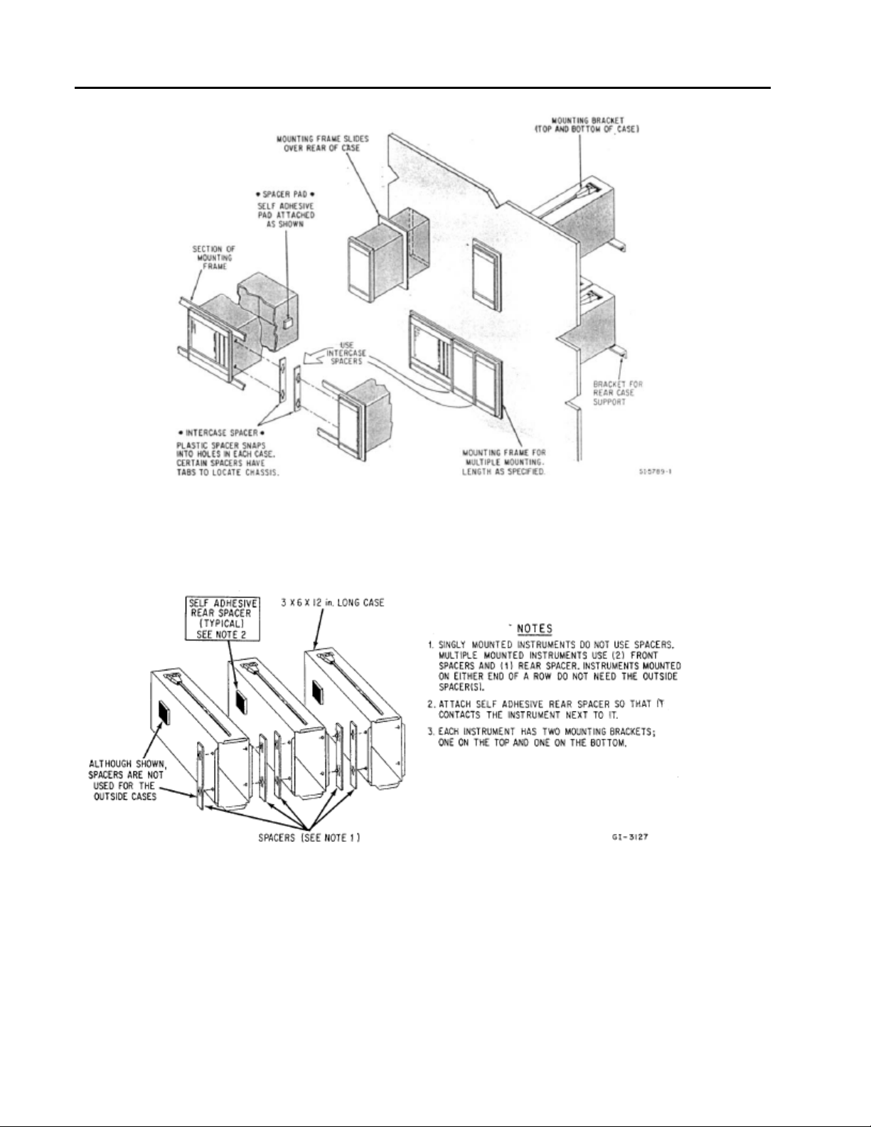
2.3.2 Mounting Procedure
For single and multiple case mounting the instruments are furnished with a trim collar (mounting frame).
Figure 2-2 illustrates the installation and use of the trim collar (mounting frame). Trim collars (mounting
frames) are available in various sizes and are supplied to conform with the particular panel cut-out.
NOTE: Mounting brackets and trim collars (mounting frames) are packaged separately. Check the
shipment carefully to prevent loss of mounting hardware.
To install single or multiple mounted instruments in a prepared panel cut-out, proceed as follows:
1. Remove the through-case shipping bolt.
2. Slip the trim collar (mounting frame) over the rear of the case and slide it forward to the front of the
case.
3. Slide the instrument case through the panel opening.
a. Single mounting case - support the weight of the case and attach the top and bottom
mounting brackets. Tighten the bracket screws.
b. Multiple mounted cases - spacer bars and self-adhesive pads must be used between the
cases, as shown in Figure 2-3. Start the installation from the right (when facing the panel),
installing the spacers as each case is added. Also, as each case is positioned in place, install
and tighten the top and bottom mounting brackets. Each case must be tight against the
previous case.
NOTE: Spacers are not required on the outside of the right and left cases.
6
Page 13

53SL5100B Single-Loop Controller
INSTRUCTION MANUAL
NOTES:
1. DIMENSIONS ARE IN INCHES. DIMENSIONS IN BRACKETS (
) ARE IN MILLIMIETERS.
2. DIMENSIONS GUARANTEED ON CERTIFIED PRINTS ONLY.
3. CASE MOUNTING HARDWARE SUPPLIED UNLESS
OTHERWISE SPECIFIED.
4. THIS DRAWING IS THIRD-ANGLE PROJECTION AS SHOWN
5. UNLESS OTHERWISE INDICATED ALL TOLERANCES ARE ±
1/16 (1.6)
Figure 2.1 Outline Dimensions & Panel Cut-out Requirements
7
Page 14
53SL5100B Single-Loop Controller
INSTRUCTION MANUAL
Figure 2-2. Single or Multiple Panel Mounting
Figure 2-3. Intercase Spacing
8
Page 15

53SL5100B Single-Loop Controller
INSTRUCTION MANUAL
2.4 Power & Signal Wiring
PREPARATORY: The 53SL5100 can be configured for one to four analog inputs (ANI0-3), one analog output
(ANO0), two control contact inputs (CCI0 and 1), two control contact outputs (CCO0 and 1) and Datalink
network interconnectivity. Therefore, prior to making electrical connections, the particular instrument
configuration should be determined with all assigned inputs and outputs identified to assure proper signal
routing.
Provisions for electrical interconnections are located at the rear of the instrument case. Under ideal conditions
shielded cable may not be required. In noisy locations all system input, output and power wiring should be
enclosed in electrical conduit. System interconnection cables (except for power cables) should be fabricated
from 2-wire shielded signal cable. Signal transmission distance should not exceed the limit specified for the
particular transmitter (refer to applicable technical literature provided for the respective device). Polarity must
be observed when connecting the remote transmitters to the instrument.
The instrument has a vertically mounted terminal strip (TB1) for signal interconnections and a horizontally
mounted terminal strip (TB2) for power wiring. Both terminal strips are located at the rear terminal board of
the instrument case.
SNAP-OUT TERMINAL CONNECTORS
Both terminal strips, TB1 and TB2, have removable plug-in connectors. The upper connector for TB1 has
screw lugs 1 through 12 and the lower connector has screw lugs 13 through 22. All of the screw lugs are on a
single connector for TB2. To remove a signal connector, grasp it securely on both sides with the thumb and
forefinger, rock it gently from top to bottom (not side to side) and pull it straight out. To remove the power
connector, grasp the sides firmly with the thumb and forefinger, rock it gently from side to side and pull
straight out.
NOTE: The screw lugs on the back of the instrument are designed for 12 – 24 AWG wire. It is
important that the wire be stripped to expose 1/2 inch of conductor before installation.
WARNING! Instruments that are powered from an ac line service constitute a potential
electric shock hazard to the user. Make certain that these system ac power lines are
disconnected from the operating branch circuit before attempting electrical interconnections.
9
Page 16
53SL5100B Single-Loop Controller
INSTRUCTION MANUAL
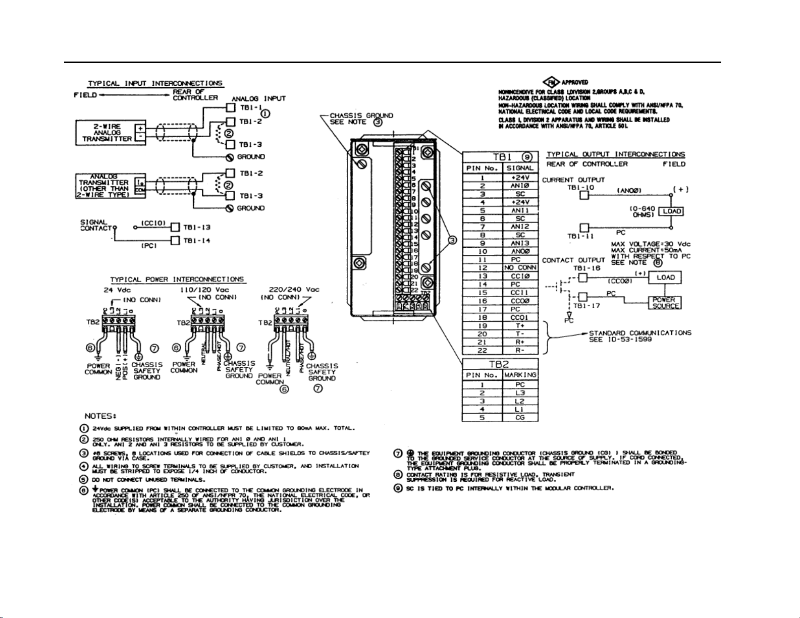
10
Figure 2-4. Controller Rear Power and Signal Terminal Boards
Page 17
53SL5100B Single-Loop Controller
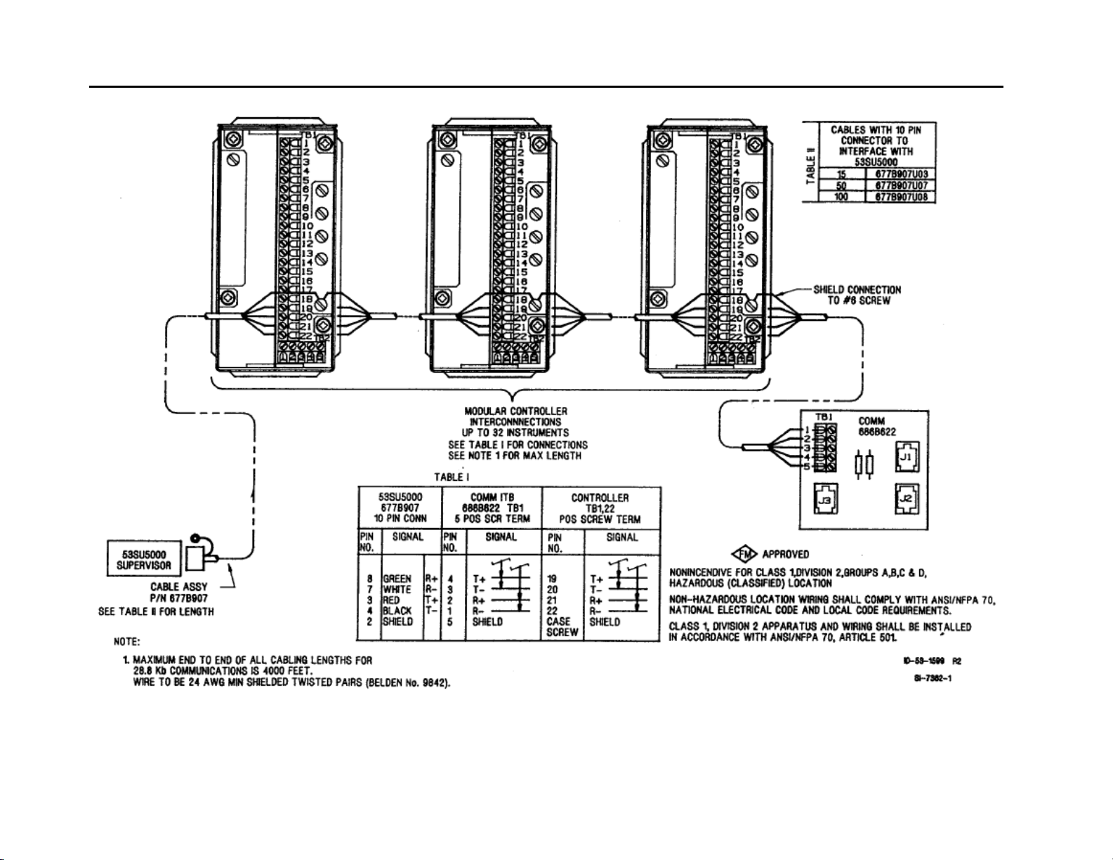
INSTRUCTION MANUAL
Figure 2-5. Datalink Installation Diagram
11
Page 18

53SL5100B Single-Loop Controller
INSTRUCTION MANUAL
2.4.1 Power Wiring
Refer to the instrument model number to verify the power input requirements:
53SL511…. – AC Power
53SL512…. – DC Power
2.4.1.1 DC Power
Reference Figure 2-4 and connect the remote 24 V dc power supply to the instrument as follows:
1.
Connect (+) input line, via remote SPST switch, to terminal L1.
2. Connect (-) input line to the system bus bar. The bus bar should be connected to a good earth ground
(#8 AWG wire is recommended). Individual wires should be run from the controller Power Common
(PC ) and Signal Common (SC ) terminals to the bus bar. The chassis should be grounded by
connecting terminal G to earth ground.
NOTE: Use of a common bus bar is recommended to minimize potential
voltage differences that may occur as the result of ground current loops, e.g.,
potential difference between separate signal grounds, power grounds, etc.
2.4.1.2 AC Power
Reference Figure 2-4 and connect the specified line service (110-120, 220-240 V ac, 50 or 60 Hz) to the
trument as follows:
ins
1. Connect the phase or hot line L, via a remote power disconnect switch or circuit breaker, to terminal
L1.
2. Connect the neutral line N to terminal L2 for 110-120 V ac. Connect the neutral line N to terminal L3
for 220-240 V ac.
3. Connect Power Common to a good earth ground (#12 AWG wire is recommended). The instrument
case should be grounded by connecting terminal G to earth ground at the source of supply
(green/green-yellow ground).
All supply connections include surge protection rated at 275 V ac normal mode.
NOTE: To minimize possible interference, ac power wiring should be routed away from signal
wiring.
2.4.2 Field Signal Wiring
2.4.2.1 Current/Voltage Input to AIN0 and AIN1
When the input signal is from a 4-20 mA current transmitter, a precision 250 ohms (+/-0.1%) resistor is
required. (The resistor tolerance is critical, as the resistor is used to accurately convert the current signal from
the transmitter, which is typically 4-20 mA, to a specified analog input voltage of 1 to 5 V dc). The back of the
rear terminal board has the appropriate resistors (R1 and R2, respectively) for ANI0 and ANI1.
2.4.2.2 Contact Input to CCI0
Separate contact input signals to CCI0 and CCI1 can be used for alarm inputs. One side of each
remote contact must be connected to power common as illustrated in Figure 2-4. Minimum opened
or closed recognition time for a remote contact must be 0.05 seconds.
2.4.2.3 Current Output from ANO0
A current output signal is available for re-transmission of one of the input signals ANI0 through
ANI3. Observe the proper polarity when connecting the output to another instrument.
2.4.2.4 Contact Output CCO0
Discrete contact output CCO0 is identified in Figure 2-4. Each discrete output is a solid state switch with a
rating of 30 V dc, 50 mA maximum. A CCO is referenced to power common. When this contact is connected
to an inductive load, an external arc suppression network is required for contact protection.
12
Page 19

53SL5100B Single-Loop Controller
INSTRUCTION MANUAL
2.4.3 Datalink Communication
Datalink is an interrogator/responder serial interface capable of supporting 32 instruments on a single
network. It uses an RS485 physical interface. The Datalink wiring diagram for this instrument is provided as
Figure 2-5. Complete coverage of the Datalink is provided in Instruction Bulletin 53SU5000.
2.5 Factory Set Calibration
Each unit contains individual factory set entries that calibrate the four analog inputs (ANI0 through ANI3) and
analog output (ANO0). There is a calibration sheet supplied with each instrument that should be retained for
future reference when the installation is completed. Reference Section 5.3 for additional information.
2.6 Grounding
Installations are expected to have access to an independent, high quality, noise-free point of earth reference.
The system should be connected by a dedicated, low resistance (less than one ohm) lead wire directly to the
installation’s point of earth reference. This ground reference is referred to as the Instrumentation Ground. If
an instrumentation ground reference does not exist in the installation, an earth ground electrode should be
established with an independent grounding rod or ground grid mesh.
13
Page 20

53SL5100B Single-Loop Controller
INSTRUCTION MANUAL
14
Page 21
53SL5100B Single-Loop Controller
INSTRUCTION MANUAL
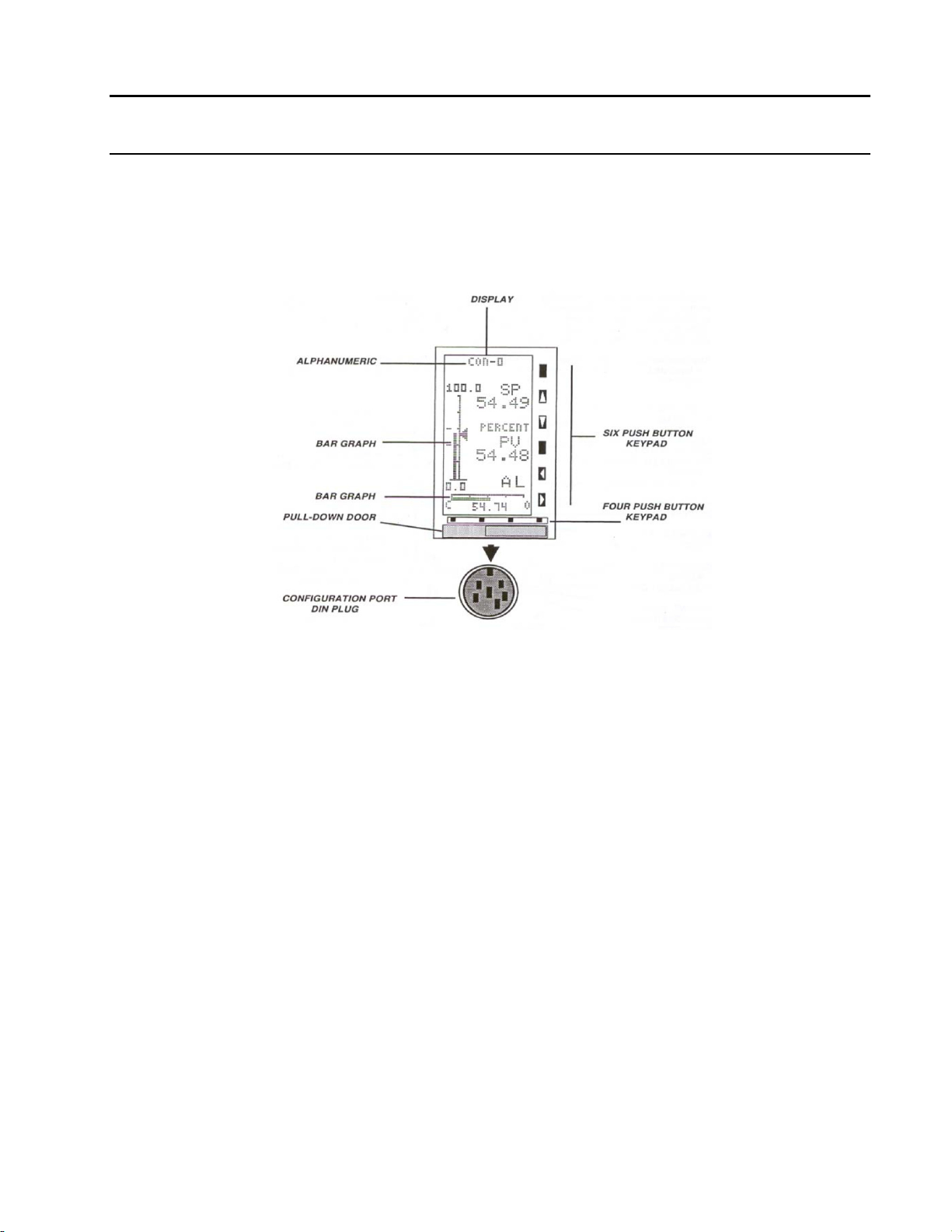
3 FRONT PANEL
The front panel of the instrument contains the display and all push buttons used to change display
presentations and parameters. The front panel has a gas discharge 96 X 48 dot matrix display, a six
pushbutton vertical keypad, and a four pushbutton horizontal keypad. It also has a configuration port DIN
plug, which is concealed behind the identification tag pull-down door. To open this door, press on the lower
front edge. Front panel display information is presented as bar graphs with associated alphanumerics or as
alphanumeric only. (See Figure 3-1.)
Figure 3-1. Front Panel
3.1 Display
The bar graph display is a visual indication of the process events monitored and subsequently altered either
by the instrument or other device. This instrument provides three unique bar graph displays and one
alphanumeric parameter display. Bar graph response dynamics as well as the alphanumerics on all of the
display types are selected when the instrument is configured.
There are four configurable operating modes, called control strategies (CS1-4). The control strategies are:
CS1, Single Loop PID Controller
CS2, Analog Backup Controller
CS3, Ratio Controller
CS4, Automatic/Manual Station
Two of the control strategies, CS1 and CS2, have identical bar graph presentations; that is why there are
three, rather than four, unique bar graph types. Each control strategy (CS1 - CS4) also has a pushbutton
selectable parameter display. Although the contents of the parameter display are selectable configuration
items, the display format is identical for each of the four control strategies.
Any display type can have a portion of its contents overlaid with an ALARM indicator. If the instrument is
manually set to engineering mode, the display can be overlaid with the CONFIGURATION or DISPLAY data
entry line. Alarm indicators warn of variation changes that exceed tolerance limits; the process may require
immediate attention. The engineering mode (EMODE) overlay provides a single entry line for data display and
alteration.
15
Page 22
53SL5100B Single-Loop Controller
INSTRUCTION MANUAL
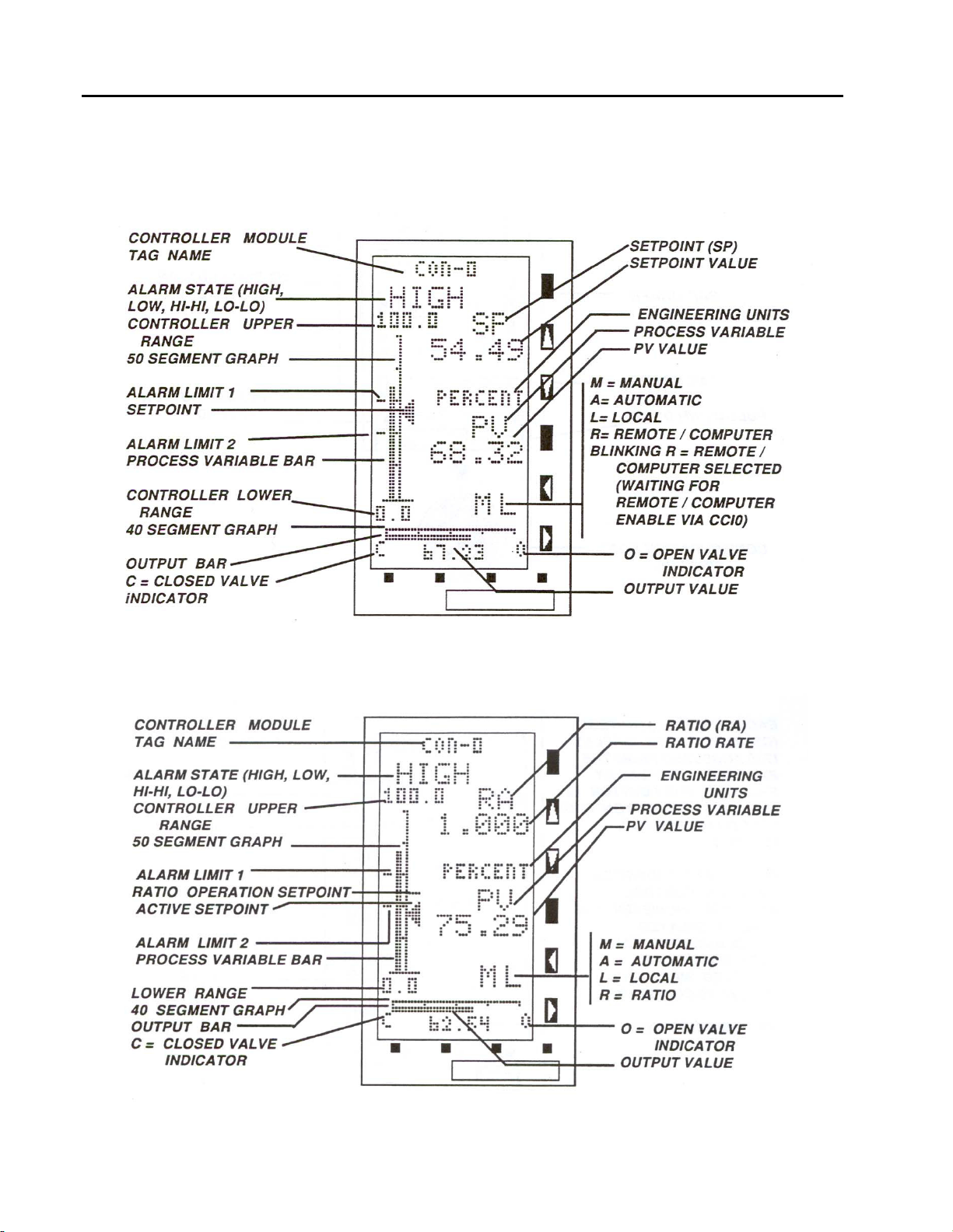
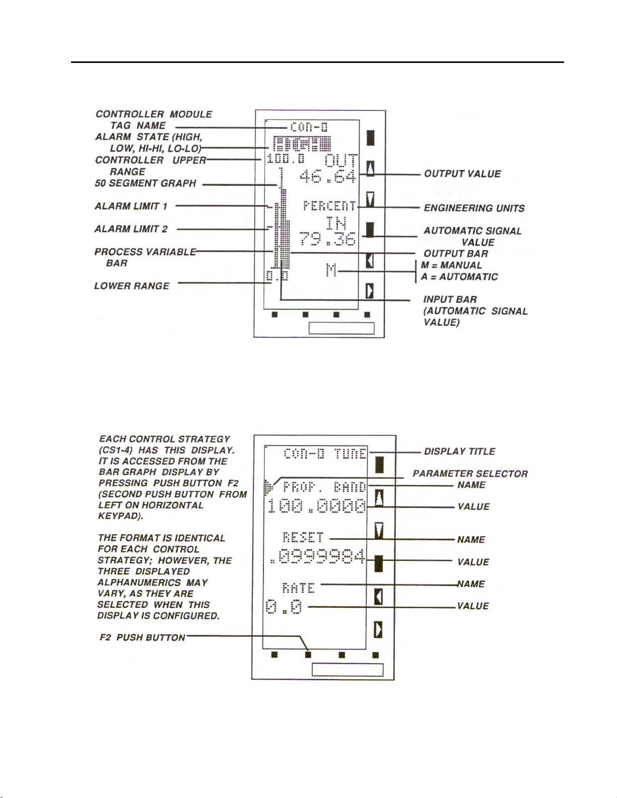
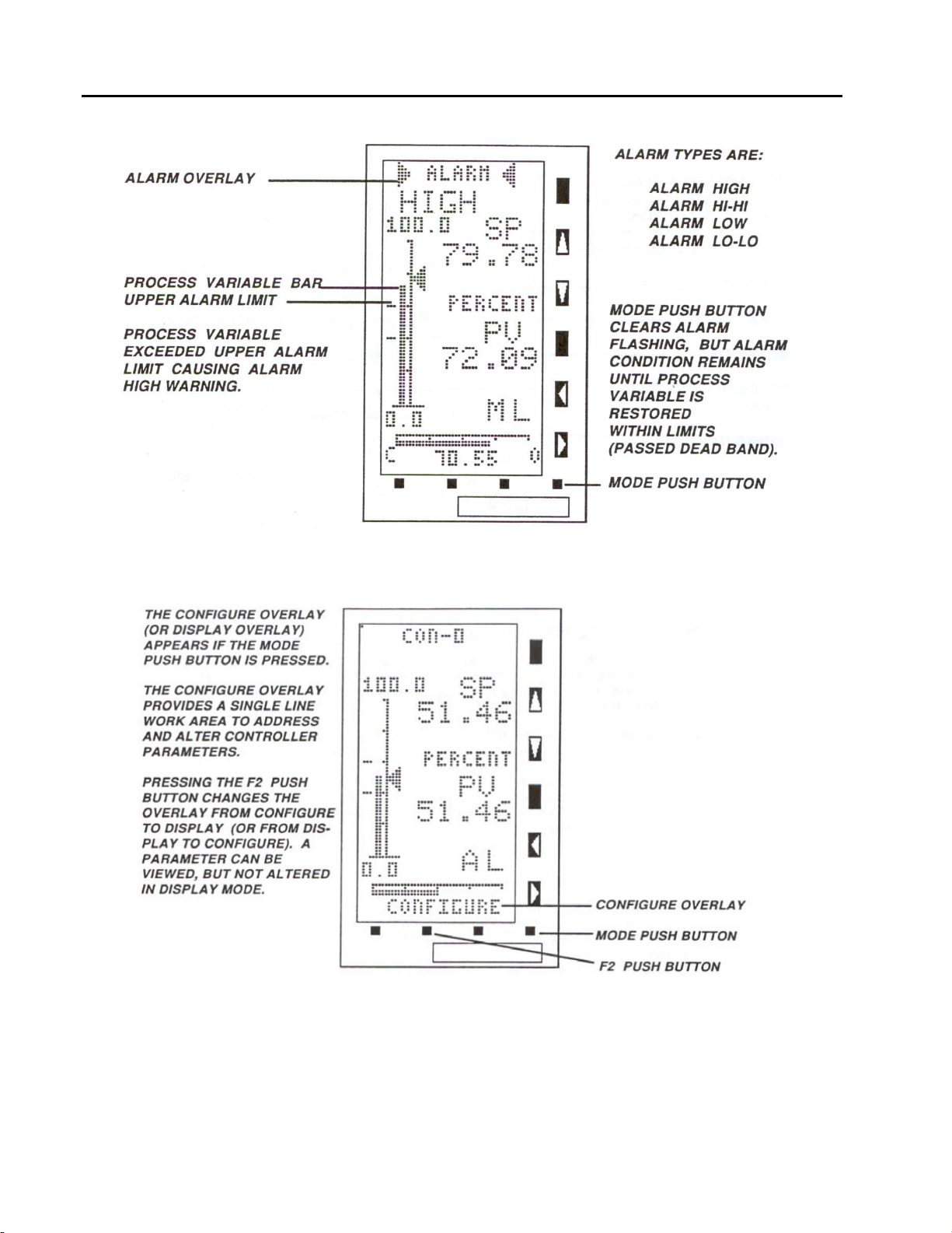
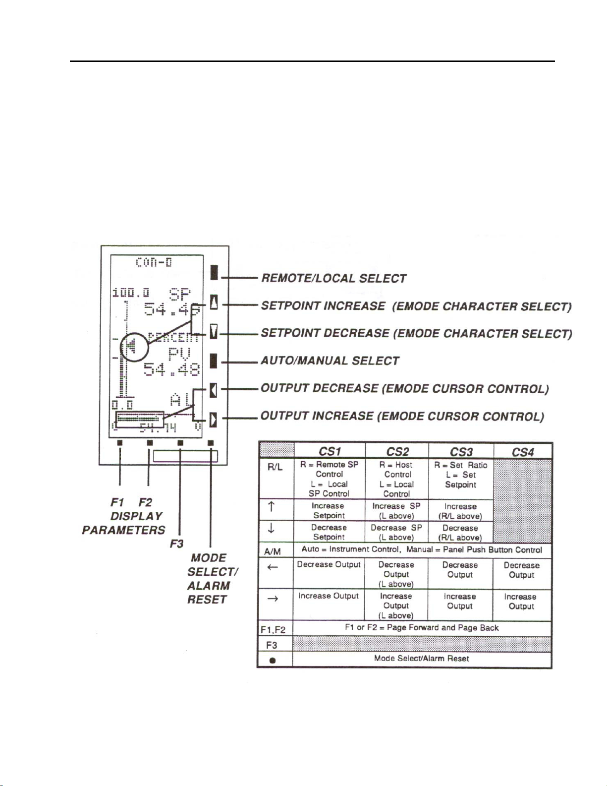
The three bar graph display types for CS1-4 and the parameter display, with appropriate call outs, are
illustrated in Figure 3-2 through Figure 3-5. Figure 3-6 and Figure 3-7 illustrate displays with alarm and
configuration overlays.
Figure 3-2. CS1, Single Loop PID Controller or CS2, Analog Backup Controller
16
Figure 3-3. CS-3, Ratio Controller
Page 23
53SL5100B Single-Loop Controller
INSTRUCTION MANUAL
Figure 3-4. CS4, Automatic/Manual Station
Figure 3-5. CS1 - CS4 Parameter Display
17
Page 24
53SL5100B Single-Loop Controller
INSTRUCTION MANUAL
Figure 3-6. Alarm Overlay
18
Figure 3-7. Configure Overlay
Page 25
53SL5100B Single-Loop Controller
INSTRUCTION MANUAL
3.2 Front Panel Pushbuttons
The front panel pushbuttons are used to vary the display presentation, to select instrument operator or
engineering modes, and to select local or remote setpoint levels. In engineering mode, (EMODE) they are
also used to display and/or alter database parameters which are presented as single line datapoints in the
configuration overlay.
Pushbutton operator mode functions differ slightly with each control strategy implemented; however, the
engineering mode pushbutton functions are identical for all four control strategies. General pushbutton
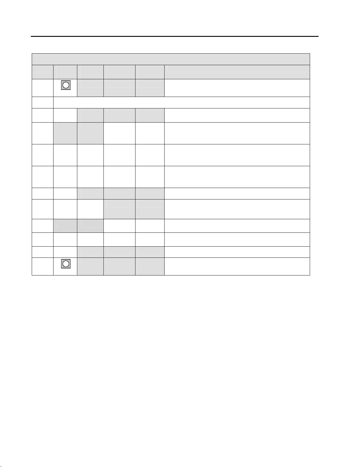
functions are illustrated in Figure 3-8 below and defined in Table 3-1 on the facing page. The summary table
in Figure 3-8 shows the functional differences of the push buttons by control strategy. These differences are
included as part of the push button descriptions provided in each individual control strategy section of the
book.
Figure 3-8. Front Panel Pushbuttons
19
Page 26

53SL5100B Single-Loop Controller
INSTRUCTION MANUAL
Pushbutton Title Operator Mode Engineering Mode
Used to select between Remote setpoint control
and Local setpoint control. When in Remote, an
R appears in the lower right of the display. When
in Local, anLappears in the lower right of the
display.
The setpoint indicator increases (rises) when this
pushbutton is pressed and held. Release the
pushbutton when the desired setpoint level is
reached. This pushbutton is for Local operation
only.
The setpoint indicator decreases (falls) when this
push button is pressed and held. Release the
pushbutton when the desired setpoint level is
reached. This pushbutton is for Local operation
only.
This pushbutton is the Auto/ Manual mode
toggle. When toggled to Auto, an A appears
before the R or L (for Remote or Local), in the
lower middle right of the display. When toggled to
Manual, an M appears before the R or L (for
Remote or Local), in the lower right of the
display. Auto indicates the process is under
instrument control. Manual indicates the process
is controlled by the instrument panel pushbuttons
(e.g., output increase and decrease.
The output indicator decreases when this
pushbutton is pressed and held. Release the
pushbutton when the desired output level is
reached. This pushbutton is for Manual operation
only.
The output indicator increases when this
pushbutton is pressed and held. Release the
push button when the desired output level is
reached. This push button is for Manual
operation only.
These two push buttons have similar functions,
but work in reverse of one another. They are the
bar graph - Param display toggles. The two
display types interchange and alternately appear
each time either one of these two pushbuttons is
pressed.
Not used
This pushbutton clears the flashing ALARM message, but the alarm indication remains until the
process variable is restored within tolerable limits past dead band. It is also used to toggle between
Operator and Engineering modes. If no ALARM message is present, pressing this pushbutton will
toggle the instrument between Operator mode and Engineering mode.
Not used
For configure or a display function, the character
set displays one character at a time in ascending
alphanumeric order when this pushbutton is
pressed and held. Release the push button when
the desired character, number, or symbol
appears.
For configure or a display function, the character
set displays one character at a time in descending
alphanumeric order when this pushbutton is
pressed and held. Release the pushbutton when
the desired character, number, or symbol
appears.
Not used
For configure or display functions, the cursor shifts
one position to the left each time this button is
pressed. When pressed and held, characters
continue to shift left one position at a time.
Maximum character length is 10 characters (9
character shifts).
For configure or display functions, the cursor shifts
one position to the right each time this button is
pressed. When pressed and held, characters
continue to shift right one position at a time.
Maximum character length is 10 characters (9
character shifts).
Pushbutton F2 is used to select the configure or
display functions in EMODE. Pressing F2 in
EMODE alternately selects one function or the
other.
In the configuration function, pressing this
pushbutton causes the addressed datapoint to be
altered with the character string that was entered
with the EMODE Cursor Control and Character
Select pushbuttons. In display function, pressing
this pushbutton causes the addressed datapoint to
display its contents.
F1, F2
F3
Remote/
Local
Select
Setpoint
Increase
(EMODE
Character
Select)
Setpoint
Decrease
(EMODE
Character
Select)
Auto/Manual
Select
Output
Decrease
(EMODE
Cursor
Control)
Output
Increase
(EMODE
Cursor
Control)
Page Forward
and Page
Back
(EMODE
ENTER key)
Mode
Select/Alarm
Reset
20
Page 27
53SL5100B Single-Loop Controller
INSTRUCTION MANUAL
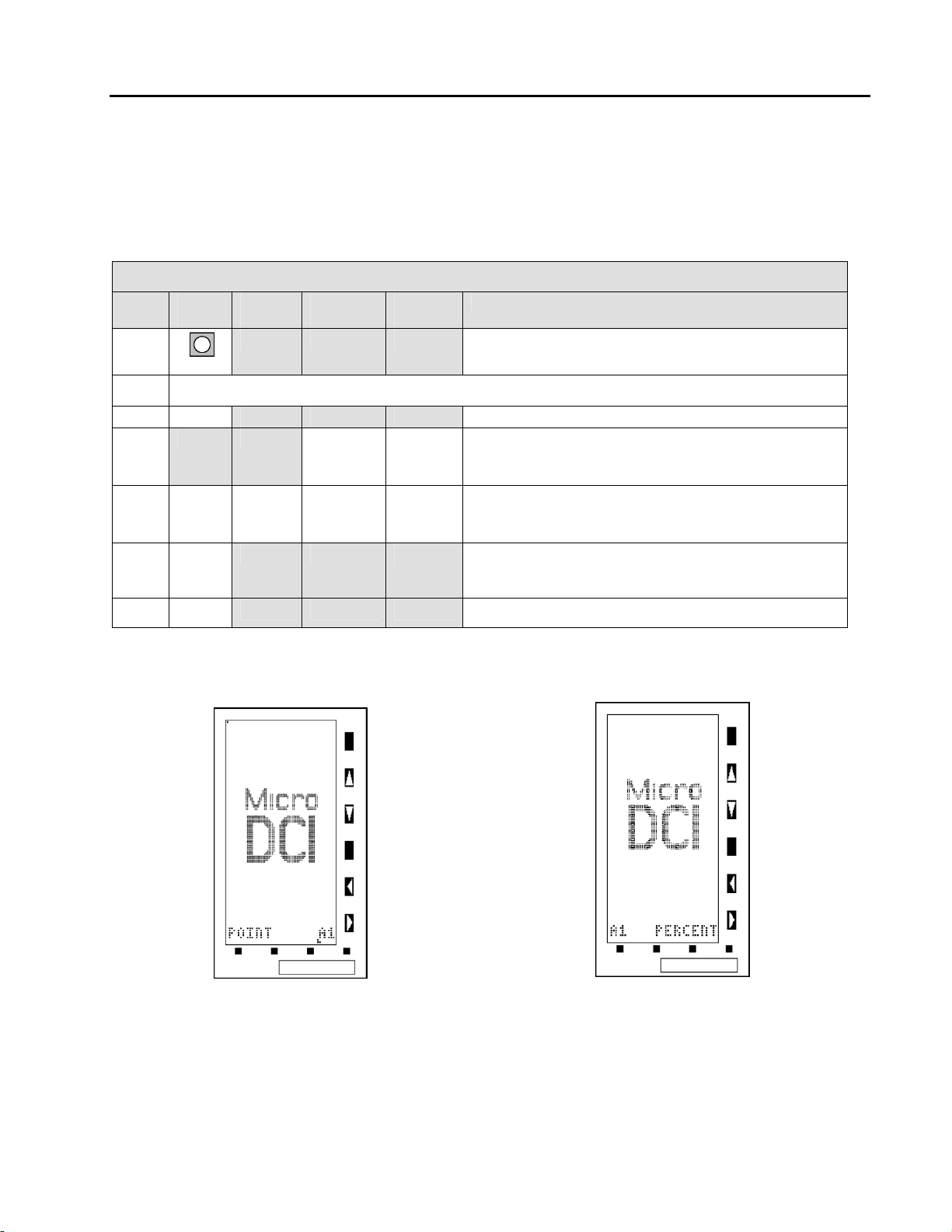
3.3 Displaying a Datapoint
The following procedure illustrates how to enter Engineering Mode (EMODE) and use the display function to
access the contents of datapoint A001 (A1). The displayed contents will be PERCENT. Figure 3-9 and Figure
3-10 are supporting illustrations for the display procedure which is described in Table 3-2. It should be noted
that EMODE has a 20 second timeout if it is accessed and its functions (e.g., configure or display) are not
used.
Table 3-2. Procedures to Display a Datapoint
Step Press
Once
1
MODE
2
3
F3
4
Shift
Result
Press to
Locate
If CONFIGURE appears instead of DISPLAY, press F2.
Target
Char.
A
Result
Puts instrument in engineering mode.
Displays entry line: POINT .
Puts A on entry line: POINT .A.
5
6
7
NOTE:
F3
MODE
Δ = space.
.AΔ
1
Shifts A and puts 1 on entry line: POINT .A1.
Enters address to display datapoint contents.
The address and the contents are displayed as
follows: A1 PERCENT.
Returns instrument to operator mode.
Figure 3-9. POINT.A1 Figure 3-10. A1 PERCENT
21
Page 28
53SL5100B Single-Loop Controller
INSTRUCTION MANUAL
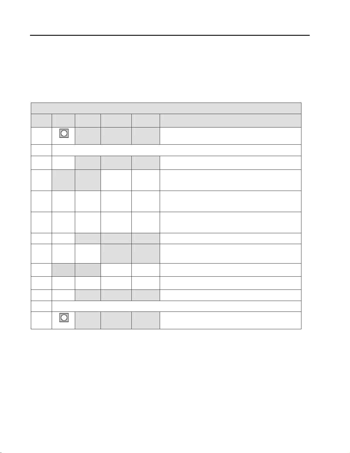
3.4 Altering a Datapoint
The following procedure illustrates how to enter EMODE and use the configuration function to alter the
contents of datapoint B000 (B0) with a 97. Entering a 97 in B00 invokes the display test which strobes the
display matrix dots on and off at 5 second intervals (approximate). When off, a perimeter of dots still remains
lit. Figures 3-11 and 3-12 are display test illustrations that support the procedure provided in Table 3-3. It
should be noted that EMODE has a 20 second timeout if it is accessed and its functions (e.g., configure or
display) are not used.
Table 3-3. Procedures to Display a Datapoint
Step Press
Once
1
MODE
2
3
F3
4
Shift
Result
Press to
Locate
If CONFIGURE appears instead of DISPLAY, press F2.
Target
Char.
B
Result
Puts instrument in engineering mode.
Displays entry line: POINT .
(If the prompt KEY? appears, see Table 3-5.)
Puts B on entry line: POINT .B.
5
6
7
8
9
F3
Hold
.BΔ
0
Shifts B and puts 0 on entry line: POINT .B0.
.B0Δ
0
Shifts B0 and puts 0 on entry line: POINT .B00.
.
locator
9
Displays contents of B00 (0).
B00 contents shifted right; only locator point
remains on the entry line: B00 .
Puts 9 on entry line: B00 .9.
10
11
12
13
NOTE:
22
F3
MODE
Δ = space.
.9Δ
To stop test, change B00 contents from 97 to 00 (Instrument Suspend State).
7
Shifts 9 and puts 7 on entry line: B00 .97.
Enters 97 in B00 to start the display test.
Returns instrument to operator mode.
Page 29
53SL5100B Single-Loop Controller
INSTRUCTION MANUAL
Figure 3-11. Checkerboard Pattern Figure 3-12. Permiter Dots Illuminated
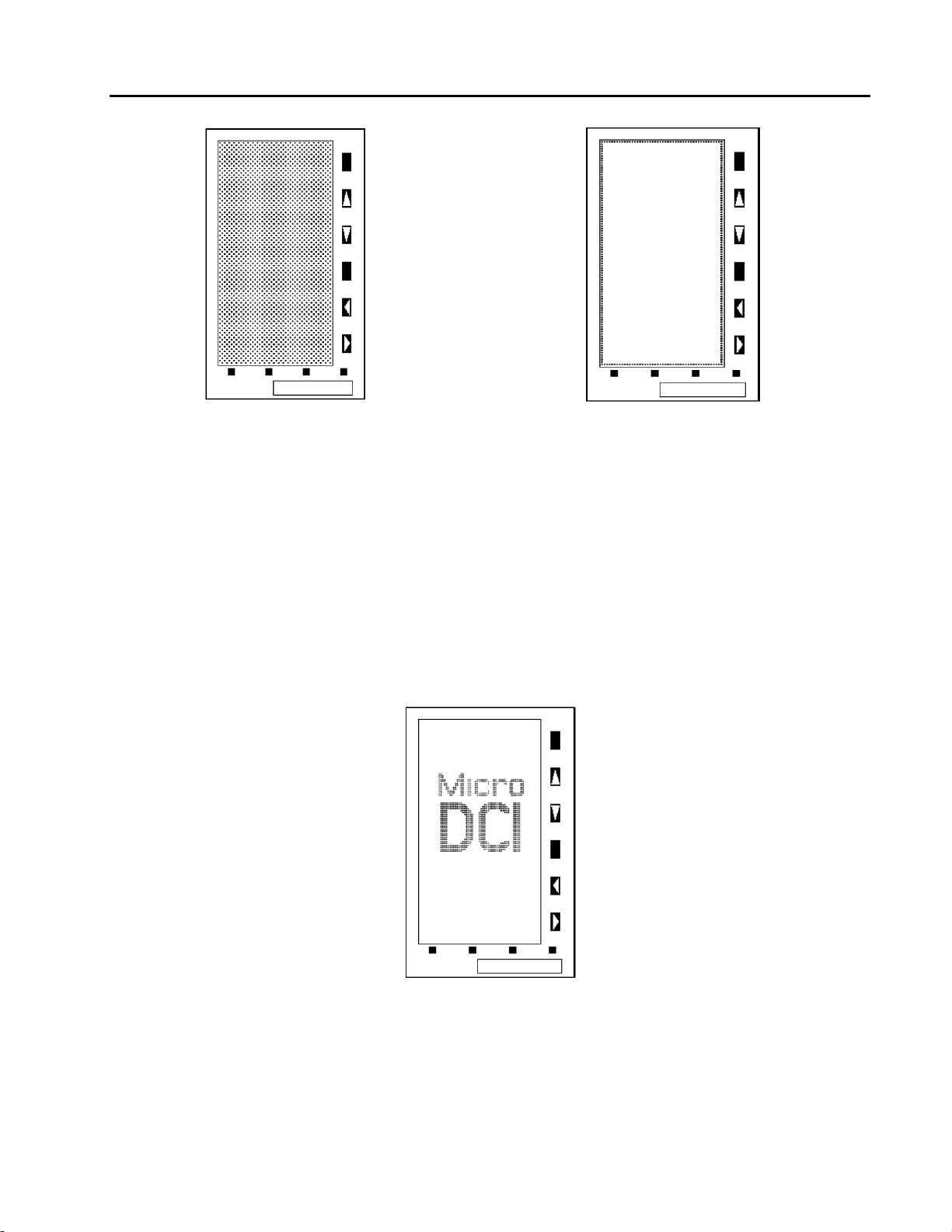
3.5 Defaulting the Database
Defaulting the database sets all non-instrument-specific datapoint parameters to predetermined values, then
suspends the instrument which is indicated by the logo presented on the display. When instrument operation
is suspended, instrument algorithmic control ceases.
The procedure to default the database is presented in Table 3-4 and the display logo is illustrated in Figure 3-
13. Entering a 98 in datapoint B00 defaults the database. If it is desired to suspend instrument operation
without defaulting the database, enter a 00 in lieu of a 98 into B00. The defaulted database values are
provided in the configuration tables of Section 4 and the database tables in Appendix C, Database, under the
column headed Default. Those parameter values that are left unaltered when the database is defaulted are
identified with gray-tone shading in the Default column of the tables. It should be noted that EMODE has a 20
second timeout if it is accessed and its functions (e.g., configure or display) are not used.
Figure 3-13. Display Logo
23
Page 30
53SL5100B Single-Loop Controller
INSTRUCTION MANUAL
Table 3-4. Defaulting the Database
Step Press
Once
1
MODE
2
3
F3
4
Shift
Result
Press to
Locate
If DISPLAY appears instead of CONFIGURE press F2.
Target
Char.
B
5
6
7
8
9
F3
Hold
.BΔ
0
.B0Δ
0
.
locator
9
Result
Puts instrument in engineering mode.
Displays entry line: POINT .
(If the prompt KEY? appears, see Table 3-5.)
Puts B on entry line: POINT .B.
Shifts B and puts 0 on entry line: POINT .B0.
Shifts B0 and puts 0 on entry line: POINT .B00.
Displays contents of B00 (0).
B00 contents shifted right; only locator point
remains on the entry line: B00 .
Puts 9 on entry line: B00 .9.
10
11
12
NOTE:
F3
MODE
Δ = space.
.9Δ
8
Shifts 9 and puts 7 on entry line: B00 .98.
Enters 97 in B00 to default the database.
Returns instrument to operator mode.
24
Page 31

53SL5100B Single-Loop Controller
INSTRUCTION MANUAL
3.6 Responding to the Prompt: KEY?
When the password prompt KEY? appears, it indicates a password was set in the MicroTools software. The
password can not be set via the front panel push buttons.
A password key is a maximum of 10 numeric characters (numbers 0-9 only). It does not impede display
functions in engineering mode but must be unlocked to perform configuration functions. A password key is
NOT SET FOR NEW INSTRUMENTS from the factory; therefore, if it is set, it must have been done locally.
The password must first be obtained from the originator before the procedure in Table 3-1 can be used to
access the engineering mode configuration function capabilities.
Table 3-5. Entering a Key Password
Step Press
Once
1
Shift
Result
Press to
Locate
Target
Char.
Result
Puts instrument in engineering mode.
2
3
F3
4
If DISPLAY appears instead of CONFIGURE, press F2.
Displays password query: KEY?
2
Puts first password number on entry line: KEY? .N.
5
.2Δ
6
7 Repeat step 6 until all of the password characters are entered.
.22Δ
2
2
8
F3
NOTE: Δ indicates Space. N = any numeric value 0-9.
Shifts 2 and puts second password number on entry
line: KEY? .NN.
Shifts 22 and puts third password number on entry
line: KEY? .NNN.
Enters the password key and displays the entry line:
POINT . The engineering mode configuration
function is now accessible for use.
25
Page 32

53SL5100B Single-Loop Controller
INSTRUCTION MANUAL
26
Page 33

53SL5100B Single-Loop Controller
INSTRUCTION MANUAL
4 CONFIGURATION PARAMETERS
The configuration parameters provide the latitude to define the instrument’s personality attributes, so that
while still functioning within its designed specifications, it can perform application requirements with greater
refinement. Typical configuration parameters are the instrument’s indicator zero point and span, the display
tag names, engineering units of the displayed process value, and alarm limits, etc. IT IS NOT NECESSARY
TO DEFINE ALL OF THE CONFIGURATION PARAMETERS, as commonly used preset values may not have
to be altered and certain parameter selections eliminate others.
Although all resident in a memory database as datapoints, the configuration parameters are clustered into
modular groups that may have specific hardware identities (e.g., the ANI, ANO, CCI, and CCO circuits
illustrated in Figures 4-1 through 4-4), or may represent software controlled functions that are not specific to
any one hardware element.
4.1 Datapoint Types
A parameter can be any one of five data types. Each data type represents a specific data format:
integers, alphanumeric text strings, etc. A database module containing multiple parameters can
have a mix of data types. The data types are defined in Table 4-1 as follows:
Table 4-1. Datapoint Types
Type Byte
Size
L 1 Bit Represents a single binary bit that can have the value of 0 or 1.
B 1 Represents a positive integer with values from 0 to 255.
C 3 Represents a real analog (floating point) value that has a resolution of one part in 32,768 (15 bits)
H 5 Represents a high precision analog (floating point) value that has a resolution of one part in 2
A 10 Represents a text string that can be 10 characters long.
F 5 Represents text strings that can be 5 characters long.
4.2 Factory Standard Calibration
The instrument is shipped from the factory configured as summarized in Table 4-2.
Table 4-2. Factory Standard Calibration
Datapoint Value Attribute
B000 1
C106 100
C107 0
C108 0
B335 1
C256 100
L416 0
L106 1
L115 0
Displays
2. Parameter 1 Display
Format
and a dynamic range of ± 10
billion (31 bits) and a dynamic range of ± 10
This value indicates Single Loop PID Controller operation.
Proportional Band = 100%.
No Reset (TR) action.
No Derivative (TD) action.
No Alarms.
ANI0 Engineering Span Input (Process Variable [PV] Input) = 0% - 100%.
ANI0 Input Voltage Range is 1 -5 V.
Reverse Switch is set so that the instrument output decreases as PV increases.
Remote Setpoint Disabled indicates the setpoint value established in Local mode
remains in effect when the instrument is placed in Remote mode.
1. As configured: Display of Single Loop Controller, Analog Back-up Controller,
Ratio Controller, or Automatic Manual Station
38 .
38 .
27
Page 34

53SL5100B Single-Loop Controller
INSTRUCTION MANUAL
If the state of the database is unknown, the instrument can be returned to the factory standard configuration
with two datapoint entries:
1. Set B00 to 98 to default the database.
2. Set B00 to 1 to start functioning as a Single Loop Controller.
If the unit is to be operated online, it must be installed as described in Section 2, Installation. ANI0 (PV Input)
and ANO0 (Output) must be connected, and the unit must have power applied.
4.3 Configuring the Database Modules
The datapoints in the database modules must be changed to reflect required alterations in the factory
standard configuration or when the instrument is re-configured. There are generally four datapoint parameter
types contained in the eight database modules. The parameter types affect Datalink communications, display
indications, input-output signals, and alarm conditions. The eight database modules are described in Table 4-
2. Although it is not an absolute criterion, it is assumed the modules will be configured in the table Item order;
however, if the instrument is to be connected to a Datalink network, item 7, Communication Module, should
be configured first. By configuring the Communication Module first, the instrument can function on the
Datalink and the remaining datapoint values can be entered via the Datalink interrogator (master). Reference
the applicable instruction bulletin IB 53SU5000 for the procedure.
Table 4-2 is also a pointer to the descriptions of the database modules; the descriptions are presented
as Tables 4-3 through 4-10. (The gray tone shading in the default cell of a datapoint indicates the datapoint
contents are left unchanged after default. See Section 5.5 for the default procedure.)
Table 4-3. Database Modules
Item Title Purpose See
Table
1 Analog Input Module This module is used to configure the voltage input
characteristics (e.g., input voltage range) and how the input
signal is interpreted (linear or square root representation).
2
Analog Output Module
3 Contact Input Module This module allows the action of the CCIs to be reversed
4 Contact Output
Module
5 Controller
Module
6 Parameter
Display Module
7 Communication
Module
8 System Module This module is used to set the instrument tag name and the
The primary purpose of this module is to set the 0 - 20 mA
output signal relative to the displayed percent output.
(normally a closed contact = 1, but can be change to = 0).
This module allows the action of a CCOs to be reversed
(normally a closed contact = 1, but can be changed to = 0).
The primary purpose of this module is to set the instrument’s
responsiveness, Alarm Limits t & 2, Alarm Dead Band, and
the range limits (e.g., 0 - 100, -20 - 80, etc.).
This module provides quick pushbutton display access to
any
three selected datapoints for viewing or modifying (e.g.,
Alarm Limits 1 & 2 and Alarm Dead Band) without the
necessity of entering Engineering mode and addressing the
datapoints.
This module is used to configure the Datalink port
parameters (e.g., baud rate, parity selection, etc.).
display brightness.
4-10
4-11
4-4
4-5
4-6
4-7
4-8
4-9
28
Page 35

53SL5100B Single-Loop Controller
INSTRUCTION MANUAL
Table 4-4. Analog Input (ANI) Module
Purpose: This module is used to configure input voltage characteristics (e.g., input voltage range), and how the
input signals are interpreted (linear or square root representation).
Title Symbol
Analog
Input
(Display
Only)
ANI H000 H001 0
ANI0
Datapi
nt
ANI1
Datapoint
Default Attributes
This is the value in engineering units of the
measured input after all signal conditioning has
been applied.
Engineering
Span
Engineering
Zero
Digital Filter
Index
0 - 5 V Input NOBIAS L416 L417 0
Square Root
Signal
Calibrate
Zero
Calibrate
Span
SPAN C256 C257 100
ZERO
DFILT B269 B270 3
SQRT L440 L441 0
CIZ B263 B264
CIS C296 C297
C276
C277 0 This is the lower range value.
This determines the upper range the analog
input represents in engineering units. The
upper range value equals Engineering Zero
plus Engineering Span.
This controls a first order filter that is applied
to the input signal. The time constant is
entered as an index value as follows:
0 -No Smoothing (no effect)
1 -0.05 s
2 - 0.1 s
3 - 0.3 s
4 - 0.7 s
5 - 1.5 s
Setting this parameter to 1 indicates the input
range is from 0 -5 volts (0 -20 mA). 0
indicates the input range is from 1 -5 volts (4 20 mA).
When a 0, it indicates the analog input signal
should be interpreted linearly.
When 1, it indicates the analog input signal
should be interpreted as a square root
representation of the value. When square root is
selected, input signals less than 1% (10% input
range) forces the input to its zero value.
This is the calibration zero adjustment. This
parameter is factory set and should not need
adjustment under normal operation.
See Section 5.3 for adjustment.
This is the calibration span adjustment. This
parameter is factory set and should not
need adjustment under normal operation.
See Section 5.3 for adjustment.
6 - 3.1 s
7 - 6.3 s
8 -12.7 s
9 -25.5 s
10 -51.1 s
11 - 102 s
12 - 205 s
13 - 410 s
14 - 819 s
15 -1638 s
Tag Name AITAG A224 A225
Engineering
Units
AIEU A298 A299
ANI-0
ANI-1
PERCENT
(ALL)
An assignable 10 character name for the analog
input (ANI-0, ANI-1, ANI-2, ANI-3).
Assignable for units of measure the ANI
represents (e.g., GPM for gallons/minute).
29
Page 36

53SL5100B Single-Loop Controller
INSTRUCTION MANUAL
Figure 4-1. ANI0-3 Figure 4-2. ANO0
NOTE: These figures are graphical representations of the signal conditioning that occurs on the
instrument main board. They are provided for reference purposes only.
Table 4-5. Analog Output (ANO) Module
Purpose: The primary purpose of this module is to set the 0 - 20 mA output signal relative to the
displayed percent and to select the analog input signal (ANI0-3) that is to be routed to the analog
output (ANO0).
Title Symbol ANO0
Datapoint
Analog Output
(Display Only)
0 -20 mA
Output
Calibrate Zero COZ0 B267
Calibrate
Span
Tag Name AOTAG0 A244 ANO0 The assignable 10 character name for ANO0.
ANO0 C000 0 The value in this datapoint represents the
OZBASE0 L472 0
COS0 C300
Default Attribute
percent of output to be generated by hardware
(e.g., 100% output = 20 mA).
When a 0, the percentage output generates a 4
-20 mA signal. When set to 1 , the percentage
output generates a 0 -20 mA signal.
These parameters are factory set and should
not need adjustment under normal operation.
See Section 5.3 for adjustment.
Table 4-6. Contact Input Module (CCI)
Purpose: This module allows the action of the CCI to be reversed (normally a closed contact = 1, but can be
changed to = 0).
Datapoint
Title Symbol
Contact
Input
(Display
Only)
Contact
Input
Invert
Tag
Name
30
CCI0 L000 0
IINV0 L264 0 0 As shown above, it reverses the action of the CCI datapoint.
CITAG A262 CCI0 It is an assignable 10 character name for the contact control input.
Default Attribute
When open, a 4 -24 V dc input signal = 0 when IINV = 0.
When open, a 4 -24 V dc input signal = 1 when IINV = 1.
When closed, a < 1 V dc input signal = 1 when IINV = 0.
When closed, a < 1 V dc input signal = 0 when IINV = 1.
Page 37

53SL5100B Single-Loop Controller
INSTRUCTION MANUAL
Table 4-7. Contact Output Module (CCO)
Purpose: This module allows the action of the CCO to be reversed (normally a closed contact = 1, but can be
changed to = 0).
Title Symbol Data-point Default Attribute
Contact
Output
(Display
Only)
Contact
Output
Invert
Tag
Name
CCO L024 0
OINV L288 0
COTAG0
COTAG1
A280
A281
CCO-0
CCO-1
If CCO = 0 and OINV = 0, then it is open.
If CCO = 0 and OINV = 1, then it is closed.
If CCO = 1 and OINV = 0, then it is closed.
If CCO = 1 and OINV = 1, then it is open.
As shown above, it reverses the action of the
CCO datapoint.
An assignable 10 character name for the
contact control output.
Figure 4-3. CCI0 Figure 4-4. CCO0
NOTES:
WD = Watchdog
These figures are graphical representations of the signal conditioning that occurs on the
instrument main board. They are provided for reference purposes only.
31
Page 38

53SL5100B Single-Loop Controller
INSTRUCTION MANUAL
Table 4-8. Control Module
Purpose: The primary purpose of this module is to set the instrument’s responsiveness, Alarm Limits 1 &
2, Alarm Dead Band, and the range limits (e.g., 0 - 100, -20 - 80, etc.).
Note:
Title Symbol
Control Alarm
Mode
B335 PV PL1
0 >60 60 HIGH Alarm Llimit 1 is set for 60: PV > 60 = HIGH alarm
0 <40 40 LOW Alarm Limit 2 is set for 40: PV < 40 = LOW alarm
2 >60 60 HIGH Alarm Limit 1 is set for 60: PV > 60 = HIGH alarm
2 <40 40 N/A Alarm Limit 2 is set for 40: PV < 40 = no alarm
3 >60 60 N/A Alarm Limit 1 is set for 60: PV > 60 = no alarm
3 <40 40 LOW Low Alarm Limit 2 is set for 40: PV < 40 = LOW alarm
4 >60 60 HIGH Alarm Limit 1 is set for 60: PV > 60 = HIGH alarm
4 <70 70 HI- HI Alarm Limit 2 is set for 70: PV > 70 = HI-HI alarm
5 >40 40 LOW Alarm Limit 1 is set for 40: PV < 40 = LOW alarm
5 <30 30 LO-LO Alarm Limit 2 is set for 30: PV < 30 = LO-LO alarm
6 >50 10
6 <30 -10
■= applicable to the Control Strategy (CS) as shown in column three.
AIX
(C103)
CS
■
1 | 2 | 3 | 4
■
PL2
(C104)
Alarm Setpoint Notes
DEV
LO-
DEV
CON-0
Datapoint
B335 1
Alarm Examples:
HI-
40 Alarm Limit 1 is set for 40: PV < 40 = HI-DEV alarm
40 Alarm Limit 2 is set for 30: PV < 30 = LO-DEV alarm
Default Attribute
This parameter defines the Alarm Active (PA1
& PA2) interpretation of the two Alarm Limits
(PL1 & PL2). It is entered into the datapoint as
an index value (0-6 ) as follows:
0 PA1n: high when PV> PL1
PA2n: low when PV< PL2
1 None
2 PA1n: high when PV> PL1
PA2n: not affected
3 PA1n: not affected
PA2n: low when PV< PL1
4 PA1n: high when PV> PL1
PA2n: hi-hi when PV> PL2
5 PA1n: low when PV< PL1
PA2n: lo-lo when PV< PL2
6 PA1: Hi-Dev when Dev > PL1
PA2: Lo-Dev when Dev < PL2
32
Page 39

53SL5100B Single-Loop Controller
INSTRUCTION MANUAL
Table 4-8. Control Module (continued)
Purpose: The primary purpose of this module is to set the instrument’s Alarm Index mode, Alarm
Limits 1 & 2, and Alarm Dead Band.
CS
Title Symbol
■
1 | 2 | 3 | 4
Control Action RSW
Reverse Valve RSV
Manual
Fallback
Disable
Alarm Limit 1 PL1
Alarm Limit 2 PL2
Alarm
Dead
Band
Proportional
Band
Reset Time TR
Rate Time TD
Manual Reset MR
Controller
Span
Controller
Lower Range
Control Tag
Name
Engineering
Units
MFD
ADB
PB
■
■
■
■
■
■
■
■
■
■
■
■
■
■
NOTE: CS1 = Single Loop (PID) Controller, CS2 = Analog Backup Controller, CS3 = Ratio
Controller, and CS4 = Automatic/Manual Station.
CON-0
Datapoint
106 0
L109 0
L120 0
C103 100
C104 0
C105 2
C106 100
C107 0
C108 0
C111 50
C115 1100
C116 0
A000
A001 Percent The default is PERCENT, but is assignable as units
Default Attribute
When set to a 0, the controller output increases as
the process value increases.
When set to a 1, the controller output decreases as
the process value increases.
This parameter provides information for the control
display to indicate which direction the control output
must go to close the final control element. A 1
indicates that 20 mA closes the valve. A 0 indicates
that 20 mA opens the valve.
Under normal operation, whenever the controller is
powered up, the Auto/Manual Selector is forced to
the Manual position. When this datapoint is set to a
1, the selector will not be forced to the Manual
position at power up but will remain in the last
position before power was removed.
These parameters are the points in engineering
units at which the alarms are triggered.
This parameter sets the activation/deactivation gap
for the alarm. This value in engineering units
defines an area of hysteresis at the alarm point.
This parameter is the percent of error required to
move the output full scale for proportional action. It
modifies the controller response in standard PID
terms.
This parameter represents the number of minutes
per repeat of integral action. It modifies the
controller response in standard PID terms.
This parameter value represents the minutes that
proportional action is advanced (derivative action).
This parameter determines the position of the valve
(output) when the instrument is in Automatic mode
and the error is zero. (It is only in effect when TR =
0.)
These two parameters set the upper and lower
values on the controller display. They permit the
control action to be defined over a range
independent of the process variable input range.
They also determine the speed at which the
setpoint changes when the up or down arrow
pushbuttons are pressed (CS1 through CS3). For
CS4, they determine only the displayable range, as
the setpoint pushbuttons are not used.
An assignable 10 character name that appears with
CS1-4 displays.
of measure the Process Variable represents.
33
Page 40

53SL5100B Single-Loop Controller
INSTRUCTION MANUAL
Table 4-9. Parameter Display Module
Purpose: This module provides quick pushbutton display access to any three selected datapoints (e.g.,
Alarm Limits 1 & 2 and Alarm Dead Band) without the necessity of entering Engineering mode and
addressing the datapoints.
Title Symbol PAR1 Default Attribute
Title
Point 1 Name
Point 2 Name
Point 3 Name
Point 1 Designator
Point 2 Designator
Point 3
Modify Disable
PTAG A014
PNA A015
PNB A016 RESET
PNC A017 RATE
PDA F087
PDB F088
PDC F089 C108
PMD L313 0
CON-0
TUNE
PROP.
BAND
C106
value
C107
value
This is an assignable in character name that appears
with the parameter display.
This is an assignable 10 character name for the Point
1 Designator.
This is an assignable 10 character name for the Point
2 Designator.
An assignable 10 character name for the Point 3
Designator
A database datapoint whose contents will be
displayed under the Point 1 Name (e.g., C103 to
display the Alarm Limit 1 setting).
A database datapoint whose contents will be
displayed under the Point 2 Name (e.g., C104 to
display the Alarm Limit 2 setting).
A database datapoint whose contents will be
displayed under the Point 3 Name (e.g., C105 to
display the Alarm Dead Band).
When this value is 1, the datapoints in this module can
not be altered with the pushbuttons. The values of
these datapoints are only for display purposes. When
this value is 0, the datapoints in this module can be
altered by the operator with the pushbuttons when this
module is displayed.
34
Page 41

53SL5100B Single-Loop Controller
INSTRUCTION MANUAL
Table 4-10. Communication Module
Purpose: This module is used to configure the Datalink port parameters (e.g., baud rate, parity selection,
etc.).
Title Symbol Datapoint Default Attribute
It identifies the address of this instrument on the
Instrument
Address
Baud Rate BR B02 253
No Parity CP L2561 0
No Byte
Stuffing
Datalink
Disable
IA B01 0
CB L2581 0
DLD L257 0
Datalink network. Each unit connected to the Datalink
network must have its own unique address. Valid
addresses are from 0 -31.
This datapoint value designates the baud rate (data
transfer rate) of the Datalink network. The baud rate
must be the same for all of the instruments connected to
the same Datalink network. Datapoint values and their
corresponding baud rates are as follows:
Value Baud Rate Value Baud Rate
255 28800 9 28800
254 14400 8 14400
N/A N/A 7 19200
253 9600 6 9600
250 4800 5 4800
244 2400 4 2400
232 1200 3 1200
208 600 2 600
160 300 1 300
N/A N/A 0 110
This datapoint indicates if parity generation and
checking should be turned on or off. It is set to 0 for
even parity serial byte protocol. It is set to 1 for no parity
protocol.
When set to a 1, this datapoint disables the standard
communication protocol feature which inserts a 00
(NUL) byte after every 7EH (SOH) that is not the
beginning of a message. (This permits user written
communications software to determine the number of
bytes to expect in a response message.) It must be set
to 0 when using the Micro-DCI communications
software or equipment.
When set to 0 , it permits full Datalink communication
capabilities. When set to 1, it disables Datalink
communication capabilities.
35
Page 42

53SL5100B Single-Loop Controller
INSTRUCTION MANUAL
Table 4-11. System Module
Purpose: This module is used to set the instrument tag name and the display brightness.
System
Title Symbol
Function Index FIX B00 0
Display
Brightness
Index
EASY-TUNE
Enable
BRIGHT B012 4
ETE B08 0
Module
Datapoint
Default Attribute
The operational algorithm of the unit is selected
by the value of this parameter:
0 = Suspend mode. No control algorithm
execution. The logo is displayed.
1 = CS1, Single Loop PID Controller operation
2 = CS2, Analog Backup Controller operation.
3 = CS3, Ratio Controller operation.
4 = CS4, Automatic/Manual Station operation.
97 = Display Test. The entire display alternately
flashes on and off. When off, a border around
the display perimeter remains lit.
98 = Defaults database then sets FIX to 0.
This parameter controls the display screen
intensity. A value of 0 is the brightest and a
value of 7 is the dimmest intensity. Normal
viewing setting is 4.
When set to a 1, the EASY-TUNE algorithm is
implemented. This parameter is left at 0 for
normal instrument operation. (See Section 11 for
Unit Tag Name TAG A08 SL5100
EASY-TUNE.)
An assignable 10 character name for the system
module (SL5100).
36
Page 43

53SL5100B Single-Loop Controller
INSTRUCTION MANUAL
5 SINGLE LOOP (PID) CONTROLLER
5.1 Operation Overview
In a standard feedback control loop, the Single Loop (PID) Controller functions as the primary processing unit.
When the process is altered due to disturbances (e.g., flow rate changes), the controller gauges this change
from the process variable (PV) feedback signal sent to it by a process measurement instrument (e.g., flow
meter) in the loop.
The controller compares the feedback signal to the setpoint level and calculates the required error correction,
which is applied as an output signal to the final control element (e.g., valve) in the loop. The final control
element responds to alter the process (manipulated variable) toward a predetermined operational setpoint
(SP), which can be set locally at the controller front panel or remotely from another instrument. If the process
variable exceeds tolerable limits of change, the controller activates a signal to an alarm. These events are
illustrated in Figure 5-1.
Figure 5-1. Standard Feedback Control Loop
Process variable feedback input (Analog Input) received from the process measurement instrument is
typically 1-5 V dc, 4-20 mA dc. The Single Loop Controller zero and span inputs for this signal are calibrated
by the factory and should not be altered. The controller is defaulted to display the process variable input as a
percentage value determined by input signal amplitude; however, it can be configured to display direct units
of measurement (e.g., gallons per minute [GPM]).
The setpoint value is received from another device (e.g. Single Loop Controller, PC, host computer, etc.), or
is manually entered at the controller front panel.
NOTE: To minimize sudden process changes, adjust the local setpoint value to the
original remote setpoint value before switching back to remote setpoint control
(Remote).
37
Page 44

53SL5100B Single-Loop Controller
INSTRUCTION MANUAL
It is the difference between the setpoint (SP) and received process variable (PV), augmented by the action of
the tuning constants Proportional Band, Reset Time, and Rate Time, that determines the required output to
the final element to restore the process. The output signal (Analog Output) to the final element is 4-20 mA dc.
This signal is also factory calibrated for zero and span, and should not be altered. On the controller display,
the output signal value correlates to the desired control element operation (e.g., an output of 100% equals a
20 mA signal amplitude, which causes a valve to be fully opened or closed, depending on the reverse valve
setting in the Single Loop Controller).
Single Loop Controller output response characteristics to the process changes are determined by
Proportional, Integral, and Derivative parameters (also called PID constants). The controller PID constants, as
well as other controller functions (e.g., reverse valve), can be defined with configuration datapoint parameter
entries. The PID general response characteristics are defined in Section 10, Instrument Tuning.
As illustrated in Figure 5-2, Single Loop Controller Block Diagram, when a 1 is loaded into System Module
datapoint B00 to initiate CS1, the signal designators are as follows:
1. ANI0 = Process Variable Input
2. ANI1 = Remote Setpoint Input
3. ANO0 = Controller Output
4. CCI0 = Enable Remote Setpoint
5. CCO0 = Process Alarm
38
Page 45

53SL5100B Single-Loop Controller
Figure 5-2. Single Loop Controller Block Diagram
INSTRUCTION MANUAL
39
Page 46

53SL5100B Single-Loop Controller
INSTRUCTION MANUAL
5.2 Single Loop Controller Front Panel Pushbuttons
The front panel pushbuttons for the Single Loop Controller are illustrated in Figure 5-3 and defined in Table 5-
1. The pushbutton functions for the Single Loop Controller are identical to those provided in Section 3.
40
Figure 5-3. Single Loop Controller Pushbuttons
Page 47

53SL5100B Single-Loop Controller
INSTRUCTION MANUAL
Table 5-1. Controller Pushbuttons
Pushbutton Title Operator Mode Engineering Mode
Used to select between Remote setpoint control
and Local setpoint control. When in Remote, an
R appears in the lower right of the display. When
in Local, an L appears in the lower right of the
display.
The setpoint indicator increases (rises) when this
pushbutton is pressed and held. Release the
pushbutton when the desired setpoint level is
reached. This pushbutton is for Local operation
only.
The setpoint indicator decreases (falls) when this
push button is pressed and held. Release the
pushbutton when the desired setpoint level is
reached. This pushbutton is for Local operation
only.
Auto/ Manual mode toggle. When toggled to
Auto, an A appears before the R or L (for
Remote or Local), in the lower middle right of the
display. When toggled to Manual, an M appears
before the R or L (for Remote or Local), in the
lower right of the display. Auto indicates the
process is under instrument control. Manual
indicates the process is controlled by the
instrument panel pushbuttons (e.g., output
increase and decrease.
The output indicator decreases when this
pushbutton is pressed and held. Release the
pushbutton when the desired output level is
reached. This pushbutton is for Manual operation
only.
The output indicator increases when this
pushbutton is pressed and held. Release the
push button when the desired output level is
reached. This push button is for Manual
operation only.
These two push buttons have similar functions,
but work in reverse of one another. They are the
bar graph - Param display toggles. The two
display types interchange and alternately appear
each time either one of these two pushbuttons is
pressed.
Not used
Clears the flashing ALARM message, but the alarm indication remains until the process variable is
restored within tolerable limits past dead band. It is also used to toggle between Operator and
Engineering modes. If no ALARM message is present, pressing this pushbutton will toggle the
Not used
For configure or a display function, the
character set displays one character at a time
in ascending alphanumeric order when this
pushbutton is pressed and held. Release the
push button when the desired character,
number, or symbol appears.
For configure or a display function, the
character set displays one character at a time
in descending alphanumeric order when this
pushbutton is pressed and held. Release the
pushbutton when the desired character,
number, or symbol appears.
Not used
For configure or display functions, the cursor
shifts one position to the left each time this
button is pressed. When pressed and held,
characters continue to shift left one position
at a time. Maximum character length is 10
characters (9 character shifts).
For configure or display functions, the cursor
shifts one position to the right each time this
button is pressed. When pressed and held,
characters continue to shift right one position
at a time. Maximum character length is 10
characters (9 character shifts).
Pushbutton F2 is used to select the configure
or display functions in EMODE. Pressing F2
in EMODE alternately selects one function or
the other.
In the configuration function, pressing this
pushbutton causes the addressed datapoint
to be altered with the character string that
was entered with the EMODE Cursor Control
and Character Select pushbuttons. In display
function, pressing this pushbutton causes the
addressed datapoint to display its contents.
F1, F2
F3
Remote/
Local
Select
Setpoint
Increase
(EMODE
Character
Select)
Setpoint
Decrease
(EMODE
Character
Select)
Auto/Manual
Select
Output
Decrease
(EMODE
Cursor
Control)
Output
Increase
(EMODE
Cursor
Control)
Page Forward
and Page
Back
(EMODE
ENTER key)
Mode
Select/Alarm
Reset
41
Page 48

53SL5100B Single-Loop Controller
INSTRUCTION MANUAL
instrument between Operator mode and Engineering mode.
5.3 Single Loop Controller Parameter Selections
Figure 5-4 illustrates how a Single Loop Controller would appear with only the default values and power
applied, but no analog input or output signals. In Figure 5-5, ANO0 (TB1-10) is jumpered to ANI0 (TB1-2) to
simulate process operation. The unit has the AC power supply and power cord 173D109U03.
Connecting ANO0 to ANI0 is done only for illustration purposes and is not necessary to configure the
controller. If the controller is connected to a Datalink network, then assign the Instrument Address (B001) and
Baud Rate (B002) first, so the remaining datapoints may be entered at the PC.
After this section, refer to Section 9 to configure the parameter display datapoints. The parameter display is
accessed by pressing the F2 pushbutton from this display. Also, refer to Section 10, Instrument Tuning,
(Instrument Tuning) or Section 11, EASY-TUNE, to set the operating performance parameters: Proportional
Band (C106), Reset Time (C107), and Rate Time (C108). All other datapoints not shown in the illustration are
at the default value.
Figure 5-4. CS1 Datapoint Selections (A)
Figure 5-5. CS1 Datapoint Selections (B)
42
Page 49

53SL5100B Single-Loop Controller
INSTRUCTION MANUAL
5.3.1 Abbreviated Configuration Tables
Table 5-1 through Table 5-8 are provided as a quick reference source for the contiguration datapoints. These
tables do not have the definition column; therefore, for the initial instrument configuration, Section 4 should be
referenced until each datapoint functionality can be recognized by its title. These tables are provided because
even though the functionality of the datapoints can eventually be recognized by title, the specific datapoint
locations can not always be remembered.
Table 5-2. Analog Input (ANI) Module
Title Symbol
Analog Input (Display
Only)
Engineering Span
Engineering Zero
Digital Filter Index
0-5 V lnput
Square Root Signal
Calibrate Zero
Calibrate Span
Tag Name
Engineering Units
ANI H000 H001 0
SPAN C256 C257 100
ZERO C276 C277 0
DFILT B269 B270 3
NOBIAS L416 L417 0
SQRT L440 L441 0
CIZ B263 B264
CIS C296 C297
AITAG A224 A225 ANI0 ANI1
AIEU A298 A299 Percent
ANI0
Datapoint
ANI1
Datapoint Default
Table 5-3. Analog Output (ANO) Module
ANO0
Title Symbol
Datapoint Default
Analog Output (Display Only) ANO C000
0 - 20 mA Output OZBASE
Calibrate Zero COZ
Calibrate Span COS
L472 0
B267
C300
Table 5-4. Contact Input (CCI) Module
CCI0
Title Symbol
Contact Input (Display Only)
Contact Input Invert
Tag Name
CCI L000 0
IINV L264 0
CITAG A262 CCI0
Datapoint Default
Table 5-5. Contact Output (CCO) Module
CCO0
Title Symbol
Contact Output (Display Only)
Contact Output Invert
Tag Name
CCO L024 0
OINV L288 0
COTAG A280 CCO0
Datapoint Default
0
43
Page 50

53SL5100B Single-Loop Controller
INSTRUCTION MANUAL
Table 5-6. Control (CON-0) Module
Title Symbol
Control Alarm Mode
Control Action
Reverse Valve
Manual Fallback Disable
Alarm Limit 1
Alarm Limit 2
Alarm Dead Band
Proportional Band
Reset Time
Rate Time
Manual Reset
Controller Span
Controller Lower Range
Control Tag Name
Engineering Units
AIX B335 1
RSW L106 1
RSV L109 0
MFD L120 0
PL1 C103 100
PL2 C104 0
ADB C105 2
PB C106 100
TR C107 0
TD C108 0
MR C111 50
IR C115 100
ILR C116 0
CTAG A000 CON-0
CEU A001 Percent
CON-0
Datapoint Default
Table 5-7. Communication Module
Title Symbol Datapoint Default
Instrument Address
Baud Rate
No Parity
No Byte Stuffing
Datalink Disable
IA B01 0
BR B02 253
CP L256 0
CB L258 0
DLD L257 0
Table 5-8. System Module
Title Symbol Datapoint Default
Function Index
Display Brightness Index
EASY-TUNE Enable
Unit Tag Name
FIX B00 0
BRIGHT B12 4
ETE B08 0
TAG A08 SL5100
44
Page 51

53SL5100B Single-Loop Controller
INSTRUCTION MANUAL
6 ANALOG BACKUP CONTROLLER
6.1 Analog Backup Controller Operation Overview
The Analog Backup Controller is used in operations where a remote computer is normally controlling the
final element directly. In this process configuration, the controller functions as a signal selector and automatic
backup unit to the computer. The controller assumes process control in the event of a signaled computer
failure. The Analog Backup Process Configuration is illustrated in Figure 6-1.
Figure 6-1. Analog Backup Process Loop
The Analog Backup Controller operates as a Single Loop (PID) Controller (see Section 5) when driving the
process final element. While in backup and automatic, the controller continually adjusts its output to match the
feedback signal from the final element (Analog Input 1) so that transfer to on-line operation is bumpless in the
event of computer failure.
Selection of the computer or backup controller signals to the process final element is performed by the
controller’s CCO modules (CCO0 and CCO1) in conjunction with blocking diodes (see circuit diagram of graytone area equivalent in Figure 6-1).
The computer drives the final process element when remote operation is selected at the controller front panel
via the R/L push button and if CClO’s contact is closed; otherwise, the computer’s control signal is diverted
and the controller is active. ANO0 drives the process final element (20 mA computer / 4 mA controller) when
backup control is active.
45
Page 52

53SL5100B Single-Loop Controller
INSTRUCTION MANUAL
As illustrated in Figure 6-2, Analog Backup Controller Block Diagram, when a 2 is loaded into System Module
datapoint B00 to indicate CS2, the signal designators are as follows:
1. ANI0 = Process Variable
2. ANI1 = Control Element Feedback
3. ANO0 ~ Controller Output
4. CCI0 = Computer Ready
5. CCO0 = Computer Output Diverter
6. CCO1 = Backup Output Diverter
46
Figure 6-2. Analog Backup Controller Block Diagram
Page 53

53SL5100B Single-Loop Controller
INSTRUCTION MANUAL
6.2 Analog Backup Controller Front Panel Pushbuttons
The front panel push buttons for the Analog Backup Controller are illustrated in Figure 6-3 and defined in
Table 6-1.
Figure 6-3. Analog Backup Controller Pushbuttons
47
Page 54

53SL5100B Single-Loop Controller
INSTRUCTION MANUAL
Table 6-1. Controller Pushbuttons
Pushbutton Title Operator Mode Engineering Mode
Used to select between Remote setpoint control and
Local setpoint control. When in Remote, an R
appears in the lower right of the display. When in
Local, an L appears in the lower right of the display.
The setpoint indicator increases (rises) when this
pushbutton is pressed and held. Release the
pushbutton when the desired setpoint level is
reached. This pushbutton is for Local operation only.
The setpoint indicator decreases (falls) when this
push button is pressed and held. Release the
pushbutton when the desired setpoint level is
reached. This pushbutton is for Local operation only.
This pushbutton is the Auto/ Manual mode toggle.
When toggled to Auto, an A appears before the R or
L (for Remote or Local), in the lower middle right of
the display. When toggled to Manual, an M appears
before the R or L (for Remote or Local), in the lower
right of the display. Auto indicates the process is
under instrument control. Manual indicates the
process is controlled by the instrument panel
pushbuttons (e.g., output increase and decrease.
The output indicator decreases when this pushbutton
is pressed and held. Release the pushbutton when
the desired output level is reached. This pushbutton
is for Manual operation only.
The output indicator increases when this pushbutton
is pressed and held. Release the push button when
the desired output level is reached. This push button
is for Manual operation only.
These two push buttons have similar functions, but
work in reverse of one another. They are the bar
graph - Param display toggles. The two display types
interchange and alternately appear each time either
one of these two pushbuttons is pressed.
Not used
This pushbutton clears the flashing ALARM message, but the alarm indication remains until the
process variable is restored within tolerable limits past dead band. It is also used to toggle between
Operator and Engineering modes. If no ALARM message is present, pressing this pushbutton will
toggle the instrument between Operator mode and Engineering mode.
Not used
For configure or a display function, the
character set displays one character at a
time in ascending alphanumeric order
when this pushbutton is pressed and held.
Release the push button when the desired
character, number, or symbol appears.
For configure or a display function, the
character set displays one character at a
time in descending alphanumeric order
when this pushbutton is pressed and held.
Release the pushbutton when the desired
character, number, or symbol appears.
Not used
For configure or display functions, the
cursor shifts one position to the left each
time this button is pressed. When pressed
and held, characters continue to shift left
one position at a time. Maximum character
length is 10 characters (9 character shifts).
For configure or display functions, the
cursor shifts one position to the right each
time this button is pressed. When pressed
and held, characters continue to shift right
one position at a time. Maximum character
length is 10 characters (9 character shifts).
Pushbutton F2 is used to select the
configure or display functions in EMODE.
Pressing F2 in EMODE alternately selects
one function or the other.
In the configuration function, pressing this
pushbutton causes the addressed
datapoint to be altered with the character
string that was entered with the EMODE
Cursor Control and Character Select
pushbuttons. In display function, pressing
this pushbutton causes the addressed
datapoint to display its contents.
F1, F2
F3
Remote/
Local
Select
Setpoint
Increase
(EMODE
Character
Select)
Setpoint
Decrease
(EMODE
Character
Select)
Auto/Manual
Select
Output
Decrease
(EMODE
Cursor
Control)
Output
Increase
(EMODE
Cursor
Control)
Page Forward
and Page
Back
(EMODE
ENTER key)
Mode
Select/Alarm
Reset
48
Page 55

53SL5100B Single-Loop Controller
INSTRUCTION MANUAL
6.3 Analog Backup Controller Parameter Selections
Figure 6-4 illustrates how an Analog Backup Controller would appear with only the default values and power
applied., but no analog input or output signals. In Figure 6-4, ANO0 (TB1-10) is jumpered to ANI0 (TB1-2) to
simulate process operation. The unit has the AC power supply and power cord 173D109U03.
Connecting ANO0 to ANI0 is done only for illustration purposes and is not necessary to configure the
controller. If the controller is connected to a Datalink network, then assign the Instrument Address (B001) and
Baud Rate (B002) first, so the remaining datapoints may be entered from the PC.
After this section, refer to Section 9, Parameter Display, to configure the parameter display datapoints. The
parameter display is accessed by pressing the F2 push button from this display. Also, refer to Section 10,
Instrument Tuning, or Section 11, EASY-TUNE, to set the operating performance parameters: Proportional
Band (C106), Reset Time (C107), and Rate Time (C108). All other datapoints not shown in the illustration are
at the default value.
Figure 6-4. CS2 Datapoint Selections
49
Page 56

53SL5100B Single-Loop Controller
INSTRUCTION MANUAL
6.4 Abbreviated Configuration Tables
Table 6-2 through Table 6-8 are provided as a quick reference source for the configuration datapoints. These
tables do not have the definition column; therefore, for the initial instrument configuration, Section 4 should be
referenced until each datapoint functionality can be recognized by its title. These tables are provided because
even though the functionality of the datapoints can eventually be recognized by title, the specific datapoint
locations can not always be remembered.
Table 6-2. Analog Input (ANI) Module
Title Symbol
t (Display Only)
Engineering Span
Engineering Zero
Digital Filter Index
0-5 V lnput
Square Root Signal
Calibrate Zero
Calibrate Span
Tag Name
Engineering Units
ANI H000 H001 0
SPAN C256 C257 100
ZERO C276 C277 0
DFILT B269 B270 3
NOBIAS L416 L417 0
SQRT L440 L441 0
CIZ B263 B264
CIS C296 C297
AITAG A224 A225
AIEU A298 A299 Percent
ANI0
Datapoint
ANI1
Datapoint Default
ANI0
ANI1
Table 6-3. Analog Output (ANO) Module
ANO0
Title Symbol
Datapoint Default
Analog Output (Display Only) ANO C000
0 - 20 mA Output OZBASE
Calibrate Zero COZ
Calibrate Span COS
Tag Name
AOTAG A244
L472 0
B267
C300
Table 6-4. Contact Input (CCI) Module
CCI0
Title Symbol
Contact Input (Display Only)
Contact Input Invert
Tag Name
CCI L000 0
IINV L264 0
CITAG A262 CCI0
Datapoint Default
Table 6-5. Contact Output (CCO) Module
CCO0
Title Symbol
Contact Output (Display Only)
Contact Output Invert
Tag Name
CCO L024 0
OINV L288 0
COTAG A280 CCO0
NOTE: Although the Analog Backup Controller has a second CCO (CCO1), it is not
configurable for this control strategy.
Datapoint Default
0
ANO0
50
Page 57

Table 6-6. Control (CON-0) Module
Title Symbol
Control Alarm Mode
Control Action
Reverse Valve
Manual Fallback Disable
Alarm Limit 1
Alarm Limit 2
Alarm Dead Band
Proportional Band
Reset Time
Rate Time
Manual Reset
Controller Span
Controller Lower Range
Control Tag Name
Engineering Units
AIX B335 1
RSW L106 1
RSV L109 0
MFD L120 0
PL1 C103 100
PL2 C104 0
ADB C105 2
PB C106 100
TR C107 0
TD C108 0
MR C111 50
IR C115 100
ILR C116 0
CTAG A000 CON-0
CEU A001 Percent
53SL5100B Single-Loop Controller
INSTRUCTION MANUAL
CON-0
Datapoint Default
Table 6-7. Communication Module
Title Symbol Datapoint Default
Instrument Address
Baud Rate
No Parity
No Byte Stuffing
Datalink Disable
IA B01 0
BR B02 253
CP L256 0
CB L258 0
DLD L257 0
Table 5-8. System Module
Title Symbol Datapoint Default
Function Index
Display Brightness Index
EASY-TUNE Enable
Unit Tag Name
FIX B00 0
BRIGHT B12 4
ETE B08 0
TAG A08 SL5100
51
Page 58

53SL5100B Single-Loop Controller
INSTRUCTION MANUAL
52
Page 59

53SL5100B Single-Loop Controller
INSTRUCTION MANUAL
7 RATIO (PID) CONTROLLER
7.1 Ratio (PID) Controller Operation Overview
The Ratio (PID) Controller is used where one variable, called the controlled variable, must be automatically
maintained in definite proportion to another variable, called the wild variable.
Transmitting meters (e.g., flow meters) must be installed in each variable line. Signals from the controlled and
wild variable meters (Analog Input 0 and Analog Input 1, respectively) are received by the Ratio Controller,
which compares them and calculates the required correction that is applied as an output signal (Analog
Output 0) to a final control element (e.g, valve) in the controlled variable line. The final element in the
controlled variable line is controlled to alter line throughput so that the predetermined ratio between the two
lines is maintained.
The predetermined ratio is set at the controller front panel with the Ratio/Local (R/L) pushbutton in R. If the
proportion between the wild variable and the controlled variable can not be maintained, the controller
activates a signal (CCO0) to an alarm. These events are illustrated in Figure 7-1.
Figure 7-1. Ratio (PID) Controller Process Loop
While in Ratio (R) control, the setpoint pushbuttons modify the desired ratio value (controlled variable to wild
variable) by altering the location of the ratio tick bar, which is immediately covered by the setpoint arrow
indicator when the push button is released. Because the setpoint indicator moves to cover the ratio tick bar,
altering the ratio setting indirectly affects the setpoint value. When in Local (L) control, the pushbuttons
modify only the setpoint value. In Local control, the controlled variable line functions as a Standard Feedback
Control Loop (see Section 5).
NOTE: To minimize sudden process changes, adjust the local setpoint value
to cause the setpoint pointer to cover the ratio tick bar before switching to ratio
control (Ratio).
53
Page 60

53SL5100B Single-Loop Controller
INSTRUCTION MANUAL
As illustrated in Figure 7-2, Ratio (PID) Controller Block Diagram, when a 3 is loaded into System Module
datapoint B00 to indicate CS3, the signal designators are as follows:
1. ANI0 = Controlled Variable
2. ANI1 = Wild Variable
3. ANO0 = Controller Output
4. CCO0 = Process Alarm
54
Figure 7-2. Ratio (PID) Controller Block Diagram
Page 61

53SL5100B Single-Loop Controller
INSTRUCTION MANUAL
7.2 Ratio (PID) Controller Front Panel Pushbuttons
The front panel push buttons for the Ratio (PID) Controller are illustrated in Figure 7-3 and defined in Table 7-
1.
Figure 7-3. Ratio (PID) Controller Pushbuttons
55
Page 62

53SL5100B Single-Loop Controller
INSTRUCTION MANUAL
Table 7-1. Controller Pushbuttons
Pushbutton Title Operator Mode Engineering Mode
R indicates Ratio control whereby the
controller maintains a set proportion between
the wild variable line and the controlled
variable line.
Not used
When in Ratio, an R appears in the lower right
of the display. When in Local, an L appears in
the lower right of the display.
The ratio/setpoint indicator increases (rises) when
this pushbutton is pressed and held. Release the
pushbutton when the desired setpoint level is
reached.
The Ratio/setpoint indicator decreases (falls) when
this push button is pressed and held. Release the
pushbutton when the desired setpoint level is
reached. This pushbutton is for Local operation only.
This pushbutton is the Auto/ Manual mode toggle.
When toggled to Auto, an A appears before the R or
L (for Remote or Local), in the lower middle right of
the display. When toggled to Manual, an M appears
before the R or L (for Ratio or Local), in the lower
right of the display. Auto indicates the process is
under instrument control. Manual indicates the
process is controlled by the instrument panel
pushbuttons (e.g., output increase and decrease.
The output indicator decreases when this
pushbutton is pressed and held. Release the
pushbutton when the desired output level is
reached. This pushbutton is for Manual operation
only.
The output indicator increases when this pushbutton
is pressed and held. Release the push button when
the desired output level is reached. This push button
is for Manual operation only.
These two push buttons have similar functions, but
work in reverse of one another. They are the bar
graph - Param display toggles. The two display
types interchange and alternately appear each time
either one of these two pushbuttons is pressed.
Not used
This pushbutton clears the flashing ALARM message, but the alarm indication remains until the
process variable is restored within tolerable limits past dead band. It is also used to toggle between
Operator and Engineering modes. If no ALARM message is present, pressing this pushbutton will
For configure or a display function, the character
set displays one character at a time in
ascending alphanumeric order when this
pushbutton is pressed and held. Release the
push button when the desired character,
number, or symbol appears.
For configure or a display function, the character
set displays one character at a time in
descending alphanumeric order when this
pushbutton is pressed and held. Release the
pushbutton when the desired character, number,
or symbol appears.
Not used
For configure or display functions, the cursor
shifts one position to the left each time this
button is pressed. When pressed and held,
characters continue to shift left one position at a
time. Maximum character length is 10
characters (9 character shifts).
For configure or display functions, the cursor
shifts one position to the right each time this
button is pressed. When pressed and held,
characters continue to shift right one position at
a time. Maximum character length is 10
characters (9 character shifts).
Pushbutton F2 is used to select the configure or
display functions in EMODE. Pressing F2 in
EMODE alternately selects one function or the
other.
In the configuration function, pressing this
pushbutton causes the addressed datapoint to
be altered with the character string that was
entered with the EMODE Cursor Control and
Character Select pushbuttons. In display
function, pressing this pushbutton causes the
addressed datapoint to display its contents.
F1, F2
F3
Ratio/
Local
Select
Ratio/
Setpoint
Increase
(EMODE
Character
Select)
Ratio/
Setpoint
Decrease
(EMODE
Character
Select)
Auto/Manual
Select
Output
Decrease
(EMODE
Cursor
Control)
Output
Increase
(EMODE
Cursor
Control)
Page Forward
and Page
Back
(EMODE
ENTER key)
Mode
Select/Alarm
Reset
56
Page 63

53SL5100B Single-Loop Controller
INSTRUCTION MANUAL
toggle the instrument between Operator mode and Engineering mode.
7.3 Ratio Controller Parameter Selections
Figure 7-4 illustrates how a Ratio Controller would appear with only the default values and power applied, but
no analog input or output signals. In Figure 7-4, ANO0 (TB1-10) is jumpered to ANI0 (TB1-2) to simulate
process operation. The unit has the AC power supply and power cord 173D109U03.
Connecting ANO0 to ANI0 is done only for illustration purposes and is not necessary to configure the
controller. If the controller is connected to a Datalink network, then assign the Instrument Address (B001) and
Baud Rate (B002) first so the remaining datapoints may be entered at the PC
.
After this section, refer to Section 9 to configure the parameter display datapoints. The parameter display is
accessed by pressing the F2 push button from this display. Also, refer to Section 10.0, Instrument Tuning, or
Section 11.0, EASY-TUNE, to set the operating performance parameters: Proportional Band (C106), Reset
Time (C107), and Rate Time (C108). All other datapoints not shown in the illustration are at the default value.
Figure 7-4. CS3 Datapoint Selections
57
Page 64

53SL5100B Single-Loop Controller
INSTRUCTION MANUAL
7.4 Abbreviated Configuration Tables
Table 7-2 through Table 7-7 are provided as a quick reference source for the configuration datapoints. These
tables do not have the definition column; therefore, for the initial instrument configuration, Section 4 should be
referenced until each datapoint functionality can be recognized by its title. These tables are provided because
even though the functionality of the datapoints can eventually be recognized by title, the specific datapoint
locations can not always be remembered.
Table 7-2. Analog Input (ANI) Module
Title Symbol
Analog Input (Display Only)
Engineering Span
Engineering Zero
Digital Filter Index
0-5 V lnput
Square Root Signal
Calibrate Zero
Calibrate Span
Tag Name
Engineering Units
ANI H000 H001 0
SPAN C256 C257 100
ZERO C276 C277 0
DFILT B269 B270 3
NOBIAS L416 L417 0
SQRT L440 L441 0
CIZ B263 B264
CIS C296 C297
AITAG A224 A225 ANI0 ANI1
AIEU A298 A299 Percent
ANI0
Datapoint
ANI1
Datapoint Default
Table 7-3. Analog Output (ANO) Module
ANO0
Title Symbol
Analog Output (Display Only) ANO C000
0 - 20 mA Output OZBASE
Calibrate Zero COZ
Calibrate Span COS
Datapoint Default
0
L472 0
B267
C300
Tag Name AOTAG 244 ANO0
Table 7-4. Contact Input (CCI) Module
CCI0
Title Symbol
Contact Input (Display Only)
Contact Input Invert
Tag Name
CCI L000 0
IINV L264 0
CITAG A262 CCI0
Datapoint Default
Table 7-5. Contact Output (CCO) Module
CCO0
Title Symbol
Contact Output (Display Only)
Contact Output Invert
Tag Name
CCO L024 0
OINV L288 0
COTAG A280 CCO0
Datapoint Default
58
Page 65

Table 7-6. Control (CON-0) Module
Title Symbol
Control Alarm Mode
Control Action
Reverse Valve
Manual Fallback Disable
Alarm Limit 1
Alarm Limit 2
Alarm Dead Band
Proportional Band
Reset Time
Rate Time
Manual Reset
Controller Span
Controller Lower Range
Control Tag Name
Engineering Units
AIX B335 1
RSW L106 1
RSV L109 0
MFD L120 0
PL1 C103 100
PL2 C104 0
ADB C105 2
PB C106 100
TR C107 0
TD C108 0
MR C111 50
IR C115 100
ILR C116 0
CTAG A000 CON-0
CEU A001 Percent
53SL5100B Single-Loop Controller
INSTRUCTION MANUAL
CON-0
Datapoint Default
Table 7-7. Communication Module
Title Symbol Datapoint Default
Instrument Address
Baud Rate
No Parity
No Byte Stuffing
Datalink Disable
IA B01 0
BR B02 253
CP L256 0
CB L258 0
DLD L257 0
Table 7-8. System Module
Title Symbol Datapoint Default
Function Index
Display Brightness Index
EASY-TUNE Enable
Unit Tag Name
FIX B00 0
BRIGHT B12 4
ETE B08 0
TAG A08 SL5100
59
Page 66

53SL5100B Single-Loop Controller
INSTRUCTION MANUAL
60
Page 67

53SL5100B Single-Loop Controller
INSTRUCTION MANUAL
8 AUTOMATIC/MANUAL STATION
8.1 Automatic/Manual Station Operation Overview
The Automatic/Manual Station is a conventional single station selector. In Auto, the auto input (Analog Input
0) is passed directly through the station to the output (Analog Output 0). In Manual, the station functions as a
manual loader, allowing the output to be controlled from the front panel pushbuttons. If the process variable
(Analog Input 1) exceeds tolerable limits of change, the station activates a signal (CCO0) to an alarm. The
process variable feedback signal is not used to generate an output for final element control of the process,
but is displayed for visual indication of the process status. These events are illustrated in Figure 8-1.
Figure 8-1. Automatic/Manual Station Output Control
As illustrated in Figure 8-2, Automatic/Manual Station Block Diagram, when a 4 is loaded into System Module
datapoint B00 to indicate CS4, the signal designators are as follows:
1. ANIO = Auto Input
2. ANI1 = Process Variable/Alarm
3. ANO0 = Station Output
4. CCIO = Enable Auto
5. CCO0 = Process Alarm
61
Page 68

53SL5100B Single-Loop Controller
INSTRUCTION MANUAL
Figure 8-2. Automatic/Manual Station Block Diagram
62
Page 69

53SL5100B Single-Loop Controller
INSTRUCTION MANUAL
8.2 Automatic/Manual Station Front Panel Pushbuttons
The front panel push buttons for the Automatic/Manual Station are illustrated in Figure 8-3 and defined in
Table 8-1.
Figure 8-3. Automatic/Manual Station Push Buttons
63
Page 70

53SL5100B Single-Loop Controller
INSTRUCTION MANUAL
Table 8-1. Front Panel Pushbuttons
Pushbutton Title Operator Mode Engineering Mode
Remote/
F1, F2
F3
Local
Select
Setpoint
Increase
(EMODE
Character
Select)
Setpoint
Decrease
(EMODE
Character
Select)
Auto/Manual
Select
Output
Decrease
(EMODE
Cursor
Control)
Output
Increase
(EMODE
Cursor
Control)
Page Forward
and Page
Back
(EMODE
ENTER key)
Mode
Select/Alarm
Reset
Not used Not used
For configure or a display function, the character
set displays one character at a time in
Not used
Not used
This pushbutton is the Auto/ Manual mode toggle.
When toggled to Auto, an A appears before the R or
L (for Remote or Local), in the lower middle right of
the display. When toggled to Manual, an M appears
before the R or L (for Ratio or Local), in the lower
right of the display. Auto indicates the process is
under instrument control. Manual indicates the
process is controlled by the instrument panel
pushbuttons (e.g., output increase and decrease.
The output indicator decreases when this
pushbutton is pressed and held. Release the
pushbutton when the desired output level is
reached. This pushbutton is for Manual operation
only.
The output indicator increases when this pushbutton
is pressed and held. Release the push button when
the desired output level is reached. This push button
is for Manual operation only.
These two push buttons have similar functions, but
work in reverse of one another. They are the bar
graph - Param display toggles. The two display
types interchange and alternately appear each time
either one of these two pushbuttons is pressed.
Not used
This pushbutton clears the flashing ALARM message, but the alarm indication remains until the
process variable is restored within tolerable limits past dead band. It is also used to toggle between
Operator and Engineering modes. If no ALARM message is present, pressing this pushbutton will
toggle the instrument between Operator mode and Engineering mode.
ascending alphanumeric order when this
pushbutton is pressed and held. Release the
push button when the desired character,
number, or symbol appears.
For configure or a display function, the character
set displays one character at a time in
descending alphanumeric order when this
pushbutton is pressed and held. Release the
pushbutton when the desired character, number,
or symbol appears.
Not used
For configure or display functions, the cursor
shifts one position to the left each time this
button is pressed. When pressed and held,
characters continue to shift left one position at a
time. Maximum character length is 10
characters (9 character shifts).
For configure or display functions, the cursor
shifts one position to the right each time this
button is pressed. When pressed and held,
characters continue to shift right one position at
a time. Maximum character length is 10
characters (9 character shifts).
Pushbutton F2 is used to select the configure or
display functions in EMODE. Pressing F2 in
EMODE alternately selects one function or the
other.
In the configuration function, pressing this
pushbutton causes the addressed datapoint to
be altered with the character string that was
entered with the EMODE Cursor Control and
Character Select pushbuttons. In display
function, pressing this pushbutton causes the
addressed datapoint to display its contents.
64
Page 71

53SL5100B Single-Loop Controller
INSTRUCTION MANUAL
8.3 Automatic/Manual Station Parameter Selections
Figure 8-4 illustrates how a Single Loop Controller might appear with only the default values and power
applied, but no analog input or output signals. In Figure 8-4, ANO0 (TB1-lO) is jumpered to ANI0 (TB1-2) to
simulate process operation. The unit has the AC power supply and power cord 173D109U03.
Connecting ANO0 to ANI0 is done only for illustration purposes and is not necessary to configure the
controller. If the controller is connected to a Datalink network, then assign the Instrument Address (8001) and
Baud Rate (8002) first so the remaining datapoints may be entered at the PC.
After this section, refer to Section 9 to configure the parameter display datapoints. The parameter display is
accessed by pressing the F2 push button from this display. All other datapoints not shown in the illustration
are at the default value.
Table 8-2. Analog Input (ANI) Module
Title Symbol
Analog Input (Display Only)
Engineering Span
Engineering Zero
Digital Filter Index
0-5 V lnput
Square Root Signal
Calibrate Zero
Calibrate Span
Tag Name
Engineering Units
ANI H000 H001 0
SPAN C256 C257 100
ZERO C276 C277 0
DFILT B269 B270 3
NOBIAS L416 L417 0
SQRT L440 L441 0
CIZ B263 B264
CIS C296 C297
AITAG A224 A225 ANI0 ANI1
AIEU A298 A299 Percent
ANI0
Datapoint
ANI1
Datapoint Default
Table 7-3. Analog Output (ANO) Module
ANO0
Title Symbol
Datapoint Default
Analog Output (Display Only) ANO C000
0 - 20 mA Output OZBASE
Calibrate Zero COZ
Calibrate Span COS
L472 0
B267
C300
Tag Name AOTAG 244 ANO0
Table 7-5. Contact Output (CCO) Module
CCO0
Title Symbol
Contact Output (Display Only)
Contact Output Invert
Tag Name
CCO L024 0
OINV L288 0
COTAG A280 CCO0
Datapoint Default
0
65
Page 72

53SL5100B Single-Loop Controller
INSTRUCTION MANUAL
Table 7-6. Control (CON-0) Module
CON-0
Title Symbol
Control Alarm Mode
Manual Fallback Disable
Alarm Limit 1
Alarm Limit 2
Alarm Dead Band
Controller Span
Controller Lower Range
Control Tag Name
Engineering Units
AIX B335 1
MFD L120 0
PL1 C103 100
PL2 C104 0
ADB C105 2
IR C115 100
ILR C116 0
CTAG A000 CON-0
CEU A001 Percent
Datapoint Default
Table 8-7. Communication Module
Title Symbol Datapoint Default
Instrument Address
Baud Rate
No Parity
No Byte Stuffing
Datalink Disable
IA B01 0
BR B02 253
CP L256 0
CB L258 0
DLD L257 0
Table 8-8. System Module
Title Symbol Datapoint Default
Function Index
Display Brightness Index
Unit Tag Name
FIX B00 0
BRIGHT B12 4
TAG A08 SL5100
66
Page 73

53SL5100B Single-Loop Controller
INSTRUCTION MANUAL
9 PARAMETER DISPLAY
The parameter display can be accessed from any control strategy (CS1 - CS4) by pressing the F1 or F2 front
panel push button. It provides convenient access to view and/or alter three parameter datapoint values that
were selected when the display was configured. (The option to view and alter any parameter datapoint value
with EMODE is still available.)
When modifications are allowed, the arrowhead indicates which parameter is selected, and is positioned by
the setpoint up/down push buttons. Pressing F3 copies the value to an edit line that displays at the bottom of
the screen.
The datapoint is edited as it would be for the Engineering mode configure operation:
• The setpoint up/down push buttons are used to select the value.
• The output push buttons are used to shift the character string left or right, as necessary.
• Pressing F3 again copies the value into the parameter that was selected.
• Pressing F1 abandons the edit procedure.
Note that the Modify Disable (L313) datapoint must be 0; otherwise, datapoint value alteration from the
parameter display is prohibited (Modify Disable is set to 1). The edit procedure is summarized in Table 9-1
and the parameter display is illustrated in Figure 9-1.
Table 9-1. Editing a Parameter Value
Step Press Once Shift
Result
1
2
3
or
F3
Press to
Locate
Target
Char.
N
Result
Position arrowhead to select parameter.
Copies value to edit line at bottom of display.
Puts first number on entry line.
or
4
5 Repeat step 4 until all of the password characters are entered.
6
F3
.NΔ
N
Shifts N and puts second number on entry line.
Enters the edited value into the parameter.
67
Page 74

53SL5100B Single-Loop Controller
INSTRUCTION MANUAL
Figure 9-1. Parameter Display Edit Function
68
Page 75

53SL5100B Single-Loop Controller
INSTRUCTION MANUAL
9.1 Parameter Display Configuration Settings
Figure 9-2 is an illustration of the parmeter display with datapoint call outs. Table 9-2 is an abbreviated
parameter display configuration table.
Figure 9-2. Parameter Display Datapoint Selections
Table 9-2. Parameter Display Module
Title Symbol PAR1 Default
Title
Point 1 Name
Point 2 Name
Point 3 Name
Point 1 Designator
Point 2 Designator
Point 3 Designator
Modify Disable
PTAG A014 CON-0 Tune
PNA A015 Prop. Band
PNB A016 Reset
PNC A017 Rate
PDA F087 C106
PDB F088 C107
PDC F089 C108
PMD L313 0
69
Page 76

53SL5100B Single-Loop Controller
INSTRUCTION MANUAL
70
Page 77

53SL5100B Single-Loop Controller
INSTRUCTION MANUAL
10 INSTRUMENT TUNING
Tuning the instrument is an iterative process to refine the Proportional Band (PB), Integral (also called Reset
Time [TRI]), and Derivative (TD) parameters of the Control Module 0 (CON-0). The three parameter
datapoints are C106, Proportional Band (PB); C107, Reset Time (TR); and C108, Derivative Time (TD).
Values for these three datapoints determine the proportional, integral, and derivative action of the instrument
so that its output properly alters the final control element setting to correct the effects of a disturbance to the
process or a setpoint change.
10.1 Proportional Action (PB)
In Proportional action there is a comparative relationship between the controlling instrument output signal
magnitude and the calculated error, which is the difference between the process variable and the setpoint.
The proportional action of a controller is set as a percentage of the proportional band (% P.B.). Percent
proportional band is the full scale through which the error signal must vary to cause full scale output variation
due only to proportional control mode response. The proportionality factor between the output signal and the
error is called the gain.
Gain = 100 / % P.B.
If a small percent change in error is required to cause a full scale output variation from the final control
element (narrow proportional band), then the process system has a high gain. For example, with the setpoint
at 50% of scale and a percent proportional band at 20%, the process variable feedback signal must vary from
40% to 60% of scale to make the final control element vary through its full stroke. The gain would be 100 / 20
= 5.
If a large percent change in error is required to cause a full scale output variation from the final control
element (wide proportional band), then the controller is set for low gain. The datapoint to set the % P.B.
parameter is C106; it has a default value of 100%. The minimum value for proportional band is 2% and the
maximum value is 1000%; 0 is off.
10.2 Integral Action (TR)
Integral action augments proportional action to cause the controller to drive the final control element until the
error is completely nulled. It produces a corrective signal proportional to the deviation and the length of time
the controlled variable has not been at setpoint. Integral action is expressed as the length of time in minutes
required for it to produce an output change equal in magnitude to that produced by proportional action.
The datapoint to set the Reset parameter is C107; it has a default value of 0 minutes (no integral action). The
minimum value for integral action is 0.02 minutes and the maximum value is 200 minutes. Integral action
datapoint C107 must be 0 minutes if Manual Reset, datapoint C111 is used in lieu of integralaction. The
default value for Manual Reset is 50%. The minimum value is 0% and the maximum value is 100%.
10.3 Derivative Action (TD)
Derivative action augments proportional action by responding to the rate of change of the process variable. It
is used to make the controller more responsive to sudden process disturbances. The datapoint to set the
Rate parameter is C108; it has a default value of 0 minutes. The minimum value for derivative action is 0.01
minutes and the maximum time is 8 minutes; 0 is off. The derivative time in minutes is the amount of time by
which the proportional action (or proportional plus integral action) is advanced.
71
Page 78

53SL5100B Single-Loop Controller
INSTRUCTION MANUAL
10.4 Instrument Tuning
Table 10-1 provides summary information for the tuning parameters referenced in the three tuning methods
that follow. The Trial and Error Method (Table 10-2) is usually preferred for processes that respond quickly,
requiring no waiting to determine steady cycling process conditions. The Proportional Cycle Method (Table
10-3) and Step Response Method (Table 10-4) are expedient procedures for slow processes. See Figure 101 for a graphical representation of the Step Response Method.
72
Page 79

53SL5100B Single-Loop Controller
Table 10-1. Summary Information for Tuning Parameters
Abbreviation Datapoint Min Value Max Value Parameter
P.B. C106 2% 1000% Proportional Band
TR C107 0.02 minutes/rep. 200 minutes/rep. Reset
TD C108 0.01 minutes 8 minutes Rate
Table 10-2. Summary Information for Tuning Parameters
Step Procedure
Set the process to approximately normal conditions in Manual mode.
1
Set TR (C107) first to minimum value (0.02 minutes) for several moments, then set it to the extreme maximum
(200 minutes) to lock in a fixed reset value.
2
Set P.B. (C106) to the widest value (1000%).
3
Set TD (C108) to the lowest value (0.01 minutes).
4
Switch to Auto mode.
5
Slowly reduce P.B. (C106) until process cycling starts.
6
Increase TD (C108) slowly until process cycling stops.
7
Reduce P.B. (C106) until process cycling starts again.
8
Further increase TD (C108) until cycling stops again.
9
Repeat Steps 8 and 9 until no improvement can be made when TD is increased.
10
Increase P.B. (C106) to a safe margin approximately 1.5 times the value attained in Steps 8 through 10.
11
INSTRUCTION MANUAL
Table 10-3. Proportional Cycle Method
Step Procedure
Set the process to approximately normal conditions in Manual mode.
1
Set TR (C107) first to minimum value (0.02 minutes) for several moments, then set it to extreme maximum
(200 minutes) to lock in a fixed reset value.
2
Set P.B. (C106~ to the widest value 1000%).
3
Set TD (C108) to the lowest value (0.01 minutes).
4
Switch to Auto mode.
5
Slowly reduce P.B. (C106) until process cycling starts.
6
When a slight cycle is repeatedly established, measure the peak-to-peak period of oscillation and record it as
T minutes.
7
Observe the P.B. setting and record it as P.
8
Compute the best settings as follows: A. Proportional & Integral (PI): P.B. = 2 (P), T
& Derivative (PD): P.B. = 0.8(P), T
9
= 0.5(T), T
= 0.12(T)
D
= 0.12(T) C. Proportional, Integral, and Derivative (PID): P.B. = 1.5(P), TR
D
Table 10-4. Step Response Method
Step Procedure
Set the process to approximately normal conditions in Manual mode.
1
Introduce a 10% (approximate) step change to the manually regulated signal to the valve. Observe the
magnitude of the step in percent of full signal span F. Also plot a graph of the resulting transient curve traced
by the controlled variable.
2
Draw a straight line tangent to a point on the curve having the greatest slope (most linear).
3
Measure the apparent dead time L in minutes as shown in Figure 10-1.
4
Measure RL, the product of the slope and dead time as shown in Figure 10-1. This value should be expressed
in percent of full scale span.
5
Compute the best settings as follows: A. Proportional (P): P.B. = (100 RL)/ F. B. Proportional & Integral(PI):
P.B.= (100 RL)/ F, T
6
= 3L C. Proportional, Integral, and Derivative (PID): P.B.= (80 RL)/ F, TR= 2L, TD= 0.5L
R
= 0.8(T) B. Proportional
R
73
Page 80

53SL5100B Single-Loop Controller
INSTRUCTION MANUAL
Figure 10-1. Typical Step Response Method
74
Page 81

53SL5100B Single-Loop Controller
INSTRUCTION MANUAL
11 EASY-TUNE
The EASY-TUNE algorithm is used to help determine the optimal tuning values for the Proportional Band
(PB), Integral (TR), and Derivative (TD) parameters (called PID constants) in the Controller Module Mode 0
(CON-0). The three parameter datapoints are C106, Proportional Band (PB); C107, Reset Time (TR); and
C108, Derivative Time (TD).
This section provides the necessary information to initiate the EASY-TUNE sequence, to identify the EASYTUNE parameters, to evaluate the return status indications, and to modify the tuning criteria.
11.1 General Considerations
An instrument functioning in a process as a pure integrator can not be tuned with EASY-TUNE, as there is
only one instrument value which eliminates the ability for instrument self regulation. For processes with slow
variable changes, be sure the Process Variable is at a steady state before initiating the EASY-TUNE
sequence.
Disturbance to the process during the EASY-TUNE sequence may result in a false process characterization.
Feed Forward control is not allowed during the EASY-TUNE sequence. In some applications, a process
response may not be satisfactorily approximated as a first order time lag with gain and dead time.
If the ratio of process Dead Time (W
should be set to 3 for PID Control Mode.
11.2 Initiating the EASY-TUNE Sequence
The EASY-TUNE algorithm is initiated when datapoint B008, Background Program, is set to 1. Datapoint
B385, Control Module Selector, must be checked to ensure it is at its default value of 0 for CON-0.
P) and Process Time Constant (TP) is greater than 0.5, datapoint B386
75
Page 82

53SL5100B Single-Loop Controller
INSTRUCTION MANUAL
11.3 EASY-TUNE Parameters
All pertinent input parameters to the EASY-TUNE algorithm are obtained from Controller Module Mode 0,
which must first be configured. The parameters that must be configured before initiating the EASY-TUNE
sequence (B008 = 1) are items 1, 3, 5 through 10, in Table 11-1.
Table 11-1. EASY-TUNE Parameters
Item Datapoints Description Default
L520
C385
1
C386
C387
C388
C389
C390
2 L521 Abort EASY-TUNE Switch 0 - no effect, 1 - EASY-TUNE is aborted 0
L522 Automatic Tuning Parameter 1 - upon successful completion of the
3
4 B008 Enable EASY-TUNE 0
5 B385 Control Module Selector (leave at 0) 0
6 B386 PID Control Mode 1 - P, 2 - PI, 3 - PID, 4 - PD, 5 -I 0
C378 Excursion Limit for Preliminary Step Disturbance (%) The step size
7
8
9
10
C379 Limiting Settling Time (seconds) Set to maximum time allowed during
C380 Maximum Allowable Excursion of PV in EASY-TUNE (%) Setting C380
C381 Step Size Change in Controller Output (± %) Set large enough to cause
11
C382
C383
C384
C391
C392
12
C393
C394
C395
C396
Enable Tuning Parameter Limits
0 - no limits checked, 1 - limits below apply
lowest % PB
highest % PB
lowest T
highest T
lowest T
(minutes)
R
(minutes)
R
(minutes)
D
highest TD (minutes)
EASY-TUNE sequence, new tuning parameters will be entered. 0 - new
tuning parameters will not be entered but available for review.
chosen for C381 will cause a PV change which depends on the
process gain as well as C381 itself. C378 should be set to
approximately 1/4 of that expected change. (See C381 below.)
B387 = 1 or 2. (See Table 11-2 and Figure 11-1.)
will prevent excessive change in PV.
significant but allowable PV changes. (See C378 above.)
Modifiers to Tuning Criteria (see Section 11.5.)
Time Constant modifier
T
P
Process Gain modifier
K
P
Dead-Time modifier
W
P
EASY-TUNE Results (display only):
Time Constant (seconds)
T
P
Process Gain
K
P
Dead-Time (seconds)
W
P
% PB
(minutes)
T
R
(minutes)
T
D
1
2
500
0
30
0
10
0
2
0
0
0
0
0
0
0
0
0
76
Page 83

53SL5100B Single-Loop Controller
INSTRUCTION MANUAL
11.4 EASY-TUNE Sequence Status
Once initiated, the algorithm sets the instrument to Manual mode. After a period of settling time, a step
change in instrument output is applied and the resulting process response is observed. As summarized in
Table 11-2 and Table 11-3, datapoint 8387, EASY-TUNE Status, will numerically show the result of the
EASY-TUNE algorithm. Figure 11-1 illustrates this event sequence and correlates it to the numeric codes in
B387.
Table 11-2. Normal Successful Status Display
Step Procedure
1
2
3
4
5
0
Table 11-3. EASY-TUNE Unsuccessful Status Display
Step Procedure Suggested Action/Cause/Retry
51
52
53
54
55
56
57
58
59
60
61
Settling time and finding initial steady state values.
Initial step disturbance to the process.
Preliminary process characterization. (Disturbance is removed.)
Finding second steady state valies. (Disturbance is re-applied.)
Finding process characteristics. (Disturbance is removed.)
EASY-TUNE successfully completed.
lnstrument output was saturated Instrument output was saturated at the start.
Saturation would have occurred if EASY-TUNE had
continued.
PV excursion exceeded the limit. Reduce the step size magnitude in C381 or increase
Instrument output was altered externally, either
deliberately or accidentally.
A time-out occurred when B387 was 1. lncrease the Digital Filter Index (B269) and/or the
A time-out occurred when B387 was 2. Increase the Limiting Settling Time (C379), or
A time-out occurred when B387 was 3. Disturbance might have occurred during EASY-TUNE
A time-out occurred when B387 was 4. Disturbance might have occurred during EASY-TUNE
A time-out occurred when B387 was 5. Disturbance might have occurred during EASY-TUNE
Abort EASY-TUNE Switch, L521 was set to 1. EASY-TUNE was aborted.
Tuning parameter limits were exceeded and used in
the instrument.
Reverse the sign of step size configured in C381.
MAX PV excursion limit in C380.
Refrain from changing output.
Limiting Settling Time (C379).
increase Step Size Change in Controller Output
(C381), or decrease Excursion Limit for Preliminary
Step Disturbance (C378).
sequence.
sequence.
sequence.
Widen the tuning parameter limits in C385 - C390 or
set Enable Tuning Parameter Limits, L520 to 0.
77
Page 84

53SL5100B Single-Loop Controller
INSTRUCTION MANUAL
78
Figure 11-1. EASY-TUNE Sequence Diagram
Page 85

53SL5100B Single-Loop Controller
INSTRUCTION MANUAL
11.5 Modifications to Tuning Criteria
During EASY-TUNE sequence execution, each of the three algorithm variables: Time Constant (TP ), Process
Gain (K
characteristics would be slower response, but less chance of oscillation and instability) before the tuning
parameters are computed using the ITAE equations listed in Table 11-4. (Figure 11-2 illustrates the equation
variables with respect to the response curve.)
The three variables T
more conservative, or decreased for less conservative tuning parameter calculations (instrument operating
characteristics would be faster response and greater chance of instability or oscillation). Parameters used to
alter the variables are the EASY-TUNE Modifiers, datapoints C382 (T
C384 (W
and 0.5. The effect on the equation variables is as follows:
P), and Dead-Time (WP), are altered by 10% in the conservative direction, (instrument operating
P, KP, and WP can be increased numerically to compute tuning parameters that are
P Modifier), C383 (DP Modifier), and
P Modifier). It is recommended that the values entered in C382, C383, and C384 be between -0.5
P modified = TP (1 - C382)
T
P modified = KP (1+ C383)
K
P modified = WP (1+ C384)
W
Table 11-3. EASY-TUNE Equations
Mode PB in % TR (Minutes) TR* (Minutes)
P 204KP(WP/TP)
PI 116.4KP(WP/TP)
PID 3.69KP(WP/TP)
PD** 54.02KP(WP/TP)
i** 0 TP[(KP/25)(WP/TP)
NOTE: Process characteristics TP, KP, and WP are used to compute the ideal tuning parameters
according to the Minimum Integral of Absolute Error Multiplied by Time Criterion (ITAE) for P, PI, and
PID modes.
*If computed to be < B003/50, then TD = 0.
**Empirical estimates, not based on ITAE method.
NOTE: The approximation of a process step response curve by a first order time lag plus dead-
time model is done by equating their values at 0.2835 and 0.6321 fraction of the total excursion.
1.084
0 0
0.977
(TP/40.44)(WP/TP)
0.947
(TP/51.02)(WP/TP)
0.947
0 (TP/157.5)(WP/TP)
0.68
0
0.738
(TP/157.5)(WP/TP)
0.15
] 0
0.995
0.995
79
Page 86

53SL5100B Single-Loop Controller
INSTRUCTION MANUAL
80
Figure 11-2. Process Step Response Curve
Page 87

53SL5100B Single-Loop Controller
INSTRUCTION MANUAL
11.6 Aborting the EASY-TUNE Sequence
If the EASY-TUNE sequence is active and the instrument output is deliberately changed, the sequence will be
aborted. The original instrument output and Manual or Auto mode will be restored. Datapoint B387, EASYTUNE Status, will be set to 54.
If the EASY-TUNE sequence is active and datapoint L521, EASY-TUNE Abort Switch, is set to 1, the
sequence is immediately aborted. The original instrument output and Manual or Auto mode will be restored.
Datapoint B387, EASY-TUNE Status, will be set to 60.
11.7 EASY-TUNE Sequence Completion
Upon successful completion of the EASY-TUNE sequence, the instrument is returned to its original status,
with or without the new tuning parameters, depending on its initial settings. If the EASY-TUNE algorithm
encounters an abnormal event, the instrument is returned to its original settings and an error status is
displayed in datapoint B387.
81
Page 88

53SL5100B Single-Loop Controller
INSTRUCTION MANUAL
82
Page 89

53SL5100B Single-Loop Controller
INSTRUCTION MANUAL
12 MAINTENANCE
NOTE: The factory set calibration constants for ANI0-3 and ANO0 are applicable only
for the main printed circuit board supplied in the particular instrument. This data is recorded
on a calibration sheet supplied with the instrument. The data should be retained to facilitate
easy field recalibration in the event one or more of the constants is inadvertently changed.
12.1 Service Approach
This instrument is a microprocessor based device; all mathematical computations, data manipulation, and
sequencing operations are software controlled. After the instrument has been configured, normal operations
are controlled via the front panel push buttons. Because the instrument does not have internal circuitry that
requires field adjustment, diagnostic testing and preventive maintenance are not required. Generally, when a
process malfunction occurs, it usually manifests itself as an instrument problem even though it might be a
defective process variable monitoring device, remote transmitter, or interconnecting wires. These associated
remote devices should be checked before attempting instrument troubleshooting and repair. Due to the
complexity of microprocessor based instruments, attempting fault finding analysis to integrated circuits (ICs)
on the main printed circuit board (PCB) is not recommended. The ICs are static sensitive and can be
damaged if not properly handled. Also, when test probes are connected, even a momentary short across
several IC pins with a probe tip can damage the IC. Therefore, only trained technicians familiar with CMOS
technology and microprocessor functionality should be permitted to service the equipment.
12.2 Parts Replacement
WARNING: ALWAYS REMOVE POWER BEFORE ATTEMPTING TO INSTALL, DISASSEMBLE,
OR SERVICE ANY OF THE EQUIPMENT. FAILURE TO REMOVE POWER MAY RESULT IN
SERIOUS PERSONAL INJURY AND/OR EQUIPMENT DAMAGE.
To access the internal instrument parts by removing the front display panel:
1. Insert a small screwdriver into the notch at the top center of the display.
2. Twist the screwdriver to depress the retaining latch.
3. Hold the upper sides of the display and pull forward as the latch is depressed.
4. Disconnect the cable at the rear of the front display panel from its socket. The other cable end
connects to the main printed circuit board.
To replace the display unit:
1. Reconnect the display end of the cable to the new front display panel.
2. Insert the extended portion of the display panel into the instrument cabinet.
3. Latch it in place with a screwdriver.
After the front display panel is removed, the main printed circuit board can be accessed. The main printed
circuit board has the power supply as well as the microprocessor circuitry.
To remove the main PCB:
1. Use the PCB’s front edge board ejector to pull it free from the rear terminal board slot, and carefully
slide it from the case.
2. Disconnect the front display panel flat ribbon cable from the main PCB.
To install the replacement main PCB:
1. Connect the front display panel ribbon cable.
2. Slide the PCB into the instrument case, seating it into the rear terminal board slot.
3. Install the front display panel.
NOTE: Power Supply Fuses
AC Power: 1A, 250 V, Fast Blow Schurter Type 034.3930
83
Page 90

53SL5100B Single-Loop Controller
INSTRUCTION MANUAL
DC Power: 3A, 250 V, Slow Blow BEL Type 5TT3
For additional information, contact MicroMod Automation.
NOTE: When communicating with MicroMod for replacement of the main PCB, reference the
unit’s serial number to ensure the correct replacement assembly is supplied. The necessary ordering
information is provided on the instrument data tag and on the manufacturing specification sheet
supplied with that particular controller.
In the event of a hardware malfunction, a replacement PCB can be quickly substituted for the defective
assembly to minimize downtime. Contact MicroMod for instructions before returning equipment.
The defective PCB should be carefully packaged and returned, shipping charges prepaid, to the Repair Dept.
of MicroMod Automation. Do not wrap PCBs in plastic, as it can cause static damage. It is suggested that
the defective PCB be returned in the special bag in which the replacement module was supplied.
12.3 Calibration
The instrument’s analog inputs (ANI0 and ANI1) and output (ANO0) are extremely stable. They normally do
not require recalibration. If it becomes necessary to recalibrate the instrument, due to the inadvertent change
of the stored calibration values, then this can be accomplished by altering their respective datapoints. The
calibration span and
zero datapoint locations are as follows:
Analog Signal Calibrate Zero Calibrate Span Analog Signal
ANI0 B263 C296 ANI0
ANI1 B264 C297 ANI1
ANO0 B267 C300 ANO0
NOTE: The Spans have a nominal value of 1.0 and can be adjusted up or
down within the range of 0.8 to 1.2. The Zeros have a nominal value of 128 and
can be adjusted up or down within the range of 100 to 150.
12.4 Error and Hardware Malfunction Messages
Error Messages:
• LOGO - The controller is in the suspend state (also called FIX 0 because datapoint location B00 = 0).
Hardware Malfunction Messages: ·
Entire Display Flashes - The watchdog timer has timed out.
CPU RAM FAILURE - IC U1 is bad.
ROM CHKS FAILURE - IC U3 is bad.
12.5 Resetting the Instrument
The instrument can be reset either by cycling the power, or by carefully pressing the reset button by inserting
a thin wire, such as a paper clip, through the small hole in the upper left corner of the front bezel. (See Figure
1-2 for the location of the reset hole.) When the instrument restarts, it immediately checks to determine if any
of the horizontal keypad push buttons are held pressed.
If the F1 push button is pressed and held during controller reset, the controller enters a factory test
mode. To exit test mode, reset the controller again using the thin wire with no push buttons pressed.
If the F2 push button is pressed and held during controller reset, the controller database is set to the
defaulted values. (Also called FIX 98, because setting datapoint location B00 to 98 initiates the same
operation.)
84
Page 91

53SL5100B Single-Loop Controller
INSTRUCTION MANUAL
If the F3 push button is pressed and held during controller reset, the controller is forced to the
suspend state (FIX 0).
85
Page 92

53SL5100B Single-Loop Controller
INSTRUCTION MANUAL
12.6 Parts List
The parts list is provided in Table 5-1 and the parts breakdown is illustrated in Figure 5-1.
Note that these boards are for the 53SL5100 Design Level B, not the 53SL5000 Design Level A. Contact
MicroMod for more information on spare parts availability for the 53SL5100A.
Table 5-1. Parts List
Key Part Number Description
1 612B395U02 Case
2 686B803U16 Main Printed Circuit Board
3 685B736U01 Power Supply - 120/220/240 V ac, 50/60 Hz
3 685B736U02 Power Supply -24 V dc
4 698B179U03 Front Display
5 686B598U02 Rear Terminal Board
6 614C157U01 Cable - Display to Main PCB
355J093U01 Trim Collar for Single Case
Contact Factory Trim Collar and Spacer for two or more cases
614B762U02 Kit of Three Plates for 3 X 6 Instrument Panel Cutout
86
Page 93

53SL5100B Single-Loop Controller
INSTRUCTION MANUAL
Figure 5-1. Illustrated Parts Breakdown
87
Page 94

53SL5100B Single-Loop Controller
INSTRUCTION MANUAL
88
Figure 5-3. Communication ITB Pin Assignments
Page 95

53SL5100B Single-Loop Controller
INSTRUCTION MANUAL
89
Page 96

53SL5100B Single-Loop Controller
INSTRUCTION MANUAL
Appendix A: Discrete Contact Output CCO’s
The discrete output CCOs are not mechanical contact closures but NPN Transistors that are analogous to
single pole, single throw switches with one terminal connected to power common. This circuit type layout is
commonly called an Open Collector Output. (See Figure A-1.)
Capability limits of each CCO are as follows:
50 mA maximum current flow when closed.
30 V dc maximum tolerance voltage when open.
A CCO will operate any external device that can be made to switch if it does not require more than 50 mA of
current to the (+) terminal.
Typical uses for a CCO are to actuate a small relay, activate an external alarm buzzer, provide
Contact Input (CCI) to another instrument, or provide output to an annunciator panel.
A CCO circuit is equivalent to an unpowered switch. If the 24 V dc supply of the instrument is not already fully
loaded (see note), it can be used as a source of power for a CCO; otherwise, a separate, external dc supply
must be used. In the upper circuit illustration of Figure A-2, the +24 V is obtained from screw lugs 1 or 4 of
TB1 located on the instrument rear terminal board. (See Figure 2-4.)
NOTE: Power source - 80 mA maximum.
In Figure A-1, the switch is closed when the output logic bit (L24 for CCO0, L25 for CCO1) is set to 1,
provided that its respective invert bit (L288 for CCO0, L289 for CCO1) is 0. The relay in Figure A-2 is
energized when the output bit is set to 1 if the invert bit is 0. If the invert bit is set to 1, the output bit will cause
the relay to de-energize when it is set to 1.
Figure A-2 also shows how a dc electromechanical relay is operated using an internal or external power
source. There are many dc relays available with a coil resistance of 430 ohms or more. (Note: with the 24 V
dc supply, a 430 ohm coil resistance will pass 50 mA of current.) Figure A-3 shows how several CCOs can be
arranged in parallel using one power source so that any one CCO can actuate a single relay.
Figure A-4 shows a CCO used to control a solid state relay (see note). The resistor is added to the circuit
from the power source to limit the current flow, and also to establish the voltage across the relay when the
CCO switch is open.
NOTE: Several manufacturers are Crydom Division, International Rectifier and OPTO 22.
In Figure A-5, the CCO of one instrument is applied directly to the CCI of another instrument.
When the CCO closes, the CCI circuit of the second instrument is complete. An appropriate resistance is
required in the second instrument, as it provides the power for its CCI operation.
90
Page 97

53SL5100B Single-Loop Controller
INSTRUCTION MANUAL
Figure A-1. CCO Circuit and its Equivalent
Figure A-2. Circuits for Operating DC Relays
91
Page 98

53SL5100B Single-Loop Controller
INSTRUCTION MANUAL
Figure A-3. Operating CCOs in Parallel
92
Figure A-4. CCO with Solid State Relay
Figure A-5. CCO Operating CCI Directly
Page 99

53SL5100B Single-Loop Controller
INSTRUCTION MANUAL
93
Page 100

53SL5100B Single-Loop Controller
INSTRUCTION MANUAL
Appendix B : Communications
Two digital communication channels are provided with this instrument:
RS-232 serial configuration port, accessed via a 5 pin mini-DIN connector located under the pull-
down door on the front panel (see Figure 1-2). It is used to configure instrument parameters for
selected operational characteristics. The parameters are configured with Micro-Tools software
running on a customer supplied PC.
RS-422/485 serial interface used to connect the instrument to a Datalink multi-drop network. Interface
connection to the Datalink network is via the rear terminal board (TB1) of the instrument, pins 19
through 22, as shown in Section 2.
Information in this section applies to both the configuration port and the Datalink interface
The configuration port data rate is 9600 baud, with 8 data bits, and no parity.
The Datalink interface requires four conductors: a transmit pair and a receive pair. The voltage levels of each
conductor pair conform to the EIA RS-422/485 standard. In accordance with this standard, the overall
Datalink network distance is limited to 4000 feet when #24 AWG twisted pair wire is used to interconnect the
nodes. Adapters are available to convert RS-422/485 to RS-232 or 20 mA current loops.
In a Datalink network, the instruments communicate as Responders to host queries. The host or PC functions
as the Interrogator and acts as the central control point for the Datalink network. A maximum of 32
addressable instruments can be connected to a Datalink network.
94
 Loading...