

Page 1
ADDENDUM
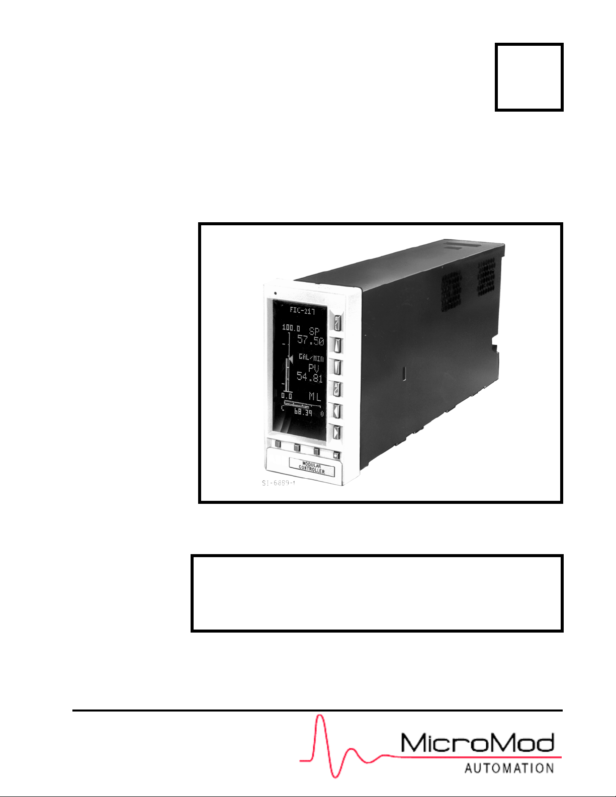
Micro-DCI™ Single Loop Controller
53SL5100A
Rev. 1 Firmware
PN24585
Rev. 1
NOTE:
The purpose of this addendum is to supplement and provide
additional information applicable to the Micro-DCI™ 53SL5100A
Single Loop Controller Instruction Bulletin (PN24469).
Page 2

MicroMod Automation, Inc.
The Company
MicroMod Automation is dedicated to improving customer efficiency by providing the most cost-effective, application-specific process
solutions available. We are a highly responsive, application-focused company with years of expertise in control systems design and
implementation.
We are committed to teamwork, high quality manufacturing, advanced technology and unrivaled service and support.
The quality, accuracy and performance of the Company's products result from over 100 years experience, combined with a continuous
program of innovative design and development to incorporate the latest technology.
Use of Instructions
∆ Warning. An instruction that draws
attention to the risk of injury or death.
❢ Caution. an instruction that draws
attention to the risk of the product,
process, or surroundings.
Although Warning hazards are related to personal injury, and Caution hazards are associated with equipment or property damage, it
must be understood that operation of damaged equipment could, under certain operational conditions, result in degraded process
system performance leading to personal injury or death. Therefore, comply fully with all Warning and Caution notices.
Information in this manual is intended only to assist our customers in the efficient operation of our equipment. Use of this manual for
any other purpose is specifically prohibited and its contents are not to be reproduced in full or part without prior approval of MicroMod
Automation, Inc.
✎Note. Clarification of an instruction
or additional information.
i Information. Further reference for
more detailed information or
technical details.
Licensing, Trademarks and Copyrights
MICRO-DCI™ is a trademark of MicroMod Automation, Inc.
All other brand or product names are trademarks or registered trademarks of their respective holders.
Copyright 2004 MicroMod Automation Inc. [November 2004]
Health and Safety
To ensure that our products are safe and without risk to health, the following points must be noted.
The relevant sections of these instructions must be read carefully before proceeding.
1. Warning Labels on containers and packages must be observed.
2. Installation, operation, maintenance and servicing must only be carried out by suitably trained personnel and in
accordance with the information given or injury or death could result.
3. Normal safety procedures must be taken to avoid the possibility of an accident occurring when operating in conditions
of high pressure and/or temperature.
4. Chemicals must be stored away from heat, protected from temperature extremes and powders kept dry. Normal safe
handling procedures must be used.
5. When disposing of chemicals, ensure that no two chemicals are mixed.
Safety advice concerning the use of the equipment described in this manual may be obtained from the Company address on the back
cover, together with servicing and spares information.
All software, including design, appearance, algorithms and
source codes, is copyrighted by MicroMod Automation, Inc.,
and is owned by MicroMod Automation or its suppliers.
Page 3

53SL5100 Single Loop Controller Rev. 1 Firmware
1.0 APPLICABLE DOCUMENTATION
This addenda publication contains additional information applicable to the Micro-DCI™ 53SL5100A
Instruction Bulletin, SIngle Loop Controller.
1.1 SCOPE OF CHANGES
Contact Closure Output 1 (CCO-1) functionality is added to the 53SL5100A Single Loop Controller as a
result of Revision 1 to the firmware EPROM. CCO-1 operates with Control Strategies 1, 3 and 4 of the
Single Loop Controller. These Control Strategies are respectively the Single Loop (PID) Controller, Ratio
(PID) Controller and Automatic/Manual Station.
Also, as a result of Revision 1 to the firmware EPROM, there are Process Alarm selectable assignments
now available for Contact Closure Output 0 (CCO-0). (The newly added CCO-1 does not have selectable
Process Alarm assignments, but is dedicated only to Process Alarm 2 [PA2].)
2.0 CONTACT CLOSURE OUTPUT 1 (CCO-1)
SPECIFICATIONS
CCO-1 is a solid state device that can be configured as a normally open or normally closed switch. It has a
maximum voltage rating of 30 V dc and a maximum current rating of 50 mA.
2.1 CONTACT CLOSURE OUTPUT 1 (CCO-1) WIRING CONNECTIONS
Connection to CCO-1 is made at pin 18 of TB1. CCO-1 is referenced to power common (pins 11, 14 and
17 of TB1 are power common pins). When CCO-1 is connected to an inductive load, an external arc
suppression network is required for contact protection.
2.2 CONTACT CLOSURE OUTPUT 1 (CCO-1) DATAPOINT MODULE
Datapoint assignments that control CCO-1 operation are described in Table 1 as follows:
Table 1. Contact Closure Output Module 1 (CCO-1)
Title Symbol
Purpose: This module allows the action of CCO-1 to be reversed (normally a closed contact = 1, but can
be changed to = 0).
Contact Output
(Display Only)
Contact Output
Invert
Tag Name
CCO1 L025 0
OINV1 L289 0
COTAG1 A281 CCO1
CCO0
Datapoint
Default Attribute
If CCO-1 = 0 and OINV = 0, then it is open.
If CCO-1 = 0 and OINV = 1 then it is closed.
If CCO-1 = 1 and OINV = 0 then it is closed.
If CCO-1 = 1 and OINV = 1 then it is open.
As shown above, it reverses the action of CCO-1
datapoint.
It is an assignable 10 character name for the cont act
control output.
53SL5100A Single Loop Controller - Addendum 1
Page 4

53SL5100 Single Loop Controller Rev. 1 Firmware
3.0 PROCESS ALARMS 1 AND 2 (PA1 AND PA2)
As with CCO-0, the purpose of CCO-1 is to convert a logic level to a hardware contact cond ition. The logic
levels applicable to CCO-0 are now select able fr om Pro cess Alarm 1 (PA1) alone, or either Process Alarm
1 or 2 (PA1 or PA2). The logic level applicable to CCO-1 is PA2 only. The Process Alarms are configured
with an index value from 0 to 6 that is loaded into the Control Alarm Mode datapoint B335 of the Controller
Module (CON-0). The definitions for PA1 and PA2 therefore vary, depending on the index value of B335.
Descriptions of the PA index values, as well as examples of true conditions, are provided in Table 4-4,
Controller Module (CON-0) of Instruction Bulletin 53SL5100A, Single Loop Controller.
3.1 CCO-0 ALARM SELECT DATAPOINT L084
CCO-0 Alarm Select datapoint L084 determines which Process Alarms affect the state of CCO-0. If L084
is 0, then when PA1 or PA2 is active (1), CCO-0 is active (1). If L084 is 1, then when PA1 is active (1),
CCO-0 is active (1); PA2 has no effect. Table 2 is provided to illustrate the effect of L084 on CCO-0 output
given the states of PA1 and PA2. In Table 2, 1 = active state and 0 = inactive state.
When L084 = 0:
At Line item 1, Neither PA1 nor PA2 = 1; therefore, CCO-0 (L024) = 0.
At Line item 2, PA2 = 1; therefore, CCO-0 (L024) = 1.
At Line item 3, PA1 = 1; therefore, CCO-0 (L024) = 1.
At Line item 4, Either PA1 or PA2 would cause CCO-0 (L024) to equal 1.
When L084 = 1:
At Line item 1, PA1 = 0 and PA2 has no effect; therefore, CCO-0 (L024) = 0.
At Line item 2, PA1 = 0 and PA2 has no effect; therefore, CCO-0 (L024) = 0.
At Line item 3, PA1 = 1 and PA2 has no effect; therefore, CCO-0 (L024) = 1.
At Line item 4, PA1 = 1 and PA2 has no effect; therefore, CCO-0 (L024) = 1.
In Table 2, CCO-1 always has the same state as PA2, because L084 has no ef fect on CCO-1. (CCO-1 is
always dedicated to PA2.)
Table 2. Process Alarm Selections
When L084 = 0
Line
Item
10 0000000
20 1110101
31 0101010
41 1111111
(PA1 or P A2 Affects CCO-0)
PA1
(L110)
PA2
(L111)
CCO-0
(L024)
CCO-1
(L025)
PA1
(L110)
When L084 = 1
(Only PA1 Affects CCO-0)
PA2
(L111)
CCO-0
(L024)
CCO-1
(L025)
✎ Note The output of CCO-0 can be inverted as determined by the setting
of the Contact Output Invert 0 (OINV0) datapoint L288. The affect of
this datapoint on CCO-0 output is described in Table 4-7, Contact
Output Module (CCO) of Instruction Bulletin 53SL5100A, Single
Loop Controller .
2 53SL5100A Single Loop Controller - Addendum
Page 5

Page 6

The Company’s policy is one of continuous product improvement and the
right is reserved to modify the information contained herein without notice, or
to make engineering refinements that may not be reflected in this bulletin.
Micromod Automation assumes no responsibility for errors that may appear
in this manual.
© 2004 MicroMod Automation, Inc. Printed in USA
MicroMod Automation, Inc.
75 Town Centre Drive
Rochester, NY USA 14623
Tel. 585-321-9200
Fax 585-321-9291
www.micromodautomation.com
 Loading...