

Page 1
INSTALLATION & SETUP GUIDE
Data Visualization Software
53PW6000
Micro-PWC® SYSTEM
PN26001 Rev. 1
Page 2
MicroMod Automation, Inc.
The Company
MicroMod Automation is dedicated to improving customer efficiency by providing the most cost-effective, application-specific process
solutions available. We are a highly responsive, application-focused company with years of expertise in control systems design and
implementation.
We are committed to teamwork, high quality manufacturing, advanced technology and unrivaled service and support.
The quality, accuracy and performance of the Company's products result from over 100 years experience, combined with a continuous
program of innovative design and development to incorporate the latest technology.
Use of Instructions
∆ Warning. An instruction that draws
attention to the risk of injury or death.
❢ Caution. an instruction that draws
attention to the risk of the product,
process, or surroundings.
Although Warning hazards are related to personal injury, and Caution hazards are associated with equipment or property damage, it
must be understood that operation of damaged equipment could, under certain operational conditions, result in degraded process
system performance leading to personal injury or death. Therefore, comply fully with all Warning and Caution notices.
Information in this manual is intended only to assist our customers in the efficient operation of our equipment. Use of this manual for
any other purpose is specifically prohibited and its contents are not to be reproduced in full or part without prior approval of MicroMod
Automation, Inc.
✎ Note. Clarification of an instruction
or additional information.
i Information. Further reference for
more detailed information or
technical details.
Licensing, Trademarks and Copyrights
MOD 30 and Micro-PWC are trademarks, and MOD 30ML and Micro-DCI are registered trademarks of MicroMod Automation, Inc.
All other trademaks are the property of their respective owners.
© 2005 MicroMod Automation, Inc. (September 2005)
Health and Safety
To ensure that our products are safe and without risk to health, the following points must be noted.
The relevant sections of these instructions must be read carefully before proceeding.
1. Warning Labels on containers and packages must be observed.
2. Installation, operation, maintenance and servicing must only be carried out by suitably trained personnel and in accordance with
the information given or injury or death could result.
3. Normal safety procedures must be taken to avoid the possibility of an accident occurring when operating in conditions of high
pressure and/or temperature.
4. Chemicals must be stored away from heat, protected from temperature extremes and powders kept dry. Normal safe handling
procedures must be used.
5. When disposing of chemicals, ensure that no two chemicals are mixed.
Safety advice concerning the use of the equipment described in this manual may be obtained from the Company address on the back
cover, together with servicing and spares information.
All software, including design, appearance, algorithms and
source codes, is copyrighted by MicroMod Automation, Inc.,
and is owned by MicroMod Automation or its suppliers.
Page 3

Micro-PWC™ Installation & Setup Guide
Table of Contents
1.0 - INTRODUCTION
1.1 Overview........................................................................................................1
1.2 Intended User................................................................................................2
1.3 Functional Description...................................................................................2
1.3.1 User Interface...................................................................................2
1.3.2 Micro-PWC Management Features..................................................2
1.3.3 Hierarchical Displays........................................................................2
1.3.4 Graphic Configuration ......................................................................3
1.3.5 Historical Database ..........................................................................3
1.3.6 Logging.............................................................................................3
1.3.7 Trending...........................................................................................3
1.3.8 System Status Display......................................................................3
1.3.9 Instrument Configuration..................................................................3
1.3.10 Micro-PWC System Utilities ...........................................................3
1.3.11 Historical Block Data Collection.......................................... ... ... ... ...4
1.3.12 Process Alarms..............................................................................4
1.3.13 Events ............................................................................................4
1.3.14 Message Review............................................................................4
1.3.15 Alarm Groups and External Alarm Annunciation............................4
1.3.16 Printer Review................................................................................4
1.3.17 The @aGlance/IT Application Server interface..............................4
1.4 How to Use This Manual ...............................................................................5
1.5 Glossary of Terms and Abbreviations............................................................5
1.6 Reference Documents...................................................................................9
1.7 Notation Conventions....................................................................................9
2.0 - REQUIREMENTS
2.1 Hardware Requirements.............................................................................. 11
2.1.1 Minimum Hardware Requirements................................................. 11
2.2 Software Requirements...............................................................................11
2.2.1 Requirements.................................................................................11
2.2.1.1 Requirements for Optional Software Packages........... 11
2.3 Micro-DCI Instrument Compatibility.............................................................12
3.0 - INSTALLATION
3.1 Setting Up the Base PC........................ ... ... ... .... ... ... ... ... .... ... ... ... .................13
3.2 Verifying/Installing the Windows Workstation Software...............................13
3.2.1 Verifying Windows Version.............................................................14
3.3 Determine I/O Address for Supervisor Board..............................................15
3.3.1 Windows 2000 Professional...........................................................15
3.3.2 Windows XP Professional ..............................................................16
Contents i
Page 4

Micro-PWC™ Installation & Setup Guide
3.4 Hardware Installation..................................................................................17
3.4.1 Supervisor Board Installation .........................................................17
3.4.1.1 Mechanical Specification................................. ... ... ... ....17
3.4.1.2 Electrical Specification....................... ... ... ... .... ... ... ... ....17
3.4.1.3 Environmental Specification..... ... .... ... ... ... ....... ... ... ... ....17
3.4.1.4 Jumper Settings.......................... .... ... ... ... ... .... ... ..........17
3.4.1.5 Inserting the Supervisor Board ....................................18
3.4.2 Installing the Ethernet Board(s)......................................................19
3.4.3 Installing the Ethernet Drivers and Related Software.....................19
3.4.4 TCP/IP Verification/Installation.......................................................19
3.4.5 Installing the Hardware Key ...........................................................22
3.4.6 Connecting Micro-DCI Instruments to the Base PC.......................22
3.4.6.1 Connecting to a Single 53MC5000 Controller..............23
3.4.6.2 Connecting a COM Port to a Datalink................... ... ....23
3.4.6.3 Connecting the Micro-PWC System to the Datalink Network23
3.4.6.4 Connecting the Micro-PWC System to the Microlink Network24
3.4.7 Verifying System Configuration......................................................28
3.4.7.1 Verifying Version, Processor Type and Memory Amount28
3.4.7.2 Verify Display Configuration........ .... ... ... ... ... .... ... ... ... ....29
3.4.7.3 Verify Configuration of Printer Spool Options...............29
3.4.7.4 Verify Configuration of Tasking Option.........................30
3.4.7.5 Verify Configuration of Desktop Options............ ... ... ....30
3.4.7.6 Verify Taskbar Options... .... ... ... ... .... ... ... ... ... .... ... ... ... ....31
3.4.7.7 Verify Power Management Options .............................31
3.5 Installing the Micro-PWC Software..............................................................31
3.5.1 Micro-PWC Mode Installation..................................... ... .... ... ... ... ....32
3.5.1.1 Pre-Setup Procedure ............................... ... .... ... ... ... ....32
3.5.1.2 Beginning Micro-DCI Master Setup for Full Micro-PWC Operation
.............................................................................32
3.5.1.3 Beginning Micro-PWC Installation................................32
3.5.1.4 Micro-PWC Setup ................................. ... ... .... ... ... ... ....33
3.5.1.5 The SETUP Window....................................................33
3.5.1.6 Copying Micro-PWC Files.................. ... ... ... .... ... ... ... ....33
3.5.1.7 Installation Options............................................. ... ... ....34
3.5.1.8 Installing Micro-PWC License Keys.............................34
3.5.1.9 Choosing Location for the Micro-DCI Portion of Micro-PWC
System.................................................................34
3.5.1.10 New Program Group/Program Folder........................35
3.5.1.11 Adding Micro-DCI Networks.......................................35
3.5.2 Micro-PWC Client Installation Mode...............................................36
3.5.2.1 Pre-Setup Procedure ............................... ... .... ... ... ... ....36
3.5.2.2 Beginning Micro-DCI Master Setup .............................36
3.5.2.3 Beginning Micro-PWC Installation................................36
ii Contents
Page 5

Micro-PWC™ Installation & Setup Guide
3.5.2.4 Micro-PWC Setup ........................................................36
3.5.2.5 The SETUP Window....................................................37
3.5.2.6 Copying Micro-PWC Files............................................37
3.5.2.7 Installation Options.......................................................37
3.5.2.8 Installing Micro-PWC Client License Key . ... .... ... ... ... ... .38
3.5.2.9 Select a Program Folder..............................................38
3.5.3 Microsoft Excel Installation Requirements......................................38
3.5.3.1 Add-in Functions for Microsoft Excel............................39
3.5.3.2 Printing Microsoft Excel Spreadsheets.........................39
4.0 - START-UP and OPERATION
4.1 Micro-PWC Startup......................................................................................41
4.1.1 Startup Options...............................................................................41
4.1.2 Micro-PWC Program Group.... ... ... ... .... ... ... ... ... .... ... ... ... .... ... ... ... ... .41
4.1.3 Licensing During Initial Startup.......................................................43
4.1.4 Micro-PWC Network Service Startup .............................................43
4.2 Stopping the Micro-PWC Software..............................................................44
4.2.1 Closing the Micro-PWC System Windows .....................................44
4.2.2 Stopping the Micro-PWC System Network Service........................44
4.3 The Capuser Account..................................................................................45
4.4 Re-installing the Micro-PWC Software ........................................................46
4.5 Removing a Micro-PWC Installation............................................................46
4.6 Network Time, Time Zones, and Time Adjustment......................................47
4.6.1 Verifying Consistent Network GMT
.................................................................................................47
4.6.2 Time Settings..................................................................................47
4.6.2.1 Changing the Time Zone Setting .................................47
4.6.2.2 Daylight Saving Time...................................................48
4.6.3 Time Adjustment.............................................................................48
4.7 Naming Conventions...................................................................................49
4.7.1 TAGs ..............................................................................................49
4.7.1.1 Types of TAGs..............................................................49
4.7.1.2 Special Considerations in Using TAGnames................49
4.7.2 ATOMS...........................................................................................50
4.7.2.1 Types of ATOMnames..................................................50
4.8 Other Considerations...................................................................................50
5.0 - TROUBLE-SHOOTING
5.1 General Recommendations.........................................................................51
5.2 Diagnostic Messages ..................................................................................52
5.2.1 Windows Messages .......................................................................52
5.2.2 Micro-PWC System Diagnostic Output ..........................................52
5.3 Technical Support........................................................................................52
Contents iii
Page 6

Micro-PWC™ Installation & Setup Guide
6.0 - MAINTENANCE
6.1 The Basic Menu.................................... ... ... ... .... ... ... ... .... .............................53
6.1.1 The Display Log File Menu Item.....................................................53
6.1.2 The Set System Language Menu Item...........................................54
6.1.3 Exit .................................................................................................54
6.2 The String Files Menu .................................................................................54
6.2.1 Modify a Language String File........................................................54
6.2.2 Save Changes to a Language String File.......................................55
6.2.3 Create a Language Directory.........................................................55
6.2.4 Verify a Language Directory...........................................................55
6.2.5 Update a Language Directory ........................................................55
6.2.6 Delete a Language Directory..........................................................56
6.3 The License Administration Menu ...............................................................57
6.3.1 Accessing the License Administration Utilities ...............................57
6.3.1.1 Add a Licensed Feature...............................................57
6.3.1.2 Modify Licensing of an Existing Feature ......................57
6.3.1.3 Delete a Licensed Feature...........................................57
6.3.1.4 Save Licensing Data for Licensed Features ................57
6.3.2 Show Machine/Host ID...................................................................58
7.0 - SUPPORT SERVICES
7.1 Software Maintenance Agreement..............................................................59
7.2 Training.......................... ....................................... ... ... .... ... ... ... ....................59
7.3 Replacement Parts.. ... ... ... .... ... ... ... ... .... .......................................... ... ... ... ....59
7.4 Technical Documentation .................................. ... ... ....................................62
8.0 - THE @aGlance/IT SERVER INTERFACE
8.1 Overview........................ ....................................... ... ... .... ... ... .......................63
8.1.1 General Information About @aGlance/IT.......................................63
8.1.2 The @aGlance/IT API for Micro-DCI..............................................63
8.1.3 Micro-DCI @aGlance/IT Server Requirements - Micro-PWC Version64
8.2 THE @aGlance/IT Server Operation...........................................................65
8.2.1 Configuring the @aGlance/IT Server Internal Interface.................65
8.2.1.1 Registering Server Nodes.................. ... ... ... .... ... ... ... ....65
8.2.2 Starting a Server and Server Names..............................................66
8.2.2.1 Starting a Server with Non-Default Options .................66
8.3 Security for the @aGlance/IT Server...........................................................68
8.3.1 Security for Access to the @aGlance/IT Server for Micro-DCI ......68
8.3.2 Security for Micro-DCI Database Access.......................................68
8.4 Supported @aGlance/IT Client Applications...............................................68
iv Contents
Page 7

Micro-PWC™ Installation & Setup Guide
List of Figures
Figure 3-1. I/O Address List on Windows, Windows 2000 Professional ...........15
Figure 3-2. I/O Address List on Windows XP Professional ....... ... ... .... ... ...... ... .16
Figure 3-3. Jumper Settings, Supervisor Board ...............................................18
Figure 3-4. My Network Places Icon and Menu ................................................20
Figure 3-5. Configuring the IP Address, Steps 2 and 3 ....................................20
Figure 3-6. Internet Protocol (TCP/IP) Properties ............................................21
Figure 3-7. Hardware Key for Use with Micr o- PWC Syst em Software
(Parallel Port Version) ...................................................................22
Figure 3-8. Connecting the Computer’s COM Port to the Datalink ...................25
Figure 3-9. 53SU6000Datalink SUPERVISOR Card to
Datalink Interconnection Diagram (ID-53-1610) .............................26
Figure 3-10. 53SU6000 Microlink SUPERVISOR Card to Microlink
Interconnection Diagram (ID-53-1597) ..........................................27
Figure 4-1. Micro-PWC Program Group ...........................................................41
Figure 4-2. Time Adjustment Window ..................................................... ... ... ... .48
List of Tables
Table 3-1. License Type and Operational Mode Interaction............................. 32
Table 5-1. Micro-PWC Installation and Setup Problems and
Recommendations........................................................................... 51
Table 7-1. Interconnection Terminal Boards (ITB)...... ... ... ... .... ... ... ... ................ 60
Table 7-2. Supervisor Cards............................................................................. 60
Table 7-3. Firmware Upgrade Kits.....................................................................60
Table 7-4. Cable Assemblies 61
Table 8-1. Options for Use When Starting a Server 66
Contents v
Page 8

Micro-PWC™ Installation & Setup Guide
vi Contents
Page 9

READ FIRST
Micro-PWC™ Installation & Setup Guide
∆ WARNING
INSTRUCTION MANUALS
Do not install, maintain, or operate this equipment without
reading, understanding and following the proper MicroMod
Automation Inc. instructions and manuals, otherwise injury or
damage may result.
Read these instructions before starting installation;
save these instructions for future reference.
Contacting MicroMod Automation Inc.
Should assistance be required with any MicroMod Automation Inc. product, use the follo wing contact
information.
Telephone:
MicroMod Automation Inc., Rochester NY:
Phone: 1 (585) 321-9200
Fax: 1 (585) 321-9291
MicroMod Automation Inc., Southampton, PA:
Phone: 1 (215) 355-4377
Fax: 1 (215) 355-4378
E-Mail:
support@micmod.com
Read First vii
Page 10

Micro-PWC™ Installation & Setup Guide
viii Read First
Page 11

Micro-PWC™ Installation & Setup Guide
1.0 INTRODUCTION
The Micro-PWC™ system is a software product designed to run on an Intel Pentium®-based Personal
®
Computer running the Microsoft
system. This product provides a process control operator interface for the following Micro-DCI
ments.
Windows® 2000 Professional or Windows® XP Professional operating
®
instru-
53MC5000 Process Control Station
53SL6000 Single Loop Controller
50XM2000 Magnetic Flowmeter
53MC4000 Four Loop Controller
53MC2000 Single Loop Controller
50KM2000 Chameleon
53MC1000 Single Loop Controller
The heart of this product is a suite of applications that provide easy to use, state -of-the-art displays and
tools to a plant operator . All o f the applications combine a rich se t of default st arting point s with the cap ability to completely customize the applications to meet any operational need.
The Pentium processor is the minimum level processor for acceptable performance. Hardware from several vendors has been qualified and is supported for use with the Micro-PWC system softwa re. The list of
hardware requirements and approved ven dors is contained in Section 2.1, Hardware Requirements, in this
Guide. In addition to the computer, related har dware component s are available for use with the Micro-PWC
system. Several styles of keyboards are available along with a variety of cursor control devices. Interface
cards for Micro-DCI Datalink and Microlink networks are available to provide high performance interfaces
to the Micro-DCI instrument line.
1.1 Overview
Micro-DCI is a distributed process control and information management system which provides the capability to divide process functions among many system components to provide operating flexibility, system
reliability, reduced system costs and ease of implementation. Distribution combined with redundancy also
allows system control and operating functions to be divided among system elements to increase reliability
and flexibility and to reduce risk.
Automation of most processes requires more than control at the unit operations level. The system must
also include an inherent ability to provide process management functions such as scheduling and graphical presentation of plant process conditions as well as reporting functions. The Micro-PWC system is a
human/machine interface to this system, providing the Process Operator, Process Engineer, Instrument
Engineer and Maintenance personnel with global access to all process and system p arameters required by
each to perform their respective tasks.
The Micro-PWC system provides the Process Operator with a window to the process. Using interactive
process graphics and hierarchical displays, the Proce ss Oper ator can mon itor and contr ol all analo g loop s
and discrete devices interfaced to the network, as well as sequential batch operations.
The Micro-PWC system provides the Engineer with an interface through which to configure and change
Graphic and Hierarchical Displays, database I/O, instrument process control functions and sequences,
Log (report) formats, and security fe atures (including access levels for operating personnel). Most changes
Introduction 1
Page 12

Micro-PWC™ Installation & Setup Guide
are immediate, on-line and network-wide, requiring no compilation time before downloading and therefore
no interruption of the process.
The Micro-PWC system provides Maintenance Personnel with the capability to globally monitor the operating status of any system component on the network, and to diagn ose component failures from any MicroPWC system.
1.2 Intended User
The Micro-PWC Installation and Setup Guide is intended for use by personnel engaged in the installation
of the hardware and software components of the Micro-PWC system (PWC).
It is the job of the Micro-PWC system to communicate with the various Micr o- DCI instrumen ts that may be
connected. It is necessary to have some degree of familiarity with the configuration and operation of the
attached instruments in order to understand the function of the Micro-PWC system.
1.3 Functional Description
1.3.1 User Interface
The Micro-PWC system provides the Process Operator, Engineer and Maintenance Technician with a window-based interface to both the process and the Micro-PWC system itself. The window environment on
the Micro-PWC system is based on the Windows operating system from Microsoft.
1.3.2 Micro-PWC Management Features
The Micro-PWC system allows the user to configure many items which aid in managing use of the system.
These include:
• Security Features
• User Logins
• Network Parameters
• Archival Groups
• Messages
• Message Routing
• Network Device Assignment
See the Micro-PWC Configuration Guide for further information on these items.
1.3.3 Hierarchical Displays
Hierarchical displays are a set of preconfigured, network-wide graphical representations emulating traditional instrument displays. A three tiered hierarchy of displays exists to provide the user with infor mation
about the process. This hierarchy consists of Summa ry, Group and Point displays.
A Summary Display provides an overview of 24 groups, arranged in 6 rows of 4 blocks. Ther e ar e 10 0 0
Summary Displays available.
A Group Display provides an operation overview of 4, 6 or 8 points simultaneously. All process control
actions and alarm acknowledgment for points within a group can be performed from the Group Display on
a point-by-point basis.
2 Introduction
Page 13

Micro-PWC™ Installation & Setup Guide
A Point Display provides the most detailed information and operation functions about a single instrument
function block in the Hierarchical Display system. From this level the operator can perform regulatory
changes. Hierarchical Display configuration is discussed in the Micro-PWC Configuration Guide.
1.3.4 Graphic Configuration
Up to 10,000 network-wide graphic displays can be configured using the Micro-PWC system. Because
they are network-wide, a graphic display can be configured on any Micro-PWC system; a copy of the file
containing the graphic is then distributed to all Micro-PWC systems on the network whenever a graphic is
saved or installed. Graphic Configuration is discussed in the Micro-PWC Configuration Guide.
1.3.5 Historical Database
The Historical Database provides the means to collect data from the instruments and store it for use by
various other applications on the Micro-PWC system, such as Logging, Trending and Data Archiving. Historical Data collection is an option on the Micro-PWC system. Configuration of Historical Database data
collection is discussed in the Micro-PWC Configuration Guide.
1.3.6 Logging
Logs are used to collect and format data for use in reports and spreadsheet calculations. The three types
of logs available on the Micro-PWC system include Summary Logs, Event Logs and Spreadsheet Logs.
Spreadsheet logs are an optional feature, configured via Microsoft Excel on the Micro-PWC system. Logs
are available network-wide. Log configuration is discussed in the Micro-PWC Configuration Guide.
1.3.7 Trending
Trending functions display the values of from 1 to 8 points in an analog trend format similar to that presented by a conventional strip chart recorder. Three types of trend recording are provided on the MicroPWC system, including Current Trending, Historical Trending and Archival Trending. Trend displays are
network-wide. Trend configuration is discussed in the Micro-PWC Configuration Guide.
1.3.8 System Status Display
The System Status Display provides an overview of the nodes connected to the Micro-DCI console network. The System Status display also provides access to instrument configuration, which is discussed in
Chapter 10 of the Micro-PWC Configuration Guide. The System Status Display is described in the
Micro-PWC Configuration Guide.
1.3.9 Instrument Configuration
The Micro-PWC system can be used to configure the various Micro-DCI instruments, and can also be used
to updump or download the instrument database, as well as F-tran program files. The mechanics of using
the Micro-PWC system to perform these functions and other services such as file management and database structure verification are provided in the Micro-PWC Configuration Guide.
1.3.10 Micro-PWC System Utilities
A number of useful maintenance and information management functions are provided as Utilities.
Utilities available on the Micro-PWC system include: Backup/Restore, Database Maintenance utilities,
Alarm Groups, Release All Configuration Locks, Other Applications, (Micro-PWC) System Help, User
Help, Quick Keys, CRT Context Keys, and CRT Print.
Utilities of use to personnel involved in configuration activities are discussed in the Micro-PWC Configura-
tion Guide. Utilities of use to the process operator are discussed in the Micro-PWC Operator's Manual.
Introduction 3
Page 14

Micro-PWC™ Installation & Setup Guide
(Some utilities which are of use to both the configurer and the operator [e.g., CRT Print, System Help, User
Help, and so on] are discussed in both manuals.)
1.3.1 1 Historical Block Data Collection
The optional Historical Block Database is designed for the efficient collection of data from a large number
of instrument tag.atoms. Like the data collected in the Historical Database, the Historical Block data is
stored for use by other applications, such as Logging, Trending and Data Archiving. Conf iguration of this
item is discussed in the Micro-PWC Configuration Guide.
1.3.12 Process Alarms
A Process Alarm is generated when a process variable is in an abnormal condition. Process Alarms are
displayed in the top two lines of the Mini-Alarm window and in the Alarm Review display, and are accomp anied by audible alarms. Process Alarms are discussed in the Micro-PWC Operator's Manual.
1.3.13 Events
System Events occur when a problem or change of state is detected within the system, as opposed to
abnormal conditions, problems, or changes of state associated with the process which is being monitored.
System Event messages are displayed in the third line of the Mini-Alarm window, the Event Review display, and the Event Historian. Events are discussed in the Micro-PWC Operator's Manual.
1.3.14 Message Review
Operator Messages are used to provide the operator with information and instr uctions for performing
actions, and can be generated from both the instrument and from the Micro-PWC system. Operator Messages are displayed in the fourth line of the Mini-Alarm window and in the Me ssage Review display, and
can be accompanied by an audible alarm. Message Review is discussed in the Micro-PWC Operator's
Manual.
1.3.15 Alarm Groups and External Alarm Annunciation
An Alarm Group is a list of tagname.atoms, each with an associated value, which are downloaded to the
instrument database; this action is triggered by the occurrence of alarm messages which pass through a
user-configurable filter. This feature can be used to trigger external alarm annunciators when the downloaded values are used to change the value of the Discrete Output (DO) modules in the instrument database. See your system administrator for information on use of this feature at your site.
1.3.16 Printer Review
Messages which have been sent to a printer or to a file can be displayed using the Printer Review display.
Printer Review is discussed in the Micro-PWC Operator's Manual.
1.3.17 The @aGlance/IT Application Server interface
The @aGlance/IT server interface is an optional utility which provides a live data link between a node and
a variety of software applications resident on other distributed control systems, supervisory control systems, personal computers, and so on.
There are two aspects to @aGlance/IT Server configuration: external interface configuration and internal
interface configuration. The @aGlance/IT external interface configuration is used to identify tagnames and
attributes (atoms) in the Global Database, and is described in the Micro-PWC Configuration Guide.
4 Introduction
Page 15

Micro-PWC™ Installation & Setup Guide
The @aGlance/IT internal interface configuration is used to identify the nodes on which @aGlance/IT servers will run. Details on requirements for and configuration of the internal interface for this utility on the
Micro-PWC system are provided in this document, the Micro-PWC Installation and Setup Guide.
1.4 How to Use This Manual
The Micro-PWC Installation and Setup Guide is designed to provide the user with the information necessary to install those hardware and software components of the Micro-PWC system supplied by MicroMod
Automation, Inc.
Section 1.0, INTRODUCTION, describes provides an introduction and overview of the Micro-PWC system.
It also includes a brief glossary, and a list of associated documents.
Section 2.0, REQUIREMENTS, describes the minimum and recommended hardware r equire ment s for the
Micro-PWC system.
Section 3.0, INSTALLATION, describes hardware and software installation procedures.
Section 4.0, START-UP and OPERATION, describes Micro-PWC system operating procedures.
Section 5.0, TROUBLE-SHOOTING, describes trouble-shooting techniques.
Section 6.0, MAINTENANCE, describes the Maintenance Menu subsystem.
Section 7.0, SUPPORT SERVICES, describes support services.
Section 8.0, THE @aGlance/IT SERVER INTERF ACE, describes configuration of the @aGlance/IT Serv er
Interface.
1.5 Glossary of Terms and Abbreviations
This Glossary provides definition for terms used in the Micro-PWC Installation and Setup Guide. Where
alternate usage is defined in the Glossary, the first listed term is considered the preferred usage.
Active Window. The active window is the window with keyboard focus, which receives all keyboard input,
regardless of pointer location. What is typed appears in the active window. If there is no active window,
what is typed is lost. There can be only one active window at a time on a Micro-PWC system monitor.
Area. A functional partition of the Process. Each Micro-DCI network can be assigned to an Area. MicroPWC system functions can then be assigned by Area.
Atom. A single data element in the global database. Atoms can exist in various forms, including (but not
limited to) a single bit (e.g., Auto/Manual), a floating point number, a tagname or a multi- character legend;
there is no pre-defined limit to the size of an atom. See also Module.
Banner. A header page which precedes a printout, which contains identifying information. This is especially useful when the user initiating the printout is not in the immediate vicinity of the printer.
Button. A graphical object in a window that has a three dimensional appearance and acts as a pushbutton. When the user selects or "presses" the button (mouse cursor is placed on button and mouse button is
pressed), its three dimensional appearance inverts, giving the illusion that the button has been pressed.
When the user releases the button, the button appearance returns to normal.
Cancel Button. A pushbutton in some windows which closes the window without implementing any
changes.
Cascading Menu. A submenu which provides selections that amplify the parent selection on a pull-down
or pop-up menu.
Introduction 5
Page 16

Micro-PWC™ Installation & Setup Guide
Check Button. A type of graphic control button used to select settings which are not mutually exclusive.
The visual cue to indicate selection is that a selected button is filled in or checked.
Child Window. A sub-window opened from a parent window. Easily recognized examples are pop-up
menus and help screens. Also known as a pop-up window.
Click. The act of pressing and releasing a mouse button without moving the pointer. The term comes from
the fact that pressing and releasing the mouse buttons produces a clicking sound.
Close Button. The Close button is used to close a window when there are no changes and no data to
save.
Combo Box. See Drop-down Combo Box.
Control Key. The keyboard key labelled CONTROL or <C
TRL> and used as a modifier key.
CRT (Cathode Ray Tube). The Micro-PWC system monitor. The terms CRT and terminal are sometimes
used interchangeably in the documentation.
Cursor. A graphical image, usually an I-beam, arrow, or rectangle, that shows the location where text will
appear on the screen when keys on the keyboard are typed, or where a selection will be made when using
the Select mouse button or <E
NTER> key on the Micro-PWC system Keyboard.
Database. A set of information that resides in a n ode on the network. Several data bases may reside at a
node. See also Global Data Base.
Data Dictionary. A table containing all the rules required to access and configure a data base. The Data
Dictionary resides in the node with the data base.
Dialog Box. A secondary window which is displayed as a result of a user action and contains graphical
controls such as toggle buttons, radio buttons or other pushbuttons.
Digital I/O. Input/output data which is encoded in a digital format (as in ser ial or parallel bytes or words).
See also Discrete I/O.
Discrete I/O. Used to designate two state process input/output types. See also Digital I/O.
Drag. A type of interaction in which the mouse Select button is pressed and held. The mouse is then
moved so that the pointer is "dragged" to the desired location on the screen; the Select button is then
released to complete the action.
Drop-down Combo Box. A drop-down combo box consists of a text entry box and drop-down pushbut-
ton; clicking on the pushbutton provides access to a drop-down list box of selections.
Entry Box. An area used for text entry. An entry box is typically part of a dialog box.
Full Travel Keyboard. A keyboard with separate and distinct keys; each key is capable of complete and
independent travel.
GDBA (Global Data Base Access). See Global DBA.
Global Data Base. The set of all data bases which are accessible by the Micro-PWC product. A foreign
data base joins the Micro-PWC Global Data Base through the mechanisms of Global DBA.
Global DBA (Global Data Base Access, alternate usage is GDBA). The convention for providing access
to data base atoms.
GMS (Graphical Modeling System). A application program licensed from SL Corporation. GMS is used
to create graphical displays on the Micro-PWC system. Each Micro-PWC system incorporates an R T (run time) license to utilize GMS models.
Highlight. An item selected from the list in a list box will be highlighted by a background color different
from the rest of the list box. To highlight an item, position the pointer on that item and click the left mouse
button.
6 Introduction
Page 17

Micro-PWC™ Installation & Setup Guide
ISO (International Standardization Organization). A worldwide federation of national member bodies
providing guidelines for the development of standards.
Icon. An icon is a representation (in miniature), on the monitor screen, of a larger entity, such as a window.
To iconify a window (change it from full size to a small visual representation), the user presses an iconify
button located in the upper right corner of the window's frame. The procedure is rever sible.
Keyboard Focus. The Micro-PWC system uses the "explicit" or "click-to-type" model of keyboar d focus ;
that is, the user must position the pointer (also known as the "mouse cursor") somewhere on the window
which is to receive input from the keyboard (or other input device), and press the lef t mouse butto n once to
select the window. The color of the title bar of the selected window will then change, and that window will
become the active window. The active window receives all keyboard and mouse input.
License. See Software License.
List Box. A list box is an area within a window which provides the user with a scrollable list of options from
which to choose.
Lower. To move a window to the bottom of the window stack in the work area.
Maximize. To enlarge a window to its largest allowable size.
Menu Bar. An area located below the title bar on an Operator Window, which provides the user with sev-
eral options, including Exit, Select and Help.
Menu Pushbutton. A pushbutton on the System Window, which causes a pull-down menu to appear.
Message Box. Message box is the generic name for any dialog box that provides information, gives the
current state of a work in progress, asks a question, issues a warning, or draws attention to an error.
Micro-PWC system. The Micro-PWC system is a Windows-based system which provides the process
control operator with an interface to the distributed control system.
Mini-Alarm Window. The Mini-Alarm Window is located to the right of the System Window on the Micro-
PWC monitor screen. The Mini-Alarm Window automatically appears upon system start-up and is visible at
all times. The Mini-Alarm Window provides a title bar, an alarm display area, an event display area, Alarm
Acknowledge buttons to acknowledge alarms and events, and a Filter button and More Alarms indicator.
Modal Pop-up Window . A pop-up window which require s input from the user. Until the user responds and
closes the modal pop-up window, the parent window will reject any user input.
Model. When used in the graphical context of GMS, a model is an object or group of objects. Models can
be used as objects in other models.
Modifier Key. A key which, when pressed in conjunction with another key, changes the meaning of the
other key. <C
TRL>, <ALT>, and <SHIFT> are modifier keys.
Module. An atom or group of atoms which are combined into a data base structure.
Mouse. A small device with three buttons on top, connected by a cable to the PC on which the Micro-
PWC system software resides. When moved on the surface of a desk or table, the mouse allows the user
to point to locations on the monitor screen and to issue commands by pressin g buttons. The user point s to
a screen location by controlling the position of an image on the screen known as a pointer or mouse cur-
sor. By positioning the pointer on an item and pressing the app ropriate mouse button, the user can select
the desired option. The left mouse button is used for most operations on the Micro-PWC system.
Mouse Button. One of the buttons on the mouse.
Mouse Cursor. (See Pointer.)
Node. A node is a unit or system on the Micro-PWC system Ethernet.
Object. When used in the graphical context of GMS, an entity such as a circle, rectangle, or text field.
Introduction 7
Page 18

Micro-PWC™ Installation & Setup Guide
Operator Window. Located on the Micro-PWC system monitor screen below the System window and
Mini-Alarm window, the Operator Window provides the operator interface to the process, and displays program output from Operator Window applications such as hierarchical displays, trends, graphics, alarm
review, etc. The Operator Window is composed of a title bar, a menu bar, and a display area. Up to four
Operator windows may be present simultaneously on a Micro-PWC system display terminal.
Option Menu. A list of items selectable via associated check or toggle buttons.
Parent Window. The top level window placed on the screen when a new application is started. When a
parent window is closed (removed from display), all child windows are also closed. The Micro- PWC system
keyboard (alphanumeric keys, mouse, etc.) is focused on one parent window, with the color of the parent
window border indicating the focus.
PEM. Process Event Message.
Pointer. A small, mobile image on the monitor screen, controlled by the mouse, which allows the user to
point to specific locations on the monitor screen. The user positions the pointer by moving the mo use on a
desk or tabletop. Also known as the mouse cursor.
Pop-up Menu. A menu which provides no visual clue to its presence, but simply "pops up" when a particular action is performed.
Pop-up Window. A sub-window opened from a parent window. Easily recognized examples are pop-up
menus and help screens. See also Modal Pop-up Window and Child Window.
Pull-down Menu. A menu that is "pulled down" from a window's menu bar.
Pushbutton. A pushbutton is an area of the screen surrounded by a border shadow. When the pushbutton
is selected, the shadow moves to give the illusion that the pushbutton has been pressed in. When the
pushbutton is unselected, the shadow moves to give the appearance that the pushbutton has been
released. Pushbuttons can contain text, numbers, colors or symbols such as directional arrows. For example, the company logo appears on a button in the System Window.
Quick Key . A menu item a ccessed via the SELECT item on the Operator Wind ow menu bar, which, when
pressed, provides the user with the ability to vector directly to one of 64 possible displays.
Radio Button. A graphic control button that simulates the buttons found on an actual car radio. Each button represents a mutually exclusive selection. Radio buttons are typically used to set states or modes.
Redraw Button. A selection on the Operator Window menu bar which allows the user to redraw the
screen on demand.
Resize Handles. The function of resize handles is to resize a window and the display it contains. The
resize handles form a frame which consists of eight separate pieces: the top, bottom, two sides and the
four corners of the frame.
Screen. The monitor screen of a Micro-PWC system monitor.
Scroll Bar. A scroll bar is a feature which allows the user to view data that is too large to be viewed in its
entirety in the associated work area. (The work area typically contains data such as a list or block of text.)
A scroll bar consists of two arrows pointing in opposite directions at each end of a small rectangle. The
rectangle is called the scroll region. A smaller rectangle called the slider is located within the scroll region.
Scroll bars can be located both horizontally and vertically. Horizontal scroll bars are located at the bottom
edge of a work area; vertical scroll bars appear at the right edge.
Scroll Region. The rectangular portion of a Scroll Bar that contains the two arrows and the slider. See
Scroll Bar.
SL-GMS (SL Corporation Graphical Modeling System). See GMS.
Slider. See Scroll Bar.
8 Introduction
Page 19

Micro-PWC™ Installation & Setup Guide
Software License. A software license conve ys to th e purchaser the right to use a defined software prod-
uct. Software licenses are enforced with a Software Licensing Manager program.
Stippling. The technique of displaying items in a lighter shade (typically gray) to denote some special
characteristic. This method is employed in the Micro-PWC system to display items which reside on a particular menu, but which are not currently available to the user (typically, because of access level considerations).
System Window. A small window located at the top left corner of the Micro-PWC system monitor display.
It appears automatically upon system start-up, an d is visible at all times (unless deliberately covered by the
user). The System Window provides a date/time indicator and a menu button for access to other system
features and utilities.
Title Bar. An area located at the top of a window, which provides information to identify the window.
Touchscreen. A monitor with a screen that is sensitive to touch, allowing selections to be made without
the use of a keyboard, mouse or trackball.
Trackball. A ball, movable about its center, that is used to position the pointer on the monitor screen.
(Synonymous with control ball.)
Window. A rectangular section of the screen, which has a background color and a border. Windows may
also incorporate scroll bars, title bars, an d other hig her-level u ser interface comp onent s. See also System
Window, Mini-Alarm Window, Operator Window, Parent Window, and Child Window.
1.6 Reference Documents
•The Micro-PWC Configuration Guide, which provides information for the person configuring
the Micro-PWC system.
•The Micro-PWC Operator's Manual, which provides information for the operator of a
configured Micro-PWC system.
1.7 Notation Conventions
Window titles, menu items, and labels on tabs are shown in italic type.
The labels on keys and pushbuttons are shown in bold type.
Text that the user types in, computer responses, and example text are shown in constant width type.
The term pushbutton refers to video buttons with a three-dimensional appearance; selecting such buttons
via the cursor positioning device (mouse or trackball) or keyboard causes them to appear "pushed in".
Many of the windows which appear on the Micro-PWC system contain buttons labelled Ok, Cancel and
Close. The Ok button is used to save data and close the window in which it app ears. The Cancel button is
used when data is not to be saved, and the current window closed. The Close button is used when there is
no data to be saved, and the current window is to be closed (except in the case of dialog pop-up windows,
which are closed using an Ok button).
Introduction 9
Page 20

Micro-PWC™ Installation & Setup Guide
10 Introduction
Page 21

Micro-PWC™ Installation & Setup Guide
2.0 REQUIREMENTS
2.1 Hardware Requirements
2.1.1 Minimum Hardware Requirements
The following minimum hardware requirements must be met to successfully load and run the Micro-PWC
system software. These include:
• A personal computer (PC) that meets the minimum requirements for running the Windows
operating system. (See Section 2.2, Software Requ irements.)
• 512 MB of memory.
• A 4 GB disk drive.
• A CD-ROM drive. (The Micro-PWC system software is distributed on CD-ROM.)
• A video board and monitor which support 256 colors (8 bit mode) at 1024 x 768 pixel
resolution. A video board and monitor which suppor t 65 K colo rs (1 6 bit mode ) ar e
recommended.
• A single Ethernet communication channel.
• A parallel port or USB port for printing and hardware key installation.
• A DAT tape drive is required on Micro-PWC systems on which large backup and restore
operations will be performed.
• A full size ISA bus slot is required for each installed Supervisor card.
2.2 Software Requirements
The software versions required for the Micro-PWC system are discussed in this sub-section, as well as
requirements for compatibility between the Micro-PWC system and other Micro-DCI products.
2.2.1 Requirements
The following software versions are required for the Micro-PWC system, Release 4.0:
• Windows 2000 Professional or Windows XP Professional
• 53MC5000 Firmware, Rev. 5
• 53SL6000 Firmware, Rev. 1
2.2.1.1 Requirements for Optional Software Packages
Optional software packages supported on the Micro-PWC system require the following software versions:
• Microsoft EXCEL
• @aGlance/IT, Version 3.2 (or later)
• Loopmaster, Version 4.0
• Micro-Tools, Version 4.0
Requirements 11
Page 22

Micro-PWC™ Installation & Setup Guide
2.3 Micro-DCI Instrument Compatibility
In order to use Release 4.0 of the 53SU6000 Micro-DCI Com munication Se rvices system so f twa re, th e following changes or upgrades must be made to any Micro-DCI instruments to be used with the new software:
• Supervisor cards require an upgrade to REV5 of the firmware
• 53MC5000 units with firmware levels of REV0 through REV4 generate pre-acknowled ged
alarms. REV5 firmware is available that enables ala rm s to be ack no wle dg e d by the op er at or.
• 53SL6000 units with REV0 firmware generate pre-acknowledged alarms. REV1 firmware is
available that enables alarms to be acknowledged by the operator.
• The following control modules can only be used in Hierarchical Displays by connecting them to
CON modules on the Supervisor Card:
53MC1000
53MC2000
53MC4000
50KM2000
12 Requirements
Page 23

Micro-PWC™ Installation & Setup Guide
3.0 INSTALLATION
Micro-PWC is composed of several hardware and software components integrated into a base personal
computer (PC). This section provides information on installing these hardware and software components.
Some of the instructions for this installation will be included with the hardware or software components and
are not addressed in this Installation and Setup Guide. The installation order of these component s is significant, and should be done in the following sequence:
1. Set up the base PC. (See Section 3.1.)
2. Ve rify that the base PC is running the Windows 2000 Professional W orkstation or Windows XP
Professional Workstation operating system.
3. Determine the available I/O addresses that can be used when installing a supervisor board.
(See Section 3.3.)
4. Install the optional Micro-DCI network interface board. This can be either a Datalink
Supervisor board, Microlink Supervisor board, or Redundant Microlink Supervisor board pair.
These Supervisor boards enable multiple instruments to be networked together and
connected to this base PC. (See Section 3.4.1.)
5. Install the Ethernet network interface board. This board enables the base PC to connect to an
Ethernet network. (See Section 3.4.2.)
6. Install the drivers and any related software for the Ethernet network interface board(s). A
diskette containing drivers for each of the network interface board(s) will come with the
network board(s). These drivers will enable the base PC to recognize which network board(s)
have been installed. (See Section 3.4.3.)
7. Verify that the TCP/IP network protocols have been installed on the base PC. If TCP/IP has
not been installed on this PC, install it. (See Section 3.4.4.)
8. Install the Micro-PWC system hardware key. (See Section 3.4.5.)
9. Connect the Micro-DCI instruments to the base PC. (See Section 3.4.6.)
10. Verify that the pr oper Windows operatin g system software h as been properly configur ed to run
the Micro-PWC system. (See Section 3.4.7.)
11. Install the Micro-PWC system software. (See Section 3.5.)
3.1 Setting Up the Base PC
Connect all peripheral hardware units to the base PC, including the monitor, keyboard, mouse, and CDROM unit. Connect the base PC and all peripheral units to a power source. See the instructions that are
included with the PC for setting up these components.
Section 2.1 lists all of the Micro-PWC system hardware requirements. Verify that all of the hardware com-
ponents of the base PC meet or exceed these hardware requirements. You can refer to the base PC's documentation to verify these hardware requirements.
3.2 Verifying/Installing the Windows Workstation Software
The Micro-PWC system requires that the base PC is running Windows 2000 Professional Workstation or
Windows XP Professional Workstation software.
This section provides the procedure for che cking which operating system is running on your base PC.
Installation 13
Page 24
Micro-PWC™ Installation & Setup Guide
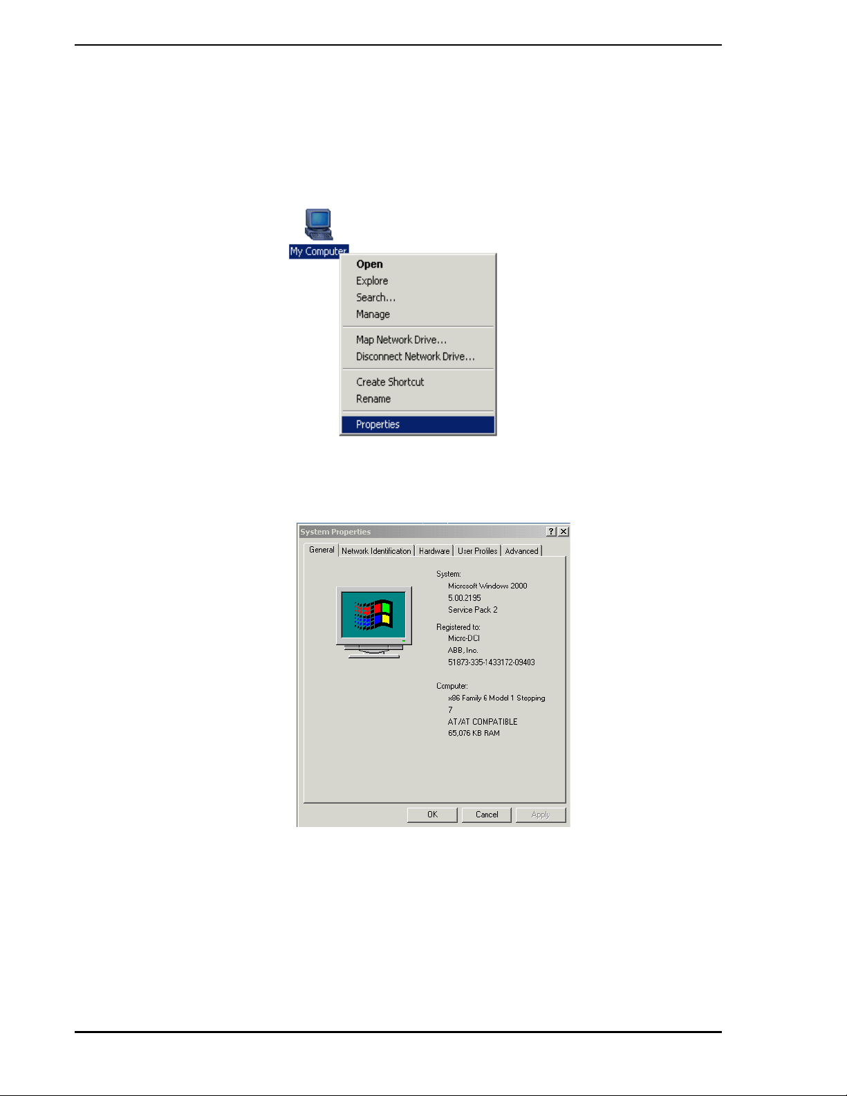
3.2.1 Verifying Windows Version
Follow these steps to determine which version of Windows is running on the PC:
• Locate the icon labeled My Computer on the Windows Desktop. With the mouse, right-click
on this icon. The drop-down menu should appear as shown below.
• From the drop-down menu, select the Properties item. The System Properties window will
appear as shown in the following figure:
• If the General tab is not selected, select it. The operating system version appears as shown in
the above figure. Verify that Windows Windows 2000 Professional Workstation or Windows
XP Professional Workstation software is installed.
14 Installation
Page 25

Micro-PWC™ Installation & Setup Guide
3.3 Determine I/O Address for Supervisor Board
Part of the Micro-PWC system installation procedure includes determining which I/O addresses have
already been assigned to other devices and function s and what I/O addre sses are ava ilable. Th is information will be necessary for installing a Supervisor Board. When installing a Supervisor Board, the I/O
address on this card must be set before it is installed. For this reason, you need to know what I/O
addresses are available when you are installing this board. Valid Supervisor Board I/O addresses are:
0x280, 0x290, 0x300, 0x310, 0x380, 0x390 and 0x3A0.
3.3.1 Windows 2000 Professional
1. Right-click on the My Computer icon on the Windows desktop. The following drop-down
menu will appear:
2. Select Manage > System Tools > System Information > Hardware Resour ces.
3. From the Computer Management dialog that appears, click I/O. The first set of four digits in
the Address column, as shown below, contains the physical I/O addresses that have already
been assigned to another function.
4. Find an unused I/O address for each Supervisor Board in the system. Valid Supervisor Board
I/O addresses are: 0x280, 0x290, 0x300, 0x310, 0x380, 0x390 and 0x3A0.
Figure 3-1. I/O Address List on Windows, Windows 2000 Professional
Installation 15
Page 26

Micro-PWC™ Installation & Setup Guide
3.3.2 Windows XP Professional
1. Locate the My Computer icon and right-click on it.
2. Select Manage > System Tools > Device Manager.
3. On the Device Manager window menu bar, select View > Resources by type.
4. Click on the Input/Output (IO) option. The I/O addresses for the PC will be listed. The first set
of four digits in the Address column contains the physical I/O addresses that have already
been assigned to another function.
Figure 3-2. I/O Address List on Windows XP Professional
5. Find an unused I/O address for each Supervisor Board in the system. Valid Supervisor Board
I/O addresses are: 0x280, 0x290, 0x300, 0x310, 0x380, 0x390 and 0x3A0.
16 Installation
Page 27

Micro-PWC™ Installation & Setup Guide
3.4 Hardware Installation
3.4.1 Supervisor Board Installation
The Supervisor board for the ISA bus is an optional Micro-DCI network communication printed circuit
board. The Supervisor board provides the software products running on PC with the ability to communicate with the Micro-DCI Networks. (If your Micro-PWC system is not equipped with Supervisor boards, you
may skip to Section 3.4.2.)
✎ NOTE One full-size ISA bus slot must be available for each Supervisor
board installed in the personal computer on which the Micro-PWC
system software will be used. An additional half-size ISA bus slot is
required immediately to the right of each Microlink Supervisor board
for which a redundant network connection is required.
3.4.1.1 Mechanical Specification
The Supervisor board is a rectangular board measuring 12.3 inches by 3.9 inches.
3.4.1.2 Electrical Specification
Power Requirements:
Component Requirement
Volt age 5 V dc =/- 5%
Current 1.5 Amps
3.4.1.3 Environmental Specification
Temperature: 0 to +60 degrees C (board only)
The temperature specification of the personal computer is a function of other product component tempera-
ture specifications (if lower) and internal temperature gradients.
3.4.1.4 Jumper Settings
The Supervisor board has three jumpers (J3, J4 and J5) that set the I/O- Port address fo r the board. Th ese
are set at the factory for I/O address 300H. Figure 3-3 shows the jumper settings that provide alternate
addressing if required, possibly for multiple board installations. Using the boa rd 's jumper s, se lect a uniq ue
I/O address for each Supervisor Board in the system based on the results of activities performed for
Section 3.3, Determine I/O Address for Supervisor Board.
To change the I/O address set by these three jumpers, remove the plastic "shorting block" from the two
undesired jumper pins and slide it over the pins th at create the desired I/O address for this supervisor
board. You can change the settings on one, two, or all three jumpers.
Installation 17
Page 28

Micro-PWC™ Installation & Setup Guide
Figure 3-3. Jumper Settings, Supervisor Board
J3 J4 J5 Base Address
AB AB AB 300H
AB AB BC 310H
AB BC AB 380H
AB BC BC 390H
BC AB AB 3A0H
BC AB BC 280H
BC BC AB 290H
3.4.1.5 Inserting the Supervisor Board
This sub-section details the steps needed to insert the Supervisor board in the expansion slot of the personal computer on which the Micro-PWC system software will be installed.
✎ NOTE The internal configuration of personal computers can vary between
models and between manufacturers. If you have questions about
the internal layout of your PC, or difficulty in following the steps
below, refer to the documentation that came with your computer.
∆ WARNING
The Supervisor board will be installed in a computer which
operates with possibly lethal voltages. Before removing the
computer cover, observe the precautions shown in
Step 1
below, to provide personal protection and prevent damage to
the systems components.
18 Installation
Page 29

Micro-PWC™ Installation & Setup Guide
1. Prepare to install the Supervisor boa rd as follows.
a. Turn off the computer and unplug the unit from its power source.
b. Disconnect all cables that are connected to the main system unit.
c. Remove any jewelry fr om you r ha nd s an d wr is ts.
d. Use only insulated or non-conductive tools.
2. Remove the computer's cover.
3. Choose an expansion slot. This can be any ISA slot that can accommodate a full length ISA
board.
4. Remove the expansion slot's backplate by removing the screw found at the top of the
backplate. Retain this screw for use in a later step.
5. Install the Supervisor board into the expansion slot. Do not touch the gold fingers on the
connector edge when handling the Supervisor board. Make sure that the board is firmly seated
in the connector slot.
6. Secure the Supervisor board to the computer chassis, using the scr ew retained in step 4. The
attachment is made at the top of the expansion slot.
7. Make sure that no components on the motherboard (e.g., heat sinks) interfere with the
Supervisor board when it is fully inserted in the motherboard card slot.
8. Replace the computer's cover.
9. Reconnect all devices and cables.
10. Turn the computer power on.
Testing the correctness of the Supervisor board installation can be performed af ter the Supervisor driver
and related software are installed. Supervisor software installation is discussed in Section 3.2, Verifying/
Installing the Windows Workstation Software.
3.4.2 Installing the Ethernet Board(s)
Before installing the Micro-PWC system software , one or mo re Ether ne t ne twork in terface boar ds must be
installed. These Ethernet network boards enable the base PC to be wired to an Ethernet network.
To install the Ethernet network board(s), see the installation instructions that are provided with each
Ethernet network board.
3.4.3 Installing the Ethernet Drivers and Related Software
Once the Ethernet network interface board(s) are installed, the drivers and related software for these
board(s) must be installed. The drivers enable the base PC to recognize that the Ethernet network
board(s) have been installed.
To install the drivers and related software for the Ethernet network board(s), see the installation instructions provided with the software for the network board(s) . See your Ethernet networ k administra tor for the
correct address for these Ethernet network board(s).
3.4.4 TCP/IP Verification/Installation
The Micro-PWC system requires the TCP/IP network interface software to be installed on the base PC.
TCP/IP software enables the base PC to communicate with other PCs over a network.
To check to see if the TCP/IP software has already been installed on the base PC, and to install the TCP/
IP software, if necessary , follow the step s below. The figures illustrating this procedure were captured on a
Micro-PWC with a Windows 2000 Professional operating system installed. The procedure is equally valid
Installation 19
Page 30

Micro-PWC™ Installation & Setup Guide
on a Micro-PWC with Windows XP Professional installed, despite slight differences in the appearance of
the windows.
1. Right-click on the My Network Places desktop icon and select the Properties menu item from
the drop-down menu that appears (Figure 3-4).
Figure 3-4. My Network Places Icon and Menu
2. In the resulting window, select Local Area Connection (see Figure 3-5).
3. Select Internet Protocol (TCP/IP) (see Figure 3-5).
20 Installation
Figure 3-5. Configuring the IP Address, Steps 2 and 3
Page 31

Micro-PWC™ Installation & Setup Guide
4. Click on the Properties button on the Local Area Connection Properties window (Figure 3-5).
The Internet Protocol (TCP/IP) Properties window is displayed (Figure 3-6).
Figure 3-6. Internet Protocol (TCP/IP) Properties
5. When installing the TCP/IP Protocols, configure the IP address and subnet mask as follows:
a. IP Address: If this PC is connected to a network, you must obtain the IP add ress from your
network administrator. If this PC is not connected to a network, it will not matter what IP
address is entered, as long as it is a number between 1 and 255.
b. Subnet Mask: Enter 255.0.0.0 as the subnet mask.
Installation 21
Page 32

Micro-PWC™ Installation & Setup Guide
3.4.5 Installing the Hardware Key
The Micro-PWC system software is licensed by MicroMod Automation Inc. The license is protected by a
hardware key . Th e hardware key is available in two versions: choose one for u se on a parallel por t, or on a
USB port. The parallel port version of the hardware key is shown in Figure 3-7.
The hardware key does not functionally compromise the port it resides on. When installed, the hardware
key provides a female connector allowing a parallel device to be attached to it. If a device (for example, a
printer) is already connected to the port, remove the cable connector from the port, connect the hardware
key to the port, and reconnect the cable to the hardware key. Signals to and from the attached device will
be passed through the hardware key. The hardware key must be installed for the Micro-PWC system software to run.
Figure 3-7. Hardware Key for Use with Micro-PWC System Software (Parallel Port Version)
Installation of Micro-PWC system software and licenses (Section 4.1.3) can proceed if the hardware key is
not attached; however, no Micro-PWC system windows can be opened. In this case, Micro-PWC™
Network Service Startup (Section 4.1.4) will not occur; instead, a pop-up window will be displayed which
states:
Can't read hardware key.
Key must be attached to port.
If the wrong hardware key is attached to the port, a pop-up window will display the following message:
No valid Micro-PWC software license found.
If problems reading the hardware key persist, test the operation of the port. This can be done by attaching
a printer to the port and attempting to print to it.
3.4.6 Connecting Micro-DCI Instruments to the Base PC
The connection necessary for this communication can be made in one of several ways:
• The computer's COM port can be connected directly to the mini-DIN configuration port on the
front of the controller as described in Section 3.4.6.1.
• A COM port on the computer can be connected to a Datalink network using a special Interface
Terminal Board (ITB) that converts the RS-232 signals used by the computer's COM port to
the RS-485 signals used by the Datalink instruments. This scheme is described in Sub-
Section 3.4.6.2.
• If the computer contains Datalink SUPERVISOR cards, each card can be connected to a
22 Installation
Page 33

Micro-PWC™ Installation & Setup Guide
Datalink network.
• If the computer contains Microlink SUPERVISOR cards, each card can be connected to a
Microlink peer-to-peer network. If each standard Microlink SUPER VISOR card is p aired with a
Redundant Microlink SUPERVISOR card, the computer can communicate with one or two
redundant Microlink networks.
3.4.6.1 Connecting to a Single 53MC5 00 0 Con trolle r
To connect a COM port on the compute r to a single 53MC5000 all you need are:
• an available COM port on the computer
• a cable to connect the COM port with the mini-DIN configuration port on the front of the
controller (behind the flip-down door below the display).
An appropriate cable is P/N 698B184U01. Six feet (1.8 m) in length, the cable has a DIN
connector on one end and a 9-pin connector on the other.
If your COM port requires a 25-pin connector, use one of these two options:
• buy an adapter locally to use the 9-pin cable
• order cable P/N 698B183U01; it has a 25-pin connector instead of a 9-pin
3.4.6.2 Connecting a COM Port to a Datalink
A COM port on the computer can be connected to a Datalink network using a special Interface Terminal
Board (ITB) (P/N 686B720U01) that converts the RS-232 signals used by the computer's COM port to the
RS-485 signals used by the Datalink instruments.
This connection scheme is illustrated in Figure 3-8. Note that this drawing shows how to connect the special RS-232/RS-485 ITB to the first 53MC5000 on the Datalink (both standard rear terminal block and
optional cord set rear connection are shown). For details concerning the rest of the Datalink (which is
essentially a "daisy chain" of instruments), its termination, and suitable wire, consult the installation section
of the 53MC5000 instruction bulletin.Note that Figure 3-8 shows a cable used to connect the ITB with a
53MC5000 having the cord set option. This cable is available in many lengths; the part numbers are
shown in Table 7-4.
3.4.6.3 Connecting the Micro-PWC System to the Datalink Network
Once a Datalink SUPERVISOR card is installed in the computer, connect the computer to the Datalink
network.
If your controllers have standard rear terminal connections, making this connection requires only one
cable. This cable has a 10-pin connector with a grounding lug on one end and five bare wires on the other.
Cables may be ordered using the part numbers shown in Table 2 in Figure 3-9.
Making this connection if your controllers are equipped for optional rear cord sets requires:
• A cable from Table 2 in Figure 3-9.
• The Communications ITB 686B622U01.
• A modular cable 677B943Uxx; this cable has a modular telephone connector on each end.
(See Table 1 in Figure 3-9 for part numbers and available cable lengths.)
To make the connection:
1. Plug the 10-pin connector on the cable to the port at the top of the SUPERVISOR card.
2. Connect the grounding lug on the connector end of the cable to the same ground as the
datalink instruments' power common.
Installation 23
Page 34

Micro-PWC™ Installation & Setup Guide
3. The bare wire end of the 677B907 cable can be connected to the st andard rear terminal
connector on the first instrument on the Datalink as shown in Figure 3-9.
If your controllers use optional cord sets, connect the bare wire end of the 677B907 cable to the terminals
on the communication ITB. Remove the resistors on the ITB as shown in Figure 3-9, then connect a
677B943 modular cable to J2 on the ITB and to J10 on the first instrument in the Datalink, as shown in
Figure 3-9.
3.4.6.4 Connecting the Micro-PWC System to the Microlink Network
Once a Microlink SUPERVISOR card is installed in the computer on which you will run the 53PW6000 software, connect the computer to the Microlink network. Making this connection requires:
• one modular cable to connect the Microlink SUPERVISOR card to the Communications ITB.
Cable 677B943Uxx can be ordered in several lengths as shown in Table 1 in Figure 3-10.
• one communications ITB (Interconnection Terminal Board) P/N 686B622U01.
• one modular cable is required to connect the Communication ITB to the fir st instrument on th e
Microlink network. Cable 677B943Uxx can be ordered in several lengths as shown in Table 1
in Figure 3.5 .
To make the connection:
1. Plug one end of the 2.5 ft (.76 m) modular cable into the port at the to p of the M ic rolink
SUPERVISOR card.
2. Plug the other end of the same modular cable into J3 on the Commun ications ITB. Le ave the
resistors on the ITB. The purpose of this ITB is to serve as a termination for the network.
3. Plug one end of the modular cable (P/N 677B943) in J1 on the ITB.
4. Plug the other end of this modular cable into J6 o n the fir st co ntro ller on the Microlink network.
If you are using a Redundant Microlink, continue with the following steps.
5. Plug the second 2.5 ft (.76 m) modular cable p rovided with the Redundant Microlink option into
the connector on the Redundant Microlink Supervisor card.
6. Plug the other end of the same modular cable into J3 on the second Communication ITB
provided. Leave the resistors on this ITB, also.
7. Plug one end of the second modular cable (P/N 677B943) in J1 on the second ITB.
8. Plug the other end of this modular cable into J8 of the first controller on the Microlink network.
24 Installation
Page 35

Micro-PWC™ Installation & Setup Guide
Figure 3-8. Connecting the Computer’s COM Port to the Datalink
Installation 25
Page 36

Micro-PWC™ Installation & Setup Guide
26 Installation
Figure 3-9. 53SU6000Datalink SUPERVISOR Card to
Datalink Interconnection Diagram (ID-53-1610)
Page 37

Micro-PWC™ Installation & Setup Guide
Figure 3-10. 53SU6000 Microlink SUPERVISOR Card to Microlink
Interconnection Diagram (ID-53-1597)
Installation 27
Page 38

Micro-PWC™ Installation & Setup Guide
3.4.7 Verifying System Configuration
The Micro-PWC system is a powerful system and has specific system requirements. Before installing the
Micro-PWC system, proper configuration of the base PC and the Ethernet network must be verified.
3.4.7.1 Verifying Version, Processor Type and Memory Amount
3.4.7.1.1 Windows 2000 Professional
Right-click on the My Computer icon on the Windows 2000 desktop and select Properties from the dropdown menu:
Select System Summary from the Computer Management dialog that displays.
28 Installation
Page 39

Micro-PWC™ Installation & Setup Guide
3.4.7.2 Verify Display Configuration
To determine the number of colors and resolution configuration on your Windows-based PC, navigate to
the Control Panel and click on Display.
Click on the Settings tab to display the following window:
The following Windows configuration options should be used to ensure proper Micro-PWC system oper ation:
• Color Palette - The minimum number of colors required by the Micro-PWC system software is
256. The recommended number is 65536 or higher (this will prevent unnecessary color remapping when switching between Micro-PWC system application windows and
non-Micro-PWC system application windows).
• Font Size - The Small Fonts font size is recommended.
• Desktop Area - The minimum and recommended desktop area size is 1024x768 pixels,
although a higher resolution can be used.
3.4.7.3 Verify Configuration of Printer Spool Options
Print spool options must be properly configured so that the Micro-PWC system device manager will not
lock up if there is a problem with the printer. You can configure the print spool options as follows:
For each printer that will be used by the Micro-PWC system print manager, you must configure the print
spool option by specifying the Job Prints While Spooling option.
To verify that this option has been selected, navigate to the Control Panel and select Printers. Then for
each printer to be used by the Micro-PWC system print manager, select the File > Properties menu
sequence, select the Scheduling tab, and then select the Start Printing Immediately option.
Installation 29
Page 40

Micro-PWC™ Installation & Setup Guide
3.4.7.4 Verify Configuration of Tasking Option
The TASKING/PERFORMANCE option is used to determine the relative responsiveness of PC and server
applications that are running at the same time. You can configure the tasking option as follows:
To access configuration of this option::
1. Navigate to the Control Panel.
2. Click on the System icon.
3. In the resulting System Properties window, click on the Advanced tab.
Depending on your type of Windows operating system, proceed as described in Section 3.4.7.4.1 or Sec-
tion 3.4.7.4.2. The setting described in the appropriate sub-section is the only setting which will ensure
proper processing of background (server) applications.
To achieve the best results, the Performance option should be configured, as described in Section
3.4.7.4.1 or Section 3.4.7.4.2, prior to installation of the Micro-PWC system software. If necessary, this
setting will be adjusted to the correct value by the Micro-PWC system software after it is installed.
3.4.7.4.1 Setting the Performance Option in Windows XP
1. In Windows XP, In the Performance pane of the Advanced tab, click on the Settings button.
2. In the Performance Options window, click on the Advanced tab.
3. in the Processor Schedulng pane, select the Background Services option.
3.4.7.4.2 Setting the Performance Option in Windows 2000
1. In Windows 2000, on the Advanced tab, click on the Performance Optimization button.
2. In the Performance Options window, select the Background Services option.
3.4.7.5 Verify Configuration of Desktop Options
Two of the Desktop/Display options can affect the performance of the Micro-PWC system:
•the Dragging option
•the Screen Saver option
To access configuration of these options:
1. Navigate to the Control Panel.
2. Click on the Display icon.
These options may be correctly configured as described in Section 3.4.7.5.1 through Section 3.4.7.5.3.
3.4.7.5.1 Setting the Dragging Option in Windows XP
1. In the Display Properties window, select the Appearance tab.
2. Click on the Effects button
3. In the
Effects window, locate the checkbox labelled Show window contents while dragging.
4. Verify that the small checkbox for this item does not have a check in it.
3.4.7.5.2 Setting the Dragging Option in Windows 2000
1. In the Display Properties window, select the Effects tab.
30 Installation
Page 41

Micro-PWC™ Installation & Setup Guide
2. In the Visual Effects pane, locate the checkbox labelled Show window contents while
dragging.
3. Verify that the small checkbox for this item does not have a check in it.
3.4.7.5.3 Setting the Screen Saver Option
To configure the Screen Saver option, navigate to the Control Panel and select Display.
Click on the Screen Saver tab. Certain screen saver programs (mainly the OpenGl-based screen saver
programs) can cause serious degradation of the Windows server performance. For this reason, use of the
Blank screen saver option (Windows XP) or no screen saver (the [None] option on Windows 2000) is
strongly recommended. Certain other screen savers may yield acceptable performance (e.g., Starfield
Simulation).
✎ NOTE To achieve the best results, the Drag mode and Screen Saver
settings should be configured as described here prior to installation
of the Micro-PWC system software. If necessary, this setting will be
adjusted to the desired value by the Micro-PWC system software
after it is installed.
3.4.7.6 Verify Taskbar Options
The Windows T askbar is typically displayed at the bottom of the screen. However, the Micro-PWC operator
windows also typically extend to the bottom of the screen. To make it ea sier to view and resize the operator
windows, change the Taskbar settings as follows:
•Select Start > Settings > Taskbar & Start Menu.
• Next, select both the Always on top and the Auto Hide options. (In Windows XP, these options
are labelled Keep the Taskbar on top of other win dows an d Au to hide th e taskbar.) With these
options, the taskbar is hidden (allowing the operator windows to be fully visible) until the
mouse is moved to the very bottom of the screen.
3.4.7.7 Verify Power Management Options
Some PC's support power management at the BIOS level, independent of the operating system. When th is
power management feature is enabled, it will power-down various components of the computer after a
period of user inactivity.
Power management may shut-down the hard drive, the network card, and even the CPU, causing the
Micro-PWC software to halt. Since the b ackground M icro- PWC t asks providing ser vices such as comm unication and data collection should continue to run even if the us er is not act i ve ly usin g the k ey bo ard or
mouse, all power management features should be disabled. To disable BIOS level power management, refer to the documentation for your computer.
3.5 Installing the Micro-PWC Software
Now you will begin the process of installing the Micro-PWC software. The Micro-PWC system can be
installed in two modes: the Micro-PWC mode or the Micro-PWC Client mode. You will select which mode
you want to install at the beginning of the installation process. A description of the two modes follows:
Micro-PWC Mode - Select this mode when you want to install the Micro-PWC software to operate with a
full complement of servers and fully participate in network operations (e.g., synchronize network-wide files,
include database and graphics files, etc.). A Micro-PWC node can act as a server node for other nodes
running Micro-PWC Client software. A "srvr" license is required to use this mode.
Installation 31
Page 42

Micro-PWC™ Installation & Setup Guide
Micro-PWC Client Mode - When this mode is selected, the system provides operator displays, but does
not perform network tasks such as database and graphics storage and communication with other consoles. These tasks are performed by a separate node which then provides the information to the client
nodes which it serves. The server node must be operational prior to the startup of Client systems. A "client" license is required to use this mode.
Table 3-1. License Type and Operational Mode Interaction
LICENSE TYPE
srvr X X
client X
If you are installing the Micro-PWC software in the Micro-PWC mode, go to Section 3.5.1, Micro-PWC
Mode Installation, and begin the installation process. If you are installing the Micro-PWC softwa re in the
Micro-PWC Client mode, go to Section 3.5.2 and begin the installation process.
OPERATIONAL MODES ENABLED
Micro-PWC Micro-PWC Client
3.5.1 Micro-PWC Mode Installation
3.5.1.1 Pre-Setup Procedure
• Check that the Micro-PWC hardware key is connected to the parallel port of the computer.
• Have the license key(s) ready.
• Have the Micro-DCI Supervisor board I/O port address(es) ready.
• Power on the base PC and boot the Windows operating system software.
• Log on to the Windows software with administrative privileges. You must have administrative
privileges or the installations process will not complete successfully.
• Close all Windows applications that are open, (such as Microsoft Word, Excel, Mail,
Scheduler, etc.).
✎ NOTE Micro-PWC Setup is the main installation program. Several sub-
windows will open and close throughout the installation process.
The installation will be complete when the main Micro-PWC Setup
program ends. Do not reboot the base PC until the main MicroPWC Setup prompts you to do so.
3.5.1.2 Beginning Micro-DCI Master Setup for Full Micro-PWC Operation
✎ NOTE For Micro-PWC client installation, skip to Section 3.5.2.
1. Insert the Micro-DCI CD into the CD-ROM drive.
2. Open Windows Explorer and select the drive letter of the CD-ROM drive.
3. In the root directory of the CD-ROM, double click on the setup.exe file.
4. In the Micro-DCI Master Setup, click on the Install Micro-PWC button.
3.5.1.3 Beginning Micro-PWC Installation
• The InstallShield Wizard is loaded and then the Micro-PWC System Setup window appears.
32 Installation
Page 43

Make sure all other Windows applications are closed on your PC.
• Click Next to begin installing the Micro-PWC system.
3.5.1.4 Micro-PWC Setup
•The Install Micro-PWC window appears and asks whether or not to install the Micro-PWC
portion of the Micro-PWC product now. The Setup program just scanned your system for any
existing versions of the Micro-PWC software and informed you of the results of this scan
through the text in this window. The following instructions assume that a previous version was
not found. If a previous version was found, simply follow the instructions in the Setup
program.
•Select Install Micro-PWC now to begin installing the Micro-PWC software on your base PC.
• Click the Next button.
• An informational dialog box appears advising yo u that the the Micro-PWC so ftware inst allation
will launch in a separate window.
• Click the Ok button.
3.5.1.5 The SETUP Window
• A setup window appears. Then the Micro-PWC window appears.
Micro-PWC™ Installation & Setup Guide
• To continue, click the Next button.
• The Operational Mode window appears. Select Micro-PWC or Micro-PWC client mode.
Click the ? button at any time for help.
• Click the Next button.
• In the Node Identification window that appears, enter a number be tween 1 and 99 in the Enter
node number field. If you have more the one Micro-PWC system on this Ethernet, you must
make sure the number you enter is a unique number.
• In the Enter node group number field, enter a number between 1 and 50.
• Click the Next button.
•The Server Settings window appears. In the Maximum number of clients for this node
field, enter a number between 0 and 10.
• Click the Next button.
• In the Installation Directory window that appears, enter the full path where you want the
Micro-PWC system files to be installed. The default installation drive and directory is
C:\MICROPWC. If you want to change this path, enter both the drive and directory/directories
you want to use as the installation directory for the Micro-PWC system files.
• Click the Next button.
• If the directory you entered does not yet exist, a Question window will appear asking if you
want this directory created. If this window appears, click the Yes button.
3.5.1.6 Copying Micro-PWC Files
•The Micro-PWC Setup program then begins to extract and install the Micro-PWC system files
to the path you specified. In the Extracting/Installing files window, the progress bar moves
from 0% to 100% as the files are installed. Wait until all files are installed (100%) before
proceeding.
• An information window appears informing you that Setup will now install the required servers,
Installation 33
Page 44

create the Micro-PWC folder and create the capuser account.
3.5.1.7 Installation Options
• The Installation Options window appears. Make sure the Start Micro-PWC Network Level
services automatically box is highlighted.
• Make sure the Start Micro-PWC display automatically box is not highlighted.
• Make sure the Use Desktop Colors box is highlighted.
• Make sure the Font Size box to the left of Medium is highlighted. You can click one of the ?
buttons at any time for help.
• Click the Next button.
• A message window appears informing you that the Micro-PWC software is now installed on
your system (in full Micro-PWC mode). To activate this program, you must have the hardware
key plugged into the parallel port on the base PC and enter the proper license keys when
prompted. Click the Ok button.
• The Setup sub-window will close and return back to the main Installing Micro-PWC Setup
window.
Micro-PWC™ Installation & Setup Guide
3.5.1.8 Installing Micro-PWC License Keys
• An information window appears stating that Setup will now start the Micro-PWC Maintenance
Utility where all of the Micro-PWC systen license keys will be entered.
• An Information window appears explaining on how to use the Micro-PWC Maintenance utility.
• The License Features window appears. Click the Add button at the bottom of the window.
•The Add New Feature window appears. In the Feature text entry fie ld, type Micro-PWC. This
field is not case sensitive.
• Make sure that the information in the Version field, Expiration Date field, and Number of Users
field is correct. If not, enter the correct information.
• In the License field, enter your 20-digit Micro-PWC system license key. Do not enter any
spaces when you enter this license key. This field is not case sensitive.
• Click the Ok button.
• Add additional license keys, as necessary for your Micro-PWC system.
• After all license keys have been added, click the License Admin item on the toolbar a nd select
Save.
• Then click on the License Admi n item on the toolbar and select Exit. This sub-window closes
and returns you to the main Setup window.
3.5.1.9 Choosing Location for the Micro-DCI Portion of Micro-PWC System
•The Choose Destination L ocation window appear s, which enables you to specify the drive a nd
directory where you want the Micro-DCI Communica tio ns Servic es portio n of th e Mic ro -PW C
system installed. The drive and path you select does not impact the location of the MicroPWC files you just installed earlier in the installation process. You can accept the default path
by clicking the Next button or you can change the destination directory by clicking the Browse
button.
• If you clicked the Browse button, enter both the drive and directory you want to use as the
destination directory in the Choose Directory field.
34 Installation
Page 45

Micro-PWC™ Installation & Setup Guide
• If the directory does not exist, the Setup program will ask you if it should be created. If this
window appears, click the Yes button.
• Click the Next button.
•The Select Program Folder window appears. Select the program Folder you want the Micro-
PWC program icons added to. The Micro-PWC folder is selected by default as the folder for
the program icons. You can accept the d efault, select an existing progra m folder , or type a new
program folder.
• Click the Next button.
•A Setup window with a progress bar appears and the Micro-DCI files begin to install.
•The Enter Information window appears and prompts you to enter an eight-character name for
your entire Micro-DCI local system.
• Enter a unique name for your Micro-DCI system and click the Next button.
• The progress bar finishes updating and the Setup process continues.
3.5.1.10 New Program Group/Program Folder
• The Micro-PWC Setup program then creates the Micro-PWC System program folder and
automatically adds the appropriate icons for the Micro-PWC product.
• If you are upgrading or reinstalling a Micro-PWC system over an existing Micro-PWC system,
a window will appear at this time asking if you would like to add any networks (Micro-DCI
instruments) now. If you would like to add Micro-DCI instrument networks, click on the Yes
button.
3.5.1.11 Adding Micro-DCI Networks
• The Add Micro-DCI Networks window appears. Click the Next button.
• The Setup program then starts the Super32 program, which is a Micro-PWC program that
enables you to add Micro-DCI network instrument s to your system. This is a good time to add
Micro-DCI networks to your system, since you need to reboot your PC after installing the
Micro-PWC software and after you install the Micro-DCI networks.
• The first Network Wizard window lets you select whether you are adding a network that is
connected to your system through a supervisor board (SUP) or though a COM port (COM).
Select either SUP or COM. Then click the Next button.
• In the Network Wizard - Network Attributes window, enter a Network Name (up to 15
characters) and select a Network Position. Then click the Next button.
•The Network Wizard - Backup window appears. Select Master or Backup, and then click the
Next button.
•The Network Wizard - Network Parameters window appears. Set the I/O Port Address to
agree with the address jumpers on the Supervisor board as shown in Figure 3-3. The
parameters change depending on the type of network that is being installed.
• After selecting the port, click the Next button.
• In the Network Wizard - Finish window, click the Finish button.
• A window appears stating that you need to reboot your computer for the system to recognize
the newly added SUP Micro-DCI networks. Click the Ok
button.
• If the network was added successfully, Super32 will ask if another network is to be added. If
so, repeat the above steps until all desired Micro -DCI network s have bee n a dded. An swer ing
No exits Super 32 and returns you to the Main Micro-PWC Setup program.
Installation 35
Page 46

Micro-PWC™ Installation & Setup Guide
• At this point the Notepad application opens and a Micro-PWC Read Me file appears,
containing Micro-PWC release information. When you have finished reading this document,
close Notepad.
• Setup will now ask if you want to restart the PC.
•Select Yes and then click the Ok button to restart the PC.
• This completes the setup process. Proceed to Section 3.5.3.
3.5.2 Micro-PWC Client Installation Mode
3.5.2.1 Pre-Setup Procedure
• Check that the Micro-PWC hardware key is connected to the computer.
• Have the client license key(s) ready.
• Power on the base PC and boot the Windows operating system software.
• Log on to the Windows software with administrative privileges. You must have administrative
privileges or the installations process will not complete successfully.
• Close all Windows applications that are open, (such as Microsoft Word, Excel, Mail,
Scheduler, etc.).
✎ NOTE Micro-PWC Setup is the main installation program. Several sub-
windows will open and close throughout the installation process.
The installation will be complete when the main Micro-PWC Setup
program ends. Do not reboot the base PC until the main MicroPWC Setup prompts you to do so.
3.5.2.2 Beginning Micro-DCI Master Setup
• Insert the Micro-DCI CD into the CD-ROM drive.
• Open Windows Explorer and select the drive letter of the CD-ROM drive.
• In the root directory of the CD-ROM, double click on the setup.exe file.
• In the Micro-DCI Master Setup window, click on the Install Micro-PWC button.
3.5.2.3 Beginning Micro-PWC Installation
•The InstallShield Wizard is loaded and then the Micro-PWC System Setup window appears.
Make sure all other Windows programs are clos ed on this PC.
• Click Next to begin installing the Micro-PWC system.
3.5.2.4 Micro-PWC Setup
•The Install Micro-PWC window appears and asks whether or not to install the Micro-PWC
portion of the Micro-PWC product now. The Setup program just scanned your system for any
existing versions of Micro-PWC and informed you of the results of this scan through the text in
this window. The following instructions assume that a previous version was not found. If a
previous version was found, simply follow the instructions in the Setup program.
•Select Install Micro-PWC now to begin installing Micro-PWC on your base PC.
• Click the Next button.
• An informational dialog box appears advising you that the Micro- PWC installation will launch in
36 Installation
Page 47

a separate window.
• Click the Ok button.
3.5.2.5 The SETUP Window
• A setup window appears. Then the Micro-PWC pop-up window appears.
• To continue click the Next button.
•The Operational Mode window appears. Select Micro-PWC Client mode. Click the ? button at
any time for help.
• Click the Next button.
• In the window that appears, enter a number between 1 and 99 in th e Enter node number field.
If you have more the one Micro-PWC system on this Ethernet, you must make sure the
number you enter is a unique number.
• In the Enter node group number field, enter a number between 1 and 50.
• Click the Next button.
•The Client Settings window appears. Click on the Search button to request that the Setup
program search for available servers and create a list of these servers.
• A list of available servers appear in the Available Servers window. From the list of servers,
select the server you want to designate as the Primary Server and click on the Primary button.
Then select the server(s) you want to designate as the secondary server(s) and click the
Secondary button. You can click the ? button at any time for Help.
Micro-PWC™ Installation & Setup Guide
• After selecting the primary and secondary servers, click the Close button to continue.
• Click the Next button.
• In the Installation Directory window that appears, enter the full path where you want the
Micro-PWC system files to be installed. The default installation drive and directory is
C:\MICROPWC. If you want to change this path, enter both the drive and directory/directories
you want to use as the installation directory for the Micro-PWC system files.
• Click the Next button.
• If the directory you entered does not yet exist, a Question window will appear asking if you
want this directory created. If this window appears, click the Yes button.
3.5.2.6 Copying Micro-PWC Files
• The Micro-PWC Setup program then begins to extract and install the Micro-PWC system files
to the path you specified. In the Extracting/Installing files window, the progress bar moves
from 0% to 100% as the files are installed. Wait until all files are installed (100%) before
proceeding. .
• An information window appears informing you that Setup will now install the required servers,
create the Micro-PWC folder and create the capuser account.
3.5.2.7 Installation Options
•The Installation Options window appears. Make sure the Start Micro-PWC display
automatically
box is not highlighted.
• Make sure the Use Desktop Colors box is highlighted.
• Make sure the Font Size box to the left of Medium is highlighted. Y ou can click the ? button at
any time for help.
Installation 37
Page 48

Micro-PWC™ Installation & Setup Guide
• Click the Next button.
• A message window appears informing you that Micro-PWC is now inst alled on your system (in
Micro-PWC Client mode). To activate this program, you mu st have the har dware key plugge d
into the PC and enter the proper license keys when prompted. Click the Ok button.
•The Setup sub-window will close and return back to the main Installing Micro-PWC Setup
window.
3.5.2.8 Installing Micro-PWC Client License Key
• An information window appears saying Setup will now start the Micro-PWC Maintenance
Utility where the Micro-client License Key will be entered.
•An Information dialog appears with information on how to use the Micro-PWC Maintenance
utility.
•The License Features window appears. Click the Add button at the bo ttom of the window.
•The Add New Feature window appears. In the Feature text entry field, type Microclient
with no spaces in this word. This field is not case sensitive.
• Make sure that the information in the Version field, Expiration Date field, and Number of Users
field is correct. If not, enter the correct information.
• In the License field, enter your 20-digit Microclient license key. Do not enter any sp aces when
you enter this license key. This field is not case sensitive.
• Click the Ok button.
• After the license key has been added, click the License Admin item on the toolbar and select
Save.
• Click on the License Admin item on the toolbar and select Exit. This sub-window closes and
returns you to the main Setup window.
3.5.2.9 Select a Program Folder
•The Select Program Folder window appears. Select the Program Folder you want the
Micro-PWC program icons added to. The Micro-PWC folder is se lected by default as the folder
for the program icons. You can accept the default, select an existing program folder, or type a
new program folder.
•An Information window appears advising you to delete a program group after the in stallation is
complete.
• Click the Ok button.
•The Micro-PWC Setup program then creates the Micro-PWC System program folder and
automatically adds the appropriate icons for the Micro-PWC product.
• Setup will now ask if you want to restart the PC.
•Select Yes and then click the
Ok button to restart the PC.
3.5.3 Microsoft Excel Installation Requirements
Use the installation instructions supplied by the manufacturer to install Micr osof t Excel for Windows on the
PC on which the Micro-PWC system software is loaded.
After Microsoft Excel has been installed, the PATH environment variable must be updated to include the
path of the Microsoft Excel executable program. This path may be included as follows:
1. Navigate to the Control Panel and select System.
38 Installation
Page 49

Micro-PWC™ Installation & Setup Guide
2. In the System Properties window that appears, click on the Environment tab.
3. In the System Variables field, scroll down to the PATH variable and select it. The PATH
variable and its associated value will be displayed in text entry boxes (labeled Variable and
Value) at the bottom of the window.
4. In the Value text entry box, edit the value to include the path of the Excel Executable. Typically
this means adding one of the following directories to this PATH: \msoffice\excel or
\excel. Be sure to include the drive specification as well as the directory (e.g.,
c:\microsoft\excel).
3.5.3.1 Add-in Functions for Microsoft Excel
A number of special functions, sometimes referred to as "add-ins", have been developed to provide the
Micro-PWC system interface to Microsoft Excel.
The add-in functions are contained in the file FPEXCEL.XLA. This file is located in the bin directory for the
Micro-PWC system software; i.e., <installation directory>\bin. Typically, this is:
C:\MICROPWC\BIN
In order to make the add-in functions available to Excel, perform the following operations:
1. Start Microsoft Excel.
2. Click on the Tools item on the menu bar of the Excel spreadsheet, then click on
Add-Ins... on the resulting menu. The Add-Ins dialog box will appear.
3. In the Add-Ins dialog box, click on the Browse... button, which will cause the Browse dialog
box to appear.
4. The Browse dialog box contains two scrollable list boxes labelled File Name and Directories.
In the Directories list box, locate the entry for the bin directory of the Micro-PWC system
installation. Click on this entry to select it.
5. In the File Name list box, the file name FPEXCEL.XLA will appear. Click on FPEXCEL.XLA to
select it, then click on the Ok button. This will exit the Browse window and return to the
Add-Ins window.
6. A list box labelled Add-Ins Available is located in the Add-Ins window. Locate the entry which
reads Fpexcel. Click in the square next to this item to select it, then click on the Ok button.
The function will now be available for use.
Once installed, the add-in functions can be accessed using either of the following methods:
1. Click on a cell to select it, then type in the function.
2. Alternatively, use the Function Wizard for Excel. In the Function Wizard, the add-in functions
can be found under the User Defined Function category. (To access the Excel Function
Wizard, select the sequence Insert > Function from the menu bar of the Excel spreadsheet.
See your Microsoft Excel documentation if you have questions about the Function Wizard for
Excel.)
3.5.3.2 Printing Microsoft Excel Spreadsheets
Printing and scheduling of Excel spreadsheets through the Micro-PWC system is supported, provided that
a valid printer name is selected for use. A valid printer name is one that was configur ed using the Windows
Printer utility. Valid printer names for use with Excel spreadsheets may be determined as follows:
Navigate to the Control Panel and select Printers. Printers that have been configured in Windows appear
in a list format or as icons in this window. When attempting to print o r schedule printing of a n Excel spreadsheet, be sure to use one of the printer names found in this list. (Information on how to initiate log printing
Installation 39
Page 50

Micro-PWC™ Installation & Setup Guide
and scheduling can be found in the Micro-PWC Configuration Guide and the Micro-PWC Operator's
Manual.
Printing can also be performed using the standard Microsoft Excel print option.
40 Installation
Page 51

Micro-PWC™ Installation & Setup Guide
4.0 START-UP and OPERATION
4.1 Micro-PWC Startup
4.1.1 Startup Options
Micro-PWC system startup behavior is determined by the options selected during Micro-PWC system
installation. (To view or change the startup options, select Setup from the Micro-PWC system program
group.)
If the Start Micro-PWC Displays Automatically option was selected, then each time the Windows software
is restarted, the user named capuser is automatically logged in, and the Micro-PWC system windows (the
System Window, Process Alarm Window and Operator Window[s]) are automatically opened. (See Section
4.3, The Capuser Account, for details on the capuser account.)
If the Start Micro-PWC Displays Automatically option was not selected, then the Micro-PWC system displays can be started by logging in to the Windows software with an administrator account other than
capuser, and selecting Start > Programs > MicroMod Autom ation > Micro-PWC > System Window to start
the Micro-PWC system displays.
✎ NOTE The Micro-PWC system software can only be run if you are logged
into a Windows user account which belongs to the Administrators
group. If you log into an account which is not a member of the
Administrators group, an error dialog box containing the following
message will appear whenever you try to open a Micro-PWC
system window:
Unable to communicate to the service manager
Both the capuser account and the administrator account belong to the Administrators group.
4.1.2 Micro-PWC Program Group
When Micro-PWC system setup is complete, the following Windows Program Group is created:
Figure 4-1. Micro-PWC Program Group
Start-up and Operation 41
Page 52

Micro-PWC™ Installation & Setup Guide
The function of some of the icons contained in the Micro-PWC™ Program Group are detailed below:
Double-click on the Read Me icon for important information about this
software release.
If the Start Micro-PWC Displays Automatically option was not selected
during Setup, double-click on the System Window icon to start the Micro-
PWC system. For more information, see the Micro-PWC
Super32 is the Micro-DCI network administration program used to configure
networks, instruments, tags, etc. Double-click this icon to start Super32. For
more information, see the Micro-PWC
The Micro-DCI DDE Server provides data in "tag.atom" format to DDE clients
such as Microsoft Excel.
™
Configuration Guide.
™
Operator's Manual.
Double-click on the Graphics Editor icon to create custom graphics. For
more detailed information, see the appropriate section in the Micro-PWC
Configuration Guide.
Double-click on the Micro-PWC Maintenance icon to add or edit license
keys. See Section 6.0, MAINTENANCE, for more information.
Double-clicking on the Setup icon allows modification to the Micro-PWC
parameters established during the installation process. May be used to
change the START PWC DISPLAYS AUTOMATICALLY setting, font size,
etc.
Double-clicking on the Documents icon shows the available Micro-DCI
instruction manuals.
™
42 Start-up and Operation
Page 53

Micro-PWC™ Installation & Setup Guide
4.1.3 Licensing During Initial Startup
License information must be entered during the first startup of the Micro-PWC system after installation.
The initial startup will proceed more quickly if you locate this information first and have it available for reference. The license information consists of a list of features on one or more lice nse forms which are shipped
with Micro-PWC system product. The license form contains the following for each licensed feature: a feature name, a version number, an expiration date, a number of users, a license key, a user string, and a
machine ID.
When the first Micro-PWC system window is opened, a window containing the following message will
appear:
No valid Micro-PWC software license found.
Do you want to enter license information now?
Click on Yes, and a window titled Micro-PWC Maintenance Utility will appear. Click on the Add button in
this window, and a pop-up window titled Add New Feature will appear.
Locate the drop-down combo box labelled Feature in the Add New Feature window. (A drop-down combo
box consists of a text entry box and drop-down pushbutton; clicking on the pushbutton provides access to
a drop-down list box of selections.)
Click on the drop-down pushbutton, then click on the Micro-DCI item in the drop-down list to select it. The
only value which you must enter for the Micro-DCI feature is the 20 character license key. The license key
is not case sensitive. All of the other values for the Micro-DCI feature are predefined. After enterin g the
license key, click on Ok. If you entered the license information correctly, the pop-up window will close and
the information will be added to the list in the main window. If the information has not been entered correctly, an error message will appear.
The machine ID for the Micro-DCI feature must match the number of the hardware key attached to the PC.
This value should appear in the box labelled Machine ID when you first open the Add New Feature window. The machine ID can also be displa yed by se lecting on Li cense Admin > Show Machine/Host ID from
the menu bar. If the machine ID is not displayed, then the hardware key may not be attached, or the hardware key driver is not available (which will happen if the PC has not been restarted since the Micro-PWC
system software was installed).
After entering the Micro-DCI license, use the same procedure to enter keys for any optional features you
may have.
After you have completed entering license information, select License Admin > Exit from the menu bar. A
confirmation window will be displayed; click on Yes in this window. If you entered a valid license for the
Micro-DCI feature, the Micro-PWC system startup will proceed.
To change or add license information at a later time, you can select the Micro-PWC Maintenance Utility
from the Micro-PWC menu item.
4.1.4 Micro-PWC Network Service Startup
All of the Micro-PWC system windows make use of the Micro-PWC system network service for communication, database access, and other su pport. If yo u open a Micro -PWC system windo w and the Micro-PWC
system network service is not yet running, it will be started, and a window titled Micro-PWC Network
Startup will appear. A counter in this window will update each second while the Micro-PWC system network service starts. The time required for the network service to startup can vary widely, depending on the
number of other Micro-PWC system nodes on the network and the amount of configuration information to
be synchronized between them. The progress of the startup can be monitored by clicking on the Log button, and periodically clicking on the Refresh button in the resulting pop-up window.
The Exit button in the Micro-PWC Network S t artup window will close the window , but it does not cancel the
Micro-PWC system network service startup.
Start-up and Operation 43
Page 54

Micro-PWC™ Installation & Setup Guide
When the startup of the Micro-PWC system network services is complete, the Micro-PWC Network S t artup
window will close, and the Micro-PWC window that you opened will appear. If this is the System Window,
then the Process Alarm Window and Operator Window will also appear.
4.2 Stopping the Micro-PWC Software
The display portion of the Micro-PWC system software can be stopped by closing all of the Micro-PWC
system windows. This means the user interface is shutdown, while the the network service level continues
to operate. (The network service level of the software provides such functions as communication with the
instruments, data collection, and so on.) Alternatively, the Micro-PWC system software can be completely
shutdown by stopping both the display functions and the network service. Shutting down both the display
portion and the network service level in effect removes the Micro-PWC system from the network.
4.2.1 Closing the Micro-PWC System Windows
The Micro-PWC system windows can be closed from the System Window; select Menu > User > Exit. The
System Window Exit Options window will be displayed. In this window, click on the toggle button labelled
Close System Window and Other Micro-PWC Windows. Click on Ok to complete the operation.
4.2.2 Stopping the Micro-PWC System Network Serv ice
The Micro-PWC system network service will continue to run after all Micro-PWC system windows are
closed, and after you have logged off from Windows. (This allows process data to be collected and stored
even when no Micro-PWC system windows are open.) The Micro-PWC system Network Service can be
stopped in either of these two ways:
• To stop the Micro-PWC system Network Service and close all Micro-PWC system windows,
select Menu > User > Exit from the System Window. The System Window Exit Options window
will be displayed. In this window, click on the toggle button labelled Full Micro-PWC
Shutdown - Close All Micro-PWC Windows and S top Micro-PWC Network Le vel. Click on
Ok to complete the operation. This is the preferred method of stopping the Micro-PWC
Network Service. It cannot be used from the capuser account, however (described in Section
4.3). Login to the Windows operating system as Administrator to use this option.
- or -
• The Micro-PWC Network Service can be also stopped from the Windows Control Panel. This
may be done as follows:
Select Start > Settings > Control Panel > Services. In the Services window, select
Micro-PWC Network Level from the list of services, and then click the Stop button.
44 Start-up and Operation
Page 55

Micro-PWC™ Installation & Setup Guide
4.3 The Capuser Account
During installation of the Micro-PWC system softwa re, a Windows user account named capuser is created.
This is intended to be used as a "captive" account for plant operators, dedicated to running the Micro-PWC
system display applications.
✎ NOTE The Micro-PWC system software doesn't have to be run from the
capuser account; it can be run from any Windows user account
which belongs to the Windows Administrators group.
The important features of the capuser account are listed below.
1. Display startup: When you log on using the capuser account, the Micro-PWC system display
applications are started. The System Window, Process Alarm Window, and one or more
Operator Windows are opened. (There may be a delay while the Micro-PWC system network
service is started.)
The very first time you log on using the capuser account, some configuration changes are
automatically made to the account. A pop-up window with the following message appears:
Completed setup of capuser account.
Logging off now to save setup.
2. Taskbar: After logging on to the capuser account, the Taskbar is not displayed so that only
Micro-PWC system applications can be run.
✎ NOTE With the proper Micro-PWC system access level, a user can go to
the System Window and select Menu > Utilities > Other
Applications to restart the Taskbar.
3. Autologon: If the Start Micro-PWC Displays Automatically option was selected during MicroPWC system installation, the capuser account will automatically be logged on during system
startup. This is implemented using the Windows autologon feature.
Logoff from the capuser account is accomplished by selecting Menu > User > Exit item from
the System Window. Logoff can also be performed by pressing the <C
keys simultaneously, and then clicking on the Logoff button. Note that if the autologon feature
is enabled, the capuser account will immediately be logged on again.
The autologon feature can be disabled in either of two ways:
a. Hold the S
prompts for username and password) will eventually be displayed. At this point you can
log in using any Windows user account.
b. Alternatively, you can select Setup from the Micro-PWC program group, then de-select
the Start Micro-PWC Displays Automatically installation option.
After a user other than capuser has logged on to Windows (for example, if you log on as
administrator), the autologon feature is disabled. To re-enable it, you must logon as capuser
again, or you must again select the S t art Micro-PWC Displays Automatically installation option
from the Micro-PWC Setup program.
HIFT key down during logoff, and the normal Windows logon window (which
TRL>+<ALT>+<DELETE>
4. Password: The default password for the capuser account is passwd. If you want to change the
password, select the Setup program from the Micro-PWC program group, and click the
Password button on the Installation Options window.
Start-up and Operation 45
Page 56

Micro-PWC™ Installation & Setup Guide
4.4 Re-installing the Micro-PWC Software
If the Micro-PWC system software has already been installed, and you wish to re-install it, use the following procedure.
1. If necessary, backup your Micro-PWC system configuration using the Micro-PWC Backup/
Restore utility. (The Backup/Restore utility is accessed by selecting Menu > Utilities from the
System Window.)
2. Archive any historical data that you need to keep. (The Archive Database utility is accessed by
selecting Menu > Utililties from the System Window.
3. Install the Micro-PWC system software as described in Section 3.5 of this Guide.
4.5 Removing a Micro-PWC Installation
If necessary , the Mi cro-PWC system sof tware and r elated data can be completely removed from the PC on
which it is installed. To do so:
1. Navigate to the Control Panel.
2. Select Add or Remove Programs.
3. In the Add or Remove Programs window, locate the entry for Micro-DCI Micro-PWC.
4. Click Remove. Doing so will completely remove the following:
•all Micro-PWC system software
•the Micro-PWC system program group
•the capuser account
•all Micro-PWC system configuration data
•all data in the Historical Database
✎ NOTE This utility should NOT be used if you are re-installing or
upgrading the Micro-PWC system software.
46 Start-up and Operation
Page 57

Micro-PWC™ Installation & Setup Guide
4.6 Network Time, Time Zones, and Time Adjustment
All timestamps in the Micro-DCI system are stored in Greenwich Mean T ime (GMT), an d then converted to
the local time for display to the user. Conversion from GMT to local time on a particular computer is controlled by the computer's time zone setting and Daylight Saving Time setting.
4.6.1 Verifying Consistent Network GMT
✎ NOTE Many Micro-DCI operations are performed on a network-wide
basis. It is very important that all nodes on the network have the
same notion of the current GMT.
THE FACT THAT ALL NODES ON THE NETWORK DISPLAY THE
SAME TIME DOES NOT MEAN THA T THEIR GMT TIME VALUES
ARE IDENTICAL!
Different time zone and Daylight Saving Time settings could be
masking different GMT values.
The following procedure can be used to verify that all Micro-DCI node s have the same GMT value, and the
same time zone and Daylight Saving Time settings:
1. On all nodes, compare the current time displayed in the Micro -PWC System Window. It should
be the same on all nodes.
2. From the Micro-PWC System Window, select Menu > Configure > Message Configuration.
3. Enter a test message and click on the Send button.
4. The message and its time stamp will be displayed on the bottom line of the Process Alarm
Window. (If the message and timestamp do not appear, check your filtering configuration.)
5. Compare the time stamp in the Process Alarm Window on all nodes; it should be the same.
If the comparison performed in Step 1 or Step 5 fails, then either the GMT is not consistent across all
nodes, or the time zone and Daylight Saving Time settings are not consistent, or both.
4.6.2 Time Settings
4.6.2.1 Changing the Time Zone Setting
You can change the time zone, time, and, if necessary, date, for the Micro-PWC system as follows:
1. From the System Window, select Start > Settings > Control Panel > Date/Time.
2. In the Date/Time window, click on the Time Zone tab.
3. Click on the drop-down arrow for the Time Zone box to select the correct time zone.
4. After changing the time zone, click on the Date & Time tab and use the text entry box to enter
the correct value for the local time.
✎ NOTE When you select a different time zone, Windows does not recompute the
local time value. You MUST adjust the local time to the correct value after
changing the time zone and before clicking Ok in this window. If you change
only the time zone and click Ok, the GMT will be changed to match the date
and time currently displayed in the Date/Time window. (It is typically only
necessary to change the hour, although the date may need to be changed,
too, depending on the time of day at which you are making the change.)
Start-up and Operation 47
Page 58

Micro-PWC™ Installation & Setup Guide
4.6.2.2 Daylight Saving Time
The Daylight Saving Time adjustment is also controlled from the Date/Time window discussed in Section
4.6.2.1. If the Automatically Adjust for Daylight Saving Time option in the Date/Time window is selected,
the US Daylight Saving Time rule (first Sunday in April to last Sunday in October) will be used when converting GMT to local time.
This rule may not be correct in all time zones. If there is a difference in the rule governing Daylight Saving
Time at your location, DO NOT change the local time on the Micro-PWC system (this would change the
GMT and violate the rule of the common GMT). Instead, on the first da y of Daylig ht Saving Time, manually
select the button labelled Automatically Adjust for Daylight Saving Time. De-select this item on the first day
after Daylight Saving T ime ends.
4.6.3 Time Adjustment
All Micro-PWC system applications assume a monotonical (always increasing) GMT time value. Manual
adjustments to the local Micro-PWC system time can violate this assumption, and can also de-synchronize
the network time. For these reasons, the Micro-PWC Time Adjustment feature should always be used
when the time needs to be adjusted.
Figure 4-2. Time Adjustment Window
If time adjustment is needed, use this procedure:
1. Shut down all nodes except for one.
2. Stop the Micro-PWC system applications and servers on this node.
3. Change the time setting. Use the U
the desired number of seconds to adjust the time. If you are setting the time back, wait an
interval at least equivalent to the value of the adjustment before proceeding. (For example, if
you are setting the time back 5 minutes, wait 5 minutes before proceeding.)
4. Restart the node and verify that the time is correct.
5. Start the other nodes on the network.
48 Start-up and Operation
P or DOWN arrows to the right of the Adjustment box to select
Page 59

Micro-PWC™ Installation & Setup Guide
4.7 Naming Conventions
TAG.ATOM Notation
All Micro-PWC applications use the TAG.ATOM naming convention to reference da ta valu es. The TAG portion of the name uniquely identifies the module containing the value. The ATOM portion uniquely identifies
which of the values in the module is to be referenced.
4.7.1 TAGs
4.7.1.1 Types of TAGs
There are three types of TAGnames:
USER-CONFIGURED: User-configured TAGnames are Micro-DCI "A" values in the
instrument. See the respective instrument's Instruction Bulletin to see
if the module of interest has been assigned a TAGname. The
TAGname may be configured using any configuration method
available for the instrument in question, e.g., front panel, hand-held
unit, or the super32 configuration program.
EXTENDED: Extended TAGnames are generated for 53SL6 000 controllers. Since
the controller only has a single "A" value (the Unit Tagname),
additional TAGnames are created by adding suffixes to the Unit
Tagname.
NETWORK ADDRESS: The System Module of all instruments can be referenced by Network
Address TAGnames of the form "Netname-ia", where Netname is the
name assigned to the Micro-DCI network and "ia" is the network
address of the instrument (0-31).
4.7.1.2 Special Considerations in Us in g TAGnames
Any unused modules in instruments should have their Tagname set to null. The easiest way to do this is to
use the Remove Tag function in the Super32 software package (descr ibed in the 53PW6000 Micro-PWC
Configuration Guide).
The Micro-PWC system does not allow the use of duplicat e tagnam es . The first occurrence of a tag is
used. Super32 recognizes duplicate tagnames and attaches a suffix to the end of duplicate tags to make
them unique.
Although Micro-DCI instruments can store any ASCII character in a tagname, the Micro-PWC system only
recognizes A-Z, 0-9, _ (underscore) and - (dash). All unrecognized characters will be scanned-in as underscores.
Start-up and Operation 49
Page 60

Micro-PWC™ Installation & Setup Guide
4.7.2 ATOMS
4.7.2.1 Types of ATOMnames
There are two types of ATOMnames:
SYMBOLIC
ATOMNAMES:
NETWORK
ATOMNAMES:
Symbolic A TOMnames are short abbreviations for the nam e of the
value; for example, PV for Process Variable,etc. Available
ATOMnames are listed in the "Micro-DCI Instrument ATOM
Reference" portion of the Micro-DCI on-line Help.
Network ATOMnames (called "Network Reference" in the
53SL6000 Instruction Bulletin) have the form L00, C101, etc.
4.8 Other Considerations
The UdciGDS.ini file (located in the Windows root directory) allows several parameters of the MicroPWC system to be customized:
[Events]
Area This parameter should be set to the a rea in which all Micro-DCI
events will be reported.
Values range from 1 to 64.
Priority This parameter should be set to the priority level at which all
Micro-DCI events will be reported.
Values range from 1 to 16.
[Timing]
AtomStaleSec The Micro-PWC system's Micro-DCI instrument interface
provides values to the various Micro-PWC system displays.
This parameter establishes an upper limit as to how old trend
data values may be. Setting this parameter to low time values
produces fresher data but increases the time requir ed to call up
a display for the first time. Settings are in seconds. Values
range from 1 to 65535 seconds.
BkgdDelayMSec This parameter is set by the factory and should not be
changed.
50 Start-up and Operation
Page 61

Micro-PWC™ Installation & Setup Guide
5.0 TROUBLE-SHOOTING
5.1 General Recommendations
The Micro-PWC is primarily a software product which is installed in the user's Personal Computer. This
means the environment in which the Micro-PWC components are installed can be very site-specific.
Table 5-1 provides general information and cross references to aid in the resolution of problems arising
during installation and setup of Micro-PWC components. If the source of the problem is external to MicroPWC hardware and software (e.g., in Windows, in a third-party Ethernet interface board or driver, etc.),
consult the appropriate documen tation.
Table 5-1. Micro-PWC Installation and Setup Problems and Recommendations
SYMPTOM RECOMMENDATION
No power, LEDs not lit. Make sure power cable is properly connected.
Make sure that the power switches on the personal com puter unit a nd the
monitor are in the ON position.
Micro-PWC software not
running.
Not communicating on the
Ethernet Network.
Make sure the Hardware Key is properly installed on the parallel port. The
hardware key is used to license the Micro-PWC software, and must
be installed for the Micro-PWC software to run. See Section 3.4.5 for
information on installing the Hardware Key.
Make sure the Micro-PWC software has been properly installed. See
Section 3.5 for information on installing the Micro-PWC software.
Make sure that the Micro-DCI license has been properly installed.
Installation of the Micro-DCI license is discussed in Section 4.1.2.
Make sure the Ethernet interface board is properly installed.
Make sure the driver and other software for the Ethernet interface boa rd is
properly installed. See Section 3.4.3 for details on network interface
software installation.
Make sure the IP address and subnet mask for the Ethernet interface
board are properly configured. See Section 3.4.4 for details on
configuration of these items.
If an Ethernet interface board is installed, consult the docu me n tation tha t
came with the board to determine what diagnostic procedures are
available for the board.
Trouble-shooting 51
Page 62

Micro-PWC™ Installation & Setup Guide
5.2 Diagnostic Messages
Diagnostic output on the Micro-PWC falls into several categories:
• Messages generated by the Windows operating system
• Messages generated by the Micro-PWC system software
5.2.1 Windows Messages
Messages generated by the Windows operating system can be viewed using the Event Viewer from the
Administrative T ools program group. See the documen tation which accompanied yo ur Windows software
for further details on use of this item.
5.2.2 Micro-PWC System Diagnostic Output
Diagnostic output from Micro-PWC system server programs and applications is stored in the SYSLOG and
SYSLOG.OLD files. For details on this utility, see Section 6.1.1 of this Guide.
5.3 Technical Support
Technical support for the Micro-PWC™ product is available from the manufacturer. Cont act your local sales
office for information on obtaining technical sup port. See also the READ FIRST section at the beginnin g of
this Guide.
52 Trouble-shooting
Page 63

Micro-PWC™ Installation & Setup Guide
6.0 MAINTENANCE
The Micro-PWC system software includes a system administration utility called Micro-PWC Maintenance.
This utility provides a user-friendly interface to Micro-PWC system maintenance operations and administrative functions. You can access Micro-PWC Maintenance as follows:
Select Start > Programs > Micro-PWC > Micro-PWC Maintenance.
Once the Maintenance utility is started, the Micro-PWC Maintenance Utility window will be displayed. This
window has three items available from the menu bar:
•Basic
• String Files
• License Admin.
Each of these menu items provides access to a pull-down menu.
The remainder of the window is blank when the window is first displayed. The contents of this part of the
window will vary, depending on which menu item is selected. This chapter describes the maintenance utilities and administrative functions available from the Micro-PWC Maintenance Utility window.
6.1 The Basic Menu
The Basic item on the Micro-PWC Maintenance Utility window provides access to the following menu
items:
• Display Log File
• Set System Language
• Exit
6.1.1 The Display Log File Menu Item
Diagnostic output from Micro-PWC system server programs and applications is stored in a system log file
named SYSLOG. As messages are generated, they are appended to the bottom of the file. When
SYSLOG reaches approximately 100 KB, the contents are move d to a file called SYSLOG.OLD, and the pr evious contents of SYSLOG.OLD are discarded. This prevent s the system log files from consuming too much
disk space.
The data in these files can be helpful in identifying problem s if the Micro-PWC system software does not
start correctly, or is not functioning correctly.
Select Basic > Display Log File to view the SYSLOG and SYSLOG.OLD files. When the Display Log File
item is clicked on, the main portion of the Micro-PWC Maintenance Utility window will display the SYSLOG
file in a scrollable list box. Use the radio buttons at the top of the list box to toggle between SYSLOG and
SYSLOG.OLD.
The SYSLOG display does not update dynamically. To view messages which have been generated since
the SYSLOG file was opened for viewing, click on the SYSLOG toggle button. This causes the SYSLOG file
to be re-read. To view the newest entries in the file, click on the Bottom button.
If you want to search for a particular string, enter that string in the Find text entry box and click on the Find
button. The line containing the desired string will be displayed in the list box. The arrow button at the end of
the text entry box determines the direction (up or down in the file) of the search.
Maintenance 53
Page 64

Micro-PWC™ Installation & Setup Guide
6.1.2 The Set System Language Menu Item
By default, English is the language used for the text found on Micro-PWC system windows, menus, buttons, and so on. The labels, titles and other words used in this ma nner ar e calle d strings. Users who wish
to customize their system and translate text strings into languages other than English can create new
directories of string files for the desired languages(s). The English language strings in these files are then
translated into the new language. When this task is completed, the Micro-PWC system must be instructed
to use the directory for the new language instead of the ENGLISH directory. (Creation of new string files
and string file directories is discussed in Section 6.2.)
To change the language directory used, select Basic > Set System Language. The Select Language window will be displayed. Click on the desired entry (for example, German), then click on Ok. Any windows
opened after this operation has been completed will be displayed in the new language. Windows which
were already opened will remain in the original language; close them, then re-open them, to use the new
language.
✎ NOTE The Micro-PWC system setup program always sets the system
language directory to be ENGLISH during the Micro-PWC system
installation.
6.1.3 Exit
Select Basic > Exit to exit the Micro-PWC Maintenance Utility program. If you were editing an item su ch as
a string file, you will be prompted to save the changes before exiting.
6.2 The String Files Menu
The String Files item on the menu bar of the Micro-PWC Maintenance Utility window is used to access the
utilities used to create new language directories and to create, modify and verify string files. The String
Files menu includes the following utilities:
• Open
•Save
• Create Language Directory
• Verify Language Directory
• Update Language Directory
• Delete Language Directory
6.2.1 Modify a Language String File
The Open item is used to modify a language string file. Click on this menu item to display the Load File
window. Toggle button s in this window allow you to select the desired language directory (for example,
English, German, French). After the language directory has been selected, a list box will display the
available string files in that directory . Click on a file to select it, then click on Ok. The text of the selected file
will then be opened for edit (using the Micro-PWC system note editor) in the main portion of the Micro-
PWC Maintenance Utility window.
The file will contain comment lines (lines beginning with the '#' character), which provide information about
the file. Below the comment lines are string file entry lines, which consist of a symbolic name, followed by a
string value in quotes. For example:
SI_LOGIN "LOGIN NAME: "
54 Maintenance
Page 65

Micro-PWC™ Installation & Setup Guide
The symbolic name is the name used in the Micro-PWC system software. The quoted string is the actual
string that appears in various Micro-PWC system configuration and operator windows. The following rules
must be observed when modifying a language string file:
• Only the characters within the quotation marks should be edited. No other portion of
the file should be touched.
• Do not change the order of the entries.
• Do not add or remove quotation marks.
• Do not add or remove lines. (Blank lines may be inserted.)
• Formatting characters such as "%s" and "%d" should not be modified, deleted, re-
ordered or added.
Changes to a string file are not made permanent until the file is saved using the Save option under the
String Files menu (Section 6.2.2).
✎ NOTE The string files in the English language directory cannot be
modified.
6.2.2 Save Changes to a Language String File
When modifying a string file using the Open menu item, current changes to the string file are made using
the Save item on the String Files menu.
During the Save operation, the syntax of the file will be checked, ensuring that the symbolic names and the
quoted strings are correctly paired together. If errors are encountered, information about the errors will be
displayed in a pop-up window; line numbers of the lines in error will be included in the error descriptions.
6.2.3 Create a Language Directory
To create a new string file language directory, select String Files > Create Language Directory. A pop-up
window appears which contains a text entry box and prompts you to enter the name of the new language
directory to be created. A new language subdirectory with this name will be created.
Once the directory is created, the default English string files are automatically copied to this directory, and
verified. The quoted strings in these files can then be translated into the desired language using the Open
command.
6.2.4 Verify a Language Directory
Once changes have been made to string files, they must be compiled and verified before the changes t ake
effect. Normally these actions are performed automatically by the SAVE operation. To verify a language
directory manually, select the sequence String Files > Verify Language Directory. All the files in this lan-
guage directory will be compiled and verified.
When the operation is complete, a Verify Language Directory window will be displayed. At least one line
per string file is included in the list displayed in this window. If no errors are found for a file, the line states
only that the file was verified. If errors are found, a description of the error(s) and the number(s) of the
line(s) containing the error(s) will be included in the list.
6.2.5 Update a Language Directory
When a new Micro-PWC system software release is installed on an existing Micro-PWC system, the new
release may contain entries that are added or changed since the previous release. If user-created lan-
Maintenance 55
Page 66

Micro-PWC™ Installation & Setup Guide
guage directories have been created, they must be updated to reflect the new or changed items.
✎ NOTE Before the new Micro-PWC system software is installed, the
existing user-created language directories should be backed up
using the Backup/Restore utility described in the Micro-PWC
Operator's Manual. After the new Micro-PWC system software has
been installed, use the same utility to restore the user-created
language directories to the Micro-PWC system.
Use the Update Language Directory item on the String Files menu to determine what string file entries
have been added or changed since the last release, that need to be translated.
When a user-created language directory is made, a reference copy of the English version of each string
file is created on the Micro-PWC system. (These reference copies are not normally available to the user.)
When the Update Language Directory utility is run, the versions of the language string file (in the English
language directory) are compared with the reference copies (in the use r-created language directory). The
comparison will yield one of the following results:
• If an entry is compared and no differences are found, the entry in the language string file is
preserved.
• If an entry is in the new English file but not in the old, an entry is added to the user-created
language string file containing the translations. This entry is preceded by the following
comment line:
"# TRANSLATION REQUIRED"
• If an entry does not compare, the "# TRANSLATION REQUIRED" comment line is added, as
well as an additional comment line that includes both the old entry in the language string file,
and the new English file entry.
• If the entry is in the old English reference file, but not in the new English string file, the entry in
the user-created language string is removed.
Once the comparisons for all files are complete, a pop-up window is displayed which lists the files in the
user-created language directory wh ich requir e ed itin g (i.e ., contain the “ # TRANSLATION REQUIRED”
comment lines).
6.2.6 Delete a Language Directory
To delete a user -created language di rectory, select the sequen ce S tring Files > Delete Lan guage Directory.
A pop-up window will be displayed. This window contains a list of user-created language directories which
can be deleted.
To delete a language directory, click on the desired directory in the list, then click the Ok button. A confirmation box will be displayed which asks:
Click Yes to complete the delete operation; the language directory will be deleted and you will be returned
to the Micro-PWC Maintenance Utility window. Click on No to exit without deleting the language directory.
✎ NOTE The English directory is not included in this list. This is the
Micro-PWC system default language directory, and cannot be delete d.
? Delete Language Directory
56 Maintenance
Page 67

Micro-PWC™ Installation & Setup Guide
6.3 The License Administration Menu
6.3.1 Accessing the License Administration Utilities
The Open item on the License Admin. menu is used to add, modify, and delete license keys. When this
item is selected, the main portion of the Micro-PWC Maintenance Utility window will contain a list of the
currently licensed features for the Micro-PWC system. Function buttons in this window are used to Add
new licensed features, and to Modify and Delete licensed features in the list. Changes made will not be
permanent until the license data is saved using the Save item (Section 6.3.1.4) on the License Admin.
menu.
To add a new licensed feature, click on the Add button to display the Add New Feature window. This window contains a combo box labelled Feature, and the following text entry boxes:
•Version
• Expiration Date
• Number of Users
• License Key
•User String
• Machine ID
6.3.1.1 Add a Licensed Feature
Enter the Feature name, License Key and User String data for the feature; the Version, Expiration Date,
Number of Users and Machine ID will be displayed automatically. Click on the Apply button to enter the
information and leave the window open to add additional new features, or click on Ok to add the currently
configured feature information and close the Add New Feature window.
When either the Apply or Ok buttons are clicked on, a license verification will occur. If any text fields contain incorrect data, an error pop-up window will be displayed, the feature will not be added to the list, and
you will be returned to the Add New Feature window.
6.3.1.2 Modify Licensing of an Existing Feature
To modify the configur ation of a curr en tly licensed fe ature, clic k on an item in the list of features, then click
on the Modify button. A pop-up window very similar to the Add button window will be displayed, except
that all fields will be filled in with the selected feature's values.
When either the Apply or
tain incorrect data, an error pop-up window will be displayed, the license configuration for the feature will
not be modified, and you will be returned to the Modify Existing Feature window.
6.3.1.3 Delete a Licensed Feature To delete a licensed feature, click on an entry in the list of features, then click the Delete button.
Ok buttons are clicked on, a license verification will occur. If any text fields con-
6.3.1.4 Save Licensing Data for Licensed Features
The Save item on the License Admin. menu is used to save the licensed features that were edited using
the Open item on the License Admin. menu.
Maintenance 57
Page 68

Micro-PWC™ Installation & Setup Guide
6.3.2 Show Machine/Host ID
The machine/host ID number contained in the hardware key is used to uniquely identify each Personal
Work Center. To view this number, select License Admin. > Show Machine/Host ID. The machine/host ID
number will be displayed in a pop-up window. This number also appears in the Machine ID text field in the
Add New Feature and Modify Existing Feature windows.
58 Maintenance
Page 69

Micro-PWC™ Installation & Setup Guide
7.0 SUPPORT SERVICES
A number of support services are available to users of the Micro-PWC system and other Micro-DCI software and equipment. These include training programs, software maintenance agreements, and replacement parts.
7.1 Software Maintenance Agreement
A Software Maintenance Agreement provides the user with Software Update Service. Software Updates
may provide modifications, improvements and/or enhancements to existing functionality. Software Update
Service includes:
• the right to receive one copy of the Software Update s for the software specified in the
Agreement, and related standard documentation, which are released during the term of the
Agreement.
• a copy of the standard documentation concerning Micro-DCI Software Updates.
✎NOTE Technical support and installation of Software Updates are not
included in the Software Update Service.
7.2 Training
A modern facility is available that provides service and repair instruction. On-site training is also available.
Contact a local company sales office for specific information and scheduling.
7.3 Replacement Parts
The Micro-PWC system is a software product. Optional hardware items available for use with the MicroPWC system are shown in Table 7-1 through Table 7-4.
Support Services 59
Page 70

Micro-PWC™ Installation & Setup Guide
Table 7-1. Interconnection Terminal Boards (ITB)
MODEL PART NUMBER
Datalink Card 172S001U02
Microlink Card 686B627U01
Communications 686B622U01
Table 7-2. Supervisor Cards
MODEL PART NUMBER
Datalink Card 686B574U02
Datalink Card w/PLC Option 686B574U03
Microlink Card 686B619U03
Microlink Card w/PLC Option 686B619U04
Redundant Microlink
Interface
686B626U01
Table 7-3. Firmware Upgrade Kits
MODEL PART NUMBER
Datalink Supervisor Card - To upgrade
previous revisions to Rev. 5.0
Microlink Supervisor Card - To upgrade
previous revisions to Rev. 5.0
614C085U01
614C086U01
60 Support Services
Page 71

Micro-PWC™ Installation & Setup Guide
Table 7-4. Cable Assemblies
Cable Function
Datalink Card to Micro-DCI Instrument
(screw terminals non-cord set)
Datalink Card to 53MC1000 or 50KM2000
(cord-set receptacle units)
[connector on both ends of cable]
One per instrument required
Length
Feet (Meters)
5 (1.5) 677B907U01
10 (3) 677B907U02
15 (4.6) 677B907U03
20 (6.1) 677B907U04
25 (7.6) 677B907U05
30 (9) 677B907U06
50 (15) 677B907U07
5 (1.5) 677B906U01
10 (3) 677B906U02
15 (4.6) 677B906U03
20 (6.1) 677B906U04
25 (7.6) 677B906U05
30 (9) 677B906U06
50 (15) 677B906U07
Part Number
Microlink Card to 53MC5000
Datalink Card to CCI / CCO ITB
Microlink Card to CCI / CCO ITB
2.5 (0.8) 677B943U01
5 (1.5) 677B943U02
25 (7.6) 677B943U03
40 (12) 677B943U04
50 (15) 677B943U05
75 (23) 677B943U06
100 (30.5) 677B943U07
200 (61) 677B943U08
300 (91.4) 677B943U09
400 (122) 677B943U10
500 (152) 677B943U11
6 (1.8) 677B908U01
5 (1.5) 677B944U01
10 (3) 677B944U02
25 (7.6) 677B944U03
Support Services 61
Page 72

Micro-PWC™ Installation & Setup Guide
When ordering standard p art s for the Micro- PWC system, use th e p art number s and descriptio ns shown in
Table 7-1 through Table 7-4. Order replacement parts from a local factory sales office. Provide the part
description, spare part order number and quantity.
7.4 Technical Documentation
Additional copies of this Guide can be obtained from the nearest company sales office at a reasonable
charge.
62 Support Services
Page 73

Micro-PWC™ Installation & Setup Guide
8.0 THE @aGlance/IT SERVER INTERFACE
8.1 Overview
8.1.1 General Information About @aGlance/IT
The @aGlance/IT server interface is an optional utility which provides a live data link between the MicroPWC and a variety of software applications resident on other distributed control systems, supervisory control systems, personal computers, and so on. Easy access to this plant data assist s th ose involved in such
pursuits as problem analysis and resolution, product improvement, process improve ment and resource
optimization. Obtaining process data directly from the process control system eliminates the possibility of
error induced by manual data entry. @aGlance/IT provides a clean, stan dardized interface which allows
data to be transferred between different hardware platforms while retaining its meaning, despite inherent
differences in the way dat a is formatted on dif ferent systems ( e.g., byte order, floating point formatting, and
so on).
Tools in which the user may wish to import live process data include a broad range of applications, such as
relational databases, expert systems, spreadsheets, simulation tools, r eport generators, visualization tools,
statistical analysis packages, planning tools, charting tools and graphic tools. Each class of tools (e.g.,
spreadsheets, statistical packages, and so on) has a different way of interacting with users.
In order for the exchange of data to take place, @aGlance/IT is required for each participating network
partner.
The architecture of the @aGlance/IT software is based on a client-server model. A process known as an
@aGlance/IT server typically runs on the system which "owns" the process control data (e.g., a MicroPWC system); a process known as an @aGlance/IT client typically runs on the system which will be a
"consumer" of that data (e.g., a PC or a supervisory control computer). A system can run both client and
server applications simultaneously. The optional Micro-DCI interface to @aGlance/IT is an @aGlance/IT
server available for use on Micro-PWC systems. Client software must be provided by the user.
8.1.2 The @aGlance/IT API for Micro-DCI
Any @aGlance/IT client can connect to any @aGlance/IT server, assuming the minimum re quirement s for
network transport are met to access the server running on the Micro-PWC system.
The @aGlance/IT Application Programming Interface (API) on Micro-DCI consists of:
• an @aGlance/IT server which can prov ide data to @aGlan ce /I T clien ts,
• support for @aGlance/IT methods (functions) used by:
• commercially available @aGlance/IT client applications (e.g., the @aGlance/IT Add-In for
Excel)
• users engaged in creating custom @aGlance/IT client applications
Also provided is a window-based interface for:
• identifying data structures in Micro-DCI databases (by tagname and atom)
• defining translations for the Micro-DCI atoms to other terminologies, such as the Instrument
Society of America's SP72 standard
• viewing information about servers and server activity.
The implementation of @aGlance/IT on Micro- DCI permits the access of up to 500 points per second from
either the client or server side.
@aGlance/IT Server Interface 63
Page 74

Micro-PWC™ Installation & Setup Guide
8.1.3 Micro-DCI @aGlance/IT Server Requirements - Micro-PWC Version
The following requirements must be met in order to successfully run the @aGlance/IT API server:
• TCP/IP must be installed on the node on which the @aGlance/IT server is to run .
On the Micro-PWC system, if a single channel Ethernet board is present and detected by the
Windows software during installation, the necessary TCP/IP software will be loaded
automatically. If the Ethernet board is not detected, or if a Supervisor board is present, the
TCP/IP software should be installed when it is prompted for during Windows software
installation.
• A properly installed license for the @aGlance/IT API for Micro-DCI must be present. One
Micro-DCI @aGlance/IT Server Interface license is included with each set of Micro-PWC
system software. Additional licenses can be purchased.
On the Micro-PWC system, the user is prompted to enter license keys during the initial st artup
of the system, as described in Section 4.1.3 of this Guide. After the initial startup, inst allation of
license keys is performed using the License Administration menu, described in Section 6.3.
✎ NOTE
If the license has not been installed for the Micro-DCI @aGlance/IT
server interface, it is still possible to use the @aGlance/IT
Administration Tool described in Section 8.2.1.1. It will not be
possible to start @aGlance/IT servers on the Micro-PWC system,
however.
64 @aGlance/IT Server Interface
Page 75

Micro-PWC™ Installation & Setup Guide
8.2 THE @aGlance/IT Server Operation
The @aGlance/IT API for Micro-DCI translates between the @aGlance/IT methods and data structures,
and those of the Micro-DCI Global Database.
✎ NOTE Configuration of the @aGlance/IT internal interface on the Micro-
PWC system is performed using utilities provided by Axeda
Systems Inc. It is assumed that the user has had Windows software
training and/or experience, and has an understanding of the
Windows environment. It is further assumed that users creating
custom @aGlance/IT clients are familiar with @aGlance/IT
development software and the documentation (including on-line
help) supplied by Axeda Systems Inc..
8.2.1 Configuring the @aGlance/IT Server Internal Interface
There are two aspects to @aGlance/IT server configuration: external interface configuration and internal
interface configuration. The @aGlance/IT external interface configuration is use d to identify t agnames and
attributes (atoms) in the Micro-DCI global database, and is described in the Micro-PWC Configuration
Guide.
The @aGlance/IT internal interface configuration, described here, is used to identify the nodes on which
@aGlance/IT servers will run. Servers identify themselves to @aGlance/IT at run time, and client applications specify, at run time, the names of the servers with which they wish to communicate. Internal configuration, accomplished using the @aGlance/IT Administration Tool, is required so that the server nodes can
be recognized by @aGlance/IT clients. When a client issues a r equest to communica te with a server application, @aGlance/IT will look for it on servers which have been identified using the @aGlance/IT Administration Tool.
After an @aGlance/IT server has been defined, the @aGlance/IT item available from the System Window
Menu button provides access to the external interface. The external interface provides the ability to identify
the set of tagnames and their associated attributes (atoms) which will be recognized by the @aGlance/IT
servers. It also allows you to configure translations of the attribute (atom) names, to make them recognizable to applications on other platforms.
8.2.1.1 Registering Server Nodes
To access the @aGlance/IT Administration Tool, from Windows select Start > Programs > MicroMod
Automation > Micro-PWC > @aGlance/IT Administration. The @aGlance/IT Administration Tool window
will be displayed. The main options on this window are:
• Server Hosts (server host registration)
• Proxies (client registration)
• Permissions (permission configuration)
Use the Server Hosts option to register all potential server node names in the @aGlance/IT configuration
database for the local node. Server registration iden tifies an d char acter ize s nodes which contain a server
that client applications will access. When the Server Hosts option is selected, the user interface provides a
text entry box labelled Server Host. To register a server node, enter the Internet ho st name of the server in
this text entry box.
Server registration is only necessary on nodes where a client application (e.g., Microsoft Excel) exists. All
nodes containing client applications have to register the name of the Micro-PWC system which contains
the @aGlance/IT server, in order to find and communicate with the server.
@aGlance/IT Server Interface 65
Page 76

Micro-PWC™ Installation & Setup Guide
The Micro-DCI @aGlance/IT Server communicates using TCP/IP. If you have questions about TCP/IP or
about Internet host names in use at your site, see your system administrator. If you have questions about
the options on or configuration via this display, see the on-line help text available from the Help button.
Information about client nodes and client users is configured using the Proxies option, which is described
in Section 8.3.
8.2.2 Starting a Server and Server Names
Typically, the maximum number of @aGlance/IT servers for which the node is licensed are started when
the system is started. A Server started automatically by the system will be assigned a default name in the
format:
EBi<node name>
where the i is an index number used to identify the server , and the <node name> is the name o f the node
(Micro-PWC system) on which the server is running. For example, if the node named CON4 is licensed for
two servers, two servers will be started automatically. The servers will be named EB1CON4 and EB2CON4.
A maximum of two @aGlance/IT servers can run simultaneously on a Micro-PWC system, and each of
these servers can have up to 10 simultaneous client connections.
8.2.2.1 Starting a Server with Non-Default Options
It is possible to customize parameters such as Server Name and Interval for the servers which are started
automatically on system start up. To do so, you must create a file named aagServ.dat in the directory
\PWC\data. Each line in this file is an entry that includes the options which define one server.
For example, to define two servers, named "spock" and "tuvok", each with a monitor interv al of 3 seconds,
the aagServ.dat file would consist of the following lines:
-s spock -m -i 3
-s tuvok -m -i 3
Available server start-up options are described in Table 8-1.
Table 8-1. Options for Use When Starting a Server
OPTION AND
<ARGUMENT>
-server <server name> The argument supplied with this option is the name to be used for the
@aGlance/IT server. The server name can have a maximum of 20
characters. If this option is omitted, the default server name "aagServer" will
be used. On a system licensed for the @aGlance/IT server for Micro-DCI,
the number of servers for which the system is licensed will be started
automatically when the system is booted. (The maximum number of servers
per node is 2.)
-nsessions <number> The argument (number) supplied with this option determines the maximum
number of sessions allowed for the @aGlance server. The maximum number
of sessions allowed per server is 10, which is the default used if the
-nsessions option is not specified. If an argument with a value less than 1 is
supplied with this option, the number of sessions will be set to 1. If an
argument with a value greater than 10 is supplied, the number of sessions will
be set to 10.
DESCRIPTION
66 @aGlance/IT Server Interface
Page 77

Micro-PWC™ Installation & Setup Guide
Table 8-1. Options for Use When Starting a Server (Continued)
OPTION AND
<ARGUMENT>
-interval <seconds> The argument (seconds) supplied with this option defines the number of
seconds in the poll interval. This argument is an integer; the minimum
number of seconds that can be specified is 1.
-monitor When this option is used, the monitor feature will be enabled. Monitoring
provides the means whereby an @aGlance/IT client is advised (at a default
or specified poll interval) regarding the values contained in specified data
points.
-daemon When this option is used, the server will run as a background process.
-clientshutdown When this option is used, a client which requests a server shutdown usin g the
AAG_Shutdown method will be able to shutdown the server, provided that the
session which is requesting the shutdown is the only session running.
-evtmessage Each time a client starts or ends a session, a message is displayed in the
system event display area of the Mini-Alarm Window, the Event Review
display, and is also entered into the Event Historian. The message contains
the following data in the order shown:
<Time><Date><Node Name><@aGlance Server Name>(<Micro-DCI login
name>:<Remote Host name>:<Remote User account identification>)<session ID>
When the -evtmessage option is used, these messages will be suppressed.
DESCRIPTION
✎ NOTE Clients do not need to be aware of which node the server is
running on.
@aGlance/IT Server Interface 67
Page 78

Micro-PWC™ Installation & Setup Guide
8.3 Security for the @aGlance/IT Server
The two aspects to security for the @aGlance/IT API for Micro-DCI are:
• client access to the @aGlance/IT server for Micro-DCI, and
• access to the Micro-DCI Global database
8.3.1 Security for Access to the @aGlance/IT Server for Micro-DCI
Client proxy definition is used to specify which clients are permitted to access the server applications on
the local node. A client proxy account is a mapping from a remote host name and user ID to a local ID.
Client proxies are configured on the node in which the @aGlance/IT Server for Micro-DCI is installed.
Client proxy definition is performed using the @aGlance/IT Administration Tool. (Access to the
@aGlance/IT Administration Tool is described in Section 8.2.1.1.) From the @aGlance/IT Administration
Tool, select the Proxies option.
From the user interface of the Proxies option, the following three types of client proxy accounts can be configured:
• One user on one host (a separate proxy account for a user on a remote node)
• All users on one host (a single proxy account for ALL users on a remote node)
• All users on all hosts (a single proxy account for ALL users on ALL remote nodes)
In all cases, the default proxy is called AAG.
The simplest procedure is to set up a single account for all users on all remote nodes. To use the default
proxy (AAG), configure a Micro-DCI user named AAG, using the user login configuration as described in
Section 2 of the Micro-PWC Configuration Guide. The desired access level and area permissions should
be configured for the user named AAG.
Client proxy definition is a function of the @aGlance/IT Administration Tool provided by Axeda Systems
Inc.; it does not contain provisions for passwords on client proxy accounts. Security is based on the
@aGlance/IT server for Micro-DCI matching the remote node and user names with the local proxy configuration at runtime.
See the @aGlance/IT on-line help subsystem for information on client proxies and how to configure them.
8.3.2 Security for Micro-DCI Database Access
Database access security for the @aGlance/IT Server for Micro-DCI is based on the access level and area
permissions configured on the remote node for the user running the @aGlance/IT client software. The
access level and area permissions correspond to the local user name specified in the @aGlance/IT proxy
account. Each session can be associated with a different proxy account.
8.4 Supported @aGlance/IT Client Applications
"Add-Ins" are software packages which provide client applications with an @aGlance/IT client interface,
thus providing the application with the ability to interface with systems which include an @aGlance/IT
server. Clients and servers can have totally different hardware architectures; the differences in underlying
network protocols are resolved by the @aGlance/IT software.
For information on supported Add-Ins, see the Micro-PWC Configuration Guide.
68 @aGlance/IT Server Interface
Page 79

Page 80

The Company’s policy is one of continuous product improvement and the
right is reserved to modify the information contained herein without notice, or
to make engineering refinements that may not be reflected in this bulletin.
Micromod Automation assumes no responsibility for errors that may appear
in this manual.
© 2005 MicroMod Automation, Inc. Printed in USA
MicroMod Automation, Inc.
75 Town Centre Drive
Rochester, NY USA 14623
Tel. 585-321-9200
Fax 585-321-9291
www.micromodautomation.com
 Loading...