

Page 1

INSTRUCTION MANUAL
MICRO-DCI
53MT6000
®
Micro-Tools
™
PN26002 Rev.1
Page 2

MicroMod Automation, Inc.
The Company
MicroMod Automation is dedicated to improving customer efficiency by providing the most ost-effective, application-specific process
solutions available. We are a highly responsive, application-focused company with years of expertise in control systems design and
implementation.
We are committed to teamwork, high quality manufacturing, advanced technology and unrivaled service and support.
The quality, accuracy and performance of the Company's products result from over 100 years experience, combined with a continuous
program of innovative design and development to incorporate the latest technology.
Use of Instructions
∆ Warning. An instruction that draws
attention to the risk of injury or death.
❢ Caution. an instruction that draws
attention to the risk of the product,
process, or surroundings.
Although Warning hazards are related to personal injury, and Caution hazards are associated with equipment or property damage, it
must be understood that operation of damaged equipment could, under certain operational conditions, re sult in degraded process
system performance leading to personal injury or death. Therefore, comply fully with all Warning and Caution notices.
Information in this manual is intended only to assist our customers in the efficient operation of our equipmen t. Use of this manual for
any other purpose is specifically prohibited and its contents are not to be reproduced in full or part without prior approval of MicroMod
Automation, Inc.
✎Note. Clarification of an instruction
or additional information.
i Information. Further reference for
more detailed information or
technical details.
Licensing, Trademarks and Copyrights
MOD 30 and Micro-Tools are trademarks, and Micro-DCI and MOD 30ML are registered trademarks of MicroMod Automation, Inc.
All other trademarks are the property of their respective owners.
© 2005 MicroMod Automation, Inc. (September 2005)
Health and Safety
To ensure that our products are safe and without risk to health, the following points must be noted.
The relevant sections of these instructions must be read carefully before proceeding.
1. Warning Labels on containers and packages must be observed.
2. Installation, operation, maintenance and servicing must only be carried out by suitably trained personnel and in
accordance with the information given or injury or death could result.
3. Normal safety procedures must be taken to avoid the possibility of an accident occurring when operating in conditions
of high pressure and/or temperature.
4. Chemicals must be stored away from heat, protected from temperature extremes and powders kept dry. Normal safe
handling procedures must be used.
5. When disposing of chemicals, ensure that no two chemicals are mixed.
Safety advice concerning the use of the equipment described in this manual may be obtained from the Company address on the back
cover, together with servicing and spares information.
All software, including design, appearance, algorithms and
source codes, is copyrighted by MicroMod Automation, Inc.,
and is owned by MicroMod Automation or its suppliers.
Page 3

53MT6000 INSTRUCTION MANUAL
TABLE OF CONTENTS
SAFETY SUMMARY.................................................................. viii
READ FIRST................................................................................ ix
1.0 - INTRODUCTION
1.1 Overview........................................................................................................1
1.2 Notation Conventions....................................................................................1
1.3 Model Number Breakdown............................................................................2
2.0 - REQUIREMENTS
2.1 Hardware Requirements................................................................................3
2.1.1 Minimum Hardware Requirements...................................................3
2.1.2 Hardware Compatibility....................................................................3
2.2 Software Requirements.................................................................................3
2.2.1 Requirements...................................................................................3
2.2.2 Requirements for Optional Software Packages................................3
3.0 - INSTALLATION
3.1 Setting Up the Base PC........................ ... ... ... .... ... ... ... ... ................................5
3.2 Verifying/Installing Windows® Workstation Software ....................................5
3.2.1 Verifying Version of Windows Workstation.......................................5
3.3 Hardware Installation....................................................................................6
3.3.1 Installing the Hardware Key .............................................................6
3.3.2 Connecting Micro-DCI Instruments to the Base PC.........................7
3.3.2.1 Connecting to a Single 53MC5000 Controller................8
3.3.2.2 Connecting a COM Port to a
DataLink Network ..................................................8
3.3.2.3 Installing MicroLink or DataLink
SUPERVISOR-PC Cards ......................................8
3.3.2.4 Connecting Micro-Tools to the DataLink Network..........9
3.3.2.5 Connecting Micro-Tools to the MicroLink Network.......10
3.4 Installing the Micro-Tools Software..............................................................14
3.4.1 Pre-Setup Procedure......................................................................14
3.4.2 Beginning Micro-DCI Master Setup................................................14
3.4.3 Beginning Micro-Tools Installation..................................................14
3.4.4 Micro-DCI Communications Services Setup ..................................14
3.4.5 Micro-DCI Communication Services Location................................15
3.4.6 Installing Data Access Objects (DAO)............................................15
3.4.7 Installing the Micro-DCI Communications Services
and Program Folder.................................................................15
3.4.8 Adding Micro-DCI Networks...........................................................16
3.4.8.1 COM: PC Serial Com Port Network Addition...............16
3.4.8.2 SUP: MicroDCI Supervisor Network Card....................16
Contents i
Page 4

53MT6000 INSTRUCTION MANUAL
3.4.9 Selecting the Target Location for the Micro-Tools System .............16
3.4.10 New Program Folder....................................................................17
3.4.11 Integrating Into Super32...............................................................17
3.4.12 Installing the Micro-Tools License Keys .......................................17
4.0 - START-UP
4.1 Micro-Tools Startup........ ... .... ... ... ... ... .......................................... .... ... ... ... ....19
5.0 - OVERVIEW OF USER INTERFACE
5.1 Starting the Micro-Tools Software......... ... ... ... .... ... ... ... .... ... ... ... ... .... ... ... ... ....21
5.2 The Micro-Tools Window .............................................................................21
5.3 Toolbars............................................................................................. ... ... ....23
5.3.1 Project Toolbar ...............................................................................23
5.3.2 Application Toolbar.........................................................................24
5.4 Status Bar.......................................................................... ... ... ....................24
5.5 Cursor and Mouse Conventions..................................................................24
5.6 Accessing On-Line Help..............................................................................25
5.7 Specifying a Default Project............................................... ... ... ....................25
6.0 - THE MICRO-TOOLS PROJECT MANAGER
6.1 Project Manager Window ........ ... ... ... .... ... ... ... .... ... ... ... .... ... ... ... ... .... ... ... ... ....28
6.1.1 Opening the Window......................................................................28
6.1.2 The Hierarchical View ....................................................................28
6.1.2.1 Project Folder Hierarchy (Tree View)...........................28
6.1.2.2 Folder Commands ............................................. ... ... ....30
6.1.2.3 Shortcuts..................... ... .... ... ... ... .... ... ... ... ... .... ... ... ... ....30
6.2 How to Create a Project .................................................... ... ... ... .... ... ... .......31
6.3 Project Backup and Restore.......................... .... ... ... ... .... ... ... ... ....................32
6.4 Importing and Exporting Project Configuration Data...................................34
6.4.1 Importing ........................................................................................34
6.4.1.1 Importing F-TRAN Project Files...................................34
6.4.1.2 Importing Individual Control, Display and
Subroutine F-TRAN Files ....................................34
6.4.1.3 Importing the F-TRAN Image Only ..............................35
6.4.1.4 Importing the Controller’s Database ............................36
6.4.2 Exporting........................................................................................36
6.4.2.1 Exporting F-TRAN Project Files......................... ... ... ....36
6.4.2.2 Exporting the F-TRAN Image Only ....................... ... ....36
6.4.2.3 Exporting the Controller’s Database .................. ... .......36
6.5 Project Variables................... ... ... ... ... .... ... ... .......................................... ... ....37
ii Contents
7.0 - DATABASE EDITOR
7.1 Accessing the Database Editor Window......................................................39
7.2 Selecting an On-Line or Off-Line Instrument Database
to Configure......................................................................................39
Page 5

53MT6000 INSTRUCTION MANUAL
7.2.1 Specifying an Off-Line Instrument Database in a Project...............39
7.2.2 Selecting an On-Line 53MC5000 to Configure...............................40
7.3 Using the Database Editor Window.............................................................40
7.3.1 Overview ........................................................................................40
7.3.2 Selecting a Function Index.. .... .......................................................41
7.3.3 Making Changes to a Module’s Configuration................................44
7.4 Sub-Menu Descriptions...............................................................................45
7.4.1 ANI Menu .......................................................................................45
7.4.2 ANO Menu......................................................................................46
7.4.3 CCI Menu.......................................................................................47
7.4.4 CCO Menu .....................................................................................48
7.4.5 Menu ..............................................................................................49
7.4.6 Display List Configuration...............................................................53
7.4.7 CONTROL MODULE Configuration..............................................53
7.4.7.1 GENERAL Configurable Parameters...........................54
7.4.7.2 OUTPUT Configurable Parameters .............................55
7.4.7.3 SETPOINT Configurable Parameters..........................57
7.4.7.4 ALARM Configurable Parameters................................59
7.4.7.5 TUNING Configurable Parameters ..............................60
7.4.7.6 TREND Configurable Parameters................................61
7.4.7.7 STATUS Configurable Parameters ..............................62
7.4.8 PARAMETER Menu .......................................................................64
7.4.9 SDT Menu......................................................................................65
7.4.10 TOTALIZER Menu........................................................................67
7.4.11 TREND Menu ................. ... .... ... ... ... .... ... ... ... ... .... ... .......................69
7.4.12 EXTERNAL Menu ........................................................................71
7.4.13 COMMUNICATION Menu ............................................................73
7.4.14 DATA TABLES Menu... ... ... .... ... ... ... .... ... ... ... ... .... ... ... ... .... ... ... ... ... .75
7.4.14.1 Viewing and Changing Database Points....................75
7.4.15 OPTIONS Menu ...........................................................................76
7.4.16 DDI Menu.....................................................................................77
7.4.16.1 Allen Bradley Parameter Configuration......................78
7.4.16.2 OPTO 22 Parameter Configuration............................82
7.4.16.3 Modbus Master Parameter Configuration..................8 7
7.4.16.4 Modbus Slave Parameter Configuration....................91
7.4.16.5 Siemens Parameter Configuration.............................93
7.4.16.6 Koyo Parameter Configuration...................................97
7.4.16.7 HART Parameter Configuration...............................101
7.4.16.8 Printer Parameter Configuration ..............................103
7.4.17 PASSWORDS Menu ..................................................................104
7.4.18 CALIBRATION Menu..................................................................105
Contents iii
Page 6

53MT6000 INSTRUCTION MANUAL
8.0 - F-TRAN PROGRAMMING
8.1 F-TRAN File Storage.................................................................. .... ... ... ... ..107
8.2 Specifying an F-TRAN File to Edit.............................................................107
8.3 Editing an F-TRAN File..............................................................................108
8.3.1 Free-Style Editing.........................................................................108
8.4 Compiling.......................... .... ... ... ... ... .... .......................................... ... ... .....108
8.5 Saving an F-TRAN File..............................................................................108
8.5.1 Overwriting the Opened File.........................................................108
8.5.2 Saving with a New Name.............................................................108
8.6 Assigning the Function Index ....................................................................109
8.7 Building An F-TRAN Image.......................................................................109
8.7.1 How to Initiate the Image Build..................................................... 110
9.0 - GRAPHICAL CONFIGURATION
9.1 Introduction................................. ... ... .... ... .......................................... ... ......111
9.2 The Flexible Control Strategy.....................................................................111
9.3 F-CIM....................... ... ... ... ..........................................................................111
9.4 Library and Installed Applications...............................................................111
9.5 Creating a New FCS or F-CIM Application................................................ 112
9.5.1 Starting from an Existing Application............................................ 112
9.5.2 Starting from Scratch.................................................................... 112
9.6 Softwiring Through Graphics...... ... ............................................................ 113
9.6.1 Introduction to STG...................................................................... 113
9.6.2 The Function Block Editor............................................. .... ... ... ... .. 113
9.6.3 The Application Editor....................................... ... ... ... ... .... ... ... ... .. 114
9.6.3.1 Opening the Editor................................................... .. 114
9.6.3.2 Adding Function Blocks to the Worksheet................. 114
9.6.3.3 Adding Text, Drawing Parts and Free Form
Graphics to the Worksheet................................ 114
9.6.3.4 Adding Notes ............................................................. 115
9.6.3.5 Function Block ID........................ .... ... ... ... ... .... ... ... ... .. 115
9.6.4 Component Editor ........................................................................ 115
9.6.4.1 Object Selection.................... ... ... .... ... ... ... ... .... ... ... ... .. 115
9.6.4.2 Moving Lines and Objects.......................................... 115
9.6.4.3 Zooming/Panning........................ ............................... 116
9.6.4.4 Connecting Function Blocks ...................................... 116
9.6.5 Border Editor................................................................................116
9.6.5.1 Notes Window....................... ... ... .... ... ... ... .................. 117
9.6.5.2 Netlist Window ...................... ... ... .... ... ... ... ... .... ... ... ... .. 117
9.6.5.3 Function Block Parameter Window.................... ...... .. 117
iv Contents
10.0 - THE DOCUMENTER
10.1 Overview..................................................................................................119
10.2 Creating a Report.................................................................................... 119
Page 7

53MT6000 INSTRUCTION MANUAL
10.2.1 Database.................................................................................... 119
10.2.2 FCS Program ............................................................................. 119
10.2.3 F-CIM Program........................................................................... 119
10.2.4 F-TRAN Programs......................................................................119
10.2.5 OK..............................................................................................120
10.3 Editing a Report.......................................................................................120
10.3.1 General.......................................................................................120
10.3.2 Report Templates .......................................................................120
10.3.3 Headers & Footers.....................................................................120
10.4 Previewing a Report ................................................................................120
10.5 Printing a Report......................................................................................120
11.0 - TROUBLESHOOTING
11.1 General Recommendations.....................................................................121
11.2 Diagnostic Messages...............................................................................121
11.2.1 Windows Operating System Messages......................................121
11.3 Technical Support....................................................................................121
12.0 - SUPPORT SERVICES
12.1 Software Maintenance Agreement..........................................................123
12.2 Training....................................................................................................123
12.3 Replacement Parts..................................................................................124
12.4 Technical Documentation ........................................................................125
Contents v
Page 8

53MT6000 INSTRUCTION MANUAL
LIST OF FIGURES
Figure 3-1. My Computer Icon and Menu................................... ... ... .... ... ... ... .... . 6
Figure 3-2. System Properties Window.............................................................. 6
Figure 3-3. Hardware Key for Use with Micro-Tools System Software ... ... ... .... ..7
Figure 3-4. SUPERVISOR-PC Jumper Terminal Locations ...............................9
Figure 3-5. Connecting the Computer’s COM Port to the DataLink .................11
Figure 3-6. Micro-Tools DataLink SUPERVISOR Card to DataLink
Interconnection Diagram (ID-53-1610) . ... .... ... ... ... .... ... ... ... ... .... ...... ... ....12
Figure 3-7. Micro-Tools MicroLink SUPERVISOR Card to MicroLink
Interconnection Diagram (ID-53-1597) . ... .... ... ... ... .... ... ... ... ... .... ...... ... ....13
Figure 4-1. MicroTools Windows Menu Group .................................................19
Figure 4-2. Micro-DCI Communications Services Windows Menu Group ........19
Figure 5-1. Micro-Tools Window ............................................. ... ... ... .................22
Figure 6-1. Project Manager Window ...............................................................27
Figure 6-2. Library Folder Contents ..................................................................29
Figure 6-3. Project Folder Examples .. ... .... ... ... ... .... ... ... ... .... .............................29
Figure 6-4. Create a New Project, Method 1 ....................................................31
Figure 6-5. Create a New Project, Method 2 ....................................................31
Figure 6-6. Create a New Project, Method 3 ....................................................31
Figure 6-7. Backing up the Micro-Tools Library and All Project Data ...............32
Figure 6-8. Backing Up the Library or a Single Project ... .... ... ... ... ... ....... ... ... ....32
Figure 6-9. Restoring All Project Data in a Backup File ...... ... ... ... ... .... ... ... ... ....33
Figure 6-10. Restoring Only the Library or a Single Project .............................33
Figure 6-11. Importing F-TRAN Project F iles ...................................................34
Figure 6-12. Importing Individual F-Tran Source Files .....................................34
Figure 6-13. Iimporting the F-TRAN Image Only ..............................................35
Figure 6-14. Importing the Controller’s Database .............................................36
Figure 6-15. Variable Store Assignment Window .............................................37
Figure 7-1. Database Editor Window ...................... ... ... ... .... ... ... ... ... .... ... ... ... ....41
Figure 7-2. Function Index Drop-Down Box ..................................................... 42
Figure 7-3. Example of a Submenu Window ....................................................44
Figure 7-4. ANI Parameter Configuration Window .................................... ... ....45
Figure 7-5. ANO Parameter Window ................................................................46
Figure 7-6. CCI Parameter Window .................................................................47
Figure 7-7. CCO Parameter Window ................................................................48
Figure 7-8. System Configuration Window ....................................................... 49
Figure 7-9. Configuration Window ... ... ... .... ... ... ... .... ... ... ... .... .............................53
Figure 7-10. Controller Configuration Window ....... ... ... ... .... ... ... ... ... .... ... ... ... ....53
Figure 7-11 . Output Parameter Configuration Window .....................................55
Figure 7-12. Setpoint Parameter Configuration Window ..................................57
Figure 7-13. Alarm Parameter Configuration Window ......................................59
Figure 7-14. Tuning Parameter Configuration ..................................................60
Figure 7-15. Trend Parameter Configuration Window ......................................61
vi Contents
Page 9

53MT6000 INSTRUCTION MANUAL
Figure 7-16. Status Parameter Configuration Window .....................................62
Figure 7-17. Parameter Configuration Window ................................................64
Figure 7-18. SDT Configuration Menu ............. ... .... ... ... ... ... .... ... ... ... .... ... ... ... ... .65
Figure 7-19. TOTALIZER Configuration Window .... ... ... ... ... ....... ... ... .... ... ... ... ... .67
Figure 7-20. Trend Configuration Window ................. ... ... ... .... ... ... ... .... ... ... ... ... .69
Figure 7-21. External I/O Configuration Window .............................................. 71
Figure 7-22. Communication Configuration Window ........................................73
Figure 7-23. Data Tables Display .....................................................................75
Figure 7-24. OPTIONS Configuration Window .................................................76
Figure 7-25. DDI Selection Window .................................................................77
Figure 7-26. Drop-Down Menu .........................................................................77
Figure 7-27. Allen Bradley Configuration Window ............................................78
Figure 7-28. Opto 22 Parameter Configuration Window ..................................82
Figure 7-29. Modbus Master Configuration Window ........................................87
Figure 7-30. Modbus Slave Configuration Window ..........................................91
Figure 7-31. Siemens Parameter Configuration Window ............................. ... .93
Figure 7-32. Koyo Parameter Configuration Window .......................................97
Figure 7-33. HART Parameter Configuration Window ....................................101
Figure 7-34. Printer Parameter Configuration Window ...................................103
Figure 7-35. Passwords Configuration Window .............................................104
Figure 7-36. CALIBRATION Configuration Window .......................................105
Figure 8-1. Open F-TRAN File Window ..........................................................107
Figure 8-2. F-TRAN Editor Window for a New File .........................................108
Figure 8-3. Diagram of Image File Building Process ...................................... 110
Figure 8-4. F-TRAN Image Parts List .............................................................110
Figure 9-1. Zoom/Pan Window ..................... ... ... .... ... ... ... ... .... ... ... ... .... ... ... .....11 6
Figure 3-1. My Computer Icon and Menu ...........................................................6
Figure 3-2. System Properties Window ..............................................................6
Figure 3-3. Hardware Key for Use with Micro-Tools System Software ...............7
Figure 3-4. SUPERVISOR-PC Jumper Terminal Locations ................................9
Figure 3-5. Connecting the Computer’s COM Port to the DataLink .................11
Figure 3-6. Micro-Tools DataLink SUPERVISOR Card to DataLink
Interconnection Diagram (ID-53-1610) .................................... ... ... .12
Figure 3-7. Micro-Tools MicroLink SUPERVISOR Card to MicroLink
Interconnection Diagram (ID-53-1597) ....................................... .... 13
Figure 4-1. MicroTools Windows Menu Group .................................................19
Figure 4-2. Micro-DCI Communications Services Windows Menu Group ........19
Figure 5-1. Micro-Tools Window ................................... ... ... .... ... ... ... .... ... ... .......22
Figure 6-1. Project Manager Window ...............................................................27
Figure 6-2. Library Folder Contents ..................................................................29
Figure 6-3. Project Folder Examples ................................................................29
Figure 6-4. Create a New Project, Method 1 ....................................................31
Figure 6-5. Create a New Project, Method 2 ....................................................31
Contents vii
Page 10

53MT6000 INSTRUCTION MANUAL
Figure 6-6. Create a New Project, Method 3 ....................................................31
Figure 6-7. Backing up the Micro-Tools Library and All Project Data ...............32
Figure 6-8. Backing Up the Library or a Single Project ... .... ... ... ... ... ....... ... ... ....32
Figure 6-9. Restoring All Project Data in a Backup File ...... ... ... ... ... .... ... ... ... ....33
Figure 6-10. Restoring Only the Library or a Single Project .............................33
Figure 6-11. Importing F-TRAN Project F iles ...................................................34
Figure 6-12. Importing Individual F-Tran Source Files .....................................34
Figure 6-13. Iimporting the F-TRAN Image Only ..............................................35
Figure 6-14. Importing the Controller’s Database .............................................36
Figure 6-15. Variable Store Assignment Window .............................................37
Figure 7-1. Database Editor Window ...................... ... ... ... .... ... ... ... ... .... ... ... ... ....41
Figure 7-2. Function Index Drop-Down Box ..................................................... 42
Figure 7-3. Example of a Submenu Window ....................................................44
Figure 7-4. ANI Parameter Configuration Window .................................... ... ....45
Figure 7-5. ANO Parameter Window ................................................................46
Figure 7-6. CCI Parameter Window .................................................................47
Figure 7-7. CCO Parameter Window ................................................................48
Figure 7-8. System Configuration Window ....................................................... 49
Figure 7-9. Configuration Window ... ... ... .... ... ... ... .... ... ... ... .... .............................53
Figure 7-10. Controller Configuration Window ....... ... ... ... .... ... ... ... ... .... ... ... ... ....53
Figure 7-11 . Output Parameter Configuration Window .....................................55
Figure 7-12. Setpoint Parameter Configuration Window ..................................57
Figure 7-13. Alarm Parameter Configuration Window ......................................59
Figure 7-14. Tuning Parameter Configuration ..................................................60
Figure 7-15. Trend Parameter Configuration Window ......................................61
Figure 7-16. Status Parameter Configuration Window .....................................62
Figure 7-17. Parameter Configuration Window ................................................64
Figure 7-18. SDT Configuration Menu ..............................................................65
Figure 7-19. TOTALIZER Configuration Window .......... ... .... ... ... ... ... .... ... ... ... ....67
Figure 7-20. Trend Configuration Window .............................. ... ... ... .... ... ... ... ....69
Figure 7-21. External I/O Configuration Window ..............................................71
Figure 7-22. Communication Configuration Window . ... ... ....... ... ... ... .... ... ... ... ....73
Figure 7-23. Data Tables Display .....................................................................75
Figure 7-24. OPTIONS Configuration Window .................................................76
Figure 7-25. DDI Selection Window .................................................................77
Figure 7-26. Drop-Down Menu .........................................................................77
Figure 7-27. Allen Bradley Configuration Window ............................................78
Figure 7-28. Opto 22 Parameter Configuration Window ..................................82
Figure 7-29. Modbus Master Configuration Window ........................................87
Figure 7-30. Modbus Slave Configuration Window ..........................................91
Figure 7-31. Siemens Parameter Configuration Window .................................93
Figure 7-32. Koyo Parameter Configuration Window .......................................97
Figure 7-33. HART Parameter Configuration Window ...................................101
viii Contents
Page 11

53MT6000 INSTRUCTION MANUAL
Figure 7-34. Printer Parameter Configuration Window ...................................103
Figure 7-35. Passwords Configuration Window .............................................104
Figure 7-36. CALIBRATION Configuration Window .......................................105
Figure 8-1. Open F-TRAN File Window ..........................................................107
Figure 8-2. F-TRAN Editor Window for a New File .........................................108
Figure 8-3. Diagram of Image File Building Process ...................................... 110
Figure 8-4. F-TRAN Image Parts List .............................................................110
Figure 9-1. Zoom/Pan Window ..................... ... ... .... ... ... ... ... .... ... ... ... .... ... ... .....11 6
LIST OF TABLES
Table 3-1. Selecting Supervisor Board Base Address With
Jumpers J3, J4, and J5 ......................................................................9
Table 5-1. Cursor Status By Cursor Shape........................................................24
Table 5-2. Cursor/Mouse Functions...................................................................25
Table 11-1. 53MT6 000 Installation and Setup Problems and
Recommendations.........................................................................121
Table 12-1. Interconnection Terminal Boards (ITB).........................................124
Table 12-2. Supervisor Cards..........................................................................124
Table 12-3. Firmware Upgrade Kits.................................................................124
Table 12-4. Cable Assemblies.........................................................................125
Contents ix
Page 12

53MT6000 INSTRUCTION MANUAL
x Contents
Page 13

53MT6000 INSTRUCTION MANUAL
SAFETY SUMMARY
∆ GENERAL
WARNINGS
∆ SPECFIC
WARNINGS
POSSIBLE PROCESS UPSETS
Maintenance must be performed only by qualified personnel
and only after securing equipment controlled by this product.
Adjusting or removing this product while it is in the system may
upset the process being controlled. Some process upsets may
cause injury or damage.
INSTRUCTION MANUALS
Do not install, maintain, or operate this equipment without
reading, understanding and following the proper MicroMod
Automation Inc. instructions and manuals, otherwise injury or
damage may result.
INSTRUCTION MANUALS
Do not install, maintain, or operate this equipment without
reading, understanding and following the proper MicroMod
Automation Inc. instructions and manuals, otherwise injury or
damage may result. (page ii)
When you use the Database Editor to specify a data point value
in an on-line controller, the chan ge to the instrument’s database
is made as soon as you click on OK in a pop-up window or
when you press the ENTER key during editing of the Data
Tables.
viii Safety Summary
If you do not want the change to affect your process
immediately, PUT THE 53MC5000 IN SUSPEND MODE
FIRST, before performing off-line configuration using the MicroTools software.
To put the instrument into Suspend mode, use the right mouse
button to click on the instrument in the Network V iew and select
SUSPEND from the menu displayed. When you are ready to
resume control of the process using the 53MC5000, use the
same menu to return the controller to operation.
While the 53MC5000 is in SUSPEND mode, its outputs remain
at the last value before the unit was placed in Suspend.
However, IF YOU CHANGE THE VALUE OF ONE OF THE
53MC5000 OUTPUTS IN THE DATABASE while the unit is in
Suspend, THE CHANGE WILL TAKE EFFECT IMMEDIATELY.
Think about the effects on your process before changing an
output! (page 7-2)
Page 14

53MT6000 INSTRUCTION MANUAL
ix Safety Summary
Page 15

53MT6000 INSTRUCTION MANUAL
READ FIRST
∆ WARNING:INSTRUCTION MANUALS
Do not install, maintain, or operate this equipment
without reading, understanding and follo wing the pro per
MicroMod Automation Inc. instructions and manuals,
otherwise injury or damage may result.
Read these instructions before starting installation;
save these instructions for future reference.
Contacting MicroMod Automation Inc.
Should assistance be required with any MicroMod Automation Inc. product, use the follo wing contact
information.
Telephone:
MicroMod Automation Inc., Rochester NY:
Phone: 1 (585) 321-9200
Fax: 1 (585) 321-9291
MicroMod Automation Inc., Southampton, PA:
Phone: 1 (215) 355-4377
Fax: 1 (215) 355-4378
E-Mail:
support@micmod.com
Read First ix
Page 16

53MT6000 INSTRUCTION MANUAL
x Read First
Page 17

53MT6000 INSTRUCTION MANUAL
1.0 INTRODUCTION
1.1 Overview
Micro-Tools™ is a Windows®-based configuration tool for the 53MC5000 family of Process Control
Statio ns. The Micro-Tools product help s reduce con troller configuration and maintenance time by providing
an easy to use view into the database and configuration of the instrument.
Key features include:
• On-line and off-line configuration of 53MC5000 Controlle r databases
• Support for both DATALINK and Micro-Link communication networks
• Provides CAD-style interface for FCS configuration
• Provides an F-TRAN Integrated Environm en t
• Provides a configuration reporter capable of printing out drawing files an d parameter data sets
on graphic-capable printers supported by the Microsoft
®
Windows®-based operating system.
1.2 Notation Conventions
Window titles, menu items, and the labels on keys and pushbuttons are shown in bold UPPER CASE type.
Text that the user types in, comp u ter responses, and example text are shown in constant width type.
The term pushbutton refers to video buttons with a three-dimensional appearance; selecting such buttons
via the cursor positioning device (mouse or trackball) or keyboard causes them to appear "pushed in".
Many of the windows which appear on the 53MT6000 system contain buttons labelled OK, CANCEL and
CLOSE. The OK button is used to save data and close the window in which it appears. The CANCEL button is used when data is not to be saved, and the current window closed. The CLOSE button is used when
there is no data to be saved, and the current window is to be closed (except in the case of dialog pop-up
windows, which are closed using an OK button).
Introduction 1
Page 18

53MT6000 INSTRUCTION MANUAL
1.3 Model Number Breakdown
Refer to the MicroMod data sheet or data t ag for the model number of the pr oduct fu rnished. T he det ails of
a specific number are as follows:
53MT 6 0 _ _A0 _
Product Identifier
Design Sequence
Design Modifier 0
Software Type
Basic Functionality, Standalone 0
Basic Functionality, Add-on 1
Full Functionality, Standalone 2
Full Functionality, Add-on 3
Full Functionality, Micro-PWC Add-on 4
Cable Type
None 0
9 Pin “D” to MC5 Front Port 1
25 Pin “D” to MC5 Front Port 2
Design Level A
Operating System Compatibility
Windows-based Workstation 0
Media Type
None 0
CD-ROM 1
2 Introduction
Page 19

53MT6000 INSTRUCTION MANUAL
2.0 REQUIREMENTS
2.1 Hardware Requirements
2.1.1 Minimum Hardware Requirements
The following minimum hardware requirements must be met to successfully load and run the
53MT6000 software. These include:
• A personal computer (PC) that meets the minimum requirements for running the Windows
operating system (see Section 2.2, Software Requirements).
®
• A 500 MB disk drive, with the ability to expand to 5 GB of disk space. This can be a SCSI or
IDE drive, but must be compatible with the Windows
Professional operating systems. 1.2 GB of disk space is recommended.
• A CD-ROM drive. (The 53MT6000 software is distributed on CD-ROM.)
• A video board and monitor which support at least 256 colo rs (8 bit mode) and 1024 x 768 pixel
resolution.
• A parallel port for printing and hardware key inst allation.
• A full size ISA bus slot is required for each installed Supervisor card.
®
2000 Professional or Windows® XP
2.1.2 Hardware Compatibility
The 53MT6000 software can be installed and run on any personal computer which meets the minimum
requirements listed in Section 2.1.1 and which can run the Windows
Professional operating system.
2000 Professional or Windows XP
2.2 Software Requirements
The software versions required for the 53 MT6000 are discussed in this sub-section, as well as requirements for compatibility between the 53MT6000 and other Micro-DCI products.
2.2.1 Requirements
The following software versions are required for the 53MT6000, Relea se 1.0:
• Windows 2000 Professional or Windows XP Professional
2.2.2 Requirements for Optional Software Packages
• Supervisor Card Firmware, Rev. 5 or higher.
Requ irements 3
Page 20

53MT6000 INSTRUCTION MANUAL
4 Requirements
Page 21

53MT6000 INSTRUCTION MANUAL
3.0 INSTALLATION
Micro-Tools is composed of several hardware and software components integrated into a base personal
computer (PC). This section provides information on installing these hardware and software components.
Some of the instructions for this installation will be included with the hardware or software components and
are not addressed in this Installation and Setup Guide. The installation order of these component s is significant, and should be done in the following sequence:
1. Set up the base PC. (See Section 3.1.)
2. Verify that the base PC is running the Windows 2000 Professional or Windows XP
Professional operating system. If the operating system is not already installed on the base PC,
install it at this time. (See Section 3.2.)
3. Install the optional Micro-DCI network interface board(s). This (or these) can be either a
DataLink Supervisor board, MicroLink Supervisor board, or a Red undant MicroLink Supervisor
board pair. Like the PC serial communications ports, Supervisor boards enable multiple
instruments to be networked together and connected to this base PC.
4. Install the hardware key. (See Section 3.3.1.)
5. Connect the Micro-DCI instruments to base PC. (See Section 3.3.2.)
6. Verify that Windows 2000 Professional Workstation or Windows XP Professional Workstation
has been properly configured to run Micro-Tools.
7. Install the Micro-Tools software. (See Section 3.4.)
3.1 Setting Up the Base PC
Connect all peripheral hardware units to the base PC, including the monitor, keyboard, mouse, and CDROM unit (if it is an external CD-ROM reader). Connect the base PC and all peripheral units to a power
source. See the instructions that are included with the PC for setting up these components.
Section 2.1 lists the minimum hardware requirements. Verify that all of the hardware components of the
base PC meet or exceed these hardware requirements. You can refer to the base PC's documentation to
verify these hardware requirements.
3.2 Verifying/Installing Windows® Workstation Software
Micro-Tools requires that the base PC is running Windows 2000 Professional, or Windows XP Professiona l
Workstation.
Note also that each of these versions of the Windows operating system is available in two different types: a
Workstation Version and a Server Version. Micro-Tools requires Windows Workstation software.
3.2.1 Verifying Version of Windows Workstation
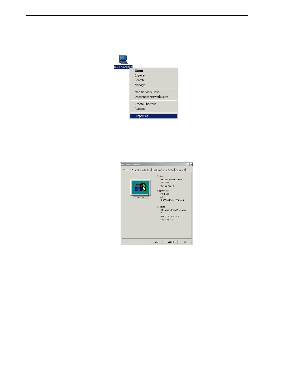
Follow these steps to determine which version of Windows Workstation is running on the base PC:
• Locate the icon labeled My Computer on the Windows Desktop. With the mouse, right-click
Installation 5
Page 22
53MT6000 INSTRUCTION MANUAL
on this icon. The screen should appear as shown in Figure 3-1.
Figure 3-1. My Computer Icon and Menu
• From the drop-down menu that appears, select the Properties item. The System Properties
window will appear as shown in Figure 3-2.
Figure 3-2. System Properties Window
If the General tab is not selected, select it. The operating system version appears as shown in Figure 3-2.
Verify that Windows 2000 Professional, or Windows XP Professional is installed.
3.3 Hardware Installation
3.3.1 Installing the Hardware Key
A Hardware Key is supplied when one of the standalone versions of Micro-Tools is specified in the model
number (refer to Section 1.3).
The Micro-Tools software is licensed by MicroMod Automation Inc. The license is protected by a hardware
key (see Figure 3-3), which must be attached to the PC's parallel port. The hardware key does not interfere
with the operation of the parallel port. When installed, the hardware key provides a fe male connector allow-
6 Installation
Page 23
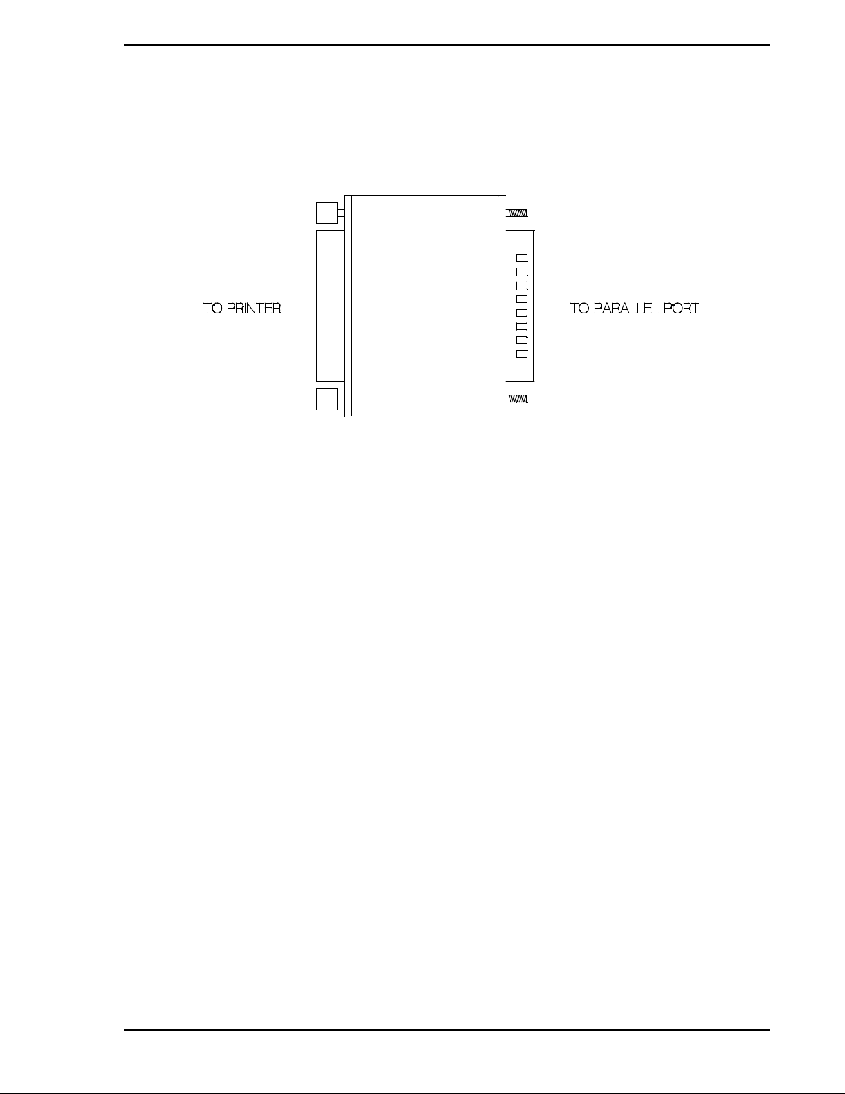
53MT6000 INSTRUCTION MANUAL
ing a parallel device to be attached to it. If a device (for example, a printer) is alr eady connected to the pa rallel port, remove the parallel cable connector, connect the hardware key to the port, and reconnect the
cable to the hardware key. Signals to and from the attached parallel device will be passed through the
hardware key. The hardware key must be installed for the Micro-Tools software to run.
Figure 3-3. Hardware Key for Use with Micro-Tools System Software
Installation of Micro-Tools software and licenses (Section 3.4) can proceed if the hardware key is not
attached; however, the Micro-Tools application will not start. Instead, a pop-up window will be displayed
which states:
Can't read hardware key.
Key must be attached to parallel port.
If the wrong hardware key is attached to the parallel port, a pop-up window will display the following message:
No valid Micro-Tools software license found.
If problems reading the hardware key persist, test the operation of the parallel port. This can be done by
attaching a printer to the port and attempting to print to it.
3.3.2 Connecting Micro-DCI Instruments to the Base PC
The connection necessary for this communication can be made in one of several ways:
• The computer's COM port can be connected directly to the mini-DIN configuration port on the
front of the controller, as described in Section 3.3.2.1.
• A COM port on the computer can be connected to one or more controllers via their DataLink
port using an RS232/485 Interface Terminal Board (ITB) that converts the RS-232 signals
used by the computer's COM port to the RS-485 signals used by the DataLink instruments.
This scheme is described in Section 3.3.2.2.
• If the computer contains a DataLink SUPERVISOR card, each card can be connected to one
or more controllers via their DataLink port (refer to Section 3.3.2.3).
• If the computer contains MicroLink SUPERVISOR cards, each card can be connected to a
MicroLink peer-to-peer network. If each stan dard M i croL ink SUPERVISOR card is paired with
a Redundant MicroLink SUPERVISOR card, the computer can communicate with one or two
redundant MicroLink networks.
Installation 7
Page 24

53MT6000 INSTRUCTION MANUAL
3.3.2.1 Connecting to a Single 53MC5 00 0 Co n trolle r
To connect a computer COM port on the computer to a single 53MC5000, all you need are:
• an available COM port on the computer
• a cable to connect the COM port with the mini-DIN configuration port on th e front of the
controller (behind the flip-down door below the display).
An appropriate cable is MicroMod Automation P/N 698B184U01. Six feet ( 1.8 m) in length, the cable has a
DIN connector on one end and a 9-pin connector on the other.
If your COM port requires a 25-pin connector, use one of these two options:
• buy an adapter locally to use the 9-pin cable
• order MicroMod Automation cable P/N 698B183U01; it has a 25-pin connector instead of a
9-pin connector
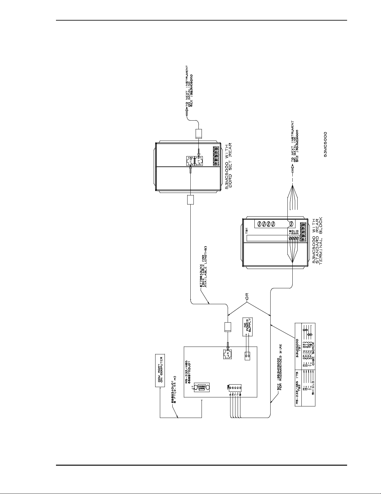
3.3.2.2 Connecting a COM Port to a DataLink Network
A COM port on the computer can be connected to a DataLink network using a special Interface Terminal
Board (ITB) (P/N 686B720U01) that converts the RS-232 signals used by the computer's COM port to the
RS-485 signals used by the DataLink instruments.
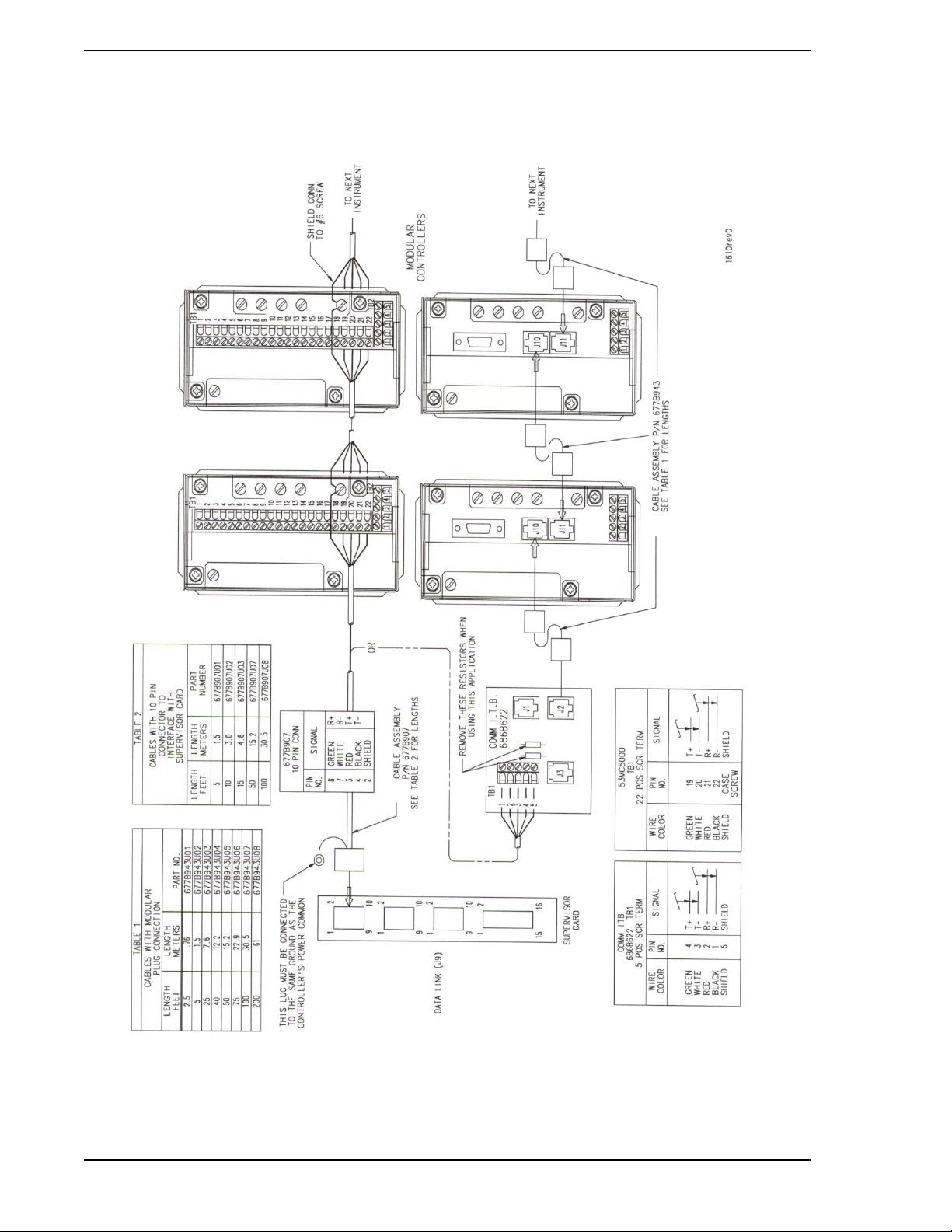
This connection scheme is illustrated in Figure 3-6. Note that this drawing shows how to connect the special RS-232/RS-485 ITB to the first 53MC5000 on the DataLink (both standard rear terminal block and
optional cord set rear connection are shown) . For de tails concerning the rest of the DataLink (which is
essentially a "daisy chain" of instruments), its termination, and suitable wire, consult the installation section
of the 53MC5000 instruction bulletin.
Note that Figure 3-6 shows a cable used to connect the ITB with a 53MC5000 having the cord se t o ption.
This cable is available in many lengths; the part numbers are shown in Table 1 of Figure 3-6.
3.3.2.3 Installing MicroLink or DataLink SUPERVISOR-PC Cards
To install the SUPERVISOR-PC cards, perform the following procedure:
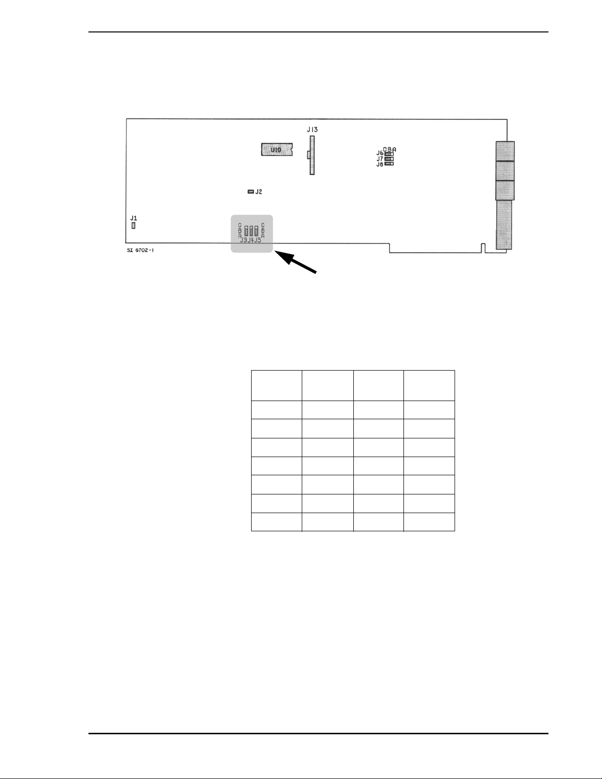
1. Properly set the SUPERVISOR-PC card jumpers. All SUPERVISOR-PC cards are identical
when shipped. It is the installer's responsibility to check jumpers J3, J4 and J5; these jumpers
set the base address in the PC I/O address space. (Refer to Figure 3-2 for jumper terminal
locations and Table 3-1 on page 9 for jumper settings.)
2. Turn off power to the computer and install the cards. A maximum of four
SUPERVISOR-PC cards can be installed. Plug each card into any available ISA slot and
secure each card with a screw through its mounting bracket.
3. If a redundant MicroLink card is required, it must be installed in the slot immedi ately to the right
of the MicroLink SUPERVISOR card; connect the ribbon cable connecting the two cards into
J13.
8 Installation
Page 25
53MT6000 INSTRUCTION MANUAL
4. Connect the Instrument DataLink cable to th e T OP connector at the rear of the SUPERVISORPC card.
J
Figure 3-4. SUPERVISOR-PC Jumper Terminal Locations
Table 3-1. Selecting Supervisor Board Base Address With Jumpers J3, J4, and J5
Base
Address
300H AB AB AB
310H AB AB BC
380H AB BC AB
390H AB BC BC
3A0H BC AB AB
280H BC AB BC
290H BC BC AB
3.3.2.4 Connecting Micro-Tools to the DataLink Network
Once a DataLink SUPERVISOR card is installed in the computer, connect the SUPERVISOR card to the
DataLink network using the port provided on the card.
If your controllers have standard rear terminal connections, making this connection requires only one
cable. This cable has a 10-pin connector with a grounding lug on one end and five bare wires on the other.
Cables may be ordered using the part numbers shown in Table 2 in Figure 3-6.
1. Plug the 10-pin connector on the cable to the port at the top of the SUPERVISOR ca rd. This
connector is the key to insuring a proper installation.
J3 J4 J5
2. Connect the connector's grounding lug to the same ground as the DataLink instruments'
power common.
Installation 9
Page 26

53MT6000 INSTRUCTION MANUAL
3. The bare wire end of the 677B907 cable can be connected to the first controller's standard
rear terminal connector as shown in Figure 3-6.
If your controllers are equipped for optional rear cord sets, making this connection requires:
• The Communications ITB 686B622U01.
• A modular cable 677B943Uxx; this cable has a telephone-type modular connector on each
end. (See Table 1 in Figure 3-6 for part numbers and available cable lengths.)
If your controllers use optional cord sets, connect the bare wire end of the 677B907 cable to the terminals
on the communication ITB. Remove the resistors on the ITB as shown in Figure 3-6. Then connect a
677B943 modular cable to J1, J2 or J3 on the IT B an d to J10 o r J11 on the first instrument in the DataLink
as shown in Figure 3-6.
3.3.2.5 Connecting Micro-Tools to the MicroLink Network
Once a MicroLink SUPERVISOR card is installed in the computer, connect the SUPERVISOR card to the
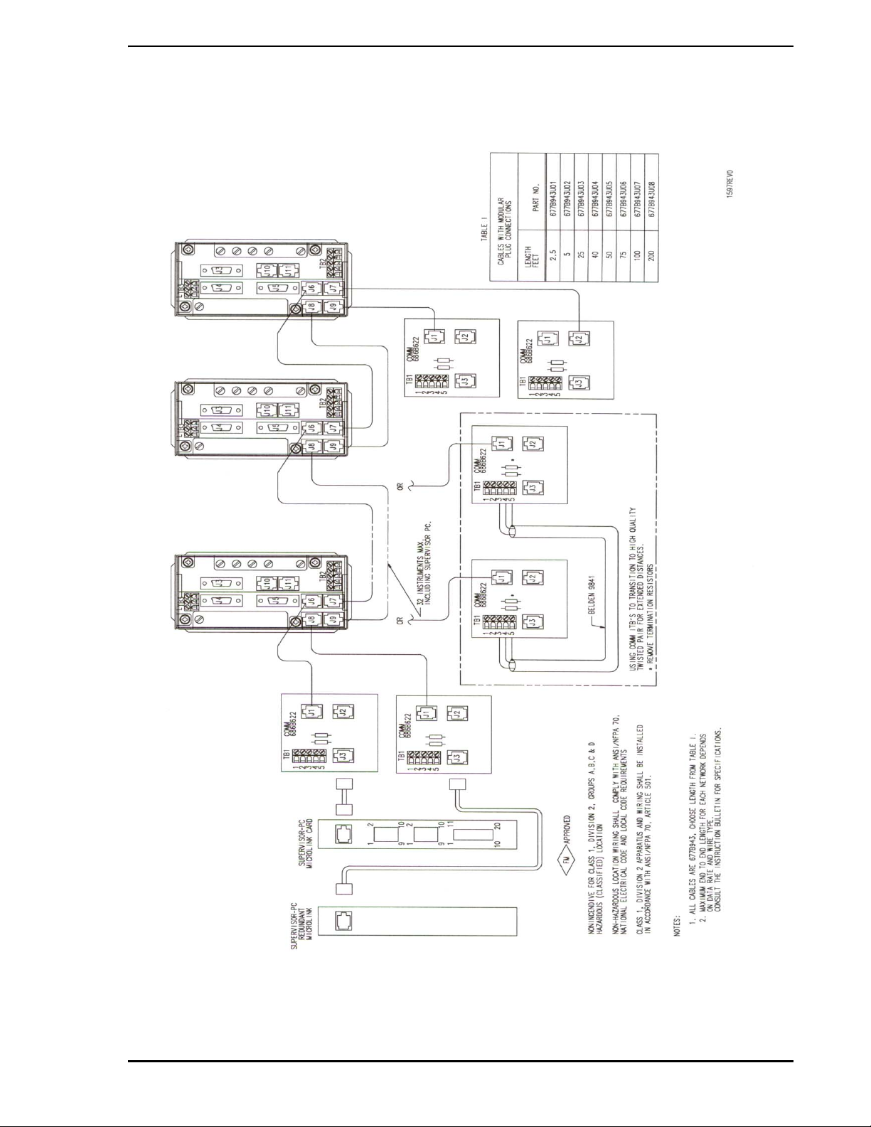
MicroLink network. Making this connection requires:
• one modular cable to connect the MicroLink SUPERVISOR card to the Communications ITB.
Cable 677B943Uxx can be ordered in several lengths as shown in Table 1 in Figure 3-7.
• one communications ITB (Interconnection Terminal Board) P/N 686B622U01
• one modular cable is required to connect the Communication ITB to the fir st instrument on th e
MicroLink network. Cable 677B943Uxx can be ordered in several lengths as shown in Table 1
in Figure 3-7.
1. Plug one end of the 2.5 ft (.76 m) modular cable into the port at the top of the MicroLink
SUPERVISOR card.
2. Plug the other end of the same modular cable into J1, J2 or J3 on the Communications ITB.
Leave the resistors on the ITB (refer to the MicroLink Instruction Bulletin for resistor sizing).
The purpose of this ITB is to serve as a termination for the network.
3. Plug one end of a second modular cable (P/N 677B943) into one of the remaining unused
plugs (J1, J2 or J3) on the ITB.
4. Plug the other end of this second modular cable into J6 or J7 on the first controller on the
MicroLink network.
If you are using a Redundant MicroLink continue with the following steps.
5. Plug a third 2.5 ft (.76 m) modular cable pr ovided with the Red undant MicroLink option into th e
connector on the Redundant MicroLink Supervisor card.
6. Plug the other end of this third modular cable into J1, J2 or J3 on the second Communication
ITB provided. Leave the resistors on this ITB, also (refer to the MicroLink Instruction Bulletin
for resistor sizing).
7. Plug one end of the fourth modular cable (P/N 677B943) into one of the remaining unused
plugs (J1, J2 or J3) of the ITB.
8. Plug the other end of this fourth modular cable into J8 or J9 of the first controller on the
MicroLink network.
10 Installation
Page 27
53MT6000 INSTRUCTION MANUAL
Figure 3-5. Connecting the Computer’s COM Port to the DataLink
Installation 11
Page 28
53MT6000 INSTRUCTION MANUAL
Figure 3-6. Micro-Tools DataLink SUPERVISOR Card to DataLink Interconnection Diagram
(ID-53-1610)
12 Installation
Page 29
53MT6000 INSTRUCTION MANUAL
Figure 3-7. Micro-Tools MicroLink SUPERVISOR Card to MicroLink Interconnection Diagram
(ID-53-1597)
Installation 13
Page 30

53MT6000 INSTRUCTION MANUAL
3.4 Installing the Micro-Tools Software
Now the process of installing the Micro-Tools software can begin.
3.4.1 Pre-Setup Procedure
• Check that the Micro-Tools hardware security key is connected to the parallel port of the
computer.
• Have the software license key(s) ready.
• Power on the base PC and boot the Windows Workstation software.
• Log on to the Windows Workstation software with administrative privileges. You must have
administrative privileges or the installations process will not complete successfully.
• Close all Windows applications that are open, (such as Microsoft Word, Excel, Mail,
Scheduler, etc.).
3.4.2 Beginning Micro-DCI Master Setup
• Insert the Micro-DCI CD into the CD-ROM drive.
• If the CD-ROM drive is configured for automatic startup, the Micro-DCI Master Setup window
should open automatically . If the CD does not start automatica lly , click on the Windows START
button and select Run from the menu. Click the Browse button and navigate to the CD-ROM
drive and the setup.exe file. Once the path to the setup.exe file has been selected, click OK to
open the Micro-DCI Master Setup window.
• In the Micro-DCI Master Setup window, click on the Micro-Tools Setup button to begin the
Micro-Tools installation procedure and start the InstallShield Wizard.
3.4.3 Beginning Micro-Tools Installation
• When the InstallShield Wizard is loaded, the Micro-Tools System Setup window appears.
• Click Next to begin installing Micro-Tools.
If the Micro-DCI Communications Services are being installed for the first time, the setup routine
will prompt for them to be installed. Click on the "OK" button and prompts will appear for Section
3.4.4 through Section 3.4.9. Otherwise these items will be skipped and the installation process will
proceed to Section 3.4.10.
3.4.4 Micro-DCI Communications Services Setup
• The Micro-DCI Communications Services Setup window appears. Click on the Next button to
proceed.
14 Installation
Page 31

53MT6000 INSTRUCTION MANUAL
3.4.5 Micro-DCI Communication Services Location
•The Choose Destination Location window appears, which enables you to specify the drive
and directory where you want the Micro-DCI Communication Services installed. You can
accept the default path of C:\udci by clicking the Next button or you can change the
destination directory by clicking the Browse button.
• If you clicked the Browse button, enter both the drive and directory you want to use as the
destination directory in the Choose Directory field.
• Click the Next button.
• If the directory does not exist, Setup will ask you if it should be created. If this window
appears, click the Yes button.
•The Select Program Folder window appears. Select the program Folder you want the
program icons added to. The Micro-DCI Comm Services folder is selected by default as the
folder for the program icons. You can accept the default, select an existing program folder,
or type a new program folder.
• Click the Next button.
•A Setup window with a progress bar appears and the Micro-DCI files begin to install.
•The Enter Information window appears and prompts you to enter a maximum of eight
characters as a name for your entire Micro-DCI local system.
• Either accept the default name or enter a name and click the Next button.
✎ NOTE If this PC is a node on a Micro-PWC, the selected name will be
used to identify the Micro-DCI communication interface on this PC;
therefore this name must be unique from all other node names on
the network.
The progress bar then finishes updating and the Setup process continues.
3.4.6 Installing Data Access Objects (DAO)
• If DAO 3.5 is already present on the system, this phase of the installation will be bypassed.
• Micro-Tools uses Data Access Objects (DAO's) to store local databases. If Microsoft DAO 3.5
has not been previously installed, Micro-Tools instructs you to run the DAO Setup from the
Micro-DCI Master Setup menu. This may be done any tim e after the comp le tio n of the MicroTools installation.
3.4.7 Installing the Micro-DCI Communications Services & Program Folder
• The Micro-DCI Communications Services will be automatically installed. A window will pop up
to install these services.
• When the services are installed, the window will close and return you to the Main Micro-Tools
Setup.
• The Micro-DCI Communications Services Setup program then creates the Micro-DCI
Communications Services program folder and automatically adds the appropriate icons for
the Micro-DCI Communications Services product.
Installation 15
Page 32

53MT6000 INSTRUCTION MANUAL
3.4.8 Adding Micro-DCI Networks
If you would like to add Micro-DCI instrument networks, click on the Yes button when given the choice. The
Add Micro-DCI Networks window appears. Click the Next button.
• The Setup program then starts the Super32 Network Addition program which enables you to
add Micro-DCI network instruments to your system. This is a good time to add MicroDCI networks to your system since you need to reboot your PC after installing the Micro-Tools
software and after you install the Micro-DCI networks.
• The first Network Wizard window lets you select whether you are adding a netwo rk that
is connected to your system through a supervisor board (SUP) or tho ugh a COM port ( COM).
Select either SUP or COM. Then click the Next button.
• Enter a Network Name (up to a maximumm of 9 characters) in the Network Wizar d - Network
Attributes window and select a Network Position. Then click the Next button.
3.4.8.1 COM: PC Serial Com Port Network Addition
• The Network Wizard - Backup window appears. Click the Next button.
• The Network Wizard - Network Parameters window appears. The parameters
change depending on the type of network that is being installed.
• In the Network Wizard - Finish window, click the Finish button .
• A window appears confirming that the "Network was added successfully". Click the "ok" button
to proceed.
• If the network was added successfully, Super32 will ask if another network is to be added. If
so, repeat the above steps until all desired Micro-DCI networks h ave bee n adde d. An swer ing
No exits Super 32 and opens the Read-Me file in a Notepad window.
3.4.8.2 SUP: MicroDCI Supervisor Network Card
• The Network Wizard - Backup window appears. Select Master or Backup and then click the
Next button.
• The Network Wizard - Network Parameters window appears. Set the I/O Port Address to
agree with the address jumpers on the Supervisor Board. The parameters change depending
on the type of network that is being installed.
• After selecting the I/O Port Address, click the Next button.
• In the Network Wizard - Finish window, click the Finish button .
• A window appears confirming that the "Network was added successfully". Click the OK button
to proceed.
• If the network was added successfully, Super32 will ask if another network is to be added. If
so, repeat the above steps until all d esire d Micro- DCI ne tworks ha ve been ad ded. Answer ing
No exits Super 32 and opens the Read-Me file in a Notepad window.
• Close the Notepad window to continue.
3.4.9 Selecting the Target Location for the Micro-Tools System
•The MicroTools Target Location window appears, which enables you to specify the drive
and directory where you want Micro-Tools installed. You can accept the default path of
C:\MicroTools by clicking the Next button or you can change the destination directory by
clicking the Browse button.
16 Installation
Page 33

✎ NOTE If re-installing Micro-Tools, an information window alerts you that
the microtools.exe file already exists; click ok. If it exists in the
same location you are installing to, you can choose to overwrite the
file or keep the previous version.
• If you clicked the Browse button, enter both the drive and directory you want to use as the
destination directory in the Choose Directory field .
• If the directory does not exist, Setup will ask you if it should be created. If this window
appears, click the Yes button.
• Click the Next button.
•A Setup window with a progress bar appears and the files begin to install.
•The Select Program Folder window appears. Select the program Folder you want the
program icons added to. The MicroTools folder is selected by default as the folder for the
program icons. You can accept the default, select an existing program folder, or type a new
program folder.
• Click the Next button and follow the prompts until the installation is completed.
3.4.10 New Program Folder
• The Micro-Tools Setup program then creates the Micro-Tools program folder and
automatically adds the appropriate icons for the Micro-Tools product.
53MT6000 INSTRUCTION MANUAL
3.4.11 Integrating Into Super32
• Micro-Tools can be registered to be the default configuration program for MC5000 controllers
in the Super32 Micro-DCI network management utility.
• When asked if Micro-Tools should be integrated into Super32, select Yes to register MicroTools as the default configuration program or No to use the Super32's basic MC5000
configuration program.
3.4.12 Installing the Micro-Tools License Keys
• Setup will launch the Micro-DCI License Administration program to enter your license keys.
Skip this step by, closing the license window, if the license keys were previously installed.
•Select Add new license... from the License menu.
• In the License Administration dialog, type in your license information for each license key
one at a time. Be certain to enter all information exactly as it appears. Click Save and this
information will be verified and written to the license file. If the information entered is not
correct, a pop-up message box will appear and the information will have to be corrected.
The following license keys are used:
udci - licenses Micro-DCI Communication Services for 300 tags
udciunlim - licenses Micro-DCI Communication Services for unlimited tags
microtools -
microtools1 - supplied with basic functionality version
microtools2 - supplied with full functionality Micro-PWC add-on
microtools3 - supplied with full functionality stand-alone
Installation 17
Page 34

53MT6000 INSTRUCTION MANUAL
✎ NOTE Entry of the 20-character License Keys is not case-sensitive. The
spaces between characters is for legibility only and should NOT be
entered as part of the License Key.
• Repeat the above steps for each license key.
• When finished, select Exit from the File menu.
• At this point the Notepad application opens and a Micro-Tools Read Me file appears
containing Micro-Tools release information. When you have finished reading this document,
close Notepad.
• Setup will now ask if you want to restart the PC.
•Select Yes and then click the OK button to restart the PC.
• This completes the setup process.
18 Installation
Page 35

53MT6000 INSTRUCTION MANUAL
4.0 START-UP
4.1 Micro-Tools Startup
When 53MT6000 Setup is complete, the following Windows Menu Group is created:
Figure 4-1. MicroTools Windows Menu Group
The function of the icons contained in the Micro-Tools Menu Group are detailed below:
This menu item loads and begins running the Micro-T ools
application.
Provides on-line HELP information as an aid to resolving operational
problems.
Double-click on the Read Me icon for important information about
this software release.
Selecting this menu item removes the 53MT6000 software from the
system.
When Micro-DCI Communications Services has been installed successfully, the following Windows menu
group will be created:
Figure 4-2. Micro-DCI Communications Services Windows Menu Group
Start-up 19
Page 36

53MT6000 INSTRUCTION MANUAL
The function of the icons contained in the Micro-DCI Communications Services Menu Group are
detailed below:
The Micro-DCI DDE Server provides data in "tag.atom" format
to DDE clients such as Microsoft Excel.
Double-click on the License Admin icon to add or edit license
keys.
Double-click on the Read Me icon for important information
about this software release.
Super32 is the Micro-DCI network administration program used
to configure networks, instruments, tags, etc. Double-click this
icon to start Super32. For more information, see the 53SU6000
Configuration Guide, PN24828.
Double-clicking on the Uninstall Micro-DCI Communi ca ti on s
Services icon removes the 53SU6000 and all associated
components from the system.
20 Start-up
Page 37

53MT6000 INSTRUCTION MANUAL
5.0 OVERVIEW OF USER INTERFACE
Because the Micro-Tools software runs under the Microsof t Windows operating system, the po int-and-click
user interface with its menu bars, pop-up windows, radio buttons, and so on, should be familiar to many
users.
5.1 Starting the Micro-Tools Software
The setup program for the Micro-Tools software adds the Micro-Tools icon to a program group called
"Micro-Tools" by default. Clicking on the Micro-Tools icon starts the Micro-Tools application.
If Super32 is installed, Micro-Tools may also be started from within the Super32 window by clicking on a
controller icon.
5.2 The Micro-Tools Window
The Micro-Tools (Administrator) and Project Manager windows (Figure 5-1) are opened by clicking on the
Micro-Tools icon. The Administrator window includes the following:
• title bar with sizing controls
• menu bar
• status bar
• project toolbar
• application toolbars
If Micro-Tools is started by clicking on an "on-line" controller icon from within Super32, the Micro-Tools
(Administrator) and Database Editor windows (illustrated in Figure 5-1) are opened. The Administrator win-
dow includes the following:
• title bar with sizing controls
• menu bar
• status bar
• project toolbar
• application toolbars
Overview of User Interface 21
Page 38

project toolbar
53MT6000 INSTRUCTION MANUAL
application toolbar
title bar with sizing controls
menu bar
status bar
Figure 5-1. Micro-Tools Window
22 Overview of User Interface
Page 39

5.3 Toolbars
5.3.1 Project Toolbar
Project Selector Specify the default project to be configured using the Micro-
Project Manager Access project files for configuration.
Database Editor View and edit the Database.
53MT6000 INSTRUCTION MANUAL
Tools tools.
Flexible Control
Strategy
Control
Interconnection
Modules
F-TRAN Editor View, edit and compile F-TRAN Language for control,
F-TRAN Builder Use the information stored in the controller folder to build a
Download Download the configuration file to the specified controller.
Upload Upload a 53MC5000 configuration to the Micro-Tools
Graphically configure the Flexible Control Str ategy.
Graphically configure the Control Interconnection Modules.
display and sub-routine program files. Check the files for
errors.
downloadable 53MC5000 program.
computer.
On-line Configuration Directly configure the 53MC5000 in real-time.
Overview of User Interface 23
Page 40

53MT6000 INSTRUCTION MANUAL
5.3.2 Application Toolbar
The tools available on the Application Toolbar will vary with the operation being performed. Refer to the
Online Help for specific toolbar information.
5.4 Status Bar
The status bar at the bottom of the main Micro-Tools window contains an edit box, tool type field and displays the coordinates of the cursor position.
The edit box can be used to enter tool commands and location coordinates, permitting placement of graphical elements at exact locations when configuring func tion block diagrams an d other graphical obje cts. See
the Appendices for information on Tool Commands.
Another field in the status bar is used by some tools to show the tool type which is currently selected.
5.5 Cursor and Mouse Conventions
The shape of the cursor can vary, depending on the current activity or location. The cursor shapes in the
table below are representative.
The cursor and mouse in combination can be used in a variety of ways as shown in the table below. Note
that not all functions apply to every window.
✎ NOTE When referring to "left" and "right" mouse buttons, a right-handed
mouse button configuration is assumed.
Table 5-1. Cursor Status By Cursor Shape
Cursor Status Cursor Shape
In text entry box
On Help window “hot spot”
Dragging-and-dropping a file name
Standard cursor
(may appear different from the picture)
On project tables
The cursor and mouse in combination can be used in a variety of ways, as shown in the table below. Note
that not all functions apply to every window.
I
*
Û
✚
24 Overview of User Interface
Page 41

53MT6000 INSTRUCTION MANUAL
Table 5-2. Cursor/Mouse Functions
Function Action
select an item Position the cursor on the item, then click the left mouse button.
perform default
action for an item
display a list of
functions specific to
an item
drag-and-drop an
item
select a region Position the cursor at one corner of the region and press the left mouse
✎ NOTE Any time the instructions in this manual or in the Help system tell
Position the cursor on the item, then double-click the left mouse button.
Position the cursor on the item and click the right mouse button to display
the object menu.
Position the cursor on an item on the screen, then press the left mouse
button and hold while moving the mouse until the selected item is in the
desired location. Release the button.
button, then move the cursor until it is at the diagonally opposite corner of
the region. Release the mouse button.
you to click on an item, or to drag-and-drop an item, use the LEFT
mouse button, unless told otherwise.
5.6 Accessing On-Line Help
Many windows, such as pop-ups, provide a HELP button to access context-sensitive Help. For those windows without a HELP button, the
? button, available on the application toolbar, can be used to get Help.
You can also access the Help system using the Help item on the Micro-Tools window menu bar to display
the Help menu. The items on the menu provide access to Help in a variety of ways. "How to Use Help"
instructions are also accessible from this menu.
5.7 Specifying a Default Project
The first step in using most Micro-Tools tools is to specify a project, then to pick an item to create or edit. If
you plan to use several tools to work on the same project during a Micro-Tools session, it is advantageous
to use the drop-down combo-box on the Project Toolbar to specify a default. Once you have specified a
default, every selection window you open will list items relevant to that project.
If a default project has been specified, you can still use the open selection window to temporarily pick a different project, or you can quickly change the default.
Overview of User Interface 25
Page 42

53MT6000 INSTRUCTION MANUAL
26 Overview of User Interface
Page 43

53MT6000 INSTRUCTION MANUAL
6.0 THE MICRO-TOOLS PROJECT MANAGER
The Micro-Tools package is designed to be used to configure a whole project, not just a single database
(although configuration of an individual dat abase within a p roject is suppor ted). A project con sists o f all the
software resources needed to control an entire process, or a process area. The project management activities performed by the Micro-Tools software go on behind the scenes, keeping track of all the co nfiguration
work in the project, and where it is stored.
In addition to the project management activities that are transparent to you, there is also a PROJECT
MANAGER window, accessed from the Project Toolbar. This window makes it easy for you to view your
project and to access anything in your project or Micro-Tools library at any time.
The Micro-Tools Project Manager Window is shown in Figure 6-1. Note that the Project Manager consists
of a hierarchy of folders. The folders are arrang ed to organ ize controller information. Seve ral st andard folders are included that contain the 53MC5000 standard control strategies.
Figure 6-1. Project Manager Window
Micro-Tools Project Manager 27
Page 44

53MT6000 INSTRUCTION MANUAL
6.1 Project Manager Window
The Micro-Tools PROJECT MANAGER window provides a hierarchical view of how information is stored
within the project, and within individual controller "folders" under the project.
6.1.1 Opening the Window
The PROJECT MANAGER window (shown in Figure 6-1) opens automatically when the Micro-Tools application is started from the Windows Project Manager. If the window has been closed, it can be opened by
clicking on the button (Project Manager) in the project toolbar.
If Micro-Tools was opened by selecting a controller icon from within Super32, the Micro-Tools Database
Editor window is opened. You can open the PROJECT MANAGER window by clicking on the Project
Manager button in the project toolbar.
Note that the window in Figure 6-1 is labeled with the path to the project. If the PROJECT MANAGER window contains nothing but a slash (/) character symbolizing the root of the hierarchy, double-click on it to
display the hierarchy.
6.1.2 The Hierarchical View
The PROJECT MANAGER window displays the tree (or hierarchy) for a ll Micro-Tools projects registere d in
the Micro-Tools database.
The hierarchical view in the PROJECT MANAGER window includes folders for various types of entities in
the Micro-Tools project. The folders do not necessarily reflect the physical locations where information is
stored. You do not have to concern yourself with the actual location of a particular piece of configuration
data; the Micro-Tools Project Manager handles storage and retrieval of configuration data for you.
Note that the hierarchy always includes the folder named library, used to store templates of function
blocks, modules and standard control strategies (applications). Copies of these modules are available for
use in any project.
A folder may be opened by double-clicking on it with the left mouse button. Once a folder is opened, the
display also includes a list of items (objects and files) in the selected folder.
6.1.2.1 Project Folder Hierarc h y (Tree View)
As mentioned earlier , the Project Manager is arranged into a hierarchy (or T ree) of folders. The top level of
the hierarchy is the Project Manager folder denoted by the folder and backslash.
The small plus sign to the left of the folder designates that there are unde rlying file s or folders. By clicking
on the plus symbol, the next level in the hierarchy (next branch in the tree) is displayed. This next level in
the Project Manager contains two folders, the Library folder and the Project folder.
✎ NOTE: The plus sign next to the controller may be hidden until the folder is
highlighted by clicking on the folder.
28 Micro-Tools Project Manager
Page 45

53MT6000 INSTRUCTION MANUAL
The Library folder contains all the standard control strategi es for FCS (Flexible Control Strategies) and
FCIM (Flexible Control Interconnect Modules). The Library will also contain the standard report structures
and drawing borders. Users may add their own configuration to the Library as a common source for
project applications.
Figure 6-2. Library Folder Contents
The Project folder is the location where all the controller project s are m aint ained. A proje ct is essentially a
collection of one or more controller applications. A project can represent an area of a plant site, an individual application revision levels or any other creative way of grouping controller applications. As implied,
project names are user definable and must be unique.
Figure 6-3. Project Folder Examples
Project folders may contain one or more folders representing controllers. A controller’s configurations,
database, programs and reports are maintained within a commo n fold e r for eac h co ntr o ller. The name of
Micro-Tools Project Manager 29
Page 46

53MT6000 INSTRUCTION MANUAL
the controller folder should match the contro ller’s tagname (each controller has a user configu ra b le tagname). Protections within the software, prevent a controller’s information from being loaded into the wrong
controller by linking the respective controller files to the controller name.
6.1.2.2 Folder Commands
Right-clicking on a folder displays commands that can be used on that folder . Gener ally these command s
are used to add or remove items from the fold e r.
These folder commands provide a shortcut to functions that are also accessible from menus and tool windows.
6.1.2.3 Shortcuts
Folder commands can be shortcuts. For example, the Contr ol folder within the F-TRAN Programs folder
contains commands that let you create a new F-TRAN file from the PROJECT MANAGER window. Alternatively , you could click FILE > NEW > F-TRAN FILE, or enter an F-TRAN fi lename in the F-TRAN Edito r’s
OPEN F-TRAN FILE window.
Another PROJECT MANAGER shortcut is the ability to access any information or item listed in the window
simply by double-clicking the item with the left mouse button. For example, if you double-click on the nam e
of a F-TRAN file, the F-TRAN EDITOR window will open. The window will contain the file you selected
from the PROJECT MANAGER window.
To display the menu listing functions available for the item, including printing, click on the object or filename
with the right mouse button.
30 Micro-Tools Project Manager
Page 47

53MT6000 INSTRUCTION MANUAL
6.2 How to Create a Project
Use one of the following methods to access the dialog box used to enter the name of a new project:
•Select PROJECT > NEW PROJECT.
Figure 6-4. Create a New Project, Method 1
•Select FILE > NEW > PROJECT.
or
Figure 6-5. Create a New Project, Method 2
• Right-click on the PROJECT folder in the Project Manager Tree and select NEW PROJECT
Figure 6-6. Create a New Project, Method 3
Micro-Tools Project Manager 31
Page 48

53MT6000 INSTRUCTION MANUAL
6.3 Project Backup and Restore
The complete project database can be backed up to another directory, or to a drive containing a removable
medium. Right-click on the project to be backed-up. Select Backup. Choose a location and a na me for the
resulting backup file.
Backing up project data can be done to safeguard data as well as copy data to other machines. As with
any software system, it is recommended that backups be done periodically. Backups can be done to floppy
disks, hard disk drives, tape or any other recordable m e dia . Bac ku ps are crea ted as a sing le compr es se d
file containing all the needed data. Backup files are created with the .MTB file extension.
To Backup your Micro-Tools library and all Project data:
Figure 6-7. Backing up the Micro-Tools Library and All Project Data
1. Choose FILE > BACKUP on the main menubar.
2. Choose a path and filename for the backup file. The file extension .MTB will be added
automatically.
To Backup only the library or a single project:
Figure 6-8. Backing Up the Library or a Single Project
1. Right mouse click the library or desired project in Project Manager.
2. Select the Backup menu option.
32 Micro-Tools Project Manager
Page 49

53MT6000 INSTRUCTION MANUAL
3. Choose a path and filename for the backup file. The file extension .MTB will be added
automatically.
To Restore all the project data in a backup file:
Figure 6-9. Restoring All Project Data in a Backup File
1. Choose FILE > RESTORE on the main menubar.
2. Select the desired backup file to be restored.
To Restore just the library or just a single project from a backup file:
Figure 6-10. Restoring Only the Library or a Single Project
1. Right mouse click the library or desired project in Project Manager.
2. Select the Restore menu option.
3. Select the backup file to be restored.
✎ NOTE: If the selected project does not exist in the backup file, an error
message will be issued.
Micro-Tools Project Manager 33
Page 50

53MT6000 INSTRUCTION MANUAL
6.4 Importing and Exporting Project Configuration Data
6.4.1 Importing
Several methods are provided to allow importing F-TRAN projects created using the 53HC3300 Custom
Program Interface Software.
6.4.1.1 Importing F-TRAN Project Files
An existing F-TRAN project can be imported automatically by right-clicking on the F-TRAN folder of the
desired controller. Choose Import from the pop-up me nu. From the file selection dialog that appears,
select the existing .P5S file that describes the project to be imported (Imports using th is method require
that the paths defined in the .P5S file be correct).
Figure 6-11. Importing F-TRAN Project Files
6.4.1.2 Importing Individual Control, Display and Subroutine F-TRAN Files
Existing F-TRAN source files can be imported by right-clicking on the Control, Display or Subroutine folde r
in the F-TRAN folder of the desired controller. Select Import from the menu. Choose the desired file from
the file selection dialog.
Figure 6-12. Importing Individual F-Tran Source Files
34 Micro-Tools Project Manager
Page 51

53MT6000 INSTRUCTION MANUAL
6.4.1.3 Importing the F-TRAN Image Only
In some situations, source-file F-TRAN files are not available. However, a copy of the F-TRAN image
(HEX) file will have been saved to disk. This image file may be imported to the controller folder F-TRAN
image. The F-TRAN image icon appears in the right panel of the Project Manager window when a controller folder is open.
Figure 6-13. Iimporting the F-TRAN Image Only
Micro-Tools Project Manager 35
Page 52

53MT6000 INSTRUCTION MANUAL
6.4.1.4 Importing the Controller’s Database
A hex file representation of a controller’s database can be imported by right-clicking on the database icon
that appears in the right panel of the Project Manager window when a controller folder is opened. Select
the Import option from the pop-up menu and choose a path and filename (.M5D) from the file dialog that
appears.
Figure 6-14. Importing the Controller’s Database
6.4.2 Exporting
6.4.2.1 Exporting F-TRAN Project Files
Individual Control, DIsplay and Subroutine F-TRAN files can be exported to the Custom Program Interface
software file formats. Select either the Control, Display or Subroutin e folder an d a list of the files withi n the
selected folder will appear on the right panel of the Project Manager. Right-click on the desired file and
select Export from the pop-up menu that appears. The appropriate file extension will be displayed.
6.4.2.2 Exporting the F-TRAN Image Only
A copy of the F-TRAN image (HEX) file may be exported to a .PSI file format suitable for downloading
using the 53HC3300 and 53SU5000 Micro-DCI products. Select the Export option by right-clicking with
the mouse on the F-TRAN image icon that appears in the right panel of the Project Manager window.
6.4.2.3 Exporting the Controller’s Database
A hex file representation of a controller’s database can be exported by right-clicking on the database icon
that appears in the right panel of Project Manager when a controller folder is opened. Select the Export
option from the pop-up menu and choose a path and filename fr om the file dialo g tha t appe ar s. The re su lting .M5D file is suitable for downloading using the 53 HC3300D and 53SU5000A Micro-DCI products.
36 Micro-Tools Project Manager
Page 53

53MT6000 INSTRUCTION MANUAL
6.5 Project Variables
Y o u can assign project-wid e values to variables used in the Micro-Tools report generato r. T o name the va riables and assign values open the Project Database folder in the respective project fo lder . A Variable Store
icon will be displayed.
Double click on the Variable Store icon to open the table shown in Figure 6-15. Name project variables
and specify a value for each.
Figure 6-15. Variable Store Assignment Window
Micro-Tools Project Manager 37
Page 54

53MT6000 INSTRUCTION MANUAL
38 Micro-Tools Project Manager
Page 55

53MT6000 INSTRUCTION MANUAL
7.0 DATABASE EDITOR
The Micro-Tools Database Editor provides a menu oriented configuration tool for viewing and setting the
values of the various parameters within the controller. The parameters within the controllers are organized
into "modules".
7.1 Accessing the Database Editor Window
The Database Editor window may be used in the off-line configuration of a project or the on-line config uration of a 53MC5000 instrument. There are several ways to access the Database Editor window, as
described in Section 7.2.
7.2 Selecting an On-Line or Off-Line Instrument Database to Configure
7.2.1 Specifying an Off-Line Instrument Database in a Project
There are two ways to access a database for Off-Line configuration:
• If a controller project folder is selected, the Database may be edited by right-clicking on the
Database icon that appears in the right panel of the Project Manager. Select Edit Off-Line
from the pop-up menu that appears.
• The Database Editor icon may be used to select a project folder and controller name
from within that folder.
When the Database Editor is accessed directly using the button on the Project Toolbar, the Select
Controller Name window will open. Select a project folder from the "project tree". Either an existing controller name can be selected from within the project folder or a new controller name may be created. To create a new database in the project enter a new name in the text entr y bo x.
When a new name is entered and then the OK button clicked, the message "Add <New Name> as a New
Controller" will open. Select YES to create a new Controller. A second dialog box will open requesting a
new controller Model Number to be specified. The model number is used to identify the capabilities of the
controller. Whe n creating the offlin e model number , MicroTools is unable to access this information directly
from the controller. The default model number may be used and updated at a later time. Click on the OK
button when finished.
The Database Editor window will open providing access to the database parameters for review and edit.
Database Editor 39
Page 56

53MT6000 INSTRUCTION MANUAL
7.2.2 Selecting an On-Line 53MC5000 to Configure
There are two ways to access a database for On-Line configuration:
• If a controller project folder is selected, the Database may be edited by right-clicking on the
Database icon that appears in the right panel of the Project Manager. Select Edit On-Line
from the pop-up menu that appears.
• The Network Viewer icon may be used to select a specific controller name from the
Super32 Treeview window.
∆ WARNING:
When using the Database Editor to specify a data point value
in an on-line controller, the change to the instrument’s
database is made as soon as you click on OK in a pop-up
window or when you press the ENTER key during editing of
the Data Tables.
If you do not want the change to affect your process
immediately, PUT THE 53MC5000 IN SUSPEND MODE
FIRST, before performing On-Line configuration.
To put the instrument into Suspend mode, select SUSPEND
from the Function Index drop-down menu. When you are
ready to resume controller operation, use the same dropdown menu to select the appropriate function index.
While the 53MC5000 is in Suspend mode, its outputs remain
at the last value before the unit was placed in Suspend.
However, IF YOU CHANGE THE VALUE OF ONE OF THE
53MC5000 OUTPUTS IN THE DA TABASE while the unit is in
Suspend, THE CHANGE WILL TAKE EFFECT
IMMEDIATELY. Think about the effects on your process
before changing an output!
7.3 Using the Database Editor Window
7.3.1 Overview
The top section of the editor window is used to display and specify the Unit Tagname (unit tagname of the
instrument), and to specify the Function Index (control strategy or controller mode) as de scribed in Section
7.3.2. The On-Line or Off-Line status of the editor is also displayed in the area.
The main body of the editor window shows the controller’s inputs (AI0-AI8 & CCI0-CCI17) and outputs
(AO0-AO3 & CCO0-CCO17). The current status of the inputs and outputs is also shown. If the editor is
On-Line, these values will change dynamically. Each input and output has a button associated with it. The
button is a link to the database parameters associated with the input or output. The collection of database
parameters for a specific purpose, such as an input or output, is referred to as a module. Clicking on a button activates pop-up windows used to view and/or change the values of the parameters. The relationship
between an input or output module and a field signal is described in Section 7.3.3.
On the right side of the editor window are buttons used to access other module parameters. These buttons include Control modules, Parameter modules, Status Display Templates, Totalizers, etc., and are
described in Section 7.4.
40 Database Editor
Page 57

53MT6000 INSTRUCTION MANUAL
One of the buttons on the right of the window is used to access the Data Tables. The Data Tables are a
comlete listing of every database location (also called datapoints) by its data type. Use of the Data Tables
is described in Section 7.4.14.
An Options button is used to access and modify the controller model number mentioned earlier.
7.3.2 Selecting a Function Index
The 53MC5000 contains a very important multi-purpose data point, B000. This data point used to store
the Function Index of the unit (often referred to as the FIX).
The Function Index may be displayed by using the drop-down combo box at the upp er left of th e Database
Editor window (shown in Figure 7-1) to specify a control strategy or a controller mode. (If this drop-down
box is used, the actual value to be stored in B000 need not be known. However, the information is presented so you can make the correlation between what you r ead here a nd what yo u r ead in the 53MC50 00
manuals.)
Use the Data Tables button (on the right of the window) to access the Data T ab l es , which display all data
points by their addresses. Use of the Data Tables is described in Section 7.4.14.
Use the Options button (also on the right side of the window) to access the Select MC5000 Options window. This window is used to specify the options supported by the target 53MC5000 during configuration of
an off-line database.
Figure 7-1. Database Editor Window
Clicking on the drop-down arrow of the Function Index combo box will yield the display illustrated in
Figure 7-2.
Depending on the value stored as a function index, the controller will perform one of the following actions:
• Go into suspend state (B000 = 0):
When the 53MC5000 is in suspend state, the MicroMod logo is the only display. In this mode,
the control program being executed stops, analo g control output s hold their la st value, cont act
outputs hold their last state, analog inputs continue to be measured, and the totalizers and
Database Editor 41
Page 58

53MT6000 INSTRUCTION MANUAL
Figure 7-2. Function Index Drop-Down Box
trends continue to update.
• Execute a Flexible Control Strategy (FCS) (B000 = 1):
The process control station performs control using one of the "canned" strategies supplied
with the controller, either "as is" or as modified by th e user. Which of the "FIX 1" strategies the
unit executes depends on the value assigned to a dif ferent d ata po int (B016). (T hese stan dard
strategies are referred to as CS1, CS2, etc., in the 53MC5000 Flexible Control Strategy
manual.) Once one of these control strate gie s has been specified, specific database values
are loaded and modules in the instrument are linked together to implement the strategy. The
actual values assigned to the data points fo r each strategy are listed in the 53MC5000 man ual.
Out of the box, the 53MC5000 is ready to perform one of these "FIX 1" strategies. A one-loop
unit will do CS1, single loop PID control. A two-loop unit will do CS20, a two PID control loop
strategy. A four-loop unit will do CS41, a four PID loop strategy.
• Test the display (B000 = 97):
A series of test patterns can be displayed. Displaying the test patterns does not disturb the
database, but the control program stops executing un til the function index is restored.
• Default the database (B000 = 98):
It is possible to set the controller’s database back to the factory settings by "defaulting the
database". In this situation, most data points are set to values specified by MicroMod
Automation. The default database values are listed in the Instruction Manual supplied with the
controller. The only values not affected are the analog I/O calibration constants, the controller
Model Number and a few other database locations. The default always loads a CS1, Single
Loop PID, control strategy.
42 Database Editor
Page 59

53MT6000 INSTRUCTION MANUAL
❢ CAUTION
IF DEFAULT THE DATABASE IS SELECTED (FIX98), ANY
EXISTING CONFIGURATION IN THE CONTROLLER WILL
BE OVERWRITTEN WHEN DEFAULT VALUES ARE
WRITTEN TO THE DATABASE.
• Execute the custom F-CIM sequence (B000 = 99):
The user can configure the controller to perform a custom sequence of up to 100 steps, each
step executing an F-CIM module (refer to the 53MC5000 Customization Guide).
• Execute a custom F-TRAN program (B000 = value of 2 to 89 or 101 to 255):
If the controller is an "extended functionality" unit, the user can write and execute custom
control programs (including custom displays if desired). More then one custom program (and
display) can be loaded simultaneously into the controller. Each custom control program is
assigned its own FIX number within the valid ran ges. When one o f these custom FIX numb ers
is assigned to B000, the 53MC5000 executes that particular custom program. Details of
creating custom control and display programs is described in the 53MC5000 Customization
Guide.
• Custom PROM support:
A special application of F-TRAN programming includes the creation of a custom PROM.
Normal F-TRAN programs are loaded into battery-backed RAM memory for execution. The
creation of a custom PROM allows the F-TRAN program to reside in PROM memory for added
protection or special customer applications. If you are interested in using a custom PROM for
a unique situation, contact your MicroMod Automation representative.
Database Editor 43
Page 60

53MT6000 INSTRUCTION MANUAL
7.3.3 Making Changes to a Module’s Configuration
When a module is selected from the main window, the module-specific window opens displaying the configurable parameters for the module. Information contained in the window may include numerical values,
alphanumeric strings or buttons representing logical choices. Windows with limited options will have drop
down menus from which to select options. As an example, Figure 7-3 shows the window opened if ANI0
was selected. (For more information on configuration parameters for any module types, see Sectio n 5.0 of
the 53MC5000 Modular Controller Instruction Manual.)
To change any parameter within a module window , click on the par ameter’s activation button, numerical or
text value, or drop down arrow button. Enter a new value, a s appropriate and select Save or OK. Changes
are executed immediately in the selected online controller or offline database image.
Using the ANI0 example:
• the tagname of the ANI will be stored in database location A224
• the engineering unit will be stored in A298
• the engineering span will be stored in C256
• the engineering zero will be stored in C276
• the input range will be stored in L416
• the input type will be stored in L440
• the smoothing (digital filter index) will be stored in B269
Changes are executed immediately in the selected online controller or offline database buffer but are only
stored temporarily until saved. When configuration of the module is completed, save the changes by
selecting Save or OK to return to the main Dat abase Edito r menu. Selectin g Cancel or closing the window
instead of selecting Save or OK will return to the main Database Editor menu without saving.
44 Database Editor
Figure 7-3. Example of a Submenu Window
Page 61

53MT6000 INSTRUCTION MANUAL
7.4 Sub-Menu Descriptions
The following sections describe the module windows displayed when each item is selected from the main
database editor window. For details concerning any of the parameters, see the Modular Controller Instruction Bulletin. Note that not all values are configurable; these are identified as "display only".
7.4.1 ANI Menu
The number of analog inputs per controller is dependent on the options purchased with the controller.
MicroTools provides access for all nine possible analog input modules (AI0 through AI8). The window for
each AI module contains the entries listed below.
ENTRY
Channel: Displays channel number
Tagname: Tagname
Eng. Unit: Engineering Unit
Signal: Selects analog or frequency input (only active for Channels
Bias: 1 - 5 or 0 - 5 volt
Digital Filter: Digital filtering; 0 is no filtering
Lin/Sqrt: Linear or Square root
Zero/Span: Full scale range in Engineering Units
Simulation: Allows manual modification of module output
OK: Saves changes, closes window and returns to main menu
Save: Saves changes without closing window
Cancel: Cancels changes and returns to main menu
EXPLANATION
4 through 7)
Figure 7-4. ANI Parameter Configuration Window
In the unlikely event that the calibration span and zero must be changed, see Section 7.4.18 for a description of adjusting calibration constants using the CALIBRATION menu.
Database Editor 45
Page 62

53MT6000 INSTRUCTION MANUAL
7.4.2 ANO Menu
The number of analog outputs per controller is dependent on the options purchased with the controller.
MicroTools provides access for all four possible analog output modules (AO0 through AO4). The window
for each AO module contains the entries listed below..
ENTRY
Channel: Displays channel number
Tagname: Tagname
Output: Selects between 4 - 20 or 0 - 20 mA output range
OK: Saves changes, closes window and returns to main menu
Save: Saves changes without closing window
Cancel: Cancels changes and returns to main menu
EXPLANATION
Figure 7-5. ANO Parameter Window
In the unlikely event that the calibration span and zero must be changed, see Section 7.4.18 for a description of adjusting calibration constants using the CALIBRATION menu.
46 Database Editor
Page 63

53MT6000 INSTRUCTION MANUAL
7.4.3 CCI Menu
The number of discrete (contact) inputs per contr olle r is dep end ent on the op tio ns pu rchase d with th e controller. MicroTools provides access for all eighteen possible discrete input modules (CCI0 through CCI17).
The window for each CCI module contains the entries listed below..
ENTRY
Channel: Displays channel number
Tagname: Tagname
Input: Selects between Inverting and non-Inverting operation
OK: Saves changes, closes window and returns to main menu
Save: Saves changes without closing window
Cancel: Cancels changes and returns to main menu
EXPLANATION
Figure 7-6. CCI Parameter Window
Database Editor 47
Page 64

53MT6000 INSTRUCTION MANUAL
7.4.4 CCO Menu
The number of discrete (contact) outputs per controller is dependent on the options purchased with the
controller. MicroTools provides access for all eighteen possible discrete output modules (CCO0 through
CCO17). The window for each CCO module contains the entries listed below.
ENTRY
Channel: Displays channel number
Tagname: Tagname
Output: Selects between Inverting and non-Inverting operation
OK: Saves changes, closes window and returns to main menu
Save: Saves changes without closing window
Cancel: Cancels changes and returns to main menu
EXPLANATION
48 Database Editor
Figure 7-7. CCO Parameter Window
Page 65

53MT6000 INSTRUCTION MANUAL
7.4.5 Menu
The button for the SYSTEM menu is at the right of the Database Editor window. The SYSTEM menu
allows the configuration of the SYSTEM module parameters described in the 53MC5000 Instruction
Manual. The SYSTEM module controls fundamental actions of the controller, such as the control program
scan rate or the display program scan rate.
Figure 7-8. System Configuration Window
Database Editor 49
Page 66

53MT6000 INSTRUCTION MANUAL
The window for the SYSTEM module contains the entries listed below:
ENTRY
Unit Tagname: Tagname of this instrument [A08]
Function Index: The value of the Function Index (FIX) is displayed.
EXPLANATION
The operating modes determined by this value are described in
the Instruction Manual. Briefly:
SUSPEND MODE [0]: The control program is not running,
although inputs continue to be measured, and totalizers and
trends continue to update. Outputs reflect the contents of their
associated database points. The display will show the MicroMod
Automation logo.
FLEXIBLE CONTROL STRATEGY [1]: The controller is running
one of the built-in Flexible Control Strategies described in the
FLEXIBLE CONTROL STRATEGY guide.
DISPLA Y TEST [97]: A series of three test patterns will appear on
the controller’s display. The control program is stopped, but the
database is unchanged.
INITIALIZE DATABASE [98]: The database is set to factory
default values. The entire database, except for analog I/O
calibration constants, and some text strings will be set to the
default values shown in Appendix D of the Instruction Bulletin.
F-CIM [99]: In extended functionality controllers this enables the
use of F-CIM configuration as described in the Instruction Man ual.
F-CIM configuration uses its own set of modules; a sequence of
up to 100 modules can be executed continuously in a userspecified order at a user-specified rate.
OTHER [USER-DEFINED] FIX of a custom control F-TRAN
program:
In extended functionality controllers this selection can be used to
enter the control FIX assigned to a custom control program.
Customer control programs are writte n usin g Micr oM o d
Automation’s programming language F-TRAN. F-TRAN is
described in the 53MC5000 Customization Guide.
Link List Load: Clicking on the "down arrow" reveals a list of 11 selections, these
50 Database Editor
are:
One Loop Controller
Analog Backup Controller
Ratio Controller
Auto/Manual Station
Ratio Auto/Manual Station
Two Loop Controller
Two Loop Cascade
Two Loop Override
Dual Two Loop Cascade
Four Loop Controller
Default Wirelist
Page 67

53MT6000 INSTRUCTION MANUAL
ENTRY
Scan Index: This selection determines the execution rate of the control
Scan File
Overrun Counter:
Display Program: This number represents the index number of the display program
Background
Scan Index:
EXPLANATION
program. This is an index number representing increments of 50
milliseconds (i.e., a value of 2 is an execution rate of 100
milliseconds, a value of 5 is an execution rate of 250
milliseconds). This value can be adjusted to suit program
requirements by entering a new value and clicking SAVE.
Incremented every time execution of the control algorithm ta kes
longer than the selected control scan time (determined by the
control scan index). This is an indication that the control program
is taking longer to execute than expected. This is not a fatal
indication and does not indicate a program failure. The program
is usually too long to execute in the expected time frame. Time
sensitive portions of the progra m ma y be affected by long er
execution times. This value may be reset to zero at any time.
currently shown on the faceplate. Entering the desired display
index number and clicking SAVE can change the active display.
This selection determines the execution rate of the display
programs. This is an index number representing increments o f 50
milliseconds (i.e., a value of 2 is an execution rate of 100
milliseconds, a value of 5 is an execution rate of 250
milliseconds).
Background
Overrun Counter:
Background
Program:
Display
Brightness Index:
Seconds
Minutes: Run Time Counter or Real Time Clock (53MC5000B only). This
Hours: Run Time Counter or Real Time Clock (53MC5000B only). This
: Run Time Counter or Real Time Clock (53MC5000B only). This
Incremented every time execution of the control algorithm ta kes
longer than the selected control scan time (determined by the
control scan index).
Setting the Background Program to "1" initiates the Easy Tune
algorithm. Refer to Section 7.4.7.5, Tuning Configurable
Parameters Wizard.
Clicking on the "down arrow" reveals a list of 8 selections that
enable the brightness of the 53MC5000 disp la y to be adjust ed .
Selections range from * (DIM) to ******** (BRIGHT).
value in conjunction with minutes, hours, days, months and years
is used to determine the amount of time the controller has been
actively running. In design level B version of the 53MC5000
controller, these values can also be used as a Real Time Clock.
value in conjunction with seconds, hours, days, months and years
is used to determine the amount of time the controller has been
actively running. In design level B version of the 53MC5000
controller, these values can also be used as a Real Time Clock.
value in conjunction with seconds, minutes, days, months and
years is used to determine the amount of time the controller has
been actively running. In design level B version of the 53MC5000
controller, these values can also be used as a Real Time Clock.
Database Editor 51
Page 68

53MT6000 INSTRUCTION MANUAL
ENTRY
Day: Run Time Counter or Real Time Clock (53MC5000B only). This
Month: Run Time Counter or Real Time Clock (53MC5000B only). This
Year: Run Time Counter or Real Time Clock (53MC5000B only). This
RTC Mode: This drop down menu is used to selected whether the seconds,
Disable HiRes
Translation:
EXPLANATION
value in conjunction with seconds, minutes, hours, months and
years is used to determine the amount of time the controller has
been actively running. In design level B version of the 53MC5000
controller, these values can also be used as a Real Time Clock.
value in conjunction with seconds, minutes, hours, days and
years is used to determine the amount of time the controller has
been actively running. In design level B version of the 53MC5000
controller, these values can also be used as a Real Time Clock.
value in conjunction with seconds, minutes, hours, days, and
months is used to determine the amount of time the controller has
been actively running. In design level B version of the 53MC5000
controller, these values can also be used as a Real Time Clock.
minutes, hours, days, months, & years represent a Run Time
Counter (Compatibility mode) or a Real Time Clock (Enhanced
Mode).
This drop down menu is used to select whether the 53MC5000
Design Level A standard graphics should be translated to the new
symbol sets in the Design Level B format (Translate) or as a
straight one pixel to four pixel translation (Scale).
Initialization
Message Low:
Initialization
Message High:
Alarm Disable: This drop down menu is used to select whether to hide the
Forced Output: This drop down menu is used to select a change to the Function
OK: Saves changes, closes window and returns to main menu.
Save: Saves changes without closing window.
Cancel: Cancels changes and returns to main menu.
Modem initialization string used to reinitialize a modem following
a power fail of the controllers.
Modem initialization string used to reinitialize a modem following
a power fail of the controllers.
controller Alarm Line. The Alarm line appears across the top of
the display, regardless of the display and is used to indicate any
process alarm configured within the controller.
Index of the Controller. Selectable options include:
Flexible Control Strategy (FCS)
Display Test
Initialize Database
Flexible Control Interconnect Modules (FCIM)
52 Database Editor
Page 69

53MT6000 INSTRUCTION MANUAL
7.4.6 Display List Configuration
Clicking on the DISPLAY button at the right side of the Database Editor window will open the window
shown in Figure 7-9:
Figure 7-9. Configuration Window
Use this module window to set the number of rows and columns in the display list and also to assign display programs. Once the number of displays has been established by adjusting the number of rows and
columns, select a position in the matrix and click in the box. A drop down menu is used to sele ct from a list
of standard displays. Displays may be assigned to any location in the matrix and may appear as many
times as desired within the matrix. Custom display programs are assigned by entering the display index
number assigned to the display.
7.4.7 CONTROL MODULE Configuration
Clicking on the CON button at the right of the Database Editor window will open the window shown in
Figure 7-10:
Figure 7-10. Controller Configuration Window
Database Editor 53
Page 70

53MT6000 INSTRUCTION MANUAL
The number of control modules per Controller is dependent on the options purchased with the Controller .
MicroTools provides access for all four possible control modules (CON0 through CON3). The window for
each CON module contains the entries listed below.
When first opened, the Control Module window provides access to the General purpose parameters. A
module selection window is used to select which of the four CON modules to be displayed or modified.
Using the up & down arrow buttons, select the desired module.
The Controller Configuration mode consists of seve n screens that allow configuration of th e Controller . The
seven buttons shown at the top right of the configuration window activate these screens:
GENERAL
OUTPUT
SETPOINT
ALARM
TUNING
TREND
STATUS
Clicking a button causes a different Control Module configuration window to appear along with its associated parameters.
7.4.7.1 GENERAL Configurable Parameters
The database locations where these values are stored for CON0 are shown in brackets [ ]. Refer to
Figure 7-10 for parameter screen locations.
ENTRY
Module: Selects the Module to be configured. Use the up or down
Tagname: Tagname of the CON module [A00]
Engineering Unit: Engineering units [A01]
Control Display
Mode:
EXPLANATION
arrow buttons to cycle through the control module
selection.
Selects desired CONTROL mode from the choices below
[B339]:
Standard PID
Indicator
Manual Loader
Ration Controller
A/M Station
Ratio A/M Station
Reverse Switch: Selects output characteristics as follows [B339]:
Reverse Valve: Selects valve operating characteristics as follows [L109]:
54 Database Editor
PV Up - Out Up
PV Up - Out Down
20mA Opens
20 mA Closes
Page 71

53MT6000 INSTRUCTION MANUAL
ENTRY EXPLANATION
Auto Enable: Available selections [L114] :
Auto Disabled
Auto Enabled
Manual Fallback
Disable:
Process V ariable: Displays Process Variable value
Setpoint
(Change):
Output (Change): An output change here will only take effect if the controller
Controller Span: Full scale range in engineering units [C115]
Controller Lower
Range:
OK: Saves changes, closes window and returns to main menu
Save: Saves changes without closing window
Cancel: Cancels changes and returns to main menu
7.4.7.2 OUTPUT Configurable Paramet ers
The control module OUTPUT parameters may be configured by clicking on the OUTPUT button. The window shown in Figure 7-11 will be displayed. The database locations where these values are stored for
CON0 are shown in brackets [ ].
Available selections [L120]:
Fallback Enabled
Fallback Disabled
A setpoint change here only takes effect if controller is in
LOCAL mode [C101]
is in MANUAL mode [C102]
Low range value in engineering units [C116]
Figure 7-11. Output Parameter Configuration Window
Database Editor 55
Page 72

53MT6000 INSTRUCTION MANUAL
ENTRY
Tagname: Tagname of the CON module [A00].
Output Track
Status:
Output Track
Switch:
Output Track
Enable:
Hard Manual
Limit:
Output: This parameter is the output of the Auto/Manual selector.
EXPLANATION
Displays the current status value of the Output tracking. A
1 indicates the output value is coming from the Output
Track value. A 0 indicates the output comes from the
control modules automatic or manual output value [L105].
This parameter is used in conjuction with the Output Track
Enable to select output tracking [L117]:
Do Not Track
Track
This parameter is used to disable or enable output trackin g
[L119]:
Tracking Disabled
Tracking Enabled
This parameter enables or disables the output limit
checking. When enabled, the Output High and Output Low
Limits are applied to the output signal [L122]:
Disabled
Enabled
This output normally represents the final output of the
controller [C102].
Output High
Limit:
Output Low
Limit:
Output Slew
Rate:
Control Output: This displays the calculated output of the PID function
Output Track
Value:
OK: Saves changes, closes window and returns to main menu.
Save: Saves changes without closing window.
Cancel: Cancels changes and returns to main menu.
High output limit value [C109]
Low output limit value [C110]
Output rate limit [C118]
[C123].
This parameter is the output value applied to the Auto/
Manual Selector when the Output Tracking Status is equal
to 1.
56 Database Editor
Page 73

53MT6000 INSTRUCTION MANUAL
7.4.7.3 SETPOINT Configurable Parameters
The control module SETPOINT parameters may be configured by clicking on the SETPOINT button. The
window shown in Figure 7-12 will be displayed. The database locations where these values are stored for
CON0 are shown in brackets [ ].
Figure 7-12. Setpoint Parameter Configuration Window
ENTRY EXPLANATION
Tagname: Tagname of the CON module [A00].
Setpoint Mode: This parameter selects how the setpoint increase and
decrease pushbuttons function when the Controller is in
remote. Available selections [B338]:
No Effect
Remote SP Ratio - adjusts the Remote Setpoint Ratio
Remote SP Bias - adjusts the Remote Setpoint Bias
Remote Switch: This parameter is used in conjunction with the Remote
Setpoint Enable to choose between the remote and local
setpoint functions. Available selections [L113]:
Local
Remote
Remote Setpoint Enable: This parameter is used in conjunction with the Remote
Setpoint Switch to choose between the remote and local
setpoint functions. Available selections [L115]:
Disable
Enable
Database Editor 57
Page 74

53MT6000 INSTRUCTION MANUAL
ENTRY
SP Track Enable: This parameter is used in conjunction with the Setpoint
Setpoint (Change): A setpoint change here only takes effect if the Controller is
Remote SP Bias: This parameter and the Remote Setpoint Ratio are used to
Remote SP Ratio: This parameter and the Remote Setpoint Bias are used to
Setpoint Slew Rate: This parameter is used to control the rate of change limit on
Setpoint High Limit: High setpoint limit value [C125].
Setpoint Low Limit: Low setpoint limit value [C126].
EXPLANATION
Track Switch to select the Setpoint Track Mode. The
control module’s setpoint is forced to track the Setpoint
Track Value when the Setpoint Track Status is 1. Available
selections [L118]:
Tracking Disabled
Tracking Enabled
in LOCAL mode [C101].
modify the remote setpoint prior to its use by the control
module [C112].
modify the remote setpoint prior to its use by the control
module [C113].
the Setpoint [C117].
OK: Saves changes, closes window and returns to main menu.
Save: Saves changes without closing window.
Cancel: Cancels changes and returns to main menu.
58 Database Editor
Page 75

53MT6000 INSTRUCTION MANUAL
7.4.7.4 ALARM Configurable Parameters
The control module ALARM parameters can be configured by clicking on the ALARM button. The window
shown in Figure 7-13 will be displayed. The database locations where these values are stored for CON0
are shown in brackets [ ].
Figure 7-13. Alarm Parameter Configuration Window
ENTRY EXPLANATION
Tagname: Tagname of the CON module [A00].
Control Alarm Mode: This parameter is used to select the control module Alarm mode
[B335]. Available selections:
None
PA1:HI
PA2:LO
PA1:HI PA2:HI-HI
PA1:LO PA2:LO-LO
PA1:HI-DEV PA2:LO-DEV
PA1:HI PA2:LO
Alarm A: Alarm status for the selected alarm limit 1 [L110].
Alarm B: Alarm status for the selected alarm limit 2 [L111].
Control Alarm Ack: This database parameter is used to acknowledge the control
module alarms.
Alarm Limit 1: Alarm Limit value 1 [C103].
Alarm Limit 2: Alarm Limit value 2 [C104].
Alarm Dead Band: Defines a value below the high limit and above the lo w limit through
which the process measurement must travel before it will reset the
alarm condition. This is also known as hysteresis. [C105]
OK: Saves changes, closes window and returns to main menu.
Database Editor 59
Page 76

53MT6000 INSTRUCTION MANUAL
ENTRY
Save: Saves changes without closing window.
Cancel: Cancels changes and returns to main menu.
7.4.7.5 TUNING Configurable Parameters
The control module TUNING parameters may be configured by clicking on the TUNING button. The window shown in Figure 7-14 will be displayed. The database locations where these values are stored for
CON0 are shown in brackets [ ].
EXPLANATION
Figure 7-14. Tuning Parameter Configuration
ENTRY EXPLANATION
Tagname: Tagname of the CON module [A00].
Proportional Band: This parameter is the percent of error required to move the
output full scale for proportional action [C106].
Reset Time: This parameter represents the number of minutes pe r repeat of
integral action, in minutes [C107].
Rate Time: This parameter value represents the minutes that proportional
action is advanced, derivative ac tio n in min ut es [C 10 8] .
Manual Reset: This parameter determines the position of the valve (output)
when the controller is in Automatic mode and the error is zero.
It is only used when RESET TIME is set to 0 [C111].
Control Zone: Defines a gap or "dead-band" on either side of the setpoint;
when the process variable is within this zone, output changes
are suppressed [C114].
OK: Saves changes, closes window and returns to main menu.
Save: Saves changes without closing window.
Cancel: Cancels changes and returns to main menu.
60 Database Editor
Page 77

53MT6000 INSTRUCTION MANUAL
7.4.7.6 TREND Configurable Parameters
The control module TREND parameters can b e co nfigured b y clicking o n the TREND button. The window
shown in Figure 7-15 will be displayed. The database locations where these values are stored for CON0
are shown in brackets [ ].
Figure 7-15. Trend Parameter Configuration Window
ENTRY EXPLANATION
Tagname: Tagname of the CON module [A00].
Trend Rate: Trend sample rate, in seconds [B336]. Available selections:
0
1
2
3
4
5
6
10
12
15
20
30
60
Trend Mod e: This database parameter is used to select the mode of the
process variable trend. Available selections [B337]:
Instantaneous
Average
Maximum
Minimum
OK: Saves changes, closes window and returns to main menu.
Save: Saves changes without closing window.
Cancel: Cancels changes and returns to main menu.
Database Editor 61
Page 78

53MT6000 INSTRUCTION MANUAL
7.4.7.7 STATUS Configurable Parameters
The control module STATUS parameters may be configured by clicking on the STATUS button. The win-
dow shown in Figure 7-16 will be displayed. The database locations where these values are stored for
CON0 are shown in brackets [ ].
Figure 7-16. Status Parameter Configuration Window
ENTRY EXPLANATION
SP Track Status: Displays the current status value of the Setpoint tracking. A
value of 1 indicates the setpoint value is coming from the
Setpoint Track Value. A value of 0 indicates the output comes
from the control module’s remote or local setpoint value [L104].
Auto Status: Displays status of Automatic/Manual selection. A value of 1
indicates the control output is provided by the PID function. A
value of 0 indicates the control output is manually adjusted by
the operator.
Remote Status: Displays status of Remote/Local Switch selection.
Auto Switch: Available selections [L112]:
Manual
Auto
SP Track Switch: This parameter is used in conjunction with the Setpoint Track
Enable to select the Setpoint Tr ack Mode. The control module ’s
setpoint is forced to track the Setpoint Track Value when the
Setpoint Track Status is set to 1. Available selections [L116]:
Do Not Track
Track
Control Track
Command:
62 Database Editor
This database parameter is used in conjunction with the Reset
Feedback. When the control Track Command is 1 the reset
feedback is ignored by the PID calculation. When the Control
Track Command is 0, the reset feedback is used by the PID
calculation to avoid PID windup. [L123]
Page 79

53MT6000 INSTRUCTION MANUAL
ENTRY
Control Alarm Ack: This database parameter is used to acknowledge the control
Control Set Point: This parameter displays the setpoint value to be used for the
Remote Set Point: This parameter is used to display the Remote Setpoint value.
Deviation: Displays value of process variable deviatio n fr om setp o int.
Feed Forward: This parameter is a bias value added to the output as
Reset Feedback: Displays the value reset term of the PID function. This term is
Setpoint Track: This parameter is the Setpoint Track Value applied to the
OK: Saves changes, closes window and returns to main menu.
Save: Saves changes without closing window.
EXPLANATION
module alarms.
final control. This setpoint value has the setpoint slewing
applied. [C119]
This value is used when the Remote Setpoint mode is selected
[C120].
necessitated by the process for proper control [C122] .
used in the output calculation [C127].
Setpoint generator when the Setpoint Tracking Status is equal
to 1.
Cancel: Cancels changes and returns to main menu.
Database Editor 63
Page 80

53MT6000 INSTRUCTION MANUAL
7.4.8 PARAMETER Menu
There are eight PARAMETER modules available in the 53MC5000. Parameter modules are used to display or change specific database locations within the controller without having to access the engineering
mode of the controller. Typical values that can be configured include tuning parameters or alarm limits.
Names can be assigned to each of the point entries for added clarity.
Figure 7-17. Parameter Configuration Window
ENTRY EXPLANATION
Module ID: Selects the Module to be configured. Use the up or down arrow
buttons to cycle through the control module selection.
Tagname: Tagname (title) of this PARAMETER MODULE.
Point1 Name: Name of Point 1, the first point with its value displayed by the PAR
module; 10 characters maximum.
Point1 Designator: Database location of the first point whose value will be displayed.
Point2 Name: Name of Point 2, the second point with its value displayed by the
PAR module; 10 characters maximum.
Point2 Designator: Database location of the second point whose value will be
displayed.
Point3 Name: Name of Point 3, the third point with its value displayed by the PAR
module; 10 characters maximum.
Point3 Designator: Database location of the third point whose value will be displayed.
Modify Display Disable: This database parameter is used permit modification of Point 1-3
from the faceplate of the controller. Available selections:
Yes - permit changes
No - do not permit changes
OK: Saves changes, closes window and returns to main menu.
Save: Saves changes without closing window.
Cancel: Cancels changes and returns to main menu.
64 Database Editor
Page 81

53MT6000 INSTRUCTION MANUAL
7.4.9 SDT Menu
There are two STATUS DISPLAY (SDT) Modules available in the 53MC5000. Each SDT module contains
eight logical status values. These logical values can be used to represent the status of discrete inputs or
outputs. The status of each of the eight in puts or output s can have an asso ciated poin t name and can also
have an associated alarm condition. The SDT module parameters may be configured by clicking on the
appropriate table entry. The window shown in Figure 7-18 will be displayed. Any parameter can be
selected and changed.
Figure 7-18. SDT Configuration Menu
ENTRY EXPLANATION
Module ID: Selects the Module to be configured. Use the up or down arrow
buttons to cycle through the control module selection.
Tagname: Tagname (title) of this STATUS DISPLAY MODULE.
Name: User definable Point Name, 10 characters maximum.
Mode: This parameter is used select how the Point Name is to be
displayed. A mode value of 0 uses the full 10 characters as the
point name. A mode value of 1 splits the 10 characters into two 5character segments. When the Point Status is 0, the first five
characters are displayed. When the status is 1, the second five
characters are displayed. Clicking on the field enables the following
selections:
No Text Toggle - One 10-character name
Text Toggle - Two 5-character names
Selecting "No Text Toggle" enters a "0" in the field while selecting
"Text Toggle" enters a "1".
Alm. Enable: Alarm enable bit. Each status has associated with it an alarm
capability. This parameter is used to turn the alarm capability on or
off. Clicking on the field enables the following selections:
No
Yes
Selecting "No" enters a "0" in the field while selecting "Yes" enters
a "1".
Database Editor 65
Page 82

53MT6000 INSTRUCTION MANUAL
ENTRY
Read Only: Entering a 1 prevents an operator from changing the state of points
State: State of the point; clicking on the field enables the following
EXPLANATION
via controller front panel buttons. Clicking on the field enables the
following selections:
No
Yes
Selecting "No" enters a "0" in the field while selecting "Yes" enters
a "1".
selections:
No
Yes
Selecting "No" enters a "0" in the field while selecting "Yes" enters a
"1".
Alm. ACK: Alarm acknowledge. This parameter allows individual status’s that
are in alarm to be acknowledged. Clicking on the field enables the
following selections:
No
Yes
Selecting "No" enters a "0" in the field while selecting "Yes" enters a
"1".
OK: Saves changes, closes window and returns to main menu.
Save: Saves changes without closing window.
Cancel: Cancels changes and returns to main menu.
66 Database Editor
Page 83

53MT6000 INSTRUCTION MANUAL
7.4.10 TOTALIZER Menu
There are eight Totalizer modules that can be configured. The TOT module parameters can be configured
by clicking on the appropriate entry window or button. The window shown in Figure 7-19 will be displayed.
Any parameter can be selected and changed.
Figure 7-19. TOTALIZER Configuration Window
When the TOT button is selected from the Database Editor, a window opens containing the configurable
parameters listed below. The database locations where these values are stored for TOT0 are shown in
brackets [ ].
ENTRY EXPLANATION
Module ID: Selects the Module to be configured. Use the up or down arrow
buttons to cycle through the control module selection.
Tagname: Tagname (title) of the TOTALIZER MODULE.
Eng. Units: Engineering Units, up to 10 characters.
DB Input: Database address of the point to be totaled; for example, C100.
Clicking on the button opens the following display:
Dropout: To set minimum input value of Module; input values less than this
value will be treated as 0. Clicking on the button opens the following
display:
Database Editor 67
Page 84

53MT6000 INSTRUCTION MANUAL
ENTRY
Scaling: This parameter is used for scaling and time interval in tegration. The
Rollover: To set the maximum value of the Module; totalizer resets to 0 when
OK: Saves changes, closes window and returns to main menu.
EXPLANATION
totalizer input is sampled once each second. Scale Factor is used
to convert the input rate measurement (GPM, MGD, LBHR, etc.) to
seconds. Clicking on the button opens the following display:
this value is reached. Clicking on the button opens the following
display:
Save: Saves changes without closing window.
Cancel: Cancels changes and returns to main menu.
68 Database Editor
Page 85

7.4.1 1 TREND Menu
Eight TREND modules are available in a Modular Controller. The window for each
TREND module (Figure 7-20) contains the entries listed below.
53MT6000 INSTRUCTION MANUAL
Figure 7-20. Trend Configuration Window
ENTRY EXPLANATION
Module: Selects the Module to be configured. Use the up or down arrow
buttons to cycle through the control module selection.
Tagname: Tagname of the TREND MODULE.
Trend Engineering Unit: Standard Engineering Units.
Trend Point Designator: Database location of the point to be trended.
Trend Rate (sec): Sample rate, in seconds. Available selections:
1
2
3
4
5
6
10
12
15
20
30
60
Trend Mode: This database parameter is used to select the mode of the process
variable trend. Available selections [B337]:
Instantaneous - instantaneous sample
Average - of 1 second samples
Maximum - of 1 second samples
Minimum - of 1 second samples
Database Editor 69
Page 86

53MT6000 INSTRUCTION MANUAL
ENTRY
Trend Height: Height of the trend at full scale, measured in "display dots".
Trend Zero: Low range value of trend in engineering units.
Trend Span: Full scale range of trend in engineering units.
OK: Saves changes, closes window and returns to main menu.
Save: Saves changes without closing window.
Cancel: Cancels changes and returns to main menu.
EXPLANATION
70 Database Editor
Page 87

53MT6000 INSTRUCTION MANUAL
7.4.12 EXTERNAL Menu
One EXTERNAL INPUT module is available on each 53MC5000 Controller. This feature allows up to 24
data points to be read from or written to other controllers on a cyclic basis. When EXTERNAL is selected,
a table is displayed showing the curr ent configuration fo r the exte rnal dat a point s. The column headings in
the table identify the configurable parameters for each external data point. This table is shown below:
Figure 7-21. External I/O Configuration Window
✎ NOTE Although this data can always be configured, the peer to peer
communications option is necessary for the data to be gathered.
Database Editor 71
Page 88

53MT6000 INSTRUCTION MANUAL
ENTRY
Remote Point: Name of the parameter to be accessed. SOURCE must be of the
Local Port: Name of local parameter to be accessed. The Local point must be
Scan Rate: Interval in seconds between updates.
Mode: The mode is used to select the direction of the information
EXPLANATION
form iaTnum where:
ia is the instrument address 0 - 32,
T is the data type: L, B, C, H, A, or F, and
num is the data number
Example: 1L1500
of the form Tnum where:
T is the data type: L, B ,C, H, A, or F
num is the data number
Example: L900
exchange.
None = Do nothing.
Read = Reads the data from the Remote point and stores
it in the Local point.
Write = Reads the data from the Local point and writes it to the
Remote point.
Read/Write = Reads the data from the Remote point and stores
it in the Local point and writes changes made to the Local
point back to the Remote point.
Status: Each table entry has a corresponding status, Valid or Invalid
depending on the success of the transaction.
Access: None = Do nothing.
Read = Get data.
The following example will read C50 from instrument 15 every 3 seconds and store the value in location
C100 of the local controller.
REMOTE PT.. LOCAL PORT SCAN MODE
15C50 C100 3 READ
72 Database Editor
Page 89

53MT6000 INSTRUCTION MANUAL
7.4.13 COMMUNICATION Menu
It is possible to change communication parameters using this sub-menu. IF COMMUNICATION
PARAMETERS USED BY THE PRESENT COMMUNICATION MODE ARE CHANGED, COMMUNICATION WILL BE INTERRUPTED. IT WILL NOT BE POSSIBLE TO USE MC5FIG TO RE-ESTABLISH
COMMUNICATION.
Figure 7-22. Communication Configuration Window
The COMMUNICATION sub-menu entries are listed below. The database location where the value is
stored and the communication modes to which the entry applies are shown in brackets [ ].
ENTRY EXPLANATION
Instrument Address: Instrument Address 00-31 [B01 Datalink and MicroLin k]
Baud Rate: Baud Rate (default is 9600 baud) [B02 Datalink only]. Available
selections are:
110
300
600
1200
2400
4800
9600
Parity: Even or None (default is Even) [L256 Datalink only].
Protocol: Normal (default, Byte Stuffing is enabled) or Modified (Byte
Stuffing is disabled) [L258 DataLink only].
Datalink Disable: Communication Enabled or Disabled (default is Enabled) [L257
DataLink only].
Database Editor 73
Page 90

53MT6000 INSTRUCTION MANUAL
ENTRY
MicroLink Mode (Mbits/s): MicroLink communications Baud rate (Mb/s) [B448 MicroLink
Gateway Mode: Selects the type of Gateway operation. DataLink Responder
Gateway Enable: Available selections are Enabled or Disabled.
Datalink Delay: This parameter specifies the time in 10ms increments that the
Microlink Retry Disable: Set to Disable to deactivate MicroLink gateway message retries.
EXPLANATION
only]. Available selections are:
2
0.5
0.25
mode permits the connection of MicroLink instrument s to a
DataLink master. DataLink Interrogator mode permits the
connection of DataLink instruments to a MicroLin k network. [L260].
Available selections are:
Datalink Responder
Datalink Interrogator
DataLink Interrogator gateway waits for a response. For DataLink
networks with SCADA adapters, this value should be set to
accommodate RTS-CTS delays of transmitted and received
messages, as well as the data rate of the SCADA adapter RS232
port. [B289]
This value should normally be set Enable when the gateway
functions in DataLink Responder mode. It should also be set to
Enable if the gateway functions in DataLink Interrogator mode and
only one or two MicroLink Supervisor cards are generating all of
the messages [L262]. Available selections are:
Enable
Disable
Auto Connect Disable: Set to Disable (1) to deactivate automatic updating of the DataLink
Node List (B608-B629) when the gateway is set up in DataLink
Interrogator mode. This parameter has no affect when the
53MC5000 is configured in DataLink Responder mode [L263].
Available selections are:
Enable
Disable
OK: Saves changes, closes window and returns to main menu.
Save: Saves changes without closing window.
Cancel: Cancels changes and returns to main menu.
Note that none of these parameters affect the configuration port on the 53MC5000 Controller front port.
74 Database Editor
Page 91

53MT6000 INSTRUCTION MANUAL
7.4.14 DATA TABLES Menu
If you are already very familiar with the structure of the 53MC5000 database and prefer to access data
points by their database addre sses, use the button labe led Data Tables at the right of the Database Editor
window.
The Database Values window shown in Figure 7-23 will open. In this window the data points are listed by
type and by address. Tabs are provided for each data type. Use the arrow buttons at the b ottom of the window to page through the list of points for each type. Use the refresh button to update the screen with the
current database information.
Selecting Data Tables from the main menu permits:
• Displaying of lists containing all database points in the controller and the value of each point.
• Configuring any point (changing the value); the database points are arranged by data type.
Figure 7-23. Data Tables Display
7.4.14.1 Viewing and Changing Database Points
To view a database point, use the forward (>) and backward (<) buttons located in the lower left of the display. The display will change to show additional database points and the snapshot value of each point as
shown in Figure 7-23.
To change the value assigned to a data point, highlight the point, then type the new value in the text entry
box (at the bottom right corner of the data table). Whe n you press the ENT ER key, the value is changed in
the off-line database or on-line controller. Select the refresh button to update the data table.
ANY CHANGES MADE HERE WILL IMMEDIATELY BE MADE TO THE CONTROLLER’S DATABASE.
Database Editor 75
Page 92

53MT6000 INSTRUCTION MANUAL
7.4.15 OPTIONS Menu
The Options configuration window (Figure 7-24) allows the configuration of the Controller’s model number.
Some product features require the correct model number for activation of the option.
Refer to the MicroTools Help or the 53MC5000 Instruction Manual for the model number description.
Figure 7-24. OPTIONS Configuration Window
ENTRY EXPLANATION
Model No.: To change the model number, highlight the model number or
portions of the model number in the text entry box, then type the
new value.
Upload: If a Controller is on-line, its model number can be uploaded by
clicking the Upload button.
OK: Saves changes, closes window and returns to main menu.
Cancel: Cancels changes and returns to main menu.
76 Database Editor
Page 93

53MT6000 INSTRUCTION MANUAL
7.4.16 DDI Menu
Two Digital Device Interfaces (DDI-A and DDI-B) are available as options in the 53MC5000 Controller.
DDI-A and DDI-B are communication interfaces that allow the controller to interface with Programmable
Logic Controllers (PLCs). Each port is capable of interfacing to one of the available communications
devices. The following selections are available:
• DDI-A
• DDI-B
Selecting either of these will open the window shown in Figure 7-25:
Figure 7-25. DDI Selection Window
ENTRY EXPLANATION
DDI: Clicking on the "down arrow" (as shown in Figure 7-26) reveals a list
of 9 selections; these are:
Allen-Bradley
Opto
Modbus Master
Modbus Slave
Siemens
Koyo
Hart
Printer
Figure 7-26. Drop-Down Menu
OK: Saves changes, closes window and returns to main menu.
Cancel: Cancels changes and returns to main menu.
Database Editor 77
Page 94

53MT6000 INSTRUCTION MANUAL
7.4.16.1 Allen Bradley Parameter Configuration
Once the preferred PLC device has been selected, a separate configuration window specific to the interface is displayed, as shown in Figure 7-27.
ENTRY EXPLANATION
Mode: This displayed value represents the index number of the PLC type
Baud Rate: This designates the data transfer rate. Clicking on the "down arrow"
78 Database Editor
Figure 7-27. Allen Bradley Configuration Window
[DDIA = B290, DDIB = B456].
reveals a list of 11 selections, these are [DDIA = B292, DDIB =
B458]:
110
300
600
1200
2400
4800
9600
19200
14400
28800
38400
Page 95

53MT6000 INSTRUCTION MANUAL
ENTRY
Set UP: This designates the data format transfer protocol. Clicking on the
Network Address: This parameter may be required when using intermediate
Self Address: This is the 53MC5000 source address used in all messages to the
Set Up Error: This index number refers to a problem with the read or write setup
EXPLANATION
"down arrow" reveals a list of three selections, these are [DDIA =
B293, DDIB = B459]:
8, 1, NO
8, 1, EVEN
8, 1, ODD
communication adapters such as Allen Bradley KF2
Communications Modules.
Allen Bradley. [DDIA = B670, DDIB = B646]
parameters [DDIA = B684, DDIB = B660]. These errors cause DDI
operation to halt.
0 = No error
1 = L-words to read greater then 32
2 = C-words to read greater than 64
3 = L-words to write greater than 32
4 = C-words to write greater than 64
5 = The write command is not 0 (Protected Write) or
8 (Unprotected write)
10 = Scan time is at 0
Scan Time (x100ms): This index number is used to specify the time period for the read
and write phases of the controller to PLC communications. Enter a
number from 1 to 255 (0.1 to 25.5 seconds). [DDIA = B685, DDIB =
B661]
Scan Overruns: This counter is incremented each time the read-write phases
exceed the specified scan time. If the counter is incrementing, the
communication transfer is not being completed in the allotted time.
The Scan Time should be increased. [DDIA = B686, DDIB = B662]
Unit Address - Read: This is the address of the PLC to be accessed. [DDIA = B664,
DDIB = B640]
Starting Memory
Address - Read:
This is the beginning memory address for reading data from the
PLC. All subsequent memory locations are referenced from the
starting location as contiguous words of data. The data that is read
is mapped into the controller data base in the exa ct same order. This
is a decimal number that is converted and sto red as two bytes in the
controller database. [DDIA = B665 &B666, DDIB = B641 & B642]
Database Editor 79
Page 96

53MT6000 INSTRUCTION MANUAL
ENTRY
Words of L to Read: Beginning with the Starting memory address, this is the number of
Words of C to Read: Immediately following the Logical words of data, the floating-point
There are restrictions on the maximum number of L & C type data that can be read. Refer to the PLC
Instruction Manual for details.
Write Command: This selection is used to tell the PLC the type of write to perform.
PLC Error - Read: This Error Code is the reply status from the PLC that is not
EXPLANATION
Logical data words to be accessed from the PLC. Lo gical data from
the PLC is read as words of data and stored in the controller’s
database as "L" type data. Individual L data values can then be
accessed by the controller . If no Log ical type dat a is to be read , this
value should be set to zero. [DDIA = B667, DDIB = B643]
words of data are read. Floating point or integer data from the PLC
is read as words of data and stored in the controller’s database as
"C" type data. If no floating-point or integer data is to be read, this
value should be set to zero. [DDIA = B668, DDIB = B644]
There are two supported options. [DDIA = B679, DDOB = B655]
0 = Protected Write
8 = Unprotected Write
associated with communications. Here the error code is reported as
a decimal number. The PLC manual may report these in
hexadecimal. [DDIA = B671, DDIB = B647]
255 = no reply
00 = successful - no error
Comm Error - Read: This Error Code is used to report a message related to the
communication message. [DDIA = B672, DDIB = B648]
0 = no errors
251 = 53MC5000 hardware malfunction
252 = 53MC5000 hardware malfunction
253 = bad message, a bad message indicates that errors were
found in the predictable portion of the message
254 = bad checksum, the message frame is not properly
formatted
255 = timeout error, no message came back from the PLC
Comm Error Count Read:
Unit Address - Write: This is the address of the PLC to be accessed. [DDIA = B674, DDIB
Starting Memory
Address - Write:
This is a running total of the non-zero PLC Error codes and nonzero Communications Error codes. DDIA = B673, DDIB = B649]
= B650]
This is the beginning memory address for writing data to the PLC.
All subsequent write memory locations are referenced from the
starting location as contiguous words of data. The written data is
mapped from the controller database into the PLC in exactly the
same order . This is a decimal number that is converted and stored
as two bytes in the controller database. [DDIA = B675 &B676, DDIB
= B651 & B652]
80 Database Editor
Page 97

53MT6000 INSTRUCTION MANUAL
Words of L to Write: Beginning with the Starting memory address for the writes, this is
the number of Logical data words to be written to the PLC. Words of
data stored in the controller’s database as "L" type data is written to
the PLC as Logical data. If no Logical type data is to be written, this
value should be set to zero. [DDIA = B677, DDIB = B653]
Words of C to Write: Immediately following the Logical words of data is the number of
floating-point words of data to be written. Words of data and stored
in the controller’s database as "C" type data is written to the PLC as
Floating-point or integer data. If no floating point or integer data is
to be written, this value should be set to zero. [DDIA = B678, DDIB =
B654]
There are restrictions on the maximum number of L & C type data that can be written. Refer to the PLC
Instruction Manual for details.
Write Command: This selection is used to tell the PLC the type of write to perform.
There are two supported options. [DDIA = B679, DDIB = B655]
0 = Protected Write
8 = Unprotected Write
PLC Error - Write: This Error Code is the reply status from the PLC that are not
associated with communications. Here the error code is rep orted as
a decimal number. The PLC man ual may report these in
hexadecimal. [DDIA = B681, DDIB = B657]
255 = no reply
00 = successful - no error
Comm Error - Write: This Error Code is used to report a message related to the
communication message. [DDIA = B682, DDIB = B658]
0 = no errors
251 = 53MC5000 hardware malfunction
252 = 53MC5000 hardware malfunction
253 = bad message, a bad message indicates that errors were
found in the predictable portion of the message
254 = bad checksum, the message frame is not properly
formatted
255 = timeout error, no message came back from the PLC
Comm Error Count Write:
This is a running total of the non-zero PLC Error codes and nonzero Communications Error codes. [DDIA = B683, DDIB = B659]
Database Editor 81
Page 98

53MT6000 INSTRUCTION MANUAL
7.4.16.2 OPTO 22 Parameter Configuration
Once the preferred PLC device has been selected, a separate configuration window specific to the interface is displayed, as shown in Figure 7-28:
Figure 7-28. Opto 22 Parameter Configuration Window
ENTRY EXPLANATION
Mode: This displayed value represents the index number of the PLC type
[DDIA = B290, DDIB = B456].
Baud Rate: This designates the dat a transfer rate. Clicking on the "down arrow"
reveals a list of 11 selections, these are [DDIA = B292, DDIB =
B458]:
110
300
600
1200
2400
4800
9600
19200
14400
28800
38400
82 Database Editor
Page 99

53MT6000 INSTRUCTION MANUAL
ENTRY
Set UP: This designates the data format transfer protocol. Clicking on the
Set Up Error: This index number refers to a problem with the read or write setup
Scan Time (x100ms): This index number is used to specify the time period for the read
Scan Overruns: This counter is incremented each time the read-write phases
EXPLANATION
"down arrow" reveals a list of 3 selections, these are [DDIA = B293,
DDIB = B459]:
8, 1, NO
8, 1, EVEN
8, 1, ODD
parameters [DDIA = B684, DDIB = B660]. These errors cause DDI
operation to halt.
0 = No error
2 = bad B value
4 = Initialization Routine running
10 = Scan time is at 0
and write phases of the controller to PLC communications. Enter a
number from 1 to 255 (0.1 to 25.5 seconds). [DDIA = B685, DDIB =
B661]
exceed the specified scan time. If the counter is incrementing, the
communication transfer is not being completed in the allotted time.
The Scan Time should be increased. [DDIA = B686, DDIB = B662]
Comm Error - Read: This Error Code is used to report message related to the
communication message. [DDIA = B682, DDIB = B658]
00 = Power-Up Clear Expected - Command Ignored
01 = Undefined Command - Illegal Command Character
02 = Checksum Error
03 = Input Buffer Overrun
04 = Non-Printable ASCII Character received
05 = Data Field Error
06 = Communications Link Watchdog Time-Out Error
07 = Specified Limits Invalid
240 - 247 = OPTO 22 Error Codes
251 = 53MC5000 hardware malfunction
252 = 53MC5000 hardware malfunction
253 = bad message, a bad message indicates that errors were
found in the predictable portion of the message
254 = bad cthecksum, the message frame is not properly
formatted
255 = timeout error, no message came back from the PLC
Comm Error Count Read:
1st BAD Board Address: This value is the address of the first board returning a
This is a running total of the PLC Error that are not successful (PLC
Error other than 00). [DDIA = B683, DDIB = B659]
communications error. Every time a board is accessed, it is checked
for communication errors. [DDIA = B687, DDIB = B663]
Database Editor 83
Page 100

53MT6000 INSTRUCTION MANUAL
ENTRY
Communications Mode -
Digital:
Active Boards 0-15
(Digital):
Active Boards 16 - 31
(Digital):
Out Mods Even 0-15
(Digital):
Out Mods Odd 0-15
(Digital):
EXPLANATION
This parameter selects whether discrete (digital) values are being
transferred as part of the communications. A minimum of one word
(16 L- values) is transferred even if only one L- value is used. [DDIA
= B664, DDIB = B640]
0 = No data exchange
1 = Reads only, from the OPTO 22 to the controller
2 = Reads and writes
3 = Writes only, from the controller to the OPTO 22
This parameter is used to specify the number of active boards with
addresses starting with address 0. The boards must have
sequential addresses. [DDIA = B665, DDIB = B641]
This parameter is used to specify the number of active boards with
addresses starting with address 16. The boards must have
sequential addresses. [DDIA = B666, DDIB = B642]
This parameter is used to specify the number of output modules per
board. Each board must be configured identically even if positions
are unused. This applies to even numbered addressed board s from
0 to 15. [DDIA = B667, DDIB = B643]
This parameter is used to specify the number of output modules per
board. Each board must be configured identically even if positions
are unused. This applies to odd numbered addressed boards from
0 to 15. [DDIA = B668, DDIB = B644]
Out Mods Even 16-31
(Digital):
Out Mods Odd 16-31
(Digital):
Watchdog Time 0-15
(Digital):
This parameter is used to specify the number of output modules per
board. Each board must be configured identically even if positions
are unused. This applies to even numbered addressed board s from
16 to 31. [DDIA = B669, DDIB = B645]
This parameter is used to specify the number of output modules per
board. Each board must be configured identically even if positions
are unused. This applies to odd numbered addressed boards from
0 to 15. [DDIA = B670, DDIB = B646]
This parameter is used to specify the watchdog condition.
Assuming a loss of communications, the OPTO 22 boards will
perform one of the following functions. This applies to all boards
from 0 to 15. [DDIA = B671, DDIB = B647]
0 - Watchdog disabled
1 - After 10 seconds, turn off all outputs
2 - After 1 minute, turn off all outputs
3 - After 10 minutes, turn off all outputs
4 - Watchdog timer disabled
5 - After 10 seconds, turn on output 0, turn off all other outputs
6 - After 1 minute, turn on output 0, turn off all other outputs
7 - After 10 minutes, turn on output 0, turn off all other outputs
84 Database Editor
 Loading...