

Page 1

Micro-DCI Manual Loader
53ML5100
Instruction Manual
Page 2

53ML5100B Manual Loader
INSTRUCTION MANUAL
MicroMod Automation & Controls, Inc.
The Company
MicroMod Automation & Controls is dedicated to improving customer efficiency by providing the most cost-effective, application-specific
process solutions available. We are a highly responsive, application-focused company with years of expertise in control systems design
and implementation.
We are committed to teamwork, high quality manufacturing, advanced technology and unrivaled service and support.
The quality, accuracy and performance of the Company's products result from over 100 years experience, combined with a continuous
program of innovative design and development to incorporate the latest technology.
Use of Instructions
Warning. An instruction that draws attention to the risk of
injury or death.
Note. Clarification of an instruction or additional information.
Caution. An instruction that draws attention to the risk of
the product, process or surroundings.
Although Warning hazards are related to personal injury, and Caution hazards are associated with equipment or property damage, it
must be understood that operation of damaged equipment could, under certain operational conditions, result in degraded process system
performance leading to personal injury or death. Therefore, comply fully with all Warning and Caution notices.
Information in this manual is intended only to assist our customers in the efficient operation of our equipment. Use of this manual for any
other purpose is specifically prohibited and its contents are not to be reproduced in full or part without prior approval of MicroMod
Automation & Controls, Inc.
Licensing, Trademarks and Copyrights
MOD 30 and MOD 30ML are trademarks of MicroMod Automation & Controls, Inc.
MODBUS is a trademark of Modicon Inc.
Health and Safety
To ensure that our products are safe and without risk to health, the following points must be noted:
The relevant sections of these instructions must be read carefully before proceeding.
1. Warning Labels on containers and packages must be observed.
2. Installation, operation, maintenance and servicing must only be carried out by suitably trained personnel and in accordance with the
information given or injury or death could result.
3. Normal safety procedures must be taken to avoid the possibility of an accident occurring when operating in conditions of high
pressure and/or temperature.
4. Chemicals must be stored away from heat, protected from temperature extremes and powders kept dry. Normal safe handling
procedures must be used.
5. When disposing of chemicals, ensure that no two chemicals are mixed.
SAFETY ADVICE CONCERNING THE USE OF THE EQUIPMENT DESCRIBED IN THIS MANUAL MAY BE OBTAINED FROM THE
COMPANY ADDRESS ON THE BACK COVER, TOGETHER WITH SERVICING AND SPARES INFORMATION.
i Information. Further reference for more detailed information
or technical details.
Page 3

53ML5100B Manual Loader
INSTRUCTION MANUAL
INTRODUCTION ......................................................................................................................................... 1
1
1.1 PRODUCT OVERVIEW .............................................................................................................................. 1
1.2 SPECIFICATIONS ..................................................................................................................................... 7
2 INSTALLATION........................................................................................................................................... 9
2.1 INSPECTION ............................................................................................................................................ 9
2.2 LOCATION............................................................................................................................................... 9
2.3 MOUNTING.............................................................................................................................................. 9
2.3.1 General.......................................................................................................................................... 9
2.3.2 Mounting Procedure .................................................................................................................... 10
2.4 POWER & SIGNAL WIRING ..................................................................................................................... 13
2.4.1 Power Wiring ............................................................................................................................... 16
2.4.2 Field Signal Wiring ...................................................................................................................... 16
2.5 FACTORY SET CALIBRATION .................................................................................................................. 16
2.6 GROUNDING ......................................................................................................................................... 16
3 DISPLAYS AND PUSH BUTTONS........................................................................................................... 19
3.1 OPERATOR DISPLAYS............................................................................................................................ 19
3.2 FRONT PANEL PUSHBUTTONS................................................................................................................ 23
3.3 ENGINEERING MODE OVERLAYS ............................................................................................................ 24
3.3.1 Responding to the Prompt: KEY? ............................................................................................... 24
3.3.2 Displaying a Datapoint ................................................................................................................ 26
3.3.3 Altering a Datapoint..................................................................................................................... 27
4 CONFIGURATION PARAMETERS .......................................................................................................... 29
4.1 DATAPOINT TYPES ................................................................................................................................29
4.2 FACTORY STANDARD CALIBRATION........................................................................................................ 29
4.3 CONFIGURING THE DATABASE MODULES................................................................................................ 29
5 MAINTENANCE ........................................................................................................................................ 37
5.1 SERVICE APPROACH ............................................................................................................................. 37
5.2 PARTS REPLACEMENT........................................................................................................................... 37
5.3 CALIBRATION ........................................................................................................................................ 38
5.4 ERROR AND HARDWARE MALFUNCTION MESSAGES ................................................................................ 38
5.5 RESETTING THE INSTRUMENT ................................................................................................................ 38
5.6 PARTS LIST .......................................................................................................................................... 39
APPENDIX A: DATABASE.............................................................................................................................. 41
Page 4

53ML5100B Manual Loader
INSTRUCTION MANUAL
IMPORTANT NOTICE
All software, including design, appearances, algorithms and source code is copyrighted by MicroMod
Automation & Controls, Inc. and is owned by MicroMod or its suppliers.
Page 5

53ML5100B Manual Loader
INSTRUCTION MANUAL
1 INTRODUCTION
1.1 Product Overview
The 53ML5100B provides the capability to manually adjust and display one or two current outputs. Each
output is independently configurable as a 0-20 mA or 4-20 mA signal. The Manual Loading Station can also
accept two input process variables that are each presented on separate displays. The two input process
variables have independent configurable input current/voltage ranges (0-20 mA, 4-20 mA, 0-5 V, 1-5 V), with
linear or square root signal extraction, and smoothing selections from 0 seconds to 1638 seconds (first order
filtering). Axis scale ranges, tag names, measured units, and forward/reverse valve indicators are
configurable display
attributes.
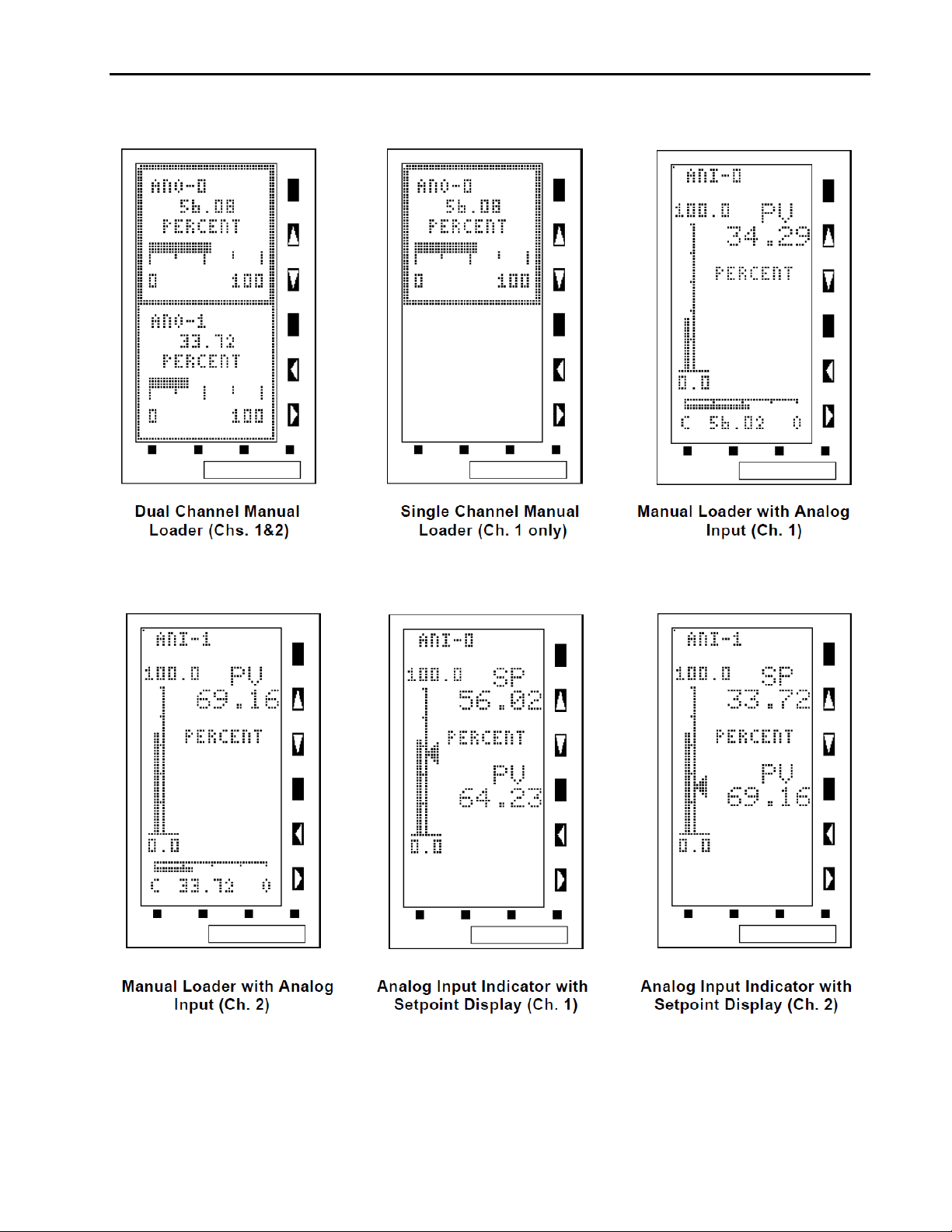
A suite of six operator displays is used to monitor the two input process variables and the two manually
controlled current outputs. The displays are a mix of dynamic bar graphs that include:
Dual Channel Manual Loader Display (Channels 1&2)
Single Channel Manual
Loader Display (Channel 1 only)
Two Manual Loader with Analog Input Displays (Channel 1 and Channel 2)
Two Analog Input Indicator with Setpoint Displays (Channel 1 and Channel 2)
Presentation order of the six operator displays is configurable. The operator displays are paged forward or
back, in the order configured, by pressing the F2 (page forward) or the F1 (page back) push button on the
horizontal keypad of the instrument. The operator display suite is illustrated in Figure 1-1 and the instrument
horizontal keypad is identified in Figure 1-2.
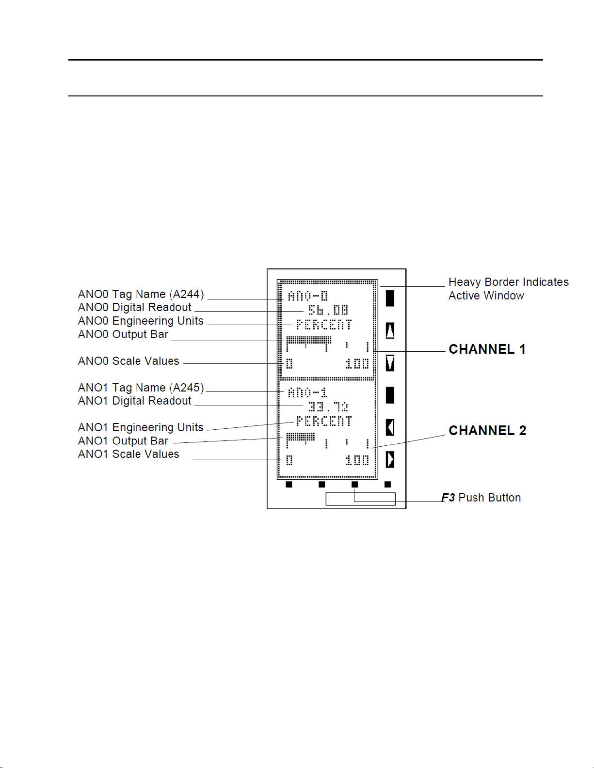
Dual Channel Manual Loader Display (Channels 1&2) - both channel outputs are presented as horizontal
bar graphs with tag names and digital readouts of the output percentage. Channel 1 (Analog Output 0 [ANO0]) occupies the upper half of the display and channel two (Analog Output 1 [ANO-1]) occupies the lower half
of the display. A thick border around the perimeter of the upper or lower display half indicates a selected
channel for manual output control. The thick border alternately appears on the upper or lower display halves
each time the 3 push button is pressed. This display focuses attention on the channel 1 and 2 outputs.
Single Channel Manual Loader Display (Channel 1 only) - channel 1 (ANO-0) output is presented as a
horizontal bar graph with a tag name and digital readout of the output percentage. It has a permanent thick
border to indicate selection for manual output control. This display applies when a single output is required
and focuses attention on that output.
Manual Loader with Analog Input Displays (Channel 1 and Channel 2) - two displays, one for each
channel. Each display has a vertical bar graph for analog input process variable (PV) indication and a
horizontal bar graph for analog output manual control indication. The vertical bar graph has a 50 segment
axis and the horizontal bar graph has a 40 segment axis. Also, the vertical axis has a numeric range (zero
and span) and the horizontal axis has the forward/reverse valve indicators (C for close, O for open). An input
channel tag name appears in the upper left corner of the display. A digital readout with measured units for the
analog input channel appears under the letters PV in the upper half of the display. A digital readout for the
analog output channel appears under the horizontal bar graph. These two displays are in standard MicroMod
MICRO-DCI format.
Analog Input Indicator with Setpoint Displays (Channel 1 and Channel 2) - two displays, one for each
channel. Each display has a vertical bar graph for analog input process variable (PV) indication and a setpoint
(SP) arrowhead for analog output manual control indication. The vertical bar graph appears on the left side,
parallel to a 50 segment vertical axis. The setpoint arrowhead appears on the right side of the vertical axis.
1
Page 6
53ML5100B Manual Loader
INSTRUCTION MANUAL
vertical axis. Also, the vertical axis has a numeric range (zero and span). An input channel tag name appears
in the upper left corner of the display. A digital readout for the analog output channel appears under the
SP in the upper half of the display. The analog input measured units tag appears in the middle of the
letters
display and beneath it a digital readout appears under the letters PV. These two displays provide quick
recognition of the output level relative to the process variable.
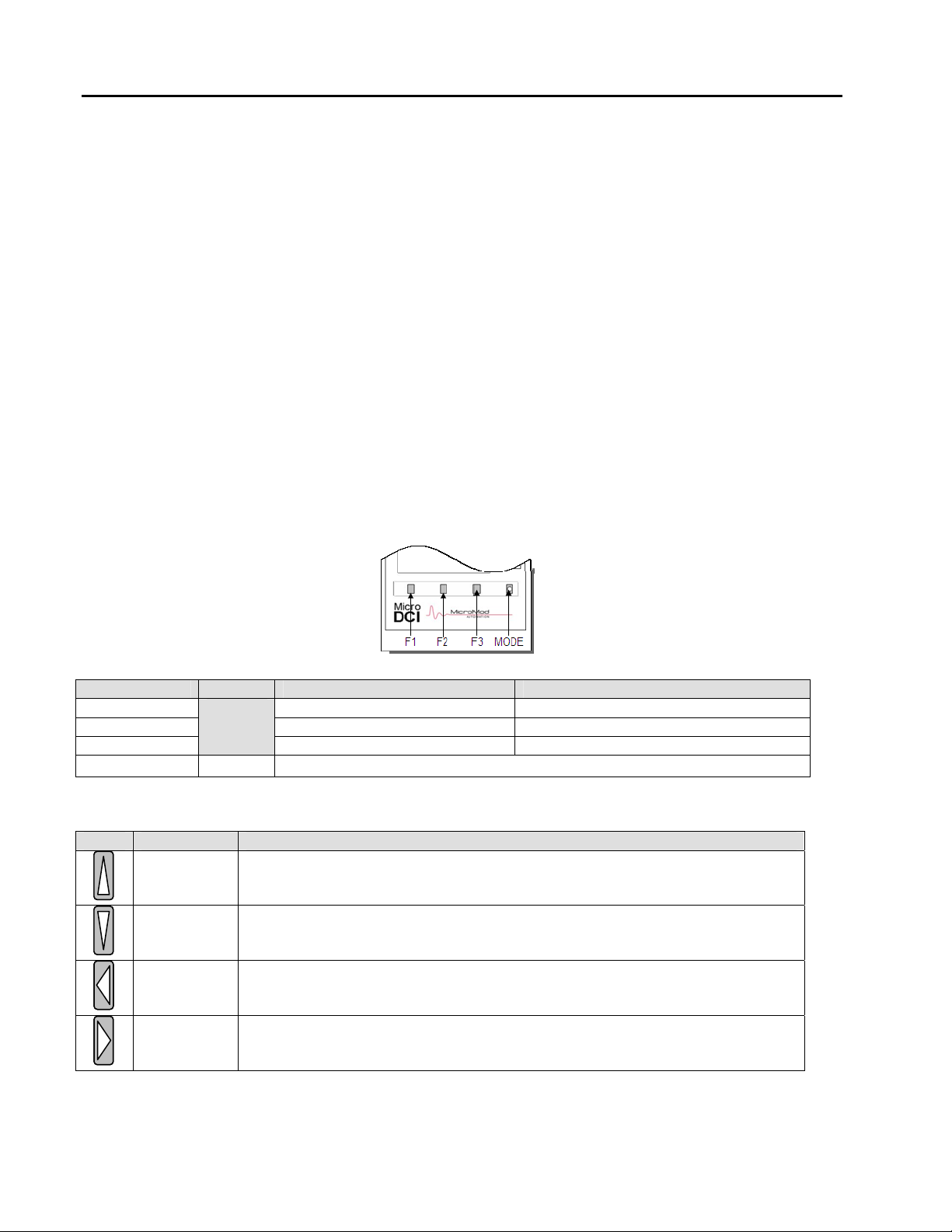
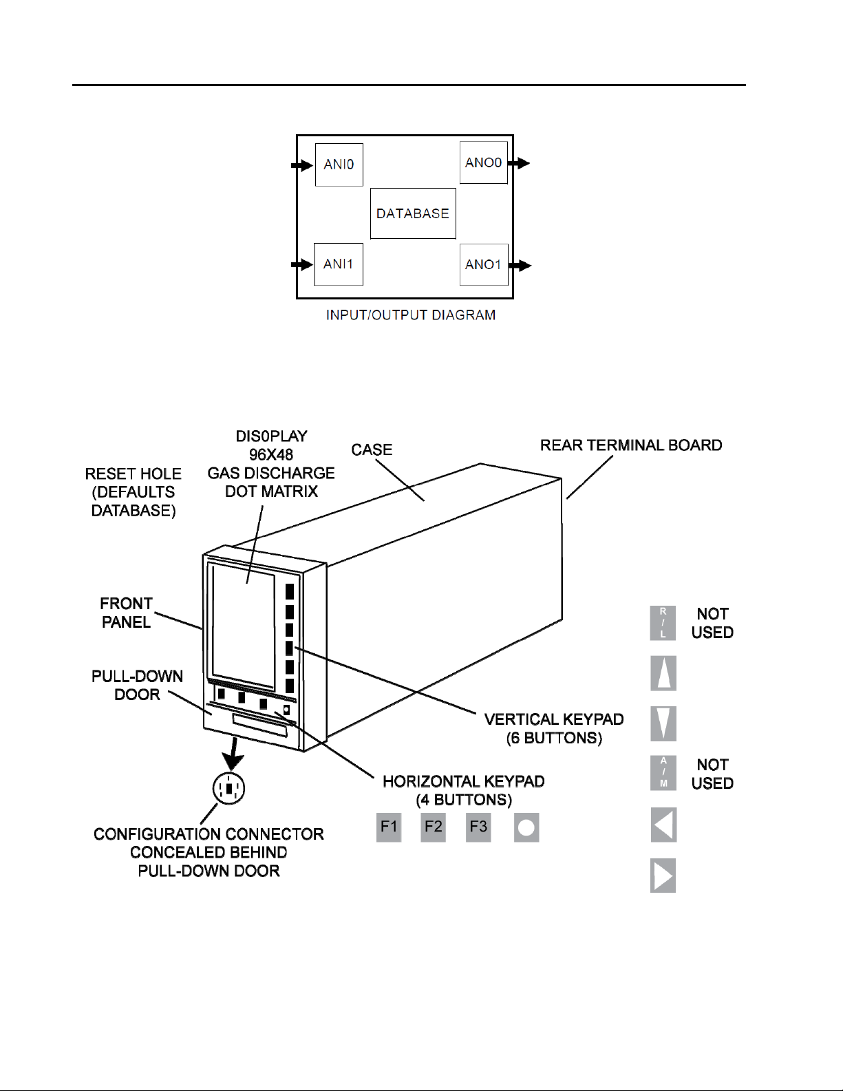
As shown in Figure 1-2, the Manual Loading Station contains a graphical dot matrix display; horizontal and
vertical keypads; a MINI-DIN configuration port connector concealed behind the front panel pull-down door;
terminals for signal input/output wiring and power wiring; and a compact instrument case that protects the
instrument main printed circuit board and internal power supply.
The display is a 96 X 48 gas discharge dot matrix, contrasted orange-on-black to enhance visibility and ease
of reading. The intensity is a range selectable entry from 0 to 7, with 0 being the brightest setting (see Table
4-6).
To the right of the display is the vertical keypad and directly beneath the display is the horizontal keypad.
Both keypads have functioning push buttons that are dependent on the instrument mode of operation which
can be either operator mode or engineering mode. Mode selection is made with the Mode ( z) push button
on the horizontal keypad. Engineering mode is entered to make the necessary selections for the operator
displays; otherwise, the instrument is left in operator mode for process applications. Both keypads are
described as follows:
Horizontal Keypad
Push Button Title Operator Mode Engineering Mode
F1
F2
F3
Title Engineering Mode
Ascending
Character
Select
Descending
Charact
Select
Decrease
Output/
Shift Left
Decrease
Output/Shift
Right
Mode Operator/Engineering mode select
er
Page back to previous display. Back to previous entry line function.
Page forward to next display. Pages the configure/display functions.
xecutes an enter or display function. Moves Quad Bargraph pointer. E
Vertical Keypad
For engineering mode only - displays one character at a time in ascending
alphanumeric order; is released when the desired c
appears on the engineering mode data entry line.
For engineering mode only - displays one character at a time in descending
alphanumeric order; is released when the desired c
appears on the engineering mode data entry line.
In operator mode - decreases the selected channel analog output.
In engineering mode - shifts the selected character one position left on the
engineering mode data entry line each time it is pressed.
In operator mode - it increases the selected channel analog output.
In engineering mode - it shifts the characters on the engineer
entry line one character position right each time it is pressed.
haracter, number, or symbol
haracter, number, or symbol
ing mode data
2
Page 7
53ML5100B Manual Loader
INSTRUCTION MANUAL
Figure 1-1. Manual Loading Station Operator Displays
3
Page 8
53ML5100B Manual Loader
INSTRUCTION MANUAL
4
Figure 1-2. Manual Loading Station Illustrated Overview
Page 9

53ML5100B Manual Loader
INSTRUCTION MANUAL
Setup of the 53ML5100 can be done using the buttons on the horizontal and vertical keypads. It can also be
done via the MicroTools configuration software package. Directly beneath the horizontal keypad and
concealed behind the front panel pull-down door is the RS-232 Configuration Port which accept the
configuration cable that provides interface between the instrument and MicroTools running on a personal
computer. The configuration functions within MicroTools is limited to loaded functions of the 53ML5100
Manual Loading Station described in this manual.
The internal power supply provides power to the main board and output power for transmitters (24-26 V dc,
80 mA total available output for instrument and transmitters).
A simplified input/output diagram of the Manual Loading Station is provided in the upper portion of Figure 1-2.
As illustrated in the figure, the instrument can accept two Analog Input signals (ANI0 and ANI1 ) which are
digitized as operands for firmware interpretation and displayed as process variables. Each ANI has a square
root extractor and can accept linear or squared signals of 0-20 mA (0-5 V) or 4-20 mA (1-5 V). The instrument
also provides two Analog Output signals (ANO0 and ANO1) that can be individually selected and manually
controlled using the front panel push buttons.
All of the selectable entries for the Manual Loading Station are parameter entries to the database.
The database is subdivided into modules composed of datapoints that are accessed by the instruction code
as the instrument performs its functions. The database allows instrument functionality to be refined to specific
process applications, as display attributes can be altered and input/output signal characteristics can be
defined. A datapoint location is represented as an alphanumeric address, such as L472, which is the 0-20 mA
Output select for ANO0. (When L472 is configured with a 0, the ANO0 output range is 4-20 mA; when L472 is
configured with a 1, the ANO0 output range is 0-20 mA.) Datapoints are specified parenthetically in the
illustration call-outs of Section 3 where the displays are described in detail. There are also illustrated
procedures provided in Section 3 that show how a datapoint is displayed and configured. Definitions for all of
the Manual Loading Station datapoints are provided in Section 4 and listed in alphanumeric order in Appendix
A.
5
Page 10

53ML5100B Manual Loader
INSTRUCTION MANUAL
1.2 Model Number Breakdown
53ML51 __ __ B 2 1 A A A
Base Instrument
Power Requirements
1 - AC (120/240V)
2 - DC (24V)
Functional Requirements
1 - Standard
2 - Standard with Factory
Configuration
Design Level
Enclosure Type
DIN 72 x 144 mm bezel
Main Rear Terminal Requirement
Standard
Chassis
Standard
Safety Classification
General Purpose
Conformal Coating
Standard
6
Page 11

53ML5100B Manual Loader
INSTRUCTION MANUAL
1.3 Specifications
Item Specification(s)
Power
Range (as specified in model number) 22 - 26 V dc
Power Consumption (ac/dc operation)
Internal Power Supply:
Available Power Output for Transmitters
Output Ripple 200 mV p-p maximum
Analog Input (ANI0 & 1) Signals (all analog in-puts are referenced to signal common)
Quantity 2 (ANI0 & ANI1)
Signal Range 0 -5 V dc or 1 -5 V dc (0 -20 mA and 4 -20 mA dc respectively).
Input Impedance 1 megohm minimum for voltage inputs; value of ranging resistor for
Measurement Accuracy ± 0.1% of span
Analog Output (ANO0) Signal (is referenced to power common)
Quantity 1 (ANO0)
Signal Range 0 -20 mA dc (4 -20 mA dc typically)
Load Range 0 - 750 ohms
Accuracy ± 0.2% of span
Sampling and Update Attributes
Program Scan Rate 0.05 seconds
Analog Input Signal Sampling Rate 0.05 seconds
Contact Input Signal Sampling Rate 0.05 seconds
Display Update 0.10 seconds
Output Signal Update 0.05 seconds
108 - 132 V rms
216 - 264 V rms
50/60 Hz
36 VA maximum
25 V dc ± 1 V dc @ 80 mA maximum, short circuit protected.
NOTE: The rear terminal board has the appropriate resistors for
ANI0 and ANI1.
current signals.
7
Page 12

53ML5100B Manual Loader
INSTRUCTION MANUAL
Item Specification(s)
Environmental Characteristics
Controlled Environment Enclosed temperature controlled location (Class A and B per ISA-
Ambient Temperature Limits 4 -52°C (40 - 125°F)
Relative Humidity Limits 10 - 90% maximum
Temperature Effects on Accuracy ± 0.28% per 28°C (50°F) change from reference temperature 25°C
Transient Immunity (all circuits) ANSI C37.90a - 1974/IEEE Std 472-974: Ring Wave: 1.5 MHz, 3 kV,
EMI Susceptibility SAMA PMC 33.1-1978: Class 3-abc: no effect at 30 V/m, at 27, 146,
Enclosure Classification/Environment Panel Mounted Equipment: No enclosure rating. Designed to be
Shock 0.5g
Vibration SAMA PMC 31.1-1978; point-to-point constant displacement 0.05 in.
Drop and Topple SAMA PMC 31.1-1978; Tilt 30 degrees from horizontal and fall freely
Safety Classification General Purpose: Complies with ANSI/ISA S82.01-1988, Safety
Physical Characteristics
Material of Construction:
Case Steel, black enamel
Circuit Boards Glass epoxy
Bezel ULTEM 1000 (Polyethermide Resin) Flammability-UL94 5V
Dimensions 2.844W x 5.656H x 12.906L (inches) 73W x 144H x 329L (mm)
Flush Panel Mounting 0.125 inch - 1 inch thickness (3.2 mm - 25.4 mm)
Electrical Connections Screw type terminal block at rear of casework
Weight 5 lbs (2.3 kg)
Front Panel Display 96 x 48 dot addressable
Front Panel Push Buttons 10 membrane type switches
S71.01 1985)
(77°F)
60 pulses/s for 2.0 s
and 446 MHz
installed in a user provided panel or enclosure.
Rated for installation in a Pollution Degree 2 location per U.L. 5081989/Controlled Environment per CSA C22.2 No. 142-M1987. An
indoor, temperature controlled location (Control Room or Shop Floor)
where normally, only non-conductive pollution occurs; however,
temporary conductivity caused by condensation may be expected.
Location in environments more severe than those stated requires
supplementary protection
(1.27 mm), 5 -14 Hz: 0.5 g, 14 - 200 Hz.
to a hard surface, all sides, front and back.
Standard for Electrical and Electronic Test Measuring, Controlling and
Related Equipment; General Requirements and S82.03-1988 Safety
Standard for Electrical and Electronic Test, Measuring, Controlling and
Related Equipment; Electrical and Electronic Process Measurement
and Control Equipment.
FM Approved: Nonincendive for Class 1, Division 2, Groups A, B, C, &
D, Temperature Code T3C 160 ° C.
8
Page 13

53ML5100B Manual Loader
INSTRUCTION MANUAL
2 INSTALLATION
2.1 Inspection
A list of all items in the shipment is attached to the shipping container. Inspect the equipment upon arrival for
damage that may have occurred during shipment. All damage claims should be reported to the responsible
shipping agent before installation is attempted. If damage is such that faulty operation is likely to result, the
MicroMod Customer Service Department should be notified.
Inspect the packing material before discarding it as a precaution to prevent loosing mounting hardware or
special instructions that may have been included with the shipment. Normal care in the handling and
installation of this equipment will contribute toward its satisfactory performance.
2.2 Location
The 53ML5100 is supplied with an enclosure designed specifically for indoor mounting. The installation site
selected should be dry, well lighted, and vibration free. The ambient temperature should be stable and
maintained within the specified minimum and maximum temperature limits listed in the Section 1,
specifications of this Instruction Bulletin.
The instrument can be supplied for use with a 24 V dc supply or 120, 220 and 240 V ac line service.
Instrument power requirements are given on the instrument data tag.
2.3 Mounting
2.3.1 General
It is normally not necessary to open the instrument case during installation. If the instrument must be removed
from the case, refer to Section 5 for details. Incorrect procedures may damage the instrument.
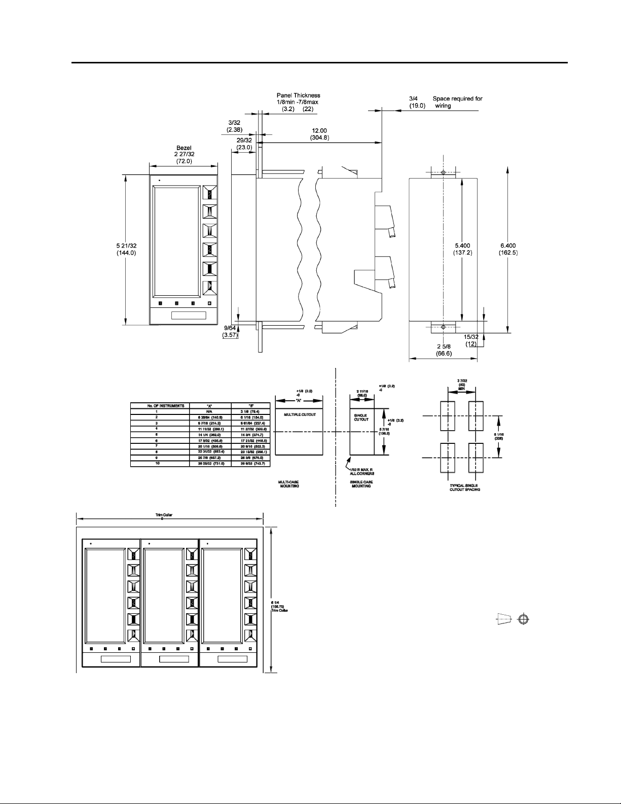
The instrument can be flush panel mounted, either as a single unit or side by side. Appropriate mounting
hardware is supplied. Outline dimensions and panel cut-out requirements for case mounting are shown in
Figure 2-1.
The dimensions given for spacing between instruments were selected on the basis of 1/8" thick panel
strength. Panel strength must be considered when multiple case mounting is required. As the panel cut-out
becomes longer it may be necessary to install supporting members. Because the panel area between
instrument rows becomes weaker as the cut-out becomes longer to the point where the panel offers very little
support. It is recommended that the 9 inch minimum center line dimension between horizontally mounted
rows be increased as the number of units increases, or that the panel strip be stiffened.
The rear of the instrument case must be supported to prevent panel distortion. Mount an angle iron or similar
member along the bottom of the cases as indicated in Figure 2-2. If the panel is to be moved the instrument
cases must be tied down to prevent damage.
If multiple mounted instruments are installed in a panel that tilts back, it may be necessary to support the
instruments so the panel does not sag. The downward weight should be supported by additional panel
supports and/or by increasing panel thickness.
9
Page 14

53ML5100B Manual Loader
INSTRUCTION MANUAL
2.3.2 Mounting Procedure
For single and multiple case mounting the instruments are furnished with a trim collar (mounting frame).
Figure 2-2 illustrates the installation and use of the trim collar (mounting frame). Trim collars (mounting
frames) are available in various sizes and are supplied to conform with the particular panel cut-out.
NOTE: Mounting brackets and trim collars (mounting frames) are packaged separately. Check the
shipment carefully to prevent loss of mounting hardware.
To install single or multiple mounted instruments in a prepared panel cut-out, proceed as follows:
1. Remove the through-case shipping bolt.
2. Slip the trim collar (mounting frame) over the rear of the case and slide it forward to the front of the
case.
3. Slide the instrument case through the panel opening.
a. Single mounting case - support the weight of the case and attach the top and bottom
mounting brackets. Tighten the bracket screws.
b. Multiple mounted cases - spacer bars and self-adhesive pads must be used between the
cases, as shown in Figure 2-3. Start the installation from the right (when facing the panel),
installing the spacers as each case is added. Also, as each case is positioned in place, install
and tighten the top and bottom mounting brackets. Each case must be tight against the
previous case.
NOTE: Spacers are not required on the outside of the right and left cases.
10
Page 15
53ML5100B Manual Loader
INSTRUCTION MANUAL
NOTES:
1. DIMENSIONS ARE IN INCHES. DIMENSIONS IN BRACKETS (
) ARE IN MILLIMIETERS.
2. DIMENSIONS GUARANTEED ON CERTIFIED PRINTS ONLY.
3. CASE MOUNTING HARDWARE SUPPLIED UNLESS
OTHERWISE SPECIFIED.
4. THIS DRAWING IS THIRD-ANGLE PROJECTION AS SHOWN
5. UNLESS OTHERWISE INDICATED ALL TOLERANCES ARE ±
1/16 (1.6)
Figure 2.1 Outline Dimensions & Panel Cut-out Requirements
11
Page 16

53ML5100B Manual Loader
INSTRUCTION MANUAL
Figure 2-2. Single or Multiple Panel Mounting
Figure 2-3. Intercase Spacing
12
Page 17

53ML5100B Manual Loader
INSTRUCTION MANUAL
2.4 Power & Signal Wiring
PREPARATORY: The 53ML5100 can be configured for one to four analog inputs (ANI0-3), one analog
output (ANO0), two control contact inputs (CCI0 and 1), two control contact outputs (CCO0 and 1) and
Datalink network interconnectivity. Therefore, prior to making electrical connections, the particular instrument
configuration should be determined with all assigned inputs and outputs identified to assure proper signal
routing.
Provisions for electrical interconnections are located at the rear of the instrument case. Under ideal conditions
shielded cable may not be required. In noisy locations all system input, output and power wiring should be
enclosed in electrical conduit. System interconnection cables (except for power cables) should be fabricated
from 2-wire shielded signal cable. Signal transmission distance should not exceed the limit specified for the
particular transmitter (refer to applicable technical literature provided for the respective device). Polarity must
be observed when connecting the remote transmitters to the instrument.
The instrument has a vertically mounted terminal strip (TB1) for signal interconnections and a horizontally
mounted terminal strip (TB2) for power wiring. Both terminal strips are located at the rear terminal board of
the instrument case.
SNAP-OUT TERMINAL CONNECTORS
Both terminal strips, TB1 and TB2, have removable plug-in connectors. The upper connector for TB1 has
screw lugs 1 through 12 and the lower connector has screw lugs 13 through 22. All of the screw lugs are on a
single connector for TB2. To remove a signal connector, grasp it securely on both sides with the thumb and
forefinger, rock it gently from top to bottom (not side to side) and pull it straight out. To remove the power
connector, grasp the sides firmly with the thumb and forefinger, rock it gently from side to side and pull
straight out.
NOTE: The screw lugs on the back of the instrument are designed for 12 – 24 AWG wire. It is
important that the wire be stripped to expose 1/2 inch of conductor before installation.
WARNING! Instruments that are powered from an ac line service constitute a potential
electric shock hazard to the user. Make certain that these system ac power lines are
disconnected from the operating branch circuit before attempting electrical interconnections.
13
Page 18

53ML5100B Manual Loader
INSTRUCTION MANUAL
14
Figure 2-4. Controller Rear Power and Signal Terminal Boards
Page 19

53ML5100B Manual Loader
INSTRUCTION MANUAL
15
Page 20

53ML5100B Manual Loader
INSTRUCTION MANUAL
2.4.1 Power Wiring
Refer to the instrument model number to verify the power input requirements:
53ML511nB21AAA – AC Power
53ML512nB21AAA – DC Power
2.4.1.1 DC Power
Reference Figure 2-4 and connect the remote 24 V dc power supply to the instrument as follows:
1.
Connect (+) input line, via remote SPST switch, to terminal L1.
2. Connect (-) input line to the system bus bar. The bus bar should be connected to a good earth ground
(#8 AWG wire is recommended). Individual wires should be run from the controller Power Common
(PC ) and Signal Common (SC ) terminals to the bus bar. The chassis should be grounded by
connecting terminal G to earth ground.
NOTE: Use of a common bus bar is recommended to minimize potential voltage differences that may
occur as the result of ground current loops, e.g., potential difference between separate signal grounds,
power grounds, etc.
2.4.1.2 AC Power
Reference Figure 2-4 and connect the specified line service (110-120, 220-240 V ac, 50 or 60 Hz) to the
trument as follows:
ins
1. Connect the phase or hot line L, via a remote power disconnect switch or circuit breaker, to terminal
L1.
2. Connect the neutral line N to terminal L2 for 110-120 V ac. Connect the neutral line N to terminal L3
for 220-240 V ac.
3. Connect Power Common to a good earth ground (#12 AWG wire is recommended). The instrument
case should be grounded by connecting terminal G to earth ground at the source of supply
(green/green-yellow ground).
All supply connections include surge protection rated at 275 V ac normal mode.
NOTE: To minimize possible interference, ac power wiring should be routed away from signal wiring.
2.4.2 Field Signal Wiring
2.4.2.1 Current/Voltage Input to AIN0 and AIN1
When the input signal is from a 4-20 mA current transmitter, a precision 250 ohms (+/-0.1%) resistor is
required. (The resistor tolerance is critical, as the resistor is used to accurately convert the current signal from
the transmitter, which is typically 4-20 mA, to a specified analog input voltage of 1 to 5 V dc). The back of the
rear terminal board has the appropriate resistors (R1 and R2, respectively) for ANI0 and ANI1.
2.4.2.2 Current Output from ANO0 and ANO1
The 53ML5100 Manual Loading Station provides the capability to manually adjust and display one or two
current outputs. Each output is independently configurable as a 0-20 mA or 4-20 mA signal. (The
configuration selections for each analog output are provided in Section 4.) Observe the proper polarity when
connecting each analog output to another instrument.
2.5 Factory Set Calibration
Each unit contains individual factory set entries that calibrate the four analog inputs (ANI0 through ANI3) and
analog output (ANO0). There is a calibration sheet supplied with each instrument that should be retained for
future reference when the installation is completed. Reference Section 5.3 for additional information.
2.6 Grounding
Installations are expected to have access to an independent, high quality, noise-free point of earth reference.
The system should be connected by a dedicated, low resistance (less than one ohm) lead wire directly to the
installation’s point of earth reference. This ground reference is referred to as the Instrumentation Ground. If
16
Page 21

53ML5100B Manual Loader
INSTRUCTION MANUAL
an instrumentation ground reference does not exist in the installation, an earth ground electrode should be
established with an independent grounding rod or ground grid mesh.
17
Page 22

53ML5100B Manual Loader
INSTRUCTION MANUAL
18
Page 23
53ML5100B Manual Loader
INSTRUCTION MANUAL
3 DISPLAYS AND PUSH BUTTONS
This section provides illustrations with item call-outs of the six operator displays and engineering mode
overlays. Where applicable, datapoints are identified parenthetically with the display item call-outs. The
datapoints are defined in Section 4. The front panel push button definitions are repeated in this section from
Section 1, because they are used in the engineering mode display overlay examples to enter a key password,
display a datapoint, and alter a datapoint.
3.1 Operator Displays
Display 1 - Dual Channel Manual Loader (Chs. 1&2) is illustrated twice: in Figures 3-1 and 3-2 to show
channel 1 selected for output control and channel 2 selected for output control using the F3 push button. The
remaining five operator displays are illustrated in Figures 3-3 through 3-7 as follows: Figure 3-3, Display 2 Single Channel Manual Loader (Ch. 1 only); Figure 3-4, Display 3 -Manual Loader with Analog Input (Ch. 1);
Figure 3-5, Display 4 - Manual Loader with Analog Input (Ch. 2); Figure 3-6, Display 5 - Analog Input Indicator
with Setpoint Display (Ch. 1); and Figure 3-7, Display 6 - Analog Input Indicator with Setpoint Display (Ch. 2).
Figure 3-1. Display 1 - Dual Channel Manual Loader (Chs.
1&2)
19
Page 24

53ML5100B Manual Loader
INSTRUCTION MANUAL
Fig 3-2. Display 1 - Dual Channel Manual Loader (Chs. 1 & 2)
Showing Channel 2 Selected Using the F3 Push Button
20
Figure 3-3. Display 2 - Single Channel Manual Loader (Ch. 1 only)
Page 25

53ML5100B Manual Loader
INSTRUCTION MANUAL
Figure 3-4. Display 3 - Manual Loader with Analog Input (Ch. 1)
Figure 3-5. Display 4 - Manual Loader with Analog Input (Ch. 2
21
Page 26

53ML5100B Manual Loader
INSTRUCTION MANUAL
Figure 3-6. Display 5 - Analog Input Indicator with Setpoint Display (Ch. 1)
Figure 3-6. Display 6 - Analog Input Indicator with Setpoint Display (Ch. 2)
22
Page 27

53ML5100B Manual Loader
INSTRUCTION MANUAL
3.2 Front Panel Pushbuttons
The front panel push buttons are repeated here from Section 1 because they are used in the engineering
mode display overlay examples to enter a key password, display a datapoint, and alter a datapoint.
To the right of the display is the vertical keypad and directly beneath the display is the horizontal keypad.
Both keypads have functioning push buttons that are dependent on the instrument mode of operation which
can be either operator mode or engineering mode. Mode selection is made with the Mode () push button
on the horizontal keypad. Engineering mode is entered to make the necessary selections for the operator
displays and to configure the Datalink port; otherwise, the instrument is left in operator mode for process
applications. The vertical keypad is dedicated only to engineering mode functions and has no effect in
operator mode. Both keypads are described as follows:
Horizontal Keypad
Push Button Title Operator Mode Engineering Mode
F1
F2
F3
Title Engineering Mode
Ascending
Character
Select
Descending
Character
Select
Shift Left
Shift Right
Mode Operator/Engineering mode select; Alarm reset.
Page back to previous display. Back to previous entry line function.
Page forward to next display. Pages the configure/display functions.
Selects analog output 0 or 1 as
indicated by thick display
border.
Vertical Keypad
Displays one character at a time in ascending alphanumeric order; is released
when the desired character, number, or symbol appears on the engineering
mode data entry line.
Displays one character at a time in descending alphanumeric order; is released
when the desired character, number, or symbol appears on the engineering
mode data entry line.
Shifts selected character one position left on the engineering mode data entry
line each time this push button is pressed.
Shifts characters on engineering mode data entry line one character position
right each time this push button is pressed.
Executes enter or display function.
23
Page 28

53ML5100B Manual Loader
INSTRUCTION MANUAL
3.3 Engineering Mode Overlays
The engineering mode overlays are used to make the necessary parameter entry selections for the operator
displays and to configure the Datalink communications port. The entries are made to addressed datapoints
via the overlay single edit line at the bottom of the display. It should be noted that engineering mode has a 20
second timeout if it is accessed and its functions (e.g., configure or display) are not used.
3.3.1 Responding to the Prompt: KEY?
When the password prompt KEY? appears, it indicates a password was set in the MicroTools software. The
password can not be set via the front panel push buttons.
A password key is a maximum of 10 numeric characters (numbers 0-9 only). It does not impede display
functions in engineering mode but must be unlocked to perform configuration functions. A password key is
NOT SET FOR NEW INSTRUMENTS from the factory; therefore, if it is set, it must have been done locally.
The password must first be obtained from the originator before the procedure in Table 3-1 can be used to
access the engineering mode configuration function capabilities.
Table 3-1. Entering a Key Password
Step Press
Once
1
Shift
Result
Press to
Locate
Target
Char.
Result
Puts instrument in engineering mode.
2
3
F3
4
If DISPLAY appears instead of CONFIGURE, press 2.
Displays password query: KEY?
2
Puts first password number on entry line: KEY? .2.
5
.2Δ
6
7 Repeat step 6 until all of the password characters are entered.
.22Δ
2
2
8
F3
NOTE: Δ indicates Space
Shifts 2 and puts second password number on entry
line: KEY? .22.
Shifts 22 and puts third password number on entry
line: KEY? .222.
Enters the password key and displays the entry line:
POINT . The engineering mode configuration
function is now accessible for use.
24
Page 29

53ML5100B Manual Loader
INSTRUCTION MANUAL
Figure 3-8. Engineering Mode Key Password Prompts
25
Page 30

53ML5100B Manual Loader
INSTRUCTION MANUAL
3.3.2 Displaying a Datapoint
The following procedure illustrates how to display the contents of datapoint C175, which is ANI2 Alarm Limit
1. Figure 3-9 contains supporting illustrations for the display procedure described in Table 3-2.
Table 3-2. Procedure to Display a Datapoint
Step Press
Once
1
2
Shift
Result
Press to
Locate
If DISPLAY does not appear, press F2.
Target
Char.
Result
Puts instrument in engineering mode.
.CΔ
.C1Δ
C
1
7
Displays entry line: POINT
Puts B on entry line: POINT .B.
Shifts B and puts 1 on entry line:
POINT .B1.
Shifts B1 and puts 2 on entry line:
POINT .B12.
Enters address to display datapoint contents.
The address with the contents are displayed as
follows: B12 4
Returns instrument to operator mode.
3
4
5
6
7 F3
8
F3
NOTE: Δ indicates Space. Also, B12 can be entered for B012, as datapoints 99 or less for all of the
data types (e.g., A, B, C, H, and L - see Table 4-1) do not require leading zeros.
26
Figure 3-9. Displaying a Datapoint
Page 31

53ML5100B Manual Loader
INSTRUCTION MANUAL
3.3.3 Altering a Datapoint
The procedure in Table 3-3 illustrates how to alter the contents of datapoint C175, which
is ANI2 Alarm Limit 1, from 80 to 90. Figure 3-10 is provided to show the maximum input
character length for the engineering mode edit line. The edit line can accept ten
characters. The full ten character field is used primarily for the A type datapoint text
strings (tag names). Reference Table 4-1 in Section 4 for information about the datapoint
types. Note that in Figure 3-10, the PO is residual from the prompt POINT and that the
character field string starts with 1 and ends with 0 (underlined in the figure) to illustrate 10
characters.
Figure 3-10. Entry Line
Ten Character Field
Table 3-3. Procedure to Alter a Datapoint
Step Press
Once
1
2
3 F3 Displays entry line: POINT
4
5
6
7
8 F3
9
Hold
10
11
12 F3
13
NOTE:
Shift
Result
Puts instrument in engineering mode.
.CΔ
.C1Δ
.C17Δ
locator
.9Δ
Δ indicates Space
•
Press to
Locate
If CONFIGURE does not appear, press F2.
Target
Char.
C
1
7
5
9
0
Result
Puts C on entry line: POINT .C
Shifts C and puts 1 on entry line:
POINT .C1
Shifts C1 and puts 7 on entry line:
POINT .C17
Shifts C17 and puts 5 on entry line:
POINT .C175
Enters address to display datapoint contents.
The address with the contents are displayed as
follows: C175 80.0000
C175 contents shifted right; only the locator
point remains on the entry line: C175
Puts 9 on entry line: C175 .9
Shifts 9 and puts 0 on entry line:
C175 .90
Enters the value 90 in datapoint C175
Returns instrument to operator mode.
27
Page 32

53ML5100B Manual Loader
INSTRUCTION MANUAL
28
Page 33

53ML5100B Manual Loader
INSTRUCTION MANUAL
4 CONFIGURATION PARAMETERS
The configuration parameters provide the latitude to define the instrument’s personality attributes, so that
while still functioning within its designed specifications, it can perform application requirements with greater
refinement. Typical configuration parameters are the instrument’s indicator zero point and span, the display
tag names, engineering units of the displayed process value, and alarm limits, etc. IT IS NOT NECESSARY
TO DEFINE ALL OF THE CONFIGURATION PARAMETERS, as commonly used preset values may not have
to be altered and certain parameter selections eliminate others.
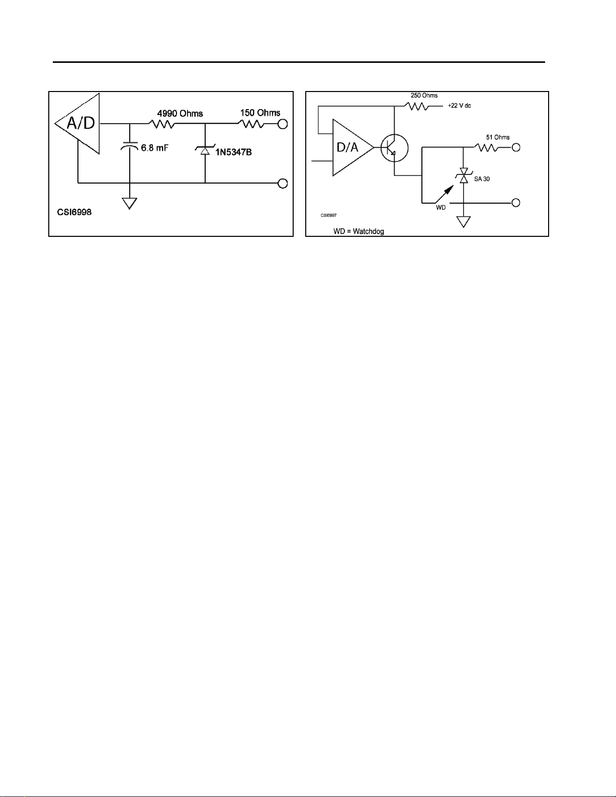
Although all resident in a memory database as datapoints, the configuration parameters are clustered into
modular groups that may have specific hardware identities (e.g., the ANI0&1 and ANO0&1 circuits illustrated
in Figures 4-1 and 4-2), or may represent software controlled functions that are not specific to any one
hardware element.
4.1 Datapoint Types
A parameter can be any one of five data types. Each data type represents a specific data format:
integers, alphanumeric text strings, etc. A database module containing multiple parameters can
have a mix of data types. The data types are defined in Table 4-1 as follows:
Table 4-1. Datapoint Types
Type Byte
Size
L 1 Bit Represents a single binary bit that can have the value of 0 or 1.
B 1 Represents a positive integer with values from 0 to 255.
C 3 Represents a real analog (floating point) value that has a resolution of one part in
H 5 Represents a high precision analog (floating point) value that has a resolution of
A 10 Represents a text string that can be 10 characters long.
4.2 Factory Standard Calibration
The instrument is shipped from the factory configured with all parameters set to the default values. The
default values are listed in the parameter tables under the heading Default. The gray-tone shading in a
default cell of a parameter indicates the contents of the datapoint are left unchanged after the database is
returned to the default condition using the procedure described in Section 5.5. Examples of datapoints
unaltered by default are the Calibrate Zero and Calibrate Span parameters which are factory set.
4.3 Configuring the Database Modules
The datapoints in the database modules must be changed to reflect required alterations in the factory
standard configuration or when the instrument is re-configured. There are generally two datapoint parameter
types contained in the four database modules. The four database modules are described in Table 4-2.
Although it is not an absolute criterion, it is assumed the modules will be configured in the table Item order.
Table 4-2 is also a pointer to the descriptions of the database modules; the descriptions are presented
as Tables 4-3 through 4-10. (The gray tone shading in the default cell of a datapoint indicates the datapoint
contents are left unchanged after default. See Section 5.5 for the default procedure.)
Format
32,768 (15 bits) and a dynamic range of ± 10
one part in 2 billion (31 bits) and a dynamic range of ± 10
38 .
38 .
29
Page 34

53ML5100B Manual Loader
INSTRUCTION MANUAL
Table 4-2. Database Modules
Item Title Purpose See
Table
1 Analog Input Module This module is used to configure the voltage/current input
signals (e.g., 0-5 volts [0-20 mA], 1-5 volts [4-20 mA]) and
how the two input signals are interpreted (linear or square
root representation, with or without smoothing). It is also
used to configure the vertical axis range (zero and span) on
the display.
2
Analog Output Module
3 Display Module This module is used to define the number of displays (six
4 System Module This module is used to set the instrument tag name and the
The primary purpose of this module is to select and set the
0 - 20 mA or 4 -20 mA output signals for ANO0 and ANO1.
maximum) and to set the display order presentation of the
operator displays.
4-10
display brightness.
4-3
4-4
4-5
30
Page 35

53ML5100B Manual Loader
INSTRUCTION MANUAL
Table 4-3. Analog Input (ANI) Module
Purpose: This module is used to configure input voltage characteristics (e.g., input voltage range), and how the
input signals are interpreted (linear or square root representation).
Title Symbol ANI Datapoint Default Attribute
Analog
Input
(Display
Only)
ANI0
ANI1
ANI0
ANI1
H000
H001
0
0
This is the value in engineering units of the
measured input after all signal conditioning has
been applied.
Engineering
Span
Engineering
Zero
Digital Filter
Index
0 - 5 V Input
Square Root
Signal
Calibrate
Zero
Calibrate
Span
Tag Name
SPAN0
SPAN1
ZERO0
ZERO1
DFILT0
DFILT1
NOBIAS0
NOBIAS1
SQRT0
SQRT1
CIZ0
CIZ1
CIZ2
CIZ3
CIS0
CIS1
AITAG0
AITAG1
ANI0
ANI1
ANI0
ANI1
ANI0
ANI1
ANI0
ANI1
ANI0
ANI1
ANI0
ANI1
ANI2
ANI3
ANI0
ANI1
ANI0
ANI1
ANI2
ANI3
C256
C257
C276
C277
B269
B270
L416
L417
L440
L441
B263
B264
B265
B266
C296
C297
A224
A225
A226
A227
100
100
0
0
3
3
0
0
0
0
ANI-0
ANI-1
ANI-2
ANI-3
This determines the upper range the analog
input represents in engineering units. The
upper range value equals Engineering Zero
plus Engineering Span.
This is the lower range value.
This controls a first order filter that is applied
to the input signal. The time constant is
entered as an index value as follows:
0 -No Smoothing (no effect)
1 -0.05 s
2 - 0.1 s
3 - 0.3 s
4 - 0.7 s
5 - 1.5 s
Setting this parameter to 1 indicates the input
range is from 0 -5 volts (0 -20 mA). 0
indicates the input range is from 1 -5 volts (4 20 mA).
When a 0, it indicates the analog input signal
should be interpreted linearly.
When 1, it indicates the analog input signal
should be interpreted as a square root
representation of the value. When square root is
selected, input signals less than 1% (10% input
range) forces the input to its zero value.
This is the calibration zero adjustment. This
parameter is factory set and should not need
adjustment under normal operation.
See Section 5.3 for adjustment.
This is the calibration span adjustment. This
parameter is factory set and should not
need adjustment under normal operation.
See Section 5.3 for adjustment.
an assignable 10 character name for the analog
input (ANI-0, ANI-1, ANI-2, ANI-3).
6 - 3.1 s
7 - 6.3 s
8 -12.7 s
9 -25.5 s
10 -51.1 s
11 - 102 s
12 - 205 s
13 - 410 s
14 - 819 s
15 -1638 s
Engineering
Units
AIEU0
AIEU1
ANI0
ANI1
A298
A299
PERCENT
(ALL)
assignable for units of measure the ANI
represents (e.g., GPM for gallons/minute).
31
Page 36
53ML5100B Manual Loader
INSTRUCTION MANUAL
Figure 4-1. ANI0 & ANI1 Figure 4-2. ANO0 & ANO1
NOTE: These figures are graphical representations of the signal conditioning that occurs on the
instrument main board. They are provided for reference purposes only.
32
Page 37

53ML5100B Manual Loader
INSTRUCTION MANUAL
Table 4-4. Analog Output (ANO) Module
Purpose: The primary purpose of this module is to set the 0 - 20 mA output signal relative to the displayed percent
and to select the analog input signal (ANI0-3) that is to be routed to the analog output (ANO0).
Title Symbol ANO0
Datapoint
Analog Output
(Display Only)
0 -20 mA
Output
Calibrate Zero COZ0
Calibrate
Span
Reverse Valve RSV0
Control Action
Engineering
Units
Tag Name
ANO0
ANO1
OZBASE0
OZBASE1
COZ1
COS0
COS1
RSV1
AOTAG0
AOTAG1
C000
C001
L472
L473
B267
B268
C300
C301
L109
L133
L106
L130
A001
A003
A244
A245
Default Attribute
0
0
0
0
0
0
0
PERCENT
(Both)
ANO0
ANO1
The value in this datapoint represents the percent of
output to be generated by hardware (e.g., 100% output
= 20 mA).
When a 0, the percentage output generates a 4 -20 mA
signal. When set to 1 , the percentage output generates
a 0 -20 mA signal.
These parameters are factory set and should not
need adjustment under normal operation. See Section
5.3 for adjustment.
Positions the forward/reverse valve indicators
(C for close, O for open) beneath the output
horizontal bar graph of each Manual Loader with
Analog Input Display (Channel 1 and Channel
2). When set to a 0, it indicates 20 mA output opens the
valve (C at left end and O at right end of bar graph).
When set to a 1, it indicates 20
mA output closes the valve (O at left end and C
end of bar graph).
When set to a 0, current increases toward 20
mA to open the valve more as the output indicator
increases when the push button is pressed.
When set to a 1, current decreases toward 0 mA
close the valve as the output indicator
the push button is
Assignable for units of measure the ANO
represents (e.g., GPM for gallons per minute).
The assignable 10 character name for for each ANO
(ANO0 and ANO1).
at right
to
increases when
pressed.
33
Page 38

53ML5100B Manual Loader
INSTRUCTION MANUAL
Table 4-5. Display Module
Purpose: This module is used to define the number of displays (six maximum) and to set the display order
presentation of the operator displays. The default settings are for six displays in the order shown in Figure 1-1 and
listed as follows:
1. Dual Channel Manual Loader (Chs. 1&2)
2. Single Channel Manual Loader (Ch. 1)
3. Manual Loader with Analog Input (Ch. 1)
4. Manual Loader with Analog Input (Ch. 2)
5. Analog Input Indicator with Setpoint Display (Ch. 1)
6. Analog Input Indicator with Setpoint Display (Ch. 2). Displays can be listed in any order and less than six can be
specified, for example, for a single channel configuration: B018 = 3 (three displays), B021 = 3, B022 = 5, and B023
= 2. The displays will advance from display number 3, to display number 5, to display number 2 each time the F2
push button is pressed. Pressing the F2 push button a fourth time repeats the cycle with display 3 again.
Datapoint
Title Symbol
Number
of
Displays
Display 1 B021 1
Display 2 B022 2
Display 3 B023 3
Display 4 B024 4
Display 5 B025 5
Display 6 B026 6
MDS B018 6 specifies the total number of operator displays that are presented
Default Attribute
each time the 2 push button is pressed before the cycle repeats
itself beginning with the first display number selected. The
maximum number is 6.
Each datapoint is loaded with a display number from the list above
to set the display presentation order.
34
Page 39

53ML5100B Manual Loader
INSTRUCTION MANUAL
Table 4-6. System Module
Purpose: This module is used to set the instrument tag name and the display brightness.
System
Title Symbol
Module
Datapoint
Default Attribute
Display
Brightness
Index
Model Number
Low (Display
Only)
Model Number
High (Display
Only)
Datalink
Disable
Unit Tag Name TAG A008 ML5100
BRIGHT B012 4
A190 Factory Set
A191 Factory Set
DLD L257 1
This parameter controls the display screen
intensity. A value of 0 is the brightest and a
value of 7 is the dimmest intensity. Normal
viewing setting is 4.
It contains the first ten characters of the model
number.
It contains the last ten characters of the model
number.
This instrument does not have network
capabilities; therefore, the datapoint should be
left at its default value of 1, to indicate no
Datalink capabilities.
An assignable 10 character name for the system
module (53ML5100).
35
Page 40

53ML5100B Manual Loader
INSTRUCTION MANUAL
36
Page 41

53ML5100B Manual Loader
INSTRUCTION MANUAL
5 MAINTENANCE
NOTE: The factory set calibration constants for ANI0-3 and ANO0 are applicable only for the main
printed circuit board supplied in the particular instrument. This data is recorded on a calibration sheet
supplied with the instrument. The data should be retained to facilitate easy field recalibration in the event
one or more of the constants is inadvertently changed.
5.1 Service Approach
This instrument is a microprocessor based device; all mathematical computations, data manipulation, and
sequencing operations are software controlled. After the instrument has been configured, normal operations
are controlled via the front panel push buttons. Because the instrument does not have internal circuitry that
requires field adjustment, diagnostic testing and preventive maintenance are not required.
Generally, when a process malfunction occurs, it usually manifests itself as an instrument problem even
though it might be a defective process variable monitoring device, remote transmitter, or interconnecting
wires. These associated remote devices should be checked before attempting instrument troubleshooting and
repair.
Due to the complexity of microprocessor based instruments, attempting fault finding analysis to integrated
circuits (ICs) on the main printed circuit board (PCB) is not recommended. The ICs are static sensitive and
can be damaged if not properly handled. Also, when test probes are connected, even a momentary short
across several IC pins with a probe tip can damage the IC. Therefore, only trained technicians familiar with
CMOS technology and microprocessor functionality should be permitted to service the equipment.
5.2 Parts Replacement
WARNING: ALWAYS REMOVE POWER BEFORE ATTEMPTING TO INSTALL, DISASSEMBLE,
OR SERVICE ANY OF THE EQUIPMENT. FAILURE TO REMOVE POWER MAY RESULT IN
SERIOUS PERSONAL INJURY AND/OR EQUIPMENT DAMAGE.
Access to internal instrument parts is achieved by removing the front display panel. The front display panel
can be removed by inserting a small screwdriver into the notch at the top center of the display and twisting
the screwdriver to depress the retaining latch. The upper sides of the display are held and pulled forward as
the latch is depressed. The cable at the rear of the front display panel is disconnected from its socket. The
other cable end connects to the main printed circuit board. Replacing the display unit requires reconnecting
the display end of the cable to the new front display panel, inserting the extended portion of the display panel
into the instrument cabinet and latching it in place with a screwdriver.
After the front display panel is removed, the main printed circuit board can be accessed. The main printed
circuit board also has the power supply as well as the microprocessor circuitry. To remove the main PCB, use
its front edge board ejector to pull it free from the rear terminal board slot and carefully slide it from the case.
Disconnect the front display panel flat ribbon cable from the main PCB. The replacement main PCB can now
be installed by connecting the front display panel ribbon cable, sliding the PCB into the instrument case,
seating it into the rear terminal board slot, and installing the front display panel.
The power supply does not have to be removed to replace the fuse. The fuse can be accessed on the power
supply when the main PCB is removed from the instrument. To remove a suspected blown fuse, pry off the
plastic fuse cover cap and pull the fuse from the holder prongs. To install a new fuse, gently snap it into each
end of the holder prongs and push on the cover cap.
Power Supply Fuses
AC Power: 1A, 250 V, Fast Blow Schurter Type 034.3930
DC Power: 3A, 250 V, Slow Blow BEL Type 5TT3
For additional information, contact MicroMod Automation.
37
Page 42

53ML5100B Manual Loader
INSTRUCTION MANUAL
NOTE: When communicating with MicroMod for replacement of the main PCB, reference the
unit’s serial number to ensure the correct replacement assembly is supplied. The necessary ordering
information is provided on the instrument data tag and on the manufacturing specification sheet
supplied with that particular controller.
In the event of a hardware malfunction, a replacement PCB can be quickly substituted for the defective
assembly to minimize downtime. Contact MicroMod for instructions before returning equipment.
The defective PCB should be carefully packaged and returned, shipping charges prepaid, to the Repair Dept.
of MicroMod Automation. Do not wrap PCBs in plastic, as it can cause static damage. It is suggested that
the defective PCB be returned in the special bag in which the replacement module was supplied.
5.3 Calibration
The instrument’s analog inputs (ANI0-3) and output (ANO0) are extremely stable. They normally do not
require recalibration. If it becomes necessary to recalibrate the instrument, due to the inadvertent change of
the stored calibration values, then this can be accomplished by altering their respective datapoints. The
calibration span and
zero datapoint locations are as follows:
ANI0 ANI1 ANO0 ANO1
Calibrate Zero B263 B264 B267 B268
Calibrate Span C296 C297 C300 C301
NOTE: The spans have a nominal value of 1.0 and can
be adjusted up or down within the range of 0.8 to 1.2. The
zeros have a nominal value of 128 and can be adjusted up
or down within the range of 100 to 150.
5.4 Error and Hardware Malfunction Messages
Entire Display Flashes - The watchdog timer has timed out.
CPU RAM FAILURE - IC U1 is bad.
ROM CHKS FAILURE - IC U3 is bad.
5.5 Resetting the Instrument
The instrument can be reset either by cycling the power, or by carefully pressing the reset button by inserting
a thin wire, such as a paper clip, through the small hole in the upper left corner of the front bezel. (See Figure
1-2 for the location of the reset hole.) When the instrument restarts, it immediately checks to determine if any
of the horizontal keypad push buttons are held pressed.
If the F1 push button is held pressed during instrument reset, the instrument enters a factory test
mode. The test mode can be exited by resetting the instrument again using the thin wire with no push
buttons pressed.
If the F2 push button is held pressed during instrument reset, the instrument database is set to the
defaulted values.
38
Page 43

53ML5100B Manual Loader
INSTRUCTION MANUAL
5.6 Parts List
The parts list is provided in Table 5-1 and the parts breakdown is illustrated in Figure 5-1.
Note that these boards are for the 53ML5100 Design Level B, not the 53ML5000 Design Level A. Contact
MicroMod for more information on spare parts availability for the 53ML5100A..
Table 5-1. Parts List
Key Part Number Description
1 612B395U02 Case
2 686B803U14 Main Printed Circuit Board
3 685B736U01 Power Supply - 120/220/240 V ac, 50/60 Hz
3 685B736U02 Power Supply -24 V dc
4 698B179U03 Front Display
5 686B598U02 Rear Terminal Board
6 614C157U01 Cable - Display to Main PCB
355J093U01 Trim Collar for Single Case
Contact Factory Trim Collar and Spacer for two or more cases
614B762U02 Kit of Three Plates for 3 X 6 Instrument Panel Cutout
39
Page 44

53ML5100B Manual Loader
INSTRUCTION MANUAL
40
Figure 5-1. Illustrated Parts Breakdown
Page 45

53ML5100B Manual Loader
INSTRUCTION MANUAL
Appendix A: Database
The database contains five datapoint types. Each datapoint type represents a specific data format: whole integers,
alphanumeric text strings, etc. The datapoint types are defined in Table A-1 and the database is listed in
alphanumeric order in Table A-2. The gray-tone shading in the Symbol cell of a datapoint indicates the datapoint
does not have an assigned symbol.
Table C-1. Datapoint Types
Type Qty
L 40 1 Bit Represents a single binary bit that can have the value of 0 or 1.
B 19 1 Represents a positive integer with values from 0 to 255.
Byte
Size
Format
C 34 3
H 12 5
A 26 10 Represents a text string that can be 10 characters long.
Represents a real analog (floating point) value that has a resolution of one part in
32,768 (15 bits) and a dynamic range of ± 1038 .
Represents a high precision analog (floating point) value that has a resolution of
one part in 2 billion (31 bits) and a dynamic range of ± 10
38
41
Page 46

53ML5100B Manual Loader
INSTRUCTION MANUAL
Table C-2. Database
Datapoint Title Symbol Default
A001 ANO0 Engineering Units PERCENT 4-4 ANO
A003 ANO1 Engineering Units PERCENT 4-4 ANO
A008 Unit Tag Name TAG ABB IT5100 4-6 System
A190 Model Number Low (Display Only) Factory Set 4-6 System
A191 Model Number High (Display Only) Factory Set 4-6 System
A224 ANI0 Tag Name AITAG0 ANI-0 4-3 ANI
A225 ANI1 Tag Name AITAG1 ANI-1 4-3 ANI
A244 ANO0 Tag Name AOTAG0 ANO-0 4-4 ANO
A245 ANO1 Tag Name AOTAG1 ANO-1 4-4 ANO
A298 ANI0 Engineering Units AIEU0 PERCENT 4-3 ANI
A299 ANI1 Engineering Units AIEU1 PERCENT 4-3 ANI
B012 Display Brightness Index BRIGHT 4 4-6 System
B018 Number of Displays MDS 6 4-5 Display
B021 Display 1 1 4-5 Display
B022 Display 2 2 4-5 Display
B023 Display 3 3 4-5 Display
B024 Display 4 4 4-5 Display
B025 Display 5 5 4-5 Display
B026 Display 6 6 4-5 Display
B263 ANI0 Calibrate Zero CIZ0 Factory Set 4-3 ANI
B264 ANI1 Calibrate Zero CIZ1 Factory Set 4-3 ANI
B267 ANO0 Calibrate Zero COZ0 Factory Set 4-4 ANO
B268 ANO1 Calibrate Zero COZ1 Factory Set 4-4 ANO
B269 ANI0 Digital Filter Index DFILT0 3 4-3 ANI
B270 ANI1 Digital Filter Index DFILT1 3 4-3 ANI
C000 ANO0 Analog Output (Display Only) ANO0 0 4-4 ANO
C001 ANO1 Analog Output (Display Only) ANO1 0 4-4 ANO
C256 ANI0 Engineering Span SPAN0 100 4-3 ANI
C257 ANI1 Engineering Span SPAN1 100 4-3 ANI
C276 ANI0 Zero ZERO0 0 4-3 ANI
C277 ANI1 Zero ZERO1 0 4-3 ANI
C296 ANI0 Calibrate Span CIS0 Factory Set 4-3 ANI
C297 ANI1 Calibrate Span CIS1 Factory Set 4-3 ANI
C300 ANO0 Calibrate Span COS0 Factory Set 4-4 ANO
C301 ANO1 Calibrate Span COS1 Factory Set 4-4 ANO
H000 ANI0 Analog Input (Display Only) ANI0 0 4-3 ANI
H001 ANI1 Analog Input (Display Only) ANI1 0 4-3 ANI
L106 ANO0 Control Action 0 4-4 ANO
L109 ANO0 Reverse Valve RSV0 0 4-4 ANO
L130 ANO1 Control Action 0 4-4 ANO
L133 ANO1 Reverse Valve RSV1 0 4-4 ANO
L257 Datalink Disable DLD 0 4-6 System
L416 ANI0 0-5 V Input NOBIAS0 0 4-3 ANI
L417 ANI1 0-5 V Input NOBIAS1 0 4-3 ANI
L440 ANI0 Square Root Signal SQRT0 0 4-3 ANI
L441 ANI1 Square Root Signal SQRT1 0 4-3 ANI
L472 ANO0 0-20 mA Output OZBASE0 0 4-4 ANO
L473 ANO1 0-20 mA Output OZBASE1 0 4-4 ANO
Section 4
Table
Module
42
Page 47

53ML5100B Manual Loader
INSTRUCTION MANUAL
43
Page 48

Page 49

The Company’s policy is one of continuous product improvement and
the right is reserved to modify the information contained herein without
notice, or to make engineering refinements that may not be reflected in
this bulletin. MicroMod Automation & Controls, Inc. assumes no
responsibility for errors that may appear in this manual.
© 2004 MicroMod Automation & Controls, Inc. Printed in USA
PN24480 Issue 3, April 2014
MicroMod Automation & Controls, Inc.
75 Town Centre Drive
Rochester, NY USA 14623
Tel. 585-321 9200
Fax 585-321 9291
www.micromod.com
 Loading...