

Page 1
INSTRUCTION MANUAL
PC Configuration Software, Controllers
53HC2600
Release 4.0
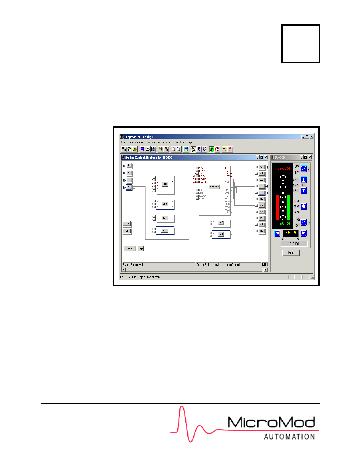
LoopMaster™ SL6000 CONFIGURATION TOOLKIT
PN26003 Rev. 1
Page 2

MicroMod Automation, Inc.
The Company
MicroMod Automation is dedicated to improving customer efficiency by providing the most ost-effective, application-specific process
solutions available. We are a highly responsive, application-focused company with years of expertise in control systems design and
implementation.
We are committed to teamwork, high quality manufacturing, advanced technology and unrivaled service and support.
The quality, accuracy and performance of the Company's products result from over 100 years experience, combined with a continuous
program of innovative design and development to incorporate the latest technology.
Use of Instructions
∆ Warning. An instruction that draws
attention to the risk of injury or death.
❢ Caution. an instruction that draws
attention to the risk of the product,
process, or surroundings.
Although Warning hazards are related to personal injury, and Caution hazards are associated with equipment or property damage, it
must be understood that operation of damaged equipment could, under certain operational conditions, result in degraded process
system performance leading to personal injury or death. Therefore, comply fully with all Warning and Caution notices.
Information in this manual is intended only to assist our customers in the efficient operation of our equipment. Use of this manual for
any other purpose is specifically prohibited and its contents are not to be reproduced in full or part without prior approval of MicroMod
Automation, Inc.
✎Note. Clarification of an instruction
or additional information.
i Information. Further reference for
more detailed information or
technical details.
Licensing, Trademarks and Copyrights
Easy-Tune, LoopMaster, and Micro-Mite are trademarks of MicroMod Automation, Inc. Micro-DCI is a registered trademark of
MicroMod Automation, Inc.
All other trademarks are the property of their respective owners.
Copyright 2005 MicroMod Automation Inc. [October 2005]
Health and Safety
To ensure that our products are safe and without risk to health, the following points must be noted.
The relevant sections of these instructions must be read carefully before proceeding.
1. Warning Labels on containers and packages must be observed.
2. Installation, operation, maintenance and servicing must only be carried out by suitably trained personnel and in
accordance with the information given or injury or death could result.
3. Normal safety procedures must be taken to avoid the possibility of an accident occurring when operating in conditions
of high pressure and/or temperature.
4. Chemicals must be stored away from heat, protected from temperature extremes and powders kept dry. Normal safe
handling procedures must be used.
5. When disposing of chemicals, ensure that no two chemicals are mixed.
Safety advice concerning the use of the equipment described in this manual may be obtained from the Company address on the back
cover, together with servicing and spares information.
All software, including design, appearance, algorithms and
source codes, is copyrighted by MicroMod Automation, Inc.,
and is owned by MicroMod Automation or its suppliers.
Page 3

53HC2600 INSTRUCTION MANUAL
TABLE OF CONTENTS
READ FIRST ...............................................................................vii
1.0 - INTRODUCTION ...................................................................1
1.1 LoopMaster™................................................................................................1
1.2 What You Will Need.......................................................................................1
1.3 About This Manual.........................................................................................2
1.4 Text Conventions Used In This Manual.........................................................2
1.5 SL6000 Configuration Toolkit Model Numbers ..............................................3
2.0 - INSTALLATION.....................................................................5
2.1 Installing LoopMaster ....................................................................................5
2.1.1 To Install LoopMaster for Windows 3.1 or Windows 95/98...............5
2.1.2 What Gets Installed..........................................................................6
2.1.3 To Install LoopMaster for Windows 2000 Professional/Windows XP
Professonal................................................................................7
2.1.4 Hardware Installation.......................................................................8
2.1.4.1 Installing the Hardware Key...........................................8
2.1.5 LoopMaster Software Installation.....................................................9
2.2 Uninstalling LoopMaster Under Windows 3.1 or
Windows 95.......................................................................................13
2.3 Uninstalling LoopMaster Under Windows 2000 Professional or Windows XP
Professional.............................................................................................14
2.3.1 Removing the LoopMaster Software..............................................14
2.3.1.1 Method 1......................................................................14
2.3.1.2 Method 2......................................................................15
3.0 - GUIDED TOUR....................................................................17
3.1 Starting LoopMaster....................................................................................17
3.1.1 To start LoopMaster........................................................................17
3.2 Online Or Offline?........................................................................................17
3.3 Offline Configuration....................................................................................18
3.4 Tagname......................................................................................................18
3.5 The Strategy Assistant.................................................................................18
3.6 Main LoopMaster Window...........................................................................19
3.7 Control Strategy Window.............................................................................19
3.8 Typical Offline Parameter Value Change.....................................................20
3.8.1 Changing the AI Input Base ...........................................................20
3.8.2 Changing the AI Digital Filtering.....................................................20
3.8.3 Adding DOCUMENTER Information ..............................................21
3.9 Viewing the DOCUMENTER Report............................................................22
3.10 Saving the Configuration ...........................................................................24
3.11 Changing Function Block Connections......................................................24
Contents i
Page 4

53HC2600 INSTRUCTION MANUAL
3.12 Configuring the FNC Block........................................................................26
3.13 Using the Interactive Training Screens......................................................27
4.0 - ONLINE CONFIGURATIONS..............................................31
4.1 LoopMaster Online..................................... ... .... ... ... ... .................................31
4.2 Connecting A Micro-Mite Controller To Your PC..........................................31
4.3 Multi-Drop Network Connections.................................................................31
4.4 Starting An Online Configuration.................................................................36
4.4.1 Online or Offline? ...........................................................................36
4.4.2 Select a Controller..........................................................................36
4.4.3 Main LoopMaster Window with Front Panel Window.....................37
4.4.4 Typical Online Parameter Value Change .......................................38
4.4.4.1 Changing the AI Input Base Online..............................39
4.4.4.2 Changing the AI Digital Filtering Online.......................39
4.4.4.3 Documenter Supplementary Information ................. ....39
4.4.5 Changing Function Block Connections Online...............................39
4.4.6 Configuring the FNC Block Online .................................................41
4.4.6.1 Using the Interactive Training Screens Online.............42
4.5 Uploading a Controller Configuration To a File............................................43
4.6 Downloading a File to a Controller ..............................................................44
5.0 - USING THE DOCUMENTER .............................................. 47
5.1 Documenter Report.................................... ... .... ... ... ... .... ... ... ... ... .................47
5.1.1 Documenter Fonts..........................................................................47
5.1.2 Header and Footer.........................................................................47
5.1.3 Margins...........................................................................................47
5.1.4 Title Page.......................................................................................47
5.1.4.1 Documenter Title......... ... .... ... ... ... .... ... ... ... ... .... ... ... ... ....48
5.1.4.2 Documenter Function Block Overview.........................48
5.1.5 Parameter Listing Pages................................................................48
5.1.5.1 Parameter Listing Format ............................................48
5.1.6 Rear Connection Diagrams............................................................48
6.0 - ADVANCED TOPICS .......................................................... 49
6.1 How to Start An Online Configuration Directly.............................................49
6.2 How To Start An Offline Configuration Directly............................................49
6.3 LoopMaster File Format .......... ... ... ... .... ... ... ... .... ... ... ... .... ... ... ... ... .... ... ... ... ....50
6.3.1 [Info] Section ..................................................................................50
6.3.2 [Documenter] Section.....................................................................50
6.3.3 [Database] Section.........................................................................52
6.4 Downloading A File......................................................................................52
6.4.1 Download Selectivity......................................................................52
6.5 Strategy Assistant Start Base File ...............................................................52
ii Contents
Page 5

53HC2600 INSTRUCTION MANUAL
7.0 - TROUBLESHOOTING ........................................................55
7.1 SERIAL.386 File Installation Instructions ....................................................55
7.2 Documenter Problems.................................................................................56
7.3 Display Problems.........................................................................................56
7.3.1 THREED.VBX Display Problems ...................................................57
7.4 COM Port Selection................. ... ... ... .... ... ... ... .... ... ... ... .................................57
8.0 - MICRO-MITE CONTROLLER OPTIONS............................59
8.1 Connecting the Option Modules.................................... .... ... ... ... .... ... ... ... ... .59
8.2 Communications Module.............................................................................59
8.3 2DI/2DO Option Module ..............................................................................59
8.4 Universal Ananlog Input Module..................................................................60
Appendix A - GLOSSARY OF TERMS ......................................61
Appendix B - DATABASE CROSS REFERENCE ..................... 63
Appendix C - MENUS AND TOOLBAR BUTTONS ................... 75
LIST OF FIGURES
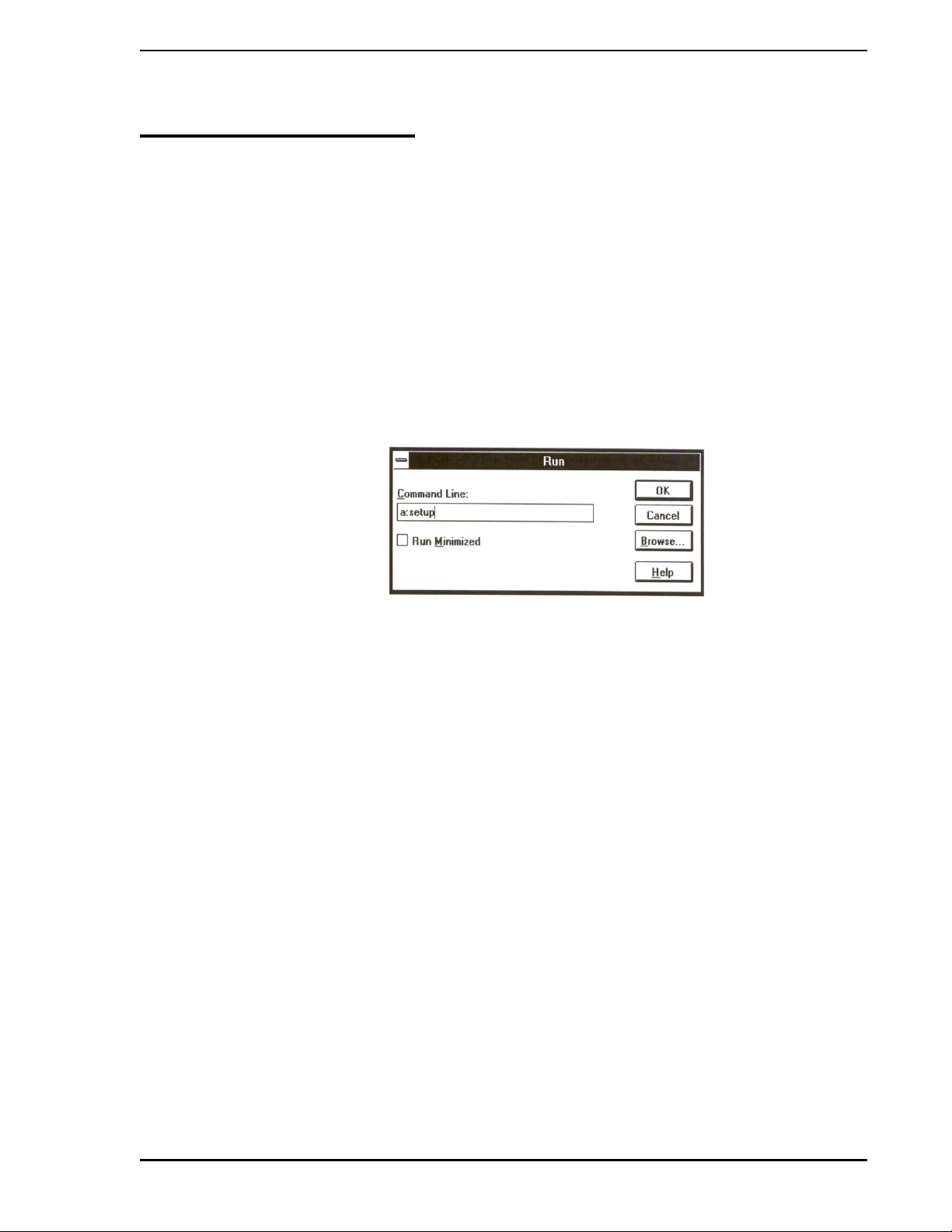
Figure 2-1. Run Dialog Box .................................... ... ... ......................................5
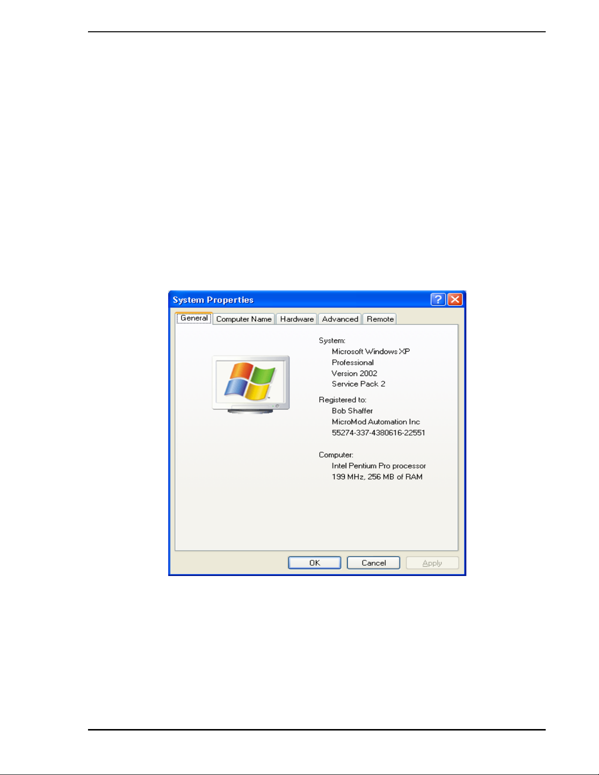
Figure 2-2. System Properties Window, General Tab Displayed ........................7
Figure 2-3. Hardware Key for Use with LoopMaster System Software ..............8
Figure 2-4. Menus for Uninstalling LoopMaster Software, Method 1 ................14
Figure 2-5. Uninstalling LoopMaster Software, Method 2 .................................15
Figure 3-1. The Online or Offline? Dialog Box ........................... ... ... .... ... ... ... ... .17
Figure 3-2. Creating a New Offline Configuration ...................................... .......18
Figure 3-3. Main LoopMaster Window - Example ............................................19
Figure 3-4. Standard AI Dialog Box ........................ ... ... ... ... .... ... ... ... .... ... ... ... ... .20
Figure 3-5. Adding Information for the Documenter Report .............................21
Figure 3-6. Documenter Report, Sample First Page ........................................22
Figure 3-7. Documenter Report, Last Page, Rear Connections Example ........23
Figure 3-8. Selecting the C Scheme A Input Button .........................................25
Figure 3-9. Connection Drawing Example, FNC Output X Source ...................25
Figure 3-10. Connection Drawing Example, AI1 Source ..................................26
Figure 3-11. Equation Constant Configuration Example ...................................27
Figure 3-12. Sample Control Scheme Window ................................................28
Figure 3-13. SAMPLE.cn1.Output1 Dialog Window ......................................... 28
Figure 4-1. RS-232 Single Controller Cabling .................................................. 32
Figure 4-2. Datalink Cabling ................................................................ ... ... ... ... .33
Figure 4-3. RS-232/485 Cable ...................... ... ... .... ... ... ... ... .... ... ... ... .... ... ... ... ... .34
Figure 4-4. ITB Track Clearances .................................................... .......... .......35
Contents iii
Page 6

53HC2600 INSTRUCTION MANUAL
Figure 4-5. Online or Offline? Dialog Box ............................................ ............. 36
Figure 4-6. Select a Controller Dialog Box ....................................................... 37
Figure 4-7. Control Strategy Window and Front Panel Window .......................37
Figure 4-8. Online Standard AI Dialog Box .......................................................38
Figure 4-9. FNC Function Block, A Input Selected .... .......................................40
Figure 4-10. FNC Function Block, Connection Example ..................................41
Figure 4-11 . Function Block Equations Dialog Window ....................................41
Figure 4-12. Control Scheme Dialog Window ..................................................42
Figure 4-13. SL6000.cn1.Output1 Dialog Window ...........................................42
Figure 4-14. Upload Dialog Window .................................................................44
Figure 4-15. Upload From Controller Window ........................ .......................... 44
Figure 4-16. Download to Controller Window ............................ .......................45
Figure 6-1. LoopMaster Properties Dialog Box .. .... ... ... ... .... ... ...... ... .... ... ... ... ....49
Figure 8-1. Micro-Mite Controller Connectors ..................................................59
Figure B-1. Accessing the SL6 Database Dialog Box ......................................63
Figure B-2. Manual Write to SL6 Database Dialog Box ....................................63
Figure C-1. LoopMaster Menu and Button Overview .......................................75
List of Tables
Table 2-1. Files installed In LoopMaster Directory.............................................. 6
Table 6-1. Info Section Variables...................................................................... 50
Table 6-2. Documenter Section Variables ........................................................ 50
Table B-1. Prompt-to-Datapoint Number Cross Reference List........................ 64
iv Contents
Page 7

READ FIRST
∆ WARNING: INSTRUCTION MANUALS
53SU6000 INSTALLATION AND SETUP GUIDE
Do not install, maintain, or operate this equipment
without reading, understanding and following the proper
MicroMod Automation Inc. instructions and manuals,
otherwise injury or damage may result.
Read these instructions before starting installation;
save these instructions for future reference.
RETURN OF EQUIPMENT
All Flowmeters and/or Signal Converters being returned
to the factory for repair must be free of any hazardous
materials (acids, alkalis, solvents, etc.). A Material Safety
Data Sheet (MSDS) for all process liquids must
accompany returned equipment. Contact the factory for
authorization prior to returning equipment.
Contacting MicroMod Automation Inc.
Should assistance be required with any MicroMod Automation Inc. product, use the follo wing contact
information.
Telephone:
MicroMod Automation Inc., Rochester NY:
Phone: 1 (585) 321-9200
Fax: 1 (585) 321-9291
MicroMod Automation Inc., Southampton, PA:
Phone: 1 (215) 355-4377
Fax: 1 (215) 355-4378
E-Mail:
support@micmod.com
Read First vii
Page 8

53SU6000 INSTALLATION AND SETUP GUIDE
viii Read First
Page 9

53HC2600 INSTRUCTION MANUAL
1.0 INTRODUCTION
1.1 LoopMaster™
Thank you for purchasing the 53HC2600 LoopMaster™ SL6000 Configuration Toolkit!
LoopMaster is the graphical configuration package for the 53SL6000 Micro-Mite controller. LoopMaster
produces Micro-Mite controller configurations, saves them to files, sends them to a Micro-Mite controller,
and documents the configuration in a comprehensive report.
LoopMaster contains time-saving features like the Strategy Assistant to help you get started, interactive
training screens to explain parameters and guide you through configuration dialogs (see dialog in Appendix A, Glossary of Terms), and an integrated Documenter to automatically generate a complete configuration report. On-the-spot assistance is available; click the Help button to view the help screen related to
your current situation.
1.2 What You Will Need
To use LoopMaster with Windows® 3.1 or Windows® 95, you will need:
•Microsoft
• Pointing device (mouse, trackball, etc.).
• 4 megabytes of RAM.
®
Windows 3.1 or Windows 95.
• 3 megabytes of free disk space.
• VGA 640 x 480 display (16-color preferred) or higher.
• One COM port available.
• 3.5” disk drive for the LoopMaster installation diskette.
To use LoopMaster with Windows 2000 Professional or Windows XP Professional, you will need:
• A personal computer (PC) that meets the minimum require ments for running the chosen
Windows operating system.
• The Windows 2000 Professional or Windows XP Professional SP2 software.
• A CD-ROM drive for the LoopMaster installation CD-ROM.
• Pointing device (mouse, trackball, etc.).
• VGA 640 x 480 display (256-color preferred) or higher.
• A 3.5 inch floppy disk drive for small capacity removable storage.
• A parallel port for printing and hardware key inst allation.
• A full size ISA bus slot is required for each installed Supervisor card.
Introduction 1
Page 10

53HC2600 INSTRUCTION MANUAL
1.3 About This Manual
This manual provides information to install and use the LoopMaster SL6000 Configuration Toolkit.
It is assumed that you are familiar with Microsoft Windows™ and have a basic knowledge of process con-
trol terminology. If you are not familiar with Windows, try running the Windows Tutorial, which can be
accessed using the menues available from the Start button; for example, on a Windows XP Professional
system, select the sequence Start > All Programs > Accessories > Tour Windows XP to initiate the
tutorial.
Section 1.
Introduction
Section 2.
Installation
Section 3,
Guided Tour
Section 4.
Online Configurations
Section 5.
Using The Documenter
Section 6.
Advanced Topics
Section 7.
Troubleshooting
Section 8.
Micro-Mite Controller Options
Appendix A.
Glossary of Terms
Provides a LoopMaster overview and minimum system
requirements.
Provides step-by-step in structions to inst all LoopMaster onto
your system.
How to start LoopMaster and create a simple offline
configuration.
How to connect a Micro-Mite controller to your personal
computer and Micro-Mite controller Datalink cabling. Also,
how to develop an online configuration and download a
configuration file to a Micro-Mite controller.
Customizing the Documenter Report and what the
Documenter does.
Command line options, LoopMaster file format, specific
information about downloading files.
A list of potential problems and their remedies.
Information on supporting Micro-Mite controller option
modules in LoopMaster.
Contains a brief description of unique LoopMaster terms.
Appendix B.
Database Cross Reference
Appendix C.
Menus and Toolbar Buttons
Provides a prompt-to-datapoint location number cross
reference list.
Provides a quick reference that describes the purpose of
each menu command and toolbar button.
1.4 Text Conventions Used In This Manual
File > Print indicates access File on the Main Menu bar and select Print from the pull-down menu.
2 Introduction
Page 11
53HC2600 INSTRUCTION MANUAL
1.5 SL6000 Configuration Toolkit Model Numbers
Refer to the product data sheet or data tag for the model number of the product furnished. The details of a
specific number are as follows:
53 HC26 0 A _ 0
Controllers
Design Designator
System Type
Windows 3.1 or Windows 95 Standalone 0
Windows 2000 Pro/XP Pro Standalone 1
Add-on to existing hardware security device 2
Reserved 0
Design Level A
Interface
None 0
RS-232 (Cable only: 9 Pin D to SL6000 RS-232 Module) 1
RS-232 (Cable and Communications Module) 2
RS-485 (Cable and RS-232 to RS-485 converter) 3
Media Type
None 0
3.5 inch, 1.44 MB diskette 1
CD-ROM 2
Introduction 3
Page 12

53HC2600 INSTRUCTION MANUAL
4 Introduction
Page 13
53HC2600 INSTRUCTION MANUAL
2.0 INSTALLATION
2.1 Installing LoopMaster
The LoopMaster setup utility installs the program, help file, and the necessary support files onto your hard
drive.
2.1.1 To Install LoopMaster for Windows 3.1 or Windows 95/98
1. Insert the LoopMaster diskette into the flop p y driv e.
2. From Program Manager, click on the File menu and select Run.
3. In the Run dialog (Figure 2-1), type a:setup and click OK. Type b:setup if installing from
the b: drive. The LoopMaster splash screen will appear while Setup initializes.
Figure 2-1. Run Dialog Box
4. Setup asks if you want to install LoopMaster onto your hard drive. Click Yes.
5. Depending on your hardware, Setup may make some suggestions. Click OK after reading
any suggestions.
6. Setup asks for the destination drive and directory. Type in the drive and subdirectory where
you want Setup to install all LoopMaster files. If the subdirectory does not exist, Setup will
create it for you. LoopMaster uses a straightforward subdirectory tree where all files are
installed into the same subdirectory.
7. If a warning message appears indicating your system has an old version of SERIAL.386
installed in the Windows System subdirectory, click OK. If the warning message does not
appear , it indicates your SERIAL.386 file is at an acceptable version or it is not used by your
system; proceed to step 9.
✎ NOTE Ignore step 3 of the Microsoft instructions, where it states the
WG1001 disk should be inserted into the floppy drive.
8. Microsoft’s instructions to install the SERIAL.386 file appear on the monitor . A copy of these
instructions is provided in Section 7.0, TROUBLESHOOTING. Do not remove the LoopMaster
diskette from its drive. Follow the Microsoft instructions provided in Section 7.0 to install the
SERIAL.386 file.
Installation 5
Page 14

53HC2600 INSTRUCTION MANUAL
9. After all the files are installed, Setup adds five icons to the LoopMaster program group. Setup
also creates the group if it does not exist.
• LoopMaster icon
• LoopMaster Help icon
• Readme icon
• Uninstall icon
• Documents icon
10. Before starting LoopMaster, double-click on the Readme icon to view up-to-date information
on this version.
This completes the LoopMaster installation. Section 3.0 provides a brief guided to ur of LoopMaster.
2.1.2 What Gets Installed
All of the LoopMaster files are installed into the same subdirectory. Here are the files installed onto your
drive.
Table 2-1. Files installed In LoopMaster Directory
File Description
LOOPMSTR.EXE LoopMaster Program file
LOOPMSTR.HLP LoopMaster Help file
WSUP31.DLL MicroMod Automation Inc. Communications Dynamic
Link Library (.DLL)
WSUP.INI .INIfile required by WSUP31.DLL
LMTRAIN.TXT LoopMaster training screens text file
UIM.TXT Universal Input Module text file
README.TXT Additional information text file
SPIN.VBX Spin button .VBX control
ANIBRT.VBX Pushbutton .VBX control
THREED.VBX Assorted .VBX controls
SS3D2.VBX 3D drop-down list box .VBX control
START.S6D Strategy Assistant start base file
GAUGE.VBX Gauge .VBX control
In addition to these files, the LOOPMSTR.INI file is created when you run LoopMaster for the first time.
This file will be located in your Windows directory.
6 Installation
Page 15
53HC2600 INSTRUCTION MANUAL
2.1.3 To Install LoopMaster for Windows 2000 Professional/Windows XP Professonal
1. Set up the Base PC by connecting all peripheral hardware units to the base PC, including the
monitor, keyboard, mouse, and CD-ROM unit (if it is an external CD-ROM unit). Connect the
base PC and all peripheral units to a power sour ce. See the instructions that are included with
the PC for setting up these components.
2. Verify or install the Windows operating system software. For installations performed after
October 2005, LoopMaster requires that the base PC is running Windows 2000 Professional
or Windows XP Profession SP2.
NOTE: Existing installations on a base PC running Windows NT 4.0 will continue to work.
Locate the button labeled START at the bottom left of the base PC monitor scr een and click it.
Right-click on the My Computer menu item, then click on the View System Information
option. The version information for the system will be displayed on the General tab of the
resulting pop-up window (see Figure 2-2).
Figure 2-2. System Properties Window, General Tab Displayed
Verify that either Windows 2000 Pro fessional or Windows XP Professional SP2 is inst alled. If
the information on this window indicates that the op erating system is Windows 95 or Windows
NT Server, then you must install Windows 2000 Professional or Windows XP Professional at
this time. If you need to install Windows 2000 Professional or Windows XP Professional,
follow the instructions included with the ap pr op r iate op er at ing syste m .
Installation 7
Page 16
53HC2600 INSTRUCTION MANUAL
2.1.4 Hardware Installation
2.1.4.1 Installing the Hardware Key
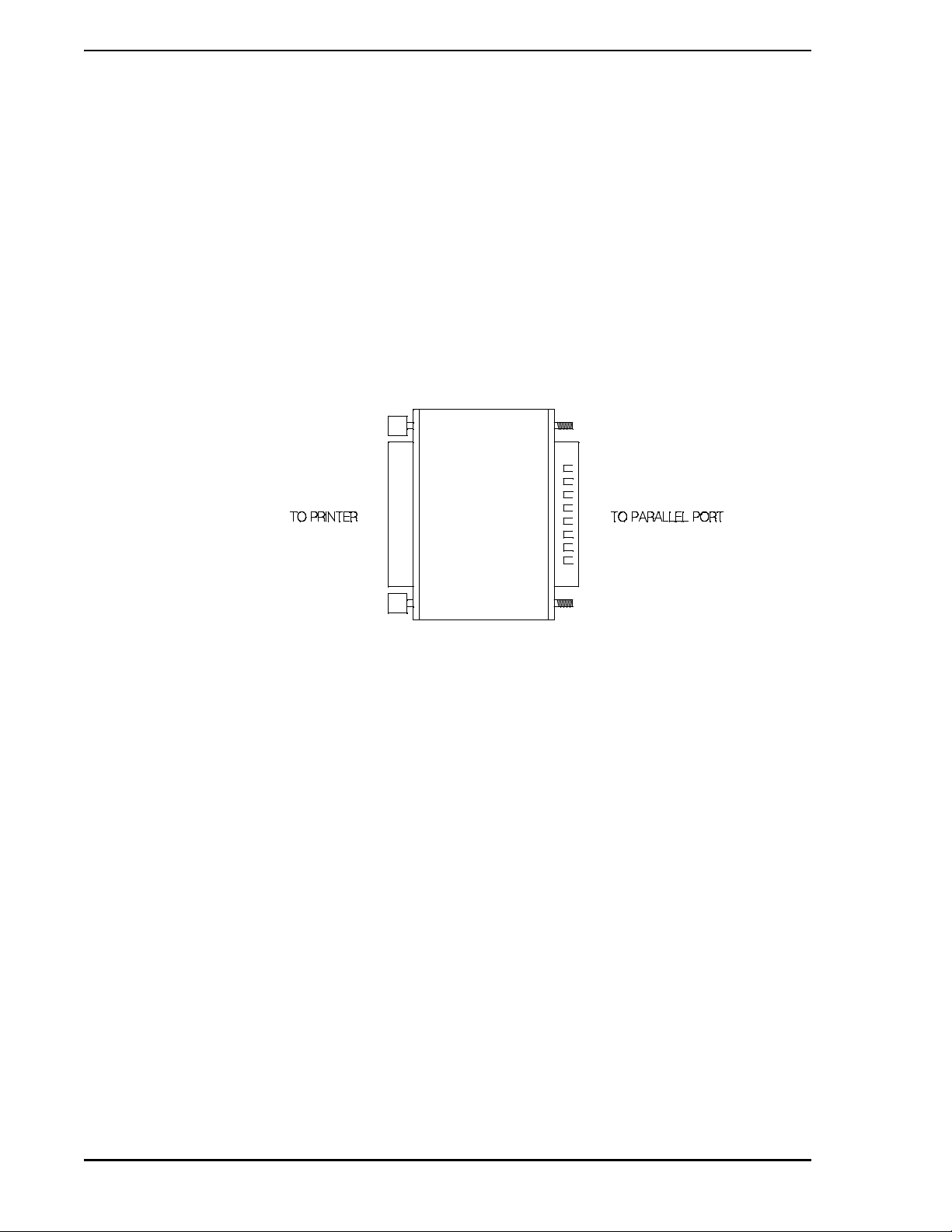
A “Hardware Key” is supplied when the standalone version is specified in the model number.
The LoopMaster software is licensed by MicroMod Automation Inc. The license is protected b y a hardware
key, shown in Figure 2-3, which must be attached to the PC’s parallel port. The hardware key does not
functionally compromise the parallel port. When installed, the hardware key provides a female connecto r
allowing a parallel device to be attached to it. If a device (for examp le, a printer) is already connected to th e
parallel port, remove the parallel cable co nnector, connect the hardware key to the port, and reconnect the
cable to the hardware key. Signals to and from the attached parallel device will be passed through the
hardware key. The hardware key must be installed for the LoopMaster software to run.
Figure 2-3. Hardware Key for Use with LoopMaster System Software
Installation of LoopMaster software and licenses can proceed if the hardware key is not att ached; however ,
no LoopMaster windows can be opened. Instead, a pop-up window will be displayed which states:
Can’t read hardware key.
Key must be attached to parallel port.
If the wrong hardware key is attached to the parallel port, a pop-up window will display the following message:
No valid LoopMaster software license found.
If problems reading the hardware key persist, test the operation of the parallel port. This can be done by
attaching a printer to the port and attempting to print to it.
8 Installation
Page 17

53HC2600 INSTRUCTION MANUAL
2.1.5 LoopMaster Software Installation
Now the process of installing the LoopMaster software can begin .
1. Pre-Setup Procedure
• Check that the LoopMaster hardware key is connected to the parallel port of the com-
puter.
• Have the LoopMaster license key ready.
• Turn on power to the base PC and boot the Windows operating system software.
• Log on to the Windows operating system software with administrative privileges. Y ou must
have administrative privileges or the installation process will not complete successfully.
• Close any open Windows applications (for example, Microsoft Word, Excel, Mail, Sched-
uler , etc.).
2. Beginning Micro-DCI Master Setup
• Insert the Micro-DCI CD into the CD-ROM drive.
• Open Explorer and select the drive letter of the CD-ROM drive.
• In the root directory of the CD-ROM, double click on the setup.exe file.
• In the Micro-DCI Master Setup, click on the LoopMaster Setup button.
3. Beginning LoopMaster Installation
• The InstallShield Wizard is loaded and then the LoopM aster System Setup window
appears.
• Click Next to begin installing the LoopMaster.
• Click the OK button if a font-size information window opens.
✎ NOTE If the Micro-DCI Communications Services are being installed for
the first time, the setup routine will prompt for them to be installed.
Click on the OK button and prompts will appear for Items 4 through
9. Otherwise these items will be skipped and the installation
process will proceed to item 10.
4. The Micro-DCI Communication Services
• The Micro-DCI Communication Services Setup window appears. Click on the Next button
to proceed.
5. Micro-DCI Communication Services Location
•The Choose Destination Location window appe ars, which enables you to sp ecify the drive
and directory where you want the Micro-DCI Communication Services installed. You can
accept the default path of C:\udci by clicking the Next button, or you can change the
destination directory by clicking the Browse button.
• If you clicked the Browse button, enter both the drive and directory you want to use as the
destination directory in the Choose Directory field.
• Click the Next button.
• If the directory does not exist, Setup will ask you if it should be created. If this window
appears, click the Yes button.
Installation 9
Page 18

53HC2600 INSTRUCTION MANUAL
•The Select Program Folder window appears. Select the program Folder you want the pro-
gram icons added to. The Micro-DCI Comm Services folder is selected by default as the
folder for the program icons. You can accept the default, select an existing program fold er,
or type a new program folder.
• Click the Next button.
•A Setup window with a progress bar appears and the Micro-DCI files begin to install.
•The Enter Information window appears and prompts you to enter a maximum of eight-
characters as a name for your entire Micro-DCI local system.
• Either accept the default name or enter a name and click the Next button.
✎ NOTE If this PC is a node on a Micro-PWC network, the selected name
will be used to identify the Micro-DCI communication interface on
this PC; therefore this name must be unique from all ot he r no de
names on the Micro-PWC global network.
The progress bar then finishes updating and the Setup process continues.
6. Installing Data Access Objects (DAO)
• The LoopMaster uses Data Access Objects (DAO’s) to store local databases. If Microsoft
DAO 3.5 has not been previously installed, LoopMaster launch es the Dat aAccess Objects
(DAO) SDK Setup window. This program is only installed the fir st time then LoopMa ster is
installed on your PC.
• Click the Next button and DAO Setup will copy about 25% of the files, then close and
return to the Main LoopMaster Setup program. It is correct that on ly about 25% of th e files
are copied. These are the only files required.
• If DAO 3.5 is already present on the system, Item 5 will be bypassed and the setup program will perform Item 6.
7. Installing Micro-DCI Services and Program Folder
• The Micro-DCI Services will be automatically installed. A window will pop up to install
these services.
• When the services are installed, the window will close and return you to the Main LoopMaster Setup.
• The Micro-DCI Communications Services Setup program then creates the Micro-DCI
Communications Services program folder and automatically adds the appropriate icons
for the Micro-DCI Communications Services product.
8. Installing Micro-DCI Communications Services License Key
Setup will launch the Micro-DCI License Administration program to enter your license keys.
License keys must be added one at a time.
•Select Add new license... from the License menu.
• In the License Administration dialog, type in your license information for one license key.
Be certain to enter all information exactly as it appears. Click Save and this information
will be verified and written to the license file. If the information entered is not correct, a
pop-up message box will appear and the information will have to be corrected.
10 Installation
Page 19

53HC2600 INSTRUCTION MANUAL
The following license keys may be provided:
udci - licenses MIcro-DCI Communication Services for 300 tags
udciunlim - licenses MIcro-DCI Communication Services for unlimited tags
loopmaster - licenses the LoopMaster product features
✎ NOTE Entry of the License Keys is not case-sensitive.
•Select Exit from the File menu when finished.
9. Adding Micro-DCI Networks
If you would like to add Micro-DCI instrument networks, click on the Yes button when given the
choice. The Add Micro-DCI Networks window appears. Click the Next button.
• The Setup program then start s the Super32 p rogram, which is a L oopMaster program that
enables you to add Micro-DCI network instruments to your system. This is a good time to
add Micro-DCI networks to your system since you need to reboot your PC after installing
the LoopMaster software and after you install the Micro-DCI networks.
• The first Network Wizard window lets you select whether you are adding a network that is
connected to your system through a supervisor board (SUP) or though a COM port
(COM). Select either SUP or COM, then click the Next button.
• In the Network Wizard - Network Attributes window, enter a Network Name (up to 9 char-
acters) and select a Network Position, then click the Next button.
•The Network Wizard - Backup window appears. Select Master or Backup, and then click
the Next button.
•The Network Wizard - Network Parameters window appears. If SUP was selected in the
first Network Wizard window, set the I/O Port Addres s to agree with the address jumpers
on the Supervisor Board. The parameters change depending on the type of network that
is being installed.
• After selecting the I/O Port Address (if required), click the Next button.
• In the Network Wizard - Finish window, click the Finish button.
• A window appears confirming that the Network was added successfully. Click the
OK button to proceed.
• If the network was added successfully, Super32 will ask if another network is to be added.
If so, repeat the above steps until all desired Micro-DCI networks have been added.
Answering No exits Super 32 and opens the Read-Me file in a Notepad window.
• When the Read-Me file window is closed, a window appears asking if the the computer
should be rebooted for the system to recognize the newly added SUP Micro-DCI networks. Click the No button at this time.
10. LoopMaster System Target Location
•The LoopMaster Target Location window then appears, which enables you to specify the
drive and directory where you want the LoopMaster installed. You can accept the default
path of C:\LoopMaster by clicking the Next button or you can change the destination
directory by clicking the Browse button.
Installation 11
Page 20

53HC2600 INSTRUCTION MANUAL
• If you clicked the Browse button, enter both the drive and directory you want to use as the
destination directory in the Choose Directory field.
• If the directory does not exist, Setup will ask you if it should be created. If this window
appears, click the Yes button.
• Click the Next button.
•The Setup window progress bar reactivates and the Micro-DCI files begin to install.
11. Installing the LoopMaster license key
Setup will launch the Micro-DCI License Administration window to enter your license keys.
• If the loopmaster license key was entered during Item 8, it need not be entered again.
Close the window by clicking on the close button in the upper right-hand corner of the window.
✎ NOTE If the Micro-PWC software has been installed, the Micro-PWC
Maintenance Utility window will appear instead of the Micro-DCI
License Administration window
• If the LoopMaster License Key has not been entered previously, select Add new
license... from the License menu.
• In the License Administration dialog, type in your license information for one license key.
Be certain to enter all information exactly as it appears. Click Save and this information
will be verified and written to the license file. If the information entered is not correct, a
pop-up message box will appear and the information will have to be corrected.
The following license key is used:
loopmaster - licenses all product features
• When finished, select Exit from the File menu.
12. Select Program Folder
The Select Program Folder window appears. Se lect the program Folder you want the progr am
icons added to. The LoopMaster folder is selected by default as the folder for the program
icons. You can accept the default, select an existing program folder, or type a new progra m
folder.
• Click the Next button.
13. New Program Folder
• The LoopMaster Setup program then creates the LoopMaster program folder and auto-
matically adds the appropriate icons for the LoopMaster product.
14. Integrating Into Super32
• LoopMaster can be registered to be the default configuration program for SL6000 control-
lers in the Super32 Micro-DCI network management utility.
• When asked if LoopMaster should be integrated into Supe r32, select Yes to register Loop-
Master as the default configuration program or No to use the Super32’s basic SL6000
configuration program.
15. Finishing the Installation
12 Installation
Page 21

53HC2600 INSTRUCTION MANUAL
• When the Installation is Complete window appears, click on the OK button.
• At this point the Notepad application opens and a LoopMaster Read Me file appears
containing LoopMaster release information. When you have finished reading this document, close Notepad using the Close button in the upper right-hand corner of the window.
• Any windows remaining open may be closed, if desired, using the Close button in the
upper right-hand corner.
• When the Read-Me file window is closed, a window appears asking if the the computer
should be rebooted. Click the Yes button to have the system recognize the new software.
• This completes the setup process.
2.2 Uninstalling LoopMaster Under Windows 3.1 or Windows 95.
Use this procedure to remove the LoopMaster software and its associated files from your system.
1. Delete the LOOPMSTR subdirectory. This is the subdirectory where Setup installed
LOOPMSTR.EXE and all associated files. Deleting this subdirectory tree pur ges mo st of
LoopMaster from your system.
2. If LOOPMSTR was ever started, LoopMaster created an INI file in your Windows directory.
Delete LOOPMSTR.INI from your Windows directory.
3. Since it is possible to store LoopMaster database files anywhere on your system, delete any
*.S6D files not in the LOOPMSTR directory.
4. From Program Manager, select and minimize the LoopMaster group, then press the Delete
key. It is not necessary to delete each individual icon to delete the group.
Installation 13
Page 22
53HC2600 INSTRUCTION MANUAL
2.3 Uninstalling LoopMaster Under Windows 2000 Professional or Windows XP Professional
2.3.1 Removing the LoopMaster Software
There are two ways to remove the LoopMaster software and its associated files from your system.
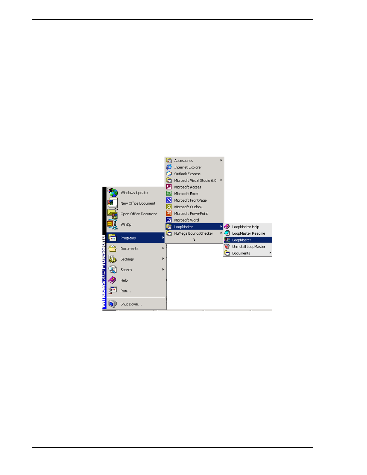
2.3.1.1 Method 1
1. Click the START button.
2. Select this sequence of menu items: PROGRAMS > LOOPMASTER > UNINSTALL
LOOPMASTER. (See menus illustrated in Figure 2-4.)
14 Installation
Figure 2-4. Menus for Uninstalling LoopMaster Software, Method 1
Page 23
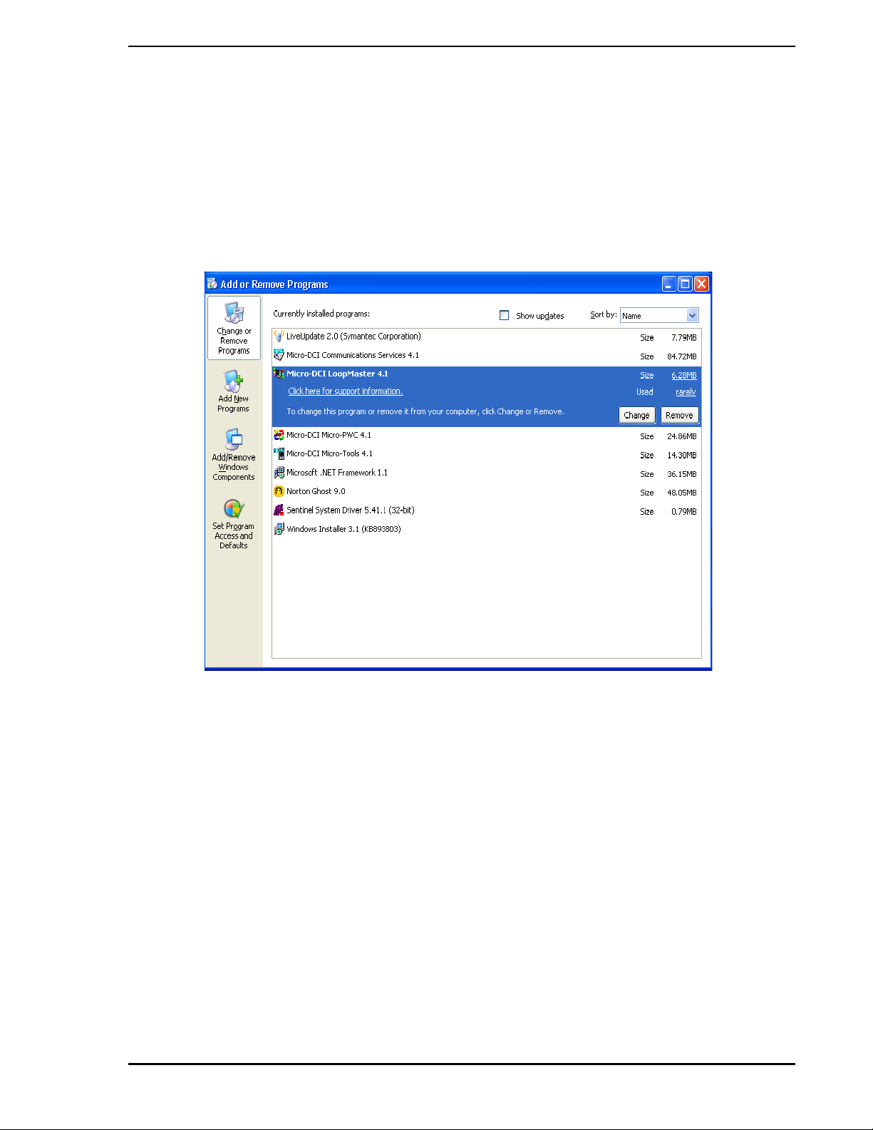
2.3.1.2 Method 2
1. Click on the START butt on.
2. Select CONTROL P ANEL.
3. Double-click on the ADD OR REMOVE PROGRAMS icon.
4. Select the item (LoopMaster) to uninstall, as illustrated in Figure 2-5.
5. Click on the CHANGE OR REMOVE PROGRAMS button to begin the uninstall proced ur e.
53HC2600 INSTRUCTION MANUAL
Figure 2-5. Uninstalling LoopMaster Software, Method 2
Installation 15
Page 24

53HC2600 INSTRUCTION MANUAL
16 Installation
Page 25
53HC2600 INSTRUCTION MANUAL
3.0 GUIDED TOUR
3.1 Starting LoopMaster
In this section, we will take a brief tour through LoopMaster and generate a simple offline configuration.
3.1.1 To start LoopMaster
1. From Program Manager, double-click on the LoopMaster icon. The main LoopMaster window
will be drawn while the application initializes.
✎ NOTE If a warning message appears indicating LoopMaster de tected a
faulty version of THREED.VBX, the startup will terminate. If this
message appears, see Section 7.3.1, THREED.VBX Display
Problems.
2. The opening dialog displays version, copyright and trademark information. Click OK.
✎ NOTE For display problems, see Section 7.3, Display Problems.
To help you get started, LoopMaster presents a few dialogs. These startup dialogs help you open the
desired configuration.
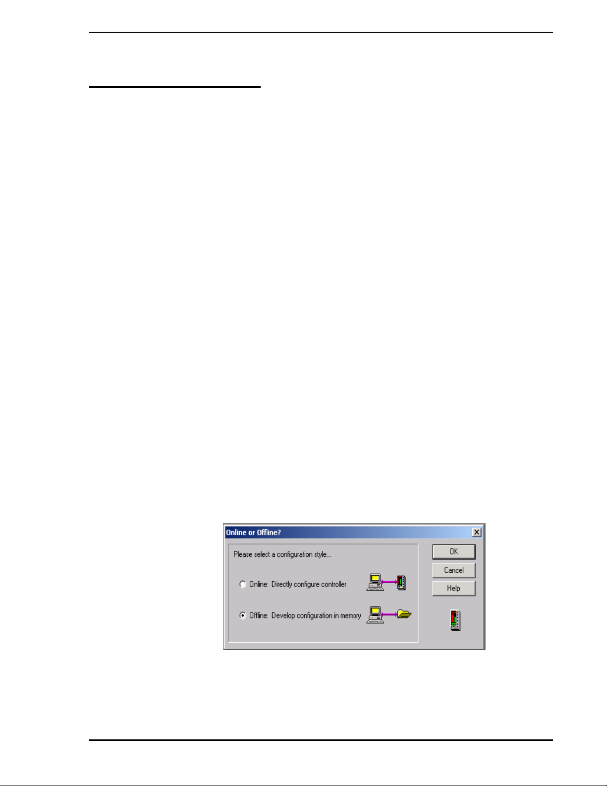
3.2 Online Or Offline?
The Micro-Mite controller is configured by setting up its configuration database. LoopMaster provides two
ways to set up a configuration database:
• Offline Configuration: Develop the configuration database in personal computer memory
and save it to a file, then download the entire database into Micro-Mite memory.
• Online Configuration: Connect a Micro-Mite controller to your personal computer and
manipulate its database through this connection.
In addition to storing the Micro-Mite controller database, offline configurations can also store transmitter
tagnames and other rear connection information. This additional information is used to produce a more
complete configuration report. Use of offline configurations is therefore recommended whenever possible.
Figure 3-1. The Online or Offline? Dialog Box
Guided Tour 17
Page 26
53HC2600 INSTRUCTION MANUAL
To create a new offline configuration:
1. In the Online or Offline? dialog, click on the Offline: Develop configurat ion in memory radio
button.
2. Click OK.
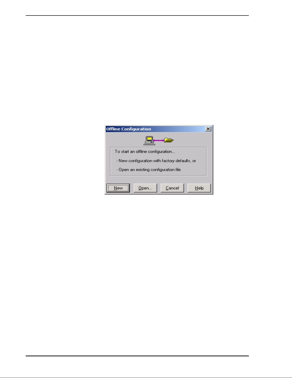
3.3 Offline Configuration
Since offline configurations can be developed without a controller, you can start with a brand new configuration of factory defaults, or edit one that was previously created. For this example, we will create a new
configuration.
Click on New to start a new offline configuation where all parameters are loaded with the factory default
settings.
Figure 3-2. Creating a New Offline Configuration
3.4 Tagname
LoopMaster uses the instrument tagname and the filename to uniquely identify a configuration. LoopMaster often shows the tagname in the title bar, so it is important to enter a descriptive tagname.
Type SAMPLE as the tagname, then click OK.
3.5 The Strategy Assistant
The Strategy Assistant contains eight commonly used control strategies. A strategy is a complete configuration from inputs to outputs. When you select one of the eight preconfigured strategies, the Strategy
Assistant automatically changes parameter s and function blo ck connections for you. You may then edit the
configuration to suit your specific process.
For this example, click on Single Station Cas cade Controller, then click OK.
18 Guided Tour
Page 27
53HC2600 INSTRUCTION MANUAL
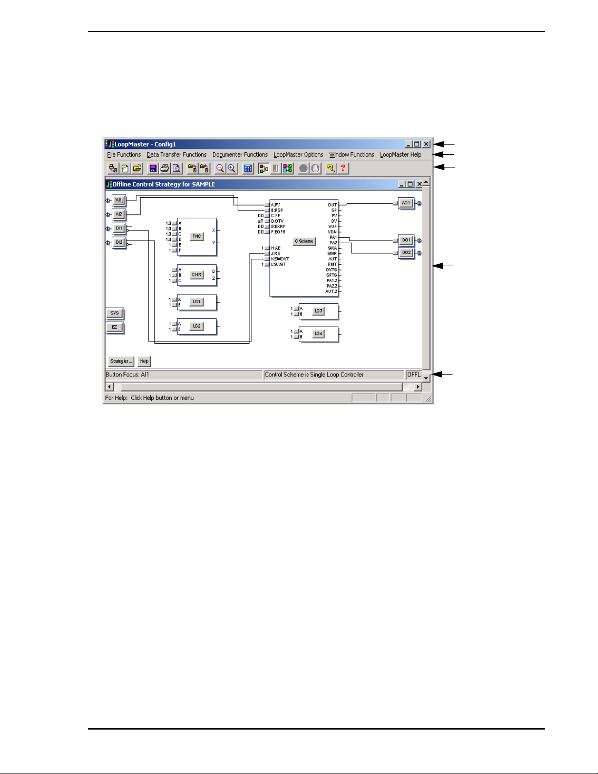
3.6 Main LoopMaster Window
The Title Bar, Main Menu and Toolbar go across the top of the main window, and the Main Status Bar runs
along the bottom. Inside is the Control Strategy Window entitled Offline Control Strategy for SAMPLE.
Tit le Bar
Main Menu
Toolbar
Control Strategy
Window
Main Status Bar
Figure 3-3. Main LoopMaster Window - Example
3.7 Control Strategy Window
The Control Strategy Window provides a function block overview, showing inputs on the left and outputs on
the right. This window has its own title bar across the top, and its own status bar along the bottom. This
status bar reminds you that the Control Scheme is Cascade Controller, and the OFFL indicates that this is
an offline configuration.
Function blocks are drawn as standard Windows pushbuttons with an extra outline and drop shadow. For
example, input blocks are AI1, DI2, etc. Output blocks are AO1, DO2, etc. Internal blocks are FNC, CHR,
C Scheme, etc. There are two stand-alone blocks: System and EZ Tune.
There are two other buttons in this window: Strategies... and Help. The Strategies... button opens the
Strategy Assistant dialog. The Help button opens the LoopMaster help screen for this window.
Move the mouse around the Control Strategy Window. When the mouse moves over a button, the Main
Status Bar displays a FlyBy message. Look to the Main Status Bar for messages.
Guided Tour 19
Page 28
53HC2600 INSTRUCTION MANUAL
3.8 Typical Offline Parameter Value Change
To configure a function block’s parameters, click on its button. We’ll start by configuring the first analog
input.
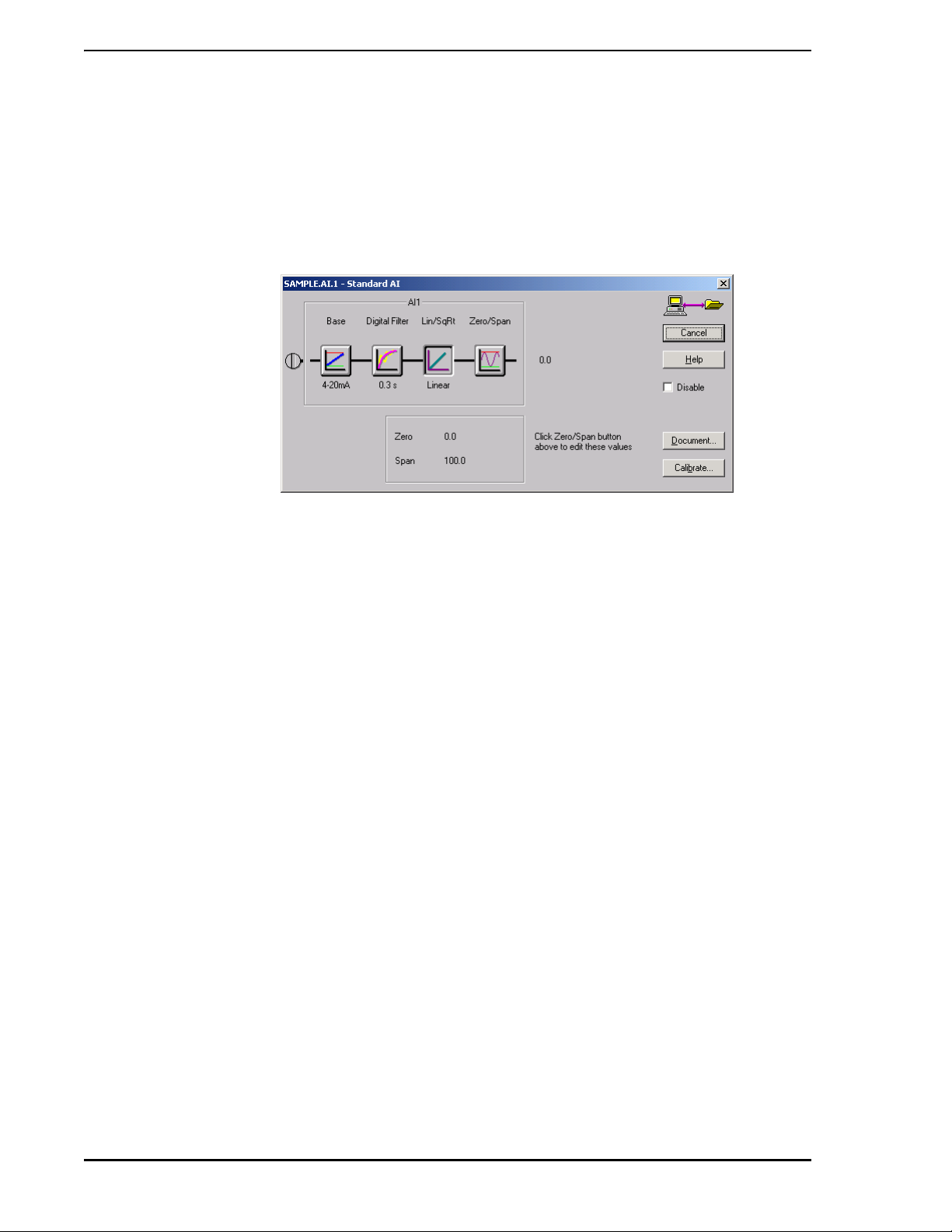
1. Click on AI1.
2. The Standard AI dialog opens, as shown in the example in Figure 3-4.
Figure 3-4. Standard AI Dialog Box
The dialog title shows the tagname, and the function block mnemonic found in the Micro-Mite controller.
This dialog is laid out to show signal flow through the analog input block, starting at the screw on the left,
flowing through the AI1 block, and producing the analog value.
When the dialog was first displayed, the button in the upper right corner was Cancel. Clicking the Cancel
button in any LoopMaster dialog leaves the configuration unchanged. Pressing the ESC key is the same
as clicking on Cancel.
3.8.1 Changing the AI Input Base
Setup the AI1 function block for a 0-20 mA input source:
1. Click on the Base button. The picture inside the button, and the text below th e button, change
between 0-20 mA and 4-20 mA configurations.
2. Change the input base to 0- 20 mA.
The AI1 Base parameter chang ed as soon as you clicked it s button . No tice the Cancel button changed to
Close because the configuration database changed while this dialog was open.
Try clicking on the Lin/SqRt button. The picture insid e and the text below the button change between
Linear and SqRoot. Set it back to Linear.
3.8.2 Changing the AI Digital Filtering
The Micro-Mite controller AI blocks are capable of smoothing input noise with a digital filter. Apply a small
amount of filtering by setting the digital filter to 1.5 seconds:
1. Click on the Digital Filter button and the Digital Filter dialog pops up.
2. Click on the down arrow to drop down the list of selections. Use the scroll bar to see other
entries in the list. Select 1.5 s.
3. Click OK to close this dialog and change the Digital Filter setting.
20 Guided Tour
Page 29
53HC2600 INSTRUCTION MANUAL
When you click OK, LoopMaster writes all the parameters in the dialog to the configuration database.
You’ll see your change in the Standard AI dialog because the text below the Digital Filter button now
reads 1.5 s. Leave the Standard AI dialog open for one more step.
3.8.3 Adding DOCUMENTER Information
Since this is an offline configuration, we can take advantage of storing additio nal information for the
Documenter Report.
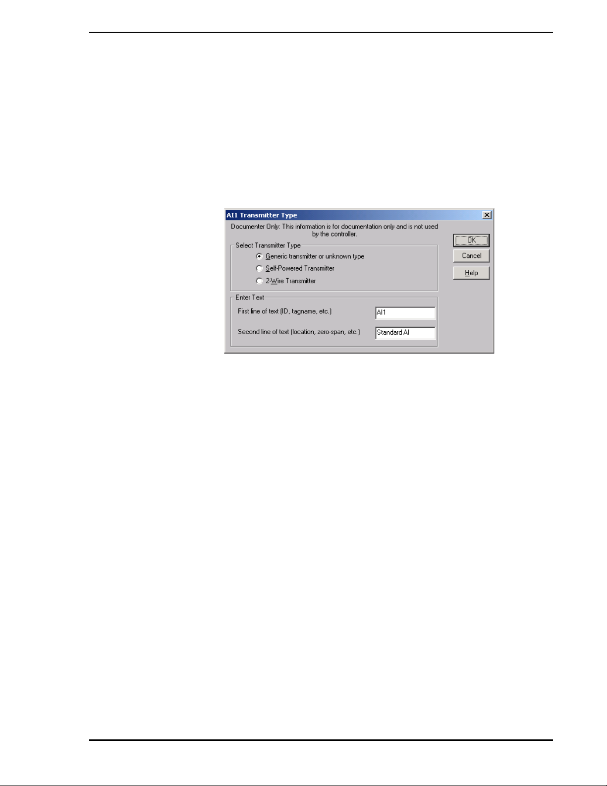
1. Click on the Doc Info... button to enter information for the Documenter Report.
Figure 3-5. Adding Information for the Documenter Report
You can select the type of transmitter connected to this AI. The wiring changes, depending upon the transmitter type. (Leave the Generic radio button on.)
The Documenter Report has a Rear Connections Diagram showing how the I/O connectors are wired. The
First line and Second line of text will be used to label this input connection. Type in the text as shown and
click OK. This information is used by the LoopMaster Documenter to enhance the rear connections diagrams.
In the Standard AI dialog, click Close to close this dialog.
This completes the configuration of the first analog input. In the next section, we’ll view the Documenter
Report and see where the Doc Info text appears.
Guided Tour 21
Page 30

53HC2600 INSTRUCTION MANUAL
3.9 Viewing the DOCUMENTER Report
Since the Documenter Report is automatically generated using the File > Print command, we can u se the
Windows print previewing capability to view the Documenter Report.
1. Select Print Preview... from the File menu, or click on the print preview toolbar button.
Print Preview toolbar button.
The first page of the Documenter is displayed with title and function block overview.
22 Guided Tour
Figure 3-6. Documenter Report, Sample First Page
Page 31

53HC2600 INSTRUCTION MANUAL
2. Click on Next Page to advance to the next page in the Documenter Report. This is a
parameter listing page.
Following the title page is a complete list of parameters involved in this configuration.
Parameters are grouped in the same order as they appear in the controller.
3. Continue to click on Next Page until the button grays out when you reach the last page.
The last page of this Documenter Report is a rear connections diagram. The top half shows
the back of the controller, and the bottom half details connections to the Standard I/O
Connector.
Figure 3-7. Documenter Report, Last Page, Rear Connections Example
4. Click on Zoom In and use the scroll bar to get a closer look at Standard I/O Connector
diagram on the bottom. This diagram details the wiring to the I/O conn ector and shows the
Guided Tour 23
Page 32

53HC2600 INSTRUCTION MANUAL
information you entered for AI1.
✎ NOTES The wiring of AI1 changes, depending upon the type of transmitter
you selected. The text you entered earlier labels this connection.
By using the Doc Info... button, you can create informative and
valuable configuration reports.
The final appearance of your Documenter Report dep ends upon the
installed Windows Printer Driver . Make sure you have the latest
driver for your printer. Use the Program Manager Control Panel,
Printers icon to install new drivers.
5. Click Close to go back to the Control Strategy Window.
Many aspects of the Documenter Report can be customized from the Documenter menu. For more information, see Section 5.0, USING THE DOCUMENTER.
3.10 Saving the Configuration
1. To save this configuration to disk, select Save from the File menu, or click on the Save toolbar
button that looks like a disk:
The Save toolbar button.
2. Since this is the first time this configuration has been saved, the standard Windows Save As
dialog pops up.
3. For the File Name, type in TOUR, then click OK.
LoopMaster automatically adds the .S6D filename extension, then writes the configuration
database and the Documenter information to disk under the filename TOUR.S6D.
The .S6D files created by LoopMaster are text files which can be viewed by a text editor. For more infor-
mation on the format of these files, see Section 6.3, LoopMaster File Format.
3.11 Changing Function Block Connections
Configurable function block connections have a small button on the left side of the function block. Use
these input buttons to view all possible sources for the input, and to change the connection.
In our example, let’s say PV requires a +25 engineering units offset. We’ll use the FNC function block to
add 25 to AI1:
24 Guided Tour
Page 33

53HC2600 INSTRUCTION MANUAL
1. Click on the C Scheme A input button as shown in Figure 3-8.
Figure 3-8. Selecting the C Scheme A Input Button
2. The Input Selection dialog shows the currently selected source as Analog Input AI1. Change
the PV input to come from FNC:
3. In the Input Selection dialog, click on the down arrow button to view the list of possible
sources.
4. Select FNC Output X.
5. Click OK. The connection is now drawn from the FNC X output to the C Scheme A input, as
illustrated in Figure 3-9.
Figure 3-9. Connection Drawing Example, FNC Output X Source
Guided Tour 25
Page 34

53HC2600 INSTRUCTION MANUAL
6. There are four analog inputs and two digital inputs to the FNC block. Connect AI1 to FNC
input A:
7. Click on the FNC A input button which is on the left of the FNC block next to input A.
8. In the Input Selection dialog for FNC Input A, click on the down arrow to drop down the list.
9. Click on Analog Input AI1, then click OK. A connection is drawn from AI1 to FNC input A, as
illustrated in fig.
Figure 3-10. Connection Drawing Example, AI1 Source
10. Click on the Save toolbar button to save these changes to disk. Your changes will be written
to the same file TOUR.S6D.
3.12 Configuring the FNC Block
The FNC function block contains nine mathematical equations and can operate on up to four analog inputs
(A through D) and two digital inputs (E and F). To configure the FNC equation and constants:
1. Click on the FNC button to open the FNC dialog. This dialog shows th e analog in put sources,
digital input sources, the selected equation, and the six equation constants.
2. The Equations section lists the nine equations supported by the FNC block. Click on the
Algebraic radio button and the equation is drawn as a mathematical formula.
3. Fill in the Equation Constants as shown in Figure 3-11.
26 Guided Tour
Page 35

53HC2600 INSTRUCTION MANUAL
Figure 3-11. Equation Constant Configuration Example
4. Click OK to write the changes into the configuration database.
5. Save the modified database by clicking on the disk toolba r button, or by selecting File > Save.
Your new configuration database replaces the old one in TOUR.S6D.
3.13 Using the Interactive Training Screens
The LoopMaster interactive training screens enable you to configure a da t abase while you learn ab out the
parameters. These screens explain parameters in plain language and provide step-by-step instructions on
how to configure the Micro-Mite controller.
In this section, we will use the interactive training screens to configure the control output.
Guided Tour 27
Page 36

53HC2600 INSTRUCTION MANUAL
1. Click on the C Scheme button to open the Control Scheme dialog. This dialog shows the
selected control scheme, control switches, and a graphical representation of the Control
Scheme block (Figure 3-12).
Figure 3-12. Sample Control Scheme Window
2. Since the current control scheme is Cascade Contro l, both cn1 and cn2 loops are shown. To
configure the control output of cn1, click on Output1 to display the SAMPLE.cn1.Output1
dialog (Figure 3-13).
3. The SAMPLE.cn1.Output1 dialog shows the Output Parameters. The yellow box (at the top of
the window) is an interactive training screen, and the parameters are shown in the Output
28 Guided Tour
Figure 3-13. SAMPLE.cn1.Output1 Dialog Window
Page 37

53HC2600 INSTRUCTION MANUAL
4. Parameters section below it. The interactive training screens explain the meaning of each
parameter, then prompt you for an action to configure it.
• The first screen explains the RSW reverse switch. Notice in the Output Parameters sec-
tion that the RSW box is checked. Click No and you’ll see the RSW box become
unchecked.
• The next screen states that RSV (reverse valve) can invert the output signal. Click Yes to
invert the output and watch the RSV box become checked.
• The next screen explains the OH (output high) parameter. In this screen, an edit box and
a Next button appear because you are promp ted to enter a value. Do uble-click in this edit
box and type in the value 90. Click Next. The OH parameter changes from 100.0 to 90.0.
• The next screen explains the OL parameter and displays its current value in the edit box.
We will accept this value and click Next.
• Since HML is a switch, the Yes and No buttons appear again. Answering Yes turns HML
on, while No sets HML to off. Click Yes.
• For the next three screens, accept the current values by clicking Next in each screen.
Y o u’ve reached the end of the tr aining screens. The traini ng screens only write values into
the dialog, so you must click OK to write your changes into the configuration database, or
click Cancel to abandon any changes made through the training screens.
5. Click OK and all the changes made in this dialog are written into the configuration database.
6. In the Control Scheme dialog, click Close.
Interactive training screens read their text from the LMTRAIN.TXT file. This file must be locate d in the
same subdirectory as LOOPMSTR.EXE. A dialog that uses training screens loads all it s training screen text
just before the dialog is displayed. This file has the same format as a standard Windows .INI file.
The interactive training screens explain parameters in plain language and provide a step-by-step method
of configuring parameters. Once you become familiar with Micro-DCI terminology, you can edit parameters directly in the dialog.
In this Guided Tour we introduced several LoopMaster concepts, created an offline configuration, and
saved it to a file. In the next section, we will download an offline file into a Micro-Mite controller.
Guided Tour 29
Page 38

53HC2600 INSTRUCTION MANUAL
30 Guided Tour
Page 39

53HC2600 INSTRUCTION MANUAL
4.0 ONLINE CONFIGURATIONS
4.1 LoopMaster Online
Before LoopMaster can be operated online, you must make a physical communications connection
between the personal computer an d a con tr olle r or controller network. The simplest communications connection for a single Micro-Mite controller is to cable a personal computer COM port to the RS-232 module
on the back of the controller.
Cabling a personal computer to a network of Micro-Mite controllers requires a personal computer COM
cable, controllers with RS-485 modules, an RS-232/485 Interconnection Terminal Board (ITB), four wire
twisted pair shielded controller interconnecting cables, and a Communications ITB. This section provides
the procedures to make these connections, as well as operating procedures to start an online configuration, to upload a configuration from a Micro-Mite controller, and to download a configuration file to a
Micro-Mite controller.
4.2 Connecting A Micro-Mite Controller To Your PC
Y o ur personal co mputer communicates to a Micro-Mi te controller th rough one of it s COM p orts. In order to
communicate, both the personal computer and the Micro-Mite controller must have identical communication settings. This means the baud rate and parity must be the same in the controller and the personal
computer (e.g., 9600 baud, even parity).
LoopMaster stores the communication settings in the LOOPMSTR.INI file. The Micro-Mite controller
stores its communication settings in the conF-SYS menu. As shown in Figure 4-1, the communications
cable (698B239U01) is connected from the personal computer to the RS-232 module of the Micro-Mite
controller. Included in the illustration is a cable drawing that can be used to fabricate your own cable, if
necessary. Maximum cable length should not exceed 50 feet (15.2 meters).
4.3 Multi-Drop Network Connections
Y o ur personal computer co mmunicates to an addressed Micr o-Mite controller on a Datalink through o ne of
its COM ports via an RS-232/485 ITB. As shown in Figure 4-2, the personal computer COM port is connected to the ITB J1 with cable 698B240U01. The ITB acts as an RS-232/RS485 (422) signal converter.
The signals are daisy-chained to each controller with four wire twisted pair shielded cables (24 AWG minimum, Belden number 9842 or equivalent).
Maximum end-to-end distance of all cabling lengths for 28.8 Kb communications is 4000 feet (1219
meters). The network is terminated with the Communications ITB. An RS-232/485 ITB cable drawing is
provided as Figure 4-3 should it be necessary to fabricate your own cable.
The maximum allowable number of controllers on the network is 32 (0-31). All network communications
queries are initiated by the personal computer. Micro-Mite controllers on the Datalink do not initiate a session or communicate with each other.
Online Configurations 31
Page 40

53HC2600 INSTRUCTION MANUAL
The RS-232/485 and Communications ITBs should be mounted on 2.90 inch (73.7 mm) track. Clearance
specifications for ITB track mounting are provided in Figure 4-4.
32 Online Configurations
Figure 4-1. RS-232 Single Controller Cabling
Page 41

53HC2600 INSTRUCTION MANUAL
Figure 4-2. Datalink Cabling
Online Configurations 33
Page 42

53HC2600 INSTRUCTION MANUAL
Figure 4-3. RS-232/485 Cable
34 Online Configurations
Page 43

53HC2600 INSTRUCTION MANUAL
Figure 4-4. ITB Track Clearances
Online Configurations 35
Page 44

53HC2600 INSTRUCTION MANUAL
4.4 Starting An Online Configuration
To start the LoopMaster software:
1. From Program Manager, double-click on the LoopMaster icon. The main LoopMaster window
will be drawn while the application initializes.
✎ NOTE If a warning message appears indicating LoopMaster de tected a
faulty version of THREED.VBX, the startup will terminate. If this
message appears, see Section 7.3.1, THREED.VBX Display
Problems.
2. The opening dialog displays version, copyright and trademark information. Click OK.
✎ NOTE For display problems, see Section 7.3, Display Problems.
To help you get started, LoopMaster presents a few dialogs. These startup dialogs help you open the
desired configuration.
4.4.1 Online or Offline?
1. When the Online or Offline dialog appears, select Online and click OK.
Figure 4-5. Online or Offline? Dialog Box
If LoopMaster is already invoked, an alternate method to initiate an online session is by clicking on the
Online toolbar button.
The Online toolbar button.
During an online session, your personal computer can manipulate the Micro -Mite controller database
through either one of the connections described previously in this book section (direct or via a Datalink).
4.4.2 Select a Controller
A controller address must be specified whether the Micro-Mite controller connection is direct to the personal computer or via a Datalink. The controller baud rate and parity selections must match your personal
computer COM port settings. In the example shown, controller 0 is being connected to COM port 2 of the
personal computer.
36 Online Configurations
Page 45

53HC2600 INSTRUCTION MANUAL
When the Select the Controller dialog appears, select a COM port, and a controller
address, then click OK. (The controller tagname [for ex ample, SL6000] originally assigned
to the controller appears last in the dialog.)
Figure 4-6. Select a Controller Dialog Box
4.4.3 Main LoopMaster Window with Front Panel Window
The main window appears, which contains the Control Strategy for SL6000 window. The controller Front
Panel window is invoked by clicking on the Front Panel toolbar button. The Front Panel Window is then
positioned to the right of the main window with a click and drag maneuver. All of the window displays are
then sized to give the compact presentation shown.
Front Panel toolbar button.
Tit le Bar
Main Menu
Toolbar
Control
Strategy
Window
Main Status
Bar
Figure 4-7. Control Strategy Window and Front Panel Window
Online Configurations 37
Page 46

53HC2600 INSTRUCTION MANUAL
As in offline operation, the online Control Strategy Window provides a function block overview, showing
inputs on the left and outputs on the right. This window has its own title bar across the top and its own status bar along the bottom. The status bar reminds you that the Control Scheme is a Single Loop Controller,
and RUN indicates that this is an online configuration.
The function blocks are drawn as standard Windows push buttons with an extra outline and drop shadow.
Input blocks are AI1, DI2, etc. Output blocks are AO1, DO2, etc. Internal blocks are FNC, CHR, C Scheme,
etc. There are two stand-alone blocks, System and EZ Tune.
✎ NOTE Note that any changes made to the controller parameter values
presented in dialog boxes with a Cancel/Close button take
immediate effect, and can therefore significantly alter proc e ss
operation. Parameter values presented in dialogs with an OK
button take affect only after you click on OK.
There are two other buttons in this window: Strategies... and Help. The Strategies... button opens the
Strategy Assistant dialog. To change from a Single Loop Controller to a different control strategy, click on
this button. The eight control strategies appear. Select the radio button next to a control strategy and click
OK to load that preconfigured strategy. The Strategy Assistant automatically changes parameters and
function block connections for you. You may then edit the configuration to suit your specific needs.
The Help button opens the LoopMaster help screen for this window. Move the mouse around the Control
Strategy window. When the mouse moves over a button, the Main Status Bar displays a FlyBy message.
See the Main Status Bar for messages.
✎ NOTE For information regarding the Micro-Mite controller front panel push
button functions and the engineer mode display, reference the
53SL6000 Controller Instruction Bulletin.
If your baud rate is 9600 or higher, then all of the push buttons on the front panel display should be functional. To activate a front panel push button, move the mouse pointer to the button and click on it. Click
and hold the mouse pointer on a push button to simu late pressing a real push button for an extended time,
to move the setpoint up or down, for example. If the Mode push button is pressed for an extended time,
the engineer mode display panel will be activated on the controller and will function as though the controller front panel push buttons were actually being manipulated in engineer mode.
4.4.4 Typical Online Parameter Value Change
To configure a function block’s parameters, click on its button. We’ll start by configuring the first analog
input.
1. Click on AI1. The Online Standard AI dialog (Figure 4-8) opens.
38 Online Configurations
Figure 4-8. Online Standard AI Dialog Box
Page 47

53HC2600 INSTRUCTION MANUAL
✎ NOTES Because this dialog has a Cancel/Close button, each parameter
value change immediately takes affect in the controller.
Clicking on the Cancel button in online operation causes that dialog
to end before the changes can be entered.
Pressing the ESC key is the same as clicking on Cancel.
The dialog title shows the tagname, and the function block mnemonic found in the Micro-Mite controller.
This dialog is laid out to show signal flow through the analog input block, starting at the screw on the left,
flowing through the AI1 block, and producing the analog value.
4.4.4.1 Changing the AI Input Base Online
Setup the AI1 function block for a 0-20 mA input source:
1. Click on the Base button. The picture inside the button, and the text below the button, change
between 0-20 mA and 4-20 mA configurations.
2. Change the input base to 0-20 mA. The AI1 Base parameter changed as soon as you clicked
its button.
Notice the Cancel button changed to Close because the controller database changed while
this dialog was open.
3. Try clicking on the Lin/SqRt button. The picture inside and the text below the button change
between Linear and SqRoot.
4. Set it back to Linear.
4.4.4.2 Changing the AI Digital Filtering Online
The Micro-Mite controller AI blocks are capable of smoothing inp ut noise with a digital filter. Apply a small
amount of filtering by setting the digital filter to 1.5 seconds:
1. Click on the Digital Filter button and the Digital Filter dialog pops up.
2. Click on the down arrow to drop down the list of selections. Use the scroll bar to see other
entries in the list. Select 1.5 s.
3. Click OK to close this dialog and change the Digital Filter setting.
4.4.4.3 Documenter Supplementary Information
Since this is an online configuration, additional information regarding the input transmitter type cannot be
stored for the Documenter Report; therefore, the selection Doc Info... appears as a graytone in the dialog
box. (To add this information, the online configuration must first be uploaded and saved as an of fline .S6D
file, then added in offline operation as describe d in Section 3.8.3, Adding DOCUMENTER Information. As
in offline operation, however , the Documenter report can still be viewed with the Print Preview toolbar bu tton.)
4.4.5 Changing Function Block Connections Online
Configurable function block connections have a small button on the left side of the function block. Use
these input buttons to view all possible sources for the input and to change the connection.
As in the offline example, assume PV requires a +25 engineering unit offset. We’ll use the FNC function
block to add 25 to AI1.
Online Configurations 39
Page 48

53HC2600 INSTRUCTION MANUAL
Figure 4-9. FNC Function Block, A Input Selected
✎ NOTE Altering function block connections causes the controller to stop. In
the stop state, all of the controller output s are he ld where they wer e
when the stop state was entered. To resume control acti on, click on
the toolbar Run button.
1. Click on the C Scheme A input button as shown in Figure 4-9.
2. The Input Selection dialog shows the currently selected source as Analog Input AI1. To
change the PV input to come from FNC:
a. In the Input Selection dialog, click on the down arrow button to view the list of possible
sources.
b. Select FNC Output X.
c. Click OK. The connection is now drawn from the FNC X output to the C Scheme A input
and the controller stops.
3. There are four analog inputs and two digital inputs to the FNC block. To connect AI1 to FNC
input A:
a. Click on the FNC A input button which is on the left of the FNC block next to input A.
b. In the Input Selection dialog for FNC Input A, click on the down arrow to drop down the list.
c. Click on Analog Input AI1, then click OK. A connection is drawn from AI1 to FNC input A,
as illustrated in Figure 4-10.
40 Online Configurations
Page 49

53HC2600 INSTRUCTION MANUAL
Figure 4-10. FNC Function Block, Connection Example
4.4.6 Configuring the FNC Block Online
The FNC function block contains nine mathematical equations and can operate on up to four analog inputs
(A through D) and two digital inputs (E and F). Use this procedure to configure the FNC equation and constants:
1. As in offline operation, click on the FNC button to open the FNC dial og. This dialog shows the
analog input sources, digital input sources, the selected equation, and the six equatio n
constants.
2. The Equations section lists the nine equations supported by the FNC block. Click on the
Algebraic radio button and the equation is drawn as a mathematical formula.
3. Fill in the Equation Constants as shown in Figure 4-11.
4. Click OK to write the changes into the controller database.
Figure 4-11. Function Block Equations Dialog Window
Online Configurations 41
Page 50

53HC2600 INSTRUCTION MANUAL
4.4.6.1 Using the Interactive Training Screens Online
As in offline operation, the LoopMaster interactive training screens enable you to configure a controller
database online while you learn about the parameters. These screens explain parameters in plain language and provide step-by-step instructions on how to configure the Micro-Mite controller.
In this section, we will use the interactive training screens to configure the control output.
1. Click on the C Scheme button to open the Control Scheme dialog. This dialog shows the
selected control scheme, control switches, and a graphical representation of the Control
Scheme block (Fig).
Figure 4-12. Control Scheme Dialog Window
2. Since the current control scheme is Single Loop Contr ol, only the cn1 loop is shown. To
configure the control output of cn1, click on Output1. The SL6000.cn1.Output1 dialog window
(Figure 4-13) is displayed.
42 Online Configurations
Figure 4-13. SL6000.cn1.Output1 Dialog Window
Page 51

53HC2600 INSTRUCTION MANUAL
The SL6000.cn1.Output1 dialog shows the Output Parameters. The yellow box is an
interactive training screen, and the parameters are shown in the Output Parameters section
below it. The interactive training screens explain the mean ing of each parameter, then prompt
you for an action to configure it.
3. The first screen explains the RSW reverse switch. Notice in the Output Parameters section,
the RSW box is checked. Click No and you’ll see the RSW box become unchecked.
4. The next screen states RSV (reverse valve) can invert the output signal. Click Yes to invert
the output and watch the RSV box become checked.
5. The next screen explains the OH (output high) parameter. In this screen, an edit box and a
Next button appear because you are prompted to enter a value. Double-click in this edit box
and type in the value 90. Click Next. The OH parameter changes from 100.0 to 90.0.
6. The next screen explains the OL parameter and displays its current value in the edit box. We
will accept this value and click Next.
7. Since HML is a switch, the Yes and No buttons appear again. Answering Yes turns HML on,
while No sets HML to off. Click Yes.
8. For the next three screens, accept the current values by clicking Next in each screen.
Y ou’ve reached the end of the training screens. The training screens only write values into the
dialog, so you must click OK to write your changes into the controller database or click Cancel
to abandon any changes made through the training screens.
9. Click OK and all the changes made in this dialog are written into the controller databa se.
10. In the Control Scheme dialog window, click Close.
Interactive training screens read their text from the LMTRAIN.TXT file. This file must be locate d in the
same subdirectory as LOOPMSTR.EXE. A dialog that uses training screens loads all its training screen text
just before the dialog is displayed. This file has the same format as a standard Windows .INI file.
The interactive training screens explain parameters in plain language and provide a step-by-step method
of configuring parameters. Once you become familiar with Micro-DCI terminology, you can edit parameters directly in the dialog.
4.5 Uploading a Controller Configuration To a File
After a controller is configured online, you can preserve the configuration for future use by uploading it to a
file. A controller configuration can be uploaded at anytime from any controller on the DataLnk; therefore,
the Upload dialog requires an instrument address (0-31) to identify the configuration source, as well as a
file name (filename.S6D) that is assigned to the configuration. An instrument address is required even
for controllers connected directly to a personal computer.
1. To initiate an upload sequence, click on the Upload toolbar button.
Upload toolbar button.
Online Configurations 43
Page 52

53HC2600 INSTRUCTION MANUAL
Figure 4-14. Upload Dialog Window
2. As stated in the Upload dialog, select a file name and a contro ller, then click on Execute to
initiate the transfer. When you click on Select A Controller..., a dialog box appears (fig). Note
the similarity to the one illustrated in Figure 4-6.
All data in the controller’s configuration database is uploaded, including calibration constants,
and written to the file.
Figure 4-15. Upload From Controller Window
4.6 Downloading a File to a Controller
To download a file to a controller, first select the file (filename.S6D), then select the con tr oller (instrument addresses 0-31) to receive it. This is all accomplished in th e Download dialog . Notice, the download
44 Online Configurations
Page 53

53HC2600 INSTRUCTION MANUAL
sequence provides the option to send calibration values to the controller, which is not provided for the
upload. (See Section 6, Advanced Topics, Download Selectivity.)
1. To initiate a download sequence, click on the Download toolbar button.
Download toolbar button.
2. Select a file name and a controller, then click on Execute to initiate the transfer. When you
click on Select A Controller..., a dialog box (Figure 4-16) appears. Note the similarity to the
one illustrated in Figure 4-6.
Figure 4-16. Download to Controller Window
Online Configurations 45
Page 54

53HC2600 INSTRUCTION MANUAL
46 Online Configurations
Page 55

53HC2600 INSTRUCTION MANUAL
5.0 USING THE DOCUMENTER
5.1 Documenter Report
The Documenter Report is a permanent record of a particular configuration database which includes:
• Title page with function block overview.
• Several pages of parameters and their settings. Parameters are grouped and listed in the
same order as they appear in the controller.
• Characterizer (CHR) graph and Math Function Block (FNC) equation. If both CHR mode and
FNC mode are off, then this page is omitted.
• Rear connection diagrams for the standard inpu t/output conne ctor and for any op tion modules
installed.
• A header, if enabled, that appears across the top of each page. Also, a footer that can be
independently enabled to appear across the bottom of every page of the report.
The Documenter Report is automatically generated using the File > Print menu command. The Documenter Report for a controller configuration can be viewed in online or offline configuration modes at any
time using the File > Print Preview menu command. The documenter attribute selections described in
this section can be accessed from Documenter on the main menu bar.
5.1.1 Documenter Fonts
The Documenter uses three fonts to generate the Documenter Report:
• Title Font: font used for the four lines of text on the title page.
• Header/Footer Font: font used for the header and footer.
• Table Font: font used for the parameter listing.
✎ NOTE The Documenter tries to create a bold version of the parameter font
for function block headings.
All fonts installed into Windows are available for the Documenter Report and the TrueType fonts can be
scaled below and above their native sizes. These settings will be stored in the LOOPMSTR.INI file and
affect all subsequent Documenter Reports.
5.1.2 Header and Footer
The Documenter can print a header and/or a footer on every page of the report. The same font will be
used for both the header and footer. To change the header or footer, use the DocumenterHeader &
Footer... menu. These settings will be stored in the LOOPMSTR.INI file and affect all subsequent Docu-
menter Reports.
5.1.3 Margins
You can customize the appearance of the Documenter Report by changing the margins. All margins are
measured in inches from the edge of the page. These settings will be stored in the LOOPMSTR.INI file
and affect all subsequent Documenter Repo rts.
5.1.4 Title Page
The Title Page is the first page of t he Documenter Report with a four line title followed b y the function block
overview.
Using the Documenter 47
Page 56

53HC2600 INSTRUCTION MANUAL
5.1.4.1 Documenter Title
You can specify up to four lines of text to appear as the title of the report. Each line is centered between
the left and right margins. Decrease the title font size if your title does not fit between the margins.
The Documenter Title will be stored in the .S6D offline configuration file when you do a File > Save operation, and therefore will only affect this report.
5.1.4.2 Documenter Function Blo ck Ove r vi ew
The function block overview is a reproduction of the Control Strategy Window. This shows all function
blocks and their interconnections. The font used to draw this diagram is the Control S trategy Window font.
To change this font, use the Options > Font... menu.
The function block overview is scaled to fit between the margins below the title. If this diagram appears
unusually small, try changing the Control Strategy Window font size.
5.1.5 Parameter Listing Pages
✎ NOTE The CHR or FNC function blocks will be omitted if their mode is
OFF. The cn2 function block will be omitted if a two-loop scheme is
not used.
Following the title page is a complete listing of all function blocks and parameters used in this configuration. This listing follows the same order and hierarchy used in the Micro-Mite controller. If the FNC or CHR
blocks are configured, then the formula or graph is drawn on a page following the parameter pages.
5.1.5.1 Parameter Listing Format
Use the Documenter > Format... menu to change the appearance of the parameter listing pages. By
changing the tab stop locations, you can move the position of each column. Each tab stop is measured in
inches from the left edge of the page. These settings will be stored in the LOOPMSTR.INI file and affect all
subsequent Documenter Reports.
5.1.6 Rear Connection Diagrams
The Documenter Report includes rear connection diagrams at the end of the report. By using the Doc
Info... buttons, you may greatly enhance the appearance and usefulness of these diagrams by entering
transmitter type, tagname and other rear connection information. All Doc Info... settings are stored in the
.S6D file when you do a File > Save operation and therefore only affect the current configuration.
48 Using the Documenter
Page 57

53HC2600 INSTRUCTION MANUAL
6.0 ADVANCED TOPICS
6.1 How to Start An Online Configuration Directly
LoopMaster accepts one command line argument. For LoopMaster to start with an online configuration,
the command line argument is a forward slash (/), followed by the desired COM port, a comma, then the
instrument address. For example, to connect to instrument zero on COM2, the command line argument
would be:
/COM2,0
To setup LoopMaster to start with an online configuration:
1. From Windows Explorer, single click on the LoopMaster icon.
2. Select the Properties... menu item and the LoopMaster Properties dialog pops up. The
example below specifies COM2 and instrument address zero. Change the entry as shown in
fig.
Figure 6-1. LoopMaster Properties Dialog Box
3. Click OK.
Now when you double-click on the LoopMaster icon, LoopMaster will display the opening information dialog. LoopMaster will then bypass the rest of the dialogs and try to connect to instrument zero using the
COM2 port.
6.2 How To Start An Offline Configuration Directly
To start a previously existing offline configuration directly, just double click on the file (filename.S6D) in
File Manager.
Advanced Topics 49
Page 58

53HC2600 INSTRUCTION MANUAL
6.3 LoopMaster File Format
Whenever you perform a File > Save or File > Save As, LoopMaster writes the configuration database
and other information to the .S6D file. The .S6D files are text files and can be viewed by a text editor. The
current version of the LoopMaster software creates th re e se ctio ns in the .S6D file.
✎ NOTE Variables that are not used or have default values do not appear in
the listing.
6.3.1 [Info] Section
The [Info] section holds information to describe this file and how it will be used by LoopMaster. The first
line of this section is the file description. This section also stores settings for the Characterizer graph axes
if the Characterizer is enabled.
Table 6-1. Info Section Variables
Variable Value Description
Version a.b Version a.b
AutoX 1 or 0 CHR graph x-axis autoscaling on when AutoX=1
DivX 1 - 13 Number of x-axis divisions
MaxX any Maximum x-axis value
MinX any Minimum x-axis value
AutoY 1 or 0 CHR graph autoscaling y-axis autoscaling when AutoY=1
DivY 1 - 13 Number of y-axis divisions
MaxY any Maximum y-axis value
MinY any Minimum y-axis value
6.3.2 [Documenter] Section
The [Documenter] section holds the text to be used in the Documenter re port. Only those lines of te xt that
have been changed will be written to this section. Here are the entries that may appear in this section:
Table 6-2. Documenter Section Variables
Variable Description
Title1 First line on title page
Title2 Second line on title page
Title3 Third line on title page
Title4 Fourth line on title page
Ai1Type Transmitter type 0 = Unknown, 1 = Self-powered, 2 = 2-wire
Ai1Line1 First line labeling AI1 rear connection
Ai1Line2 Second line labeling AI1 rear connection
50 Advanced Topics
Page 59

53HC2600 INSTRUCTION MANUAL
Table 6-2. Documenter Section Variables (Continued)
Variable Description
Ai2Type Transmitter type 0 = Unknown, 1 = Self powered, 2 = 2wire
Ai2Line1 First line labeling AI2 rear connection
Ai2Line2 Second line labeling AI2 rear connection
Di1Line1 First line labeling DI1 rear connection
Di1Line2 Second line labeling DI1 rear connection
Di2Line1 First line labeling DI2 rear connection
Di2Line2 Second line labeling DI2 rear connection
Di3Line1 First line labeling DI3 rear connection (if present)
Di3Line2 Second line labeling DI3 rear connection (if present)
Di4Line1 First line labeling DI4 rear connection (if present)
Di4Line2 Second line labeling DI4 rear connection (if present)
Do1Line1 First line labeling DO1 rear connection
Do1Line2 Second line labeling DO1 rear connection
Do2Line1 First line labeling DO2 rear connection
Do2Line2 Second line labeling DO2 rear connection
Do3Line1 First line labeling DO3 rear connection (if present)
Do3Line2 Second line labeling DO3 rear connection (if present)
Do3NO=1 1=Normally Open, 0=Normally Closed
Do4Line1 First line labeling DO4 rear connection (if present)
Do4Line2 Second line labeling DO4 rear connection (if present)
Do4NO=1 1=Normally Open,, 0=Normally Closed
Ao1Line1 Ao1Line1, First line labeling AO1 rear connection
Ao1Line2 Second line labeling AO1 rear connection
Ai3Num Specifies a connection option (e.g. OTD, 3-wire, etc.)
Ai3Line1 First line labeling AI3 rear connection (if present)
Ai3Line2 Second line labeling AI3 rear connection (if present)
Ai4Num=0 Specifies a connection option (e.g. OTD, 3-wire, etc.)
Ai4Line1 First line labeling AI4 rear connection (if present)
Ai4Line2 Second line labeling AI4 rear connection (if present)
Advanced Topics 51
Page 60

53HC2600 INSTRUCTION MANUAL
6.3.3 [Database] Section
The third section in the .S6D file holds the configuration database in Intel Hex format. Each line begins
with a colon (:) and has the following format:
It is not advisable to edit the [Database] section.
6.4 Downloading A File
The process of downloading a file to a target controller requires two steps:
1. Open and load the file into PC memory.
2. Send the contents of memory to the target controller.
Both of these operations are encapsulated in the Download to Controller dialog window.
6.4.1 Download Selectivity
By default, LoopMaster omits data base analog calibration const ants and commun ications parame ters from
a normal download.
Calibration constants are not downloaded because they are controller specific. In rare circumstances, you
may wish to download the calibration constants. To send the calibration constants, you must specifically
check the Include Calibrations box in the Download to Controller dialog box.
LoopMaster always omits the communicatio n parameters (IA, BAUD, DLE, DLP and DLS) from a download. This insures that communications remain intact through the entire download. These parameters
may be changed by selecting SYS (System Function Block) from the Control Strategy Window. If the communications parameters are changed, they must be done one at a time because every time a communications parameter is changed, communications drop. There is no preferred order to changing
communications parameters.
When a .S6D configuration file is uploaded from the controller, values for all of the parameters are trans-
ferred.
6.5 Strategy Assistant Start Base File
Whenever you choose a strategy from the Strategy Assistant dialog window, a file is loaded. By default,
this file is called START.S6D. All parameters except calibration constants, communication parameters,
52 Advanced Topics
Page 61

53HC2600 INSTRUCTION MANUAL
and passkeys are loaded. After the file is loaded, the Strategy Assistant then makes the necessary
changes to implement the desired strategy.
To change the strategy assistant start base file, you must make the following entry in the LOOPMSTR.INI
file under [Settings]:
[Settings]
StartFile=c:\loopmstr\newfile.s6d
where newfile.s6d is the name of the new file downloaded during the Strategy Assistant operation.
Advanced Topics 53
Page 62

53HC2600 INSTRUCTION MANUAL
54 Advanced Topics
Page 63

53HC2600 INSTRUCTION MANUAL
7.0 TROUBLESHOOTING
7.1 SERIAL.386 File Installation Instructions
LoopMaster requires a version of SERIAL.386 dated F ebruary 1 7, 1994 or la ter. Microsoft’s Product Support Application Note regarding SERIAL.386, which resides in LoopMaster’s install disk MSREADME.TXT
file, is provided below.
✎ NOTE Ignore Step 3 of Microsoft’s instructions, where it states the
WG1001 disk should be inserted into the floppy drive.
Microsoft
UPDATED SERIAL.386 DRIVER FOR WINDOWS™ FOR WORKGROUPS
The following information applies to Microsoft Windows for Workgroups, version 3.11.
INFORMATION PROVIDED IN THIS DOCUMENT AND ANY SOFTWARE THAT MAY ACCOMPANY
THIS DOCUMENT (collectively referred to as an Application Note) IS PROVIDED “AS IS” WITHOUT
WARRANTY OF ANY KIND, EITHER EXPRESSED OR IMPLIED, INCLUDING BUT NOT LIMITED TO
THE IMPLIED WARRANTIES OF MERCHANTABILITY AND/OR FITNESS FOR A PARTICULAR PURPOSE. The user assumes the entire risk as to the accuracy and the use of this Application Note. This
Application Note may be copied and distributed subject to the following conditions: 1) All text must be copied without modification and all pages must be included; 2) If software is included, all files on the disk(s)
must be copied without modification (the MS-DOS
components of this Application Note must be distributed together ; and 4) This Applica tion Note m ay not b e
distributed for profit.
Copyright© 1994 Microsoft Corporation. All Rights Reserved. Microsoft and MS-DOS are registered trademarks and Windows is a trademark of Microsoft Corporation. Pentium is a trademark of Intel Corporation
Introduction
When you use Windows for Workgroups version 3.11 with serial communications software, you may expe-
rience the following problems:
• If you are using a Pentium™-based machine with a 16550 UART chip, your system stops
responding (hangs) if there is data in the chip when the serial communications application
attempts to open the communications port.
®
Product Support Services Application Note (Text File) WG1001:
Revision Date: 3/94
® utility diskcopy is appropriate for this purpose); 3) All
1 Disk Included
A problem with the 16550 UART implementation causes the chip to become trapped in a
mode in which data is always detected in its FIFO buffer.
• When you are using communications software , you may be able to make one connection after
starting Windows for Workgroups, but any subsequent connections fail and may hang your
system.
This problem occurs when SERIAL.386 sends an extra NUL character through the port when
the communications software calls the CloseComm application program interface (API)
function. While this does not normally cause problems, your second connection may fail with
some modems.
Troubleshooting 55
Page 64

53HC2600 INSTRUCTION MANUAL
The WG1001 disk included with this Application Note contains an updated SERIAL.386 driver
that corrects both of these problems.
To install the updated SERIAL.386 file:
1. Quit Windows for Workgroups.
2. To make a backup copy of the currently installed SERIAL.386 file:
a. At the MS-DOS command prompt, type:
ren <drive>:<path>\serial.386 serial.old
where <drive>:<path> is the location of your Windows SYSTEM subdirectory.
b. Press ENTER.
For example, if your Windows directory is called WINDOWS and is on drive C, type the
following at the MS-DOS command prompt, then press ENTER:
ren c:\windows\system\serial.386 serial.old
3. Insert the enclosed WG1001 disk in the appropriate floppy disk drive.
4. To copy the file to the Windows SYSTEM subdirectory:
a. At the MS-DOS command prompt, type:
copy <drive>:\serial.386 <destination>
where <drive> is the floppy disk drive containing the WG1001 disk and
<destination> is the drive and directory of your Windows SYSTEM subdirectory.
b. Press ENTER.
For example, if the WG1001 disk is in drive A and your Windows directory is called
WINDOWS and is on drive C, type the following at the MS-DOS command prompt and then
press ENTER:
copy a:\serial.386 c:\windows\system
7.2 Documenter Problems
Make sure you have a Windows printer driver installed. From Program Man ager, double-click on Control
Panel, then double-click on Printers. Use this dialog to install printer drivers.
The Documenter depends upon the inst alled printer dr iver . An old printer dr iver may cause printing , sizing,
font, or drawing problems.
7.3 Display Problems
If dialogs start using fonts that seem too large. . .
If large white spaces start appearing in dialogs. . .
If incorrect colors start appearing in dialogs. . .
These symptoms usually indicate Windows is running low on System Resources. Try closing other run-
ning applications. If the problem persists, rebooting Windows will clean up any fragmentation in the System Resources and make the maximum amount of resources available.
56 Troubleshooting
Page 65

53HC2600 INSTRUCTION MANUAL
7.3.1 THREED.VBX Display Problems
During startup, LoopMaster may detect a faulty version of the THREED.VBX file. As of this writing, according to the manufacturer, only two versions of THREED.VBX exist: the faulty version dated 4/28 /93 and the
corrected version dated 7/16/93. LoopMaster provides and uses the corrected version. If, during startup,
LoopMaster detects the faulty version of THREED.VBX installed in the system, then all occurrences of the
faulty version must be replaced with the corrected version. The corrected version of THREED.VBX exists
in the LOOPMSTR subdirectory , as it was loaded there when LoopMaster was inst alled in the system. Use
this version to replace the faulty ones.
If other applications are initialized after LoopMaster startup, the faulty version of THREED.VBX could be
inadvertently loaded into system again and not be detected by LoopMaster. All applications would then be
required to use this faulty version loaded into memory. This problem manifests itself during LoopMaster
execution with dialogs that have incorrect background colors. Also, LoopMaster eventually stops accepting mouse or keyboard input. You must press Ctrl-Alt-Del to terminate LoopMaster, reboot Windows, and
replace the faulty version of THREED.VBX with the corrected version.
7.4 COM Port Selection
Some personal computers display a message if the specified COM port is already assigned or can not be
accessed. The displayed message can prevent changing COM port s in LoopM aste r’s online Select a Con-
troller dialog. You can edit the LOOPMSTR.INI file to remedy this problem. If the LOOPMSTR.INI file
does not exist in your windows subdirectory, start LOOPMSTR.EXE then close it; LOOPMSTR.INI will be
automatically created.
To change the COM port in the LOOPMSTR.INI file:
• Close LoopMaster .
• Double-click on the Notepad icon of the Program Manager Accessories group.
• From the Notepad File menu, select Open...
• Using the Open... dialog, open the LOOPMSTR.INI file found in the Windows subdirectory
(e.g., C:\WINDOWS\LOOPMSTR.INI)
• In the displayed LOOPMSTR.INI listing, look for the [Window] section of the code for Port. If
this line does not exist, add it as shown:
[Window]
...
Port=1
Set Port=1 if you want LoopMaster to use COM1.
Set Port=2 if you want LoopMaster to use COM2.
Set Port=3 if you want LoopMaster to use COM3.
Set Port=4 if you want LoopMaster to use COM4.
• Choose Save from the Notepad File menu to save your changes.
The next time you start LoopMaster, the port you selected will be the default used to connect to the
controller.
Troubleshooting 57
Page 66

53HC2600 INSTRUCTION MANUAL
58 Troubleshooting
Page 67

53HC2600 INSTRUCTION MANUAL
8.0 MICRO-MITE CONTROLLER OPTIONS
8.1 Connecting the Option Modules
The Micro-Mite controller has a 10-pin communications connector and two 10-pin option connectors,
option A and option B, as shown in Figure 8-1.
Figure 8-1. Micro-Mite Controller Connectors
This version of LoopMaster supports the Universal Analog Input Module in the option A connector and the
2DI/2DO Module in the option B connector.
8.2 Communications Module
The RS-232 Communications Module is used for person al computer-to- controller inte rconnectivity an d the
RS-485 Communications Module is used primarily when the controlle r is a node on a multi-dr op loop. Both
modules communicate with the persona l com pu te r via the MicroMod Datalink protocol.
8.3 2DI/2DO Option Module
The 2DI/2DO Option Module adds two digital input s, DI3 an d DI4, and two digit al outputs, DO3 and DO4 to
the Micro-Mite controller discrete input/output complement. This module plugs into the back of the MicroMite controller in the option B connector (below the communication module connector).
Micro-Mite Controller Options 59
Page 68

53HC2600 INSTRUCTION MANUAL
The option is automatically detected during online configurations. LoopMaster recognizes this module
when it is plugged into Micro-Mite option B connector.
For offline configurations, you may add or remove this option using the Options > Micro-Mite Option
Modules... menu selection sequence.
8.4 Universal Ananlog Input Module
The Universal Analog Input Module adds up to two analog input blocks to the Micro-Mite controller. Each
universal input accepts any one of 31 different types without external conditioning. The Universal Analog
Input Module supports 17 thermocouples, eight RTD’s, two voltage (or current), one pulse and three frequency inputs for the elegance of using one mod ule to accept a wide variety of input sources.
The Single Universal Analog Input Module adds AI3, and the Dual Universal Analog Input Module adds AI3
and AI4. LoopMaster recognizes this module when it is plugged into Micro-Mite controller option A connector.
This option is automatically detected during online configurations. For offline configurations, you may add
or remove this option using the Options > Micro-Mite Option Modules... menu selection sequence.
60 Micro-Mite Controller Options
Page 69

53HC2600 INSTRUCTION MANUAL
Appendix A GLOSSARY OF TERMS
Configuration [Database] All Micro-Mite controller parameters used to configure the
controller.
Control Strategy Window Configuration window providing a function block overview to
configure all Micro-Mite controller function blocks and
interconnections.
Datapoint A Micro-Mite controller parameter specified by its format type
location (e.g., L24). Parameter format types are L, A, F, B, C,
and H. Formats are single binary bits (L), text strings (A and F),
positive integers (B), floating point (C), and high precision
floating point (H).
Dialog An accepted Microsoft Windows term for an interactive window
requiring user response.
Documenter Report A complete configuration report including a funct ion block
overview, a complete parameter listing, and Micro-Mite
controller rear connection diagrams. This report is automatically
generated by using the File > Print command. Customize the
Documenter Report from the Documenter menu.
Interconnection Terminal
Board (ITB)
Offline Configuration A configuration database in the personal computer memory to
Online Configuration A live look at the database in a Micro-Mite controller.
Prompt A Micro-Mite controller parameter specified by its mnemonic
Strategy Assistant A LoopMaster configuration aid that sets up the dat abase to one
An auxiliary printed circuit board, available from MicroMod
Automation, that is snap-mounted on non-conductive 2.9 inch
(74 mm) wide PVC track. Two typical ITBs available for
personal computer-to-multidrop network connection and
network termination are the RS-232/485 (422) ITB and the
Communications ITB, respectively.
be saved to a file.
identifier.
of the following commonly used (and selectable) control
strategies:
• Single Loop Control with Remote Setpoint
• Analog Back-Up Control
• Ratio Control
• Auto/Manual Selector
• Single Station Cascade Control
• Single Station Override Control
• Dual Indicator with Retransmitted PV
• Proportional Speed Floating Control
(Proportional Control with Three Step Output)
Glossary 61
Page 70

53HC2600 INSTRUCTION MANUAL
62 Glossary
Page 71

53HC2600 INSTRUCTION MANUAL
Appendix B DATABASE CROSS REFERENCE
ACCESS DATABASE DIALOG
Values can be entered into parameter datapoint locations with the Access Database... dialog from the
Options pull-down menu of the Main Menu bar. Selecting this dialog invokes the Accessing the SL6
Database dialog, illustrated in Figure B-1. It provides the capability to directly read and write the controller
database parameters without parameter valid a tio n. Selecting Write invokes the Manual Write to SL6
Database dialog, illustrated in Figure B-2.
∆ Warning
Be aware that parameter validation is bypassed when using
the Manual Write to SL6 Database dialog to alter (write)
parameter contents. Therefore, you can inadvertently change
function connections, switch settings, or alter critical values
without stopping the controller. It is strongly recommended
this dialog be used only if you are expertly familiar with MicroDCI Datalink protocol and the 53SL6000 Micro-Mite Controller
database functional assignments.
Figure B-1. Accessing the SL6 Database Dialog Box
Figure B-2. Manual Write to SL6 Database Dialog Box
Glossary 63
Page 72

53HC2600 INSTRUCTION MANUAL
PROMPT-TO-DATAPOINT NUMBER CROSS REFERENCE
To use the Options > Access Database... menu selection, a prompt-to-da t apoint num ber
cross reference table is provided in Table B-1.
Table B-1. Prompt-to-Datapoint Number Cross Reference List
DBase Module DBase Parameter Prompt
Ai1 Ai C114
bASE L088
cALS C066
cALZ B018
dFLt B004
SPAn C062
SQrt L089
ZEro C064
Ai2 Ai C115
bASE L096
cALS C067
cALZ B019
dFLt B005
SPAn C063
Network Reference
(Datapoint Number)
SQrt L097
ZEro C065
Ai3 Ai C116
Ai4 Ai C117
Ai5 Ai C118
Ai6 Ai C119
Ai7 Ai C120
Ai8 Ai C121
Ao1 Ao C069
bASE L104
cALS C068
cALZ B020
Ao2 Ao C070
Ao3 Ao C071
64 Glossary
Page 73

53HC2600 INSTRUCTION MANUAL
Table B-1. Prompt-to-Datapoint Number Cross Reference List (Continued)
DBase Module DBase Parameter Prompt
chr K01 C088
K02 C089
K03 C090
K04 C091
K05 C092
K06 C093
K07 C094
K08 C095
K09 C096
K10 C097
K11 C098
K12 C099
K13 C100
K14 C101
Network Reference
(Datapoint Number)
K15 C102
K16 C103
K17 C104
K18 C105
K19 C106
K20 C107
K21 C108
K22 C109
K23 C110
K24 C111
K25 C112
K26 C113
[LStP] B022
StEP B021
[tiMER] C122
cn.1 Adb C005
AE L034
Glossary 65
Page 74

53HC2600 INSTRUCTION MANUAL
Table B-1. Prompt-to-Datapoint Number Cross Reference List (Continued)
DBase Module DBase Parameter Prompt
cn.1 (cont) AiX B011
Aut L027
b1 C012
[co] C023
ctc L043
cZ C014
dcP C030
[dn] H001
dv C021
dP B009
FF C022
hML L042
iLr C016
ir C015
Network Reference
(Datapoint Number)
K1 C013
MFd L040
MMt C031
Mr C011
oh C009
oL C010
oSr C018
otE L039
otV C029
out C002
oVtS L025
PA1 L030
PA2 L031
Pb C006
PL1 C003
PL2 C004
66 Glossary
[Pn] C024
Page 75

53HC2600 INSTRUCTION MANUAL
Table B-1. Prompt-to-Datapoint Number Cross Reference List (Continued)
DBase Module DBase Parameter Prompt
cn.1 (cont) PV C000
rE L035
rF C027
rMt L028
[rn] H000
[rSP] C020
rSV L029
rSW L026
Sh C025
SL C026
SP C001
SPM B010
SPtS L024
SSr C017
Network Reference
(Datapoint Number)
StE L038
StV C028
SWA L032
SWoVt L037
SWr L033
SWSPt L036
td C008
tr C007
[tSP] C019
Vdn L044
VuP L041
cn.2 Adb C037
AE L058
AiX B014
Aut L051
b1 C044
[co] C055
Glossary 67
Page 76

53HC2600 INSTRUCTION MANUAL
Table B-1. Prompt-to-Datapoint Number Cross Reference List (Continued)
DBase Module DBase Parameter Prompt
cn.2 (cont) ctc L067
cZ C046
[dn] H003
dv C053
dP B012
FF C054
hML L066
iLr C048
ir C047
K1 C045
MFd L064
Mr C043
oh C041
oL C042
Network Reference
(Datapoint Number)
oSr C050
otE L063
otV C061
out C034
oVtS L049
PA1 L054
PA2 L055
Pb C038
PL1 C035
PL2 C036
[Pn] C056
PV C032
rE L059
rF C059
rMt L052
[rn] H002
68 Glossary
[rSP] C052
Page 77

53HC2600 INSTRUCTION MANUAL
Table B-1. Prompt-to-Datapoint Number Cross Reference List (Continued)
DBase Module DBase Parameter Prompt
cn.2 (cont) rSV L053
rSW L050
Sh C057
SL C058
SP C033
SPM B013
SPtS L048
SSr C049
StE L062
StV C060
SWA L056
SWoVt L061
SWr L057
SWSPt L060
Network Reference
(Datapoint Number)
td C040
tr C039
[tSP] C051
di1 di L000
di2 di L001
di3 di L002
di4 di4 L003
di5 di L004
di6 di L005
di7 di L006
di8 di L007
do1 do L008
inV L016
do2 do L009
inV L017
do3 do L010
inV L018
Glossary 69
Page 78

53HC2600 INSTRUCTION MANUAL
Table B-1. Prompt-to-Datapoint Number Cross Reference List (Continued)
DBase Module DBase Parameter Prompt
do4 do L011
inV L019
do5 do L012
inV L020
do6 do L013
inV L021
do7 do L014
inV L022
do8 do L015
inV L023
EZ [Abrt] L074
APLd L073
cM B016
dout C075
Network Reference
(Datapoint Number)
dPV C074
dPPV C072
EPb C079
Etd C081
Etr C080
KP C077
LPS B015
nrun L076
PLiM L072
run L075
StS B017
tLiM C073
tP C076
WP C078
70 Glossary
Page 79

53HC2600 INSTRUCTION MANUAL
Table B-1. Prompt-to-Datapoint Number Cross Reference List (Continued)
DBase Module DBase Parameter Prompt
Fnc K01 C082
K02 C083
K03 C084
K04 C085
K05 C086
K06 C087
oPr Ai.E L123
ALM.E L124
di7.E L120
di8.E L121
EZ.E L127
hLc.E L126
Pid.E L125
StP.E L122
Network Reference
(Datapoint Number)
PrG Ao1.i B043
Ao2.i B044
Ao3.i B045
chr.M B038
chr.A B039
chr.b B053
chr.c B054
do1.i B067
do2.i B068
do3.i B069
do4.i B070
do5.i B071
do6.i B072
do7.i B073
do8.i B074
doFb B041
EXrF B042
Glossary 71
Page 80

53HC2600 INSTRUCTION MANUAL
Table B-1. Prompt-to-Datapoint Number Cross Reference List (Continued)
DBase Module DBase Parameter Prompt
PrG (cont) FiX B000
Fnc.M B033
Fnc.A B034
Fnc.b B035
Fnc.c B036
Fnc.d B037
Fnc.E B046
Fnc.F B047
LG1.M B055
LG1.A B056
LG1.b B057
LG2.M B058
LG2.A B059
LG2.b B060
Network Reference
(Datapoint Number)
LG3.M B061
LG3.A B062
LG3.b B063
LG4.M B064
LG4.A B065
LG4.b B066
PVt B040
PVt.2 B052
SchM B026
cS.A B027
cS.b B028
cS.c B029
cS.d B030
cS.E B031
cS.F B032
cS.h B048
72 Glossary
cS.J B049
Page 81

53HC2600 INSTRUCTION MANUAL
Table B-1. Prompt-to-Datapoint Number Cross Reference List (Continued)
DBase Module DBase Parameter Prompt
PrG (cont) cS.K B050
cS.L B051
SYS bAUd B002
cKEY F003
dLE L113
dLP L112
dLS L114
iA B001
oPtA B006
oPtb oPtb
PKEY F002
tAG A000
Network Reference
(Datapoint Number)
Glossary 73
Page 82

53HC2600 INSTRUCTION MANUAL
74 Glossary
Page 83

53HC2600 INSTRUCTION MANUAL
Appendix C MENUS AND TOOLBAR BUTTONS
The LoopMaster SL6000 Configuration Toolkit has six menus and 18 toolbar buttons. Three of the toolbar
buttons (Front Panel, Run, and Stop) are applicable to online configurations only and appear in graytone
for offline operation. The menus and toolbar buttons are illustrated in Figure C-1.
Figure C-1. LoopMaster Menu and Button Overview
Menus and Toolbar Buttons 75
Page 84

53HC2600 INSTRUCTION MANUAL
File Menu
The File menu provides a command suite to open, close, save, and print files. The LoopMaster program
can also be exited from this menu.
*Start online session...
*New offline file
*Open offline file...
Close
*Save
Save As
*Print...
*Print Preview
Print Setup...
filename.S6D
Exit
START ONLINE SESSION...
Used to initiate an online session. Selecting this command immediately invokes the
Select A Controller dialog, which solicits inputs for the personal computer COM port and
instrument address.
NEW OFFLINE FILE
Used to initiate an offline configuration session. Selecting this command immediately
invokes the Tagname dialog, which solicits a name to be assigned to the new offline file.
OPEN OFFLINE FILE...
It is used to select an existing offline .S6D file for modification. Selecting this command
immediately invokes the Open dialog, which solicits file name and path inputs.
CLOSE
Causes the active online or offline configuration session to close, but the LoopMaster
configuration toolkit main menu remains.
SAVE
Causes the currently active offline configuration file to be saved. If an online
configuration session is active, it immediately invokes the Upload From Controller dialog,
whereby the source controller and destination file (name, drive, path, etc.) must be
specified.
SAVE AS
If an offline configuration session is active, it immediately in vokes the File Save As dialog,
whereby the destination file (name, drive, path, etc.) must be specified. If an online
configuration session is active, it immediately invokes the Upload From Controller dialog,
whereby the source controller and destination file (name, drive, path, etc.) must be
specified.
76 Menus and Toolbar Buttons
Page 85

53HC2600 INSTRUCTION MANUAL
PRINT...
It immediately invokes the Print dialog, which solicits page range and print quality
selections for the Documenter Report.
PRINT PREVIEW
It displays the Documenter Report for the current active online or offline configuration
session. NEXT PAGE is selected from the window toolbar until the entire report is
viewed.
PRINT SETUP...
It immediately invokes the Print Setup dialog, which solicits input for the printer selection,
paper orientation, and paper size to be specified for the Documenter Report.
EXIT
For an active offline configuration, the Save Changes dialog appears if co nfiguration
changes were made subsequent to the last file save. After changes are saved, the
LoopMaster program terminates. For an active online configuration (or an offline
configuration that did not have any changes), the LoopMaster program just terminates.
Menus and Toolbar Buttons 77
Page 86

53HC2600 INSTRUCTION MANUAL
Data Transfer
The Data Transfer menu provides four dynamic commands to move a specified configuration file from the
personal computer to an addressed controller; to copy the config uration from an addr essed controller as a
.S6D file in the personal computer; to change the controller function index to a one for dynamic operation;
and to change the function index in the controller to a zero, whereby control action stops and the last output value is continuously transmitted.
*Download to Micro-Mite...
*Upload from Micro-Mite...
*Run Controller
*Stop Controller
DOWNLOAD TO Micro-Mite...
It immediately invokes the Download To Controller dialog to select an offline .S6D file to
be downloaded to a specified controller , wher eby the source file (nam e, drive, path, etc.)
and destination controller address must be specified.
UPLOAD FROM MICRO-MITE...
It immediately invokes the Upload From Controller dialog to select an online configuration
from a controller to be uploaded to the personal computer as a .S6D file, whereby the
source controller address and destination file (name, drive, path, etc.) must be specified.
RUN CONTROLLER
It sets the function index of the connected controller to one, which causes it to resume
dynamic operation.
STOP CONTROLLER
It sets the function index of the connected controller to zero, which causes it to stop
dynamic operation.
78 Menus and Toolbar Buttons
Page 87

53HC2600 INSTRUCTION MANUAL
Documenter
The Documenter menu provides the command suite to style and print the Documenter Report.
Title Page
Fonts...
Format...
Margins...
Header & Footer...
Rear Panel Window
Print...
Print Preview...
TITLE PAGE
It immediately invokes the Documenter Title Page dialog, which solicits input for the title
page four text lines.
FONTS...
It immediately invokes the Documenter Fonts dialog, which solicit s input for the font styles
of the title, table, and header/footer sections of the report.
FORMAT...
It immediately invokes the Documenter Parameter List s dialog, which solicit s input for the
column tab settings of the parameter title, datapoint number, parameter value, and
comment fields of table section of the Documenter Report.
MARGINS...
It immediately invokes the Documenter Margins dialog, which solicits input for the left,
right, top, and bottom margins of the Documenter Report body text.
HEADER & FOOTER...
It immediately invokes the Documenter Header & Footer dialog, which solicits inputs for
the edge margins as well as specific text displayed on every report page.
REAR PANEL WINDOW
It invokes the Rear Panel display, which is an illustration of the controller rear panel that
appears on the Documenter Report.
Menus and Toolbar Buttons 79
Page 88

53HC2600 INSTRUCTION MANUAL
PRINT...
It immediately invokes the Print dialog, which solicits page range and print quality
selections for the Documenter Report.
PRINT PREVIEW...
It displays the Documenter Report for the current active online or offline configuration
session. NEXT PAGE is selected from the window toolbar until the entire report is
viewed.
Options
The Options menu provides a command suite to style the onscreen presentations of the LoopMaster configuration toolkit.
Number Format...
Micro-Mite Option Modules...
Show I/O Register Blocks
Font...
Analog Color...
Digital Color...
Access Database...
*Calculator
NUMBER FORMAT...
It immediately invokes the Number Format dialog, which solicits display precision selections that are used for all of the other LoopMaster dialogs.
Micro-Mite OPTION MODULES...
It immediately invokes the Change Installed Option Modules dialog, which allows option
modules to be added to the controller for offline configurations. (During online
configurations, the LoopMaster configuration toolkit detects the controller’s option
modules if installed.)
SHOW I/O REGISTER BLOCKS
A toggle that causes A02, A03, and D03 through D0 8 bu tto n s to ap pe a r on the ac tive
configuration display. Buttons not supported by hardware are indicated with lower case
alpha characters.
FONT...
It immediately invokes the Font dialog, which solicits font, style, size, and color selections
for all of the control strategy windows.
ANALOG COLOR...
It immediately invokes the Color dialog, which solicits color selection inputs for the analog
alphanumerics of all the control strategy windows.
80 Menus and Toolbar Buttons
Page 89

53HC2600 INSTRUCTION MANUAL
DIGITAL COLOR...
It immediately invokes the Color dialog, which solicits color selection inputs for the digital
alphanumerics of all the control strategy windows.
ACCESS DATABASE...
This menu selection is only recommended for users with expert knowledge of the
Datalink protocol and 53SL6000 Micro-Mite Cont roller database assignments.
It immediately invokes the Accessing the SL6 Database dialog, which provides the capability to directly read and write the controller database parameters without parameter validation.
CALCULATOR
It activates the Windows calculator.
Window
The Window menu provides a command suite to customize the control strate gy, front panel, and rear panel
displays. It can also be used to arrange the icons for these three displays when they are min imized and to
select on/off presentation of the toolb ar and status bar.
*Control Strategy
*Front Panel
*Rear Panel
Cascade
Tile Horizontal
Tile Vertical
Arrange Icons
Toolbar
Status Bar
CONTROL STRATEGY
It selects the control strategy display or creates it if not present.
FRONT PANEL
It selects the front panel display or creates it if not present. (Applicable for online
operation only.)
REAR PANEL
It selects the rear panel display or creates it if not present.
Menus and Toolbar Buttons 81
Page 90

53HC2600 INSTRUCTION MANUAL
CASCADE
A display presentation of overlapping windows for the control strategy, front panel, and
rear panel displays.
TILE HORIZONTALLY
A display presentation whereby the control strategy, front panel, and rear panel window
displays are stacked one above the other.
TILE VERTICAL
A display presentation whereby the control strategy, front panel, and rear panel window
displays are stacked side-by-side.
ARRANGE ICONS
It causes the icons for the minimized control strategy, front panel, and rear panel window
displays to be arranged in a horizontal row at the bottom of th e Loop Master main window.
TOOLBAR
It is the on/off toggle for the main toolbar.
STATUS BAR
It is the on/off toggle for the main status bar.
82 Menus and Toolbar Buttons
Page 91

53HC2600 INSTRUCTION MANUAL
Help
The Help menu command suite provides a search engine, help contents, and a description of the LoopMaster configuration toolkit help system. It also provides access to the LoopMaster program version number and copyright information display.
*Contents
Search for...
How to Use Help
*About LoopMaster
CONTENTS
It immediately invokes the LoopMaster Help Contents window, which contains a list of
accessible reference topics provided to better understand and use the LoopMaster configuration toolkit.
SEARCH FOR...
It immediately invokes the Search dialog, which solicits a target word for the search
engine to locate.
HOW TO USE HELP
It immediately invokes the How To Use Help Contents window, which contains a list of
accessible reference topics provided to better understand and use the Lo opMaster help
system.
ABOUT LOOPMASTER...
It immediately invokes a window that provides cop yr igh t, pro gr am v ers io n num be r, and
model number information regarding the LoopMaster SL6000 Configuration Toolkit.
Menus and Toolbar Buttons 83
Page 92

53HC2600 INSTRUCTION MANUAL
84 Menus and Toolbar Buttons
Page 93

Page 94

The Company’s policy is one of continuous product improvement and the
right is reserved to modify the information contained herein without notice, or
to make engineering refinements that may not be reflected in this bulletin.
Micromod Automation assumes no responsibility for errors that may appear
in this manual.
© 2005 MicroMod Automation, Inc. Printed in USA
MicroMod Automation, Inc.
140 Mushroom Blvd
Rochester, NY USA 14623
Tel. 585-292-6050
Fax 585-273-6969
www.micromodautomation.com
 Loading...