

Page 1
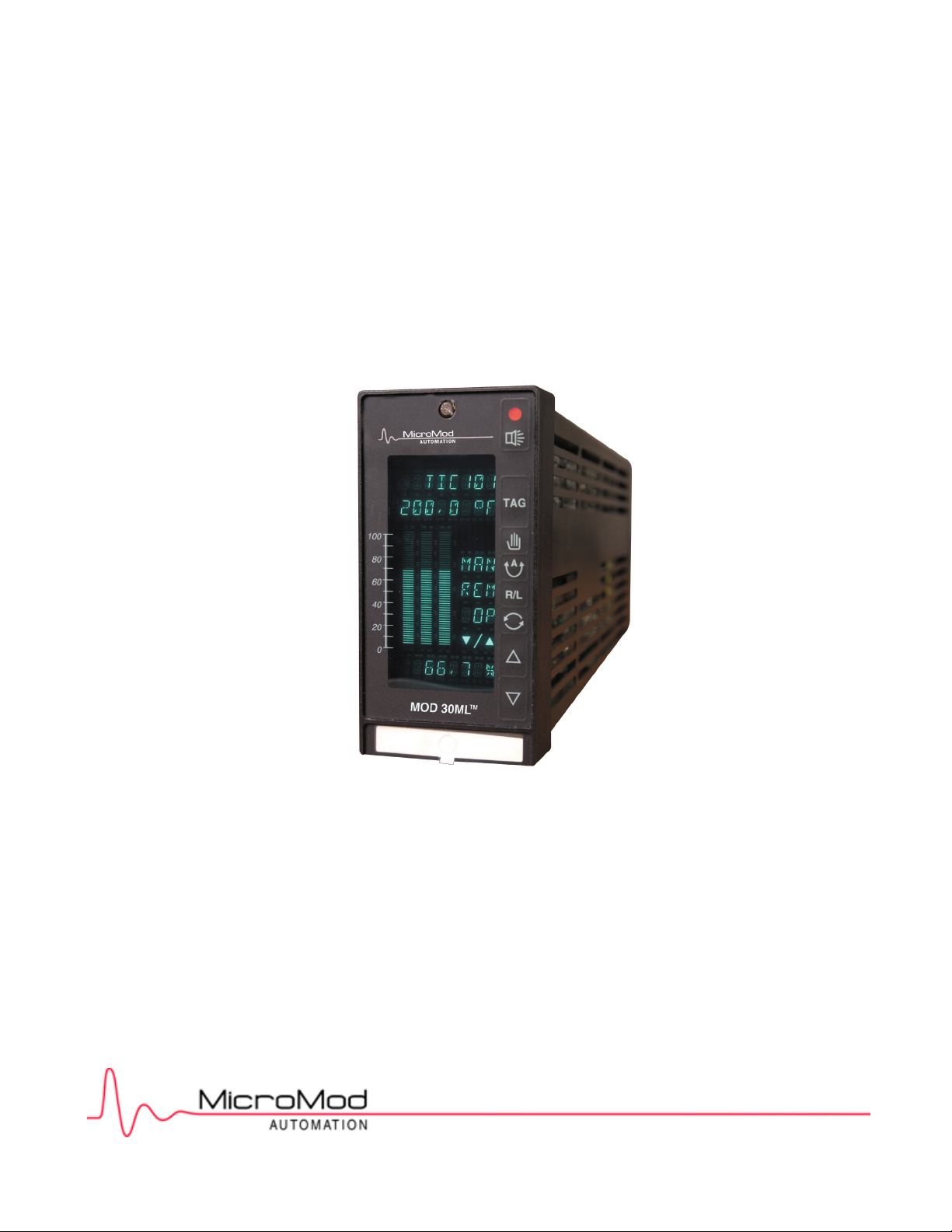
MOD 30ML™ Multiloop Controller Operation
General Operation and Setup using
1800R MOD 30ML™
Identity Module (Version 2)
Page 2

MicroMod Automation, Inc.
The Company
MicroMod Automation is dedicated to improving customer efficiency by providing the most cost-effective, application-specific process solutions
available. We are a highly responsive, application-focused company with years of expertise in control systems design and implementation.
We are committed to teamwork, high quality manufacturing, advanced technology and unrivaled service and support.
The quality, accuracy and performance of the Company's products result from over 100 years experience, combined with a continuous
program of innovative design and development to incorporate the latest technology.
Use of Instructions
Ì Warning. An instruction that draws attention to the risk of
injury or death.
Note. Clarification of an instruction or additional
information.
q Caution. An instruction that draws attention to the risk of
the product, process or surroundings.
Although Warning hazards are related to personal injury, and Caution hazards are associated with equipment or property damage, it
must be understood that operation of damaged equipment could, under certain operational conditions, result in degraded process
system performance leading to personal injury or death. Therefore, comply fully with all Warning and Caution notices.
Information in this manual is intended only to assist our customers in the efficient operation of our equipment. Use of this manual for
any other purpose is specifically prohibited and its contents are not to be reproduced in full or part without prior approval of MicroMod
Automation, Inc.
Licensing, Trademarks and Copyrights
MOD 30 and MOD 30ML are trademarks of MicroMod Automation, Inc.
MODBUS is a trademark of Modicon Inc.
Health and Safety
To ensure that our products are safe and without risk to health, the following points must be noted:
The relevant sections of these instructions must be read carefully before proceeding.
1. Warning Labels on containers and packages must be observed.
2. Installation, operation, maintenance and servicing must only be carried out by suitably trained personnel and in accordance with the information
given or injury or death could result.
3. Normal safety procedures must be taken to avoid the possibility of an accident occurring when operating in conditions of high
4. pressure and/or temperature.
5. Chemicals must be stored away from heat, protected from temperature extremes and powders kept dry. Normal safe handling procedures must be
used.
6. When disposing of chemicals, ensure that no two chemicals are mixed.
Safety advice concerning the use of the equipment described in this manual may be obtained from the Company address on the back
cover, together with servicing and spares information.
All software, including design, appearance, algorithms and source
codes, is copyrighted by MicroMod Automation, inc. and is owned by
MicroMod Automation or its suppliers.
i Information. Further reference for more detailed
information or technical details.
Page 3

MOD 30ML Operation
CONTENTS
CONTENTS
Page
SECTION 1 - INTRODUCTION
1.1 FEATURES.......................................................................................................................... 1-1
1.2 DESCRIPTION .................................................................................................................... 1-1
1.2.1 Functionality......................................................................................................................... 1-1
1.2.2 Configuration........................................................................................................................ 1-2
1.2.3 Operation ............................................................................................................................. 1-2
1.2.4 Process I/O .......................................................................................................................... 1-2
1.2.5 Communications (requires Application Builder Software suport) ......................................... 1-2
1.3 RELATED DOCUMENTATION............................................................................................ 1-3
1.4 VERSION IDENTIFICATION ............................................................................................... 1-4
SECTION 2 - SETUP
2.1 GENERAL PREPARATIONS............................................................................................... 2-1
2.2 DEVICE STATES................................................................................................................. 2-2
2.3 USING MEMORY MODULE ................................................................................................ 2-2
2.3.1 DOWNLOAD From Memory Module to Main Database ................................................... 2-2
2.3.2 UPLOAD From Main Database to Memory Module.......................................................... 2-3
2.4 DEVICE DISPLAYS ............................................................................................................. 2-3
2.5 TEMPLATE SETUP ............................................................................................................. 2-10
SECTION 3 - OPERATION
3.1 INTRODUCTION ................................................................................................................. 3-1
3.2 FRONT PANEL.................................................................................................................... 3-1
3.3 CONTROL KEYS................................................................................................................. 3-3
3.4 ALPHANUMERIC DISPLAYS.............................................................................................. 3-4
3.4.1 Line 1 and Line 2 Displays................................................................................................... 3-4
3.4.2 Line 3 Displays..................................................................................................................... 3-4
3.4.3 Line 4 Displays..................................................................................................................... 3-5
3.4.4 Line 5 Displays..................................................................................................................... 3-6
3.4.5 Line 6 Display ...................................................................................................................... 3-7
3.5 BAR DISPLAYS ................................................................................................................... 3-7
3.6 ALARM INDICATOR............................................................................................................ 3-7
3.7 UP / DOWN KEY OPERATION ........................................................................................... 3-8
3.7.1 Ramping .............................................................................................................................. 3-8
3.7.2 Data Entry............................................................................................................................ 3-8
3.8 SELECTING A CONTROL LOOP FOR DISPLAY ............................................................... 3-9
3.9 SINGLE LOOP OPERATION IN AUTOMATIC MODE ........................................................ 3-10
3.9.1 Single Loop Automatic Operation with Local Set-Point........................................................ 3-10
3.9.2 Single Loop Automatic Operation with Remote Set-Point.................................................... 3-11
3.9.3 Single Loop Automatic Operation with Ratio and Bias ........................................................ 3-12
3.9.4 Single Loop Automatic Operation with Feed Forward ......................................................... 3-13
3.10 SINGLE LOOP AUTO/MANUAL TRANSFER ..................................................................... 3-14
3.10.1 Control Loop with Reset....................................................................................................... 3-14
3.10.2 Control Loop without Reset.................................................................................................. 3-15
3.11 SINGLE LOOP OPERATION IN MANUAL .......................................................................... 3-16
3.12 CASCADE OPERATION ..................................................................................................... 3-17
3.12.1 Cascade Control, Slave in Manual....................................................................................... 3-17
3.12.2 Cascade Control, Slave in Auto ........................................................................................... 3-18
i
Page 4

MOD 30ML Operation
CONTENTS
CONTENTS (Cont’d)
Page
3.13 ALARMS............................................................................................................................... 3-19
3.13.1 Alarm Trip points .................................................................................................................. 3-19
3.13.2 Alarm Priority........................................................................................................................ 3-19
3.13.3 Monitoring and Acknowledging Alarms ................................................................................ 3-20
3.13.4 Alarm Display Viewing Sequence......................................................................................... 3-25
3.14 TUNING................................................................................................................................ 3-25
3.14.1 Password.............................................................................................................................. 3-25
3.14.2 Alarm Parameters ................................................................................................................ 3-26
3.14.2 Control Parameters .............................................................................................................. 3-27
3.15 STARTUP............................................................................................................................. 3-29
3.15.1 Startup Without Set-Point Tracking ...................................................................................... 3-29
3.15.2 Startup With Set-Point Tracking ........................................................................................... 3-29
APPENDIX A - EVENT CODES AND TRANSITIONS
A.1 EVENT TRANSITIONS (2-).................................................................................................. A-1
A.2 EVENT CODE, EXPANDED DESCRIPTION....................................................................... A-1
A.2.1 IF - Interface Block Events................................................................................................ A-1
A.2.2 SE - System Event Block Events ...................................................................................... A-3
A.2.3 LP - Loop Block Events..................................................................................................... A-3
A.2.4 ICN - ICN Communication Block Events........................................................................... A-3
A.2.5 MSC - MSC Communication Block Events ....................................................................... A-4
A.2.6 DIM - Digital Input Module Block Events........................................................................... A-4
A.2.7 DO, WDO, DDO - Digital Output Module Block Events .................................................... A-4
A.2.8 VCIM, TIM, CJIM, WRIM - Analog Input Module Block Events......................................... A-4
A.2.9 AOM - Analog Output Module Block Events ..................................................................... A-5
A.2.10 AI - Analog Input Block Events ......................................................................................... A-5
A.2.11 DI - Digital Input Block Events .......................................................................................... A-5
A.2.12 LN - Linearization Block Events ........................................................................................ A-5
A.2.13 PID - PID Block Events ..................................................................................................... A-5
A.2.14 PAD - Process Alarm Display Block Events...................................................................... A-6
A.2.15 AIN - Built-in Analog Input Block Events ........................................................................... A-6
A.2.16 AOUT - Built-in Analog Output Block Events .................................................................... A-6
ii
Page 5

MOD 30ML Operation
CONTENTS
ILLUSTRATIONS
Figure Page
2-1 Display Resources ............................................................................................................... 2-3
2-2 Display Block (DISP), Edit display, page 1 .......................................................................... 2-7
3-1 Controller Front Panel .......................................................................................................... 3-2
TABLES
Table Page
2-1 Device Status....................................................................................................................... 2-4
2-2 Device Setup ....................................................................................................................... 2-7
2-3 Device I/O Status ................................................................................................................. 2-8
2-4 Device Events...................................................................................................................... 2-9
2-5 About This Device................................................................................................................ 2-9
2-6 Template Configuration........................................................................................................ 2-10
2-7 System Template Configuration........................................................................................... 2-11
2-8 User Compound Template Configuration............................................................................. 2-13
A-1 Event Transition Messages and Descriptions...................................................................... A-1
iii
Page 6

MOD 30ML Operation
CONTENTS
iv
Page 7

1.1 FEATURES
The following features are included with the basic instrument:
• Built-in single loop PID Control or Single Station Cascade Strategies,
• Two Isolated universal analog inputs standard
• Two analog outputs standard
The following features are options to the basic instrument:
• Up to 11 additional single point, individually isolated local process I/O
• Redundant, removable NOVRAM backs up configuration and current process parameters
The following features require the support of the instrument configuration software:
MOD 30ML Operation
INTRODUCTION
1
INTRODUCTION
• Serial communications: Instrument Communications Network, RS-232 and RS-485
Modbus standard
• Up to 100 additional discrete remote I/O points through a Remote I/O Interface module
• Logic, advanced and sequential control functions
• Display scripting functions
• Complete configuration control using graphics based blocks and connections
1.2 DESCRIPTION
This microprocessor based 3x6 multiloop controller is designed to meet your process control
needs whether you use it for loop indication or to implement advanced process strategies.
The controller can display and control continuous process variables such as temperature,
pressure, liquid level, or flow and has the ability to perform digital logic functions.
1.2.1 Functionality
The instrument provides continuous control functions such as PID, feedforward, set-point and
output tracking, external feedback, set-point and output limiting, in addition to logic and I/O
functions. As many as six PID or 4 cascade loops can be run in a single controller with a total
loop processing time of 250 milliseconds. Using on-board I/O, PID control loops can be
executed as fast as 100 milliseconds.
Using the configuration software for setup, the instrument can run Sequence Blocks based on
a drum programmer design with up to 100 inputs, 80 steps and 30 outputs per block; blocks
can be cascaded for larger sequences. Sequence Blocks allow forward and backward
stepping, unlimited branching and outputs configurable for any data type (discrete, floating
point, integer, time, date, ASCII or HEX).
The instrument has 64K of non-volatile RAM which contains the user database and all current
process and operating parameters. The optional Portable Memory Module provides 64K of
1-1
Page 8

MOD 30ML Operation
INTRODUCTION
redundant, removable non-volatile RAM which backs up the configured database and, if left
on the instrument during operation, current process data. Nonvolatile RAM memory has a
typical data retention of 10 years.
1.2.2 Configuration
Configuration of the instrument is accomplished via one of two methods. For applications
using single loop PID, single station cascade, feedforward and ratio/bias, canned strategies
and their faceplates are easily implemented through the instruments front face displays and
operator push buttons. Template configuration uses easy-to-read English prompts.
For more complex applications, beyond those offered with the basic instrument, configuration
is accomplished through the icon-based Application Builder Software which is used to create,
edit, save, download and document the data base in a graphic environment. Downloading
instrument configurations can be done via ICN, or via Modbus over RS-232 or a 4-wire RS485 network. This software is also used to prepare runtime operation files for a computer
using the ICN or Modbus protocol. Local display and operations can also be provided using
the 2021W Local Control Panel over the ICN.
1.2.3 Operation
The instrument can display and control a variety of process variables such as temperature,
pressure, flow, and liquid level. In addition to continuous display of the process variable for a
selected loop, the front panel display shows the operating set-point, control output, process
alarm indication, loop tag name, and status indication of control mode and set-point source.
Front panel keys provide for operational activities such as auto/manual switching,
remote/local set-point switching, manual output adjustment, process alarm and diagnostic
message acknowledgment, and enabling communication with a host device.
1.2.4 Process I/O
MODBUS
serial communications. Signal conditioning, fail-safe and power fail/recovery parameters may
reside in each individual module.
Analog I/O Modules
Analog input modules provide high-resolution signal conditioning performed in the module.
Process signals including RTD and thermocouple are connected directly to the rear terminations
without requiring transmitters or transducers for signal conversion. A single module supports all
thermocouple types with upscale burnout detection. Cold junction compensation is also provided.
One current input module type supplies isolated loop power for 2-wire transmitters. Other input
types include volt, millivolt, 2- and 3-wire RTD with upscale burnout detection and current input
Two isolated universal analog inputs and two current outputs
are standard. Each analog input can receive direct connection
of either milliamp (2-wire or non 2-wire), millivolt, volt, RTD
thermocouple or resistance. Inputs have full galvanic
isolation. Both analog outputs can be user set between span
limits of 0 and 50 milliamps.
In addition there can be up to eleven process I/O and
communication modules. Plug in modules include various
types of analog input, analog output, digital input, digital
output, Instrument Communication Network (ICN) and
1-2
Page 9

MOD 30ML Operation
without loop power. The analog output module supplies 4-20mA or 0-20mA. All analog I/O
modules are individually, optically isolated to 250Vrms continuous.
Digital I/O
Digital I/O is selected by the user through use of digital I/O modules. Options include both isolated
and non-isolated modules. Solid state relay versions offer high isolation voltage capability. Nonisolated modules are compatible with TTL logic levels and provide the ability to interface between
similar modules without the need for an external power supply. The Mechanical Relay output
module supports Form A, Form B and Form C relays.
Remote I/O (requires Application Builder Software support)
Remote I/O input and output modules expand the I/O capability to a total of 100 discrete points.
The module communicates over the Remote I/O Network, an RS-485 fieldbus which connects to
the instrument via a 2020N RIO module. The RIO module does not need to use a
communications position leaving those two positions open for communications modules. Refer to
IB-23C601.
1.2.5 Communications (requires Application Builder Software support)
Two serial communications channels on each instrument allow up to two independent
networks to function simultaneously. The first channel is built-in and is selectable for either
Instrument Communications Network (ICN), RS-232 Modbus or RS-485 Modbus. The second
channel uses an ICN, RS-232 Modbus or RS-485 (2-wire or 4-wire forms) module.
1.3 RELATED DOCUMENTATION
Information about this instrument and its configuration
can be found in:
INTRODUCTION
• IB-1800R-APP – Data Base Reference for MOD 30ML Functions
• IB-23G600 – Data Base Reference for Logic Functions - Book 1
• IB-23G602 – Data Base Reference for Logic Functions - Book 2
• IB-23G601 – Data Base Reference for Advanced Control Functions
• IB-23H141 – User’s Guide for Application Builder Software (2006S)
• IB-23H120 – User’s Guide for PC-30 Instrument Interface Software for MOD 30 and
MODCELL Instruments
Information about this instrument and its installation
• IB-1800R-INS – Installation, MOD 30ML
• IB-1800R-M30 – MOD 30 Replacement Installation, MOD 30ML
• IB-23C601 – Installation, Remote I/O Modules
can be found in:
1-3
Page 10

MOD 30ML Operation
INTRODUCTION
1.4 VERSION IDENTIFICATION
To verify the version level of the instrument, check the version number marked on the PROM
label of the identity module. The firmware version is a digit in the catalog number as follows:
Catalog Number Description for 2004P
MOD 30ML PANEL-MOUNT
Base Controller
Standard bezel
Narrow bezel (Foxboro replacement version)
Approvals
General Purpose
CE (European Community destinations only)
FM/CSA Class 1 Division 2 A,B,C,D
Power Supply
24V dc
85 to 265V ac
Enclosure
Standard terminations
Standard terminations, NEMA 4
Standard terminations, NEMA 4 with conformal
coating
Not Used 0
Design Model
General Purpose, FM/CSA approval
European Approval (CE Certification - for
European Community destinations)
Programming / Special Features
None
Sample Number 1800PZ10102C (Product is serialized)
Version number identification is also available in the *DEVICE* ABOUT displays as
described in setup Table 5.
06
1800RZ
1801RZ
07-08 09 10 11 12 13 14 15
10
12
21
0
1
0
3
4
A
B
S T D
1-4
Page 11
! CAUTION Be sure the process can be maintained in a safe condition before turning on
instrument power. The instrument may not be configured to meet the specific
requirements of the process until setup has been performed.
2.1 GENERAL PREPARATIONS
After installation is complete, begin setup by preparing the instrument as follows:
1. Set the SCRV/RUN switch under the front face to the RUN position. If a Memory Module is
present, see Using The Memory Module to load a database stored to a memory module.
2. At ac power source, turn on power to instrument. When power is on, the front panel
display illuminates showing either a default database (as shipped from factory) or some
other successfully loaded database.
MOD 30ML Operation
SETUP
2
SETUP
Default Database
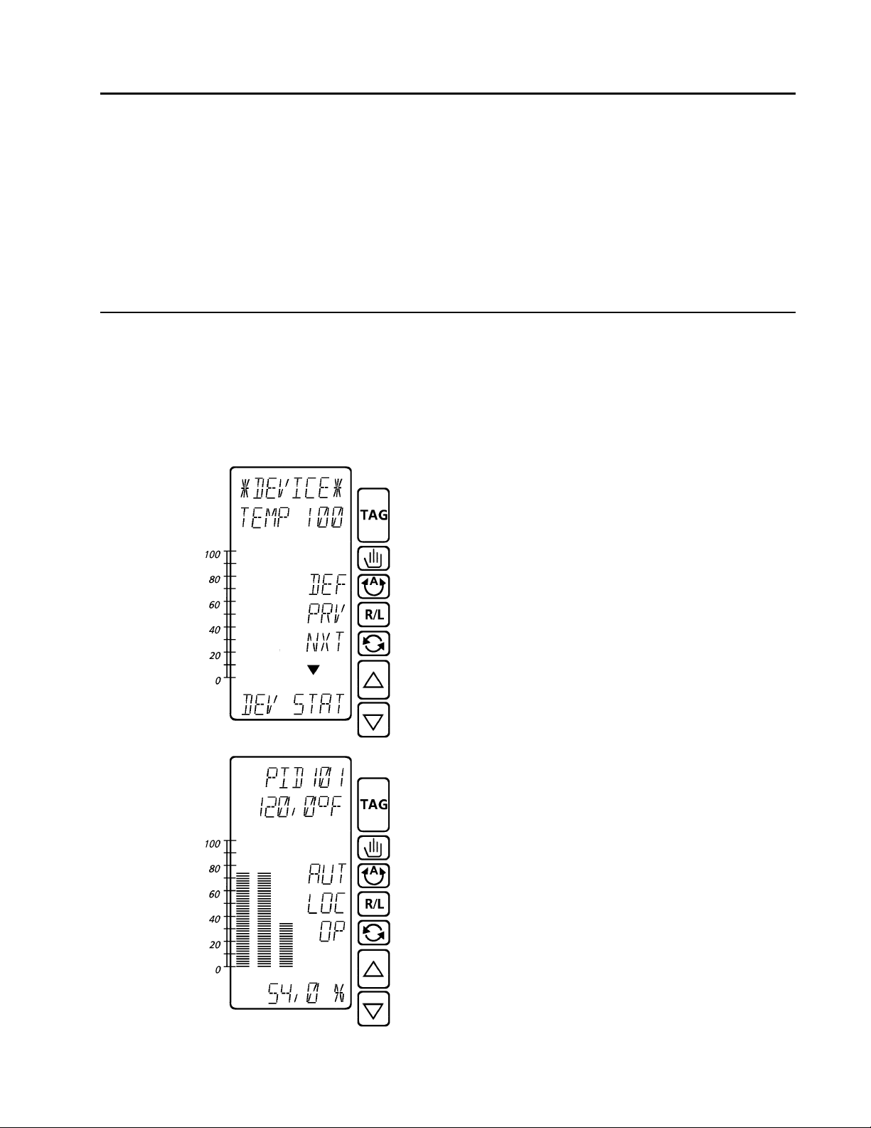
If the instrument does not have a valid user database, the
first DEVICE display (device status entry point) will
appear and any diagnostic indications will be enabled.
The default device tag is TEMP 100.
The device display shows the state of the instrument on
line 3 (see Device States).
The keys labeled NXT (next step) and PRV (previous
step) move you through the entry points for the setup
tables while the down arrow ∇ indicates the down arrow
key can be used to enter a step
the instrument state is RUN, the TAG key will switch you
to the first user runtime display.
Valid User Database Loaded
If the instrument has a valid user database, the power up
display (Device, Previous or User) will appear and any
enabled diagnostics, such as for power up and power
down, will be indicated. You can prepare the instrument
for setup by acknowledging these diagnostics and
making any necessary adjustments to your operating
conditions from the user display (see Operation for
general operation).
Return to the DEVICE display by pressing and holding
the TAG key.
(see Device Displays). If
2-1
Page 12

MOD 30ML Operation
SETUP
3. Press the alarm key to get the list of unacknowledged and active
acknowledged alarms and diagnostics (Appendix A lists all reportable
diagnostics and events). Press the key labeled UAK to acknowlege the
alarm (changes to ACT). Press the alarm key again to view the next
4. If a previous shutdown condition exists, it must be acknowledged from the device status
shutdown displays (Step 1B of Device Status Table 1); otherwise, template configuration
and memory module downloads will fail.
alarm and repeat until the end where you can return to the device display
(see Alarms in Section 3.13).
2.2 DEVICE STATES
The instrument state is indicated by a three letter code on line 3 of the device displays.
Except for Local Hold, installation of a template will change the instrument state to Run.
DEF The Default state means the instrument has no valid user database and is running an
internal database to maintain communications and system activities.
HLD The Hold state indicates the instrument has a valid user database and is performing
overhead functions only - no loops are running.
LHD The Local Hold state indicates the SCRV/RUN switch is in SCRV and the instrument
is in the Local Hold state.
RUN The Run state means the instrument has a valid user database and is running that
database.
2.3 USING THE MEMORY MODULE
The backup memory module is used to maintain a mirror image of the 64K instrument
database. A small part of this image is reserved for shutdown information and serves as a
valuable diagnostic tool. The module may be write protected to protect shutdown and other
information.
2.3.1 DOWNLOAD From Memory Module to Main Database
Follow this procedure to load a database stored in a memory module.
1. Set Memory Module switches to "read/write" or "Read Only" and "Normal".
2. Power up the instrument.
The instrument automatically attempts a download from the memory module during
power-up. If the module database is 'good' (configured, version compatible, has valid
checksums, no ICN or comm port mismatch), the 'download on warm start' attribute is
YES and the instrument did not have a previous shutdown fault, the transfer will occur.
The download on warm start attribute allows a user to (for instance) write protect a
module with cold start values in it and have it download only on cold start.
2-2
Page 13

2.3.2 UPLOAD From Main Database to Memory Module
Follow this procedure to store a database to a memory module.
1. Set Memory Module switches to "read/write" and "module load".
2. Power up the instrument.
3. UPLOAD? is displayed by the instrument. To upload to the memory module, press either
the up or down arrows and press the key labeled ENT for enter. The default database is
run with instrument state equal to UPLOAD.
4. UPL DONE SET WP? is displayed by the instrument. The module is now loaded with the
instrument database. If you want to write protect the module, select YES and enter (UPL
DONE, WP DONE). Skip this command and go to the next step if you do not want to
write protect the module.
5. Power down the instrument. Instrument state cannot be changed until power is removed
and module switch is placed in "Normal".
6. Set Memory Module switches to "read/write" or "Read Only" and "Normal".
7. Power up the instrument.
2.4 DEVICE DISPLAYS
The device displays consist of the following main groups and related instrument information.
They are presented in the order they appear as you step through the top level of device
displays. Follow the steps as described in each table to view status information or change
how the instrument operates. Only Table 6 and its supporting setup tables are used to create
a runtime configuration.
DEVice STATus Table 1* State Commands, Shutdown information and
acknowledgement, Status Commands, Execution Times
and Current Time, Date and Day.
device SETUP Table 2 Communication Parameters and Password Entry.
device I/O status Table 3* Built-in and Single Point Input/Output Status, signal
values and Auto/Manual selection.
device EVENTS Table 4 List of events in the Event Queue. See Appendix A.
ABOUT this device Table 5 Current Version of Firmware and Display.
TEMPLATE Table 6* Load template defaults, Edit templates and Install
templates. See Template Setup.
* These require a Configure Password, if it is enabled, to gain entry.
* NOTE: Step levels changes are indicated by alternating numbers and letters. For
example, Step 1A is the first step down one level from Step 1. Shaded areas
alternate between significant subjects within the groups.
Use the keys labeled NXT (next step) and PRV (previous step) to move through the entry
points for the setup tables and use the down arrow ∇ key to enter the first step of each table.
MOD 30ML Operation
SETUP
2-3
Page 14

MOD 30ML Operation
SETUP
Table 1. Device Status
Step Step Description Line 1 Line 2 Line 6 Entry Description
1 Device Status
∇ moves down to Step 1A
NXT goes to Step 2 (Setup)
PRV goes to Step 6 (Template)
1A
Device Status State Command
∇ ∆ changes state on line 6
ENT enters device state
NXT, PRV change step
1B
Device Status Shutdown (Entry)
∇ moves down to Step 1B1.
1B1 Shutdown Page 1
NXT, PRV change step
1B2 Shutdown Page 2
NXT, PRV change step
1B3 Shutdown Page 3
NXT, PRV change step
1B4 Shutdown Page 4
NXT, PRV change step
1B5 Shutdown Page 5
∇ ∆ select YES/NO
NXT, PRV change step
1B6 Device Status Shutdown (Exit)
∆ moves up to Step 1B
NXT, PRV change step
1C Device Status Commands (Entry)
∇ moves down to Step 1C1
1C1 Clear Queue Command
∇ ∆ select YES/NO, ENT enters.
NXT, PRV change step
1C2 Clear Maximum Scan Times
∇ ∆ select YES/NO, ENT enters.
NXT, PRV change step
1C3 Global Acknowledge Command
∇ ∆ select YES/NO, ENT enters.
NXT, PRV change step
*DEVICE* NOT CFGD
or
DEV TAG
DEV STAT INSTATE DEFAULT
DEV STAT SHUTDOWN NO
SYSPI 1 XXXXXXXX
SYSPI 2 HH:MM:SS MM/DD/YY
SYSPI 3 XXXXXXXX XXXXXXXX
SYSPI 4 XXXXXXXX XXXXXXXX
SYSPI 5 ACK SD NO
SYSPI 6 DEV STAT
DEV STAT COMMANDS
COMMANDS CLR Q NO
COMMANDS CLR MT NO
COMMANDS ACK ALL NO
DEV STAT
YES
See Table 2 for step 2 (Setup)
See Table 6 for step 6 (Template)
These steps are protected by the
CONFIG password. Enter proper
password, if used, to move down.
DEFAULT (DEF)
HOLD (HLD)
HOLD WST (Hold with Warm Start)
RUN (RUN)
RUN WST (Run with Warm Start)
see Device States.
Shutdown status is a debug tool
used to read specific instrument
registers. NO means no shutdown
is present. YES indicates a
shutdown. Record the information
on pages 1 to 5 and report them
when requesting a repair.
Line 1 can be: Sxrrrr where
x (shutdown) = Y (yes) or N (no) and
rrrr = WDOG (Watchdog),
SPI (Spurious interrupt),
BMCK (Bad main database checksum),
BDCK (Bad default database
checksum), BECK (Bad EEPROM
checksum), BRAM (Bad RAM), DMA
(DMA error), IOSO (IO Stack Overrun),
FPCF (Faceplate comm. failure).
Time and date of shutdown or
of acknowledge shutdown.
Record number.
Record number.
Yes acknowledges shutdown,
restarts instrument and clears
registers. If acknowledge fails,
instrument will not restart.
Use to clear system event queue.
Press ENT after selecting YES.
Use to clear maximum scan times
for all scan groups.
Press ENT after selecting YES.
Use to send global acknowledge
command causing all diagnostics,
alarms and notification/request
messages to be acknowledged.
Press ENT after selecting YES.
2-4
Page 15

MOD 30ML Operation
Table 1. Device Status (Cont’d)
Step Step Description Line 1 Line 2 Line 6 Entry Description
1C4 Reset Command
∇ ∆ select YES/NO, ENT enters.
NXT, PRV change step
1C5 Kill Command
∇ ∆ select YES/NO, ENT enters.
NXT, PRV change step
1C6 Delete Main Database Command
∇ ∆ select YES/NO, ENT enters.
NXT, PRV change step
1C7 Restore Main Database Command
∇ ∆ select YES/NO, ENT enters.
NXT, PRV change step
1C8 Device Status Commands (Exit)
∆ moves up to Step 1C
1D Device Execution Times (Entry)
∇ moves down to Step 1D1
1D1 Scan 1 Execution Time
NXT, PRV change step
1D2 Scan 2 Execution Time
1D3 Scan 3 Execution Time
1D4 Scan 4 Execution Time
1D5 Scan 5 Execution Time
1D6 Scan 6 Execution Time
1D7 Scan 7 Execution Time
1D8 Scan 8 Execution Time
1D9 Scan 9 Execution Time
1D10 Scan 1 Filtered Execution Time
1D11 Scan 2 Filtered Execution Time
1D12 Scan 3 Filtered Execution Time
1D13 Scan 4 Filtered Execution Time
1D14 Scan 5 Filtered Execution Time
1D15 Scan 6 Filtered Execution Time
1D16 Scan 7 Filtered Execution Time
1D17 Scan 8 Filtered Execution Time
1D18 Scan 9 Filtered Execution Time
COMMANDS RESET NO
COMMANDS KILL NO
COMMANDS DEL MAIN NO
COMMANDS RES MAIN NO
COMMANDS DEV STAT
DEV STAT XTIMES
XTIMES T1 IMMED 0:00.000
XTIMES T2 IMMED 0:00.000
XTIMES T3 IMMED 0:00.000
XTIMES T4 IMMED 0:00.000
XTIMES T5 IMMED 0:00.000
XTIMES T6 IMMED 0:00.000
XTIMES T7 IMMED 0:00.000
XTIMES T8 IMMED 0:00.000
XTIMES T9 IMMED 0:00.000
XTIMES T1 FILTD 0:00.000
XTIMES T2 FILTD 0:00.000
XTIMES T3 FILTD 0:00.000
XTIMES T4 FILTD 0:00.000
XTIMES T5 FILTD 0:00.000
XTIMES T6 FILTD 0:00.000
XTIMES T7 FILTD 0:00.000
XTIMES T8 FILTD 0:00.000
XTIMES T9 FILTD 0:00.000
Use to complete tasks and then
perform a power-up.
Press ENT after selecting YES.
Use to perform an immediated
power-up.
Press ENT after selecting YES.
Use to mark the main database as
bad and set the instrument state to
DEFAULT.
Press ENT after selecting YES.
Use to mark the main database as
good (in case delete was issued by
mistake) and if verified as good will
attempt to set the instrument state
to RUN.
Press ENT after selecting YES.
Scan groups 1 through 5 are user
defined intervals for loops. The
fastest group has the highest
priority. The lower numbered group
has a higher priority if the interval is
the same.
Scan group 6 is a system group
Scan groups 7 to 9 are
communications groups.
Recent millisecond scan time for
the associated scan group.
“
“
“
“
“
“
“
“
Average millisecond scan time for
the associated scan group
(updates after group executes).
“
“
“
“
“
“
“
“
SETUP
2-5
Page 16

MOD 30ML Operation
SETUP
Table 1. Device Status (Cont’d)
Step Step Description Line 1 Line 2 Line 6 Entry Description
1D10 Scan 1 Maximum Execution Time
1D11 Scan 2 Maximum Execution Time
1D12 Scan 3 Maximum Execution Time
1D13 Scan 4 Maximum Execution Time
1D14 Scan 5 Maximum Execution Time
1D15 Scan 6 Maximum Execution Time
1D16 Scan 7 Maximum Execution Time
1D17 Scan 8 Maximum Execution Time
1D18 Scan 9 Maximum Execution Time
1D19 Base Scan Time
1D20 Scan Idle Time
1D21 Device Status Xtimes (Exit)
∆ moves up to Step 1D
1E
1F
1G
1H Device Status (Exit)
Device Status Time
∇ ∆ changes a number
NXT, PRV flash to change position
ENT enters.
NXT, PRV change step
Device Status Date
∇ ∆ changes a number
NXT, PRV flash to change position
ENT enters.
NXT, PRV change step
Device Status Day
∇ ∆ changes day ENT enters.
NXT, PRV change step
∆ moves up to Step 1
XTIMES T1 MAX 0:00.000
XTIMES T2 MAX 0:00.000
XTIMES T3 MAX 0:00.000
XTIMES T4 MAX 0:00.000
XTIMES T5 MAX 0:00.000
XTIMES T6 MAX 0:00.000
XTIMES T7 MAX 0:00.000
XTIMES T8 MAX 0:00.000
XTIMES T9 MAX 0:00.000
XTIMES BASE SCN 0:00.050
XTIMES IDLE TM 0:00.039
XTIMES DEV STAT
DEV STAT TIME HH:MM:SS
DEV STAT DATE DD:MM:YY
DEV STAT DAY 3
DEV STAT *DEVICE*
Maximum millisecond scan time for
the associated scan group since
entering the current instrument
state.
“
“
“
“
“
“
“
“
Average millisecond of processor
time between base scan ticks.
00:00:00.050, unless
overconfigured.
Average millisecond of unused
processor time between base scan
ticks.
Current time. The instrument
maintains this time even when off.
Always keep set to current time.
Current date. The instrument
maintains this date even when off.
Always keep set to current date.
Current day (Sunday = 1, Saturday
= 7). The instrument maintains this
day even when off. Always keep
set to current day.
Table 2. Device Setup
Step Step Description Line 1 Line 2 Line 6 Entry Description
2 Device Setup
∇ moves down to Step 2A
NXT goes to Step 3 (I/O)
PRV goes to Step 1 (Status)
*DEVICE* NOT CFGD
or
DEV TAG
SETUP
See Table 3 for step 3 (I/O)
See Table 1 for step 1 (Status)
2-6
Page 17

MOD 30ML Operation
SETUP
Table 2. Device Setup (Cont’d)
Step Step Description Line 1 Line 2 Line 6 Entry Description
2A Setup Built-in Communications
∇ moves down to Step 2A1 if
jumper is on ICN or 2A3 if jumper
is on RS232, or RS485.
NXT, PRV change step
2A1 Set ICN Address
∇ ∆ changes number, ENT enters.
NXT, PRV change step
2A2 Set ICN Status Active
∇ ∆ selects YES/NO, ENT enters.
NXT, PRV change step
2A3 Set Modbus Address
∇ ∆ changes number, ENT enters.
NXT, PRV change step
2A4 Set Modbus Baud Rate
∇ ∆ changes rate, ENT enters.
NXT, PRV change step
2A5 Set Modbus Parity
∇ ∆ changes parity, ENT enters.
NXT, PRV change step
2A6 Set Modbus Stopbits
∇ ∆ changes stopbits, ENT enters.
NXT, PRV change step.
2A7 Set Modbus Status Active
∇ ∆ selects YES/NO, ENT enters.
NXT, PRV change step
2A8 Setup Communication (Exit)
∆ moves up to Step 2A.
2B Password
∇ moves down to Step 2B1
NXT, PRV change step
2B1 Password
∇ ∆ changes number, ENT enters
and changes step
2B2 Current Level
ENT goes to step 2B.
2C Setup Device (Exit)
∆ moves up to Step 2
NXT, PRV change step
NOTE: Built-in address cannot be changed if the ICN or MSC block's address within the Main Database is set to a specific number (not
set to "Any"). In order to change the address, the Main Database must first be deleted or a new Database must be downloaded which
has the ICN or MSC block's address configured to "Any".
SETUP BI COMM
BI ICN 1 ADDRESS 15
BI ICN 1 ENABLED
ENABLE?
BI MSC 1 ADDRESS 247
BI MSC 1 BAUDRATE 9600
BI MSC 1 PARITY NONE
BI MSC 1 STOPBITS 1
BI MSC 1 ENABLED
ENABLE?
SETUP
SETUP PASSWORD
PASSWORD 0
CURRENT LEVEL TUNE
SETUP *DEVICE*
NO
NO
Except for the address, built-in
communication parameters can be
changed while the instrument state
is RUN. Address changes require
that the instrument be in the
DEFAULT state (See Note) or with
port status set off after power up
and SCRV switch set (LHD or DEF
state).
ICN address can be 0 to 15. Can
be set when the instrument is in the
DEFAULT state (See Note
Communication jumper set on the
ICN position.
ENABLED = Active. To make
inactive, power up with SCRV
switch set. ENABLE? = Inactive.
Select YES to make it active.
Modbus address can be 1 to 247.
Can be set when the instrument is
in the DEFAULT state.
Communication jumper set on
RS232, or RS485 position.
150, 300, 600, 1200, 2400, 4800,
9600, 19200, 38400
None. Odd, Even
1, 2
ENABLED = Active. To make
inactive, power up with SCRV
switch set. ENABLE? = Inactive.
Select YES to make it active.
Enter a number to change access
to the instrument to None, Tune or
Configure.
NONE an invalid password.
TUNE tune access.
CONFIG configuration access.
).
2-7
Page 18

MOD 30ML Operation
SETUP
Table 3. Device I/O Status
Step Step Description Line 1 Line 2 Line 6 Entry Description
3 Device I/O
∇ moves down to Step 3A
NXT goes to Step 4 (Events)
PRV goes to Step 2 (Setup)
3A Built in Analog Input 1
AUT, MAN change mode
NXT, PRV change step
3B Built in Analog Input 2
Same as Input 1
3C Built in Analog Output 1
Same as Input 1
3D Built in Analog Output 2
Same as Input 1
3E Module Position 1
Same as Input 1
3F Module Position 2
Same as Input 1
3G Module Position 3
Same as Input 1
3H Module Position 4
Same as Input 1
3I Module Position 5
Same as Input 1
3J Module Position 6
Same as Input 1
3K Module Position 7
Same as Input 1
3L Module Position 8
Same as Input 1
3M Module Position 9
Same as Input 1
3N Module Position 10
Same as Input 1
3O Module Position 11
Same as Input 1
3P Device I/O (Exit)
∆ moves up to Step 3
NXT, PRV change step
*DEVICE* NOT CFGD
or
DEV TAG
BI AIN 1 UNCONFIG
or LABEL
BI AIN 2 UNCONFIG
or LABEL
BI AOUT1 UNCONFIG
or LABEL
BI AOUT1 UNCONFIG
or LABEL
S01 UNCONFIG
or LABEL
S02 UNCONFIG
or LABEL
S03 UNCONFIG
or LABEL
S04 UNCONFIG
or LABEL
S05 UNCONFIG
or LABEL
S06 UNCONFIG
or LABEL
S07 UNCONFIG
or LABEL
S08 UNCONFIG
or LABEL
S09 UNCONFIG
or LABEL
S10 UNCONFIG
or LABEL
S11 UNCONFIG
or LABEL
I/O *DEVICE*
I/O
& VALUE
& VALUE
& VALUE
& VALUE
& VALUE
& VALUE
& VALUE
& VALUE
& VALUE
& VALUE
& VALUE
& VALUE
& VALUE
& VALUE
& VALUE
These steps are protected by the
CONFIG password. Enter proper
password, if used, to move down.
Unconfigured or ‘module’ type and
value shown. Press manual key to
change line 3 to (MAN) and get ∇ ∆
keys. Change value from here.
Leave in auto (AUT) to get field
result.
“
“
“
“
“
“
“
“
“
“
“
“
“
“
2-8
Page 19

MOD 30ML Operation
Table 4. Device Events
Step Step Description Line 1 Line 2 Line 6 Entry Description
4 Device Events (Entry)
∇ moves down to Step 4A
NXT goes to Step 5 (About)
PRV goes to Step 3 (I/O)
4A Block Event Codes
∆ show block event
∇ show event time and type
NXT, PRV change step
4B Block Event Codes (Cont’d)
∆ show block event
∇ show event time and type
NXT, PRV change step
4X Device Events (Exit)
∆ moves up to Step 4.
NXT, PRV change step
*DEVICE* NOT CFGD
INST IN
01/09/96
EVENT Q
01/01/96
EVENTS *DEVICE*
or
DEV TAG
RUN
08:29:34
CLEARED
08:00:00
EVENTS
IF 1
INFOONLY
SE 1
INFOONLY
Line 1 & 2 = event text, Line 3 =
event code, Line 6 = block type and
number. Example shown is
Interface block event (line 3 = code
137, Instrument in RUN state) at
date and time indicated on page 2
(line 3 = msec). See Appendix A
for block event code descriptions.
Use block type (line 6) and event
code (line 3) to find the description.
Same as above for System Event
block event (code 24). See
Appendix A for block event code
descriptions. Use block type (line
6) and event code (line 3) to find
the description.
SETUP
Table 5. About This Device
Step Step Description Line 1 Line 2 Line 6 Entry Description
5 About this Device (Entry)
∇ moves down to Step 5A
NXT goes to Step 6 (Template)
PRV goes to Step 4 (Events)
5A Firmware Version
∆ moves up to Step 5.
NXT, PRV change step
5B Display Version
∆ moves up to Step 5.
NXT, PRV change step
*DEVICE* NOT CFGD
or
DEV TAG
FW VERS I1A 1.0 ISA01
DISP VER 5.1
ABOUT
2-9
Page 20

MOD 30ML Operation
SETUP
2.5 TEMPLATE SETUP
The general procedure for working with a new template configuration is to load defaults, edit
system parameters, edit first user compound, insert any new user compounds and then edit
them. After configuring compounds for single loop PID or Master Slave Cascade control, you
then install the database.
* NOTE INSERT places a new compound in the list AFTER the current compound.
DELETE deletes the current compound. The System compound cannot be
deleted.
Table 6. Template Configuration
Step Step Description Line 1 Line 2 Line 6 Entry Description
6 Device Templates
∇ moves down to Step 6A if
defaults are not loaded otherwise
move down to Step 6B.
NXT goes to Step 1 (Status)
PRV goes to Step 5 (About)
6A Load Template Defaults
∇ moves down to Step 6A1
NXT, PRV change step
6A1
6B Edit Template
6B1 System Compound List
6B2 First User Compound List
6B21 Verify Delete?
6B3 Compound List
Verify Loading Defaults
∇ ∆ select YES (press again ret-
urns you to Step 1 - Changes inst-
rument state & sends you back)
ENT loads defaults from YES and
changes to Step 6B..
∇ moves down to Step 6B1
NXT, PRV change step
∇ ∆ select List, Insert, Edit
ENT to insert (same as step 6B2)
or edit (Step 7A, Table 7).
NXT, PRV change step
∇ ∆ select List, Delete, Insert, Edit
ENT to insert or edit (Step 8A,
Table 8) or delete (Step 6B21).
NXT, PRV change step
∇ ∆ select YES, NO
ENT from NO (Step 6B2) or from
YES to delete (Step 6B3).
NXT, PRV change step
∆ moves up to Step 6B
NXT, PRV change step
*DEVICE* NOT CFGD
or
DEV TAG
LOAD DEFAULTS
VERIFY LOAD
EDIT TEMPLATE
CMP LIST *SYSTEM* LIST
CMP LIST CTAG01 LIST
VERIFY DELETE? NO
CMP LIST
TEMPLATE
These steps are protected by the
CONFIG password. Enter proper
password, if used, to move down.
If the message MAIN DB HAS NO
TEMPLATE appears, a database
loaded by the Application Builder is
present. This main database must
be deleted to access templates.
Use the default template as a
starting point for creation of a data
base. Default values are the basis
for what is shown here.
Defaults provide a System
Compound (Table 7 list defaults in
the line 6 column) and the CTAG01
Compound (Table 8 list defaults in
the line 6 column).
Select LIST to stay at current
compound list level.
Select INSERT to add a user
compound after system compound.
Select EDIT to access the system
compound.
Select LIST to access current user
compounds.
Select DELETE to remove the
current user compound.
Select INSERT to add a user compound after current compound.
Select EDIT to access the current
compound.
No = do not delete
Yes = delete compound
2-10
Page 21

MOD 30ML Operation
Table 6. Template Configuration (Cont’d)
Step Step Description Line 1 Line 2 Line 6 Entry Description
6C Install Template
∇ move down to 6C1
NXT, PRV change step
6C1 Installation of Template
∇ ∆ select YES (press again from
NONE returns you to Step 6C)
ENT loads template and displays
first runtime display.
6C2 Configuration Request Failed
ACK acknowledges failure
message and changes to Step 6B.
6D Template (Exit)
∆ moves up to Step 6
NXT, PRV change step
INSTALL TEMPLATE
INSTALL TYPE NONE
CONFIG REQUEST FAILED
TEMPLATE
Installation verifies and loads the
template making it the active
database (changes state to RUN).
Select NONE to exit installation.
Select INITCOLD to install and
RUN template using a cold start.
Select INITWARM to install and
RUN template using a warm start.
Data base verification failed
because of some inconsistency in
database or an active shutdown
condition. To ACK failure, go to
DEV STAT level and set ACK SD
to Yes (Step 1B5).
SETUP
Table 7. System Template Configuration
Step Step Description Line 1 Line 2 Line 6 Entry Description
7A System Device Tag
∇ ∆ change a character
NXT, PRV flash to change position
ENT enters new device tag.
NXT, PRV change step
7B System Scan Groups (Entry)
∇ moves down to Step 7B1
NXT, PRV change step
7B1 Scan Group 1 Interval
∇ ∆ changes interval, ENT enters
NXT, PRV change step
7B2 Scan Group 2 Interval
∇ ∆ changes interval, ENT enters
NXT, PRV change step
7B3 Scan Group 3 Interval
∇ ∆ changes interval, ENT enters
NXT, PRV change step
7B4 Scan Group 4 Interval
∇ ∆ changes interval, ENT enters
NXT, PRV change step
7B5 Scan Group 5 Interval
∇ ∆ changes interval, ENT enters
NXT, PRV change step
7B6 System (Tasks Exit)
∆ moves up to Step 7B
NXT, PRV change step
SYSTEM DEV TAG TEMP 100
SYSTEM SCANGRPS
SCAN GROUP 1 0:00.100
SCAN GROUP 2 0:00.000
SCAN GROUP 3 0:00.000
SCAN GROUP 4 0:00.000
SCAN GROUP 5 0:00.000
SYSTEM
Modify device tag using standard
set of characters. This tag identifies
instrument.
Scan groups 1 through 5 are user
defined intervals for loops. The
fastest group has the highest
priority. The lower numbered group
has a higher priority if the interval is
the same.
Set group scan interval.
(50ms to 50:00.000 Hrs)
Set group scan interval.
(0 to 50:00.000 Hrs)
Set group scan interval.
(0 to 50:00.000 Hrs)
Set group scan interval.
(0 to 50:00.000 Hrs)
Set group scan interval.
(0 to 50:00.000 Hrs)
2-11
Page 22

MOD 30ML Operation
SETUP
Table 7. System Template Configuration (Cont’d)
Step Step Description Line 1 Line 2 Line 6 Entry Description
7C System Passwords (Entry)
∇ moves down to Step 7C1
NXT, PRV change step
7C1 Tune Passwords
∇ ∆ changes number, ENT enters
NXT, PRV change step
7C2 Configure Passwords
∇ ∆ changes number, ENT enters
NXT, PRV change step
7C3 Access Timeout
∇ ∆ changes number, ENT enters
NXT, PRV change step
7C4 System (Passwords Exit)
∆ moves up to Step 7C
NXT, PRV change step
7D System Alarms (Entry)
∇ moves down to Step 7D1
NXT, PRV change step
7D1 Diagnostic Flash/Beep Rate
∇ ∆ change value, ENT enters
NXT, PRV change step
7D2 Diagnostic Flash
∇ ∆ change value, ENT enters
NXT, PRV change step
7D3 Diagnostic Beep
∇ ∆ change value
7D4 Minimum Low Alarm Priority
∇ ∆ change value, ENT enters
NXT, PRV change step
7D5 High Priority Process Alarm Flash/
Beep Rate
∇ ∆ change value, ENT enters
NXT, PRV change step
7D6 High Priority Process Alarm Flash
∇ ∆ change value, ENT enters
NXT, PRV change step
7D7 High Priority Process Alarm Beep
∇ ∆ change value, ENT enters
NXT, PRV change step
7D8 Low Priority Process Alarm Flash/
Beep Rate
∇ ∆ change value, ENT enters
NXT, PRV change step
7D9 Low Priority Process Alarm Flash
∇ ∆ change value, ENT enters
NXT, PRV change step
SYSTEM PASWORDS
TUNE PASSWORD 0
CONFIG PASSWORD 0
ACCESS TIMEOUT 0
SYSTEM
SYSTEM ALARMS
DIAGNSTC RATE FAST
DIAGNSTC FLASH OFF
DIAGNSTC BEEP ENABLE
MINIMUM LOW PRI 100
HIGH PRI RATE FAST
HIGH PRI FLASH OFF
HIGH PRI BEEP OFF
LOW PRI RATE SLOW
LOW PRI FLASH OFF
The passwords set here will restrict
access to tuning and configuration
features.
Enter a number required to access
tuning parameters.
Enter a number required to access
configuration parameters.
0-54 minutes; 0=infinite
The time in minutes that the tune
and configure access levels will
timeout and return to the operate
level after last keyboard activity.
Alarm indication rates apply to
light, display and beeper. Alarms
are: unacknowledged diagnostics,
high or low process and deviation
conditions, and input quality.
FAST = off 100msec, on 300 msec
SLOW = off 250msec, on 750msec
OFF = flashing is disabled
ENABLE = flash display (LED
always flashes for diagnostic)
OFF = beeping is disabled
ENABLE = beep for diagnostic
All process alarms with priority >=
this value (2 - 255) are considered
LOW priority for display purposes.
FAST = off 100msec, on 300 msec
SLOW = off 250msec, on 750msec
OFF = flashing is disabled
ENABLE = flash display on alarm
OFF = beeping is disabled
ENABLE = beep on alarm
FAST = off 100msec, on 300 msec
SLOW = off 250msec, on 750msec
OFF = flashing is disabled
ENABLE = flash display on alarm
2-12
Page 23

MOD 30ML Operation
Table 7. System Template Configuration (Cont’d)
Step Step Description Line 1 Line 2 Line 6 Entry Description
7D10 Low Priority Process Alarm Beep
∇ ∆ change value, ENT enters
NXT, PRV change step
7D11 System (Alarms Exit)
∆ moves up to Step 7D
NXT, PRV change step
7E System (System List Exit)
∆ moves up to Step 6B1
NXT, PRV change step
LOW PRI BEEP OFF
SYSTEM
SYSTEM
OFF = beeping is disabled
ENABLE = beep on alarm
Table 8. User Compound Template Configuration
Step Step Description Line 1 Line 2 Line 6 Entry Description
8A Tag ID String
∇ ∆ changes a character
NXT, PRV flash to change position
ENT enters new device tag.
NXT, PRV change step
8B Compound Type
∇ ∆ changes type
ENT requires verification (8B1).
NXT, PRV change step
8B1 Change Compound Type?
∇ ∆ changes value (a change from
YES to NO returns you to Step 8B)
ENT accepts YES
PRV returns to step 8A
8C Scan Group
∇ ∆ changes group, ENT enters.
NXT, PRV change step
8D Process Input (Entry)
∇ moves down to Step 8D1
NXT, PRV change step
8D1 Process Input Slot (location)
∇ ∆ changes slot, ENT enters
NXT, PRV change step
8D2 Process Input Type
∇ ∆ changes type, ENT enters
NXT, PRV change step
8D3 Process Input Filter
∇ ∆ change value, ENT enters
NXT, PRV change step
TAG ID STRING CTAG01
CTAG01 CMP TYPE SNGLLOOP
CHANGE TYPE? NO
CTAG01 SCAN GRP 1
CTAG01 PROC INP
PROC INP SLOT BI AIN 1
PROC INP INP TYPE VOLTS
PROC INP FILTER 0.00
Modify compound tag using
standard set of characters. This 8
character
compound (e.g. TIC-101).
Enter the type of compound to be
built: SNGLLOOP = Single loop or
MASTER C = Master compound.
MASTER C includes a SLAVE C
(the output of the master drives the
setpoint of the slave).
Verify change. If one single loop
compound exists, the one you are
in (CTAG01) will change to the
Master and another (CTAG02) will
be added as a Slave. Changing
from Master to single loop causes
both the master and slave
compounds to become single loop.
Enter a scan group (Task) number
(1 to 5) in which this compound is
to be executed.
Identify process input as NONE,
BI AIN 1, BI AIN 2 or module slot
S01- to S11- for input being
configured (use higher slot number
for double wide modules).
Select type as: VOLTS, MVOLTS,
CURRENT, RESIST, THRMOCPL
1 Slot: RTD2WIRE, CURRNT2W
2 Slots: RTD3WIRE, WIDERES
Built-in only: TC W/CJC, RTD
0 = no filtering (last sampled value
is the input value). Value = time in
minutes up to 100. Large filter
values tend to maintain the
previous input value.
ascii string identifies
SETUP
2-13
Page 24

MOD 30ML Operation
SETUP
Table 8. User Compound Template Configuration (Cont’d)
Step Step Description Line 1 Line 2 Line 6 Entry Description
Volt, Milliamp and Millivolt Inputs Only:
8D4
(V, mA)
8D5
(V, mA)
8D6
(V, mA)
Process Input Low Signal
∇ ∆ change value, ENT enters
NXT, PRV change step
Process Input High Signal
∇ ∆ change value, ENT enters
NXT, PRV change step
Process Input Linearization
∇ ∆ change value, ENT enters
NXT, PRV change step
PROC INP LO SIGNL
1.00
4.00
0.00
PROC INP HI SIGNL
5.00
20.00
100.00
PROC INP LINEARZT LINEAR
0% value in input units.
Volts
milliamps
millivolts
100% value in input units.
Volts
milliamps
millivolts
LINEAR,
MOD SQRT modified square root,
MOD SQR modified square,
SQ ROOT square root, or
SQUARE
Resistance Inputs Only:
8D4
(Res.)
8D5
(Res.)
8D6
(Res.)
8D7
(Res)
8D8
(Res.)
Process Input Resistance Range
∇ ∆ change value, ENT enters
NXT, PRV change step
Process Input Low Signal
∇ ∆ change value, ENT enters
NXT, PRV change step
Process Input High Signal
∇ ∆ change value, ENT enters
NXT, PRV change step
Process Input Nominal Resistance
∇ ∆ change value, ENT enters
NXT, PRV change step
Process Input Leadwire Resistance
∇ ∆ change value, ENT enters
NXT, PRV change step
PROC INP RES RNGE LOW
PROC INP LO SIGNL 0.00
PROC INP HI SIGNL 4000.00
PROC INP NOM RES 0.00
PROC INP LW RES 0.00
LOW (built-in = 0 to 55 ohms)
NORMAL (built-in = 0 to 430 ohms)
0% value in ohms.
100% value in ohms.
Resistance produced by RTD in
ohms at zero degrees Celsius.
Ranges are: 2-Wire module (0 to
4000), 3-Wire module (0 to 400),
BI AIN (0 to 430).
Leadwire resistance in ohms.
Values that cause the sum of the
leadwire resistance and the input to
exceed maximum resistance will
cause an overrange error.
Thermocouple Inputs Only:
8D4
(TC)
8D5
(TC)
8D6
(TC)
8D7
(TC)
Process Input Thermocouple Type
∇ ∆ change value, ENT enters
NXT, PRV change step
Process Input Temperature Scale
∇ ∆ change value, ENT enters
NXT, PRV change step
Process Input Zero
∇ ∆ change value, ENT enters
NXT, PRV change step
Process Input Span
∇ ∆ change value, ENT enters
NXT, PRV change step
2-14
PROC INP TC TYPE TC TYPEK
PROC INP TEMPSCAL CELSIUS
PROC INP ZERO 0.00
PROC INP SPAN 1.00
Types are: B, E, J, K, N, R, S, T.
Celsius
Kelvin
Rankine
Farenheit
Specify zero calibration value in
result units.
One is nominal. Specify span
calibration value in result units.
Page 25

MOD 30ML Operation
Table 8. User Compound Template Configuration (Cont’d)
Step Step Description Line 1 Line 2 Line 6 Entry Description
RTD Inputs Only:
8D4
(RTD)
8D5
(RTD)
8D6
(RTD)
8D7
(RTD)
8D8
(RTD)
8D9
(RTD)
8D10
(RTD)
Process Input RTD Type
∇ ∆ change value, ENT enters
NXT, PRV change step
Process Input Temperature Scale
∇ ∆ change value, ENT enters
NXT, PRV change step
Process Input Resistance Range
∇ ∆ change value, ENT enters
NXT, PRV change step
Process Input Nominal Resistance
∇ ∆ change value, ENT enters
NXT, PRV change step
Process Input Leadwire Resistance
∇ ∆ change value, ENT enters
NXT, PRV change step
Process Input Zero
∇ ∆ change value, ENT enters
NXT, PRV change step
Process Input Span
∇ ∆ change value, ENT enters
NXT, PRV change step
PROC INP RTD TYPE PT3850
PROC INP TEMPSCAL CELSIUS
PROC INP RES RNGE LOW
PROC INP NOM RES 0.00
PROC INP LW RES 0.00
PROC INP ZERO 0.00
PROC INP SPAN 1.00
PT3850
PT3923
PT3902
PT3911
NI6270
Celsius
Kelvin
Rankine
Farenheit
LOW (built-in = 0 to 55 ohms)
NORMAL (built-in = 0 to 430 ohms)
Resistance produced by RTD in
ohms at zero degrees Celsius.
Ranges are: 2-Wire module (0 to
4000), 3-Wire module (0 to 400),
BI AIN (0 to 430).
Leadwire resistance in ohms.
Values that cause the sum of the
leadwire resistance and the input to
exceed maximum resistance will
cause an overrange error.
Specify zero calibration value in
result units.
One is nominal. Specify span
calibration value in result units.
All Inputs:
8D11 Process Input Display Format
∇ ∆ change value, ENT enters
NXT, PRV change step
8D12 Process Input Low Engineering Unit
∇ ∆ change value, ENT enters
NXT, PRV change step
8D13 Process Input High Engineering Unit
∇ ∆ change value, ENT enters
NXT, PRV change step
8D14 Process Input Engineering Unit
Label (not for TC or RTD)
∇ ∆ changes a character
NXT, PRV flash to change position
ENT enters new label.
NXT, PRV change step
PROC INP DISP FMT FLOAT 3
PROC INP LO ENGU 0.000
PROC INP HI ENGU 100.000
PROC INP EU LABEL
Float 0 = x
Float 1 = x.x
Float 2 = x.xx and so forth to
Float 6 = x.xxxxxx
0% value in engineering units.
100% value in engineering units.
Up to a 4 character label to appear
after process input value. Value
has precedence over label. First
character entered becomes
leftmost character.
SETUP
2-15
Page 26

MOD 30ML Operation
SETUP
Table 8. User Compound Template Configuration (Cont’d)
Step Step Description Line 1 Line 2 Line 6 Entry Description
Millivolt and Thermocouple Inputs Only:
8D14
(TC)
8D15
(TC)
Process Input CJC Source
∇ ∆ change value, ENT enters
NXT, PRV change step
Process Input Burnout
∇ ∆ change value, ENT enters
NXT, PRV change step
PROC INP CJC SRC NONE
PROC INP BURNOUT NONE
NONE, BI AIN 1, S01 TO S11
NONE - no burnout detection
DN SCALE - signal moves
downscale if burnout is detected.
UP SCALE. - signal moves upscale
if burnout is detected.
All Inputs:
8D16 Process Input Low Quality
∇ ∆ change value, ENT enters
NXT, PRV change step
8D17 Process Input High Quality
∇ ∆ change value, ENT enters
NXT, PRV change step
8D18 Process Input Quality Alarm
∇ ∆ change value, ENT enters
NXT, PRV change step
8D19 Process Input Quality Digital Output
∇ ∆ change value, ENT enters
NXT, PRV change step
8D20 Process Input Quality Priority
∇ ∆ change value, ENT enters
NXT, PRV change step
8D21 Process Input (Exit)
∆ moves up to Step 8D
NXT, PRV change step
8E Setpoint (Entry)
∇ moves down to Step 8E1
NXT, PRV change step
8E1 Setpoint Display Format
∇ ∆ change value, ENT enters
NXT, PRV change step
8E2 Remote Setpoint Input Setup (Entry)
∇ moves down to Step 8E2A
NXT, PRV change step
8E2A Remote Setpoint Slot Position
∇ ∆ change value, ENT enters
NXT, PRV change step
8E2B Remote Setpoint Input Type
∇ ∆ change value, ENT enters
NXT, PRV change step
8E2C Remote Setpoint Input Setup
Same as process value inputs.
8E2D Remote Setpoint Input Setup (Exit)
∆ moves up to Step 8E2
NXT, PRV change step
PROC INP LO QUAL -10.0
PROC INP HI QUAL 110.000
PROC INP QUAL ALM DISABLE
PROC INP QA D OUT NONE
PROC INP QA PRI 1
PROC INP
CTAG01 SETPT
SETPOINT DISP FMT FLOAT 3
REMOTE SETPOINT
REMSETPT SLOT NONE
REMSETPT INP TYPE VOLTS
REMSETPT
Result is set BAD if it goes below
this value.
Result is set BAD if it goes above
this value. High quality must be
higher than the low quality value.
Disable or Enable.
NONE or S01 to S11 location of
digital output module.
0 = suppress unacknowledge
1 to 255 = priority level.
Float 0 = x
Float 1 = x.x
Float 2 = x.xx and so forth to
Float 6 = x.xxxxxx
None, BI AIN 1, BI AIN 2, S01 to
S11
Select type as: VOLTS, MVOLTS,
CURRENT, RESIST, THRMOCPL
1 Slot: RTD2WIRE, CURRNT2W
2 Slots: RTD3WIRE, WIDERES
Built-in only: TC W/CJC, RTD
See Process Value input setup.
2-16
Page 27

MOD 30ML Operation
Table 8. User Compound Template Configuration (Cont’d)
Step Step Description Line 1 Line 2 Line 6 Entry Description
Steps 8E3A through F only presented when there is a remote setpoint input
8E3A Local Setpoint Enable
∇ ∆ change value, ENT enters
NXT, PRV change step
8E3B Setpoint Ratio
∇ ∆ change value, ENT enters
NXT, PRV change step
8E3C Setpoint Ratio Value
∇ ∆ change value, ENT enters
NXT, PRV change step
8E3D Setpoint Bias
∇ ∆ change value, ENT enters
NXT, PRV change step
8E3E Setpoint Bias Value
∇ ∆ change value, ENT enters
NXT, PRV change step
8E3F Setpoint Balance
∇ ∆ change value, ENT enters
NXT, PRV change step
LOCAL SETPOINT ENABLE
SETPOINT RATIO DISABLE
SETPOINT RATIO 1.000
SETPOINT BIAS DISABLE
SETPOINT BIAS 0.000
SETPOINT BALANCE AUTO RAT
Enable or Disable a local setpoint
value
Enable or Disable a remote
setpoint ratio value
Initial ratio value.
Auto balance calculation is:
(Active Setpoint - Bias) / Rem SP
Enable or Disable a remote
setpoint bias value
Initial bias value.
Auto balance calculation is:
Active Setpoint - (Rem SP * Ratio)
AUTO RAT, Ratio value calculated
to balance transition to remote.
STANDARD, Ratio and Bias use
the operator values.
AUTO BIA, Bias value calculated to
balance transition to remote.
Setpoint (Cont’d)
8E4 Setpoint Low Limit
∇ ∆ change value, ENT enters
NXT, PRV change step
8E5 Setpoint High Limit
∇ ∆ change value, ENT enters
NXT, PRV change step
8E6 Setpoint Restart Mode
∇ ∆ change value, ENT enters
NXT, PRV change step
8E7 Setpoint Initial Mode
∇ ∆ change value, ENT enters
NXT, PRV change step
8E8 Setpoint Restart Value
∇ ∆ change value, ENT enters
NXT, PRV change step
8E9 Setpoint Restart Preset Value
∇ ∆ change value, ENT enters
NXT, PRV change step
8E10 Setpoint Initial Value
∇ ∆ change value, ENT enters
NXT, PRV change step
8E11 Setpoint Tracking
∇ ∆ change value, ENT enters
NXT, PRV change step
8E12 Setpoint (Exit)
∆ moves up to Step 8E
NXT, PRV change step
SETPOINT LO LIMIT 0.000
SETPOINT HI LIMIT 100.000
RESTART SP MODE PREVIOUS
INITIAL SP MODE LOCAL
RESTART SP VAL PREVIOUS
RESTART VALUE 0.0
INITIAL VALUE 0.0
SETPOINT TRACK DISABLE
COMPOUND
Setpoint values to the PID
algorithm are limited to this number
or above.
Setpoint values to the PID
algorithm are limited to this number
or below.
Previous (requires setting initial SP
Mode), Local or Remote
Local only for Master Controller.
Local or Remote
Local only for Master Controller.
Previous (enter an Initial Value) or
Preset (enter a Restart Value).
Enter restart value for setpoint.
Enter initial value for setpoint.
Enable or Disable
When active, setpoint tracks input
while in manual.
SETUP
2-17
Page 28

MOD 30ML Operation
SETUP
Table 8. User Compound Template Configuration (Cont’d)
Step Step Description Line 1 Line 2 Line 6 Entry Description
8F Control Type (Entry)
∇ moves down to Step 8F1
NXT, PRV go to 8F, 8D
8F1 Control Algorithm Type
∇ ∆ change value, ENT enters
NXT, PRV change step
Values are: ESPO, PMPO, EMPO,
EOEO, ESEO, EMEO, EOOE, EOPE,
EOEE, EOOO, OSOO, PSOO, ESOO,
OMOO, PMOO, EMOO, EOPO, PSPO
8F2 Control Action
∇ ∆ change value, ENT enters
NXT, PRV change step
8F3 Gain
∇ ∆ change value, ENT enters
NXT, PRV change step
8F4 Reset
∇ ∆ change value, ENT enters
NXT, PRV change step
8F5 Preact
∇ ∆ change value, ENT enters
NXT, PRV change step
8F6 Control Input Filter Type
∇ ∆ change value, ENT enters
NXT, PRV change step
8F7 Filter Value
∇ ∆ change value, ENT enters
NXT, PRV change step
8F8 Control Manual Reset Balance Type
∇ ∆ change value, ENT enters
NXT, PRV change step
CTAG01 CONTROL
CONTROL ALGO TYP ESPO
CONTROL ACTION REVERSE
GAIN 0.01
RESET 0.01
PREACT 0.00
CONTROL FILTYPE NONE
FILTER 0.00
CONTROL MR TYPE NONE
Gain (1st Character):
O = Off
P = On Process
E = On Error
Reset (2nd Character):
O = Off
S = Standard
M = Micro-Scan
Pre-Act (3rd Character):
O = Off
P = On Process
E = On Error
Manual Reset (4th Character):
O = Off
E = Enabled
Reverse (output decreases as
process rises above setpoint),
Direct (output increases as process
rises above setpoint)
0.01 to 125.0
Proportional response in a fixed
gain controller.
0.01 to 125.0
Reset in repeats per minute.
0.00 = Off
0.07 to 32 preact time base value.
NONE = No low pass filter (last
sampled value is input value)
PRE AUTO = Preact Auto type low
pass filter based on derivative time
and task execution rate.
PRE USER = Filter time applied to
derivative (on process error) signal
before use in PID.
PROCUSER = Filter time applied
to process (on process error) signal
before use in PID.
Filter Time in minutes. Small
values maintain recent input and
large values maintain previous
input.
NONE = No manual reset balance.
PRCDLESS = Procedureless
manual reset (value recalculated
on a transfer to auto). Calculation
compares output and error signals
(MR = output - (gain * error).
2-18
Page 29

MOD 30ML Operation
Table 8. User Compound Template Configuration (Cont’d)
Step Step Description Line 1 Line 2 Line 6 Entry Description
8F9 Manual Reset Value
∇ ∆ change value, ENT enters
NXT, PRV change step
8F10 Feed Forward Compensation Input
(Entry)
∇ moves down to Step 8F10A
NXT, PRV change step
8F10A Feed Forward Compensation Input
Slot Position
∇ ∆ change value, ENT enters
NXT, PRV change step
8F10B Feed Forward Input Type
∇ ∆ change value, ENT enters
NXT, PRV change step
8F10C Feed Forward Input Setup
Same as process value inputs.
8F10D Feed Forward Input Setup (Exit)
∆ moves up to Step 8F10
NXT, PRV change step
8F11 Feed Forward Gain
∇ ∆ change value, ENT enters
NXT, PRV change step
8F12 Feed Forward Bias
∇ ∆ change value, ENT enters
NXT, PRV change step
8F13 Feed Forward Calculation
∇ ∆ change value, ENT enters
NXT, PRV change step
8F14 Output Mode Restart Value
(not used with MASTER C)
∇ ∆ change value, ENT enters
NXT, PRV change step
8F15 Initial Mode for Previous
∇ ∆ change value, ENT enters
NXT, PRV change step
8F16 Control Type (Exit)
∆ moves up to Step 8F
NXT, PRV change step
MR VAL 0.00
FEED FORWARD
FEED FWD SLOT NONE
FEED FWD INP TYPE VOLTS
FEED FWD
FF GAIN
FF BIAS
FF CALC ADD
RESTART MODE PREVIOUS
INITIAL MODE MANUAL
COMPOUND
Enter initial manual reset value
(-10.0 to 100.0 %) for proportional
only controllers.
Value to be added or multiplied to
output of PID.
None, BI AIN 1, BI AIN 2, S01 to
S11
Select type as: VOLTS, MVOLTS,
CURRENT, RESIST, THRMOCPL
1 Slot: RTD2WIRE, CURRNT2W
2 Slots: RTD3WIRE, WIDERES
Built-in only: TC W/CJC, RTD
See Process Value input setup.
Specify range in % of output.
Enter value to be multiplied against
feed forward input before the FF
CALC is applied to the PID auto
output.
Enter % output value to be added
to feed forward input before the FF
CALC is applied to the PID auto
output.
ADD = FF input with gain and bias
added to PID auto output
MULTIPLY = FF input with gain
and bias multiplied against PID
auto output
PREVIOUS, MANUAL, AUTO
Used on cold or frozen restart.
Mode cannot conflict with allowed
modes.
MANUAL
AUTO
SETUP
2-19
Page 30

MOD 30ML Operation
SETUP
Table 8. User Compound Template Configuration (Cont’d)
Step Step Description Line 1 Line 2 Line 6 Entry Description
8G Output (Entry)
∇ moves down to Step 8G1
NXT, PRV change step
8G1 Output Slot Position
∇ ∆ change value, ENT enters
NXT, PRV change step
8G2 Output Low Signal
∇ ∆ change value, ENT enters
NXT, PRV change step
8G3 Output High Signal
∇ ∆ change value, ENT enters
NXT, PRV change step
8G4 Output Display Format
∇ ∆ change value, ENT enters
NXT, PRV change step
8G5 Output Low Limit
∇ ∆ change value, ENT enters
NXT, PRV change step
8G6 Output High Limit
∇ ∆ change value, ENT enters
NXT, PRV change step
8G7 Output Restart Type
∇ ∆ change value, ENT enters
NXT, PRV change step
8G8 Output Initial Value
∇ ∆ change value, ENT enters
NXT, PRV change step
8G9 Output (Exit)
∆ moves up to Step 8G
NXT, PRV change step
8H Alarms (Entry)
∇ moves down to Step 8H1
NXT, PRV change step
8H1 Process Value Alarms
8H1A Process Value Alarm 1 Type
∇ ∆ change value, ENT enters
NXT, PRV change step
NXT goes to Alarm 2 from NONE
8H1A1 Process Value Alarm 1 Trip Value
8H1A2 Process Value Alarm 1 Hysteresis
8H1A3 Process Value Alarm 1 Priority
8H1A4 Process Value Alarm 1 Digital Output
8H1B Process Value Alarm 2 Type
Same as Alarm 1
8H1C Process Value Alarm 3 Type
Same as Alarm 1
8H1D Process Value Alarm 4 Type
Same as Alarm 1
8H1E Process Value Alarms (Exit)
∆ moves up to Step 8H1
NXT, PRV change step
CTAG01 OUTPUT
OUTPUT SLOT OUT CH 1
OUTPUT LO SIGNL 4.0
OUTPUT HI SIGNL 20.0
OUTPUT DISP FMT FLOAT 3
OUTPUT LO LIMIT -10.0
OUTPUT HI LIMIT 110.0
RESTART TYPE PREVIOUS
OUTPUT INIT VAL 0.0
COMPOUND
CTAG01 ALARMS
PV ALARMS
PV ALM 1 TYPE NONE
PV ALM 1 TRIP VAL 0.000
PV ALM 1 HYSTRSIS 2.000
PV ALM 1 PRIORITY 1
PV ALM 1 DIG OUT NONE
PV ALM 2 TYPE NONE
PV ALM 3 TYPE NONE
PV ALM 4 TYPE NONE
ALARMS
NONE, OUT CH 1, OUT CH 2,
S01 to S11. Only available outputs
are listed.
0% of the output range.
100% of the output range.
Float 0 = x, Float 1 = x.x
Float 2 = x.xx and so forth to
Float 6 = x.xxxxxx
PID output limited to this number or
above.
PID output limited to this number or
below.
PREVIOUS, PRESET
NONE,
HIGHHIGH (>=), HIGH (>=),
LO (<=), LOW LOW (<=).
Value where input will cause alarm
to trip.
Absolute offset to clear alarm.
0 to 255. 0 = suppress unack.
NONE, S01 through S11
NONE, HIGHHIGH, HIGH, LOW,
LOW LOW
NONE, HIGHHIGH, HIGH, LOW,
LOW LOW
NONE, HIGHHIGH, HIGH, LOW,
LOW LOW
2-20
Page 31

MOD 30ML Operation
Table 8. User Compound Template Configuration (Cont’d)
Step Step Description Line 1 Line 2 Line 6 Entry Description
8H2 Deviation Alarms
8H2A Deviation Alarm 1 Type
∇ ∆ change value, ENT enters
NXT goes to 8H2B from NONE or
to next step otherwise.
PRV goes to 8H2E
8H2A1 Deviation Alarm 1 Trip Value
8H2A2 Deviation Alarm 1 Hysteresis
8H2A3 Deviation Alarm 1 Priority
8H2A4 Deviation Alarm 1 Digital Output
8H1B Deviation Alarm 2 Type
Same as Alarm 1
8H1C Deviation Alarms (Exit)
∆ moves up to Step 8H2
NXT, PRV change step
8H3 Output Alarms
8H2A Output Alarm 1 Type
∇ ∆ change value on line 6
ENT enters value.
NXT goes to 8H2B from NONE or
to next step otherwise.
PRV goes to 8H2E
8H2A1 Output Alarm 1 Trip Value
8H2A2 Output Alarm 1 Hysteresis
8H2A3 Output Alarm 1 Priority
8H2A4 Output Alarm 1 Digital Output
8H1B Output Alarm 2 Type
Same as Alarm 1
8H1C Output Alarms (Exit)
∆ moves up to Step 8H3
NXT, PRV change step
8H4 Alarms (Exit)
∆ moves up to Step 8H
NXT, PRV change step
8I Compound List (Exit)
∆ moves up to Step 6B2
NXT, PRV go to steps 8A, 8H.
DEVIATN ALARMS
DEVALM 1 TYPE NONE
DEVALM 1 TRIP VAL 0.000
DEVALM 1 HYSTRSIS 2.000
DEVALM 1 PRIORITY 1
DEVALM 1 DIG OUT NONE
DEVALM 2 TYPE NONE
ALARMS
OUTPUT ALARMS
OUTALM 1 TYPE NONE
OUTALM 1 TRIP VAL 0.000
OUTALM 1 HYSTRSIS 2.000
OUTALM 1 PRIORITY 1
OUTALM 1 DIG OUT NONE
OUTALM 2 TYPE NONE
ALARMS
COMPOUND
COMPOUND LIST
NONE,
HIGHHIGH (>=), HIGH (>=),
LO (<=), LOW LOW (<=).
Value where deviation will cause
alarm to trip.
Absolute offset to clear alarm.
0 to 255. 0 = suppress unack.
NONE, 1- through 11NONE, HIGHHIGH, HIGH, LOW,
LOW LOW
NONE,
HIGHHIGH (>=), HIGH (>=),
LO (<=), LOW LOW (<=).
Value where output will cause
alarm to trip.
Absolute offset to clear alarm.
0 to 255. 0 = suppress unack.
NONE, 1- through 11NONE, HIGHHIGH, HIGH, LOW,
LOW LOW
SETUP
2-21
Page 32

MOD 30ML Operation
SETUP
2-22
Page 33

3.1 INTRODUCTION
*
NOTE: The operating information and instructions in this section apply to
instruments which have been configured using the template setup
procedure described in Section 2.
All operator activities related to ongoing operations are performed using a series of runtime
displays which are accessible on the instrument front panel. A series of tuning displays can
be accessed from the runtime mode. These displays allow tuning adjustment for numerous
alarm and control parameters. Tuning access can be password protected.
Operator activities available in the runtime mode include:
MOD 30ML Multiloop Controller
OPERATION
3
OPERATION
• Selecting of the control loop requiring operator activity
• Monitoring process variable input and set-point
• Monitoring output to the control device
• Monitoring alarm status
• Viewing alarm displays and acknowledging alarms
• Changing the local set-point
• Changing operating mode between manual and automatic
• Changing output value while in manual mode
• Changing set-point source between local set-point and remote set-point (if enabled)
• Changing ratio and bias values (if configured)
3.2 FRONT PANEL
The front panel has three 8-character engineering displays, three 3-character status displays,
and three 50-segment bar graphs. Figure 3-1 shows the instrument front panel.
3-1
Page 34

MOD 30ML Multiloop Controller
OPERATION
Alarm Light
Alarm Scroll Key
Loop Tag Display
Tag Key
Process Variable
Display
Manual Key
Auto Key
Status Displays
Remote/Local Key
Scroll Key
Up Key
Down Key
Lower Engineering
Display
Process Set-Point Output
Variable Variable Bar graph
Bar Graph Bar Graph
Figure 3-1. Controller Front
3-2
Page 35

3.3 CONTROL KEYS
The operator control keys are:
Alarm: Press to access the alarm displays. Press repeatedly to view a display
Tag: Press to select control loops for runtime display and operational
Manual: Press to change the operating mode from automatic to manual control.
Auto: Press to change the operating mode from manual to automatic control
Remote
/ Local:
Scroll Press to advance through the enabled features of the runtime
Up (∆):
Down
(∇):
MOD 30ML Multiloop Controller
OPERATION
for each currently active diagnostic and alarm. The left bar displays the
process or output value with an intensified segment indicating the trip
point for an active alarm. Line 3 displays [UAK] when alarm is
unacknowledged, [ACT] when acknowledged but still active, or [CLR]
when alarm is acknowledged and not active. Use the A key to
acknowledge, and the R/L or alarm key to return to the runtime display.
activities. All control key functions are applied to the selected loop.
Press and hold to change from runtime displays to the device displays.
Press to return from the device displays to the runtime mode. The TAG
key also acts as an exit from fast/slow input entry.
Line 3 displays [MAN].
(Line 3 displays [AUT] ). Also used to acknowledge alarms [UAK].
Press to change between the remote and local set-points. Line 4
displays [LOC] for local set-point and [REM] for remote set-point. Also
used to return to runtime from alarm displays (Line 4 displays[RET], and
to return to a previous step during template configuration ((Line 4
displays [PRV] ).
(⇔): mode. Also used to advance through the Device displays. Line
6 displays information for the selected feature (i. e., a set-point value in
the runtime mode or a name such as [TEMPLATE] in the device
displays. Used during tuning and template configuration to change
steps (Line 5 displays [NXT] ), and to enter data (Line 5 displays
flashing [ENT].
Used in the runtime mode to ramp up the set-point when selected, ramp
up the output when in manual, or increment parameter values when
tuning. Also used during configuration to answer prompts by toggling
between YES and NO or other option, and to increment values where
applicable.
Used for the same purposes as the Up key. Variables are ramped down
instead of up.
3.4 ALPHANUMERIC DISPLAYS
The controller front panel presents alphanumeric displays on six lines, Figure 3-1. These
displays provide operator information during runtime, and parameter identification and values
for tuning.
3-3
Page 36

MOD 30ML Multiloop Controller
OPERATION
The Line 1, Line 2, and Line 6 displays are composed of eight character locations, each
location having fourteen segments. Each location can produce any upper or lower case letter,
numerals 0-9, and several symbols and punctuation marks. Lines 3, 4, and 5 are composed
of three character locations. Each location has the same characteristics as the locations in 8character lines.
3.4.1 Line 1 and Line 2 Displays
These are the 8-character displays located at the top of the front panel.
Line 1: Indicates the loop tag assigned during configuration; for
Line 2: Indicates the process value in engineering units and can
3.4.2 Line 3 Displays
This is the 3-character status display located next to the A key.
Manual: Instrument is in manual control and the output can be
Auto: Instrument is in automatic; its output is determined by the
Unacknowledged:
Acknowledged: An alarm has been acknowledged but is still active (alarm
example: [LIC-1202].
also include the engineering units label; for example:
[73.8 GPM]. As the process value consumes character
locations towards the right, the engineering units label is
pushed to the right and disappears entirely if the process
value consumes eight characters.
In the Tune mode this display indicates the parameter
being adjusted; for example:[GAIN].
adjusted using the UP (∆) and Down (∇) keys. Line 6
displays the output value.
control algorithm.
An unacknowledged alarm or diagnostic is present. The A
key can be used to acknowledge.
condition still exists).
3-4
Page 37

Unacknowledged
with Bad Quality:
Acknowledged
with Bad Quality:
Clear: An alarm has been acknowledged and is no longer active.
3.4.3 Line 4 Displays
This is the 3-character status display located next to the R/L key.
Local: Set-point is derived at the instrument and can be
Remote: Set-point is derived from a remote location and is
Track: Controller is in manual and set-point is tracking the
Return: An alarm display is present on the front panel. The R/L
Previous: Instrument is in the Tune mode and [NXT] appears on
MOD 30ML Multiloop Controller
OPERATION
An unacknowledged alarm is present and the alarm input
has bad quality. The A key can be used to acknowledge the
alarm on the input. Bad quality must be separately
acknowledged on a Data Quality Alarm Display.
An alarm on an input with bad quality has been
acknowledged but is still active (alarm condition still exists
and bad quality remains unacknowledged).
adjusted using the Up (∆) and Down (∇) keys. Line 6
displays the Set-point value.
brought into the instrument through the built-in input
circuit or an input module.
process input to provide a bumpless transfer when the
controller is switched to auto.
key can be used to return to the runtime display
Line 5. The R/L key can be used to return to the
previous tune parameter.
3-5
Page 38

MOD 30ML Multiloop Controller
OPERATION
3.4.4 Line 5 Displays
This is the 3-character status display located next to the scroll key.
Output: Control output in percent is being displayed on Line 6.
Set-Point: The active local set-point value is being displayed on
Line 6.
Ratio: The ratio function has been enabled for this control
loop. The ratio value is being displayed on Line 6.
Bias: The bias function has been enabled for this control
loop. The bias value is being displayed on Line 6.
Feed
Forward:
Remote
Set-Point:
Tune: This prompt appears following [SP] in the scroll
Next: Instrument is in the Tune mode. The scroll key can be
Enter: Flashing display permitting entry of the tuning parameter
This control loop has a feed forward input. The input value
is being displayed on Line 6.
The active set-point is obtained from a remote source. The
set-point value is being displayed on Line 6.
sequence. Line 6 displays [TUNE???] . The Up (∆) and
Down (∇) (∇) keys can be used to select [CONTROL]
or [ALARM] tuning, and the tune sequence can be
entered by pressing the scroll key when [ENT] is
flashing.
used to advance to the next tuning parameter.
value displayed on Line 6. The scroll key can be used to
enter the value. Display times out when there is no entry
action.
3-6
Page 39

3.4.5 Line 6 Display
This is the 8-character display at the bottom of the front panel.
3.5 BAR DISPLAYS
Three 50-segment bar graphs provide visual indication of process, set-point and output in the
runtime displays for a selected control loop. On the alarm displays, the left hand bar provides
visual comparison of an alarm input and its trip point for any active alarm. The other two bars
are blank on the alarm display.
MOD 30ML Multiloop Controller
OPERATION
Line 6: Indicates engineering unit values for output or
set-point, as identified by [SP] or [OP] displayed
on Line 5. An engineering units label can also be
displayed. Also indicates entry point of tune
displays and displays parameter data during
tuning and template configuration.
Alarm trip points are indicated by intensified
segments.
Process variable on runtime display; alarm input or
set/process deviation on alarm displays.
Set-Point Variable
Output
3.6 ALARM INDICATOR
The alarm indicator is located in the upper right
hand corner of the instrument front face. This LED
indicator can be off, flashing or continuously on
depending on the instrument data base
configuration and alarm activity. A beeper can also
be configured to provide audible indication of an
alarm condition.
3-7
Page 40

MOD 30ML Multiloop Controller
OPERATION
3.7 UP / DOWN KEY OPERATION
3.7.1 Ramping
The Up (∆) and Down (∇) keys are used to ramp variables such as local set-point and
control output up or down. The ramping function also applies to tuning and setup. Various
ramp rates can be obtained by using the ∆/∇ keys alone and in combination with the ‘A'
and ‘R/L' keys. The available ramping options are as follows:
Increment Least
Significant Digit
Ramp Least
Significant Digit
Increase Ramp
Rate
Decrease Ramp
Rate
Exit Ramping
Function
Press and release the ∆ or ∇ key.
Press and Hold an ∆ or ∇ key (ramp rate is about two
changes per second).
Press the ‘A' key while [FST] is flashing. Each depression of
the [FST] key moves the ramping digit one place to the left.
Press the ‘R/L' key while [SLO] is flashing. Each depression
of the [SLO] key moves the ramping digit one place to the
right.
Press the TAG key to exit prior to time out of the flashing
[FST] and [SLO] displays.
3.7.2 Data Entry
There are two modes by which the new value or state becomes active in a loop;
Immediate Entry and Procedural Entry:
Immediate Entry
[∇ / ∆]
Procedural Entry
[∇ ∆]
The new value of the variable being changed is immediately
implemented in the loop displayed on the front panel. The
immediate entry mode is indicated by a slash mark between the
arrow icons [∇ / ∆]. Examples of immediate entry variables are
local set-point and control output when the loop is in manual.
State changes are not allowed in the immediate entry mode.
The new value of the variable or state being changed is not
implemented in the loop until an entry procedure is performed.
After obtaining the required value using the up or down keys, the
new value is entered by pressing the R/L key while an [ENT]
display is flashing next to the key. The procedural entry mode is
indicated by the absence of a slash mark between the arrow icons
[∇ ∆]. Examples of procedural entry variables are gain and reset;
examples of state changes are direct to reverse control action and
suppressing an enabled alarm.
In the procedural entry mode, the flashing entry prompt [ENT]
times out 10 seconds after use of the arrow keys stops. Thus
there is a timed window during which a new value can be entered.
If the R/L key is not pressed in time, the new data value is aborted
and the variable or state returns to its previous value.
3-8
Page 41

3.8 SELECTING A CONTROL LOOP FOR DISPLAY
The instrument can contain as many as eight control loops. Each loop is identified by a
user configured tag name. The data displayed on the front panel applies only to the loop
which is identified by the tag name shown on the Line 1 Display.
Press the TAG key to switch the display from one loop to another. Pressing the key
repeatedly while in any runtime display steps the display through the configured loops.
Holding down the TAG key exits the runtime display and accesses the device displays.
On the last loop display, pressing the TAG key wraps back to the first loop allowing the
sequence to be repeated. An example of a runtime display for two different loops is
shown below.
Tag name indicates that this front panel display applies
to flow control loop FIC-211.
Current process flow rate.
Loop is operating in automatic.
Set-point is from a remote source.
Current value of remote set-point value is being
displayed on Line 6 (bottom line).
∇/∆ arrow keys are disabled because remote setpoint is not adjustable from the front panel.
MOD 30ML Multiloop Controller
OPERATION
Press and release the TAG key to display the next
configured loop.
New name appears indicating that this front panel
display applies to a temperature control loop TIC-689.
Current process temperature.
Loop is operating in manual.
Set-point is local [LOC] could be tracking [TRK].
Current value of output in percent is being displayed on
Line 6.
∇/∆ arrow keys adjust output in manual.
3.9 SINGLE LOOP OPERATION IN AUTOMATIC MODE
This section describes operations for a single control loop with local set-point, remote setpoint, and remote set-point with ratio and bias while the controller is in the automatic mode.
3-9
Page 42

MOD 30ML Multiloop Controller
OPERATION
3.9.1 Single Loop Automatic Operation with Local Set-Point
When a control loop is configured for single loop operation with local set-point, the front panel
displays and control key operations resemble the examples below.
[AUT] indicates that the controller is in automatic
mode.
[LOC] indicates local set-point. R/L key is disabled.
[SP] indicates that the current set-point value is
displayed on Line 6 (bottom line). An engineering units
label has been configured for the value.
∇/∆ arrow display indicates that set-point can be
changed in automatic.
Press ∇ or ∆ to change set-point.
Press the scroll key to display the output in percent on
Line 6.
[OP] appears on Line 5 indicating that Line 6 is
showing the current output value.
∇/∆ arrow display disappears since output cannot be
changed in automatic.
3-10
Page 43

MOD 30ML Multiloop Controller
3.9.2 Single Loop Automatic Operation with Remote Set-Point
When a control loop is configured for single loop operation with remote set-point, the front
panel displays and control key operations resemble the examples below.
[AUT] indicates that the controller is in automatic.
[LOC] indicates local set-point. The R/L key is used to
switch to remote set-point.
[SP] indicates that the current local set-point value is
displayed on Line 6 (bottom line). An engineering units
label has been configured for the value.
∇/∆ arrow display indicates that the local set-point can
be changed in automatic.
OPERATION
Press the scroll key to display the remote set-point
ratio (RA appears on line 5 and the ratio value on line
6), press the scroll key again to display the remote setpoint bias (BI appears on line 5 and the bias value on
line 6) and press the scroll key again to display the
remote set-point.
[RSP] on Line 5 indicates that Line 6 is showing the
remote set-point value (before ratio and bias are
applied).
Press the R/L key to switch to remote set-point.
[REM] appears on Line 4 indicating that the active setpoint is from a remote source.
∇/∆ arrow display disappears because remote setpoint cannot be changed.
Press the scroll key until you get [SP] on Line 5. Line 6
now shows the remote set-point value (with ratio and
bias applied). The ∇/∆ arrow display remains blank
because remote set-point is not adjustable from the
front panel.
3-11
Page 44

MOD 30ML Multiloop Controller
OPERATION
3.9.3 Single Loop Automatic Operation with Ratio and Bias
A set-point bumpless transfer is possible when AUTO RAT (ratio) or AUTO BIA (Bias) is
configured. These configurations calculate a ratio or bias value that balances the remote setpoint with the local set-point upon a switch from local to remote set-point.
Using Auto Bias, a switch from local to remote set-point will cause the bias value to
automatically adjust to the difference between the active set-point and the remote
set-point times the ratio value. For example, if the active set-point is 17.00 and the
remote set-point is 20.00 with a ratio of 2.00, then the auto bias value will be:
-23.00 = 17-(20*2).
Using Auto Ratio, a switch from local to remote set-point will cause the ratio value to
automatically adjust to the ratio between the active set-point minus bias and the
remote set-point. For example, if the active set-point is 17.00 and the remote setpoint is 20.00 with a bias of -23.00, then the auto ratio value will be:
2 = 17- (-23.00)/20.
From the Auto, Local, Bias display, press the R/L key to
switch from local to remote set-point (REM).
Bias value automatically adjusts to balance remote and
local set-points.
Press the ∆ or ∇ key to adjust the bias value and change
the active remote set-point by the bias value.
Press the scroll key until appears SP to view the new
set-point.
The same idea applies to use of ratio.
3-12
Page 45

3.9.4 Single Loop Automatic Operation with Feedforward
Feedforward control is a strategy used to compensate for disturbances in a system before
they affect the controlled process variable. A feedforward control system measures a
disturbance variable, predicts its effect on the process, and applies corrective action to cancel
the effect of the disturbance. A block diagram of this type of system is shown below.
MOD 30ML Multiloop Controller
OPERATION
This system provides a combination of feedforward and feedback control. Feedback provides
its normal function of holding the process at the set-point. Feedforward helps the feedback
function by modifying the control output as required to cancel the effect of variations in the
disturbance variable. The feedforward input (set up as a percent of output) is multiplied by a
constant (gain), and a bias value (%) is added to or subtracted from the signal. The gain and
bias values are tunable. The feedforward function can be configured to either add the signal
to the control output or multiply the output by the signal.
The front panel display and control key operations for feedforward control resemble the
example below.
[AUT] indicates that the controller is in automatic with
feedforward input.
[LOC] indicates local set-point.
[FF] indicates that the current feedforward input value is
displayed on Line 6 (bottom line).
3-13
Page 46

MOD 30ML Multiloop Controller
OPERATION
3.10 SINGLE LOOP AUTO/MANUAL TRANSFER
This section describes the operations required in transferring a single control loop between
the automatic and manual control modes, and the influence of automatic or manual reset on
these operations.
Transfer from Manual to Automatic
The front panel displays and control key operations for the transfer manual to automatic
resemble the example below.
Press the A key to transfer from manual to automatic
control.
[AUT] indicates that the control loop is in automatic
mode.
[LOC] indicates local set-point, [RMT] indicates remote
set-point
[SP] indicates that the current set-point value is
displayed on Line 6 (bottom line).
∇/∆ arrow display indicates that local set-point can be
changed in automatic.
Transfer from Automatic to manual
The front panel displays and control key operations for the transfer from automatic to manual
resemble the example below.
Press the manual key to transfer from automatic to
manual control.
[MAN] indicates that the control loop is in manual mode,
and [OP] with the ∇/∆ arrow display indicates that control
output displayed on Line 6 can be adjusted using the
arrow keys.
[LOC] indicates local set-point, [RMT] indicates remote
set-point, and [TRK] indicates that local set-point is
tracking the process value while the loop in manual so
that the set-point and process are equal when the loop is
transferred back to automatic.
3-14
Page 47

MOD 30ML Multiloop Controller
OPERATION
Transfers In A Loop with Automatic Reset
When the control algorithm has reset (integral) response, transfers from automatic to manual
and from manual to automatic are always bumpless. After switching from manual to
automatic, the process variable is under automatic control in response to the active set-point,
either local or remote.
If the control loop is configured for local set-point tracking, the local set-point tracks the
process value when the loop is in manual. The process is always at the local set-point when a
transfer to automatic is made, regardless of set-point limits
If the control loop does not have local set-point tracking, the local set-point and the process
variable may not be at the same value at the time of a transfer from manual to automatic. The
transfer is still bumpless, but immediately after the transfer the process ramps toward the
local set-point value at the reset rate.
Transfers In A Loop with Manual Reset
If the control loop does not have automatic reset (integral) response, any set-point/process
offset at the time of a transfer from manual to automatic is maintained. If the loop is
configured to provide procedureless manual reset, the manual reset value required to
eliminate the offset is automatically calculated while the loop is in manual, and this calculated
value is used to remove the offset following a transfer to automatic.
If the loop does not have procedureless manual reset, a set-point/process offset after transfer
to automatic can be eliminated by adjusting the manual reset value. This value is one of the
tunable parameters available for adjustment in the tune sequence. Access the tuning
sequence and adjust manual reset to the required value as described in Section 3.14
Tuning.
3-15
Page 48

MOD 30ML Multiloop Controller
OPERATION
3.11 SINGLE LOOP OPERATION IN MANUAL
This section describes operations when a control loop is in manual. The front panel displays
and control key operations resemble the examples below.
[MAN] indicates that the control loop is in manual
mode.
[LOC] indicates local set-point, [RMT] indicates remote
set-point.
[OP] indicates that the current control output value in
percent is displayed on Line 6 (bottom line).
∇/∆ arrow display indicates the control output can be
changed in manual.
Press the scroll key to make local set-point adjustment
available.
[LOC] indicates local set-point.
[SP] indicates that the current set-point value is
displayed on Line 6.
∇/∆ arrow display indicates the local set-point can be
changed in manual.
3-16
Page 49

3.12 CASCADE OPERATION
A cascade control system is a multiple-loop system where the primary variable (in the master
controller) is controlled by adjusting the set-point of a related secondary variable (in the slave
controller). The secondary variable then effects the primary variable through the process. A
block diagram of this type of cascade system is shown below.
The main objective in cascade control is to divide an otherwise difficult to control process into
two portions, whereby a secondary control loop is formed around a major disturbance, thus
leaving only minor disturbances to be controlled by the primary controller.
MOD 30ML Multiloop Controller
OPERATION
3.12.1 Cascade Operation in Manual
While in manual [MAN], the slave set-point tracks (automatically remains equal to) the slave
process variable. This characteristic is optional by enabling set-point tracking on the slave. It
will eliminate the need for the controller to respond immediately to any deviation which exists
when the mode is changed from manual to automatic. Without set-point tracking on the slave,
the controller responds to the deviation which exists by ramping the output at the reset rate
established when the instrument was tuned.
Master Controller
Slave set-point tracks
slave process
variable.
Master output tracks
slave set-point.
Slave output can be
adjusted manually.
Master set-point tracks
master process variable.
Slave Controller
Meanwhile, the output of the master controller tracks a signal from the slave controller which
represents the set-point of the slave automatically adjusted for ratio or bias. The requirement
for balancing the local and remote set-point signals prior to placing the slave controller in
cascade mode is eliminated.
3-17
Page 50

MOD 30ML Multiloop Controller
OPERATION
It may also be desirable for the set-point of the master to track the master process variable.
This depends on the desirability of permitting the set-point of the master to vary indirectly in
response to changes at the slave controller.
3.12.2 Cascade Operation in Auto
Since the control element (valve, air damper, etc.) is directly manipulated by the slave, the
cascade master is configured to permit only auto mode which simplifies operations by
ensuring that all mode transfers and manual intervention can be accomplished exclusively at
the slave.
Master Controller Slave Controller
Remote slave setpoint tracks master
output.
Local set-point.
3-18
Page 51

3.13 ALARMS
Alarm conditions are indicated on the front panel visually by an alarm light and audibly by a
beeper. Various combinations of audible and visual alarm indication can be obtained by
configuration. Alarm data can be viewed on a dedicated alarm display provided for each
active alarm.
Alarms can be configured for each control loop to respond to an alarm condition on the
process variable, the control output, and the deviation between the set-point and process
values. As many as four process alarms and two each of the deviation and output alarms can
be configured for each control loop. Alarm types can be high, high high, low, low low, and a
digital output can be enabled for each alarm. The parameters of any of these alarms can be
adjusted in the Tune mode. Tuning allows the following:
• Adjustment of trip value
• Adjustment of hysteresis value
• Assignment of a priority
• Suppression of a configured alarm
Other alarms are available as follows:
MOD 30ML Multiloop Controller
OPERATION
• The instrument provides an alarm indication for all diagnostic events which occur in each
configured control loop. Parameters of these alarms are not tunable.
• Data quality alarms can be configured to provide an indication of bad quality on the
process, remote set-point, and feed forward inputs. Priority is the only tunable parameter
for quality alarms.
3.13.1 Alarm Trip points
The high and low alarm trip-points for each control loop are determined at the time of setup.
The trip points and other parameters can be adjusted in the tune mode (see Section 3.14
Tuning). Process and deviation alarms are triggered by the process input. A process alarm
trips (becomes active) when the process reaches a preset high or low trip-point. A deviation
alarm trips when the process value deviates from the control loop set-point by a preset
amount. An output alarm is activated when the control loop output reaches a preset high or
low trip-point. Alarms resulting from rising values are defined as high, and those resulting
from falling values are defined as low. The terms high high and low low mean that two
separate alarms are configured on a single variable with either two high or two low trip points.
3.13.2 Alarm Priority
A priority (0 to 255) can be assigned to each alarm. Alarm priorities are used to display a
more important alarm before a less important alarm when viewing the alarm displays. Priority
1 is the highest priority and priority 255 is the lowest. Priority 0 is assigned to alarms which do
not require acknowledgement; these alarms can only have an active or clear condition.
3-19
Page 52

MOD 30ML Multiloop Controller
OPERATION
3.13.3 Monitoring and Acknowledging Alarms
A dedicated alarm display provides data on each unacknowledged and active alarm. There
are six types of alarm displays (An example of each display type is shown on the following
pages):
• Input variable displays (Process, Remote Set-point, Feed Forward)
• Control output displays
• Set/Process deviation displays
• Data quality displays
• Combination of data quality and input variable displays
• Diagnostic displays
The operator is alerted to an alarm condition by the alarm light in the upper
right hand corner of the front panel.
Depending on instrument configuration, the light can flash or turn on steady
at the inception of an alarm condition, and a beeper can provide audible
indication that an alarm is present. To view alarm data and acknowledge
alarm conditions proceed as follows:
1. When the alarm light or beeper indicates an alarm condition, press the alarm scroll key to
access the alarm displays. Pressing the key repeatedly scrolls through a series of
displays covering all unacknowledged alarms and all acknowledged alarms which are
active (alarm condition still present). See Section 3.13.4 for the viewing sequence of the
alarm displays.
2. Press the ‘A' key to acknowledge an unacknowledged alarm. Refer to the examples for
acknowledgement details.
3. Press the alarm key to advance to the next alarm display, then view the data and
acknowledge the alarm as required.
4. If it is necessary to return to runtime prior to viewing all the alarms, press the R/L key
[RET] to immediately return to runtime.
5. Continue scrolling through alarm displays until [ALARM ] [END] appears on lines 1 and 2,
then proceed as follows:
3-20
• Press the R/L key to return to runtime.
• Press the alarm scroll key to repeat the alarm display sequence starting with the first
active alarm.
NOTE: If the alarm scroll key is pressed when there are no active alarms,
*
[ALARM] [END]appears on lines 1 and 2 indicating that no alarms are
present. The R/L key [RET] is used to return to the runtime displays.
Page 53

Input Variable Alarm Display
Control Output Alarm Display
MOD 30ML Multiloop Controller
OPERATION
[PV] indicates that this display applies to the process
input variable.
[HI] indicates that the alarm is activated by increasing
input.
[UAK] indicates that the alarm is active and has not
been acknowledged.
Press the ‘A' key to acknowledge the alarm:
If alarm is still active [ACT] appears .
If alarm is no longer active [CLR] appears, and this
display is deleted upon exit.
[RET] indicates that the R/L key can be pressed to
return to the runtime displays.
Intensified segment indicates alarm trip point.
Current value of process variable is above the trip
point. Alarm remains active [ACT] after
acknowledgement.
[OUT] indicates that this display applies to the control
output.
[LO] indicates that the alarm is activated by
decreasing output.
[UAK] indicates that the alarm is active and has not
been acknowledged. Press the ‘A' key to
acknowledge the alarm. If alarm is still active [ACT]
appears . If alarm is no longer active [CLR] appears,
and this display is deleted upon exit.
[RET] indicates that the R/L key can be pressed to
return to the runtime displays.
Intensified segment indicates alarm trip point.
Current output value is below the trip point. Alarm
is active [ACT] after acknowledgement.
3-21
Page 54

MOD 30ML Multiloop Controller
OPERATION
Set/Process Deviation Alarm Display
Data Quality Alarm Display
[DEV] indicates that this display applies to setpoint/process deviation.
[HI] indicates that the alarm is activated by increasing
deviation.
[UAK] indicates that the alarm is active and has not
been acknowledged. Press the ‘A' key to
acknowledge the alarm. If alarm is still active [ACT]
appears . If alarm is no longer active [CLR] appears,
and this display is deleted upon exit.
[RET] indicates that the R/L key can be pressed to
return to the runtime displays.
Intensified segment indicates alarm trip point.
Intensified segment at mid scale indicates the zero
deviation point.
Current deviation value is above the trip point.
Alarm remains active [ACT] after
acknowledgement.
[PV] indicates that this display applies to the quality of
the process variable input.
[BADQ] indicates that the input data quality is bad
based on the configured data requirements.
[UAK] indicates that the alarm is active and has not
been acknowledged. Press the ‘A' key to
acknowledge the alarm. If alarm is still active [ACT]
appears . If alarm is no longer active [CLR] appears,
and this display is deleted upon exit.
[RET] indicates that the R/L key can be pressed to
return to the runtime displays.
Data values are not displayed because quality is
bad.
3-22
Page 55

Data Quality and Input Variable Alarm Display
Diagnostic Alarm Display
MOD 30ML Multiloop Controller
OPERATION
[PV] indicates that this display applies to the process
variable input.
[HI] indicates that the alarm is activated by increasing
input.
The bar display flashes indicating that in addition to
being in an alarm state, the process input quality is
bad. Also the numeric display of the input value on
Line 6 flashes, alternately displaying the input value
and the word [BAD].
Intensified segment indicates alarm trip point.
[UBQ] indicates that the high alarm condition is active
and has not been acknowledged.
Press the A key to acknowledge the high alarm:
• If alarm is still active [ABQ] appears indicating
that the alarm is acknowledged and the input
quality remains bad.
• If alarm is no longer active [CLR] appears, and
this display is deleted upon exit. Note that only
the high alarm can be acknowledged from this
display. The quality alarm condition must be
acknowledged from the Data Quality Alarm
Display for the process input.
[RET] indicates that the R/L key can be pressed to
return to the runtime displays.
Abbreviated diagnostic message.
[UAK] indicates that the alarm is active and has not
been acknowledged. Press the ‘A' key to acknowledge
the alarm. If alarm is still active [ACT] appears. If alarm
is no longer active [CLR] appears, and this display is
deleted upon exit.
[RET] indicates that the R/L key can be pressed to
return to the runtime displays.
[7] is the Diagnostic event code number.
[AOUT] [2] indicates the block type and occurrence
number.
Use the block type and event code number to locate a
description of the diagnostic event in Appendix A. For
example, code 7 for the [AOUT] block indicates an
AOUT (module) error because the output circuit has
reported an output-too-high or output-too-low error.
3-23
Page 56

MOD 30ML Multiloop Controller
OPERATION
3.13.4 Alarm Display Viewing Sequence
When the alarm scroll key is pressed to initiate viewing of the alarm displays, the sequence in
which the displays appear depends on the instrument state, type of alarm, alarm priority, and
whether the alarm has been acknowledged.
Instrument In Run State
When the state is RUN the viewing sequence is:
1. Unacknowledged diagnostics in the order of their location in the data base.
2. Unacknowledged quality alarms in order of highest priority to lowest priority (priority
number 1 - 255).
3. Unacknowledged process alarms in order of highest priority to lowest priority (priority
number 1 - 255).
4. Any active, quality alarms not viewed in Step 2 in the order of highest priority to lowest
priority (priority 0 - 255).
*
NOTE: Priority 0 alarm displays appear only in Steps 4 and 5 because 0 priority
does not have an unacknowledged condition.
5. Any active process alarms not viewed in Step 3 in order of highest priority to lowest
priority (priority number 0 - 255).
6. Active, but already acknowledged, diagnostics in the order of their location in the data
base.
7. When the above sequence has been completed the [ALARM] [END] display appears, and
pressing the R/L [RET] key returns the runtime display that was visible before entering
the viewing sequence.
Instrument Not In Run State
When the state is not RUN the viewing sequence is:
1. Unacknowledged diagnostics in the order they are in the database.
2. Active, but already acknowledged, diagnostics in the order they are in the database.
3. When the above sequence has been completed the [ALARM] [END] display appears, and
pressing the R/L [RET] key returns the runtime display that was visible before entering
the viewing sequence.
Alarm Activity During A Viewing Sequence
After viewing of the unacknowledged diagnostic alarm displays is started, any new diagnostic
that is stored in the data base area that has already been searched is not displayed until the
next viewing sequence. After viewing of the unacknowledged process alarm displays is
started, any new process alarm which becomes active is not displayed until the next viewing
sequence.
3-24
Page 57

3.14 TUNING
A series of tuning displays can be accessed directly from the runtime displays. These
displays provide for tuning of both alarm and control parameters. Progression through the
tuning displays, and tuning of parameter values is done using the front panel keys. Specific
parameters available for tuning depend on the configuration of the template identified by the
loop tag. Access to tuning adjustments can be password protected.
3.14.1 Password
When a tune password is configured, the assigned password number must be entered in
order to make tuning adjustments. A single password permits access to both alarm and
control tuning adjustments. If the requested password is not entered or the entered password
is not correct, the tuning parameters and their current values can be viewed but the values
cannot be changed.
The password access can be configured to timeout after an elapsed time of 1 to 54 minute s.
After initial entry of the password, you can exit the tune sequence and reenter without using
the password until the end of the timeout period. If the timeout occurs during a tuning
operation, the sequence can be completed. Reentry will again require the password. If the
timeout is set to 0, the timeout period is infinite. In this case the password is required for initial
entry to the tune sequence and is never used again.
MOD 30ML Multiloop Controller
OPERATION
3-25
Page 58

MOD 30ML Multiloop Controller
OPERATION
3.14.2 Alarm Parameters
The alarm tuning sequence is accessed from the runtime display. Enter the tuning sequence
and make tuning adjustments as follows:
1. Press the Scroll key repeatedly until [TUNE???] appears on Line 6.
2. Press the Down (∇) key. [ALARM] appears on Line 6 and [ENT] flashes next to the Scroll
key.
3. Press the Scroll key to start the tuning sequence.
• If a tune password is not required, an alarm tuning display appears; go to step 4.
• If a tune password is required, [TUNE] and [PASSWORD] appear on Lines 1 and
2. Use the Up(∆) key to enter the password number, then press scroll while
[ENT] is flashing to access the tune sequence. An alarm tuning display appears.
4. Tune the configured alarms using the front panel keys as shown below. Configured
alarms can be on the process variable[PV], set-point/process deviation[DEV], and output
[OP]. The alarm type for each configured alarm can be high[H], high high[HH], low[L], or
low low[LL]. The tunable alarm parameters are: Trip value[TRIP VAL], hysteresis[HYST],
priority[PRIORITY], and suppression[SUPPRESS] or [ENABLE].
5. When the [EXIT] [TUNING] prompt appears after the last tuning display, proceed as
follows:
• Press the R/L[PRV] key to return to the previous display.
• Press the Scroll[NXT] key to return to the start of the tuning sequence.
• Press the Up [∆] key to return to runtime
Alarm Input
Alarm Type
Press to return to runtime display.
Press to return to previous display.
From [NXT], press to advance to next display.
From flashing [ENT], press to enter displayed
parameter. value.
∇ ∆ adjust parameter value or select
suppress/enable
Parameter value
3-26
Page 59

3.14.3 Control Parameters
The control tuning sequence is accessed from the runtime display. Enter the tuning sequence
and make tuning adjustments as follows:
1. Press the Scroll key repeatedly until [TUNE???] appears on Line 6.
2. Press the Up[∆] key. [CONTROL] appears on Line 6 and [ENT] flashes next to the Scroll
key.
3. Press the Scroll key to start the tuning sequence.
• If a tune password is not required, a 4-letter code identifying the configured
control algorithm type appears on Line 6; go to step 4.
• If a tune password is required, [TUNE] and [PASSWORD] appear on Lines 1 and
2. Use the Up(∆) key to enter the password number, then press scroll to access
the tune sequence. A 4-letter code identifying the configured control algorithm
type appears on Line 6.
4. Observe the 4-letter code on Line 6. The code letters identify which of the four primary
control algorithm parameters (gain, reset, preact, and manual reset) are active and how
the active parameters are implemented. For example, the code [EOPE] indicates that the
algorithm provides gain on error, reset is off, preact on process, and manual reset is
enabled (see Table 8, Step 8F for more information on Control Type setup).
NOTE: The gain, reset, and preact prompts always appear in the tuning
*
sequence. The tuned values of these parameters are used in the control
algorithm only when their code letters are other than O.
MOD 30ML Multiloop Controller
OPERATION
Loop Tag
Tunable Parameter
Press to return to runtime display.
Press to return to previous display.
From [NXT], press to advance to next display.
From flashing [ENT], press to enter displayed
parameter. value.
∇/∆ adjust parameter value
Parameter value
3-27
Page 60

MOD 30ML Multiloop Controller
OPERATION
5. Tune the configured control parameters using the front panel keys as shown in the
illustration. The parameters available for tuning are as follows:
• Parameters which are always available:
Action [ACTION], Gain [GAIN], Reset [RESET], Preact [PREACT], Set-Point Low
Limit [SP LOLIM], set-point high limit [SP HILIM], output low limit [OP LOLIM],
output high limit [OP HILIM].
• Parameters which are available only when configured:
Filter type [FIL TYP], Filter Time [FIL TIME], Feed Forward Gain [FF GAIN], Feed
Forward Bias [FF BIAS], and Manual Reset [MAN RSET]. Prior to the
appearance of the feed forward gain and bias parameters, the Feed Forward
Type [FF TYPE] is identified on Line 6 as [MULT] or [ADD] for information only; it
is not tunable.
6. When the [EXIT] [TUNING] prompt appears after the last tuning display, proceed as
follows:
• Press the R/L[PRV] key to return to the previous display.
• Press the Scroll[NXT] key to return to the start of the tuning sequence.
• Press the Up [∆] key to return to the runtime displays.
3-28
Page 61

3.15 STARTUP
Procedures may vary from application to application, depending upon individual requirements
and control loop setup. The initial operating mode (usually manual), the set-point source
(usually local), set-point value, and control output can be configured for specified safe values
when power is first applied to the instrument. Each time a control application is first started
up, check all these items before turn-on.
3.15.1 Startup Without Set-Point Tracking
To start up a control loop in the manual mode:
1. Select the required loop using the TAG key.
2. Place the loop in manual mode with local set-point.
3. Adjust local set-point to starting value required for process variable.
4. Adjust manual output to a safe starting value for the process. This is usually below 0% or
above 100% of span.
5. Open block valve ahead of control valve or perform any other procedure required to
make the process variable available, such as starting a pump, turning on a power supply,
etc.
6. Manually adjust control output to bring process variable to set-point value. Ramping the
output should be slow enough to allow the process to respond to the change without
overshooting the set-point. Process is now operating under manual control with process
at the set-point.
3.15.2 Startup With Set-Point Tracking
The startup procedure is simplified when set-point tracking is used. With the control loop in
the manual mode, the set-point tracks the process so that the process and set-point values
are together when the operator switches to the automatic mode.
To start up the controller with set-point tracking:
1. Select the required loop using the TAG key.
2. Place the loop in manual mode.
3. Adjust manual output to a safe starting value for the process. This is usually below 0% or
above 100% of span.
4. Open block valve ahead of control valve or perform any other procedure required to
make the process variable available, such as starting a pump, turning on a power supply,
etc.
MOD 30ML Multiloop Controller
OPERATION
3-29
Page 62

MOD 30ML Multiloop Controller
OPERATION
5. Manually adjust control output to bring process variable to required value. Ramping the
output should be slow enough to allow the process to respond without overshooting the
required control point.
An alternate procedure in Step 5 is to bring the process variable up part way, to see that the
control application responds in a controllable manner, then switch to the automatic mode
early in the startup and bring the process variable up to the operating point under automatic
control by adjusting the set-point.
3-30
Page 63

MOD 30ML Operation
A
A
A
A
A
A
APPENDIX A - EVENT CODES
APPENDIX A - EVENT CODES AND TRANSITIONS
A.1 EVENT TRANSITIONS
Table A-1 lists the event transition codes and descriptions. These transition codes
apply to all events for all blocks.
Table A-1. Event Transition Messages and Descriptions
Message Description
INFOONLY
UAK-ONLY Indicates the acknowledge only diagnostic has occurred.
UAK-ONLY Indicates the acknowledge only diagnostic has occurred.
CT/UAK Indicates the event has gone active and unacknowledged.
CT/ACK Indicates the process alarm has gone active but not unacknowledged because its
CT/UAK Indicates the event has gone active while it was unacknowledged.
CLR/UAK Indicates the event has cleared while it was unacknowledged.
CLR/ACK Indicates the event has cleared after it was acknowledged.
CLR-SUPP Indicates the event was cleared by one of the suppression methods.
CKED Indicates the event was acknowledged by a single ack message.
GLBL ACK Indicates the event was acknowledged by one of the global ack methods.
CK-SUPP Indicates the event was acknowledged by one of the suppression methods.
SUPP Indicates the event’s suppression attribute has been set to YES.
ENABLED Indicates the event’s suppression attribute has been set to NO.
A.2 EVENT CODE DESCRIPTIONS
Type Description
AIN Built-in Analog Input
AOM Analog Output Module
AOUT Built-in Analog Output
CJI Cold Junction Comp. Input Block
CJIM Cold Junction Comp. Input
Module
CL Configured List Block
DDOM Dual Digital Output Module
DI Digital Input Block
DIF Display Interface Block
DIM Digital Input Module
DISP Display Block
DOM Digital Output Module
EX Expression Block
IC Input Communication Block
ICN Instrument Comm. Network
Module
n informational event. No appended text required.
priority level is zero.
The event codes in Table A-2 are related to block types within the instrument
database organization. Match the block type and code to get the expanded
description and corrective action. Informational events are not acknowledged.
These block types are identified as:
IF Interface Block
LN Linearization Block
LP Loop Block
ML Modbus List Block
MSC Modcell Serial Communication
Module
NM Notification Message Block
OC Output Communication Block
PA Process Alarm Block
PAD Process Alarm Display Block
PID PID Control Block
PW Piecewise Table Block
RDIM Remote Digital Input Module
RDOM Remote Digital Output Module
RI Resistance Input Block
RIM Resistance Input Module
RIO Remote I/O Interface Module
RSK Ramp/Soak Profile Block
RTI RTD Input Block
RTTI RTD Transmitter Input Block
SE System Event
SM Supervisory Message Block
SEQ Small Sequencer Block
(DVC, LSEQ, SSEQ)
TI Thermocouple Input Block
TIM Thermocouple Input Module
TOT Totalizer Block
TM Timer Block
TTI Thermocouple Trans. Input Block
VCI Voltage/Current Input Block
VCIM Voltage/Current Input Module
WDOM Wide Digital Output Module
WRIM Wide Resistance Input Module
A-1
Page 64

MOD 30ML Operation
APPENDIX A - EVENT CODES
Table A-2. Event Codes, Description and Action
Block
Type
Codes Full Message Text Description/Action
AIN 4 I/O COMMUNICATIONS ERROR Diagnostic report of a communications problem.
AIN 5 AIN (MODULE) ERROR Output circuit reported an output too low or too
high error.
AIN 6 MODE SET TO AUTO Information only.
AIN 7 MODE SET TO MANUAL Information only.
AIN 8 CJC MODE SET TO AUTO Information only.
AIN 9 CJC MODE SET TO MANUAL Information only.
AOM 4 BLOCK MODE SET TO AUTO Information only.
AOM 5 BLOCK MODE SET TO MANUAL Information only.
AOM 6 I/O MISMATCH A configured slot is either empty or the installed
module does not match the slot configuration.
AOM 7 AO COMMUNICATIONS ERROR One of the following conditions was detected:
• There is a checksum error in the
communications between this block and the
module.
• The select circuit, which is used to
communicate with the module, has a
diagnostic error. In this case, all modules
report a communications error.
AOM 8 AO MODULE ERROR The module has reported an error which is
identified by an extended error code. The error
codes can be viewed via the Extended Error
(EXTERR).
AOUT 4 BLOCK MODE SET TO AUTO Information only.
AOUT 5 BLOCK MODE SET TO MANUAL Information only.
AOUT 6 AOUT COMMUNICATIONS ERROR Diagnostic report of a communications problem.
AOUT 7 AOUT (MODULE) ERROR Output circuit reported an output too low or too
high error.
CJI 0-4 See TI 0-4.
CJIM 4 BLOCK MODE SET TO AUTO Information only.
CJIM 5 BLOCK MODE SET TO MANUAL Information only.
CJIM 6 I/O MISMATCH A configured slot is either empty or the installed
module does not match the slot configuration.
CJIM 7 I/O COMMUNICATIONS ERROR One of the following conditions was detected:
• A checksum error in the communications
between this block and the module.
• The select circuit, which is used to
communicate with the module, has a
diagnostic error. In this case, all modules
report a communications error.
CJIM 8 CJC MODULE ERROR The module has reported an error which is
identified by an extended error code. The error
codes can be viewed via the Extended Error
(EXTERR).
A-2
Page 65

APPENDIX A - EVENT CODES
Table A-2. Event Codes, Description and Action (Cont’d)
MOD 30ML Operation
Block
Type
Codes Full Message Text Description/Action
DDOM 4 BLOCK MODE_1 SET TO AUTO Information only.
DDOM 5 BLOCK MODE_1 SET TO MANUAL Information only.
DDOM 6 BLOCK MODE_2 SET TO AUTO Information only.
DDOM 7 BLOCK MODE_2 SET TO MANUAL Information only.
DDOM 8 I/O MISMATCH A slot configured for a digital module contains
an intelligent module (analog input, analog
output, ICN, MSC or RIO).
NOTE: This diagnostic cannot distinguish
between an empty slot and a digital I/O module
or between different types of digital modules.
DDOM 9 DDO_1_MODULE_ERROR The select circuit, which is used to
communicate with the module blocks, has a
diagnostic error. In this case, all modules
report this diagnostic.
DDOM 10 DDO_2_MODULE_ERROR Same as Code 9.
DI 0 BLOCK STATE SET TO RUN Information only.
DI 1 BLOCK STATE SET TO HOLD Information only.
DI 2 BLOCK STATE SET TO OFF Information only.
DI 3 BLOCK STATE SET TO DEBUG Information only.
DIF 4 FACEPLATE COMMUNICATIONS ERROR An error occurred when trying to communicate
with the faceplate. Instances are counted in
CMERRCTR or BFULLCTR.
DIF 5 NO KEYBOARD RESPONSE The faceplate failed to respond when keyboard
data was requested. Instances are counted in
KBERRCTR.
DIM 4 BLOCK MODE SET TO AUTO Information only.
DIM 5 BLOCK MODE SET TO MANUAL Information only.
DIM 6 I/O MISMATCH A slot configured for a digital module contains
an intelligent module (analog input, analog
output, ICN, MSC or RIO).
NOTE: This diagnostic cannot distinguish
between an empty slot and a digital I/O module
or between different types of digital modules.
DISP 4 INVALID DISPLAY OPERATION
ATTEMPTED (Ack Only Diag).
This error is reported if for example, an attempt
is made (via key event statement or remote
source) to perform some illegal operation.
DOM 4 BLOCK MODE SET TO AUTO Information only.
DOM 5 BLOCK MODE SET TO MANUAL Information only.
DOM 6 I/O MISMATCH A slot configured for a digital module contains
an intelligent module (analog input, analog
output, ICN, MSC or RIO).
NOTE: This diagnostic cannot distinguish
between an empty slot and a digital I/O module
or between different types of digital modules.
DOM 7 DO_MODULE_ERROR The select circuit, which is used to
communicate with the module blocks, has a
diagnostic error. In this case, all modules
report this diagnostic.
A-3
Page 66

MOD 30ML Operation
APPENDIX A - EVENT CODES
Table A-2. Event Codes, Description and Action (Cont’d)
Block
Type
Codes Full Message Text Description/Action
EX 0 BLOCK STATE SET TO RUN Information only.
EX 1 BLOCK STATE SET TO HOLD Information only.
EX 2 BLOCK STATE SET TO OFF Information only.
EX 3 BLOCK STATE SET TO DEBUG Information only.
EX 4 CALCULATION ERROR One of the following conditions was detected:
• There is a calculation error (calculation
overflow, divide by zero, square root of
negative number etc.). The block completes
the calculation using some reasonable value
(+ or - maximum value for overflows, zero for
square root of negative number, etc.), and
sets the output quality bad if Attribute No. 10,
Set quality bad on calculation error?
(SETQBAD) is YES. The diagnostic error
clears and the quality is set back to good
when a subsequent execution of the block
performs a successful calculation.
• Improper syntax in the expression.
• A stack overflow due to too many nested
operations.
IC 0 BLOCK STATE SET TO RUN Information only.
IC 1 BLOCK STATE SET TO HOLD Information only.
IC 2 BLOCK STATE SET TO OFF Information only.
IC 3 BLOCK STATE SET TO DEBUG Information only.
IC 4 RECEIVING UNEXPECTED MESSAGE There is a configuration error (source or data
type incorrect) within either this block or within
an Output Communication block in another
instrument.
IC 5 NOT RECEIVING DATA A break in the communications has halted the
continual flow of data from the source. No new
data has been received for 2 seconds.
IC 6 BLOCK MODE SET TO MANUAL Information only.
IC 7 BLOCK MODE SET TO AUTO Information only.
A-4
Page 67

APPENDIX A - EVENT CODES
Table A-2. Event Codes, Description and Action (Cont’d)
MOD 30ML Operation
Block
Type
Codes Full Message Text Description/Action
ICN 4 MODULE MISMATCH The slots configured for an ICN
communications module are either empty or the
installed module does not match the slot
configuration.
ICN 5 ACCESS TIMEOUT Access to transmit has not been granted for at
least one second. Token ring is broken, ICN
restarted.
ICN 6 RESTART FAILURE Communications cannot be established.
ICN 7 INVALID MESSAGE The message code of a received message was
invalid or is not supported by the software.
ICN 8 MESSAGE DATA INVALID A received message could not be processed
because it failed the CRC check.
ICN 9 FRAMING ERROR No stop bit was detected by the 68032 for a
received byte.
ICN 10 NOISE ERROR The 68302 checked a bit three times and the
three samples were not identical.
ICN 11 OVERRUN ERROR The central processor could not store a
received byte before the next byte was
received.
ICN 12 INVALID MESSAGE SIZE The size of the message or its data field is
invalid.
ICN 13 EXCESS MESSAGES RECEIVED The receive buffer for this port had no room for
the message being received. A message is
"lost".
ICN 14 EXCESS MESSAGES TO TRANSMIT The buffer used for the messages to be
transmitted had no room for another. A
message is "lost".
ICN 15 UNEXPECTED COMM MESSAGE
RECEIVED
An input communications message was
received, but the occurrence for which it was
destined is not in the current configuration.
ICN 16 COMMUNICATION OVERLOAD The time for each instrument on the ICN to
transmit all messages exceeded the
recommended time of 250 msec.
ICN 17 EXCESS MESSAGES FOR TASK The maximum number of requests queued for a
group has been reached. A message is "lost".
A-5
Page 68

MOD 30ML Operation
APPENDIX A - EVENT CODES
Table A-2. Event Codes, Description and Action
Block
Type
Codes Full Message Text Description/Action
IF 4 DEFAULT DATABASE CHECKSUM
ERROR
The instrument was shut down due to a
checksum error in the default database.
IF 5 MAIN DATABASE CHECKSUM ERROR The instrument was shut down due to a
checksum error in the main database.
IF 6 INSTRUMENT IS UNCONFIGURED There is no valid user database in the
instruments main RAM.
IF 7 MAIN DATABASE VERSION ERROR A user database was rejected because the
instrument does not have the hardware and/or
firmware resources to run it.
IF 8 MEMORY MODULE CHECKSUM ERROR The memory module database has been
marked bad because a checksum error was
found in it.
IF 9 MEMORY MODULE IS UNCONFIGURED A memory module database was not
downloaded because no valid database was
found in the module.
IF 10 MEMORY MODULE DATABASE
VERSION ERROR
A memory module database was not
downloaded because the instrument does not
have the hardware and/or firmware resources
to run it.
IF 11 MEMORY MODULE IS WRITE
PROTECTED
IF 12 MEMORY MODULE IS SOFT WRITE
PROTECTED
The switch on the module is in the ‘read only’
position.
The write protect bit in the module RAM has
been set by software.
IF 13 INSTRUMENT IS OVERCONFIGURED The instrument is unable to complete all of its
tasks at the intervals specified. The scan
execution times should be examined to
determine which tasks should be simplified or
run at a slower rate or items should be moved
to another task. Note that when the instrument
is overconfigured, all tasks run at a
proportionally slower rate. This may be a
temporary condition if the instrument is getting
too many messages. You should not ignore
this condition if it is persistent.
IF 14 INSTRUMENT POWERED UP The instrument went through power-up. A time
stamp indicating the time power was restored is
entered in the event queue.
IF 15 INSTRUMENT POWERED DOWN The instrument lost power. A time stamp
indicating the time power was lost is entered in
the event queue.
A-6
Page 69

APPENDIX A - EVENT CODES
Table A-2. Event Codes, Description and Action (Cont’d)
MOD 30ML Operation
Block
Type
Codes Full Message Text Description/Action
IF 16 COMMUNICATIONS PORT MISMATCH One of the following conditions was detected:
• An ICN module (2030N)is installed but no
matching ICN block was found in the user
database. Matching includes slot numbers and
the module address switch setting, if not 'ANY'
in the ICN block.
• An RS-232 module (2033N) or an RS-485
module (2034N) is installed but no matching
MSC block was found in the user database.
Matching includes slot numbers/module type
and the module address switch setting unless
'ANY' is configured in the MSC block
IF 17 INSTRUMENT SHUTDOWN FAULT When the instrument was last powered, an
event occurred which caused it to shut down. It
is now locked in the DEFAULT state. The user
should investigate the cause of the shutdown
and try running the instrument again, if desired,
by writing ACK SHUTDOWN FAULT (value 1)
to IF block Attribute No. 141, Command (CMD).
This acknowledges that the user has seen the
information relating to a previous shutdown
fault and reinitializes the SHUTDOWN INFO
area. Until this is done, the instrument will not
accept commands which could cause it to leave
the DEFAULT state. Information preserved at
shutdown is stored in the non checksummed
save area in the battery backed up RAM and is
examined through the configurator STATUS
display activity.
IF 18 MODULE SHUTDOWN FAULT When the memory module was last used, the
instrument on which it was installed suffered a
shutdown fault. The shutdown information
preserved in the module is stored in volatile
RAM and is examined through the configurator
STATUS display activity. The battery backed
up RAM must be write protected (switch set at
READ ONLY) to prevent this data from being
overwritten when powered up for examination
on another instrument.
IF 19 PROCESSOR WATCHDOG FAULT When the instrument was last powered, the
processor got 'lost' and the watchdog timer shut
the instrument down. See Code 17,
INSTRUMENT SHUTDOWN FAULT.
IF 20 SPURIOUS EVENT FAULT When the instrument was last powered, the
processor was interrupted by an unexpected
event (i.e. it had no handler to respond to the
event) and the instrument therefore shut down.
See Code 17, INSTRUMENT SHUTDOWN
FAULT.
Table A-2. Event Codes, Description and Action (Cont’d)
A-7
Page 70

MOD 30ML Operation
APPENDIX A - EVENT CODES
Block
Type
Codes Full Message Text Description/Action
IF 21 EPROM CHECKSUM FAULT When the instrument was last powered, a
checksum error was found in the identity
module EPROM and the instrument therefore
shut down. See Code 17, INSTRUMENT
SHUTDOWN FAULT.
IF 22 BAD RAM FAULT When the instrument was last powered, one of
the RAM chips failed the read/write test, and
the instrument therefore shut down. The error
address is preserved at shutdown. See Code
17, INSTRUMENT SHUTDOWN FAULT.
IF 23 I/O BOARD 1 COMMUNICATIONS
ERROR
An error (no response or bad message
checksum) occurred in trying to communicate
with the carrier board. There are wrap around
counters for these errors at IF1,SLNORSPS
and IF1,SLCHKSMS.
IF 39 BAD CLOCK CHIP The real time clock chip is not working
correctly. Time and date information will not
remain current through a power outage.
IF 40 TIME AND DATE NOT VALID The time of day, calendar date, and day of
week need to be set.
IF 41 I/O IS LOCKED The I/O is locked because Attribute No.195,
Lock I/O Blocks (IOLOCK) is YES. In the
locked state, output function block values are
not copied to the output module block output
value, and input module block values are not
copied to the input function blocks. Field input
values continue to be updated in the input
module blocks and output module block values
can be written by the operator.
IF 42 COMMUNICATION BLOCKS ARE
LOCKED
Communications are locked because Attribute
No. 158, Lock ICN Communications Blocks ?
(COMMLOCK) is YES. In the locked state, the
output communication blocks do not fetch data
from their source pointers (they do continue to
send out their current value), and input
communication blocks do not refresh their
outputs from received messages. Input and
output communication block outputs can be
written to by the operator.
IF 43 DMA FAULT An error occurred in a DMA transfer and the
instrument therefore shut itself down. The
diagnostic is readable when the instrument is
powered up again. See Code 17,
INSTRUMENT SHUTDOWN FAULT .
A-8
Page 71

APPENDIX A - EVENT CODES
Table A-2. Event Codes, Description and Action (Cont’d)
MOD 30ML Operation
Block
Type
Codes Full Message Text Description/Action
IF 44 I/O OVERRUN The instrument is unable to complete all I/O
sampling at the intervals specified. The scan
execution times should be examined to
determine which tasks should be simplified or
run at a slower rate. Note that when the
instrument is overconfigured, all tasks will run
at a proportionally slower rate.
IF 45 COMM HARDWARE FAULT A communication module is installed in slots 9
and 10 of a MOD 30ML (1800R) and the built-in
communication jumpers are set for built-in
communication; a conflict of resources occurs
since both require use of communication port 1.
The instrument is placed in the DEFAULT state.
No block is built for either case, leaving PC
communication only available via a
communication module in slot 7 & 8.
IF 46 EEPROM FAULT The data stored in EEPROM of a MOD 30ML
(1800R) could not be loaded into the instrument
database. Default values were loaded and are
being used. The data values include the
calibration data for the built-in I/O and
communication parameters for built-in
communication port.
IF 47 MEMORY MODULE DOWNLOAD FAILED The memory module database was not
downloaded. Another diagnostic will be present
to indicate why the download did not happen.
IF 128 DOWNLOAD FROM MEMORY MODULE Information only: The memory module
database was downloaded to main RAM.
IF
129 UPLOAD TO MEMORY MODULE Information only: The user database was
uploaded to the memory module.
IF
130 DOWNLOAD FROM SYSTEM Information only: A full or partial database
download was received from the external
system.
IF
131 UPLOAD TO SYSTEM Information only: A database was uploaded to
the external system.
IF
132 INSTRUMENT IN UPLOAD STATE Information only: The instrument has entered
the upload state and is now running the default
database.
IF
133 INSTRUMENT IN DEFAULT STATE Information only: The instrument has entered
the default state and is now running the default
database.
IF
134 INSTRUMENT BEING CONFIGURED Information only: The instrument has entered
the being configured state and is running the
default database to make the main database
area available for downloading.
A-9
Page 72

MOD 30ML Operation
APPENDIX A - EVENT CODES
Table A-2. Event Codes, Description and Action
Block
Type
Codes Full Message Text Description/Action
IF
135 INSTRUMENT IN HOLD STATE Information only: The instrument has entered
the hold state and is now running only the i/o
section of the user database.
IF
136 INSTRUMENT IN LOCAL HOLD STATE Information only: The instrument has entered
the local hold state and is now running only the
i/o section of the user database. It will enter
the run state if the run/hold switch is moved to
run.
IF
137 INSTRUMENT IN RUN STATE Information only: The instrument has entered
the run state and is now running the full user
database.
IF
138 TIME STAMP CHANGED Information only: Indicates that time of day,
calendar date or day of week has been written
to.
LN 0 BLOCK STATE SET TO RUN Information only.
LN 1 BLOCK STATE SET TO HOLD Information only.
LN 2 BLOCK STATE SET TO OFF Information only.
LN 3 BLOCK STATE SET TO DEBUG Information only.
LN 4 CALCULATION ERROR A calculation error (calculation overflow, divide
by zero, square root of negative number etc.)
has been detected. The block completes the
calculation using some reasonable value (+ or -
maximum value for overflows, zero for square
root of negative number, etc.), and sets the
output qualities bad if Attribute No. 13, Set
quality bad on calculation error? (SETQBAD) is
YES. The diagnostic error clears and the
quality is set back to good when a subsequent
execution of the block performs a successful
calculation.
LP 0 BLOCK STATE SET TO RUN Information only.
LP 1 BLOCK STATE SET TO HOLD Information only.
LP 2 BLOCK STATE SET TO OFF Information only.
LP 3 BLOCK STATE SET TO DEBUG Information only.
LP 4 REMOTE STATE INPUT INVALID The remote state input has an invalid value,
and the composite state takes on the remote
error state value.
A-10
Page 73

Table A-2. Event Codes, Description and Action
MOD 30ML Operation
APPENDIX A - EVENT CODES
Block
Type
Codes Full Message Text Description/Action
MSC 4 MODULE MISMATCH The slot(s) configured for a MODBUS
communications module is either empty or the
installed module does not match the slot
configuration.
MSC 5 MESSAGE CHECK ERROR A received message could not be processed
because it failed the Cyclical Redundancy
Check (CRC) check.
MSC 6 PARITY ERROR A parity error was detected for a received byte.
The message is discarded.
MSC 7 BREAK ERROR A break sequence was detected (a character
with zero value and framing error was received)
by the 68032 for a received byte. The message
is discarded.
MSC 8 FRAMING ERROR No stop bit was detected by the 68032 for a
received byte.
MSC 9 NOISE ERROR The 68302 checked a bit three times and the
three samples were not identical.
MSC 10 OVERRUN ERROR The central processor could not store a
received byte before the next byte was
received.
MSC 11 INVALID MESSAGE The message length was too large, the
message size was incorrect, or there was an
illegal use of a global message. The message
is discarded.
MSC 12 EXCESS MESSAGES FOR PORT The receive buffer for this port had no room for
the message being received. A message is
lost.
MSC 13 EXCESS MESSAGES FOR TASK The maximum number of requests queued for a
group has been reached. A message is lost.
MSC 14 DEFAULT COMM SWITCH SET The default communication switch is set (yes)
on the RS-232 or RS-485 module. Therefore,
this block is functioning as a SLAVE using 9600
baud, no parity and one stop bit for it’s
communication parameters.
A-11
Page 74

MOD 30ML Operation
APPENDIX A - EVENT CODES
Table A-2. Event Codes, Description and Action (Cont’d)
Block
Type
Codes Full Message Text Description/Action
NM 0 BLOCK STATE SET TO RUN Information only.
NM 1 BLOCK STATE SET TO HOLD Information only.
NM 2 BLOCK STATE SET TO OFF Information only.
NM 3 BLOCK STATE SET TO DEBUG Information only.
NM 4 REQUESTED DATA NOT RECEIVED Requested data has not been received within
the time-out period.
NM 5 NOTIFICATION MESSAGE Information only.
OC 0 BLOCK STATE SET TO RUN Information only.
OC 1 BLOCK STATE SET TO HOLD Information only.
OC 2 BLOCK STATE SET TO OFF Information only.
OC 3 BLOCK STATE SET TO DEBUG Information only.
OC 4 BLOCK MODE SET TO MANUAL Information only.
OC 5 BLOCK MODE SET TO AUTO Information only.
PA 0 BLOCK STATE SET TO RUN Information only.
PA 1 BLOCK STATE SET TO HOLD Information only.
PA 2 BLOCK STATE SET TO OFF Information only.
PA 3 BLOCK STATE SET TO DEBUG Information only.
PA 4 PROCESS ALARM Information only.
PAD 0 BLOCK STATE SET TO RUN Information only.
PAD 1 BLOCK STATE SET TO HOLD Information only.
PAD 2 BLOCK STATE SET TO OFF Information only.
PAD 3 BLOCK STATE SET TO DEBUG Information only.
PAD 4 PV LO Process Value Low
PAD 4 PV LOLO Process Value Low Low
PAD 4 PV HI Process Value High
PAD 4 PV HIHI Process Value High High
PAD 4 DEV LO Deviation Value Low
PAD 4 DEV LOLO Deviation Value Low Low
PAD 4 DEV HI Deviation Value High
PAD 4 DEV HIHI Deviation Value High High
PAD 4 OUT LO Output Value Low
PAD 4 OUT LOLO Output Value Low Low
PAD 4 OUT HI Output Value High
PAD 4 OUT HIHI Output Value High High
A-12
Page 75

Table A-2. Event Codes, Description and Action
MOD 30ML Operation
APPENDIX A - EVENT CODES
Block
Type
Codes Full Message Text Description/Action
PID 0 BLOCK STATE SET TO RUN Information only.
PID 1 BLOCK STATE SET TO HOLD Information only.
PID 2 BLOCK STATE SET TO OFF Information only.
PID 3 BLOCK STATE SET TO DEBUG Information only.
PID 4 CALCULATION ERROR A calculation error (calculation overflow, divide
by zero, etc.) has been detected in calculations
which do not affect the control output (e.g.,
adjusted set-point calculation). The block
completes the calculation using some
reasonable value (+ or - maximum value for
overflows, etc.), and sets the output qualities
according to the configuration of Attribute No.
58, Calculation Error Action (CERRACT). The
diagnostic error clears and the quality is set
back to good when a subsequent execution of
the block performs a successful calculation.
PID 5 CONTROL OUTPUT CALCULATION
ERROR
A calculation error (calculation overflow, divide
by zero, etc.) has been detected while
calculating the control output value. The block
completes the calculation using some
reasonable value (+ or - maximum value for
overflows, etc.), and sets the output qualities
according to the configuration of Attribute No.
58, Calculation Error Action (CERRACT).. The
diagnostic error clears and the quality is set
back to good when a subsequent execution of
the block performs a successful calculation.
RDIM 4 CHANNEL 0 MODE SET TO AUTO Information only.
RDIM 5 CHANNEL 0 MODE SET TO MANUAL Information only.
RDIM 6 ••• Repeat for Channels 1 to 14
RDIM 34 CHANNEL 15 MODE SET TO AUTO Information only.
RDIM 35 CHANNEL 15 MODE SET TO MANUAL Information only.
RDIM 36 I/O MISMATCH A configured address on the CS-31 bus is not
used or the installed remote module does not
match the address configuration.
RDIM 37 MODULE EXTENDED ERROR A remote module has reported an error.
Codes identifying reported error are stored in
the block database as extended errors. The
error codes can be viewed via Attribute Nos. 31
- 46, Extended Error (EXTERR).
A-13
Page 76

MOD 30ML Operation
APPENDIX A - EVENT CODES
Table A-2. Event Codes, Description and Action
Block
Type
Codes Full Message Text Description/Action
RDOM 4 CHANNEL 0 MODE SET TO AUTO Information only.
RDOM 5 CHANNEL 0 MODE SET TO MANUAL Information only.
RDOM 6 ••• Repeat for Channels 1 to 14
RDOM 34 CHANNEL 15 MODE SET TO AUTO Information only.
RDOM 35 CHANNEL 15 MODE SET TO MANUAL Information only.
RDOM 36 I/O MISMATCH A configured address on the CS-31 bus is not
used or the installed remote module does not
match the address configuration.
RDOM 37 MODULE EXTENDED ERROR A remote module has reported an error.
Codes identifying reported errors are stored in
the block database as extended errors. The
error codes can be viewed via Attribute Nos. 15
- 30, Extended Error (EXTERR).
RI 0 BLOCK STATE SET TO RUN Information only.
RI 1 BLOCK STATE SET TO HOLD Information only.
RI 2 BLOCK STATE SET TO OFF Information only.
RI 3 BLOCK STATE SET TO DEBUG Information only.
RI 4 CALCULATION ERROR A calculation error (calculation overflow or
divide by zero) has been detected. The block
completes the calculation using some
reasonable value (+ or - maximum value for
overflows and divide by zero), and sets the
output quality bad if Attribute No. 10, Set quality
bad on calculation error? (SETQBAD) is YES.
The diagnostic error clears and the quality is
set back to good when a subsequent execution
of the block performs a successful calculation.
RIM 4 BLOCK MODE SET TO AUTO Information only.
RIM 5 BLOCK MODE SET TO MANUAL Information only.
RIM 6 I/O MISMATCH A configured slot is either empty or the installed
module does not match the slot configuration.
RIM 7 I/O COMMUNICATIONS ERROR One of the following conditions was detected:
• A checksum error in the communications
between this block and the module.
• The select circuit, which is used to
communicate with the module, has a
diagnostic error. In this case, all modules
report a communications error.
RIM 8 RIM MODULE ERROR The module has reported an error which is
identified by an extended error code. The
error codes can be viewed via Attribute No.18,
Extended Error (EXTERR).
A-14
Page 77

Table A-2. Event Codes, Description and Action
MOD 30ML Operation
APPENDIX A - EVENT CODES
Block
Type
Codes Full Message Text Description/Action
RIO 4 I/O MISMATCH A configured slot is either empty or the installed
module does not match the slot configuration.
RIO 5 CS-31 BUS COMMUNICATION ERROR There is an error in communication or loss of
communication between the RIO interface
module and the CS-31 bus.
RIO 6 I/O COMMUNICATIONS ERROR An error occurred in communication between
the RIO module and the instrument.
RIO 7 CS-31 DATABASE CHECKSUM ERROR The remote I/O database stored in the interface
module has been declared bad due to a
checksum error.
RIO 8 MODULE EXTENDED ERROR There is an RIO module error.
RSK 0 BLOCK STATE SET TO RUN Information only.
RSK 1 BLOCK STATE SET TO HOLD Information only.
RSK 2 BLOCK STATE SET TO OFF Information only.
RSK 3 BLOCK STATE SET TO DEBUG Information only.
RTI 0 BLOCK STATE SET TO RUN Information only.
RTI 1 BLOCK STATE SET TO HOLD Information only.
RTI 2 BLOCK STATE SET TO OFF Information only.
RTI 3 BLOCK STATE SET TO DEBUG Information only.
RTI 4 CALCULATION ERROR A calculation error (calculation overflow or
divide by zero) has been detected. The block
completes the calculation using some
reasonable value (+ or - maximum value for
overflows and divide by zero), and sets the
output quality bad if Attribute No. 10, Set quality
bad on calculation error? (SETQBAD) is YES.
The diagnostic error clears and the quality is
set back to good when a subsequent execution
of the block performs a successful calculation.
RTTI 0 BLOCK STATE SET TO RUN Information only.
RTTI 1 BLOCK STATE SET TO HOLD Information only.
RTTI 2 BLOCK STATE SET TO OFF Information only.
RTTI 3 BLOCK STATE SET TO DEBUG Information only.
RTTI 4 CALCULATION ERROR A calculation error (calculation overflow or
divide by zero) has been detected. The block
completes the calculation using some
reasonable value (+ or - maximum value for
overflows and divide by zero), and sets the
output quality bad if Attribute No. 10, Set quality
bad on calculation error? (SETQBAD) is YES.
The diagnostic error clears and the quality is
set back to good when a subsequent execution
of the block performs a successful calculation.
A-15
Page 78

MOD 30ML Operation
APPENDIX A - EVENT CODES
Table A-2. Event Codes, Description and Action
Block
Type
Codes Full Message Text Description/Action
SE 4 ALL DIAG, PA AND NM GLOBALLY
Information only.
ACKED.
SE 5 ALL DIAGNOSTICS GLOBALLY ACKED. Information only.
SE 6 ALL PROCESS ALARMS GLOBALLY
Information only.
ACKED.
SE 7 ALL NOTIF/REQ MSGS GLOBALLY
Information only.
ACKED.
SE 8 ALL GROUP DIAGNOSTICS
Information only.
SUPPRESSED
SE 9 ALL GROUP DIAGNOSTICS ENABLED Information only.
SE 10 GROUP 1 DIAGNOSTICS SUPPRESSED Information only.
SE 11 GROUP 1 DIAGNOSTICS ENABLED Information only.
SE 12 GROUP 2 DIAGNOSTICS SUPPRESSED Information only.
SE 13 GROUP 2 DIAGNOSTICS ENABLED Information only.
SE 14 GROUP 3 DIAGNOSTICS SUPPRESSED Information only.
SE 15 GROUP 3 DIAGNOSTICS ENABLED Information only.
SE 16 GROUP 4 DIAGNOSTICS SUPPRESSED Information only.
SE 17 GROUP 4 DIAGNOSTICS ENABLED Information only.
SE 18 GROUP 5 DIAGNOSTICS SUPPRESSED Information only.
SE 19 GROUP 5 DIAGNOSTICS ENABLED Information only.
SE 20 GROUP 6 DIAGNOSTICS SUPPRESSED Information only.
SE 21 GROUP 6 DIAGNOSTICS ENABLED Information only.
SE 22 GROUP 7 DIAGNOSTICS SUPPRESSED Information only.
SE 23 GROUP 7 DIAGNOSTICS ENABLED Information only.
SE 24 SYSTEM EVENT QUEUE CLEARED Information only.
SM 0 BLOCK STATE SET TO RUN Information only.
SM 1 BLOCK STATE SET TO HOLD Information only.
SM 2 BLOCK STATE SET TO OFF Information only.
SM 3 BLOCK STATE SET TO DEBUG Information only.
SM 4 SUPERVISORY MESSAGE ERROR A supervisory message failed.
A-16
Page 79

Table A-2. Event Codes, Description and Action
MOD 30ML Operation
APPENDIX A - EVENT CODES
Block
Type
Codes Full Message Text Description/Action
SEQ 0 BLOCK STATE SET TO RUN Information only.
SEQ 1 BLOCK STATE SET TO HOLD Information only.
SEQ 2 BLOCK STATE SET TO OFF Information only.
SEQ 3 BLOCK STATE SET TO DEBUG Information only.
SEQ 4 SEQ BLOCK BAD INPUT DETECTED Bad quality has been detected in an external
step input or transition expression input. The
block takes action in accordance with the
configuration of Attribute No. 41, Bad Input
Action (IACTION).
SEQ 5 SEQ BLOCK CALC ERROR A calculation error (calculation overflow, divide
by zero, etc.) has been detected in a
calculation to evaluate a transition expression.
The block completes the calculation using
some reasonable value (+ or - maximum value
for overflows and divide by zero), and takes
action in accordance with the configuration of
Attribute No. 42, Calculation Error Action
(CACTION).
SEQ 6 SEQ BLOCK STEP OUT OF RANGE A calculated step is out of range or a syntax
error has been detected in a transition
expression. The block takes action in
accordance with the configuration of Attribute
No. 43, Bad Step Error Action (SACTION).
SEQ 7 SEQ BLOCK FAILURE As a result of a bad input error, calculation error
or step out of range error (Event Code 4, 5 or
6), the sequence has been driven to the Fail
Step
SEQ 8 BLOCK SET TO MANUAL Information only.
SEQ 9 BLOCK MODE SET TO AUTO Information only.
SEQ 10 BLOCK MODE SET TO SEMI-AUTO Information only.
A-17
Page 80

MOD 30ML Operation
APPENDIX A - EVENT CODES
Table A-2. Event Codes, Description and Action
Block
Type
Codes Full Message Text Description/Action
TI 0 BLOCK STATE SET TO RUN Information only.
TI 1 BLOCK STATE SET TO HOLD Information only.
TI 2 BLOCK STATE SET TO OFF Information only.
TI 3 BLOCK STATE SET TO DEBUG Information only.
TI 4 CALCULATION ERROR A calculation error (calculation overflow or
divide by zero) has been detected. The block
completes the calculation using some
reasonable value (+ or - maximum value for
overflows and divide by zero), and sets the
output quality bad if Attribute No. 10, Set quality
bad on calculation error? (SETQBAD) is YES.
The diagnostic error clears and the quality is
set back to good when a subsequent execution
of the block performs a successful calculation.
TTI 0 BLOCK STATE SET TO RUN Information only.
TTI 1 BLOCK STATE SET TO HOLD Information only.
TTI 2 BLOCK STATE SET TO OFF Information only.
TTI 3 BLOCK STATE SET TO DEBUG Information only.
TTI 4 CALCULATION ERROR A calculation error (calculation overflow or
divide by zero) has been detected. The block
completes the calculation using some
reasonable value (+ or - maximum value for
overflows and divide by zero), and sets the
output quality bad if Attribute No. 10, Set quality
bad on calculation error? (SETQBAD) is YES.
The diagnostic error clears and the quality is
set back to good when a subsequent execution
of the block performs a successful calculation.
TIM 4 BLOCK MODE SET TO AUTO Information only.
TIM 5 BLOCK MODE SET TO MANUAL Information only.
TIM 6 I/O MISMATCH A configured slot is either empty or the installed
module does not match the slot configuration.
TIM 7 I/O COMMUNICATIONS ERROR One of the following conditions was detected:
• There is a checksum error in the
communications between this block and the
module.
• The select circuit, which is used to
communicate with the module, has a
diagnostic error. In this case, all modules
report a communications error.
TIM 8 TI MODULE ERROR The module has reported an error which is
identified by an extended error code. The
error codes can be viewed via Attribute No.18,
Extended Error (EXTERR).
A-18
Page 81

Table A-2. Event Codes, Description and Action
MOD 30ML Operation
APPENDIX A - EVENT CODES
Block
Type
Codes Full Message Text Description/Action
TOT 0 BLOCK STATE SET TO RUN Information only.
TOT 1 BLOCK STATE SET TO HOLD Information only.
TOT 2 BLOCK STATE SET TO OFF Information only.
TOT 3 BLOCK STATE SET TO DEBUG Information only.
TM 0 BLOCK STATE SET TO RUN Information only.
TM 1 BLOCK STATE SET TO HOLD Information only.
TM 2 BLOCK STATE SET TO OFF Information only.
TM 3 BLOCK STATE SET TO DEBUG Information only.
VCI 0 BLOCK STATE SET TO RUN Information only.
VCI 1 BLOCK STATE SET TO HOLD Information only.
VCI 2 BLOCK STATE SET TO OFF Information only.
VCI 3 BLOCK STATE SET TO DEBUG Information only.
VCI 4 CALCULATION ERROR A calculation error (calculation overflow or
divide by zero) has been detected. The block
completes the calculation using some
reasonable value (+ or - maximum value for
overflows and divide by zero), and sets the
output quality bad if Attribute No. 10, Set quality
bad on calculation error? (SETQBAD) is YES.
The diagnostic error clears and the quality is
set back to good when a subsequent execution
of the block performs a successful calculation.
VCIM 4 BLOCK MODE SET TO AUTO Information only.
VCIM 5 BLOCK MODE SET TO MANUAL Information only.
VCIM 6 I/O MISMATCH A configured slot is either empty or the installed
module does not match the slot configuration.
VCIM 7 I/O COMMUNICATIONS ERROR One of the following conditions was detected:
• There is a checksum error in the
communications between this block and the
module.
• The select circuit, which is used to
communicate with the module, has a
diagnostic error. In this case, all modules
report a communications error.
VCIM 8 VI MODULE ERROR The module has reported an error which is
identified by an extended error code. The
error codes can be viewed via Attribute No.18,
Extended Error (EXTERR).
A-19
Page 82

MOD 30ML Operation
APPENDIX A - EVENT CODES
Table A-2. Event Codes, Description and Action
Block
Type
WDOM
WDOM
WDOM
Codes Full Message Text Description/Action
4 BLOCK MODE SET TO AUTO Information only.
5 BLOCK MODE SET TO MANUAL Information only.
6 I/O MISMATCH A slot configured for a digital module contains
an intelligent module (analog input, analog
output, ICN, MSC or RIO).
NOTE: This diagnostic cannot distinguish
between an empty slot and a digital I/O module
or between different types of digital modules.
WDOM
7 WDO_MODULE_ERROR One of the following conditions was detected:
• The module readback value is not the same
as the previous result value.
• The select circuit, which is used to
communicate with the module blocks, has a
diagnostic error. In this case, all modules
report this diagnostic.
WRIM 4 BLOCK MODE SET TO AUTO Information only.
WRIM 5 BLOCK MODE SET TO MANUAL Information only.
WRIM 6 I/O MISMATCH A configured slot is either empty or the installed
module does not match the slot configuration.
WRIM 7 I/O COMMUNICATIONS ERROR One of the following conditions was detected:
• There is a checksum error in the
communications between this block and the
module.
• The select circuit, which is used to
communicate with the module, has a
diagnostic error. In this case, all modules
report a communications error.
WRIM 8 WRIM MODULE ERROR The module has reported an error which is
identified by an extended error code. The
error codes can be viewed via Attribute No.18,
Extended Error (EXTERR).
A-20
Page 83

Page 84

t
n
The Company’s policy is one of continuous product improvement and the righ
is reserved to modify the information contained herein without notice, or to
make engineering refinements that may not be reflected in this bulletin.
Micromod Automation assumes no responsibility for errors that may appear i
this manual.
© 2004 MicroMod Automation, Inc. Printed in USA
IB-1800R-OPR, Issue 3 9/2004
MicroMod Automation, Inc.
75 Town Centre Drive
Rochester, NY USA 14623
Tel. 585-321 9200
Fax 585-321 9291
www.micromodautomation.com
 Loading...