

Page 1

92902-93
2051F Conversion Instructions for Foxboro SPEC 200
Conversion Instructions for
Foxboro SPEC 200 Conversion Accessory to MODCELL 2051R
Accessory Part Numbers: 2051FZ10000A, 2051FZ10001A
INTRODUCTION
This MODCELL 2051F conversion accessory allows a MODCELL 2051R to fit into the Foxboro SPEC
200 instrument shelf. Depending on the kit purchased, a MODCELL 2051R may replace all elements of
the SPEC 200 loop including; input, output, alarm, linearization cards, etc., or, replace only the display
and control card elements (intermediate installation). Intermediate installation does not require relocation
of field wiring and front panel change out will be little time if instrument setup and configuration is done
prior to panel installation.
If field wiring and input/output cards are to be retained in the Foxboro Nest, the direct connect cable
option must be used. If field wiring connections are to be made at the back of the MODCELL 2051R
controller, the direct connect cable is not required.
Parts Included in Conversion Accessory
• base bracket (1)
• spring latches (2)
• 1/8 inch Pop-rivet (6)
• direct connect cable (optional, required for intermediate installation) (1)
• Tyrap
TM
(1)
• Instructions (1)
Tools Required
• Pop-rivet gun
• Instrument screwdriver (small blade)
BRACKET MOUNTING PROCEDURE
The following steps describe how to install the Foxboro conversion brackets on to the instrument.
Removal of the MODCELL 2051R instrument from the instrument housing is not necessary.
1. Remove the contents of the conversion kit from its package and examine that all parts are
present.
2. Locate the large black bracket to the bottom of the MODCELL 2051R, aligning the four 1/8
inch holes. Orient the bracket as shown in Figure 1. Insert a pop rivet into each of the four
holes and secure the bracket in place using the pop-rivet gun.
3. Stack the two top latch brackets one on top of the other so the 1/8 inch holes align. Align the
brackets to the top front two 1/8 inch holes of the MODCELL 2051R instrument. Orient the
bracket as shown in Figure 1. Secure this bracket in place with the two remaining 1/8 inch
pop-rivets.
Page 2
92902-93
2051F Conversion Instructions for Foxboro SPEC 200
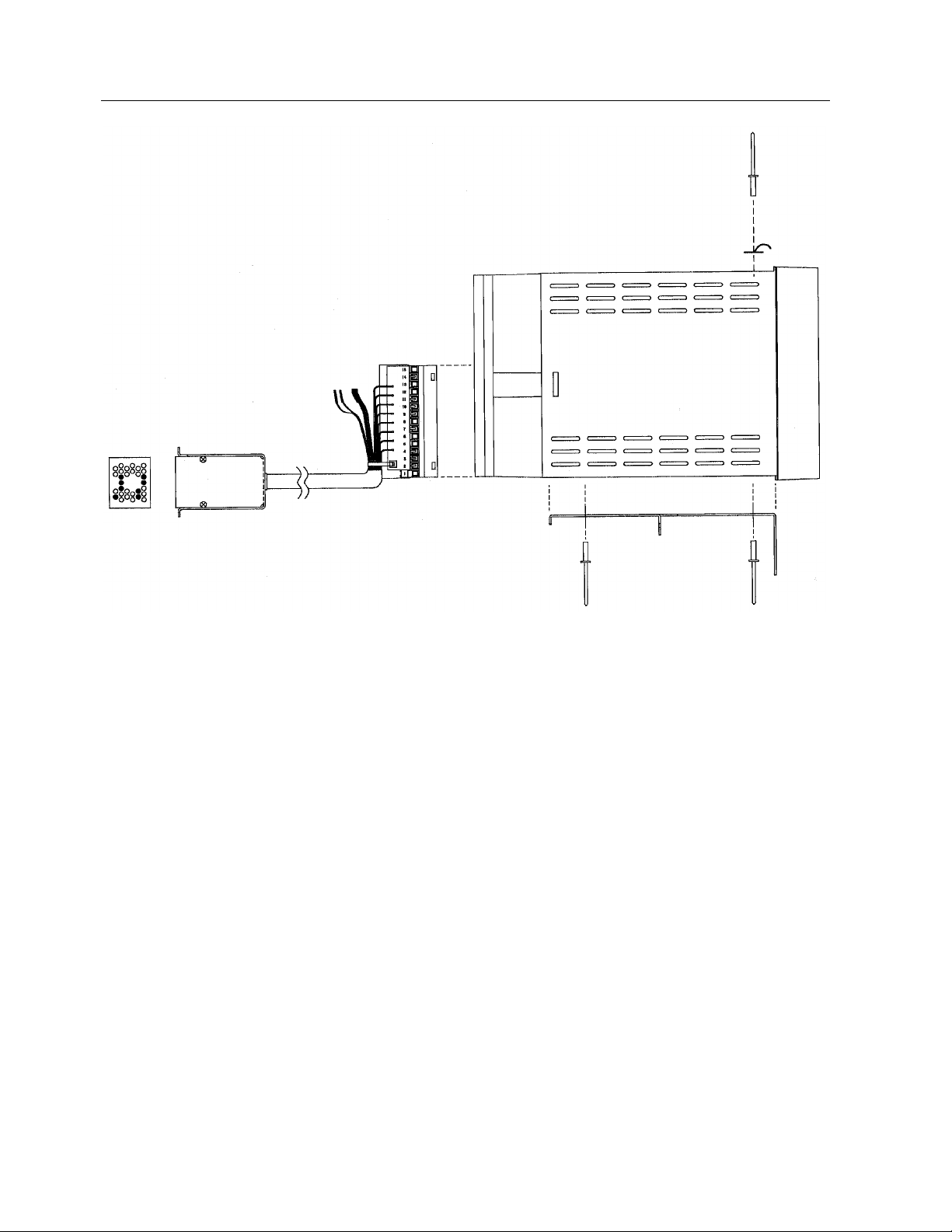
Figure 1. 2051R with Direct Connect Cable
SPEC 200 DIRECT CONNECT CABLE INSTALLATION
1. If field wiring is to be connected directly to the back of the MODCELL 2051 instrument,
proceed directly to Panel Installation. Terminate field connections describe in the I/O
instructions in IB-23C650-_._. If the intermediate installation is being employed, continue
with steps 2 through 9.
2. Remove the termination cover from the back of the MODCELL 2051.
3. Insert the termination end of the direct connect cable into the lower left termination block as
shown in Figure 2. With the cable facing down, the lowest pin of the terminator should be
inserted in terminal position NO. 2. Tighten all termination screws on the associated pins of
the terminator.
4. Dress the cable down and out the bottom of the termination assembly. Using the Tyrap
provided, secure the cable to the termination cover post as shown in Figure 2.
5. Replace the termination assembly cover and tighten in place.
6. Apply power to the MODCELL 2051R.
7. Enter the "Base Config **Menu**" (see IB-23C650-_._), select "volt" as the input type for the
process input.
2
Page 3

8. In the "Milliamp Input **Menu**", configure the analog input for an electrical input of 0 to 5
volts (the terminator has proportionately reduced the 0 to 10 Vdc signal to 0 to 5 Vdc). In the
"Milliamp Output **Menu**", configure the control output current to 0 to 40 milliamps. The
terminator has a precision resistor on the output to generate 0-10 Vdc with a 0 to 40 mA
output current.
9. Configure other options and features in the instrument as required for the application.
92902-93
2051F Conversion Instructions for Foxboro SPEC 200
TYRAP
Figure 2. 2051R Direct Connect Cable Wiring (Cover Removed)
PANEL INSTALLATION
The following steps describe intermediate installation replacement of the Foxboro SPEC 200 instrument
when using the direct connect cable.
2051R, Follow the panel instructions below for field terminations.
If making field connections directly at the back of the MODCELL
Caution!!
Be sure all power has been disconnected at the source
before attempting terminations.
1. Remove the SPEC 200 "controller" card from its position in the Foxboro Nest. Remove only
the card, not the Type 2AC module. The card is no longer required.
3
Page 4

92902-93
2051F Conversion Instructions for Foxboro SPEC 200
2. Remove the SPEC 200 instrument display from its shelf position. Disconnect the instrument cable
from the back of the display.
3. Connect the direct connect cable of the MODCELL 2051R into the SPEC 200 instrument cable.
Take care for correct orientation of pins.
4 Slide the MODCELL 2051R into the shelf position until the top bracket secures the instrument firmly
in place. If instrument power is not received through the instrument cable, connect power to the
MODCELL 2051R terminal block.
Panel Installation Procedure
1. The following steps describe intermediate installation replacement of the Foxboro SPEC 200
instrument when making connections directly at the back of the MODCELL 2051R instrument.
2. For quickest change-out, pre configure the MODCELL 2051R controller prior to panel installation.
3. Remove the SPEC 200 instrument display from its shelf position. Disconnect the instrument cable
from the back of the display. You may elect to remove the instrument cable all together or coil the
cable and leave in the back of the tray.
4. Make power and field connections per I/O instructions in IB-23C650-_._
5. Apply power and tune the instrument as required for the loop.
The Company’s policy is one of continuous product improvement and
the right is reserved to modify the information contained herein without
notice, or to make engineering refinements that may not be reflected in
this bulletin. Micromod Automation assumes no responsibility for errors
that may appear in this manual.
© 2004 MicroMod Automation, Inc. Printed in USA
8
92902-93, Issue 2 04/2005
MicroMod Automation, Inc.
75 Town Centre Drive
Rochester, NY USA 14623
Tel. 585-321 9200
Fax 585-321 9291
www.micromodautomation.com
 Loading...