

Page 1
MODBUS Communications for User’s Guide
MODCELL 2050R Supplement
Indicating Process Controller
2050R Model B Version 2.8
2051R Model B Version 2.8
Page 2
MicroMod Automation, Inc.
Further reference for more detailed
des, is copyrighted by
The Company
MicroMod Automation is dedicated to improving customer efficiency by providing the most cost-effective, applicationspecific process solutions available. We are a highly responsive, application-focused company with years of expertise in
control systems design and implementation.
We are committed to teamwork, high quality manufacturing, advanced technology and unrivaled service and support.
The quality, accuracy and performance of the Company's products result from over 100 years experience, combined with
a continuous program of innovative design and development to incorporate the latest technology.
Use of Instructions
Ì Warning. An instruction that draws attention to the
risk of injury or death.
q Caution. An instruction that draws attention to the risk
of the product, process or surroundings.
Although Warning hazards are related to personal injury, and Caution hazards are associated with equipment or property
damage, it
must be understood that operation of damaged equipment could, under certain operational conditions, result in degraded
process
system performance leading to personal injury or death. Therefore, comply fully with all Warning and Caution notices.
Information in this manual is intended only to assist our customers in the efficient operation of our equipment. Use of this
manual for
any other purpose is specifically prohibited and its contents are not to be reproduced in full or part without prior approval
of MicroMod Automation, Inc.
Licensing, Trademarks and Copyrights
MOD 30 and MOD 30ML are trademarks of MicroMod Automation, Inc.
MODBUS is a trademark of Modicon Inc.
Health and Safety
To ensure that our products are safe and without risk to health, the following points must be noted:
The relevant sections of these instructions must be read carefully before proceeding.
1. Warning Labels on containers and packages must be observed.
2. Installation, operation, maintenance and servicing must only be carried out by suitably trained personnel and in
accordance with the information given or injury or death could result.
3. Normal safety procedures must be taken to avoid the possibility of an accident occurring when operating in
conditions of high
4. pressure and/or temperature.
5. Chemicals must be stored away from heat, protected from temperature extremes and powders kept dry. Normal
safe handling procedures must be used.
6. When disposing of chemicals, ensure that no two chemicals are mixed.
Safety advice concerning the use of the equipment described in this manual may be obtained from the Company address
on the back
cover, together with servicing and spares information.
All software, including design, appearance, algorithms and source co
MicroMod Automation, inc. and is owned by MicroMod Automation or its suppliers.
Note. Clarification of an instruction or additional
information.
i Information.
information or technical details.
Page 3

IB-23C650M
CONTENTS
CONTENTS
Page
Introduction . . . . . . . . . . . . . . . . . . . . . . . . . . . . . . . . . 1
About This Supplement . . . . . . . . . . . . . . . . . . . . . . 1
About Modbus Communications . . . . . . . . . . . . . . . . 1
Installation . . . . . . . . . . . . . . . . . . . . . . . . . . . . . . . . . . 3
Controller Option Requirements . . . . . . . . . . . . . . . . 3
2-Wire Modbus Network Connections . . . . . . . . . . . . 3
4-Wire Modbus Network Connections . . . . . . . . . . . . 5
Communication Applications . . . . . . . . . . . . . . . . . . . . . . 9
Standard Control with Modbus Communications . . . . 9
Supervisory Control . . . . . . . . . . . . . . . . . . . . . . . . 9
Computer Control . . . . . . . . . . . . . . . . . . . . . . . . . . 10
RS-485 Communications Setup . . . . . . . . . . . . . . . . . . . 11
Basic Operation With a Host Device . . . . . . . . . . . . . . . . 27
Enabling Write Communication With a Host . . . . . . . 27
Standard Communication With a Host . . . . . . . . . . . . 27
Supervisory Station . . . . . . . . . . . . . . . . . . . . . . . . . 29
Computer Auto/Manual Station . . . . . . . . . . . . . . . . . 30
Diagnostic Messages . . . . . . . . . . . . . . . . . . . . . . . 31
Modbus Protocol . . . . . . . . . . . . . . . . . . . . . . . . . . . . . . 33
Communications Speed . . . . . . . . . . . . . . . . . . . . . . 33
Message Response Time . . . . . . . . . . . . . . . . . . . . 33
Messages Supported . . . . . . . . . . . . . . . . . . . . . . . 34
Message Formats . . . . . . . . . . . . . . . . . . . . . . . . . . 36
Controller Attribute Listing - Register Data . . . . . . . . . . . . 39
Common Data (registers) . . . . . . . . . . . . . . . . . . . . 39
Ramp/Soak Profile and Totalizer Data (registers) . . . . 42
Tuning Parameter Data (registers) . . . . . . . . . . . . . . 44
Alarm Data (registers) . . . . . . . . . . . . . . . . . . . . . . . 46
Computer Activity Data (registers) . . . . . . . . . . . . . . 47
Ramp/Soak Profile Configuration Data (registers) . . . . 49
More Computer Activity Data (registers) . . . . . . . . . . 51
Controller Attribute Listing - Coil Data . . . . . . . . . . . . . . . 55
Computer Activity Data (coils) . . . . . . . . . . . . . . . . . 55
Digital Input and Output Data (coils) . . . . . . . . . . . . . 56
Ramp/Soak Data (coils) . . . . . . . . . . . . . . . . . . . . . . 57
i
Page 4

IB-23C650M
CONTENTS
CONTENTS (Cont’d)
Page
Totalizer Data (coils) . . . . . . . . . . . . . . . . . . . . . . . . 57
Autotune Data (coils) . . . . . . . . . . . . . . . . . . . . . . . . 57
Process Alarm Data (coils) . . . . . . . . . . . . . . . . . . . . 58
Diagnostic Data (coils) . . . . . . . . . . . . . . . . . . . . . . . 59
Ramp/Soak Profile Data (coils) . . . . . . . . . . . . . . . . . 60
Record of Database . . . . . . . . . . . . . . . . . . . . . . . . . . . . 63
ILLUSTRATIONS
Figure Page
1 Typical 2-Wire Modbus Network Connections . . . . . . 4
2 Typical 4-Wire Modbus Network Connections with . . . 6
a Host Device as Master
3 Typical 4-Wire Modbus Network Connections with . . . 7
a MODCELL Multiloop Processor as Master
TABLES
Table Page
1 RS-485 Setup Menu . . . . . . . . . . . . . . . . . . . . . . . . 12
2 Modbus Messages Supported by MODCELL 2050 . . . 35
ii
Page 5

IB-23C650M
INTRODUCTION
INTRODUCTION
About This Supplement
This supplement provides instructions for installation, setup, and use of
the Modbus RS-485 serial communications option available in the
MODCELL 2050 Single Loop Controller. Comprehensive instructions
covering all aspects of the controller not related to Modbus
communication are included in the
IB-23C650 User’s Guide.
Specific information provided in this supplement is as follows:
• Instructions for connecting the controller to a Modbus network using
either a 2-Wire or 4-wire configuration.
• Application information including controller operation as a supervisory
station or computer auto/manual station using Modbus
communications.
• Step-by-step instructions for setup of the communications function
using the RS-485 MENU in the controller data base.
• Operating instructions for the controller when Modbus
communication with a host device is enabled.
• A description of the Modbus messages supported and the message
formats.
• Controller attribute reference data. The listing includes register data
for numeric attributes and coil data for boolean (discrete) attributes.
About Modbus Communications
A 2050R controller and a host device connected to a Modbus network
communicate via a master/slave relationship. The host device functions
as the Modbus master and the controller functions as the slave. The
master is in command of the communications transaction and talks to
one slave (controller) at a time. The master sends a message to a
slave and waits to receive an answer back from that slave before it
talks to the another slave. Each slave has a unique address which
1
Page 6

IB-23C650M
INTRODUCTION
allows it to be identified by the master. This permits multiple slaves
(controllers) to reside on a single Modbus network.
The controller can be assigned any address between 1 and 247.
Addresses are set in the RS-485 MENU as part of the setup for
modbus communication. Address 0 is the “broadcast” address. Only
write messages can use it. All controllers process the message, but
there is no response back to the host.
Other types of slaves may reside on a network with the controllers.
Modbus does not support peer-to-peer communications where two
controllers can talk directly with each other.
2
Page 7

IB-23C650M
INSTALLATION
INSTALLATION
This section provides instructions for making Modbus network connections
using either a 2-wire or 4-wire configuration. This information assumes that
physical installation and all other electrical connections are being made in
accordance with the instructions in IB-23C650.
Before making any connections, be sure the controller can support Modbus
communications; see the option requirements below.
Controller Option Requirements
The controller must be equipped with an option card and firmware Version 2 to
run MODBUS RS-485 serial communications. The option card (Catalog No.
2050NZ10100A) and Version 2 firmware may have already been installed in
the controller during manufacture. If necessary these items can be installed in
the field. Instruments manufactured with the option card and Version 2
firmware are identified by digits in the instrument catalog number as shown
below:
Sample Catalog Number: 2050RZ10 1 02 A
RS-485 Communications Option Card
RS-485 Firmware Version
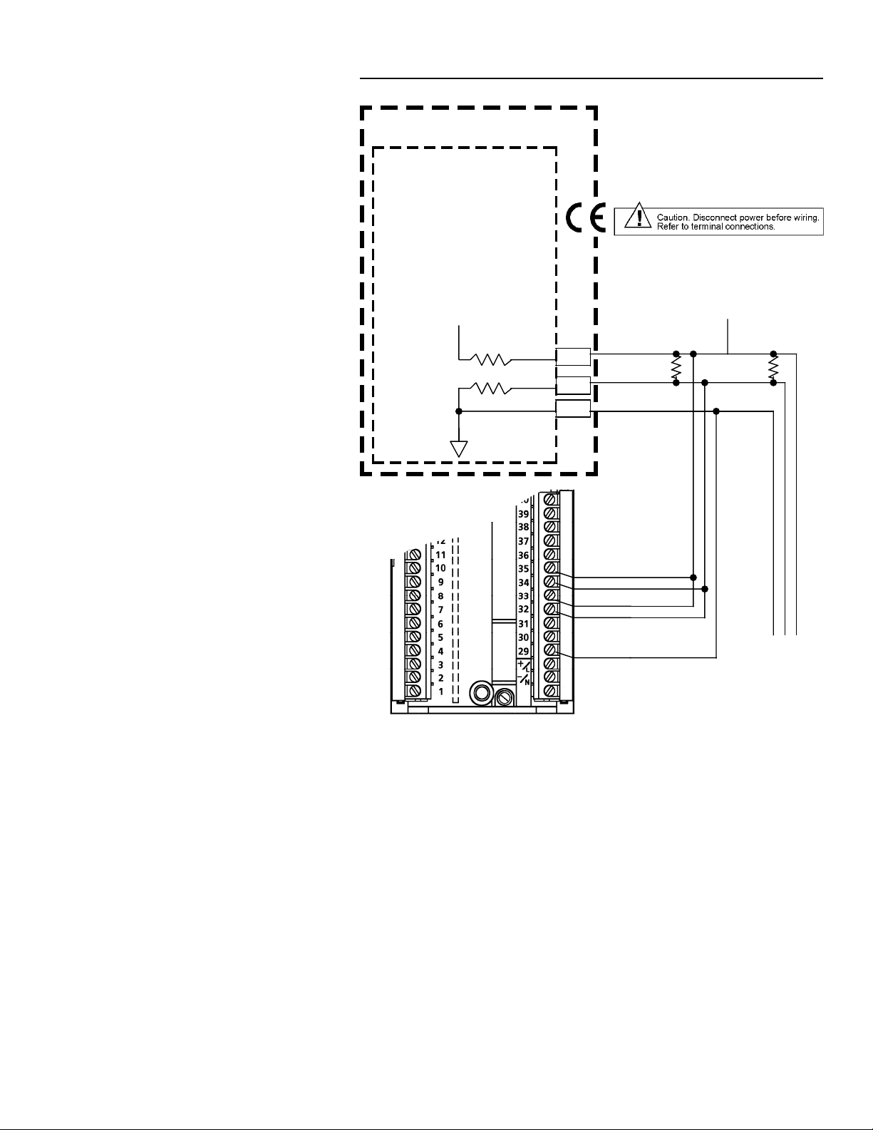
2-Wire Modbus Network Connections
Connections for a typical Modbus network using a 2-wire configuration are
shown in Figure 1. The host device functions as the master and the
controllers function as slaves. It is recommended that no more than 32 devices
be connected on a single network. The devices and host must have a
common ground.
The master is responsible for providing the 560 ohm pull-up and pull-down
bus stabilizing resistors. Connect 120 ohm termination resistors across the
transmission line at both ends as shown. The number of devices can be
increased by the use of repeaters. The termination resistors may not be
required if the line length is very short.
Cable requirements depend on the length of the run. For short runs of 10 to
25 ft (3 to 6m) virtually any 2-wire shielded or twisted pair is suitable. For runs
up to 4000 ft (1219m) Belden 9841 cable or equivalent is recommended. This
cable is a 24 AWG twisted pair with a foil shield. The insulation is low
dissipation (polypropylene). A drain wire is provided for grounding the shield.
3
Page 8
IB-23C650M
INSTALLATION
Personal Computer Modbus Master
RS485 Interface
+5V dc
560
All resistors are 0.25W.
Other 2050R's
wired same way
without resistors.
RX/TX+
120
RX/TX-560
COM
120
RX+
RX -
TX+
TX -
COM
Last
2050R
Figure 1. Typical 2-Wire Modbus Network Connections
.
4
Page 9

IB-23C650M
INSTALLATION
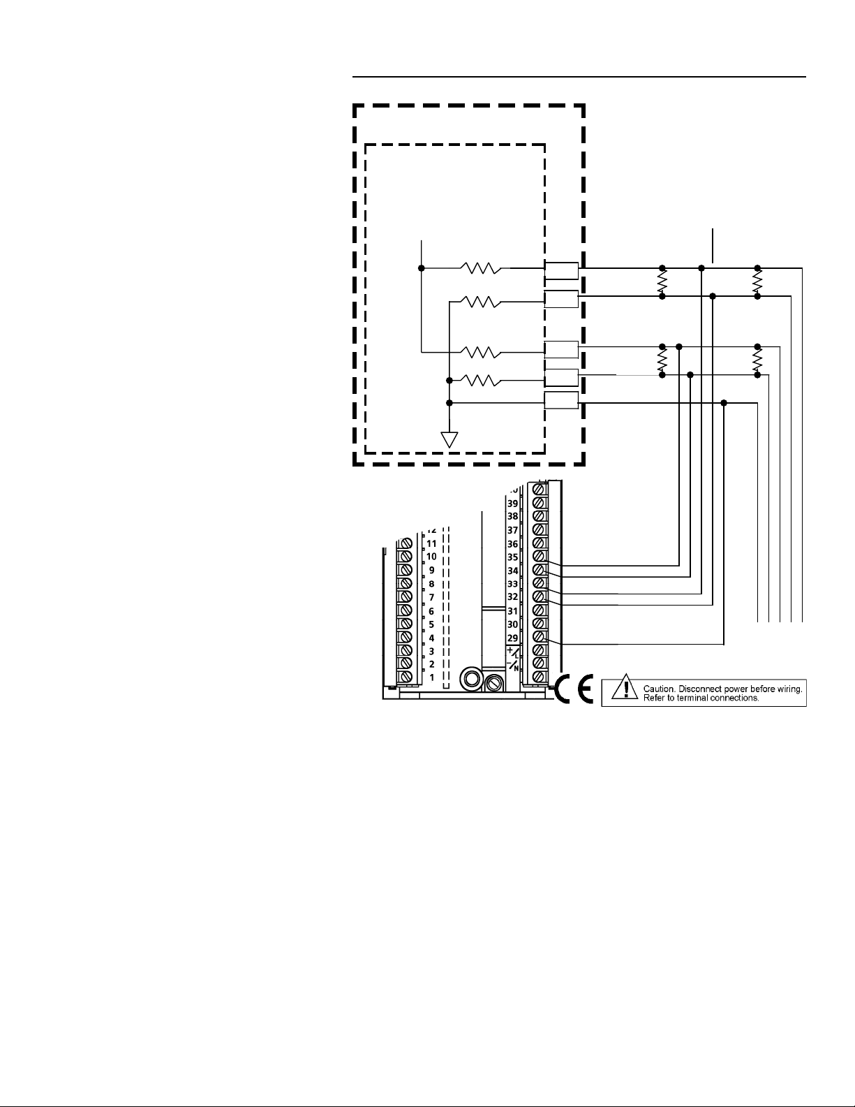
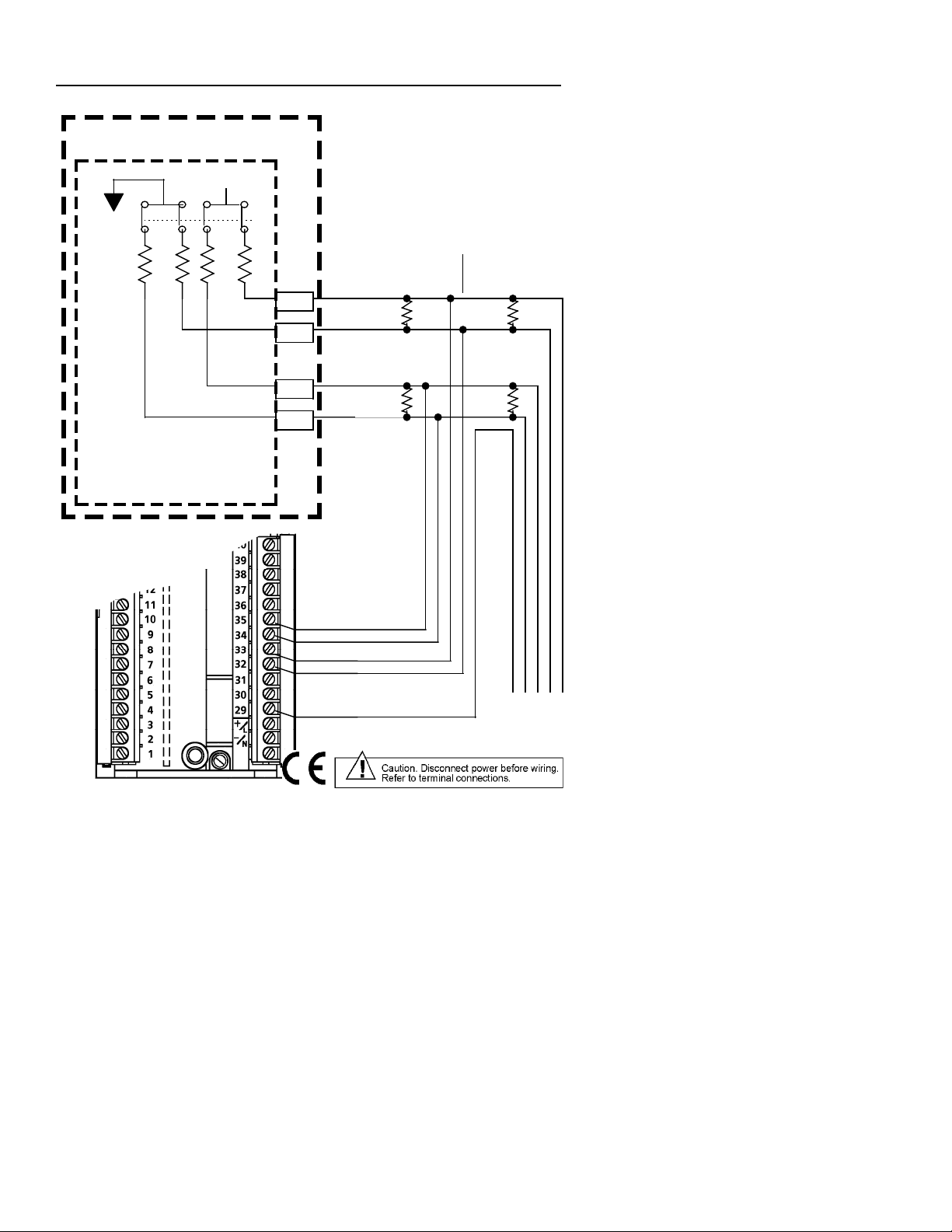
4-Wire Modbus Network Connections
Connections for typical Modbus networks using a 4-wire configuration are
shown in Figures 2 and 3. The host device functions as the master and the
controllers function as slaves. It is recommended that no more than 32 devices
be connected on a single network. The number of devices can be increased
by the use of repeaters.
When the host is a device such as a personal computer, the instruments and
host must have a common ground as shown in Figure 2. When the host is a
MODCELL Multiloop Processor, Figure 3, connection of the processor to the
instrument common line is not required because the processor connections
are optically isolated.
The master is responsible for providing the 560 ohm pull-up and pull-down
bus stabilizing resistors. In the MODCELL processor, these resistors are
provided in the RS-485 communications module, and the TERM switch on the
module must be set at YES to connect the resistors to the network (see
IB-23C600 MODCELL Multiloop Processor Installation Instructions for
more information). Connect 120 ohm termination resistors across the
transmission line at both ends as shown. The termination resistors may not be
required if the line length is very short.
Cable requirements depend on the length of the run. For short runs of 10 to
25 ft (3 to 6m) virtually any 2-wire shielded or twisted pair is suitable. For runs
up to 1000 ft (305m), Belden 9502 cable or equivalent is recommended. This
cable is a dual 24 AWG twisted pair with an overall foil shield. A drain wire is
provided for grounding the shield. For runs up to 4000 ft (1219m) Belden
9729 or equivalent is recommended. This cable is a dual 24 AWG twisted pair
with a foil shield for each pair. The cable insulation is low dissipation
(polypropylene). Two separate drain wires are provided for grounding the
shields.
5
Page 10
IB-23C650M
INSTALLATION
Personal Computer Modbus Master
RS485 Interface
+5V dc
560
560
560
560
2050R Controller
(Modbus Slave)
All resistors are 0.25W.
Other 2050R's
wired same way
without resistors.
RX+
120
RX-
TX+
120
TX-
COM
120
120
RX+
RX -
TX+
TX -
COM
Figure 2. Typical 4-Wire Modbus Network Connections with a Host
Device as Master
6
Last
2050R
Page 11
IB-23C650M
INSTALLATION
Modcell Processor
Isolated +5Vdc
560
TERM
Switch
YES
Modbus Master
2034N RS-485 MODULE
(Module Locations 31 & 32)
2050R Controller
(Modbus Slave)
S31
1
2
S32
1
2
All resistors are 0.25W.
Other 2050R's
wired same way
without resistors.
RX+
120
RX-
TX+
120
TX-
120
120
RX+
RX -
TX+
TX -
COM
2050R
Figure 3. Typical 4-Wire Modbus Network Connections with a
MODCELL Multiloop Processor as Master
Last
7
Page 12

IB-23C650M
INSTALLATION
Blank Page
8
Page 13

IB-23C650M
COMMUNICATION APPLICATIONS
COMMUNICATION APPLICATIONS
The following are sample applications available with the controller through the
use of Modbus communications. The RS-485 MENU is used to set up the
controller for these applications. The setup requirements are described in
detail in Table 1.
Standard Control With Modbus Communications
For this application, the instrument acts as a stand alone single loop controller
which can receive read/write commands from a host Modbus device such as a
personal computer, MODCELL Multiloop Processor, PLC, etc. Multiple
instruments and other devices can be on a single Modbus network. Each
device on a network must have a unique address. The instrument address is
assigned using the Bus Address attribute in the RS-485 MENU.
During runtime operation, the last attribute entry to the controller becomes the
active entry. For example, if the operator sets an active set-point value via the
instrument display and moments later the host sends a new active set-point
value, the controller uses the operators value until it receives the host value.
At that time the host value becomes the new active set-point value.
A prompt in the DISPLAYS MENU permits the operator to disable the host
from writing to the controller. The host can still receive data from the
instrument, but can not write to it. This is useful if the operator must maintain
manual control of the process and does not want the host to write to the
instrument. The operator can reinitiate the host write capacity via the
DISPLAYS MENU when required.
The Computer Timeout attribute is not active in this application. When
necessary, this attribute is initialized by the host as a means of notifying the
instrument of a communication failure. In this application, failure of the host or
the communications has no effect on instrument operation. The controller
continues to operate with its current attribute values as if nothing happened.
Supervisory Control
The controller receives its set-point from the host device in a supervisory
control application. All other aspects of controller operation are similar to
standard control as described above. The PID control function is provided by
the controller.
9
Page 14

IB-23C650M
COMMUNICATION APPPLICATIONS
Attributes in the RS-485 MENU permit the supervisory control mode to be
indicated via the set-point status display on the front of the instrument. Each
of the three characters in the status display is configurable so that the user
can choose an appropriate mnemonic to represent the supervisory control
mode.
A timeout value can be defined for communications traffic to the instrument via
the Computer Timeout attribute. An activity timer in the instrument is
initialized by the host when operation starts. This action also enables the
configured set-point status display.
The timer monitors the communications bus for activity to the instrument
within the specified timeout period. If there is no communications activity to
the instrument during the specified time, a "computer failure" is declared.
During a computer failure the controller assumes local control with I/O and
mode states as defined under "Computer Failure Setup" in the RS-485
MENU.
When the controller is receiving a set-point from the host, the set-point status
display can be configured to indicate that the host is the set-point source. The
R/L key still performs its normal function. The set-point status display
indicates changes in the set-point source ( LOC, LO1, etc. ).
Computer Control
In a computer control application, the instrument functions as a computer
auto/manual station. The host performs the PID control function with the
results communicated to the controller and then to the field.
Attributes in the RS-485 MENU permit the computer control mode to be
indicated via the control and set-point status displays on the front of the
instrument. Each of the three characters in each status display is configurable
so that the user can choose appropriate mnemonics to represent the computer
control mode and set-point status.
A computer timeout value is defined and a timer monitors communications in
the same manner as for supervisory control. When the computer is active, the
function of the AUTO, R/L and Maunal keys can be configured to provide a
signal to the computer upon which it can take some programmed action.
10
Page 15

IB-23C650M
RS-485 COMMUNICATIONS SETUP
RS-485 COMMUNICATIONS SETUP
Before starting the communications setup, refer to the Setup Section in
IB-23C650 for information about the setup preparation, method, and controls.
Perform the communications setup using the RS-485 MENU as described in
Table 1.
Note: In order to access the RS-485 MENU, the RS-485 Communications
Enable attribute in the BASE CONFIGURATION MENU must be set at
YES. Refer to Table 1, Base Configuration in IB-23C650.
11
Page 16

IB-23C650M
RS-485 COMMUNICATIONS SETUP
Table 1. RS-485 Setup Menu
Step Step Description
1
2
3
4
5
RS-485 Menu. (requires option board)
UP
moves to RELAYS **MENU**.
DN
moves to RAT BIAS **MENU** if A/M ratio bias
is enabled, or to SETPTS **MENU** otherwise.
SCRL
advances to Step 2 (read only in auto).
Bus Enable
UP
or
DN
selects ON or OFF.
SCRL
to advance to Step 3.
Instrument Address
UP
or
DN
sets instrument address.
SCRL
to advance to Step 4.
Baud Rate
UP
or
DN
sets instrument baud rate.
SCRL
to advance to Step 5.
Parity Selection
UP
or
DN
sets instrument parity.
SCRL
to advance to Step 6.
Top
Display
RS-485
BUS
BUS
BAUD
PARITY
6
7
12
Stop Bit Selection
UP
or
DN
sets number of stop bits.
SCRL
to advance to Step 7.
Allowed Access Type
UP
or
DN
sets communications access type.
SCRL
to advance to Step 8.
STOP
ACCESS
Page 17

RS-485 COMMUNICATIONS SETUP
Table 1. RS-485 Setup Menu
IB-23C650M
Middle
Display
**MENU**
ENABLE ON
Bottom
Display
Entry Description
None.
= enables the bus for communications with a
host device.
= disables the communications bus from
OFF
receiving or writing with a host device.
The bus must be disabled in order to make
changes in the following steps.
ADDRESS XXX Where X is any address between 1 and 247.
Each instrument on a bus must have a unique
address.
RATE XXXX Where X is one of the following baud rates;
150, 300, 1200, 2400, 4800, 9600, 19200,
38400. All devices on the same bus must have
the same baud rate.
SELECT
ODD
EVEN
BITS 1
= Parity calculation is odd.
= Parity calculation is even.
Note: Total word length equals start bit (1) +
data (8 bits) + parity (1) + stop bits (1/2).
Total word length can be 11 or 12 bits.
= One stop bit appended to character.
2
= Two stop bits appended to character.
TYPE RD_ONLY
RD/WRITE
= Allows the host device to read only from the
controller.
= Allows the host device to read data from and
write data to the controller.
13
Page 18

IB-23C650M
RS-485 COMMUNICATIONS SETUP
Table 1. RS-485 Setup Menu
Step Step Description
8
8.1
8.2
Computer Activity Setup.
UP
begins setup at Step 8.1.
SCRL
to advance to Step 9 (Enable Bus).
Computer Activity Timeout.
UP
or
DN
sets value.
SCRL
to advance to Step 8.2.
Computer Activity Mnemonic (Auto )
UP
or
DN
sets value (press
press
UP
to start at A or press
Press
SCRL
to access the next character.
Repeat through the third character. Press
after the third character to continue with step 8.3.
UP
to begin then
DN
to start at 9 ).
Top
Display
COMPUTER
COMPUTER
CMP AUTO
SCRL
8.3
14
Computer Activity Mnemonic (Manual)
UP
or
DN
set values and
characters as described in Step 8.2. Press
after the third character to continue with step 8.4.
SCRL
accesses
SCRL
CMP MAN
Page 19

RS-485 COMMUNICATIONS SETUP
Table 1. RS-485 Setup Menu
IB-23C650M
Middle
Display
SETUP
Bottom
Display
Entry Description
Steps 8.1 through 8.12.6.1.1allow setup for the
controller to be used as a computer
auto/manual (CAM) or supervisory station when
connected to a host device. No entries are
required if the instrument is to be used as a
stand alone controller which can receive
read/write commands from a host device.
TIMEOUT XXXXX X represents a time between 1 and 16383
seconds. The computer activity timeout
function is initialized and maintained by the
computer (host). If the time between sessions
of bus activity is greater than this value, a
Computer Fail is declared. This causes the
activity timer to be disabled, and the computer
status reverts to LOCKED. The controller
returns to local with parameters as defined in
Step 8.12.
MNEMONIC XXX Where X = any of the following characters:
Letters A through Z,
Any of the special characters:
b, c, super c, d, h, sub L, super L,
super m, super n, o, r, super T, u,
super V, w, <, >, =, +, –, *, #, /, %,
degrees (super o), or space,
Numbers 0 through 9.
Mnemonic appears in the control mode status
display when the activity timer is initialized by
the host and control mode is automatic.
Default mnemonic is CMP.
MNEMONIC XXX Where X = any of the characters listed in
Step 8.2
Mnemonic appears in the control mode status
display when the activity timer is initialized by
the host and control mode is manual.
Default mnemonic is MAN.
15
Page 20

IB-23C650M
RS-485 COMMUNICATIONS SETUP
Table 1. RS-485 Setup Menu
Step Step Description
8.4.
8.5
8.6
Computer Control Mode Value
UP
or
DN
sets value.
SCRL
to advance to Step 8.5
Computer Set-point Mnemonic (Local)
UP
or
DN
sets value (press
press
UP
to start at A or press
Press
SCRL
to access the next character.
Repeat through the third character. Press
after the third character to continue with Step 8.6.
Computer Set-point Mnemonic (Local 2)
UP
or
DN
set values and
characters as described in Step 8.5. Press
after the third character to continue with Step 8.7.
UP
SCRL
to begin then
DN
to start at 9.
accesses
Top
Display
COMPUTER
CMP LOC
SCRL
CMP LO2
SCRL
8.7
16
Computer Set-point Mnemonic (Local 3)
UP
or
DN
set values and
characters as described in Step 8.5. Press
after the third character to continue with Step 8.8.
SCRL
accesses
SCRL
CMP LO3
Page 21

RS-485 COMMUNICATIONS SETUP
Table 1. RS-485 Setup Menu
IB-23C650M
Middle
Display
MODE VAL XXX
Bottom
Display
Entry Description
Where X = any value between 0 and 255.
This value is OR'd into bits 9-12 of the Control
Mode register (#14) when the activity timer is
enabled. Default value is 1.
MNEMONIC XXX Where X = any of the following characters:
Letters A through Z,
Any of the special characters:
b, c, super c, d, h, sub L, super L,
super m, super n, o, r, super T, u,
super V, w, <, >, =, +, –, *, #, /, %,
degrees (super o), or space,
Numbers 0 through
Mnemonic appears in the set-point status
display when the activity timer is initialized by
the host and set-point source is local, or when
coil #8 is True and the computer set-point
mode is Local. Default is LOC.
MNEMONIC XXX Where X = any of the characters listed in
Step 8.5.
Mnemonic appears in the set-point status
display when the activity timer is initialized by
the host and set-point source is Local 2.
Default is LO2.
MNEMONIC XXX Where X = any of the characters listed in
Step 8.5.
Mnemonic appears in the set-point status
display when the activity timer is initialized by
the host and set-point source is Local 3.
Default is LO3.
17
Page 22

IB-23C650M
RS-485 COMMUNICATIONS SETUP
Table 1. RS-485 Setup Menu
Step Step Description
8.8
8.9
8.10
8.11
Computer Set-point Mnemonic (Local 4)
UP
or
DN
set values and
characters as described in Step 8.5. Press
after the third character to continue with Step 8.9.
Computer Set-point Mnemonic (Remote)
UP
or
DN
set values and
characters as described in Step 8.5. Press
after the third character to continue with Step 8.10.
Computer Set-point Mode Value.
UP
or
DN
sets value
SCRL
to advance to Step 8.11
Use Computer Active Tag
UP
or
DN
selects yes or no.
SCRL
to advance to Step 8.11.1 from yes or
Step 8.12 (Computer Failure Setup) from no.
SCRL
SCRL
Top
Display
CMP LO4
accesses
SCRL
CMP REM
accesses
SCRL
COMPUTER
USE CMP
8.11.1
8.12
18
Computer Active Tag
UP
or
DN
sets value (press
press
UP
to start at letter A or press
9.
Press
SCRL
to access the next character.
Repeat through the last character. Press
after the last character to advance to Step 8.12
Computer Failure Setup.
UP
begins setup at step 8.12.1.
SCRL
to advance to Step 9 (bus enable).
UP
to begin then
DN
to start at
SCRL
COMPUTER
CMP FAIL
Page 23

RS-485 COMMUNICATIONS SETUP
Table 1. RS-485 Setup Menu
IB-23C650M
Middle
Display
MNEMONIC XXX
Bottom
Display
Entry Description
Where X = any of the characters listed in
Step 8.5.
Mnemonic appears in the set-point status
display when the activity timer is initialized by
the host and set-point source is Local 4.
Default is LO4.
MNEMONIC XXX Where X = any of the characters listed in
Step 8.5.
Mnemonic appears in the set-point status
display when the activity timer is initialized by
the host and set-point source is remote.
Default is REM.
SPMD VAL XXX Where X = any value between 5 and 255.
This value is OR'd into bits 13-6 of the the setpoint mode register (#15) when the activity
timer is enabled. Default value is 1.
ACT TAG YES
= Display the computer active tag configured
in Step 8.11.1 instead of the Tag Name
configured in the Tune Menu when the activity
timer is initialized by the host, This display
appears in the top location in the Displays
Menu.
=Don’t display computer active tag.
NO
ACT TAG XXXXXXXX Where X = any of the characters listed in
Step 8.5.
This is the tag name displayed when Step 8.11
is set at yes. Default tag is COMPUTER.
SETUP This menu provides setup for the control mode,
output values, set-point value and relays status
following a computer failure. A failure is
defined as a loss of communications from teh
computer for a time greater than the timeout
period configured in step 8.1.
19
Page 24

IB-23C650M
RS-485 COMMUNICATIONS SETUP
Table 1. RS-485 Setup Menu
Step Step Description
8.12.1
8.12.1.1 Computer Fail Output.
8.12.1.1.1 Computer Fail Output Value.
8.12.2
Computer Fail Control Mode.
UP
or
DN
sets desired mode.
SCRL
to advance to
Step 8.12.2 from AUTO if output 2 is available
Step 8.12.3 from AUTO if Relay A is available
Step 8.12.4 from AUTO if Relay B is available
Step 8.12.5 from AUTO if Relay C is available
or to Step 8.12.1.1 otherwise.
UP
or
DN
sets control output value.
SCRL
to advance to Step 8.12.1.1.1 (Computer
Failed Output Value) from "NEW VALU" or to any
step between 8.12.2 and 8.12.5 for outputs
enabled as manual or computer only. If no
outputs are assigned to manual or computer only,
continue with Step 8.12.6 (Computer Fail Set-point
Mode).
UP
or
DN
sets output value.
SCRL
to advance to any step between 8.12.2 and
8.12.5 for outputs enabled as manual or computer
only. If no outputs are assigned to manual or
computer only, continue with Step 8.12.6
(Computer Fail Set-point Mode).
Computer Fail Output 2.
UP
or
DN
sets value
SCRL
to advance to Step 8.12.2.1 (Computer Fail
Output 2 Value) from "NEW VALU" or to any step
between 8.12.3 and 8.12.5 for outputs enabled as
manual or computer only. If no additional outputs
are assigned to manual or computer only, continue
with Step 8.12.6 (Computer Fail Set-point Mode).
Top
Display
CMP FAIL
CMP FAIL
CMP FAIL
CMP FAIL
20
Page 25

RS-485 COMMUNICATIONS SETUP
Table 1. RS-485 Setup Menu
IB-23C650M
Middle
Display
CTL MODE LAST
OUTPUT LAST
Bottom
Display
MANUAL
AUTO
NEW VALU
Entry Description
=controller maintains the same control mode
after a communications failure has been
detected.
=controller operates in manual following a
computer failure with the output as defined in
Step 8.12.1.1.
=controller operates in automatic following a
computer failure with the set-point as defined in
Step 8.12.6.1.1.
=control output holds at the output value prior
to the computer failure.
=control output set to value set in Step
8.12.1.1.1.
Note: This new value is used only if the
controller mode in Step 8.12.1 is manual (MAN)
and a computer failure is detected.
OUT VAL XXX Where X = any value between 0 and 100%.
This is the output of the controller if a computer
failure is detected and the controller is in
manual.
OUTPUT 2 LAST
NEW VALU
=output 2 holds at the same value prior to the
computer failure.
=output set to value set in Step 8.12.2.1.
Note: This new value is used only if the
retransmission variable in the "MA OUTP
MENU" has been selected as manual or
computer only, and if a computer failure is
detected (see Table 4 in IB-23C650 for more
information).
21
Page 26

IB-23C650M
RS-485 COMMUNICATIONS SETUP
Table 1. RS-485 Setup Menu
Step Step Description
8.12.2.1 Computer Fail Output 2 Value.
UP
or
DN
sets output 2 value.
SCRL
to advance to any step between 8.12.3 and
8.12.5 for additional outputs enabled as manual or
computer only. If no outputs are assigned to
manual or computer only, continue with Step
8.12.6 (Computer Fail Set-point Mode).
8.12.3
8.12.4
8.12.5
8.12.6
Computer Fail Relay A.
UP
or
DN
sets relay condition.
SCRL
to advance to Step 8.12.4 for relay B or
Step 8.12.5 for relay C if they have been selected
for manual or computer only or to Step 8.12.6
(Computer Fail Set-point Mode) if relays B or C
have not been selected.
Computer Fail Relay B.
UP
or
DN
sets relay condition.
SCRL
to advance to step 8.12.5 for relay C if it
has been selected for manual or computer only or
to Step 8.12.6 (Computer Fail Set-point Mode) if it
has not been selected.
Computer Fail Relay C.
UP
or
DN
sets relay condition.
SCRL
to advance to Step 8.12.6 (Computer Fail
Set-point Mode).
Computer Fail Set-point Mode.
UP
or
DN
sets the set-point mode.
SCRL
to advance to Step 9 (Bus Enable) from
LAST, REMOTE, or a local set-point configured as
fixed in the set-points menu, or to Step 8.12.6.1
(Computer Fail Set-point) otherwise.
Top
Display
CMP FAIL
CMP FAIL
CMP FAIL
CMP FAIL
CMP FAIL
22
Page 27

RS-485 COMMUNICATIONS SETUP
Table 1. RS-485 Setup Menu
IB-23C650M
Middle
Display
Bottom
Display
OUT2 VAL XXX
RELAY A LAST
OFF
ON
RELAY B LAST
OFF
ON
RELAY C LAST
OFF
ON
SPT MODE LAST
LOCAL
LOCAL-2
LOCAL-3
LOCAL-4
REMOTE
Entry Description
Where X = any value between 0 and 100%.
This is the output 2 value the controller will
have if the retransmission variable in the "MA
OUTP MENU" has been selected as manual or
computer only and a computer failure has been
detected.
=relay state remains as it was prior to the
detection of a computer fail.
=relay goes to off state after a computer fail.
=relay goes to on state after a computer fail.
=relay state remains as it was prior to the
detection of a computer fail.
=relay goes to off state after a computer fail.
=relay goes to on state after a computer fail.
=relay state remains as it was prior to the
detection of a computer fail.
=relay goes to off state after a computer fail.
=relay goes to on state after a computer fail.
= controller uses the same set-point source
after a computer fail has been detected.
=Selecting any other set-point source causes
the controller to use the selected set-point after
a computer fail has been detected.
Note: The local set-points need not be enabled
in the "SETPTS MENU" for this use. If
ramp/soak is running at the time of a computer
fail, and a mode other than LAST has been
selected, ramp/soak will discontinue.
23
Page 28

IB-23C650M
RS-485 COMMUNICATIONS SETUP
Table 1. RS-485 Setup Menu
Step Step Description
8.12.6.1 Computer Fail Set-point
UP
or
DN
sets the set-point value.
SCRL
to advance to step 9 (Bus Enable) from
LAST or Step 8.12.6.1.1 (Computer Fail Set-point
Value) from NEW VALU.
8.12.6.1.1 Computer Fail Set-point Value.
UP
or
DN
sets the set-point value.
SCRL
to advance to Step 9 (Bus Enable)
9
Bus Enable.
UP
or
DN
SCRL
to advance to Step 1
selects ON or OFF.
Top
Display
CMP FAIL
CMP FAIL
BUS
24
Page 29

RS-485 COMMUNICATIONS SETUP
Table 1. RS-485 Setup Menu
IB-23C650M
Middle
Display
SETPOINT LAST
Bottom
Display
NEW VALU
Entry Description
If any of the LOCAL set-point sources were
selected in the previous step, "LAST" will
cause the controller to use the current set-point
value in that location. Selecting "NEW VALU"
allows a new value (defined in Step 8.12.6.1.1)
to be written into the set-point source register.
Note: The set-point value entered into that setpoint source in the "SETPTS MENU" will be
overwritten by the new value.
Ex.; LOC3 is selected as the computer fail setpoint mode (step 8.4.6) and has been set at
58.3 in the "SETPTS MENU". The computer
fail set-point value (set in Step 8.12.6.1.1) is set
at 38.6. When a computer fail is detected, 38.6
will be written into LOC3.
SPT VALU XXXX Where X = -3000 to 30000. This value is
limited by the specific set-point limits.
ENABLE ON
= enables the bus for communications with a
host device.
= disables the communications bus from
OFF
receiving or writing with a host device.
This duplicate entry is provided for
convenience since the bus must be re-enabled
following any parameter change.
NOTE: IF this attribute setting is changed
from OFF to ON, communication with
the host device must be initiated by
switching from LOCKED to
REQUESTED at the computer (CMP)
prompt in the DISPLAYS MENU. See
Basic Operation With a Host
Device for more information.
25
Page 30

IB-23C650M
RS-485 COMMUNICATIONS SETUP
Blank Page
26
Page 31

IB-23C650M
BASIC OPERATION WITH A HOST DEVICE
BASIC OPERATION WITH A HOST DEVICE
This section supplements the Basic Operation Section in IB-23C650.
It covers the operational activities related to Modbus communication
which are performed in the DISPLAYS MENU.
Enabling Write Communication With a Host
After completing the RS-485 communications setup, the host can read
instrument data when the bus is enabled (see Table 1, Step 9). If write
communication is required and the communication mode is LOCKED,
the write function can be enabled as follows:
1. Go to the DISPLAYS MENU.
2. Press scroll. This allows the
computer activity status to be
displayed in the DISPLAYS
MENU.
3 Press scroll until CMP appears
in the bottom status display
location.
4. Press
Standard Communication With a Host
In the standard communications mode the instrument functions as a
stand alone controller which can receive read and write commands from
the host. In this mode the last attribute entry becomes the active entry.
For example, if the operator sets an active set-point value via the
instrument display, and moments later the host sends a new set-point
value, the controller uses the operators value until it receives the host
value. At that time the host value becomes the new active set-point.
DN
or UP key to initiate
communication with the host.
When the key is pressed, the
engineering display reads
REQUESTD for a few seconds,
then changes to ENABLED.
27
Page 32

IB-23C650M
BASIC OPERATION WITH A HOST DEVICE
If necessary, the operator can disable the host from writing to the
controller. This gives the operator total control of the instrument
operation. The host can still read data from the instrument but cannot
write to it.
To disable the host, access the CMP status display as described in the
previous section. When CMP appears, press the
change the status from ENABLED to LOCKED.
DN
or UP key to
28
Page 33

IB-23C650M
BASIC OPERATION WITH A HOST DEVICE
Supervisory Station
When the controller and host device are configured to provide a
supervisory function, the controller receives its set-point from the host
device. The controller executes its PID algorithm in the normal manner,
and in general functions the same as a standard controller. This activity
is initiated by the host.
The displays and control key operation for a supervisory station are as
follows:
Tag display can be configured to
indicate that the host has initiated
activity. Default indication is
COMPUTER.
The auto and manual keys perform
their normal function.
This status display shows a
configured mnemonic when the
host initializes activity. The default
is CMP. For supervisory operation,
the display can be configured to
show AUT to indicate that the PID
function still resides in the
controller.
The R/L key can be disconnected
by a coil when the host initializes
activity. This allows the key to be
read by the host to select multiple
set-points stored in the host.
The status display shows a
configurable mnemonic indicating
which host set-point is being
written to the controller. Defaults
are: LOC, LO2, LO3, LO4 and
REM.
To check the Modbus
communication status, press the
scroll key to access CMP. Status
is indicated as ENABLED or
LOCKED.
29
Page 34

IB-23C650M
BASIC OPERATION WITH A HOST DEVICE
Computer Auto/Manual Station
When the controller and host device are configured to provide a
computer auto/manual function, the host performs the PID control
function. The results are communicated to the instrument and then to
the field. This activity is initiated by the host.
The displays and control key operation for a computer auto/manual
station are as follows:
Tag display can be configured to
indicate that the host has initiated
activity. Default indication is
COMPUTER.
The auto and manual keys can be
disconnected by a coil when the
host initiates activity. This allows
the keys to be read by the host
which then initiates programmed
action.
This status display shows a
configured mnemonic indicating the
programmed action. Defaults are
CMP for automatic and MAN for
manual.
30
The R/L key permits selection of
any set-point enabled in the setpoints menu. This may be
disconnected by a coil so the R/L
key can be read by the host to
select set-points stored in the host.
The status display shows a
configurable mnemonic indicating
the set-point source. Defaults are:
LOC, LO2, LO3, LO4 and REM.
To check Modbus communication
status, press the scroll key to
access CMP. Status is indicated
as ENABLED or LOCKED. The
locked status is displayed after the
controller is switched to manual.
Page 35

IB-23C650M
BASIC OPERATION WITH A HOST DEVICE
Diagnostic Messages
The controller provides diagnostic messages which alert the user to
communication problems . The Diagnostic messages are displayed on
the TAG line. When one or more unacknowledged messages exist, the
red LED on the ALARM key flashes, the message alternates with the
TAG on the top display, and the beeper sounds if configured to do so.
This activity continues until all diagnostic conditions are either
acknowledged or no longer active. When only acknowledged diagnostic
messages exist, the red LED is steady and the tag display shows only
the tag.
Press the alarm key to view messages and acknowledge any
unacknowledged conditions using the UP key.
Communication problems are indicated by the following diagnostic
messages:
• [CMP INHB]
RS-485 bus write messages have been locked out by the operator.
• [CMP ERR]
One or more framing, parity, crc, etc. errors has occurred on RS485 bus.
• [OVERCFGD]
Instrument is unable to complete all configured tasks in less than
250 msec. (operation will continue, but time based activities will be
in error).
31
Page 36

IB-23C650M
BASIC OPERATION WITH A HOST DEVICE
32
Page 37

IB-23C650M
MODBUS PROTOCOL
MODBUS PROTOCOL
Communications Speed
The controller supports baud rates of 150, 300, 1200, 2400, 4800, 9600, 19.2K,
and 38.4K baud. Messages are not buffered. A new message (including
broadcast type) will not be accepted until an existing message has been
processed and responded to if necessary.
Message Response Time
The controller typically takes between 10 and 30 milliseconds to respond to a
message requesting 10 registers. This time is from the end of the request
message to the start of the response message.
The total amount of time a message takes to get back and forth between the
host and the slave depends on the message size, baud rate and the slave's
time to process the message. The following information is for a request
message to read 10 registers:
• request message size is 8 characters + 3.5 idle time characters (11.5).
• response message size is 25 characters + 3.5 idle time characters (28.5).
• for this example, a character is 11 bits (1 start, 8 data, 1 parity, 1 stop).
• Therefore, the total typical time using a controller response time of 30
milliseconds is shown below for the various baud rates:
Baud Rate
150 623 2090 2743
300 312 1045 1387
1200 78 261 369
2400 39 131 190
4800 19 65 114
9600 10 33 73
19200 5 16 51
38400 2 8 40
Request Time
(mSec)
Response
Time (mSec)
Total Typical
Time (mSec)
33
Page 38

IB-23C650M
MODBUS PROTOCOL
Messages Supported
The controller utilizes registers and coils to access information. The following
MODBUS messages are supported by the controller. See the Gould
MODBUS Protocol Reference Guide dated Jan. 1985 for further detail.
Note: In cases where the controller processor is already heavily loaded, it
may be necessary to limit the number of registers or coils addressed
by any single message. Limiting the number of coils and registers in
a single message will avoid pushing the instrument into the "over
configured" condition (>250 milliseconds scan time). Only repetitive
messages are a concern in this regard.
34
Page 39

IB-23C650M
MODBUS PROTOCOL
Table 2.
MODBUS
Function
Code
MODBUS messages supported by the 2050R Controller
MODBUS
Message Name
01 Read Coil
Status
02 Read Input
Status
03 Read Holding
Registers
04 Read Input
Registers
05 Force Single
Coil
06 Preset Single
Register
08 Loopback
Diagnostic Test
15 Force Multiple
Coils
16 Preset Multiple
Registers
2050R Definition
Read "n" consecutive discrete (boolean) points
from a specified starting point. The controller
returns zeros for points which do not contain
defined data and will nak any request for point
numbers greater than 9999. See Note, page 34.
Same as Read Coil Status.
Read "n" consecutive registers from specified
starting register. The controller returns zeros for
registers which do not contain defined data and
will nak any request for register numbers greater
than 9999. See Note, page 34.
Same as Read Holding Registers
Write one discrete (boolean) point. The controller
will nak this if the point is not currently writeable.
Write one register. The controller will nak this if
the register is not currently writeable. It will also
apply any currently applicable limits to the value
before storage in the database.
Echo the message. Only "Return of Query" is
supported.
Write "n" consecutive coils from a specified
starting coil. The controller will nak if any of the
coils are not currently writeable, but will still do all
the writes which are valid. See Note, page 34.
Write "n" consecutive registers from a specified
starting register. The controller will nak if any of
the registers are not currently writeable, but will
still do all the writes which are valid, applying any
currently applicable limits to the values before
storage in the database. See Note, page 34.
35
Page 40

IB-23C650M
MODBUS PROTOCOL
Message Formats
The following message formats are used to transfer information between the
controller and a host. Refer to the message format example for format details.
Read Coil Status, Read Input Status
Master Message Format Bytes
0 1 2 & 3 4 & 5 6 & 7
Device Address Function Code Starting Coil Number Number of Coils CRC
Slave Response Bytes
0123
Device
Address
Function
Code
Number of
Data Bytes
Data byte #1 ... Data Byte #n CRC
...
x
Read Holding Registers, Read Input Registers
Master Message Format Bytes
0 1 2 & 3 4 & 5 6 & 7
Device Address Function Code Starting Register Number Number of Registers CRC
x+1 &
x+2
Slave Response Bytes
0 1 2 3 & 4
Device
Address
Function
Code
Force Single Coil
Number of
Data Bytes
Register #1
data
...
... Register #n
Master Message Format Bytes
0 1 2 & 3 4 & 5 6 & 7
Device Address Function Code Coil Number Coil Data
ON = FF00
OFF =0000
Slave Response (simple echo) Bytes
0 1 2 & 3 4 & 5 6 & 7
Device Address Function Code Coil Number Coil Data
ON = FF00
OFF =0000
36
x & x+1
data
x+2 &
x+3
CRC
CRC
CRC
Page 41

IB-23C650M
MODBUS PROTOCOL
Preset Single Register
Master Message Format Bytes
0 1 2 & 3 4 & 5 6 & 7
Device Address Function Code Register Number Register Data CRC
Slave Response (simple echo) Bytes
0 1 2 & 3 4 & 5 6 & 7
Device Address Function Code Register Number Register Data CRC
Loopback Diagnostic Test
Master Message Format Bytes
0 1 2 & 3 4 & 5 6 & 7
Device Address Function Code Diagnostic Code
(0000 only)
Data (ignored) CRC
Slave Response (simple echo) Bytes
0 1 2 & 3 4 & 5 6 & 7
Device Address Function Code Diagnostic Code
(0000 only)
Data (ignored) CRC
Force Multiple Coils
Master Message Format Bytes
0 1 2 & 3 4 & 5 6 7
Device
Address
Function
Code
Starting
Coil
Number
Number
of Coils
Number
of Data
Bytes
Data Byte1... Data
...
x
Byte n
Slave Response Bytes
0 1 2 & 3 4 & 5 6 & 7
Device Address Function Code Starting Coil Number Number of Coils CRC
x+1 &
x+2
CRC
37
Page 42

IB-23C650M
MODBUS PROTOCOL
Preset Multiple Registers
Master Message Format Bytes
x &
0 1 2 & 3 4 & 5 6 7 & 8
Device
Address
Function
Code
Starting
Register
Number
Number
of
Registers
Number
of Data
Bytes
Register
Data 1
...
x+1
... Register
Data n
& x+3
CRC
Slave Response Bytes
0 1 2 & 3 4 & 5 6 & 7
Device Address Function Code Starting Register Number Number of Registers CRC
Coil Data Example
Coil data is packed 1 bit per coil. The low order bit of the first data byte
contains the addressed coil and unused bits are zero filled. For instance, if
coils 22 through 33 are requested, two data bytes will be returned with the coil
data located as follows; (coils 22,24,25,26,29,30,32 and 33 are on).
coil # 29 26 25 24 22 33 32 30
data bytes 1 & 2 10011101 00001101
x +2
38
Page 43

IB-23C650M
CONTROLLER ATTRIBUTE LISTING - REGISTER DATA
CONTROLLER ATTRIBUTE LISTING - REGISTER DATA
The tables in this section provide a listing of the controller’s numeric attributes
which are addressed as registers. The tables divide the attributes into related
groups such as tuning, alarms, etc. A group of numeric attributes may have
associated boolean (discrete) attributes which are addressed as coils. The
boolean attributes are listed in the next section.
The following tables list the attributes in order by Modbus register number.
The letters below each number indicate whether the attribute is readable and
writeable or read only:
• R W Readable and Writeable
• R _ Read only
Common Data (registers)
Reg.
#
4
Maximum milliseconds used in any
R W
one cycle. This value is updated by
the controller and can be reset to zero
with a write by the host.
5
Average milliseconds used per cycle.
R _
This should not exceed 250
milliseconds.
6
Bits 15 - 4 indicate unacknowledged
R _
process alarms (PA) and diagnostics
(DIAG).
Refer to coil numbers 41-48 for
alarms and 49-64 for diagnostics.
Description Register Value
Bit 15 = PA1
Bit 14 = PA2
Bit 13 = PA3
Bit 12 = PA4
Bit 11 = DIAG1
Bit 10 = DIAG2
Bit 9 = DIAG3
Bit 8 = DIAG4
Bit 7 = DIAG5
Bit 6 = DIAG6
Bit 6 = DIAG7
Bit 6 = DIAG8
Bits 0-3 Not Used
Typically written from
host as 0.
Number of
milliseconds
2050R
Displayed Value
not displayed
not displayed
39
Page 44

IB-23C650M
CONTROLLER ATTRIBUTE LISTING - REGISTER DATA
Common Data (registers) Cont’d
Reg.
#
7
Field Input 1
R _
Note: This register permits reading of
actual process input to 2050R when
Coil #14 is TRUE. Data is copied to
Reg. #10 when Coil #14 is FALSE.
8
Field Input 2
R _
Note: This register permits reading of
actual input 2 to 2050R when Coil
#15 is TRUE. Data is copied to Reg.
#11 when Coil #15 is FALSE.
9
Bits
Bits 15 - 4 indicate active process
15 - 4
alarms (PA) and diagnostics (DIAG).
R _
See Register #6 for bit descriptions.
Bits
Process decimal point. Positions the
1 & 0
decimal point in the process and set-
R _
points engineering displays.
10
Process Variable for Display
R W
• Coil #14 is FALSE:
Description Register Value
Register #9, Bits 1 & 0 = 0
Register #9, Bits 1 & 0= 1
Register #9, Bits 1 & 0= 2
Register.#9, Bits 1 & 0 = 3
Same as Reg. #7 Same as Reg. #7
Actual 2050R Process variable
(field input 1) is displayed
-32000 to +32000
-32000 to +32000
-32000 to +32000
-32000 to +32000
0
1
2
3
Same as Reg. #7
values
Displayed Value
-32000 to +32000
-3200.0 to +3200.0
-320.00 to +320.00
-32.000 to +32.000
displayed when Coil
#14 is TRUE. See
values
displayed when Coil
#15 is TRUE. See
Same as Reg. #7
2050R
Values are not
Reg. #10
Values are not
Reg. #11.
n
n.n
n.nn
n.nnn
values
• Coil #14 is TRUE:
Display value is written from host
11
Active set-point variable
R W
12
R W
13
R W
Register No. 9, Bits 1 & 0 = 0
Register No. 9, Bits 1 & 0 = 1
Register No. 9, Bits 1 & 0 = 2
Register No. 9, Bits 1 & 0 = 3
Control analog output value. -80 to 1100 -8.0 to 110.0
Input No. 2
• Coil # 15 is FALSE:
Input No. 2 value is obtained
from Field Input 2
• Coil #15 is TRUE:
Input No. 2 value is written from
host
Same as Reg. #7
values
-3000 to 30000
-3000 to 30000
-3000 to 30000
-3000 to 30000
Same as Reg. #7
values
Same as Reg. #7
values
40
Same as Reg. #7
values
-3000 to 30000
-300.0 to 3000.0
-30.00 to 300.00
-3.000 to 30.000
Same as Reg. #7
values
Same as Reg. #7
values
Page 45

CONTROLLER ATTRIBUTE LISTING - REGISTER DATA
Common Data (registers) Cont’d
Reg.
#
14
Computer active control mode value
Bits
(this is a copy of register #77).
9 - 2
This part present only when activity
R W
timer is enabled.
Bit 10
Output Tracking 1
R W
Bit 1
Computer Auto/Manual status.
R W
When Coil #10 is TRUE, the A and M
keys change this status instead of the
controller mode.
This part present only when activity
timer is enabled.
Bit 0
Control mode of 2050R 1
R W
15
Computer (host) Set-point mode value
Bits
This part present only when activity
13 - 6
timer is enabled.
R W
Bits
Computer Remote/Local status.
5 - 0
When Coil #8 is TRUE, the R/L key
R W
changes this status instead of the setpoint status.
This part present only when activity
timer is enabled.
Bits
2050R Set-point source 0
2 - 0
R W
16
Analog output #2 value -100 to 1100 -10.0 to 110.0
R W
17
Local set-point 1 value Same as Reg.#11 Same as Reg.#11
R W
18
Local set-point 2 value Same as Reg.#11 Same as Reg.#11
R W
19
Local set-point 3 value Same as Reg.#11 Same as Reg.#11
R W
20
Local set-point 4 value Same as Reg.#11 Same as Reg.#11
R W
Description Register Value
0 to 255 Not Displayed
0
1
0
0
5 to 255 Not Displayed
0
1
2
3
4
•
•
•
to value in register
#123
1
2
3
4
See RS-485 Setup;
Displayed Mnemonic
See RS-485 Setup;
Displayed Mnemonic
IB-23C650M
2050R
Displayed Value
Table 1, Step 8.4.
TRK
AUT
MAN
is configurable,
defaults are shown.
See Reg. #75, 76,
113 & 114
AUT
MAN
Table 1, Step 8.10.
LOC
LO2
LO3
LO4
REM
is configurable for
values 0-5, defaults
are shown.
See Reg #78 &
#115 thru #122
LOC
LO2
LO3
LO4
REM
41
Page 46

IB-23C650M
CONTROLLER ATTRIBUTE LISTING - REGISTER DATA
Ramp/Soak Profile and Totalizer Data (registers)
Reg.
#
30
Ramp/soak segment time remaining.
R _
Time remaining in the currently active
ramp/soak segment.
31
Current ramp/soak cycle. 0 to 65535 0 to 65535
R _
32
Current ramp/soak segment 1 to 10 1 to 10
R _
33
Floating point totalized count hi bytes.
R _
Upper 2 bytes of totalized count in
IEEE floating point format.
Description Register Value
0 to 32000 0.0 to 3200
Displayed Value
2050R
Register #9, bits 1 & 0 = 0
Register #9, bits 1 & 0 = 1
Register #9, bits 1 & 0 = 2
Register #9, bits 1 & 0 = 3
34
Floating point totalized count low
R _
bytes. Lower 2 bytes of totalized
count in IEEE floating point format.
35
Integer totalized count. Permits
R _
transfer of totalized count in integer
format. Tops out at 65K
Register # 9, Bits 1&0 = 0
Register # 9, Bits 1&0 = 1
Register # 9, Bits 1&0 = 2
Register # 9, Bits 1&0 = 3
36
Floating point totalizer preset hi bytes.
R W
Upper 2 bytes of totalizer preset
number in IEEE floating point format.
37
Floating point totalizer preset low
R W
bytes. Lower 2 bytes of totalizer
preset number in IEEE floating point
format.
38
Integer totalizer preset count. Permits
R W
transfer of totalizer preset number in
integer format.
IEEE Single
precision floating
point value
Same as above
Same as above
Same as above
Same as Reg #33 Same as Reg #33
0 to 65535
0 to 65535
0 to 65535
0 to 65535
Same as Reg #33 Same as Reg #33
Same as Reg #33 Same as Reg #33
Same as Reg #35 Same as Reg #35
0000000 to
9999999
000000.0 to
999999.9
00000.00 to
99999.99
0000.000 to
9999.999
0 to 65535
0 to 6553.5
0 to 655.35
0 to 65.535
42
Page 47

CONTROLLER ATTRIBUTE LISTING - REGISTER DATA
Ramp/Soak Profile and Totalizer Data (registers) Cont’d
Reg.
#
39
Floating point totalizer predetermined
R W
count hi bytes. Upper 2 bytes of
totalizer predetermined count in IEEE
floating point format.
40
Floating point totalizer predetermined
R W
count low bytes. Lower 2 bytes of
predetermined count in IEEE floating
point format
41
Integer totalizer predetermined count.
R W
Permits transfer of totalizer
predetermined count in integer format.
42
Totalizer scale decimal point. Sets the
R _
decimal point position in the totalizer
scale factor (Reg. # 43).
43
Totalizer scale factor. Permits
R W
fractional scaling of an input signal.
Description Register Value
Register No. 42 =0
Register No. 42 =1
Register No. 42 =2
Register No. 42 =3
Displayed Value
Same as Reg #33 Same as Reg #33
Same as Reg #33 Same as Reg #33
Same as Reg #35 Same as Reg #35
0
1
2
3
1 to 30000
1 to 30000
1 to 30000
1 to 30000
0.001 to 30.000
IB-23C650M
2050R
0
0.0
0.00
0.000
1 to 30000
0.1 to 3000.0
0.01 to 300.00
43
Page 48

IB-23C650M
CONTROLLER ATTRIBUTE LISTING - REGISTER DATA
Tuning Parameter Data (registers)
Reg.
#
50
Autotune output step size
R W
51
Autotune hysteresis value
R W
52
Autotune process variable maximum
R W
(high trip point)
Description Register Value
Register No. 9 = 0
Register No. 9 = 1
Register No. 9 = 2
Register No. 9 = 3
Register #9, bits 1 & 0 = 0
-29970 or Reg. #53
value +30 to
300000.
Displayed Value
1 TO 500 0.1 to 50.0
1 to 30000
1 to 30000
1 to 30000
1 to 30000
-2997 or Low Trip
Point +3 to 30000.
2050R
0.1 to 3000.0
0.01 to 300.00
0.001 to 30.000
0.001 to 30.000
Register #9, bits 1 & 0 = 1
Register #9, bits 1 & 0 = 2
Register #9, bits 1 & 0 = 3
53
Autotune process variable minimum
R W
(low trip point)
Register #9, bits 1 & 0 = 0
Register #9, bits 1 & 0 = 1
Register #9, bits 1 & 0 = 2
Register #9, bits 1 & 0 = 3
54R_Autotune error number 0
Same as above
Same as above
Same as above
-30000 to 299970 or
Reg. #52 value - 30
Same as above
Same as above
Same as above
-299.7 or Low Trip
Point +0.3 to
3000.0
-29.97 or Low Trip
Point +0.03 to
300.00
-2.997 or Low Trip
Point +0.003 to
30.000
-3000 to 29997 or
High Trip Point - 3.
-300.0 to 2999.7 or
High Trip Point
- 0.3.
-30.00 to 299.97 or
High Trip Point
- 0.03.
-3.000 to 29.997 or
High Trip Point
- 0.003.
2
3
5
6
No error
Increase step
Process slow
Decrease step
Response limited
44
Page 49

CONTROLLER ATTRIBUTE LISTING - REGISTER DATA
Tuning Parameter Data (registers) Cont’d
Reg.
#
55
Gain or heat gain value 1 to 30000 0.1 to 3000.0
R W
56
Reset or heat reset 10 to 12000 0.01 to 120.00
R W
57
Preact value 0 to 30000 0.0 to 3000.0
R W
58
Manual reset value 0 to 1000 0.0 to 100.0%
R W
59
Remote set-point ratio or AMRB ratio -30000 to 30000 -300.00to 300.00
R W
60
Remote set-point bias or AMRB bias
R W
61
Time proportioning cycle time or heat
R W
cycle time
62
On/off differential gap
R W
63
Heat/cool output crossover 1 to 3000 0.1 to 300.0%
R W
64
Crossover output off hysteresis 0 to 250 0.0 to 25.0 in %
R W
65
Cool gain value 1 to 30000 0.1 to 3000.0
R W
66
Cool reset value 10 to 1200 0.1 to 120.0
R W
67
Cool cycle time value 10 to 3000 1.0 to 300.0 sec.
R W
68
Position proportioning deadband value 0 to 500 0.0 to 50.0%
R W
69
Position proportioning preact value 0 to 500 0.0 to 50.0%
R W
Description Register Value
Register #9, bits 1 & 0 = 0
Register #9, bits 1 & 0 = 1
Register #9, bits 1 & 0 = 2
Register #9, bits 1 & 0 = 3
Register #9, bits 1 & 0 = 0
Register #9, bits 1 & 0 = 1
Register #9, bits 1 & 0 = 2
Register #9, bits 1 & 0 = 3
repeats/minute
seconds derivative
response
-30000 to 300000
-30000 to 300000
-30000 to 300000
-30000 to 300000
10 to 3000 1.0 to 300.0 sec.
0 to 1000
0 to 1000
0 to 1000
0 to 1000
output centered on
IB-23C650M
2050R
Displayed Value
-3000 to 30000
-300.0 to 3000.0
-30.00 to 300.00
-3.000 to 30.000
0 to 100
0.0 to 10.0
0.00 to 1.00
0.000 to 0.100
crossover value
(±25%)
repeats/minute
45
Page 50

IB-23C650M
CONTROLLER ATTRIBUTE LISTING - REGISTER DATA
Alarm Data (registers)
Reg.
#
70
Alarm 1 trip point
R W
• Process High or Low
Description Register Value
Register #9, bits 1 & 0 = 0
Register #9, bits 1 & 0 = 1
Register #9, bits 1 & 0 = 2
Register #9, bits 1 & 0 = 3
-2995 to 30000
-2995 to 30000
-2995 to 30000
-2995 to 30000
Displayed Value
-299.5 to 3000.0
-29.95 to 300.00
-2.995 to 30.000
2050R
-2995 to 30000
• Deviation High or Low
• Output High or Low
• Input 2 High or low
71
Alarm 2 trip point Same as Reg. # 70 Same as Reg. #70
R W
72
Alarm 3 trip point Same as Reg. # 70 Same as Reg. #70
R W
73
Alarm 4 trip point Same as Reg. # 70 Same as Reg. #70
R W
Register #9, bits 1 & 0 = 0
Register #9, bits 1 & 0 = 1
Register #9, bits 1 & 0 = 2
Register #9, bits 1 & 0 = 3
1 to 30000
1 to 30000
1 to 30000
1 to 30000
0 to 1000
Same as Process
high or low
0.01 to 300.00
0.001 to 30.000
Same as Process
high or low
1 to 30000
0.1 to 3000.0
0.0 to 100.0
46
Page 51

CONTROLLER ATTRIBUTE LISTING - REGISTER DATA
Computer Activity Data (registers)
Reg.
#
74
Computer active: timeout value 1 to 16383 1 to 16383 sec.
R W
75
Automatic control mode status display
R W
mnemonic with computer active.
Default display is CMP. Each
character is configurable; this register
defines the first character (C in the
default CMP).
76
Same as display described in Reg.
R W
#75. This register defines the second
and third characters (M and P in the
default CMP).
77
Computer active: control mode value
R W
Default is 1.
78
Local Set-point status display
R W
mnemonic with computer active.
Default display is LOC. Each
character is configurable; this register
defines the first character (L in the
default LOC)
79
Same as display described in Reg.
R W
#78. This register defines the second
and third characters (O and C in the
default LOC).
Description Register Value
ASCII code for first
character in status
display
ASCII code for
second and third
characters in status
display
0 to 255 0 to 255
Same as Reg. #75 Letter L (default) or
.
Same as Reg. #76
Letter C (default) or
letters A-Z,
numbers 0-9 plus
other special
characters per
configuration. See
RS-485 Setup
Menu.
Letters M and P
(default) or letters
A-Z, numbers 0-9
plus other special
characters per
configuration. See
RS-485 Setup
Menu.
letters A-Z,
numbers 0-9 plus
other special
characters per
configuration. See
RS-485 Setup Menu
Letters O and C
(default) or letters
A-Z, numbers 0-9
plus other special
characters per
configuration. See
RS-485 Setup
Menu
IB-23C650M
2050R
Displayed Value
.
Note: The "computer active" references in this section mean "when the
computer activity timer is enabled".
47
Page 52

IB-23C650M
CONTROLLER ATTRIBUTE LISTING - REGISTER DATA
Computer Activity Data (registers) Cont’d
Reg.
#
80
Computer active: set-point mode value 0 to 255 0 to 255
R W
81
Computer fail: control mode 0
R W
82
Computer fail: output value 0 to 1000 0.0 to 100.0%
R W
83
Computer fail: output 2 value 0 to 1000 0.0 to 100.0%
R W
84
Computer fail: relay A 0
R W
85
Computer fail, relay B Same as Reg. #84 Same as Reg. #84
R W
86
Computer fail: relay C Same as Reg. #84 Same as Reg. #84
R W
87
Computer fail: set-point mode 0
R W
88
Computer fail: set-point value
R W
Description Register Value
Register #9, bits 1 & 0 = 0
Register #9, bits 1 & 0 = 1
Register #9, bits 1 & 0 = 2
Register #9, bits 1 & 0 = 3
-3000 to 30000
-3000 to 30000
-3000 to 30000
-3000 to 30000
Displayed Value
1
2
1
2
1
2
3
4
5
-3000 to 30000
-300.0 to 3000.0
-30.00 to 300.00
-3.000 to 30.000
2050R
Last
Manual
Auto
Last
Off
On
Last
LOC
LO2
LO3
LO4
REM
48
See register #113 through #131 for
more computer activity data
Page 53

CONTROLLER ATTRIBUTE LISTING - REGISTER DATA
Ramp/Soak Profile Configuration Data (registers)
Reg.
#
89
Ramp/soak soak hysteresis
R W
90
Ramp/soak ramp hysteresis Same as Reg. #89 Same as Reg. #89
R W
91
Ramp/soak number of segments 0 to 10 0 to 10
R W
92
Ramp/soak segment 1 starting set-
R W
point
93
Ramp/soak segment 1 ending set-
R W
point
94
Ramp/soak segment 1 ramp-rate
R W
- OR Ramp/soak segment 1 soak-time
Description Register Value
Register #9, bits 1 & 0 = 0
Register #9, bits 1 & 0 = 1
Register #9, bits 1 & 0 = 2
Register #9, bits 1 & 0 = 3
Register #9, bits 1 & 0 = 0
Register #9, bits 1 & 0 = 1
Register #9, bits 1 & 0 = 2
Register #9, bits 1 & 0 = 3
Register #9, bits 1 & 0 = 0
Register #9, bits 1 & 0 = 1
Register #9, bits 1 & 0 = 2
Register #9, bits 1 & 0 = 3
Register #9, bits 1 & 0 = 0
Register #9, bits 1 & 0 = 1
Register #9, bits 1 & 0 = 2
Register #9, bits 1 & 0 = 3
Displayed Value
1 to 30000
1 to 30000
1 to 30000
1 to 30000
-3000 to 30000
-3000 to 30000
-3000 to 30000
-3000 to 30000
-3000 to 30000
-3000 to 30000
-3000 to 30000
-3000 to 30000
1 to 30000
1 to 30000
1 to 30000
1 to 30000
0 to 30000
IB-23C650M
2050R
1 to 30000
0.1 to 3000.0
0.01 to 300.00
0.001 to 30.000
-3000 to 30000
-300.0 to 3000.0
-30.00 to 300.00
-3.000 to 30.000
-3000 to 30000
-300.0 to 3000.0
-30.00 to 300.00
-3.000 to 30.000
1 to 30000
0.1 to 3000.0
0.01 to 300.00
0.001 to 30.000
0.0 to 3000.0
95
Ramp/soak segment 2 ending set-
R W
point
96
Ramp/soak segment 2 ramp-rate or
R W
soak-time
97
Ramp/soak segment 3 ending set-
R W
point
98
Ramp/soak segment 3 ramp-rate or
R W
soak-time
Units are hours or
minutes as defined
in Time Units.
Same as Reg. #93 Same as Reg. #93
Same as Reg. #94 Same as Reg. #94
Same as Reg. #93 Same as Reg. #93
Same as Reg. #94 Same as Reg. #94
49
Page 54

IB-23C650M
CONTROLLER ATTRIBUTE LISTING - REGISTER DATA
Ramp/Soak Profile Configuration Data (registers) Cont’d
Reg.
#
99
Ramp/soak segment 4 ending set-
R W
point
100
Ramp/soak segment 4 ramp-rate or
R W
soak-time
101
Ramp/soak segment 5 ending set-
R W
point
102
Ramp/soak segment 5 ramp-rate or
R W
soak-time
103
Ramp/soak segment 6 ending set-
R W
point
104
Ramp/soak segment 6 ramp-rate or
R W
soak-time
105
Ramp/soak segment 7 ending set-
R W
point
106
Ramp/soak segment 7 ramp-rate or
R W
soak-time
107
Ramp/soak segment 8 ending set-
R W
point
108
Ramp/soak segment 8 ramp-rate or
R W
soak-time
109
Ramp/soak segment 9 ending set-
R W
point
110
Ramp/soak segment 9 ramp-rate or
R W
soak-time
111
Ramp/soak segment 10 ending set-
R W
point
112
Ramp/soak segment 10 ramp-rate or
R W
soak-time
Description
Register Value
Same as Reg. #93 Same as Reg. #93
Same as Reg. #94 Same as Reg. #94
Same as Reg. #93 Same as Reg. #93
Same as Reg. #94 Same as Reg. #94
Same as Reg. #93 Same as Reg. #93
Same as Reg. #94 Same as Reg. #94
Same as Reg. #93 Same as Reg. #93
Same as Reg. #94 Same as Reg. #94
Same as Reg. #93 Same as Reg. #93
Same as Reg. #94 Same as Reg. #94
Same as Reg. #93 Same as Reg. #93
Same as Reg. #94 Same as Reg. #94
Same as Reg. #93 Same as Reg. #93
Same as Reg. #94 Same as Reg. #94
Displayed Value
2050R
50
Page 55

CONTROLLER ATTRIBUTE LISTING - REGISTER DATA
More Computer Activity Data (registers)
Reg.
#
113
Manual control mode status display
R W
mnemonic with computer active.
Default display is MAN. Each
character is configurable; this register
defines the first character (M in the
default MAN).
114
Same as display described in Reg.
R W
#113. This register defines the
second and third characters (A and N
in the default MAN)
115
Local 2 set-point status display
R W
mnemonic with computer active.
Default display is LO2. Each
character is configurable; this register
defines the first character (L in the
default LO2).
116
Same as display described in Reg.
R W
#115. This register defines the
second and third characters (O and 2
in the default LO2).
117
Local 3 set-point status display
R W
mnemonic with computer active.
Default display is LO3. Each
character is configurable; this register
defines the first character (L in the
default LO3).
118
Same as display described in Reg.
R W
#117. This register defines the
second and third characters (O and 3
in the default LO3)
Description
.
Register Value
ASCII code for first
character in status
display
ASCII code for
second and third
characters in status
display
Same as Reg. #113 Letter L (default) or
Same as Reg. #114 Letter O & #2
Same as Reg. #113 Letter L (default) or
Same as Reg. #114 Letter O & #3
IB-23C650M
2050R
Displayed Value
Letter M (default) or
letters A-Z,
numbers 0-9 plus
other special
characters per
configuration. See
RS-485 Setup
Menu.
Letters A and N
(default) or letters
A-Z, numbers 0-9
plus other special
characters per
configuration. See
RS-485 Setup
Menu.
other configured
character. See Reg.
#113.
(default) or other
configured
characters. See
Reg. #114.
other configured
character. See Reg.
#113.
(default) or other
configured
characters. See
Reg. #114.
Note: The "computer active" references in this section mean "when the
computer activity timer is enabled".
51
Page 56

IB-23C650M
CONTROLLER ATTRIBUTE LISTING - REGISTER DATA
More Computer Activity Data (registers) Cont’d
Reg.
#
119
Local 4 set-point status display
R W
mnemonic with computer active.
Default display is LO4. Each
character is configurable; this register
defines the first character (L in the
default LO4).
120
Same as display described in Reg.
R W
#119. This register defines the
second and third characters (O and 4
in the default LO4)
121
Remote set-point status display
R W
mnemonic with computer active.
Default display is REM. Each
character is configurable; this register
defines the first character (R in the
default REM
122
Same as display described in Reg.
R W
#121. This register defines the
second and third characters (E and M
in the default REM)
123
Maximum computer Remote/Local
R W
status value (see register #15).
124
Loop Tag Display message with
R W
computer active. Default message is
COMPUTER. This register defines
the first and second characters (C and
O in the default COMPUTER).
125
Same as display described in Reg.
R W
#124. This register defines the third
and fourth characters (M and P in the
default COMPUTER)
126
Same as display described in Reg.
R W
#124. This register defines the fifth
and sixth characters (U and T in the
default COMPUTER)
Description
).
Register Value
Same as Reg. #113 Letter L (default) or
Same as Reg. #114 Letter O & #4
Same as Reg. #113 Letter R (default) or
Same as Reg. #114 Letters E and M
As Configured Not applicable
ASCII code for
configured
characters
Same as Reg #124 Letters M and P
Same as Reg #124 Letters U and T
Displayed Value
other configured
character. See Reg.
#113.
(default) or other
configured
characters. See
Reg. #114.
other configured
character. See Reg.
#113.
(default) or other
configured
characters. See
Reg. #114.
Letters C and O
(default)or other
configured
characters. See
Reg. #114.
(default)or other
configured
characters. See
Reg. #114.
(default)or other
configured
characters. See
Reg. #114.
2050R
52
Page 57

CONTROLLER ATTRIBUTE LISTING - REGISTER DATA
More Computer Activity Data (registers) Cont’d
Reg.
#
127
Same as display described in Reg.
R W
#124. This register defines the
seventh and eighth characters (E and
R in the default COMPUTER
128
Loop Tag Display. This is the normal
R W
tag as configured in the TUNE Menu
(see Table 12 in IB-23C650). This
register defines the first and second
characters of the tag name.
129
Same as display described in Reg.
R W
#128. This register defines the third
and fourth characters of the tag name.
130
Same as display described in Reg.
R W
#128. This register defines the fifth
and sixth characters of the tag name.
131
Same as display described in Reg.
R W
#128. This register defines the
seventh and eighth characters of the
tag name.
Description
Register Value
Same as Reg #124 Letters E and R
Same as Reg #124 First and second
Same as Reg #124 Third and fourth
Same as Reg #124 Fifth and sixth
Same as Reg #124 Seventh and eighth
IB-23C650M
2050R
Displayed Value
(default)or other
configured
characters. See
Reg. #114.
characters in tag
name
characters in tag
name
characters in tag
name
characters in tag
name
53
Page 58

IB-23C650M
CONTROLLER ATTRIBUTE LISTING - REGISTER DATA
Blank Page
54
Page 59

IB-23C650M
CONTROLLER ATTRIBUTE LISTING - COIL DATA
CONTROLLER ATTRIBUTE LISTING - COIL DATA
The tables in this section provide a listing of the 2050R boolean (discrete)
attributes which are addressed as coils. The description column identifies
the TRUE state of each attribute. The binary values are:
• TRUE = 1
• FALSE = 0
The tables list the attributes in order by Modbus coil number. The letters
below each number indicate whether the attribute is readable and writeable,
read only or write only:
• R W Readable and Writeable
• R _ Read only
• _ W Write only ( Write only applies to command type
attributes. They can be read but the
value returned is always 0.)
Computer Activity Data (coils)
Coil.
#
7
Computer tag is displayed in Loop Tag
R W
Display (top) location when computer (host)
is active.
8
Remote /Local key and digital inputs
R W
change computer R/L status, not 2050R
set-point mode when computer is active.
9
Operator can manually change output when
R W
Coil #10 is TRUE, 2050R is in MANUAL
and computer A/M status is Auto.
10
Auto and manual keys change computer
R W
A/M status, not 2050R control mode when
computer is active.
11
Enable "computer fail" set-point value See
R W
12
Enable "computer fail" output 2 value See
R W
13
Enable "computer fail" output value See
R W
Description Reference Information
See
Table 1, Step
supplement.
Table 1, Step
this supplement
Table 1, Step
supplement.
Table 1, Step
this supplement.
11 in this
8.12.6.1 in
8.12.2 in this
8.12.1.1.1 in
55
Page 60

IB-23C650M
CONTROLLER ATTRIBUTE LISTING - COIL DATA
Computer Activity Data (coils) Cont’d
Coil.
#
14
Decouple field input 1 from process
R W
variable.
15
Decouple field input 2 from internal
R W
variable.
16
Computer active Write to start computer activity
R W
17
Computer writes enabled See Standard Communication
R W
Description Reference Information
timer; Read to see if timer is
running (see Table 1, Step 8.1).
With a Host in the Basic
Operation With A Host Device
Section of this supplement.
Digital Input and Output Data (coils)
Coil
#
18
Digital input 1 on This is the same as DI1 Enable/
R _
19
Digital input 2 on Same as Coil #18 for DI2.
R _
20
Relay output A on See
R W
21
Relay output B on Same as Coil #20
R W
22
Relay output C on Same as Coil #20
R W
23
Enable digital input 1 Same as Coil #18
R W
24
Enable digital input 2 Same as Coil #18
R W
Description Reference Information
Disable in the Display Menu.
See Enabling Digital Inputs in
the Operation Using Digital
Inputs Section of the IB-23C650
User’s guide
Table 5, Output Relays
Setup Menu
in the IB-23C650
User’s Guide.
56
Page 61

CONTROLLER ATTRIBUTE LISTING - COIL DATA
Ramp/Soak Data (coils)
25
Ramp/soak RUN See Ramp/Soak Operation in
R W
26
Ramp/soak RESET Same as Coil #25
_ W
27
Ramp/soak SKIP Same as Coil #25
_ W
the IB-23C650 User’s Guide.
Totalizer Data (coils)
IB-23C650M
Coil
#
28
Totalizer RUN See Totalizer Operation in the
R W
29
Totalizer RESET Same as Coil #28
_ W
Description Reference Information
IB-23C650 User’s guide.
Autotune Data (coils)
Coil
#
30
Autotune in progress - write to start, read
R W
for status
31
Autotune the derivative response - in
R W
addition to P & I
Description Reference Information
See
Table 13, Autotune
Procedure
User‘s Guide.
in the IB-23C650
Same as coil #30
Limit in Manual (coil)
Coil
#
32
Apply output limits in MANUAL. See
R W
Description Reference Information
Table 4, Milliamp Output
Setup Menu Step 8
IB-23C650 User‘s Guide.
in the
57
Page 62

IB-23C650M
CONTROLLER ATTRIBUTE LISTING - COIL DATA
Process Alarm Data (Coils)
41
Process alarm 1 active
R _
(Reg. # 9, PA1)
42
Process alarm 1 unacknowledged
R W
(Reg. # 6, PA1)
43
Process alarm 2 active
R _
(Reg. # 9, PA2)
44
Process alarm 2 unacknowledged
R W
(Reg. # 6, PA2)
45
Process alarm 3 active
R _
(Reg. # 9, PA3)
46
Process alarm 3 unacknowledged
R W
(Reg. # 6, PA3)
47
Process alarm 4 active
R _
(Reg. # 9, PA4)
48
Process alarm 4 unacknowledged
R W
(Reg. # 6, PA4)
See Control Keys in the Basic
Operation Section of the IB23C650 User’s Guide.
Write to acknowledge process
alarm from computer.
Same as coil #41
Same as coil #42
Same as coil #41
Same as coil #42
Same as coil #41
Same as coil #42
58
Page 63

CONTROLLER ATTRIBUTE LISTING - COIL DATA
Diagnostic Data (coils)
Coil
#
49
Process fault diagnostic active
R _
(Reg. # 9, DIAG1)
50
Process fault diagnostic unacknowledged
R W
(Reg. # 6, DIAG1)
51
Input 2 fault diagnostic active
R _
(Reg. # 9, DIAG2)
52
Input 2 fault diagnostic unacknowledged
R W
(Reg. # 6, DIAG2)
53
Main calibration bad diagnostic active
R _
(Reg. # 9, DIAG3)
54
Main calibration bad diagnostic
R W
unacknowledged
(Reg. # 6, DIAG3)
55
Option calibration bad diagnostic active
R _
(Reg. # 9, DIAG4)
56
Option calibration bad diagnostic
R W
unacknowledged
(Reg. # 6, DIAG4)
57
Bad database checksum diagnostic active
R _
(Reg. # 9, DIAG5)
58
Bad database checksum diagnostic
R W
unacknowledged
(Reg. # 6, DIAG5)
59
Computer writes inhibited diagnostic active
R _
(Reg. # 9, DIAG6)
60
Computer writes inhibited diagnostic
R W
unacknowledged
(Reg. # 6, DIAG6)
61
Computer error diagnostic active
R _
(Reg. # 9, DIAG7)
62
Computer error diagnostic unacknowledged
R W
(Reg. # 6, DIAG7)
63
Instrument over configured diagnostic active
R _
(Reg. # 9, DIAG8)
64
Instrument over configured diagnostic
R W
unacknowledged
(Reg. # 6, DIAG8)
Description Reference Information
IB-23C650M
See Operational Failure
Messages in the Diagnostics
Section of the IB-23C650 User’s
Guide.
Write to acknowledge diagnostic
from computer.
Same as Coil #49
Same as Coil #50
Same as Coil #49
Same as Coil #50
Same as Coil #49
Same as Coil #50
Same as Coil #49
Same as Coil #50
See Diagnostic Messages in the
Basic Operation With A Host
Device Section of this
supplement.
Same as Coil #50
Same as Coil #59
Same as Coil #50
Same as Coil #59
Same as Coil #50
59
Page 64

IB-23C650M
CONTROLLER ATTRIBUTE LISTING - COIL DATA
Ramp/Soak Profile Data (coils)
73
Ramp soak repeat See
R W
74
Ramp soak time base in hours Same as Coil #73
R W
75
Ramp soak segment 1 relay A state on Same as Coil #73
R W
76
Ramp soak segment 1 relay B state on Same as Coil #73
R W
77
Ramp soak segment 1 relay C state on Same as Coil #73
R W
78
Ramp soak segment 1 guaranteed Ramp or
R W
Soak
79
Ramp soak segment 2 relay A state on Same as Coil #73
R W
80
Ramp soak segment 2 relay B state on Same as Coil #73
R W
81
Ramp soak segment 2 relay C state on Same as Coil #73
R W
82
Ramp soak segment 2 guaranteed Ramp or
R W
Soak
83
Ramp soak segment 3 relay A state on Same as Coil #73
R W
84
Ramp soak segment 3 relay B state on Same as Coil #73
R W
85
Ramp soak segment 3 relay C state on Same as Coil #73
R W
86
Ramp soak segment 3 guaranteed Ramp or
R W
Soak
87
Ramp soak segment 4 relay A state on Same as Coil #73
R W
88
Ramp soak segment 4 relay B state on Same as Coil #73
R W
89
Ramp soak segment 4 relay C state on Same as Coil #73
R W
90
Ramp soak segment 4 guaranteed Ramp or
R W
Soak
Table 9, Ramp/Soak Profile
Setup Menu
User‘s Guide.
Same as Coil #73
Same as Coil #73
Same as Coil #73
Same as Coil #73
in the IB-23C650
60
Page 65

CONTROLLER ATTRIBUTE LISTING - COIL DATA
Ramp/Soak Profile Data (coils) Cont’d
Coil.
#
91
Ramp soak segment 5 relay A state on See
R W
92
Ramp soak segment 5 relay B state on Same as coil # 91
R W
93
Ramp soak segment 5 relay C state on Same as coil # 91
R W
94
Ramp soak segment 5 guaranteed Ramp or
R W
Soak
95
Ramp soak segment 6 relay A state on Same as coil # 91
R W
96
Ramp soak segment 6 relay B state on Same as coil # 91
R W
97
Ramp soak segment 6 relay C state on Same as coil # 91
R W
98
Ramp soak segment 6 guaranteed Ramp or
R W
Soak
99
Ramp soak segment 7 relay A state on Same as coil # 91
R W
100
Ramp soak segment 7 relay B state on Same as coil # 91
R W
101
Ramp soak segment 7 relay C state on Same as coil # 91
R W
102
Ramp soak segment 7 guaranteed Ramp or
R W
Soak
103
Ramp soak segment 8 relay A state on Same as coil # 91
R W
104
Ramp soak segment 8 relay B state on Same as coil # 91
R W
105
Ramp soak segment 8 relay C state on Same as coil # 91
R W
106
Ramp soak segment 8 guaranteed Ramp or
R W
Soak
Description Reference Information
Table 9, Ramp/Soak Profile
Setup Menu
User‘s Guide.
Same as coil # 91
Same as coil # 91
Same as coil # 91
Same as coil # 91
IB-23C650M
in the IB-23C650
61
Page 66

IB-23C650M
CONTROLLER ATTRIBUTE LISTING - COIL DATA
Ramp/Soak Profile Data (coils) Cont’d
Reg.
#
106
Ramp soak segment 8 guaranteed Ramp or
R W
Soak
107
Ramp soak segment 9 relay A state on Same as Coil #106
R W
108
Ramp soak segment 9 relay B state on Same as Coil #106
R W
109
Ramp soak segment 9 relay C state on Same as Coil #106
R W
110
Ramp soak segment 9 guaranteed R or S Same as Coil #106
R W
111
Ramp soak segment 10 relay A state on Same as Coil #106
R W
112
Ramp soak segment 10 relay B state on Same as Coil #106
R W
113
Ramp soak segment 10 relay C state on Same as Coil #106
R W
114
Ramp soak segment 10 guaranteed Ramp
R W
or Soak
Description Reference Information
See
Table 9, Ramp/Soak Profile
Setup Menu
User‘s Guide.
Same as Coil #106
in the IB-23C650
62
Page 67

IB-23C650M
CONTROLLER ATTRIBUTE LISTING - COIL DATA
RECORD OF DATABASE
DESCRIPTION
This section provides a table of the database fields for planning and recording
your configuration entries via the RS-485 configuration menu. This database
record provides a reference when entering the configuration and then a record
of your configuration. Make copies of these pages as needed.
Blank fill-in fields on this table represents configuration fields that require a
selection. Fields that are grayed-out either do not require a selection or are
entry points into other parts of the menu. Refer to Table 1 for more
information on the fields and valid entries.
NOTE: Database record tables for all other instrument setup menus are
provided in IB-23C650.
63
Page 68

IB-23C650M
aaaaaaaaaaaaaaa
a
a
a
a
a
a
a
aaaaaaaaaaaaaaa
a
a
a
a
a
a
a
aaaaaaaaaaaaaaa
a
a
a
a
a
a
a
a
a
CONTROLLER ATTRIBUTE LISTING - COIL DATA
Data Base Record
Top
Display
RS-485 **MENU** COMPUTER SPMD VAL
Middle
Display
Bot. Disp.
Entry
aaaaaaaaaaaaa
aaaaaaaaaaaaa
aaaaaaaaaaaaa
Display
a
a
a
Top
Middle
Display
BUS ENABLE USE CMP ACT TAG
BUS ADDRESS COMPUTER ACT TAG
BAUD RATE CMP FAIL SETUP
PARITY SELECT CMP FAIL CTL MODE
STOP BITS CMP FAIL OUTPUT
ACCESS TYPE CMP FAIL OUT VAL
aaaaaaaaaaaaa
COMPUTER SETUP CMP FAIL OUTPUT 2
aaaaaaaaaaaaa
aaaaaaaaaaaaa
a
a
a
COMPUTER TIMEOUT CMP FAIL OUT2 VAL
CMP AUTO MNEMONIC CMP FAIL RELAY A
CMP MAN MNEMONIC CMP FAIL RELAY B
COMPUTER MODE VAL CMP FAIL RELAY C
CMP LOC MNEMONIC CMP FAIL SPT MODE
CMP LO2 MNEMONIC CMP FAIL SETPOINT
CMP LO3 MNEMONIC CMP FAIL SPT VALU
CMP LO4 MNEMONIC BUS ENABLE
CMP REM MNEMONIC
Bot. Disp.
Entry
aaaaaaaaaaaaa
aaaaaaaaaaaaa
aaaaaaaaaaaaa
aaaaaaaaaaaaa
a
a
a
a
64
Page 69

Page 70

t
n
The Company’s policy is one of continuous product improvement and the righ
is reserved to modify the information contained herein without notice, or to
make engineering refinements that may not be reflected in this bulletin.
Micromod Automation assumes no responsibility for errors that may appear i
this manual.
© 2004 MicroMod Automation, Inc. Printed in USA
IB-23C650M, Issue 2 9/2004
MicroMod Automation, Inc.
75 Town Centre Drive
Rochester, NY USA 14623
Tel. 585-321 9250
Fax 585-321 9251
www.micromodautomation.com
 Loading...