

Page 1
Logic Functions
Data Base Reference
BOOK 2:
Algorithms, Tables and Sequential Logic Functions for
2001P - MODCELL™ Logic Control Identity Module (Version 6)
2004P - MODCELL™ Advanced Control Identity Module (Version 3)
1800P - MOD 30ML™ Identity Module (Version 2)
Page 2
MicroMod Automation, Inc.
The Company
MicroMod Automation is dedicated to improving customer efficiency by providing the most cost-effective, application-specific process
solutions available. We are a highly responsive, application-focused company with years of expertise in control systems design and
implementation.
We are committed to teamwork, high quality manufacturing, advanced technology and unrivaled service and support.
The quality, accuracy and performance of the Company's products result from over 100 years experience, combined with a continuous
program of innovative design and development to incorporate the latest technology.
Use of Instructions
Ì Warning. An instruction that draws attention to the risk of
injury or death.
Note. Clarification of an instruction or additional
information.
q Caution. An instruction that draws attention to the risk of
the product, process or surroundings.
Although Warning hazards are related to personal injury, and Caution hazards are associated with equipment or property damage, it
must be understood that operation of damaged equipment could, under certain operational conditions, result in degraded process
system performance leading to personal injury or death. Therefore, comply fully with all Warning and Caution notices.
Information in this manual is intended only to assist our customers in the efficient operation of our equipment. Use of this manual for
any other purpose is specifically prohibited and its contents are not to be reproduced in full or part without prior approval of MicroMod
Automation, Inc.
Licensing, Trademarks and Copyrights
MOD 30 and MOD 30ML are trademarks of MicroMod Automation, Inc.
MODBUS is a trademark of Modicon Inc.
Health and Safety
To ensure that our products are safe and without risk to health, the following points must be noted:
The relevant sections of these instructions must be read carefully before proceeding.
1. Warning Labels on containers and packages must be observed.
2. Installation, operation, maintenance and servicing must only be carried out by suitably trained personnel and in accordance with the information
given or injury or death could result.
3. Normal safety procedures must be taken to avoid the possibility of an accident occurring when operating in conditions of high
4. pressure and/or temperature.
5. Chemicals must be stored away from heat, protected from temperature extremes and powders kept dry. Normal safe handling procedures must be
used.
6. When disposing of chemicals, ensure that no two chemicals are mixed.
Safety advice concerning the use of the equipment described in this manual may be obtained from the Company address on the back
cover, together with servicing and spares information.
All software, including design, appearance, algorithms and source
codes, is copyrighted by MicroMod Automation, inc. and is owned by
MicroMod Automation or its suppliers.
i Information. Further reference for more detailed
information or technical details.
Page 3

PREFACE - BOOK 2
This document is the second of two books that includes database reference information to aid in
configuring an instrument with logic functionality. Information on database organization, database
memory block structures, I/O functions and communications is described in IB-23G600 Database
Reference for Logic Functions - Book 1.
Page 4

Page 5

Logic Functions - Book 2
CONTENTS
CONTENTS
Page
SECTION 8 - ALGORITHM FUNCTIONS DATABASE PARAMETERS
8.1 ALGORITHM BLOCKS......................................................................................................................8-1
8.2 EXPRESSION BLOCK (EX) .................................................................................................................3
8.2.1 Expression Block Operation........................................................................................................... 6
8.2.2 Expression Block Parameters........................................................................................................8
8.2.3 Typical Block Connections for Expression Block .........................................................................14
8.2.4 Expression Block Events..............................................................................................................15
8.2.5 Example 1: Using Expression Blocks to Store Trend Data..........................................................15
8.2.6 Example 2: Using IF-THEN-ELSE Statements in Expression Blocks..........................................16
8.3 INPUT COMMUNICATION BLOCK (IC).............................................................................................17
8.3.1 Input Communication Block Operation.........................................................................................19
8.3.2 Input Communication Block Parameters......................................................................................20
8.3.3 Typical Block Connections for Input Communication Block......................................................... 24
8.3.4 Input Communication Block Events ............................................................................................. 24
8.4 OUTPUT COMMUNICATION BLOCK (OC)....................................................................................... 25
8.4.1 Output Communication Block Operation...................................................................................... 27
8.4.2 Output Communication Block Parameters...................................................................................27
8.4.3 Typical Block Connections for Output Communication Block ......................................................29
8.4.4 Output Communication Block Events...........................................................................................29
8. 5 LINEARIZATION BLOCK (LN)............................................................................................................31
8.5.1 Linearization Block Capabilities ................................................................................................... 32
8.5.2 Linearization Block Parameters ................................................................................................... 37
8.5.3 Typical Softwiring Block Structures for Linearization Block .........................................................41
8.5.4 Using the Linearization Block.......................................................................................................42
8.5.5 Linearization Block Events...........................................................................................................42
8.6 PROCESS ALARM BLOCK (PA)........................................................................................................43
8.6.1 Process Alarm Block Capabilities ................................................................................................ 44
8.6.2 Process Alarm Block Parameters ................................................................................................46
8.6.3 Typical Softwiring Block Structures for Process Alarm Block ...................................................... 50
8.6.4 Using the Process Alarm Block.................................................................................................... 51
8.7 TIMER BLOCK (TM) ...........................................................................................................................53
8.7.1 Timer Block Operation .................................................................................................................54
8.7.2 Timer Block Parameters .............................................................................................................. 56
8.7.3 Time Values................................................................................................................................. 60
8.7.4 Typical Softwiring Block Structures for Timer Block.....................................................................60
8.7.5 Using the Timer Block..................................................................................................................61
8.7.6 Timer Block Events......................................................................................................................62
8.8 NOTIFICATION/REQUEST MESSAGE BLOCK (NM).......................................................................63
8.8.1 Notification/Request Message Block Operation...........................................................................66
8.8.2 Notification/Request Message Block Parameters........................................................................66
8.8.3 Typical Block Connections for Notification/Request Message Block ...........................................71
8.8.4 Notification/Request Message Block Events................................................................................ 72
8.8.5 Using the Notification/Request Message Block ........................................................................... 72
8.9 SUPERVISORY MESSAGE BLOCK (SM) .........................................................................................75
8.9.1 Supervisory Message Block Operation........................................................................................78
8.9.2 Supervisory Message Block Parameters..................................................................................... 78
8.9.3 Typical Block Connections for Supervisory Message Block.........................................................86
8.9.4 Supervisory Message Block Events.............................................................................................86
8.9.5 Using the Supervisory Message Block......................................................................................... 87
i
Page 6

Logic Functions - Book 2
CONTENTS
CONTENTS (Cont’d)
Page
8.10 TOTALIZER BLOCK (TOT).................................................................................................................89
8.10.1 Analog Input Examples.................................................................................................................91
8.10.2 Totalizer Block Timing Diagrams..................................................................................................92
8.10.3 Totalizer Block Parameters ..........................................................................................................97
8.10.4 Typical Block Connections for Totalizer Block............................................................................103
8.10.5 Totalizer Block Events................................................................................................................103
SECTION 9 - TABLE
9.1 TABLE LIBRARY BLOCKS ...................................................................................................................1
9.2 PIECEWISE TABLE BLOCK (PW)........................................................................................................3
9.2.1 Piecewise Table Block Operation...................................................................................................5
9.2.2 Piecewise Table Block Parameters................................................................................................7
9.2.3 Typical Block Connections for Piecewise Table Block ...................................................................8
SECTION 10 - SEQUENCE BLOCK DATABASE PARAMETERS
10.1 GENERAL..............................................................................................................................................1
10.2 BLOCK DESCRIPTION.........................................................................................................................1
10.3 SEQUENCE BLOCK OPERATION.......................................................................................................2
10.3.1 Input Processing.............................................................................................................................4
10.3.2 Transition Expression Evaluation...................................................................................................4
10.3.3 Step Determination.........................................................................................................................4
10.3.4 Output Management.......................................................................................................................6
10.3.5 Quality Checking ............................................................................................................................6
10.4 BLOCK PARAMETERS.........................................................................................................................6
10.4.1 Input Definitions..............................................................................................................................8
10.4.2 Output Definitions...........................................................................................................................9
10.4.3 Step Definitions ............................................................................................................................10
10.4.4 Transition Expressions.................................................................................................................12
10.4.5 Attribute Descriptions ...................................................................................................................13
10.5 BLOCK EVENTS.................................................................................................................................25
SECTION 11 - CONFIGURING THE SEQUENCE BLOCK
11.1 GENERAL..............................................................................................................................................1
11.2 APPLICATION EXAMPLE.....................................................................................................................1
11.2.1 Sequence Description ....................................................................................................................2
11.2.2 Configuration Procedure.................................................................................................................3
FUNCTIONS DATABASE PARAMETERS
ii
Page 7

Logic Functions - Book 2
CONTENTS
ILLUSTRATIONS
Figure Page
8-1. Functional Block Diagram, Expression Block.............................................................................................. 3
8-2. Expression (EX), General Menu..................................................................................................................4
8-3. Expression (EX), Expression Editing Display.............................................................................................. 4
8-4. Expression (EX), Inputs Definition Display..................................................................................................5
8-5. Expression (EX), Diagnostics Menu............................................................................................................ 5
8-6. Typical Block Connections for Expression Block.......................................................................................14
8-7. Functional Block Diagram, Input Communication Block............................................................................17
8-8. Input Communication Block (IC), General Menu....................................................................................... 18
8-9. Input Communication Block (IC), Data Source Menu................................................................................18
8-10. Input Communication Block (IC), Diagnostics Menu ...............................................................................19
8-11. Typical Block Connections for Input Communication Block..................................................................... 24
8-12. Functional Block Diagram, Output Communication Block....................................................................... 25
8-13. Output Communication Block (OC), General Menu ................................................................................ 26
8-14. Output Communication Block (OC), Data Destination Menu...................................................................26
8-15. Typical Block Connections for Output Communication Block..................................................................29
8-16. Functional Block Diagram, Linearization Block........................................................................................ 31
8-17. Linearization (LN), General Menu ........................................................................................................... 32
8-18. Modified Square Linearization Curve ...................................................................................................... 34
8-19. Modified Square Root Linearization Curve..............................................................................................35
8-20. Typical Softwiring Block Structures for Linearization Block..................................................................... 41
8-21. Softwiring Drawing for Linearization Block, Example .............................................................................. 42
8-22. Functional Block Diagram, Process Alarm Block..................................................................................... 43
8-23. Process Alarm Block (PA), General Menu ..............................................................................................44
8-24. Example of Process Alarm Tripping (Floating Point Data) ......................................................................45
8-25. Typical Softwiring Block Structures for Process Alarm Block..................................................................50
8-26. Example Softwiring Drawings for Process Alarm Blocks.........................................................................51
8-27. Functional Block Diagram, Timer Block................................................................................................... 53
8-28. Timer Block (TM), General Menu............................................................................................................54
8-29. Timing Diagram, Up Timer with WRAP = TRUE .....................................................................................55
8-30. Timing Diagram, Down Timer with WRAP = FALSE............................................................................... 56
8-31. Typical Softwiring Block Structures for Timer Block................................................................................60
8-32. Softwiring Drawing for Timer Block, Example 1 ...................................................................................... 61
8-33. Softwiring Drawing for Timer Block, Example 2 ...................................................................................... 61
8-34. Softwiring Drawing for Timer Block, Example 3 ...................................................................................... 62
8-35. Softwiring Drawing for Timer Block, Example 4 ...................................................................................... 62
8-36. Functional Block Diagram, Notification/Request Message Block............................................................64
8-37. Notification/Request Message Block (NM), General Menu ..................................................................... 65
8-38. Notification/Request Message Block (NM), Diagnostics Menu................................................................65
8-39. Typical Block Connections for Notification/Request Message Block.......................................................71
8-40. Example 1: Block Used for Notification Only...........................................................................................72
8-41. Example 2: Block Used for Notification/Request of Discrete Data ..........................................................73
8-42. Functional Block Diagram, Supervisory Message Block ......................................................................... 76
8-43. Supervisory Message (SM), General Menu ............................................................................................. 77
8-44. Supervisory Message (SM), Message Configuration Menu .....................................................................77
8-45. Typical Block Connections for Supervisory Message Block....................................................................86
8-46. Example 1: LSP Triggered Write Message .............................................................................................87
8-47. Example 2: Operator Triggered Read Message......................................................................................88
8-48. Functional Block Diagram, Totalizer........................................................................................................89
8-49. Totalizer Block (TOT), General Menu...................................................................................................... 90
8-50. Totalizer Block (TOT), Control Inputs Menu............................................................................................ 90
8-51. Totalizer Block (TOT), Initialization / Restart Menu................................................................................. 91
iii
Page 8

Logic Functions - Book 2
CONTENTS
ILLUSTRATIONS
Figure Page
8-52. Totalizer Block Timing Diagram, DIRECTION = UP, AUTO WRAP = NO...............................................92
8-53. Totalizer Block Timing Diagram, DIRECTION = UP, AUTO WRAP = YES.............................................94
8-54. Totalizer Block Timing Diagram, DIRECTION = DOWN, AUTO WRAP = NO ........................................95
8-55. Totalizer Block Timing Diagram, DIRECTION = DOWN, AUTO WRAP = YES.......................................96
8-56. Typical Block Connections for Totalizer Block ........................................................................................103
9-1. Functional Block Diagram, Piecewise Table Block ......................................................................................3
9-2. Piecewise Table Block (PW), Table Configuration Menu.............................................................................4
9-3. Piecewise and Inverse Piecewise Linearization...........................................................................................6
9-4. Typical Block Connections for Piecewise Table Block.................................................................................8
10-1. Functional Block Diagram, Sequence Block ..............................................................................................3
10-2. Step Determination Logic Diagram............................................................................................................5
10-3. Sequence Block, General Menu ................................................................................................................6
10-4. Sequence Block, Additional Attributes Menu .............................................................................................7
10-4. Sequence Block, Diagnostics Menu...........................................................................................................7
10-5. Sequence Block, Inputs Definition Menu ...................................................................................................8
10-6. Sequence Block, Outputs Definition Menu.................................................................................................9
10-7. Sequence Block Step Display..................................................................................................................11
10-8. Sequence Block Step Definition Menu.....................................................................................................11
11-1. Piping and Instrument Diagram for the Application Example.....................................................................1
11-2. Sequence Flow Chart ................................................................................................................................2
TABLES
Table Page
8-1. Expression Block Attributes, Valid Values, Mnemonics, and Data Types...................................................8
8-2. Input Communication Block Attributes, Valid Values, Mnemonics, and Data Types..................................21
8-3. Output Communication Block Attributes, Valid Values, Mnemonics, and Data Types...............................27
8-4. Linearizer Block Variable Fields, Mnemonics, Byte Counts, and Data Types............................................37
8-5. Process Alarm Block Attributes, Valid Values, Mnemonics, and Data Types............................................46
8-6. Timer Block Attributes, Valid Values, Mnemonics, and Data Types ..........................................................57
8-7. Notification/Request Message Block Attributes, Valid Values, Mnemonics, and Data Types....................66
8-8. Supervisory Message Block Attributes, Valid Values, Mnemonics, and Data Types..................................78
8-9. Totalizer Block Attributes, Valid Values, Mnemonics, and Data Types.......................................................97
9-1. Piecewise Table Block Attributes, Valid Values, Mnemonics, and Data Types ...........................................7
10-1. Sequence Block Attributes, Valid Values, Mnemonics, and Data Types ..................................................13
11-1. Starting the Configuration ..........................................................................................................................3
11-2. Loop Compound and Sequence Block Placement Procedure...................................................................4
11-3. Input Definition Procedure..........................................................................................................................5
11-4. Output Definition Procedure.......................................................................................................................6
11-5. Output Requirements for Each Step..........................................................................................................7
11-6. Step, Output and Transition Logic Definition Procedure............................................................................8
11-7. I/O Module Definition Procedure................................................................................................................9
11-8. I/O Module Connection Procedure............................................................................................................10
11-9. Database Compilation Procedure.............................................................................................................11
iv
Page 9

ALGORITHM FUNCTIONS DATABASE PARAMETERS
8.1 ALGORITHM BLOCKS
Function blocks (algorithm blocks that execute the logic) cannot operate independently in the
instrument database. Groups of related function blocks must be organized into loops.
Algorithm blocks are placed in a loop compound. The algorithm block types are:
EX Expression Block. Reference IB-23G602 Section 8.2. This block
IC Input Communications Block. Reference IB-23G602 Section 8.3.
Logic Functions - Book 2
ALGORITHM BLOCK
SECTION 8
evaluates a user specified expression each time it executes. The
result is discrete or floating point depending on the final operation.
An auxiliary result can be used to convert to other data types.
This block receives data from an Output Communications Block in
another instrument.
OC Output Communications Block. Reference IB-23G602 Section 8.4.
This block transmits data to an Input Communications Block in
another instrument.
LN Linearization Block. Reference IB-23G602 Section 8.5. This block
produces a linearized value of a floating point input.
PA Process Alarm Block. Reference IB-23G602 Section 8.6. This block
produces a discrete signal to advise of an irregular process condition.
TM Timer Block. Reference IB-23G602 Section 8.7. This block is used
to perform timing functions such as delayed start/stop or periodic
reset.
NM Notification Message Block. Reference IB-23G602 Section 8.8. This
block sends a message over the ICN and can request a response.
8-1
Page 10

Logic Functions - Book 2
ALGORITHM BLOCK
The actual number of function blocks in a database depends upon configuration memory and
the mix of block types.
SM Supervisory Message Block. Reference IB-23G602 Section 8.9.
This block reads, writes, sets, tunes or configures an attribute over
the ICN or internally. When SET is selected, all message destination
fields are disabled except for the Attribute field. To make a
connection with SET enabled, start from the target block and connect
to this blocks SETENTRY (signal flow is actually from this block to the
selected attribute). Like configured list connections, the target
attribute can be assigned an alias; however, it is not used with PC-30.
A connection to SETENTRY is ignored for all message types other
than SET.
TOT Totalizer Block. This block is used to count an analog input signal.
Features include: Threshold, Up, Down, Wrap, Scale Factor,
Predetermined Count 1 & 2 and Limit Status.
NOTE Normally, occurrence numbers are compiled in consecutive order (e.g.,
TM1, then TM2, then TM3 etc.). Forcing higher occurrence numbers out
of order uses up memory space.
8-2
Page 11
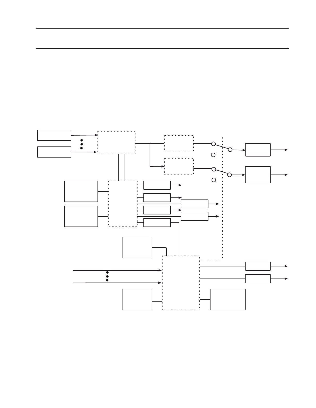
8.2 EXPRESSION BLOCK (EX)
The expression block evaluates a user-specified expression each time it executes. Logical,
arithmetic, and conditional operators can be mixed at will in the expression, with the final
result being scaled to a configured data type. An auxiliary output can provide the result scaled
to another data type. Expressions are entered by the user in algebraic format using ‘C’
symbology for operators and functions and assuming ‘C’ like operator precedence. An
expression can be as simple as a single operand (result data type must be configured in this
case) or as complex as can be fit on the configurator screen.
Block outputs are the result, auxiliary result, and their qualities. A functional block diagram of
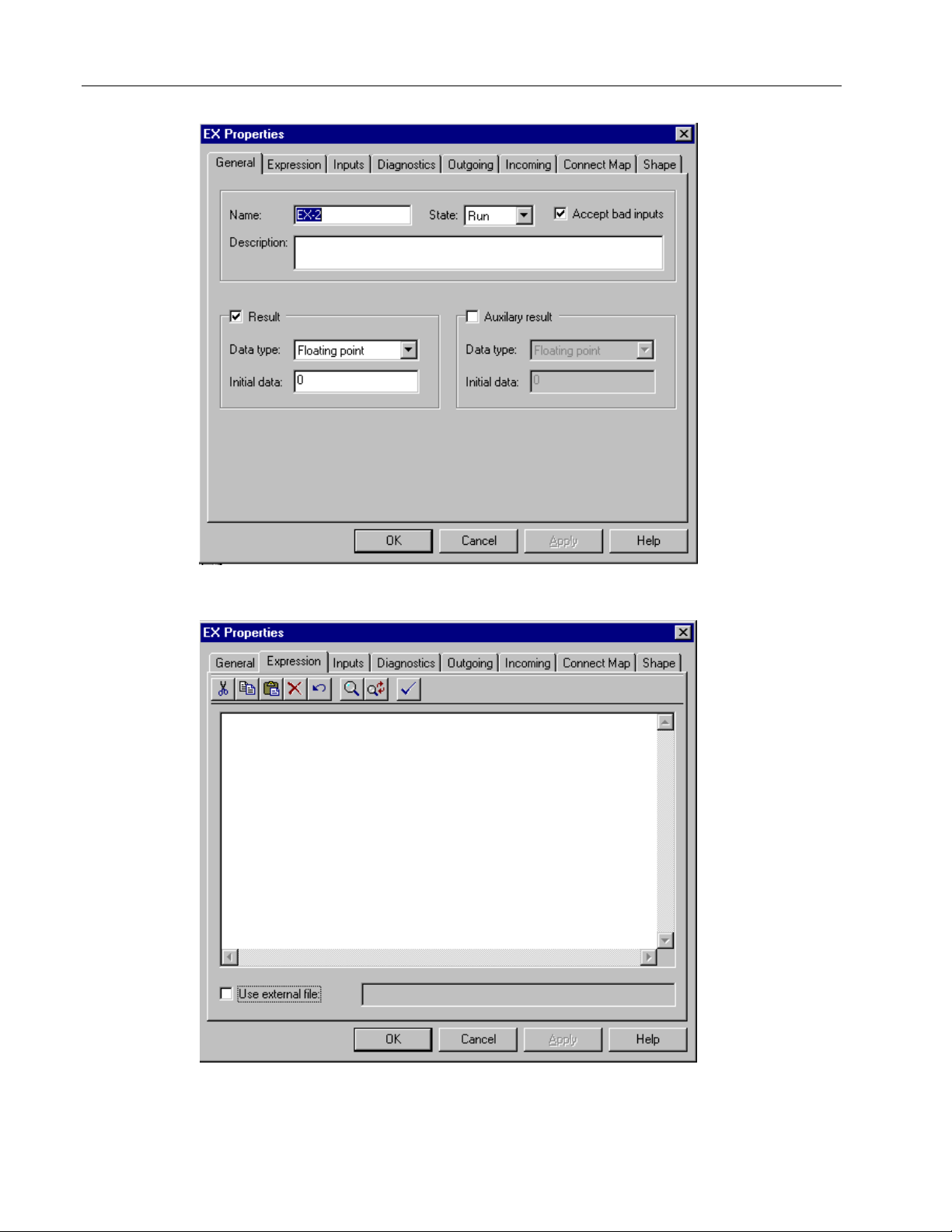
an expression block is shown in Figure 8-1. The displays, which are used to configure the
Expression block, are shown in Figure 8-2 (page 1), Figure 8-3 (page 2) and Figure 8-4 (page
4).
Input No. 1
Expression
Evaluation
Input No. 46
Data Type
Conversion
Logic Functions - Book 2
EXPRESSION BLOCK
GOOD
Result
BAD
Calculation Error
Calculation Error
(ENABLE/
SUPPRESS)
Diagnostic
Group
(NONE, 1 - 7)
Syntax Error
Expression
Error
Bad Inputs
Accepted
(YES/NO)
Input (1) Status
Input (46) S tatus
State
(RUN, HOLD,
OFF, DEBUG)
CERRU
CERRUQ
CERRA
CERRAQ
Data Type
Conversion
ETYPE
EPOS
Quality Check
GOOD
BAD
Set Qual ity BAD
on Calculation
Auxili a ry
Result
RQ
AUXQ
Error?
(YES/NO)
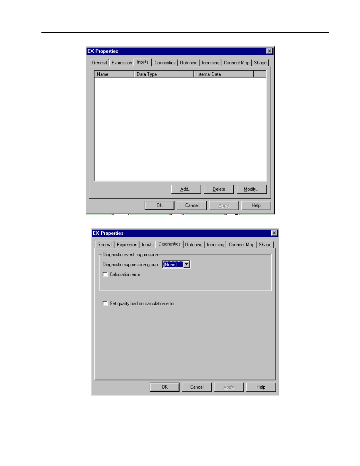
Figure 8-1. Functional Block Diagram, Expression Block
8-3
Page 12
Logic Functions - Book 2
EXPRESSION BLOCK
Figure 8-2. Expression (EX), General Menu
8-4
Figure 8-3. Expression (EX), Expression Editing Display
Page 13
Logic Functions - Book 2
EXPRESSION BLOCK
Figure 8-4. Expression (EX), Inputs Definition Display
Figure 8-5. Expression (EX), Diagnostics Menu
8-5
Page 14

8.2.1 Expression Block Operation
Operator precedence in an expression starts with the unary (single operand) operators and
continues with the binary (double operand) operators. The order of evaluation can be
changed using parentheses or the conditional operators. The order of precedence is:
1. ** (RAISED_TO_THE_POWER)
2. SQRT (SQUARE_ROOT),
MOM (MOMENTARY),
! (Logical NOT),
ABS (ABSOLUTE),
EXP (EXPONENTIAL),
NLOG (NATURAL_LOG),
LOG (LOG_10),
INT (INTEGER)
3. * (TIMES),
/ (DIVIDE),
4. + (PLUS),
– (MINUS)
NOTE: May be interpreted as a sign if immediately befor e mnemonic
(I1+I2). Use I1++I2 or I1+ I2 to be sure.
5. < (LESS_THAN),
> (GREATER_THAN),
<= (LESS_THAN_OR_EQUAL),
>= (GREATER_THAN_OR_EQUAL),
6. == (EQUALS),
!= (UNEQUAL)
7. && (Logical AND)
8. | | (Logical OR)
Logic Functions - Book 2
EXPRESSION BLOCK
8-6
Data Considerations During Evaluation
For Boolean operators, data of any type is considered TRUE if non-zero. For logical
operations, all operands are scaled to DISCRETE during evaluation.
For comparison or arithmetic operations, all operands are scaled to floating point during
evaluation. DATE operands are expanded to include the century and treated as 4 byte
unsigned integers. Prior to applying the operator(s), if the year is in the range 0–89, 100 is
added to make comparisons work properly across the calendar year 2000 (valid for 1990 to
2089). Thus 3/18/95 (stored internally as $5F0312) is treated as $005F0312, or decimal
6226706, while 7/25/2012, (stored internally as $0C0719) is treated as $00700719, or decimal
7341849. HEX and ASCII operands are not allowed.
Evaluation Results
The result of an expression evaluation is DISCRETE if the last operator processed was
logical, or FLOATING POINT if it was arithmetic. This result is then scaled to the configured
data types for the result and auxiliary result outputs of the expression block.
The MOMENTARY Operator
The MOMENTARY operator allows a user to embed an ‘edge detection’ in an expression.
The result of the MOMENTARY operation is TRUE only if its operand was FALSE in the most
recent evaluation and is now TRUE. Note that the MOMENTARY operator is distinct from the
MOMENTARY DISCRETE input data type.
The INTEGER Operator
Page 15
Logic Functions - Book 2
EXPRESSION BLOCK
The INTEGER operator removes the decimal portion of a number, leaving only the integer
portion. It does not round the number. For example, INT(12.678) = 12 and INT(_746.21) =
_746.
The Conditional Operators
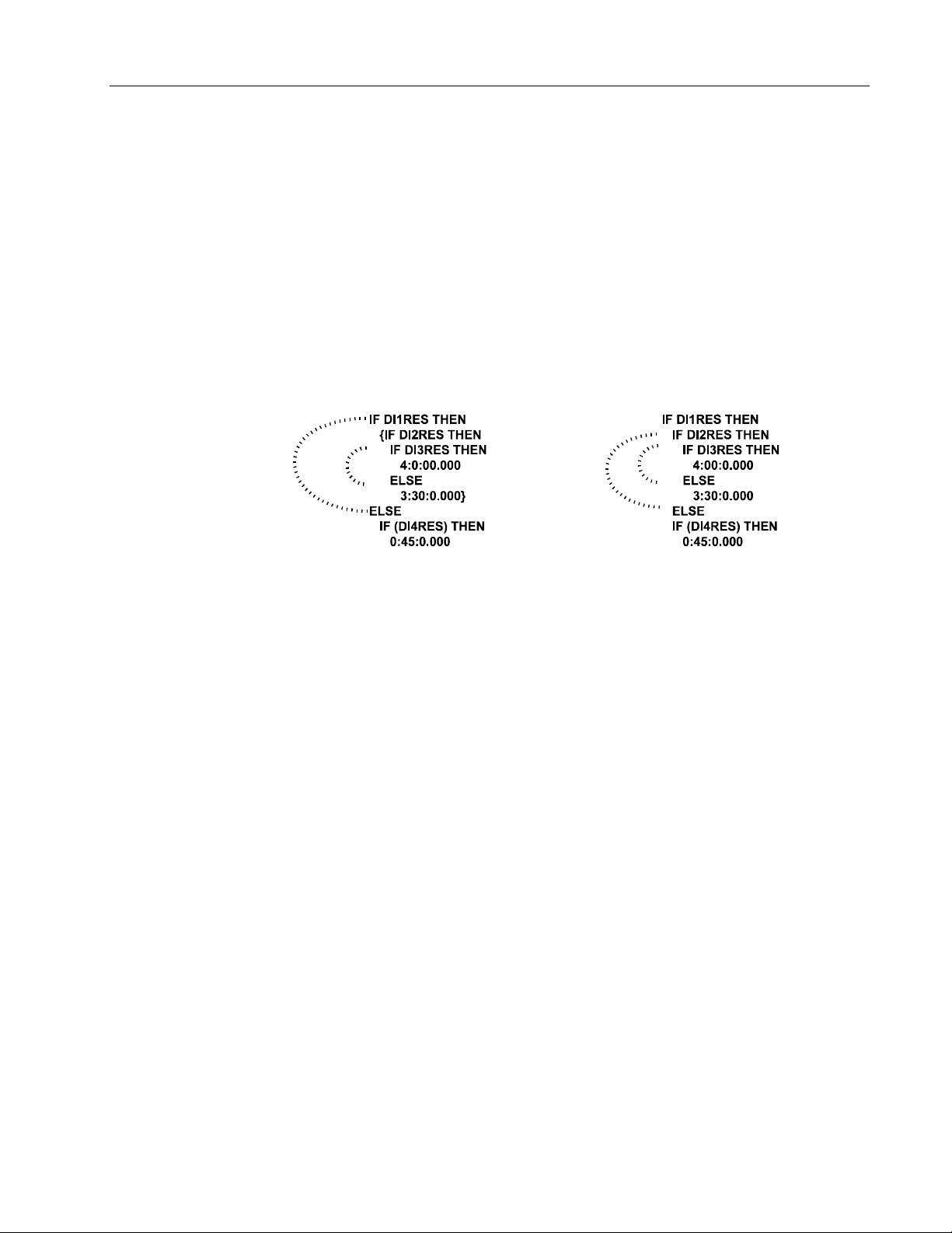
The conditional operators (IF, THEN, and ELSE) let you specify when operations are
evaluated. The IF expression (between the IF and THEN conditionals) is evaluated first.
This expression may be enclosed in parentheses. When the calculated value of the IF
expression is TRUE (non-zero), the THEN expression is evaluated. When it is FALSE (zero),
the ELSE expression is evaluated. The ELSE expression is optional. When the IF
expression evaluates to FALSE and there is no ELSE, the result is not updated. Brackets ({})
should be used for nesting conditionals. If brackets are not present, an ELSE expression is
paired with the last unpaired IF. Notice how the brackets change the pairing of the IF and
ELSE expressions in the following example.
Using Expression Blocks as Recipes
Expression block inputs can be used as a recipe. Any number of local or remote
inputs to the block can be configured without using them in the expression, and for
this purpose only, HEX and ASCII inputs are allowed.
Syntax Errors
When there is a syntax error in the expression or a stack overflow during evaluation (can only
happen with a very deeply nested expression), the expression error diagnostic will be
reported, the results will not be updated and output qualities will be set bad.
Momentary Discrete Local Input
The value of a MOMENTARY DISCRETE local input is changed back to FALSE whenever a
TRUE is found so that it is detected in only one evaluation of an expression. The momentary
discrete feature allows a user to embed a ‘push-button’ in an expression. MOMENTARY
DISCRETE is a unique data type which can only be used as a local input to an expression
block. Another block pointed at this input will see a DISCRETE data type. Setting the local
data to HIGH or LOW configures a local input of this type.
8-7
Page 16

8.2.2 Expression Block Parameters
The mnemonics, valid values, and data types for all fields that may be selected for display
and/or be used in making softwiring connections are listed in Table 8-1. The following further
defines the expression block configuration parameters.
Block Type
EX This is the expression block type. The expression block type code is 15.
Occurrence
1 to 4096 There may be up to 4096 ‘instances’ allowed of the EX block type (subject to
configuration and database size limitations).
Expression
Algebraic expression written in terms of user names for inputs, values (use usual convention
for data types) for constants, ‘C’ symbology for operators and functions. The order of
evaluation of an expression is determined by operator precedence, and parentheses may be
used to change the order of evaluation. An entry is required (there is no default). See
Section 8.2.1 for a description of the expression evaluation operation and valid operators.
Logic Functions - Book 2
EXPRESSION BLOCK
Table 8-1. Expression Block Attributes, Valid Values, Mnemonics, and Data Types
Field Name /
Version VERSION 1, 2, 3 – – R Long State 00
Block Length BLKLEN Number of bytes of database – – R Count 01
Block State
Bad Inputs
Diagnostic Group
Calculation error
Calc. Error Unacked CERRU NO (0), YES (1) – WR Discrete 06
Calc. Error Unacked Quality CERRUQ GOOD (0), BAD (1) – WR Discrete 07
Calc. Error Active CERRA NO (0), YES (1) – WR Discrete 08
Calc. Error Active Quality CERRAQ GOOD (0), BAD (1) – WR Discrete 09
Set quality bad on calculation
error?
Attribute
Mnemonic Valid Values CWR Data Type Attr
STATE RUN(0), HOLD(1), OFF(2),
DEBUG(3)
BADINP Rejected (0), Accepted (1) CWR Discrete 03
SUPPGRP NONE, 1, 2, 3, 4, 5, 6, 7 CWR Long State 04
CERRS ENABLE (0), SUPPRESS (1) CWR Discrete 05
SETQBAD NO (0), YES (1) CWR Discrete 10
CWR Short State 02
8-8
Page 17

Logic Functions - Book 2
EXPRESSION BLOCK
Table 8-1. Expression Block Attributes, Valid Values, Mnemonics, and Data Types (Cont’d)
Field Name /
Error Type ETYPE 0 No Error
Error Position EPOS – – R Count 12
Aux Result
Aux Result Quality AUXQ GOOD (0), BAD (1) – WR Discrete 47
Result
Result Quality
Input 1 I1 CWR 50
Input 2 I2 CWR 51
Input 3 I3 CWR 52
Input 4 I4 CWR 53
Input 5 I5 CWR 54
Input 6 I6 CWR 55
Input 7 I7 CWR 56
Input 8 I8 CWR 57
Input 9 I9 CWR 58
Input 10 I10 CWR 59
…… CWR…
Input 100 I100 CWR 149
…… CWR…
Input 800 I800 CWR 849
Attribute
Mnemonic Valid Values CWR Data Type Attr
– – R Long State 11
Calculation Errors
1 Calc Out of Range
2 SQRT of Negative Num
3 Result Overflow
4 Aux Result Overflow
5 NLog of Non-Pos Num
6 Log of Non-Pos Num
7 Zero Raised to Non-Pos
Num
8 Neg Raised to Noninteger
Syntax Errors
20 Estack Overflow
21 Input Not Found
22 Misaligned Operand
23 Unknown Operand
Type
24 Unknown Constant
Type
25 Misaligned Constant
26 Read from Empty Stack
27 Unknown Operator
AUX CWR 46
RCWR48
RQ GOOD (0), BAD (1) – WR Discrete 49
8-9
Page 18

Logic Functions - Book 2
EXPRESSION BLOCK
00
02 State (STATE) ....................................................................................................................CWR
03 Bad Inputs (BADINP).........................................................................................................CWR
Block Version
The expression block is at version 3. The functional changes are:
All block state changes are reported as events. See Section 2.4.1, State Changes for
additional information.
RUN 0 Normal Operation. Block is executed.
HOLD 1 Block is not executed. Qualities retain previous values.
OFF 2 Block is not executed. Qualities will be BAD.
DEBUG 3 Block is not executed. No fields are updated. All attributes are
See Section 2.3.2, Data Quality for additional information.
Rejected 0 Block checks data quality on its inputs and will only run its algorithm if
Accepted 1 Block runs its algorithm without a check on input quality and output
(VERSION)................................................................................................. – – R
1 Initial Release
2 Added operators for **, ABS, EXP, NLOG, LOG, INT, and the
conditional operators IF, THEN, and ELSE.
3 Added Inputs 21 through 46.
writeable.
its input is good (no action will be taken on the value). T he result will
be held at the previous value and the result quality will be set bad.
quality is set to good.
04 Diagnostic Group (SUPPGRP).........................................................................................CWR
The diagnostic error reported by this block can be grouped for System Event block control of
its reporting. The selections are:
NONE No group assigned.
1 to 7 Defines the diagnostic group number for the diagnostic suppression group
controlled by the System Event block.
05 Calculation Error (CERRS)...............................................................................................CWR
When a calculation error (calculation overflow, divide by zero, square root of negative number
etc.) is detected, the block completes the calculation using some reasonable value (+ or maximum value for overflows, zero for square root of negative number, etc.), reports the
diagnostic error as “CALCULATION ERROR”, and sets the output quality bad if “Set quality
bad on calculation error?” is YES. The diagnostic error will clear and the quality will be set
back to good when a subsequent execution of the block performs a successful calculation. A
calculation error is also reported when improper syntax is found in the expression or when a
stack overflow occurs due to too many nested operations.
ENABLED 0 Calculation error is enabled.
SUPPRESSED 1 Calculation error is suppressed.
06 Calc. Error Unacked (CERRU)..........................................................................................– WR
If the calculation error diagnostic is enabled, the unacknowledged status indicates if the
diagnostic is or is not acknowledged. Only writeable in DEBUG.
8-10
NO 0 Diagnostic error is acknowledged.
YES 1 Diagnostic error is unacknowledged.
Page 19

Logic Functions - Book 2
EXPRESSION BLOCK
07 Calc. Error Unacked Quality (CERRUQ)......................................................................... – WR
If the calculation error diagnostic is enabled, this status indicates if the quality of the
unacknowledged diagnostic is GOOD or BAD. Only writeable in DEBUG.
GOOD 0 Quality when the loop block is RUN or HOLD.
BAD 1 Quality when the loop block is OFF.
08 Calc. Error Active (CERRA) ............................................................................................. – WR
If the calculation error diagnostic is enabled, the active status indicates if the diagnostic is
active even after acknowledgement. Only writeable in DEBUG.
NO 0 Diagnostic error is not active.
YES 1 Diagnostic error is active.
09 Calc. Error Active Quality (CERRAQ)............................................................................. – WR
If the calculation error diagnostic is enabled, this status indicates if the quality of the active
diagnostic is GOOD or BAD. Only writeable in DEBUG.
GOOD 0 Quality when the loop block is RUN or HOLD.
BAD 1 Quality when the loop block is OFF.
10 Set quality bad on calculation error? (SETQBAD) .........................................................CWR
The result quality can be affected by a calculation error as follows. Note that result quality is
always set bad on a syntax error.
NO 0 Result quality is not affected by a calculation error.
YES 1 Quality is set BAD when a calculation error occurs.
11
Error Type
When an error occurs, a code indicating the type of error detected is stored in the block for
user reference. In the case of a configuration error, the location of the error is also stored
(EPOS).
NO ERROR 0
Calculation Errors:
CALC OUT OF RANGE 1 There was an overflow or underflow somewhere
SQRT OF NEGATIVE NUM 2 Calculation was completed using 0 for the square
RESULT OVERFLOW 3 Result is error free, but its value is too large to fit
(ETYPE) ...........................................................................................................– – R
in the calculation. Calculation was completed
using max or min value for that intermediate
result.
root.
the configured data type. The result is set to the
maximum or minimum value for the configured
data type.
AUX RESULT OVERFLOW 4 Same as result overflow.
NLOG OF NON POS NUM 5 Attempt to calculate the natural log of a number
less than or equal to zero. Calculation was
completed using 0 for the natural log
intermediate result.
8-11
Page 20

Logic Functions - Book 2
EXPRESSION BLOCK
LOG OF NON POS NUM 6 Same as NLog of non-positive number.
ZERO RAISED TO NON POS 7 Attempt to calculate zero to a non-positive
power.
NUM Calculation was completed using 0 for the inter-
mediate result.
NEG RAISED TO NON 8 Attempt to calculate a negative number to a
INTEGER non-integer power. Calculation was completed
using 0 for the intermediate result.
Syntax Errors:
ESTACK OVERFLOW 20 There was not sufficient evaluation stack to
complete the calculation.
INPUT NOT FOUND 21 One of the input operands was not found.
MISALIGNED OPERAND 22 Input operand token at odd address.
UNKNOWN OPERAND TYPE 23 Unknown data type found for input operand.
UNKNOWN CONSTANT TYPE 24 Unknown data type found for constant operand.
MISALIGNED CONSTANT 25 Multiple byte constant at odd address.
READ FROM EMPTY STACK 26 An operator was found with no operand(s)
remaining on the evaluation stack.
UNKNOWN OPERATOR 27 An unknown operator was found.
12
46 Aux Result (AUX)............................................................................................................... CWR
47 Aux Result Quality (AUXQ)..............................................................................................– WR
Error Position
This is the offset into the expression where the error was detected.
This is the block auxiliary result after the expression is evaluated. During startup, this is the
auxiliary result initial data value. The initial data value must match the auxiliary result data
type. If NONE is selected, no initial data is placed in the auxiliary result.
The auxiliary result can be enabled (box checked) or disabled (box not checked) by
configuration. When enabled, the auxiliary result and auxiliary result quality attributes are
made part of the database. When disabled, the auxiliary result and auxiliary result quality
attributes are removed from the database.
The auxiliary result can be any of the following data types: Floating Point, Count, Discrete,
Short State, Long State, Msec Time.
This data quality field will go BAD if any of the blocks quality checks become active.
(EPOS).......................................................................................................– – R
8-12
Page 21

Logic Functions - Book 2
EXPRESSION BLOCK
48 Result Initial Value (R).......................................................................................................CWR
This is the block result after the expression is evaluated. During startup, this is the result initial
data value. The initial data value must match the result data type. If NONE is selected, a zero
is placed in the result.
The result can be enabled (box checked) or disabled (box not checked) by configuration.
When enabled, the result and result quality attributes are made part of the database. When
disabled, the result and result quality attributes are removed from the database.
The result can be any of the following data types: Floating Point, Count, Discrete, Short State,
Long State, Msec Time. The selection of AUTO in the configurator allows the configurator to
determine if the result is either discrete or floating point (Expression Block Version 1 only).
The selection depends on the final operation performed in evaluating the expression. If you
upgrade your database from version 1, AUTO will change to Floating Point and a warning will
appear in the configurator.
49 Result Quality (RQ)...........................................................................................................– WR
This data quality field will go BAD if any of the blocks quality checks become active.
50 Input 1 (I1) ..........................................................................................................................CWR
through
95 Input 46 (I46) ......................................................................................................................CWR
The input values are writeable only if the data is local. The user name for an input is an eight
(8) character alphanumeric used to identify the input in the expression. The default names
are I1 through I46. Invalid characters are: operators, space, comma, period.
NONE Indicates an unused input. Inputs used in the expression cannot be
NONE.
LSP Any external variable, any data type.
Local Data Any local data, any data type. Local data can use a unique data type,
Momentary Discrete, as a local input to an expression block. Another
block pointed at this input will see a DISCRETE data type. Setting
the local data to HIGH or LOW configures a local input of this type.
HEX and ASCII inputs can be specified for recipe or data storage
applications, but cannot be referenced in the expression. See
Section 8.2.1, Expression Block Operation.
8-13
Page 22
8.2.3 Typical Block Connections for Expression Block
Typical softwiring block structures used on softwiring diagrams are shown in Figure 8-6.
Logic Functions - Book 2
EXPRESSION BLOCK
VCI1
Result
VCI2
Result
VCI3
Result
Logic to select value
(other expression block)
DI1
Result
DI2
Result
EX2 (BADINP=YES)
COUNT (Input_1)
COUNT
R
R
R
R
R
Input Selector Example
EX1
Input_1
Input_2
Input_3
Input_4
SELECT (Input_5)
(SELECT==1)*Input_1+
(SELECT==2)*Input_2+
(SELECT==3)*Input_3+
(SELECT>1
Input_4
R
SELECT>3) *
Counter Example
EX1 (BADINP=NO)
Input_1
RESET (Input_2)
COUNT (Input_3)
!RESET * (COUNT +
MOM(Input_1))
R
R
Selector Example Notes
This example selects
between three inputs b y
using another expression
block that produces a
select value . If none of the
three are selected, then
the previous input (input
4) is selected.
Selected Signal
Counter Example Notes
This example counts a
digital input with reset
provided by another digital
input. The seco nd
expression block is set up
to keep the first
expression from latching
quality BAD.
Count
8-14
VCI1
Result
DI2
Result
TM1*
High Limit Status
High Limit
Time
Tota lize r Example Notes
This example totalizes an
input (i.e. gpm) with reset
provided by a digital input.
The second expression
block is set up to keep the
first expression from
latching quality BAD.
R
R
R
HLSTAT
HILIM
TIME
Totalizer Example
EX1 (BADINP= N O)
GPM (Input 1)
RESET (Input 2)
MIN (Input 3)
TOTAL (Input 4)
!RESET * (TOTAL + GPM * MIN)
EX2 (BADINP= YES)
HLST AT (Input 1)
HILIM (Input 2)
TIME (Input 3)
EX3
TIME (Input 1)
TIME
LAST (Input 4)
(HLSTAT * (HILIM - LAST +
TIME) + !HLSTAT * (TIME LAST)) / 60000.0
Figure 8-6. Typical Block Connections for Expression Block
Totalized Value
R
Page 23

8.2.4 Expression Block Events
The event codes (and their suggested text messages) for the expression block are given
below. See the referenced database attributes (in brackets) for additional information. See
System Event Block, Logic Functions - Book 1, IB-23G600 for a description of event
transitions.
0 BLOCK STATE SET TO RUN
1 BLOCK STATE SET TO HOLD
2 BLOCK STATE SET TO OFF
3 BLOCK STATE SET TO DEBUG
4 CALCULATION ERROR (5)
8.2.5 Example 1: Using Expression Blocks to Store Trend Data
Expression blocks can be used for local data storage. You may want to do this for two
reasons: either to allow trend storage without tying up communication links to the host, or to
allow the MODCELL to accumulate data locally for later upload even if the communication line
(for example a modem) is disconnected for a period. For remote installations, another benefit
of trending using the expression block is portability. The data is stored in main memory, and
is therefore backed up onto the Memory Module. The trend data can therefore, be removed in
the Memory Module and taken elsewhere for analysis with a blank Memory Module left on the
MODCELL for another weeks or months data collection.
Logic Functions - Book 2
EXPRESSION BLOCK
For analog variables, data is typically stored as period averages for a configured number of
periods (trend cycles). The application engineer must pick the number of variables to be
stored and the number of instantaneous values to store for the "fastest" trend period and
finally, the application engineer needs to specify how many averages to store for the slower
time periods. This is best done in table form as shown below.
Setup for Storing Trend Data Using Expression Blocks
Variable Scan Rate
(seconds)
FC-101 5
FC-102 5
FC-103 5
TC-100 5
TC-101 5
Trend Cycle 1 Trend Cycle 2 Trend Cycle 3 Trend Cycle 4
(20)
Five Second
Samples
√
√
√√
√√√√
√√√√
(30)
One Minute
Averages
(24)
Fifteen Minute
Averages
(24)
One Hour
Averages
8-15
Page 24
Logic Functions - Book 2
EXPRESSION BLOCK
In this example, all variables are on the same scan rate. If the variables have different scan
rates, the historian loop can include some expression blocks to average or sample the faster
variables so all variables are trended at the same resolution and time base. Alternately, the
entire historian can be run at the fastest frequency. The number of samples in each trend
cycle in this example is kept less than 30 to fit conveniently on the LCP screen for display of a
trend. More or fewer averages can be included in a given trend cycle as required, and the
number and size of the trend cycles can be adjusted. Trends can be based on sample
averages, maximums or minimums, based on the expression block.
A typical Analog Historian/Trending Loop is shown below. The instantaneous value is passed
back in the "bucket Brigade" of Trend Cycle 1. The application engineer specifies how many
buckets to put in the brigade (note the execution order). The last block (that is the block
holding the oldest variable) is the first block in the loop to run.
AI
TREND CYCLE 1
Loop Execution
Every 5 sec.
EX-1
EX-18-2
EX-19
EX-20
Out=In
TREND CYCLE 2
Loop Execution
Every Minute
EX-1
EX-28-2
EX-29
EX-30
Out= Σ In/20
First
15 Blocks
Only
TREND CYCLE 3
Loop Execution
Every 15 Minutes
EX-1
EX-22-2
EX-23
EX-24
Out= Σ In/15
TREND CYCLE 4
Loop Execution
EX-22-2
EX-23
EX-24
Out= Σ In/4
First
4 Blocks
Only
Trend Cycle 2 is constructed the same way, except the first block (the one holding the most
current value) is an averaging block that takes the average of several blocks in the Trend
Cycle 1 "bucket brigade." This block can include logic to correct its output if one or more of
the input variables from the prior trend cycle contain "bad Quality" data flags. The process
repeats for Trend Cycle 3 and for as many trend cycles as are needed.
8.2.6 Example 2: Using IF-THEN-ELSE Statements in Expression Blocks
IF-THEN-ELSE statements make it much easier to write readable expressions for sequence
logic. For example, if you want an expression block to identify which of three tanks is the
lowest to determine which will be filled next, you could use the following formula in an
expression block:
Every Hour
EX-1
8-16
If (L1<L2) && (L1<L3) then 1 else
If (L2<L1) && (L2<L3) then 2 else
If (L3<L2) && (L3<L1) then 3
Page 25
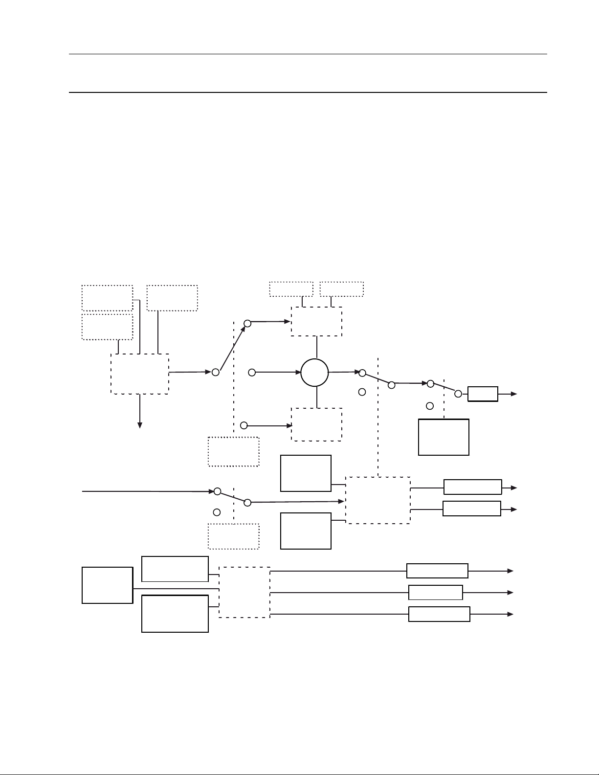
8.3 INPUT COMMUNICATION BLOCK (IC)
The input communication block is used to receive data from the output communication block,
or output communication block channel for MOD 30 controllers and recorders, or another
instrument on the ICN via communication messages. The block specifies the source, data
type, and whether quality is to be received with the data. It also has the capability of receiving
other MOD 30 data types and storing the data as a MODCELL data type; for example,
continuous may be received and floating point stored. A mode switch is available so that the
data being received can be ignored, and allow an operator to manually change the data.
Finally, two diagnostics are provided. One diagnostic (source diagnostic) is provided to detect
a configuration error within either the block or within an Output Communication block in
another instrument. The other (timeout diagnostic) is provided to detect a break in the
communications that has halted the continual flow of data from the source.
Block outputs are the data and data quality and diagnostic errors and error quality. A
functional block diagram of a input communication block is shown in Figure 8-7. Displays used
to configure the Input Communication block are shown in Figures 8-8 through Figure 8-10.
Logic Functions - Book 2
INPUT COMMUNICATION BLOCK
Instrument
Number
Port
Number
Input Data
Quality
Diagnostic
Group
(None, 1 - 7)
Occurrence
Data
Source
TO:
Diagnostic
Errors
Not Receivin g
Data (Enab/Supp)
Unexpected Data
(Enab/Supp)
Number
Receiving
YES
NO
Data
Type
Receive
Quality
Diagnostic
Errors
Top Bottom
Continuous
All others
ASCII or
HEX
Range
OR
Maximum
Field Size
(1-126)
Bad Inputs
Accepted
(YES)
State (RUN,
HOLD, OFF,
DEBUG)
GOOD
BAD
Quality Check
AUTO
Result
MANUAL
Mode
Result Qual ity
Error Quality
Error Count
Active Errors
Unacked Errors
Figure 8-7. Functional Block Diagram, Input Communication Block
8-17
Page 26

Logic Functions - Book 2
INPUT COMMUNICATION BLOCK
Figure 8-8. Input Communication Block (IC), General Menu
8-18
Figure 8-9. Input Communication Block (IC), Data Source Menu
Page 27
Logic Functions - Book 2
INPUT COMMUNICATION BLOCK
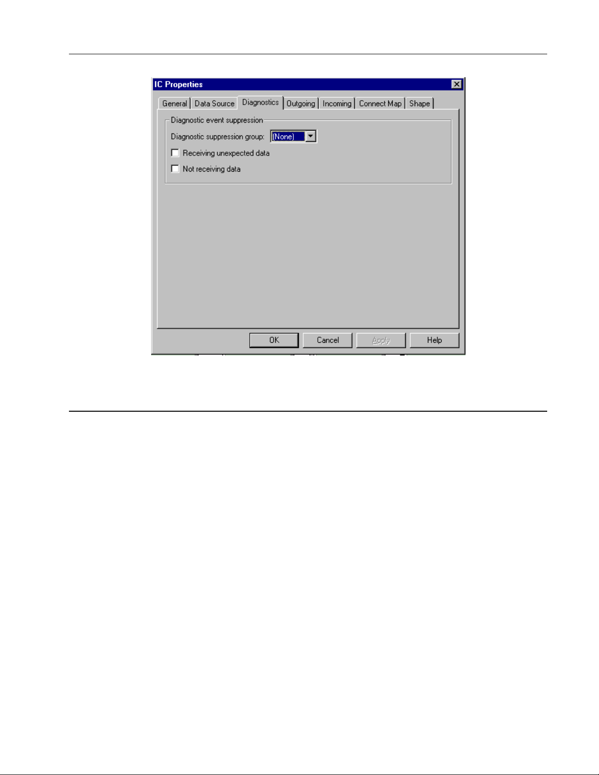
Figure 8-10. Input Communication Block (IC), Diagnostics Menu
8.3.1 Input Communication Block Operation
The Input Communication block is a loop function block that checks the ICN receive buffer to
determine if new information has been received, and also whether any source or time-out
diagnostic errors have been detected. If no new data has been received for 2 seconds, then
the timeout diagnostic is detected. When in auto and this diagnostic is detected, the result
quality is set bad. The current status of both diagnostics is passed to the System Event block
for processing. If new data has been received and the mode is auto, then the result field is
updated. If quality is being received with the data, then the result quality field is updated with
that value. If only the data is being received, the quality is set good.
On a warm or cold start, if the block mode is auto and the block/loop state is not debug, data
quality is set to bad and the receive buffer is cleared. Additionally, on a cold start, the status
of diagnostics are cleared and their qualities set BAD.
8-19
Page 28

Logic Functions - Book 2
INPUT COMMUNICATION BLOCK
8.3.2 Input Communication Block Parameters
The mnemonics, valid values, and data types for all fields that may be selected for display
and/or be used in making softwiring connections are listed in Table 8-2. The following further
defines the input communication block configuration parameters.
Block Type
IC This is the input communication block type.
Occurrence
1 to 32 There may be up to 32 ‘instances’ allowed of the IC block type.
Data Source....................................................................................................................... C – –
The data source information is configured in this block and is used to define the
source of the incoming data.
Instrument Number Instrument Numbers are: 0 to 15. This number represents the
ICN address of the instrument sending the data.
Port Number Port Numbers are: 1 to 3. This number represents which ICN
block should receive the data.
Occurrence Number Occur rence Numbers are: 1 to 16 for MOD 30 XL and Recorder
or 1 to 32 for MOD 30 SLU and MODCELL instruments. This
number represents the output communication point in the
instrument sending the data.
Receive Quality? NO - Data quality is not sent and not expected from MOD 30
instruments
YES - Data quality is sent and is with the data expected from
MODCELL instruments.
Data Type Format of the data to be received may be: CONTINUOUS,
DISCRETE, SHORT STATE, DATE, TIME, CTRL MODE,
LONG STATE, FLOAT PT, ASCII, or MSEC TIME, HEX,
COUNT.
Range Range applies to continuous data only. Enter range in floating
point. The range is applied to the continuous data before it is
stored.
Bottom Indicates the 0% value(low). Default is 0.00000.
8-20
Top Indicates the 100% value (high). Default is
100.00000
Maximum Field Size Indicates the maximum number of bytes or characters the data
field can take. Valid values are 1 to 126. This parameter
applies only when receiving hex bytes or ASCII characters.
Page 29

Logic Functions - Book 2
INPUT COMMUNICATION BLOCK
02
State
(STATE).....................................................................................................................CWR
All block state changes are reported as informational events. See Section 2.4.1,
State Changes for additional information.
RUN 0 Normal Operation. Block is executed.
HOLD 1 Block is not executed. Qualities retain previous values.
OFF 2 Block is not executed. Qualities will be BAD.
DEBUG 3 Block is not executed. No fields are updated. All attributes are
writeable.
Table 8-2. Input Communication Block Attributes, Valid Values, Mnemonics, and Data Types
Field Name /
Version VERSION 1 – – R Long State 00
Block Length BLKLEN – – R Count 01
Block State
Bad Inputs Accepted
Diagnostic Group
Receiving unexpected data
Unacked Source Diag SRCUNACK FALSE, TRUE – WR Discrete 06
Unacked Source Diag Quality SRCUNQ GOOD (0), BAD – WR Discrete 07
Not receiving data
Unacked Timeout Diag TOUNACK FALSE, TRUE – WR Discrete 09
Unacked Timeout Diag Qual TOUNACKQGOOD (0), BAD – WR Discrete 10
Timeout Diag Active TOACT CLEAR (0), ACTIVE (1) – WR Discrete 11
Timeout Diag Active Quality TOACTQ GOOD (0), BAD – WR Di screte 12
Source Diag Counter SRCCNT 0-65535 – WR Count 13
Source Diag Counter Quality SRCCNTQ GOOD (0), BAD – WR Discrete 14
Data Update Mode
Initial Data (Result)
Result Quality
Attribute
Mnemonic Valid Values CWR Data Type Attr
STATE RUN(0), HOLD(1), OFF(2),
DEBUG(3)
BADINP Accepted (1) – – R Discrete 03
SUPPGRP NONE, or 1 to 7 CWR Long State 04
SRCSUPP ENABLE, SUPPRESS CWR Discrete 05
TOSUPP ENABLE, SUPPRESS CWR Discrete 08
MODE MANUAL, AUTO CWR Discrete 15
R CWR any 16
RQ GOOD (0), BAD – WR Discrete 17
CWR Short State 02
03
04
Bad Inputs
This block runs with bad inputs accepted. There is no check on input quality. Result quality
depends on how receive quality was configured. See result quality attribute for possible
conditions. See Section 2.3.2, Data Quality for additional information.
Diagnostic Group
The diagnostic errors reported by this block can be grouped for System Event block control of
their reporting. The selections are:
NONE No group assigned.
1 to 7 The number of the diagnostic suppression group as controlled by the System
(BADINP).........................................................................................................– – R
(SUPPGRP) .........................................................................................CWR
Event block.
8-21
Page 30

Logic Functions - Book 2
INPUT COMMUNICATION BLOCK
05
06
07
Receiving unexpected data
Indicates whether the source diagnostic error is enabled or suppressed. This diagnostic is
provided to detect a configuration error (source or data type incorr ect) within either this block
or within an Output Communication block in another instrument.
ENABLE 0 The receiving unexpected data (source) diagnostic error is enabled.
SUPPRESS 1 The receiving unexpected data (source) diagnostic error is
Unacked Source Diagnostic
If the receiving unexpected data diagnostic is enabled, the unacknowledged status indicates if
the diagnostic error is or is not acknowledged.
NO 0 Diagnostic error is acknowledged.
YES 1 Diagnostic error is unacknowledged.
Unacked Source Diagnostic Quality
If the receiving unexpected data diagnostic is enabled, this status indicates if the quality of the
unacknowledged diagnostic is GOOD or BAD. Only writeable in DEBUG.
GOOD 0 Quality when the block (or its controlling loop) is RUN or HOLD.
BAD 1 Quality when the block (or its controlling loop) is OFF.
(SRCSUPP).........................................................................CWR
When this diagnostic is detected, the diagnostic message
RECEIVING UNEXPECTED MESSAGE is reported.
suppressed. Acknowledgement status remains clear.
(SRCUNACK).....................................................................– WR
(SRCUNQ)............................................................– WR
08
09
10
Not receiving data
Indicates whether the timed-out diagnostic error is enabled or suppressed. This diagnostic is
provided to detect a break in the communications that has halted the continual flow of data
from the source. If no new data has been received for 2 seconds, then the timeout diagnostic
is detected.
ENABLE 0 The timed-out diagnostic error is enabled. When this diagnostic is
SUPPRESS 1 The timed-out diagnostic error is suppressed. Acknowledgement
Unacked Timeout Diagnostic
If the not receiving data diagnostic is enabled, the unacknowledged status indicates if the
diagnostic error is or is not acknowledged.
NO 0 Diagnostic error is acknowledged.
YES 1 Diagnostic error is unacknowledged.
Unacked Timeout Diagnostic Quality
If the not receiving data diagnostic is enabled, this status indicates if the quality of the
unacknowledged diagnostic is GOOD or BAD. Only writeable in DEBUG.
GOOD 0 Quality when the block (or its controlling loop) is RUN or HOLD.
BAD 1 Quality when the block (or its controlling loop) is OFF.
(TOSUPP)........................................................................................... CWR
detected, the result quality is set BAD and the diagnostic message
NOT RECEIVING DATA is reported.
status remains clear.
(TOUNACK)......................................................................– WR
(TOUNACKQ) .....................................................– WR
8-22
Page 31

Logic Functions - Book 2
INPUT COMMUNICATION BLOCK
11
12
13
14
15
Timeout Diagnostic Active
If the not receiving data diagnostic is enabled, the active status indicates if the diagnostic error
is active even after acknowledgement.
CLEAR 0 Diagnostic error is not active.
ACTIVE 1 Diagnostic error is active.
Timeout Diagnostic Active Quality
If the not receiving data diagnostic is enabled, this status indicates if the quality of the active
diagnostic is GOOD or BAD. Only writeable in DEBUG.
GOOD 0 Quality when the block (or its controlling loop) is RUN or HOLD.
BAD 1 Quality when the block (or its controlling loop) is OFF.
Source Diagnostic Counter
0-65535. This is a free running count of the source diagnostic errors detected.
Source Diagnostic Counter Quality
BAD, GOOD. Indicates the quality of the source diagnostic error counter. Quality is set to
BAD when the block (or its controlling loop) is OFF.
Data Update Mode
Indicates how the data being received is updated. Switching mode is an informational event.
MANUAL 0 In manual the result data and quality are not updated by the source.
(MODE)...............................................................................................CWR
(TOACT)............................................................................... – WR
(TOACTQ)............................................................... – WR
(SRCCNT)........................................................................... – WR
(SRCCNTQ)........................................................... – WR
The result data is operator writeable in manual. When the block
mode is set to manual from auto, the event message BLOCK MODE
SET TO MANUAL is reported.
16
17
AUTO 1 In auto the result data and quality are updated by the source. When
the block mode is set to auto from manual, the event message
BLOCK MODE SET TO AUTO is reported.
Initial Data Result
This is the block output value after ranging and mode is applied. During startup, this is the
initial data value.
Result Quality
The result quality field depends on how receive quality was configured. The possible
conditions are:
Result quality is GOOD when receiving just data.
•
Result quality is the received quality when receive quality is configured as YES.
•
Result quality is BAD when no data is received for two or more seconds.
•
(R) ........................................................................................................CWR
(RQ)........................................................................................................... – WR
8-23
Page 32

Logic Functions - Book 2
INPUT COMMUNICATION BLOCK
8.3.3 Typical Block Connections for Input Communication Block
Typical softwiring block structures used on softwiring diagrams are shown in Figure 8-11. For
input communications, data quality may or may not be received (see result quality attribute).
Continuous
Data
Data Source (ICN1,
Instrument 2, OC3)
IC1
Result
Result Quality
Mode
Figure 8-11. Typical Block Connections for Input Communication Block
8.3.4 Input Communication Block Events
The event codes (and their suggested text messages) for the input communication block are
given below. See the referenced data base attributes (in brackets) for additional information.
See System Event Block, Logic Functions - Book 1, IB-23G600 for a description of event
transitions.
0 BLOCK STATE SET TO RUN
1 BLOCK STATE SET TO HOLD
2 BLOCK STATE SET TO OFF
3 BLOCK STATE SET TO DEBUG
4 RECEIVING UNEXPECTED MESSAGE (5)
5 NOT RECEIVING DATA (8)
6 BLOCK MODE SET TO MANUAL
7 BLOCK MODE SET TO AUTO
R
RQ
MODE
Softwiring connection to
another block with quality
logically attached.
Operator indication
of Mode
8-24
Page 33

8.4 OUTPUT COMMUNICATION BLOCK (OC)
The output communication block is used to transmit data to an input communication block, or
input communication block channel for MOD 30 controllers and recorders, of other
instruments on the ICN via communication messages. The block specifies the data
destination, data type, and whether quality is to be sent with the data. It also has the
capability of sending MOD30 data types by converting the data from a MODCELL data type;
for example, floating point may be input and continuous sent.
Block outputs are result and result quality. A functional block diagram of an output
communication block is shown in Figure 8-12. The displays used to configure the Output
Communication block is shown in Figures 8-13 and 8-14.
Logic Functions - Book 2
OUTPUT COMMUNICATION BLOCK
Local Value
LSP
Input
Bad Inputs
Accepted
(YES)
State (RUN,
HOLD, OFF,
DEBUG)
Input Data Quality
NONE
GOOD
BAD
Quality Check
GOOD
AUTO
MANUAL
AUTO
MANUAL
Mode
Result
Lock
Comm Lock
(IF Block)
Result
Quality
Unlock
Unlock
Lock
ASCII or HEX
Data
Type
Top Bottom
Floating Pt
All Others
Send
Quality
YES
NO
Range
OR
Maximum
Field Size
(1-126)
Destination
Instrument
Number
Port
Number
Occurrence
Number
Data
Figure 8-12. Functional Block Diagram, Output Communication Block
8-25
Page 34

Logic Functions - Book 2
OUTPUT COMMUNICATION BLOCK
Figure 8-13. Output Communication Block (OC), General Menu
8-26
Figure 8-14. Output Communication Block (OC), Data Destination Menu
Page 35

8.4.1 Output Communication Block Operation
The Output Communication block is a loop function block that writes the ICN send buffer every
time the instrument gains access to transmit (approximately every 250 milliseconds).
When the mode is in auto, the input and its quality are fetched, and placed in the result and
result quality fields respectively. If the data was updated, from either the input source or a
write message (manual only), then the message buffer is updated for the next transmission
cycle. The data will not be updated when the communication lock is true.
On a warm start, a message is formatted with the current data value. On a cold start, data
quality is set to bad, the send buffer is cleared, and nothing is sent until the block executes
and the communication lock is false.
8.4.2 Output Communication Block Parameters
The mnemonics, valid values, and data types for all fields that may be selected for display
and/or be used in making softwiring connections are listed in Table 8-3. The following further
defines the output communication block configuration parameters.
Logic Functions - Book 2
OUTPUT COMMUNICATION BLOCK
Block Type
OC This is the output communication block type.
Occurrence
1 to 32 There may be up to 32 ‘instances’ allowed of the OC block type.
Table 8-3. Output Communication Block Attributes, Valid Values, Mnemonics, and Data Types
Field Name /
Version VERSION – – R Long State 00
Block Length BLKLEN – – R Count 01
Block State
Bad Inputs Accepted
Data Update Mode
Initial Data (Result)
Result Quality
Input INPUT LSP, local data CWR any 07
Attribute
Data Destination ................................................................................................................C – –
The data source information is configured in this block and is used to define the source of the
incoming data.
Instrument Number Instrument Numbers are: 0 to 15. T his number represents the
Mnemonic Valid Values CWR Data Type Attr
STATE RUN, HOLD, OFF, DEBUG CWR Short State 02
BADINP YES – – R Discrete 03
MODE AUTO, MANUAL CWR Discrete 04
R local data CWR any 05
RQ GOOD, BAD – WR Discrete 06
ICN address of the instrument receiving the data.
Port Number Port Numbers are: 1 to 3. This number represents which ICN
block should transmit the data.
Send Quality NO - Data quality is not sent with the data. Quality data can
not processed by MOD 30 instruments
YES - Data quality is sent with the data (for MODCELL
instruments).
8-27
Page 36

Logic Functions - Book 2
OUTPUT COMMUNICATION BLOCK
Occurrence Number Occurrence Numbers are: 1 to 16 for MOD 30 XL and
Data Type Format of the data to be sent may be: COUNT,
Range................................................................................................................................. C – –
Range applies to continuous data only. Enter range in floating point. The range is
applied to the continuous data before it is sent. The top value cannot equal the
bottom value.
Bottom Indicates the 0% value (low). Default is 0.00000.
Top Indicates the 100% value (high). Default is 100.00000
Initial Data Type.................................................................................................................C – –
The format of the initial data may be: FLOAT, ASCII, MSEC TIME, HEX, COUNT,
DISCRETE, SHORT STATE, DATE, or LONG STATE.
Recorder or 1 to 32 for MOD 30 SLU. This number represents
the output communication point in the instrument receiving the
data.
CONTINUOUS, DISCRETE, STATE, DATE, TIME, CMODE,
LSTATE, FLOAT, ASCII, HEX, or MSEC TIME.
The data fields (Input, Result, and Data Type) must all be
compatible.
Maximum Field Size..........................................................................................................C – –
Indicates the maximum number of bytes or characters the data field can take. Valid
values are 1 to 126. This parameter applies only when sending hex bytes or ASCII
characters.
02 State (STATE) ....................................................................................................................CWR
All block state changes are reported as informational events. See Section 2.4.1,
State Changes for additional information.
RUN Normal Operation. Block is executed.
HOLD Block is not executed. Qualities retain previous values.
OFF Block is not executed. Qualities will be BAD.
DEBUG Block is not executed. No fields are updated. All attributes are writeable.
03 Bad Inputs Accepted (BADINP) .......................................................................................– – R
This block runs with bad inputs accepted set to YES. There is no check on input
quality and output quality is set to good. See Section 2.3.2, Data Quality for
additional information.
04 Data Update Mode (MODE) ..............................................................................................CWR
Indicates how the data being sent is updated. Switching mode is an informational
event.
AUTO In auto the result data and quality are updated by the source. When
the block mode is set to auto from manual, the event message
BLOCK MODE SET TO AUTO is reported.
8-28
MANUAL In manual the result data and quality are not updated by the source.
The result data is operator writeable in manual. When the block
mode is set to manual from auto, the event message BLOCK MODE
SET TO MANUAL is reported.
Page 37

Logic Functions - Book 2
OUTPUT COMMUNICATION BLOCK
05 Initial Data
Result
(R).........................................................................................................CWR
This is the block output value after ranging and mode are applied. During startup,
this is the initial data value. The data must match the initial data type.
06
Result Quality
(RQ) ............................................................................................................ – WR
This data quality field will go BAD if any of the blocks quality checks becomes
active.
07 Input
(INPUT)......................................................................................................................CWR
This is the block input value.
LSP Any logical source pointer that matches the configured data type. The field is
not writeable when a logical source pointer is selected.
local data Any value that matches the configured data type. The field is writeable.
8.4.3 Typical Block Connections for Output Communication Block
Typical softwiring block structures used on softwiring diagrams are shown in Figure 8-15.
EX1
Result
Result Qualit y
OC1
Result
Result Quality
Mode
R
RQ
MODE
Data Destination (ICN1,
Instrument 1, IC1)
Operator indication of
data quality and Mode
Result
Operator write access to set Mode and write data.
Figure 8-15. Typical Block Connections for Output Communication Block
8.4.4 Output Communication Block Events
The event codes (and their suggested text messages) for the output communication block are
given below. See data base attributes for additional information. See the system event block
for event transition information.
0 BLOCK STATE SET TO RUN
1 BLOCK STATE SET TO HOLD
2 BLOCK STATE SET TO OFF
3 BLOCK STATE SET TO DEBUG
4 BLOCK MODE SET TO MANUAL
5 BLOCK MODE SET TO AUTO
8-29
Page 38

Logic Functions - Book 2
OUTPUT COMMUNICATION BLOCK
8-30
Page 39

8.5 LINEARIZATION BLOCK (LN)
The linearization block produces a linearized value of a floating-point input signal from a
specified source, or from a local data value. Several methods of linearization are supported
by this block. The method used for a given occurrence of this block is specified by the
Linearization Type. Certain attributes of the linearizer block are only present for a given type
of linearization. Linearization is done once every group scan interval as long as an input
source is configured and the state is Run.
A functional block diagram of the block is shown in Figure 8-16. The linearization block
General display used to configure the block, is shown in Figure 8-17.
Logic Functions - Book 2
LINEARIZATION BLOCK
Floating
Point Value
Floating Point
Data Source
Input
Linear
Square Root ,
or Mod SQRT
Square, or
Mod Square
Linearization
Type
Output Range,
Top
Piecewise
Table No.
Temperature
Input Range
Desired?
Output Range,
Scale
YES
NO
Bottom
Inverse Piecewise
RTD or TC Type, or
Inverse TC Type
Normalization
OR
Piecewise or
Lineariz ation
Linearization
Input
Input Range,
Top
Input Range,
Bottom
OR
Calculation
Error
(Enab/Supp)
Diagnostic
Group
(None, 1 - 7)
Output Range
Desired?
Sq, Mod Sq, SQRT,
Mod SQRT Errors
Calculation
Error
YES
NO
Active Error
Unacked Error
Output
Normalization
Set Quality
Bad on Calc
Error (Y/N)
Bad Inputs
Accepted
(Yes/NO)
State (RUN,
HOLD, OFF,
DEBUG)
Quality Check
Figure 8-16. Functional Block Diagram, Linearization Block
OR
GOOD
Result
BAD
Result Quality
Input Data Quality
8-31
Page 40

Logic Functions - Book 2
LINEARIZATION BLOCK
Figure 8-17. Linearization (LN), General Menu
8.5.1 Linearization Block Capabilities
The Linearization Block has the following linearization capabilities:
• Linear
• Square and Modified Square
• Square Root and Modified Square Root
• Piecewise
• Inverse Piecewise
• Thermocouple (Types B, E, J, K, N, R, S, T)
Inverse Thermocouple (Types B’, E’, J’, K’, N’, R’, S’, T’)
•
RTD Types (Platinum 0.00385, 0.0003923, 0.003902, 0.003911, and Nickel 0.00672)
•
Linear
When LINEAR is specified as the linearization type, the input value is scaled using the input
and output range value attributes, then copied to the output. The formula is:
Output = [(OUTHI _ OUTLOW)/(INHI _ INLOW)]× (INPUT _ INLOW) + OUTLOW
The default high and low values for the range pairs are 1.0 and 0.0 respectively. Thus, if no
scaling attributes are configured, the input value will be copied to the output value unchanged.
No calculation error diagnostic is generated when this type of linearization is specified.
8-32
Page 41

Logic Functions - Book 2
LINEARIZATION BLOCK
Square and Modified Square
Square and modified square linearizations are used when an input signal is proportional to the
square root of the measured value. The modified square curve is shown in Figure 8-18.
The algorithm is performed on a normalized value (0.0-1.0). If the input signal is not already
normalized, the input range attributes are configured to normalize the input value as follows:
normal value = (INPUT _ INLOW) / (INHI _ INLOW)
If the input value is less than 0, the absolute value is used, the square is calculated, and the
final result value (after engineering units conversion) is set to –(result value).
For the SQUARE linearization type, the result is equal to the input squared. The MODIFIED
SQUARE of the normalized value is calculated as follows:
If the input value is greater than 0 and less than or equal to 0.01, the result value is equal
•
to the input value.
If the input value is greater than 0.01 and less than or equal to 0.1572, the result value is
•
equal to:
0.01 + ((INPUT _ 0.01) * 0.1)
If the input value is greater than 0.1572, the result value is the square of the input value.
•
The result of the square algorithm is a normalized value. This result can be scaled to other
units by configuring the output range attributes. The output would then be calculated as
follows:
Output = (OUTHI _ OUTLOW) * (normal value) + OUTLOW
Square Root and Modified Square Root
Square root and modified square root linearizations are used when an input signal is
proportional to the square of the measured value. The modified square root curve is shown in
Figure 8-19.
The algorithm is performed on a normalized value (0.0-1.0). If the input signal is not already
normalized, the input range attributes are configured to normalize the input value as described
for square and modified square).
If the input value is less than 0, the absolute value is used, the square root is calculated, and
the final result value (after engineering units conv ersion) is set to -(result value).
For the SQUARE ROOT linearization type, the result is equal to the square root of the input.
The modified square root of the normalized value is calculated as follows:
If the input value is greater than 0 and less than or equal to 0.01, the result value is equal
•
to the input value.
If the input value is greater than .01 and less than or equal to .0247, the result value is
•
equal to:
0.01 + ((INPUT _ 0.01) * 10.0)
If the input value is greater than .0247, the result value is the square root of the input
•
value.
The result of the square root algorithm is a normalized value. This result can be scaled to
other units by configuring the output range attributes. The output would then be calculated as
shown above for the square algorithm.
8-33
Page 42

Logic Functions - Book 2
LINEARIZATION BLOCK
210
180
160
140
120
100
80
Modified Square Linearization Curve
60
40
20
0
0 20 40 60 80 100 120 140 160 180 200
Detailed View (Near Zero)
3
2
1
8-34
0
0 2 4 6 8 10 12 14 16
Figure 8-18. Modified Square Linearization Curve
Page 43

150
120
100
80
60
Logic Functions - Book 2
LINEARIZATION BLOCK
Modified Square Root Linearization Curve
40
20
0
0 20 40 60 80 100 120 140 160 180 200
Detailed View (Near Zero)
18
12
8
4
0
0 1 2 3
Figure 8-19. Modified Square Root Linearization Curve
8-35
Page 44

Logic Functions - Book 2
LINEARIZATION BLOCK
Piecewise and Inverse Piecewise
When piecewise or inverse piecewise linearization is used, a corresponding piecewise table
block must be configured. The piecewise block provides the means to define up to sixty X, Y
coordinates for the graph of the linearization function. In performing piecewise linearization,
the input value is "fitted" between two points in the table using the X coordinate values (Y
values if inverse piecewise is specified). The output is calculated by fitting the input between
two configured points (two pairs of X, Y coordinates) and extrapolating on a straight line to
attain the output.
To establish the link between the linearization block and the appropriate piecewise block, the
block occurrence number to the piecewise block must be indicated in the Table field of the
linearization block. For further information regarding piecewise and inverse piecewise
linearization (the search procedure and extrapolation algorithm), refer to Section 9,
Piecewise Block.
Thermocouple and Inverse Thermocouple
Thermocouple linearization is used to linearize an input signal produced by a
thermocouple of one of the supported types (B, E, J, K, N, R, S, T). The input
signal must be a floating-point value in units of microvolts, with any required
compensation to the signal already applied. The input value is converted to
temperature using conversion tables for the specified thermocouple type. The
derived output temperature value units will be as specified by the Temperature
Scale attribute.
Inverse thermocouple linearization is used to produce a microvolt value that results from a
temperature input signal for the specified thermocouple type. The temperature scale attribute
specifies what the temperature scale units of the input value.
Refer to the standard thermocouple reference tables for thermocouple temperature scales and
microvolt values. The minimum and maximums for this block are.
TYPE °C Minimum °C Maximum Microvolt Microvolt
Minimum Maximum
B 200.0 1820.0 178.18 13813.50
E –200.0 1000.0 –8824.49 76357.51
J –210.0 760.0 –8095.60 42921.90
K –200.0 1372.0 –5891.36 54874.89
N 0.0 1300 0.00 47501.82
R 0.0 1768.0 0.00 21108.17
S 0.0 1768.0 0.00 18698.15
T –257.0 400.0 –6218.97 20869.19
RTD
RTD linearization uses conversion tables to linearize an input signal produced by an RTD of
one of the supported types to a temperature in the units specified by the Temperature Scale
attribute. The input signal must be in floating point and represent, not a resistance, but a
resistance-ratio (the resistance produced by the RTD divided by the nominal RTD resistance,
which is the RTD resistance at 0°C). See RTD Material, Alpha in Section 5.4.7 of book 1 for
a description of the supported RTD types.
8-36
Page 45

8.5.2 Linearization Block Parameters
The mnemonics, valid values and data types for all fields that may be selected for display
and/or be used in making softwiring connections are listed in Table 8-4. The following further
defines the Linearization Block configuration parameters.
Table 8-4. Linearizer Block Variable Fields, Mnemonics, Byte Counts, and Data Types
Logic Functions - Book 2
LINEARIZATION BLOCK
Field Name /
Version
Block Length
State
Bad Inputs
Diagnostic Group
Calculation error
Calc. Error Unacked CERRU NO (0), YES (1) – WR Discrete 06
Calc. Error Unacked Quality CERRUQ GOOD (0), BAD (1) – WR Discrete 07
Calc. Error Active CERRA NO (0), YES (1) – WR Discrete 08
Calc. Error Active Quality CERRAQ GOOD (0), BAD (1) – WR Discrete 09
Initial Result Value
Result Quality RQ GOOD (0), BAD (1) CWR Discrete 11
Linearization Type
(see description for
long state values)
Set quality bad on calculation
error?
Input
Temperature Scale
Piecewise Table Number
Input Range, Bottom
Input Range, Top
Output Range, Bottom
Output Range, Top
Attribute
Mnemonic Valid Values CWR Data Type Attr
VERSION 1 – – R Long State 00
BLKLEN – – R Count 01
STATE RUN(0), HOLD(1), OFF(2),
DEBUG(3)
BADINP Rejected (0), Accepted (1) CWR Discrete 03
SUPPGRP NONE, 1, 2, 3, 4, 5, 6, 7 CWR Long State 04
CERRS Enable (0), Suppress (1) CWR Discrete 05
R Floating Point Value CWR Floating Pt 10
TYPE LINEAR; SQUARE;
SQUARE ROOT; MOD
SQUARE; MOD SQRT;
PIECEWISE; INVERSE
PIECEWISE; TC Types B, E,
J, K, N, R, S, T; Inverse TC
Types B', E', J', K', N', R', S',
T';
Platinum,0.003850
Platinum,0.003923
Platinum,0.003902
Platinum,0.003911
Nickel,0.006270
SETQBAD NO (0), YES (1) CWR Discrete 13
INPUT Floating Point Value, or LSP CWR Floating Pt 14
SCALE FAHRENHEIT (0), CELSIUS
(1), KELVIN (3), RANKINE
(2)
TABLE
INLO Floating Point Value CWR Floating Pt 17
INHI Floating Point Value CWR Floating Pt 18
OUTLO Floating Point Value CWR Floating
OUTHI Floating Point Value CWR Floating Pt 20
Occurrence number of PW
Block
CWR Short State 02
C – R Long State 12
CWR Short State 15
– WR Count 16
19
Point
8-37
Page 46

Logic Functions - Book 2
LINEARIZATION BLOCK
Block Type
LN This is Linearization Block type.
Occurrence
1 to 4096 Distinguishes a particular ‘instance’ of the linearization block. The
number is automatically assigned to the block.
02
03
04
State
(STATE) .................................................................................................................... CWR
See Section 2.4.1, State Changes for additional information.
RUN 0 Normal Operation. Block is executed.
HOLD 1 Non-executing RUN. Block is not executed.
OFF 2 Block is not executed. Qualities will be BAD.
DEBUG 3 No fields are updated. All attributes are writeable.
Bad Inputs
See Section 2.3.2, Data Quality for additional information.
Rejected 0 Block checks data quality on its inputs and will only run its algorithm if
Accepted 1 Block runs its algorithm without a check on input quality.
Diagnostic Group
The diagnostic error reported by this block can be grouped for System Event block control of
its reporting. The selections are:
NONE No group assigned.
1 to 7 Defines the diagnostic group number for the diagnostic suppression group
(BADINP)......................................................................................................... CWR
input is good. If the quality of the input is bad, the quality attribute of
the linearizer block is set bad and an output value is not generated.
The output value will be updated and its quality set good when the
next good input is received.
(SUPPGRP).........................................................................................CWR
controlled by the System Event block.
05
06
8-38
Calculation error
When a calculation error (calculation overflow, divide by zero, squar e r oot of negative number
etc.) is detected, the block completes the calculation using some reasonable value (+ or maximum value for overflows, zero for square root of negative number, etc.), reports the
diagnostic error as “CALCULATION ERROR”, and sets the output qualities bad if Set quality
bad on calculation error? is YES. The diagnostic error will clear and the quality will be set
back to good when a subsequent execution of the block performs a successful calculation.
ENABLED 0 Calculation error is enabled.
SUPPRESSED 1 Calculation error is suppressed.
Calc. Error Unacked
If the calculation error diagnostic is enabled, the unacknowledged status indicates if the
diagnostic is or is not acknowledged. Only writeable in DEBUG.
NO 0 Diagnostic error is acknowledged.
YES 1 Diagnostic error is unacknowledged.
(CERRS) ............................................................................................... CWR
(CERRU)..........................................................................................– WR
Page 47

Logic Functions - Book 2
LINEARIZATION BLOCK
07
08
09
10
Calc. Error Unacked Quality
If the calculation error diagnostic is enabled, this status indicates if the quality of the
unacknowledged diagnostic is GOOD or BAD. Only writeable in DEBUG.
GOOD 0 Quality when the loop block is RUN or HOLD.
BAD 1 Quality when the loop block is OFF.
Calc. Error Active
If the calculation error diagnostic is enabled, the active status indicates if the diagnostic is
active even after acknowledgement. Only writeable in DEBUG.
NO 0 Diagnostic error is not active.
YES 1 Diagnostic error is active.
(CERRA) ............................................................................................. – WR
Calc. Error Active Quality
If the calculation error diagnostic is enabled, this status indicates if the quality of the active
diagnostic is GOOD or BAD. Only writeable in DEBUG.
GOOD 0 Quality when the loop block is RUN or HOLD.
BAD 1 Quality when the loop block is OFF.
Output
value Fixed initial Floating-Point value for linearizer. After initial group scan interval, the
algorithm’s linearized output value is the output.
(R)...........................................................................................................................CWR
(CERRUQ)......................................................................... – WR
(CERRAQ) ............................................................................. – WR
11
12
Result Quality
Result quality depends on how ‘bad inputs accepted’ and ‘set quality bad on calculation error?’
attributes are configured.
Linearization Type
See Section 8.5.1 for a detailed description of linearization types. The types are:
B 1 Thermocouple Type B
E 2 Thermocouple Type E
J 3 Thermocouple Type J
K 4 Thermocouple Type K
N 5 Thermocouple Type N
R 6 Thermocouple Type R
S 7 Thermocouple Type S
T 8 Thermocouple Type T
B' 9 Inverse Thermocouple Type B'
E' 10 Inverse Thermocouple Type E'
J' 11 Inverse Thermocouple Type J'
K' 12 Inverse Thermocouple Type K'
N' 13 Inverse Thermocouple Type N'
R' 14 Inverse Thermocouple Type R'
S' 15 Inverse Thermocouple Type S'
T' 16 Inverse Thermocouple Type T'
linear 17 Linear
piecewise 18 Piecewise
inverse piecewise 19 Inverse Piecewise
square 20 Square
square root 21 Square Root
mod square 22 Modified Square
(RQ)............................................................................................................CWR
(TYPE)................................................................................................CWR
8-39
Page 48

Logic Functions - Book 2
LINEARIZATION BLOCK
mod sqrt 23 Modified Square Root
Platinum,0.003850 24 Platinum RTD, Alpha 0.003850
Platinum,0.003923 25 Platinum RTD, Alpha 0.003923
Platinum,0.003902 26 Platinum RTD, Alpha 0.003902
Platinum,0.003911 27 Platinum RTD, Alpha 0.003911
Nickel,0.006270 28 Nickel RTD, Alpha 0.006270
13
14
15
16
Set quality bad on calculation error?
The result quality can be affected by a calculation error as follows.
NO 0 Result quality is not affected by a calculation error.
YES 1 Quality is set BAD when a calculation error occurs.
Input
(INPUT)..................................................................................................................... CWR
The source of the data to be linearized.
value Fixed initial Floating-Point value for linearizer.
LSP Floating Point variable is linearization input value.
Temperature Scale
The temperature scale attribute is only used (and is present in the database) when a
thermocouple or RTD type linearization is specified.
FAHRENHEIT 0 Degrees Fahrenheit (C° x 9/5) + 32
CELSIUS 1 Degrees Celsius (F° – 32) x 5/9
RANKINE 2 Degrees Rankine (F°+459.67) or (K° x 9/5)
KELVIN 3 Degrees Kelvin (C°+273.15)
Piecewise Table Number
The occurrence number of the Piecewise Table Block (PW) that is to serve as the linearization
table for this linearization block if the linearization type is piecewise or inverse piecewise. This
attribute is present in the database when piecewise or inverse piecewise is specified.
(SCALE).............................................................................................CWR
(TABLE)................................................................................... CWR
(SETQBAD).........................................................CWR
17
18
8-40
Input Range Desired?
If the linearization type is linear, square, mod square, square root, or mod sqrt, input ranges
may be configured. The ranges must be configured in pairs. If a range pair is not present, the
default values are 1.0 for high and 0.0 for low.
NO 0 Configured input ranges are not desired. Default values are set. The
YES 1 Configured input ranges is desired. The input range attributes are
Input Range, Bottom
value Fixed Floating-Point low value of input range for normalization of the
input value.
Input Range, Top
value Fixed Floating-Point high value of input range for normalization of the
input value.
.......................................................................................................C – –
input range attributes are not loaded into the database.
loaded into the database and are readable and writeable.
(INLO).............................................................................................CWR
(INHI)....................................................................................................CWR
Page 49

Logic Functions - Book 2
LINEARIZATION BLOCK
Output Range Desired?
....................................................................................................C – –
If the linearization type is linear, square, mod square, square root, or mod sqrt, output ranges
may be configured. The ranges must be configured in pairs. If a range pair is not present, the
default values are 1.0 for high and 0.0 for low.
NO 0 Configured output ranges are not desired. Default values are set.
The output range attributes are not loaded into the database.
YES 1 Configured output ranges is desired. The output range attributes are
loaded into the database and are readable and writeable.
19
Output Range, Bottom
(OUTLO)......................................................................................CWR
value Fixed Floating-Point low value of output range for normalization of the
output value.
20
Output Range, Top
(OUTHI) .............................................................................................CWR
value Fixed Floating-Point high value of output range for normalization of
the output value.
8.5.3 Typical Softwiring Block Structures for Linearization Block
Typical softwiring block structures used on softwiring diagrams are shown in Figure 8-20.
LN1
Input
Result
INPUT
R
Floating P oin t O utp ut t o
Another Function Bl ock
Operator Access to Change State
Figure 8-20. Typical Softwiring Block Structures for Linearization Block
LN1
Input
Piecewise Table
Result
State
INPUT
TABLE
R
STATE
Operator indicat ion of state change.
Floating Po i nt Output to
Another Function Bloc k
8-41
Page 50

Logic Functions - Book 2
LINEARIZATION BLOCK
8.5.4 Using the Linearization Block
The example in Figure 8-21 shows a typical use of a Linearization Block. The analog input
signal is from a differential pressure transmitter measuring flow. The type field of the
linearization block is set at MOD SQRT. The block extracts the modified square root of the
continuous signal from the transmitter.
VCIM1
INTYPE
TCTYPE
MODE
R
VCI1
Result
Filter Time
Action
Result Quality
1-1
1-2
Input Type
TC Type
Mode
Input Value
R
ACTION
RQ
LN1
Input
Result
R
Linearized Output to
Another Function Block
Figure 8-21. Softwiring Drawing for Linearization Block, Example
8.5.5 Linearization Block Events
The event codes (and their suggested text messages) for the linearization block are given
below. See the referenced data base attributes (in brackets) for additional information. See
System Event Block, Logic - Functions - Book 1, IB-23G600 for a description of event
transitions.
0 BLOCK STATE SET TO RUN
1 BLOCK STATE SET TO HOLD
2 BLOCK STATE SET TO OFF
3 BLOCK STATE SET TO DEBUG
4 CALCULATION ERROR (5)
8-42
Page 51

8.6 PROCESS ALARM BLOCK (PA)
The process alarm block is used to initiate a discrete alarm signal to advise the operator of an
irregular process condition. The alarm is calculated by comparing an alarm source with a trip
value. The alarm source is usually a value in some other block that the operator wishes to
monitor. The type of comparison made is specified by the trip condition. Depending on the
result of the comparison, the alarm is considered active or clear (inactive). The user can
acknowledge the existence of an alarm by one of several methods. This block has two
discrete outputs that can be checked to see whether or not the alarm is active or
acknowledged. These outputs can be used to initiate logic in other blocks throughout the
database.
Available to the user as block outputs are the active alarm calculation status and the
unacknowledged status. A functional block diagram of the block is shown in Figure 8-22. The
process alarm block display, which is used to configure the block, is shown in Figure 8-23.
Logic Functions - Book 2
PROCESS ALARM BLOCK
* Data Type may be:
Count, Discrete, S hort State,
Long State, Floating Point,
Msec Time, or Date
Discrete
LSP
Acknowledge
Input
NONE
LSP *
Alarm
Input
Value
State
(RUN, HOLD,
OFF, DEBUG)
Bad Inputs
Accepted
(YES, NO)
Greater Equal
GOOD
BAD
GOOD
BAD
Less
Less Equal
Greater
Equal
Not Equal
Condition
Hysteresis
(Floating Point
Alarm)
Trip
Process Alarm Calculation
(See example diagram)
Priority
(0 to 255)
Trip Value *
Suppress
Calculation
(YES, NO)
Report
Events
NO
YES
A
U
Alarm Input LSP Quality
Acknowledge Input LSP Quality
Figure 8-22. Functional Block Diagram, Process Alarm Block
Quality Check
UQ
AQ
8-43
Page 52

Logic Functions - Book 2
PROCESS ALARM BLOCK
Figure 8-23. Process Alarm Block (PA), General Menu
8.6.1 Process Alarm Block Capabilities
Active alarms are determined by comparing the value of the alarm source with the trip value.
The order of comparison is: Alarm Input value, Trip Condition, Trip Value. If the result of the
comparison is true, the alarm is active. Otherwise, the alarm is clear. Using the example
shown in Figure 8-24, let the trip value be 750 and the trip condition be greater than or equal.
While the alarm source value is less than 750, the alarm is clear, but when its value is greater
than or equal to 750, the alarm becomes active. The alarm becomes clear again when it falls
below 750 minus any hysteresis value.
HYSTERESIS (a floating-point value) is used to determine when an active floating point alarm
becomes clear. A floating-point value often represents some process variable. Since there is
often noise associated with a process variable, hysteresis is used to suppress this noise. In
other words, the use of hysteresis prevents the alarm state from rapidly fluctuating between
active and clear.
The following table shows how the alarm calculation is done for the six configured trip
conditions (When alarm becomes active). Note that hysteresis is not used when the trip
condition is EQUAL or NOT EQUAL. Thus the use of these two trip conditions with floating
point variables may lead to rapid fluctuations as mentioned above.
Condition When alarm becomes active When active alarm becomes clear
LESS ALARMINP < TRIPVAL ALARMINP >= TRIPVAL + HYST
LESS EQUAL ALARMINP <= TRIPVAL ALARMINP > TRIPVAL + HYST
GREATER ALARMINP > TRIPVAL ALARMINP <= TRIPVAL - HYST
GREATER EQUAL ALARMINP >= TRIPVAL ALARMINP < TRIPVAL - HYST
EQUAL ALARMINP = = TRIPVAL ALARMINP ! = TRIPVAL
NOT EQUAL ALARMINP != TRIPVAL ALARMINP = = TRIPVAL
8-44
Page 53

HIGH ALARM CALCULA TION
Logic Functions - Book 2
PROCESS ALARM BLOCK
Alarm
Active
Process Input
Floating Poin t
TRUE
FALSE
Value
0.000000
Configured Trip Condition is >=
1000
Alarm Value >= Trip Value
750
500
250
0 30252015105 35
Hysteresis Value (50)
Alarm Value < Trip Value - Hysteresis
Time
(Group Scan Cycles)
Figure 8-24. Example of Process Alarm Tripping (Floating Point Data)
Alarm Clear
An alarm can be acknowledged in 1 of 6 ways:
• By using the Alarm Acknowledge discrete input. This acknowledgment is edge triggered
so that a value of 0 (FALSE) followed by a value of 1 (TRUE) acknowledges the alarm.
The quality of this input is ignored if bad inputs are accepted.
• By using the Process Alarm Acknowledge discrete input to the System Event block. This
acknowledges all process alarms.
• By using the Global Acknowledge discrete input to the System Event block. This
acknowledges all diagnostic alarms, process alarms, and notification/request messages.
The System Event block handles global acknowledgement if the block or its loop are in
HOLD or OFF. Global acknowledgement will not occur if the block or its loop is in
DEBUG.
• By setting the Suppress Alarm Calculation to YES.
By receiving an alarm acknowledge message into this block’s message handler from
•
some other device which causes a FALSE value to be written to the Unacknowledged
field of this block.
By writing the value FALSE to the Unacknowledged field of this block.
•
8-45
Page 54

Logic Functions - Book 2
PROCESS ALARM BLOCK
8.6.2 Process Alarm Block Parameters
The mnemonics, valid values, and data types for all fields that may be selected for display
and/or be used in making softwiring connections are listed in Table 8-5. The following further
defines the Process Alarm block configuration parameters.
Block Type
PA This is Process Alarm Block type.
Occurrence
1 to 4096 Distinguishes a particular ‘instance’ of the process alarm block. The
number is automatically assigned.
Table 8-5. Process Alarm Block Attributes, Valid Values, Mnemonics, and Data Types
Field Name /
Attribute
Version
Block Length
State
Bad Inputs Accepted
Alarm Priority
Trip Condition
Suppress alarm calculation?
Unacknowledged
Unacknowledged Quality
Alarm Active
Active Quality
Report alarm events?
Trip Value
Alarm Input
Acknowledge Input
Hysteresis
Mnemonic Valid Values CWR Data Type
VERSION 1 – – R Long State 00
BLKLEN – – R Count 01
STATE RUN (0), HOLD (1), OFF (2),
DEBUG (3)
BADINP NO (0), YES (1) CWR Discrete 03
PRIORITY 0 to 255 (0 = No
Unacknowledged Alarm)
TRIPCOND LESS (0), LESS EQUAL (1),
GREATER (2),
GREATER EQUAL (3),
EQUAL (4), or NOT
EQUAL (5)
SUPPRESSNO (0), YES (1) CWR Discrete 06
U FALSE (0), TRUE (1) – WR Discrete 07
UQ GOOD (0), BAD (1) – WR Discrete 08
A FALSE (0), TRUE (1) – WR Discrete 09
AQ GOOD (0), BAD (1) – WR Discrete 10
REPORT NO (0), YES (1) CWR Discrete 11
TRIPVAL Local data for Floating Point,
Count, Date, Msec Time,
Discrete, Short State, or
Long State data types.
ALARMINP LSP or local data CWR Floating Pt,
ACKINP NONE or LSP C – R Discrete 14
HYST 0.000000 to any positive
Floating Point Value
CWR Short State 02
CWR Long State 04
CWR Short State 05
CWR Same as
ALARMINP
Count, Date,
Msec
Time,
Discrete,
Short
State,
Long
State,
CWR Floating Pt 15
Attr
12
13
8-46
Page 55

Logic Functions - Book 2
PROCESS ALARM BLOCK
02
03
04
State
(STATE).....................................................................................................................CWR
All block state changes are reported as events. See Section 2.4.1, State Changes for
additional information.
RUN 0 Normal Operation. Block is executed.
HOLD 1 Block is not executed. Qualities retain previous values.
OFF 2 Block is not executed. Qualities will be BAD.
DEBUG 3 Block is not executed. No fields are updated. Most attributes are
writeable.
Bad Inputs Accepted
See Section 2.3.2, Data Quality for additional information.
NO 0 Block checks data quality on the alarm input and if it is BAD, the
YES 1 Block runs its algorithm without a check on input quality and output
Alarm Priority
0 to 255 When 0, the alarm unacknowledged field is suppressed and left at
(PRIORITY) ................................................................................................CWR
false even when an alarm becomes active. When 1 through 255, the
priority value is ignored by this block; however, it can be used by PC30 for alarm reporting (e.g. alarms of different priorities may be
displayed in different colors).
(BADINP)........................................................................................CWR
unacknowledged and active outputs are left unchanged and their
qualities are set to bad. When the quality of the acknowledge input is
bad, it simply means this signal is ignored and has no affect on the
unacknowledged and active outputs or their qualities.
quality is set to good.
05
Trip Condition
The trip condition is used to compare the alarm input value with the trip value in the alarm
calculation.
LESS 0.. Alarm becomes active when the Alarm Input is LESS than (<)
LESS OR EQUAL 1..Alarm becomes active when the Alarm Input is LESS
GREATER 2..Alarm becomes active when the Alarm Input is
GREATER OR EQUAL 3..Alarm becomes active when the Alarm Input is
EQUAL 4..Alarm becomes active when the Alarm Input is EQ UAL
(TRIPCOND)..............................................................................................CWR
the Trip Value and becomes clear when the Alarm Input is
GREATER OR EQUAL than (>=) the Trip Value plus any
Hysteresis value.
OR EQUAL than (<=) the Trip Value and becomes clear
when the Alarm Input is GREATER than (>) the Trip
Value plus any Hysteresis value.
GREATER than (>) the Trip Value and becomes clear
when the Alarm Input is LESS OR EQUAL than (<=) the
Trip Value minus any Hysteresis value.
GREATER OR EQUAL than (>=) the Trip Value and
becomes clear when the Alarm Input is LESS than (<)
the Trip Value minus any Hysteresis value.
to (==) the Trip Value and becomes clear when the
Alarm Input is NOT EQUAL to (!=) the Trip Value.
8-47
Page 56

Logic Functions - Book 2
PROCESS ALARM BLOCK
NOT EQUAL 5. Alarm becomes active when the Alarm Input is NOT
EQUAL to (!=) the Trip Value and becomes clear when
the Alarm Input is to EQUAL (==) the Trip Value.
06
07
Suppress alarm calculation?
NO 0 Alarm active is set true or false as a result of the alarm calculation
YES 1 Alarm calculation is suppressed and alarm active is clear (set to
Unacknowledged
Writing a FALSE to this output is reported as an event. If the block is in RUN or HOLD and its
loop is in RUN or HOLD, then the quality is also set GOOD, otherwise the quality is left
unchanged. Acknowledgement by the alarm acknowledge message is always allowed,
regardless of block or loop state, and is reported as an event. When the block or its loop is in
DEBUG, a write will not be reported as an event.
FALSE 0 A block output indicating the alarm has been acknowledged. The
TRUE 1 A calculated block output indicating the alarm calculation has
(U) ........................................................................................................– WR
(SUPPRESS).................................................................... CWR
every instrument cycle, and alarm unacknowledged is set to true only
when the alarm is active this cycle and was clear the previous cycle.
Alarm unacknowledged is set to false when one of the alarm
acknowledgement signals mentioned below (Unacknowledged) is
detected.
false), alarm is acknowledged (unacknowledged is set to false), and
the output qualities are set to good.
alarm can be acknowledged as described in Section 8.6.1. Since the
user can not enter initial data, when this block is initially added to the
database in the configurator, this field will be FALSE (clear and
acknowledged), and data quality set bad.
determined there is an unacknowledged alarm.
08
09
Unacknowledged Quality
Writing this output is allowed, but only if the block or its loop is in DEBUG (write will not be
reported as an event).
GOOD 0 Quality is left GOOD when the quality of the acknowledge input is
BAD 1 Quality is set BAD when the quality of the alarm input is bad.
Alarm Active
The Alarm Active status output is a calculated block output that use the following order of
comparison: Alarm Input value, Trip Condition, Trip Value. If the result of the compar ison is
true, the alarm is active. Otherwise, the alarm is clear. Writing this output is allowed, but only
if the block or its loop is in DEBUG (write will not be reported as an event).
TRUE 1 A calculated block output indicating the alarm calculation has
FALSE 0 A calculated block output indicating the alarm calculation has
(A) ................................................................................................................– WR
(UQ) ........................................................................................– WR
bad. Quality is also GOOD when a FALSE is written to the
unacknowledge attribute and the block is in RUN or HOLD and its
loop is in RUN or HOLD.
determined there is an alarm.
determined there is no alarm. Since the user can not enter initial
data, when this block is initially added to the database in the
configurator, this field will be FALSE (clear and acknowledged), and
data quality set bad.
8-48
Page 57

Logic Functions - Book 2
PROCESS ALARM BLOCK
10
11
Active Quality
Writing this output is allowed, but only if the block or its loop is in DEBUG (write will not be
reported as an event).
GOOD 0 Quality is left GOOD when the quality of the acknowledge input is
BAD 1 Quality is set BAD when the quality of the alarm input is bad.
Report alarm events?
These transitions are reported when an alarm occurs (see System Event Table 3-3):
3 Alarm goes active and unacked.
•
4 Alarm goes active but not unacked.
•
5 Alarm goes active while unacked.
•
6 Alarm goes clear while unacked.
•
7 Alarm goes clear while acked.
•
8 Alarm cleared by suppression.
•
9 Alarm acknowledged.
•
10 Alarm globally acknowledged.
•
11 Alarm acked by suppression.
•
12 Alarm suppressed.
•
(AQ)........................................................................................................... – WR
bad.
(REPORT) .....................................................................................CWR
12
13
13 Alarm enabled.
•
NO 0 No reports are made.
YES 1 Reporting of alarm occurrence and acknowledgement events is made
to the System Event queue. Note that this does not affect reporting
of block state transitions.
Trip Data Type
The trip value must match the selected data type: FLOAT PT, COUNT, DISCRETE, SHORT
STATE, LONG STATE, MSEC TIME, DATE.
Trip Value
value A trip value having the same data type as the alarm input value. Value is
Alarm Input
This is the alarm value that is compared with the trip value to determine when there is an
alarm. The data type can be floating point, count, date, msec time, discrete, short state or
long state.
value Any operator writeable or configured input value.
LSP Any source variable used as a block input value (not operator writeable).
....................................................................................................................C – –
(TRIPVAL).........................................................................................................CWR
used with the trip condition and the alarm input value in the alarm
calculation.
(ALARMINP)...................................................................................................CWR
8-49
Page 58

Logic Functions - Book 2
PROCESS ALARM BLOCK
14
Acknowledge Input
(ACKINP)..........................................................................................C – R
The acknowledge input is edge triggered so that a value of 0 (FALSE) followed by a value of 1
(TRUE) acknowledges the alarm.
NONE No alarm acknowledgement input. However, the alarm can still be
acknowledged in other ways as described in Section 8.6.1.
LSP Discrete variable is used to acknowledge an alarm and reset the input.
15
Hysteresis
(HYST).............................................................................................................CWR
For floating point alarms only. A floating-point value often represents some process variable.
Since there is often noise associated with a process variable, hysteresis is used to suppress
this noise. In other words, the use of hysteresis prevents the alarm state form rapidly
fluctuating between active and clear.
value A floating-point value used to determine when an active alarm becomes
clear (inactive). The value cannot be negative.
8.6.3 Typical Softwiring Block Structures for Process Alarm Block
Typical softwiring block structures used on softwiring diagrams are shown in Figure 8-25.
PA1
Logical Source Pointers from
other function blocks
Alarm Input
Acknowledge Input
Alarm Active
Unacknowledged
A
U
Discrete output to another
function block
Operator indication of
acknowledgement
Operator write access to acknowledge alarm
Operator write access to
change input value
Logical Source Pointer from
another function bloc k
Operator write access to acknowledge a l a r m ,
change trip value, and control reporting
Figure 8-25. Typical Softwiring Block Structures for Process Alarm Block
PA2
Alarm Input
Acknowledge Input
Alarm Active
Unacknowledged
Trip Value
Report
A
U
TRIPVAL
Discrete output to
another function block
Operator indication of
acknowledgement and trip value
8-50
Page 59

8.6.4 Using the Process Alarm Block
The examples in Figure 8-26 show some typical uses of a Process Alarm block.
EXAMPLE 1 Alarm on a Floating Point Process Variable
VCI1
R
EXAMPLE 2 Alarm on a Discrete Process Input
R
VCIM1
R
Result
DI1
DIM1
R
Result
PA1
Alarm Input
Alarm Active
PA2
Alarm Input
Alarm Active
Logic Functions - Book 2
PROCESS ALARM BLOCK
A
A
Discrete Outpu t to
Another Func tion Block
Discrete Outpu t to
Another Function Block
EXAMPLE 3 Alarm on a State Variable
TM1
Timer Disab le
State
Timer Reset
High Limit
STATE
HLSTAT
Figure 8-26. Example Softwiring Drawings for Process Alarm Blocks
PA3
Alarm Input
Alarm Active
A
Discrete Outpu t to
Another Func tion Block
8-51
Page 60

Logic Functions - Book 2
PROCESS ALARM BLOCK
8.6.6 Process Alarm Block Events
The event codes (and their suggested text messages) for the process alarm block
are given below. See data base attributes for additional information. See System
Event Block, LOGIC FUNCTIONS - BOOK 1, IB-23G600 for event transitions.
0 BLOCK STATE SET TO RUN
1 BLOCK STATE SET TO HOLD
2 BLOCK STATE SET TO OFF
3 BLOCK STATE SET TO DEBUG
4 PROCESS ALARM
8-52
Page 61

8.7 TIMER BLOCK (TM)
The Timer Block is used to perform timing functions for the instrument such as delayed start,
delayed stop, pulse duration, interval timing, or periodic self reset timing. When enabled, the
timer is a free running timer that adds or subtracts the elapsed time between and during
executions (Group Scan Interval from the interface block). A timer can be configured as an up
or down timer for a maximum duration of 1193 hours, 2 minutes, 47.295 seconds
(1193:02:47.295). The user has access to several control functions as database attributes.
These include:
• Direction allows the timing direction (up/down) to be controlled
• Reset resets the time value to the reset input value
• Reset Value used to load a user-definable reset value
• Disable allows the timer to be held at its current value
• Wrap allows the timer to recycle when limit is reached and continue timing
• Limits
Available to the user as block outputs are the timer value as well as two status indicators that
the timer has reached a limit value. A functional block diagram of the block is shown in Figure
8-27. The timer block display, which is used to configure the block, is shown in Figure 8-28.
Logic Functions - Book 2
TIMER BLOCK
‘stop’ values for count up or count down directions
Msec Time Value
Msec_time LSP
UP
Discrete LSP
DOWN
FALSE
Discrete LSP
TRUE
Discrete LSP
NONE
Group Scan Interval
YES
NO
Reset Value
Direction
Disable
Reset
Loop Scan
Group
Auto
Wrap
(See Timing Diagrams)
Low
Limit
Timing Signal
Timer
Reset
Command
High
Limit
Bad Inputs
(Accepted,
Rejected)
GOOD
BAD
GOOD
BAD
GOOD
BAD
Quality Check
HLSTAT
TIME
LLSTAT
HLSTATQ
TIMEQ
LLSTATQ
Input Status
State
RUN, HOLD,
OFF, DEBUG)
Figure 8-27. Functional Block Diagram, Timer Block
8-53
Page 62

Logic Functions - Book 2
TIMER BLOCK
Figure 8-28. Timer Block (TM), General Menu
8.7.1 Timer Block Operation
When the timer block executes, its time value is incremented/decremented by the amount of
time that has passed between start times of the group scan period in which the timer block
exists. That is, the start time of the previous scan of the group is subtracted from the start
time of the current scan, and the result is added to/subtracted from the time value when the
timer block executes. The time value is kept in milliseconds; however, the accuracy of the
timer is limited to the scan cycle time of the task in which the timer block is executed (50ms to
1 second). A timing diagram of an up timer is shown in Figure 8-39 and a down timer is
shown in Figure 8-30.
During normal execution, the timer disable input determines execution of the timer. If it is
TRUE, the timer is held at its current value. If it is FALSE, the timer performs its function.
When the time value becomes greater than or equal to the high limit value for an UP timer, or
less than or equal to the low limit for a down timer, the appropriate limit status flag is set. If
Wrap is FALSE, the time value is no longer updated, and remains at its current value (which
may be beyond the limit due to variance in execution cycles) until a reset occurs or the
direction changes.
If the wrap flag is set when the time value is equal or beyond the appropriate limit, then the
amount of time beyond the limit is added to/subtracted from the opposite limit, and the time
value is set to the result. The limit status flag is held TRUE for one cycle.
8-54
Page 63

TIMER DIRECTION: UP with WRAP
Logic Functions - Book 2
TIMER BLOCK
Reset Input
Disable
High Limit
Status
Timer Value
ON
OFF
False
True
True
False
4
3.5
3
2
1.5
Timer Initial Value
1
0
0 30252015105 35
Timer High Limit
Timer Low Limit
Reset Value
Time
Operator
Reset Command
Figure 8-29. Timing Diagram, Up Timer with WRAP = TRUE
The timer can be reset via the reset input or the reset command. The reset input causes the
timer to be reset when a rising edge is detected. The reset command message resets the
timer when the message is received (TRUE value written to the reset command attribute).
When a reset occurs, the time value is set to the value of the reset value input. The timer will
begin timing (if not disabled and not beyond the limit) with the very next execution cycle. If the
reset value is beyond the limit, the limit status will be set when the timer is reset.
Since the timer block is effectively timing the interval between the previous and current
execution cycles, the direction and disable inputs have a delayed effect on the timer function.
That is, both of these inputs will effect the function of the timer on the next execution. The
timer adds or subtracts the time interval to its running time based on the value of the direction
on the previous execution. If the disable input becomes TRUE, the timer adds the most recent
interval to its running time, then discontinues adding in the time intervals until the next scan
cycle after the disable input becomes FALSE.
8-55
Page 64

Logic Functions - Book 2
TIMER BLOCK
TIMER DIRECTION: DOWN (no wrap )
Reset Input
Disable
Timer Low
Limit Status
Timer Value
ON
OFF
False
True
True
False
3
2
1
0
Timer Initial Value
Operator
Reset Command
Reset Value
Timer Low Li mit
0 30252015105
Figure 8-30. Timing Diagram, Down Timer with WRAP = FALSE
8.7.2 Timer Block Parameters
The mnemonics, byte counts and data types for all fields that may be selected for display
and/or be used in making softwiring connections are listed in Table 8-6. The following further
defines the Timer Block configuration parameters.
Block Type
TM This is Timer Block type.
Occurrence
1 to 4096 Distinguishes a particular ‘instance’ of the timer block. The number is
automatically assigned to the block.
35
Time
8-56
Page 65

Logic Functions - Book 2
TIMER BLOCK
Table 8-6. Timer Block Attributes, Valid Values, Mnemonics, and Data Types
Attribute Mnemonic Valid Values CWR Data Type Attr
Version
Block Length
State
Bad Inputs Accepted
Auto Wrap WRAP NO (0), YES (1) CWR Discrete 04
Timer Limits, High
Timer Limits, Low
Timer Value
Timer Value Quality
High Limit Status
High Limit Status Quality
Low Limit Status
Low Limit Status Quality
Reset Command
Reset Value Input RSVAINP Msec_time value or LSP CWR Msec time 14
Reset Input
Disable Input DISINP FALSE(0), TRUE(1) or LSP CWR Discrete 16
Direction Input
VERSION 1 – – R Long State 00
BLKLEN – – R Count 01
STATE RUN (0), HOLD (1), OFF (2),
DEBUG (3)
BADINP NO (0), YES (1) CWR Discrete 03
HILIM Msec_time value CWR Msec time 05
LOLIM Msec_time value CWR Msec time 06
TIME Msec_time value CWR Msec time 07
TIMEQ GOOD (0), BAD (1) – WR Discrete 08
HLSTAT FALSE (0), TRUE (1) CWR Discrete 09
HLSTATQ GOOD (0), BAD (1) – WR Discrete 10
LLSTAT FALSE (0), TRUE (1) CWR Discrete 11
LLSTATQ GOOD (0), BAD (1) – WR Discrete 12
RESCMD FALSE (0), TRUE (1) – WR Discrete 13
RESINP NONE or LSP C – R Discrete 15
DIRINP DOWN (0), UP (1) or LSP CWR Discrete 17
CWR Short State 02
02
03
State
(STATE).....................................................................................................................CWR
See Section 2.4.1, State Changes for additional information.
RUN 0 Normal Operation. Block is executed.
HOLD 1 Block is not executed. Qualities retain previous values.
OFF 2 Block is not executed. Qualities will be BAD.
DEBUG 3 Block is not executed. No fields are updated. All attributes are
writeable.
Bad Inputs Accepted
See Section 2.3.2, Data Quality for additional information.
NO 0 The direction, disable and reset inputs are examined on every
YES 1 Block runs its algorithm without a check on input quality.
(BADINP)........................................................................................CWR
execution of the timer. If any of these inputs are bad, then the timer
does not update its outputs and the output qualities are set bad. The
reset value input is only used if the timer is being reset, and therefore
does not effect the timer function until a reset occurs. When a reset
does occur (command or input) and the reset value input quality is
bad, the outputs are not updated and the qualities are set bad. The
reset input and reset value input effect the outputs and qualities on
the cycle they are detected. Since the direction and disable inputs
are effectively delayed, their qualities do not effect the outputs until
the next scan.
8-57
Page 66

Logic Functions - Book 2
TIMER BLOCK
04
05
06
07
Auto Wrap
Auto wrap is used to determine what action to take when the timer reaches a limit.
FALSE 0 Time value is not updated when it reaches a limit. Value must be
TRUE 1 Time value is updated when it r eaches a limit by adding/subtracting
Timer Limits, High
Msec-time The time value at which the high limit status flag is set when timing
Timer Limits, Low
Msec-time The time value at which the low limit status flag is set when timing
Timer Value
Msec-time Initial timer value that is in the database at the time the database is
(WRAP)............................................................................................................CWR
reset.
the amount of time elapsed beyond the limit to the opposite limit and
continues timing from that point. The limit status flag is held T RUE
for one cycle.
(HILIM)................................................................................................ CWR
UP.
(LOLIM)...............................................................................................CWR
DOWN.
(TIME)............................................................................................................CWR
downloaded from the terminal. Otherwise, when the timer block executes,
its time value is incremented/decremented by the amount of time that has
passed between start times of the loop in which the timer block exists.
08
09
10
11
Timer Value Quality
See Bad Inputs Accepted.
GOOD 0 Quality when block is RUN or HOLD and inputs are good.
BAD 1 Quality when block is OFF or and input is bad.
High Limit Status
The initial timer status value is loaded in the database at the time the data base is downloaded
from the terminal.
TRUE 1 UP timer at the high limit value. Discrete output signal indicating UP
FALSE 0 UP timer below high limit value. Discrete output signal indicating UP
High Limit Status Quality
See Bad Inputs Accepted.
GOOD 0 Quality when block is RUN or HOLD and inputs are good.
BAD 1 Quality when block is OFF or and input is bad.
Low Limit Status
The initial timer status that is in the database at the time the database is downloaded from the
terminal.
(TIMEQ)............................................................................................– WR
(HLSTAT).............................................................................................CWR
timer has reached high limit value.
timer is below high limit value.
(HLSTATQ).............................................................................– WR
(LLSTAT)............................................................................................... CWR
8-58
TRUE 1 DOWN timer at the low limit value. Discrete output signal indicating
DOWN timer has reached low limit value.
FALSE 0 DO WN timer above low limit value. Discrete output signal indicating
DOWN timer is above low limit value.
Page 67

Logic Functions - Book 2
TIMER BLOCK
12
13
14
15
Low Limit Status Quality
See Bad Inputs Accepted.
GOOD 0 Quality when block is RUN or HOLD and inputs are good.
BAD 1 Quality when block is OFF or and input is bad.
Reset Command
The reset command message resets the timer when the message is received (TRUE or
FALSE value written to the reset command attribute). When a reset occurs, the time value is
set to the value of the reset value input.
Reset Value Input
Specifies the value to which the timer is reset.
Msec-time Fixed value for timer when the timer is reset.
LSP Msec-time variable used to set value for timer when the timer is reset.
Reset Input
The timer reset source allows the timer to be remotely reset on a low to high tr ansition. When
the timer is reset, the time value is set to the reset input value and the limit statuses are
cleared (if the reset input value is equal to or beyond the limit associated with the timer
direction, the limit status flag is set). A timer can be reset via the reset source whether or not
the timer enable source has the timer enabled, but not when either the block or loop state is
not RUN. The time value will not be updated while the remote reset input is set.
(RESCMD)............................................................................................ – WR
(RSVAINP)...........................................................................................CWR
(RESINP)....................................................................................................... C – R
(LLSTATQ).............................................................................. – WR
16
17
NONE No reset of timer is allowed. Attribute is neither readable nor writeable.
LSP Discrete variable is used to reset timer to the reset input value when reset
goes from FALSE to TRUE.
Disable Input
The timer enable source allows the timer to be remotely enabled/disabled. When the timer is
not enabled, the timer value is not updated. When a timer is enabled, the timer value is
updated starting with the first scan cycle after enable is true.
FALSE 0 Timer Block is set at enabled and timer proceeds in specified
TRUE 1 Block is set at disabled and timer holds its value (unless it is reset).
LSP Discrete variable is used to enable/disable timer operation.
Direction Input
UP 1 Specifies timing direction as UP.
DOWN 0 Specifies timing direction as DOWN.
LSP Discrete variable is used to set timer direction (UP = 1).
(DISINP).......................................................................................................CWR
direction.
(DIRINP)....................................................................................................CWR
8-59
Page 68

Logic Functions - Book 2
TIMER BLOCK
8.7.3 Time Values
All millisecond time values are entered as hours, minutes, seconds, and milliseconds. A time
of 1 hour, 17 minutes and 23 seconds would be entered as 01:17:23.000. The maximum time
value that can be entered is 1193 hours, 2 minutes and 47.295 seconds.
Hours
Value can be set between
0 and 1193 hours
Minutes
Value can be set between
0 and 59 minutes
Seconds.milliseconds
Value can be set between 0 and 59 seconds
and in 1 millisecond intervals
Typical Entry of Time Value
Time value 01: 17: 23.000
8.7.4 Typical Softwiring Block Structures for Timer Block
Typical softwiring block structures used on softwiring diagrams are shown in Figure 8-31.
TM1
Disable
Reset
HLSTAT
High Limit Status
TIME
Time
TM2
Disable
Reset
Reset Value
HLSTAT
High Limit Status
Reset Command
TIME
Time
HILIM
High Limit
Discrete Output to
Another Function Block
Operator Indication of time
Discrete Output to
Another Function Blo ck
Operator In dication of
Time, and High Limit
Operator Access to Reset Command, Time, and High Limit
Figure 8-31. Typical Softwiring Block Structures for Timer Block
8-60
Page 69

8.7.5 Using the Timer Block
The following examples show some typical uses of a timer block.
EXAMPLE 1 Self Resetting Timer (Figure 8-32)
Timer starts timing, time out, reset, starts timing, reset, etc. This cyclic operation provides
regular pulses for use by other function blocks and to field devices via a digital output module
block. The period of the waveform created by this example is the reset input/limit difference
value plus one task scan cycle. The extra task scan cycle is the reset cycle time.
Logic Functions - Book 2
TIMER BLOCK
Initiating
Logic
Requires No
Initiating Log ic
EXAMPLE 2 Timer Held Inoperative by Maintained Reset Source (Figure 8-33)
Timer will not start timing until reset source makes a true to false transition. Timer will then
time from reset input value to its limit.
Equation
EX1
Result
RESINP
TM1
Reset Input
High Limit Status
HLSTA T
Discrete Output to
Another Function Block
Figure 8-32. Softwiring Drawing for Timer Block, Example 1
Discrete O utput
R
RESINP
DISINP
TM2
Reset
HLSTA T
High Limit Status
Disable Input
Figure 8-33. Softwiring Drawing for Timer Block, Example 2
Discrete Output to
Another Function Block
8-61
Page 70

Logic Functions - Book 2
TIMER BLOCK
EXAMPLE 3 Timing Only When Disable Source is False (Figure 8-34)
When disable source is false, timer will time towards its limit from the current time value. If
disable source becomes true, timer will stop and hold the elapsed time. Then, when disable
source becomes false, the timer will start to time from the held value and continue to time until
the limit is reached.
TM3
Discrete
Inputs
Disable
Reset
High Limit S tatu s
HLSTAT
Discrete Output to
Another Function Block
Figure 8-34. Softwiring Drawing for Timer Block, Example 3
EXAMPLE 4 Running Timer (Figure 8-35)
A running timer is used to display time into a process or operation. If the total process time is
uncertain, the reset input/limit can be set at the maximum value of approximately 1193 hours.
The disable source is set at false when the timer is to become active and true when inactive.
The total time is the time value when the process or operation is complete. The reset source
is put through a false to true transition when the timer is required again.
TM4
Discrete
Inputs
Timer Disable
Timer Reset
Time
TIME
Operator Indication of
Timer V alue
Figure 8-35. Softwiring Drawing for Timer Block, Example 4
8.7.6 Timer Block Events
The event codes (and their suggested text messages) for the timer block are given below.
See database attributes descriptions for additional information. See System Event Block,
LOGIC FUNCTIONS - BOOK 1, IB-23G600 for a description of event transitions.
0 BLOCK STATE SET TO RUN
1 BLOCK STATE SET TO HOLD
2 BLOCK STATE SET TO OFF
3 BLOCK STATE SET TO DEBUG
8-62
Page 71

NOTIFICATION/REQUEST MESSAGE BLOCK
8.8 NOTIFICATION/REQUEST MESSAGE BLOCK (NM)
The notification/request message block is used to send a single message over the ICN to the
operator and possibly request an answer from the operator. The message actually resides in
the operator’s display device and shows up as text on the display.
The message can be used to alert the operator to certain conditions relating to the state or
progress of the process. This message could advise the operator to perform certain manual
tasks at the terminal or manually, directly to the process.
The message may request process data from the operator that other function blocks require
but cannot obtain from the instrument database. Then the operator writes the requested data
to the notification/request block through the terminal. The block can be configured to wait a
specified maximum time for a response. A separate notification/request message block must
be configured for each message on the ICN to the terminal.
Block outputs are the requested data, message unacknowledged, active, and timed out flags,
and quality information. A functional block diagram of a notification/request message block is
shown in Figure 8-36. The display, which is used to configure the notification/request
message block, is shown in Figures 8-37 and 8-38.
Logic Functions - Book 2
8-63
Page 72

Logic Functions - Book 2
NOTIFICATION/REQUEST MESSAGE BLOCK
Discrete LSP
NONE
NONE
msec-time
msec-time
LSP
Discrete LSP
NONE
Operator Write
Source
Acknowledge
YES
NO
Requested
Data Required?
Send
Max
Response
Time
Source
Requested
Data Accepted
YES
NO
Suppress
Notification?
Message Trigge r Sets True.
Op. Write of Req. Data or
Acknowledge Sets False
TRUE
FALSE
Active
Always
FALSE
Timed
Out?
TRUE
Active?
On Time
GOOD
BAD
TRUE
FALSE
TRUE
FALSE
To:
Quality
Check
OR
Command
Sets
False
TRUE
FALSE
or HEX
Requested
Data Type
Send
TRUE
FALSE
All others
ASCII
Sets True
OR
Maximum
Field Size
(1 - 126)
Report
Notification
Events?
Message Trigge r
Active
Operator Write of Data (If
Data Requested) Sets False.
Timed Out
Message Unacked
Requested Data
Configured
Initial Value
Input Data Quality
8-64
YES
Notification Messages
Bad Inputs
Accepted
(YES)
State (RUN,
HOLD, OFF,
DEBUG)
Quality
Check
TOACTQ
TOUNACKQ
UQ
AQ
TOQ
Diagnostic
Group
(None, 1- 7)
Diagnostic
Error
(Enab/Supp)
Diagnostic
Errors
Figure 8-36. Functional Block Diagram, Notification/Request Message Block
NO
System Event
Queue
TOUNACK
TOACT
Page 73

Logic Functions - Book 2
NOTIFICATION/REQUEST MESSAGE BLOCK
Figure 8-37. Notification/Request Message Block (NM), General Menu
Figure 8-38. Notification/Request Message Block (NM), Diagnostics Menu
8-65
Page 74

Logic Functions - Book 2
NOTIFICATION/REQUEST MESSAGE BLOCK
8.8.1 Notification/Request Message Block Operation
The Notification/Request Message block is a loop function block that sends and receives
messages based upon being triggered by a “send” source input transition from 0 to 1 or a
send command being issued via operator write.
On a warm start, the previous state values for the send input and remote acknowledge input
are maintained. On a cold or frozen restart, the previous send input and remote acknowledge
values (saved as part of the block) are set to FALSE.
8.8.2 Notification/Request Message Block Parameters
The mnemonics, valid values, and data types for all fields that may be selected for display
and/or be used in making softwiring connections are listed in Table 8-7. The following further
defines the Notification/Request Message block configuration parameters.
Block Type
NM This is the Notification/Request Message block type.
Occurrence
1 to 4096 There may be up to 4096 ‘instances’ allowed of the NM block type.
Table 8-7. Notification/Request Message Block Attributes, Valid Values, Mnemonics, and Data Types
Field Name /
Version VERSION 1 – – R Long State 00
Block Length BLKLEN – – R Count 01
Block State
Bad Inputs
Diagnostic Group
Receiving unexpected data
Unacked Timeout Diag
Unacked Timeout Diag Quality
Active Timeout Diag
Active Timeout Quality
Send Command
Suppress Notification?
Message Unacked
Message Unacked Quality
Active
Active Quality
Timed Out
Timed Out Quality
Report Notification Events?
Send
Source
Maximum Response Time
Acknowledge
Requested data will be
accepted
Initial Requested Data
Attribute
Source
(Result)
Mnemonic Valid Values CWR Data Type Attr
STATE RUN (0), HOLD (1), OFF (2),
DEBUG (3)
BADINP Rejected (0), Accepted (1) CWR Discrete 03
SUPPGRP NONE, 1, 2, 3, 4, 5, 6, 7 CWR Long State 04
TOSUPP ENABLE (0), SUPPRESS (1) CWR Discrete 05
TOUNACK NO (0), YES (1) – WR Discrete 06
TOUNACKQGOOD (0), BAD (1) – WR Discrete 07
TOACT CLEAR (0), ACTIVE (1) – WR Discrete 08
TOACTQ GOOD (0), BAD (1) – WR Discrete 09
SEND NO (0), YES (1) – WR Discrete 10
SUPP NO (0), YES (1) CWR Discrete 11
U NO (0), YES (1) – WR Discrete 12
UQ GOOD (0), BAD (1) – WR Discrete 13
A NO (0), YES (1) – WR Discrete 14
AQ GOOD (0), BAD (1) – WR Discrete 15
TO NO (0), YES (1) – WR Discrete 16
TOQ GOOD (0), BAD (1 ) – WR Discrete 17
REPORT NO (0), YES (1) CWR Discrete 18
SENDINP NONE, LSP C – R Discrete 19
RTIMEINP NONE, msec-time, LSP CWR Msec-time 20
ACKINP NONE, LSP C – R Discrete 21
RCV ALWAYS (1), ACTIVE (2),
ON-TIME (3)
R local data CWR any 23
CWR Short State 02
CWR Short State 22
8-66
Page 75

Logic Functions - Book 2
NOTIFICATION/REQUEST MESSAGE BLOCK
Is requested data required?.............................................................................................C – –
This field specifies whether return data is required from the operator.
NO Return data is not required.
YES Return data is required.
Requested Data Type........................................................................................................C – –
The format of the data to be received may be: FLOATING POINT, ASCII, MSEC_TIME, HEX,
COUNT, DISCRETE, SHORT STATE, DATE, or LSTATE.
Maximum Field Size ..........................................................................................................C – –
Indicates the maximum number of bytes or characters the data field can take. Valid values
are 1 to 126. This parameter applies only when receiving Hex bytes or ASCII characters.
02
03
04
State
(STATE).....................................................................................................................CWR
All block state changes are reported as informational events. See Section 2.4.1, State
Changes for additional information.
RUN 0 Normal Operation. Block is executed.
HOLD 1 Block is not executed. Qualities retain previous values.
OFF 2 Block is not executed. Qualities will be BAD.
DEBUG 3 Block is not executed. No fields are updated. All attributes are
writeable.
Bad Inputs
See Section 2.3.2, Data Quality for additional information.
Rejected 0 Block checks data quality on its input and will only run its algorithm if
Accepted 1 Block runs its algorithm without a check on input quality and output
Diagnostic Group
The diagnostic error reported by this block can be grouped for System Event block control of
its reporting. The selections are:
(BADINP).........................................................................................................CWR
input is good. If the quality of the input is bad, the quality attribute of
the block is set bad and an output value is not generated. The output
value will be updated and its quality set good when the next good
input is received.
quality is set to good.
(SUPPGRP) .........................................................................................CWR
05
NONE No group assigned. Read as 0.
1 to 7 Defines the diagnostic group number for the diagnostic suppression group
controlled by the System Event block.
Receiving unexpected data
Indicates whether timeout diagnostic error is suppressed.
ENABLE 0 Timeout diagnostic error is enabled. When this diagnostic is
SUPPRESS 1 Timeout diagnostic error is suppressed.
(TOSUPP)............................................................................CWR
detected, the result quality is set BAD and the diagnostic message
REQUESTED DATA NOT RECEIVED is reported.
8-67
Page 76

Logic Functions - Book 2
NOTIFICATION/REQUEST MESSAGE BLOCK
06
07
08
09
Unacked Timeout Diagnostic
If the timeout diagnostic error is enabled, the unacknowledged status indicates if the
diagnostic error is or is not acknowledged.
NO 0 Diagnostic error is acknowledged.
YES 1 Diagnostic error is unacknowledged.
Unacked Timeout Diag Quality
If the timeout diagnostic error is enabled, this status indicates if the quality of the
unacknowledged diagnostic is GOOD or BAD. Only writeable in DEBUG.
GOOD 0 Quality when this block (or its controlling loop) is RUN or HOLD.
BAD 1 Quality when this block (or its controlling loop) is OFF.
Active Timeout Diag
If the timeout diagnostic error is enabled, the active status indicates if the diagnostic error is
active even after acknowledgement.
CLEAR 0 Diagnostic error is not active.
ACTIVE 1 Diagnostic error is active.
(TOACT)..........................................................................................– WR
Active Timeout Diag Quality
If the timeout diagnostic error is enabled, this status indicates if the quality of the active
diagnostic is GOOD or BAD. Only writeable in DEBUG.
(TOUNACK)......................................................................– WR
(TOUNACKQ)................................................................– WR
(TOACTQ)..........................................................................– WR
10
11
12
GOOD 0 Quality when this block (or its controlling loop) is RUN or HOLD.
BAD 1 Quality when this block (or its controlling loop) is OFF.
Send Command
Manual trigger for send command. Signal is edge triggered. The send command triggers the
block when received, regardless of the loop or block state.
Suppress Notification?
Event action suppression flag.
NO 0 Transmission of messages is not suppressed.
YES 1 Transmission of messages is suppressed. The Send Source input is
Message Unacked
Message unacknowledged flag. When TRUE, a message remains unacknowledged.
NO 0 A message is acknowledged. This flag is set back to FALSE upon
(SEND) ...................................................................................................– WR
(SUPP) ....................................................................................... CWR
ignored and outputs will be reset and remain in their normal state.
Messages can only be triggered using the manual send command.
(U).......................................................................................................– WR
any of the following events: Suppress Notification flag set to YES, a
global acknowledge via a System Event block, a notification/request
acknowledge via a System Event block, an alarm acknowledge
source, an operator write of FALSE to this field, a wr ite to the data
field while a response is pending.
8-68
YES 1 A message is unacknowledged. This flag is set TRUE when the
Send Command is triggered.
Page 77

Logic Functions - Book 2
NOTIFICATION/REQUEST MESSAGE BLOCK
13
14
15
Msg Unacked Quality
If the transmission of messages is enabled, this status indicates if the quality of the message
unacknowledged flag is GOOD or BAD. Only writeable i n DEBUG.
GOOD 0 Quality when this block (or its controlling loop) is RUN or HOLD.
BAD 1 Quality when this block (or its controlling loop) is OFF, or when the
Active
If data is requested, specifies whether the operator has sent the data or a response is
pending. The active flag remains set until the transaction is complete. If no data is requested,
the active flag remains set until the operator clears it by writing 0 to this field.
NO 0 The operator has sent the required data (or has cleared the active
YES 1 The operator has not sent the required data ( or has not cleared the
Active Quality
If the transmission of messages is enabled, this status indicates if the quality of the Response
pending flag is GOOD or BAD. Only writeable in DEBUG.
GOOD 0 Quality when this block (or its controlling loop) is RUN or HOLD.
BAD 1 Quality when this block (or its controlling loop) is OFF, or when the
(A)........................................................................................................................... – WR
(AQ)........................................................................................................... – WR
(UQ) .............................................................................................. – WR
quality of the Acknowledge Source or Send Source is BAD.
field).
active field).
quality of the Acknowledge Source or Send Source is BAD.
16
17
18
Timed Out
Flag to indicate response time has elapsed and no response has been received.
NO 0 Timer has not expired. This flag is set to NO when the message is
YES 1 Timer has expired.
Timed Out Quality
If the transmission of messages is enabled, this status indicates if the quality of the timed out
flag is GOOD or BAD. Only writeable in DEBUG.
GOOD 0 Quality when this block (or its controlling loop) is RUN or HOLD.
BAD 1 Quality when this block (or its controlling loop) is OFF, or when the
Report Notification Events?
Event reporting flag. When this flag is set to YES, the following Notification/Request events
are reported: goes active and unacknowledged, goes clear while unacknowledged, goes clear
while acknowledged, is cleared by suppression, is acknowledged, is globally acknowledged, is
acknowledged by suppression, is suppressed, is enabled.
NO 0 Block does not make required calls to stuff events.
YES 1 Block makes required calls to stuff events.
(TO) ................................................................................................................. – WR
triggered.
(TOQ) ................................................................................................. – WR
quality of the Max Response Time is BAD.
(REPORT)...........................................................................CWR
8-69
Page 78

Logic Functions - Book 2
NOTIFICATION/REQUEST MESSAGE BLOCK
19
20
Send Source
(SENDINP)...................................................................................................C – R
Discrete logical source pointer to trigger source. Source of signal that triggers the
notification/request transaction. Signal is edge triggered.
Trigger
NONE No Send Source; message can only be triggered by an operator write to the
Send Command. If configured as NONE, reading this attribute will
give an invalid attribute error.
LSP A change is this attribute’s value from 0 to 1 triggers the message transaction.
Reading this attribute gives the current value of the LSP.
Maximum Response Time
(RTIMEINP)..........................................................................CWR
Timeout value for operator response to message. Reading this field gives the msec-time
value or the current msec-time value of the LSP.
NONE No time out (infinite). If configured as NONE, reading this attribute will give
an invalid attribute error.
msec-time Specifies the maximum time operator has to return requested data. A setting
of 0:0:0.000 implies no time out (infinite response time).
21
22
23
LSP Time limit (in msec-time) retrieved from LSP attribute.
Acknowledge Source
(ACKINP)......................................................................................C – R
Remote acknowledgement flag.
NONE No remote acknowledgement. If configured as NONE, reading this attr ibute
will give an invalid attribute error.
LSP Acknowledged remotely when the LSP attribute changes from NO to YES.
Reading this attribute gives the current value of the LSP.
Requested data will be accepted
(RCV).......................................................................... CWR
Specifies when writes to the Requested Data field are allowed.
ALWAYS 1 Writing to the Requested Data field is always allowed.
ACTIVE 2 Writing to the Requested Data field is allowed only when Active.
ON_TIME 3 Wr iting to the Requested Data Field is allowed only while Active and
not Timed Out.
Initial Requested Data (Result
) (R)...................................................................................CWR
During startup, this is the initial data value. Initial data, if entered, must be same type as data
type selected. The initial value is used if requested data is not received before timeout. This
field can always be written to when in DEBUG state. While in RUN or HOLD, this field can
only be written to as specified in the configuration of the Requested Data Accepted (RCV)
field.
8-70
Page 79

Logic Functions - Book 2
NOTIFICATION/REQUEST MESSAGE BLOCK
8.8.3 Typical Block Connections for Notification/Request Message Block
Typical softwiring block structures used on softwiring diagrams are shown in Figure 8-39.
This example shows a block
being used for notification only.
Operator write access to
suppress notification,
report notificat ion events,
acknowledge message,
and clear active status.
Operator write access to
manually trigger send
command, suppress
notification, report
notification events, and
specif y wh en request ed
data will be accepted.
Operator access to write requested data.
NM1
Send Input
Suppres s Notification
Report Notif. Events
Message Unacked
Active
Timed Out
NM2
Send Comm and
Suppress Notification
Report Notif. Even ts
Req. Data Accepted?
Max Response Time
Message Unacked
Active
Timed Out
Requested Data
SEND
U
A
TO
SEND
U
A
TO
R
ICN
Operator indication of
unacknowledged and
active status.
Softwiring connections to other blocks.
This example shows a block
being used for notification and
data request.
ICN
Operator indication of
unacknowledged and
active status
Softwiring connections
to other blocks.
1
2
1
2
ICN to
Operator
Terminal
ICN to
Operator
Terminal
Figure 8-39. Typical Block Connections for Notification/Request Message Block
8-71
Page 80

Logic Functions - Book 2
NOTIFICATION/REQUEST MESSAGE BLOCK
8.8.4 Notification/Request Message Block Events
The event codes (and their suggested text messages) for the Notification/Request Message
block are given below. See the referenced data base attributes (in brackets) for additional
information. See System Event Block, Logic Functions - Book 1, IB-23G600 for a
description of event transitions.
0 BLOCK STATE SET TO RUN
1 BLOCK STATE SET TO HOLD
2 BLOCK STATE SET TO OFF
3 BLOCK STATE SET TO DEBUG
4 REQUESTED DATA NOT RECEIVED (5)
5 NOTIFICATION MESSAGE
8.8.5 Using the Notification/Request Message Block
The following examples show some typical uses of a notification/request message block.
EXAMPLE 1 Used for Notification Only
When the block is configured for notification, a send command is received from a suitable
source, e.g., EX1, for the message (which resides in the terminal) to be displayed. On receipt
at the terminal, the message is terminal acknowledged. Since no data is required to be
entered, the block is acknowledged by cursoring to the message and pressing the Enter key.
Initiating
Logic
Operator wr ite access to
suppress notification or
report notification event s.
Operator wr ite access to
clear active status.
EX1
Equation
Result
By configuring the block to expect an acknowledgement, making its type discrete and
configuring the Maximum Response Time, the message will be displayed until timeout.
Operator
NM1
R
Send Command
Suppress Notificat ion
Report Notif. Events
Message Unacked
Active
Timed Out
SEND
U
A
TO
ICN
1
2
Operator indication of
unacknowledged and
active status
Comm.
Link
PA1
Alarm, Src
Alarm Status
Terminal
STAT
Acknowledge
Message
Figure 8-40. Example 1: Block Used for Notification Only
To Other
Logic
8-72
Page 81

EXAMPLE 2 Used for Notification/Request of Discrete Data
When the block is configured for data request, a send command is received from a suitable
source, e.g., EX1, for the request message (which resides in the terminal) to be displayed.
On receipt at the terminal the message is terminal acknowledged. The data requested is
entered at the terminal and the Enter key is pressed.
The operator now has a configured amount of time in which to respond (if the Maximum
Response Time was configured, otherwise timeout is infinite). On entering the requested
data, the block is automatically acknowledged and the message disappears from the terminal.
The data that has been received may now be accessed.
If the operator does not respond within the configured time, a timeout is provided for use by
other logic. This can be used by a process alarm to warn or remind the operator that data is
still required, start automatic shutdown, etc.
Initiating
Logic
EX1
Equation
Result
TM1
Time
Operator write access to su ppress
notificat ion , re por t noti f ication
events, and specify when requested
data will be accept ed.
TIME
R
NM2
Send Comman d
Max Response Time
Suppress Notification
Report Notif. Events
Req. Data Accepted?
Message Unacked
Active
Time d Out
Requested Data
Logic Functions - Book 2
NOTIFICATION/REQUEST MESSAGE BLOCK
Operator
PA1
Terminal
Requested
STA T
Enter
Data
Acknowledge
Message
T o Ot her Logic
SEND
U
A
TO
R
ICN
1
2
Operator indication of
unacknowledged and
active status
Comm.
Link
Alarm, Src
Alarm Status
Output to Ano t he r
Function Block
Figure 8-41. Example 2: Block Used for Notification/Request of Discrete Data
8-73
Page 82

Logic Functions - Book 2
NOTIFICATION/REQUEST MESSAGE BLOCK
8-74
Page 83

8.9 SUPERVISORY MESSAGE BLOCK (SM)
The supervisory message block is used to send a single, logic or manually initiated, message
over the ICN, or internally (within the MODCELL unit) to an addressable attribute. This block
can be used to send any one of the following types of messages to the specified instrument
types:
Message Type Instrument Types
Read All instruments
Read with Quality MODCELL only
Write All instruments
Set MODCELL only (within instrument)
Tune Any instrument except MODCELL (CTRL, REC, SLU, or
MATH)
Configure Any instrument except MODCELL
Demand Configure Any instrument except MODCELL
The block can be configured to wait a specified maximum time for the transaction to complete.
A separate supervisory message block must be configured for each message.
Logic Functions - Book 2
SUPERVISORY MESSAGE BLOCK
Block outputs are the result, message active and failure flags, the failure count, a message
code indicating success or type of failure, and quality information. A functional block diagram
of a supervisory message block is shown in Figure 8-42. The general and message displays
used to configure the supervisory message block are shown in Figures 8-43 and 8-44.
8-75
Page 84

Logic Functions - Book 2
SUPERVISORY MESSAGE BLOCK
Discrete LSP
NONE
Suppressed
if Active
is True
True until transact io n
complete or failure.
True
Active
False
LSP
Send
Input
Local Value
Data
Input
Read or
Read with
Quality
NONE
Others
Message
Type
All
True
False
Good
Bad
Configured In itial
Good
Bad
Value
Result
Send
Command
Bottom
Floating Pt
Msec-time
Data
Type
Top
or
All Others
ASCII
or HEX
Range
Data Type
Conversion
OR
Maximum
Field Size
(1 - 126)
Message Trigger
Inst. Num.
Port Num.
Inst. T ype
Data Con.
Attribute
Message
Destination
Input Data
Quality
8-76
Max Number
of Retries
Max
Response
Time
RQ
Bad Inputs
Accepted
(YES)
State
(RUN,
HOLD, OFF,
DEBUG)
Quality
Check
FUNACKQ
FCNTQ
AQ
FAILQ
Diagnostic
Group
(None, 1- 7)
Diagnostic
Error
(Enab/Supp)
Figure 8-42. Functional Block Diagram, Supervisory Message Block
Failure
Check
Diagnostic
Errors
FAIL
FCNT
CODE
FUNACK
Page 85

Logic Functions - Book 2
SUPERVISORY MESSAGE BLOCK
Figure 8-43. Supervisory Message (SM), General Menu
Figure 8-44. Supervisory Message (SM), Message Configuration Menu
8-77
Page 86

Logic Functions - Book 2
SUPERVISORY MESSAGE BLOCK
8.9.1 Supervisory Message Block Operation
The Supervisory Message block is a loop function block that sends or receives messages
based upon being triggered via a “send” source input transition from 0 to 1, or the send
command being issued via operator write.
On a warm start, the previous state value for the send input is maintained. On a cold or
frozen restart, the previous send input value (saved as part of the block) is set to FALSE and
the block is ARMED (ready to initiate).
Upon being triggered, all transactions other than Read and Read with Quality will pull in the
data from the configured Data Input source that will be sent to the destination attribute.
Floating point values sent to instrument types other than MODCELL will be converted to
continuous values using the configured ranges prior to being sent. Millisecond time values will
be converted to SLU time values. When a Read or Read with Quality message completes
successfully, the data returned in the response is stored in the result field. Continuous data is
stored as floating point after the configured ranges are applied; SLU time variables are stored
in milliseconds.
If several messages to a non-Modcell instrument are to be triggered by the same event, the
messages should be triggered in sequence, not simultaneously by the one event. The event
should trigger the first message; completion of the first message triggers the second message;
completion of the second message triggers the third message, and so on.
8.9.2 Supervisory Message Block Parameters
The mnemonics, valid values, and data types for all fields that may be selected for display
and/or be used in making softwiring connections are listed in Table 8-8. The following further
defines the Supervisory Message block configuration parameters.
Block Type
SM This is the Supervisory Message block type.
Occurrence
1 to 4096 There may be up to 4096 ‘instances’ allowed of the SM block type.
Table 8-8. Supervisory Message Block Attributes, Valid Values, Mnemonics, and Data Types
Field Name /
Version VERSION 1 – – R Long State 00
Block Length BLKLEN – – R Count 01
Block State
Bad Inputs
Diagnostic Group
Message failure error
Attribute
Mnemonic Valid Values CWR Data Type Attr
STATE RUN (0), HOLD (1), OFF (2),
DEBUG (3)
BADINP Rejected (0), Accepted (1) CWR Discrete 03
SUPPGRP NONE, 1, 2, 3, 4, 5, 6, 7 CWR Long State 04
FSUPP ENABLE (0), SUPPRESS (1) CWR Discrete 05
CWR Short State 02
8-78
Page 87

Logic Functions - Book 2
SUPERVISORY MESSAGE BLOCK
Table 8-8. Supervisory Message Block Attributes, Valid Values, Mnemonics, and Data Types
Field Name /
Unacked Failure Diag
Unacked Failure Diag Quality
Failure Counter
Failure Counter Quality
Send Command
Active
Active Quality
Fail
Fail Quality
Maximum time allowed for
message transaction
Maximum number of retries
before failure
Message Code
Initial Data
Result Quality RQ GOOD (0), BAD (1) – WR Discrete 19
Send Input
Data Input
(Result)
Attribute
Mnemonic Valid Values CWR Data Type Attr
FUNACK NO (0), YES (1) – WR Discrete 06
FUNACKQ GOOD (0), BAD (1) – WR Discrete 07
FCNT – WR Count 08
FCNTQ GOOD (0), BAD (1) – WR Discrete 09
SEND NO (0), YES (1) – WR Discrete 10
A NO (0), YES (1) – WR Discrete 11
AQ GOOD (0), BAD (1) – WR Discrete 12
FAIL NO (0), YES (1) – WR Discrete 13
FAILQ GOOD (0), BAD (1) – WR Discrete 14
RTIME NONE, msec-time CWR msec_time 15
RETRY 0 - 255 CWR Long State 16
CODE 0 No Value
1 Acknowledgment
2 Timeout
3 Not configuring source
4 Service manual
5 Main database invalid
6 Invalid block
7 Source not authorized
8 Previous Shutdown fault
11 Invalid attribute
12 Locked state
14 Invalid parameter
15 Attribute not writeable
17 Block not present
18 Invalid mode
19 Invalid write by
configuration
22 Instrument state in
transition
23 Invalid set-point state
24 Invalid remote/local
status
26 Invalid message
31 In HOLD state
R local data CWR any 18
SENDINP NONE, LSP C – R Discrete 20
DATAINP NONE, local value, LSP CWR any 21
– WR Long State 17
8-79
Page 88

Logic Functions - Book 2
SUPERVISORY MESSAGE BLOCK
Message Type
Specifies the type of transaction the block should attempt when it is triggered.
Read Message Types:
READ Sends a read request, and when the response is received, stores it in
READ_W_QUAL Sends a read with quality request, and when the response is
Write Message Types:
WRITE Sends a write message. Write messages to MOD30 instruments will
SET Sends a set message. Set messages are the same as write
...................................................................................................................C – –
the Result field.
received, stores the data and its quality in the Result and Result
Quality fields.
gain control of the loop the variable is under, send a write message to
the attribute, and then release control of the loop. Write messages to
other MODCELL units will not take control of the loops; the only
message sent will be a write message.
messages to other MODCELLS except the write is directed to an
attribute within this MODCELL unit. The processing of the set
message is the same as if it were from an external source, i.e.; the
destination block's message handler will handle it.
TUNE Sends a tune message. Tune messages to MOD30 instruments will
gain control of the loop the variable is under, send a tune message to
the attribute, and then release control of the loop.
CONFIG Sends a configure message. Configure messages to MOD30
instruments will put the instrument into the unconfigured state, send
a configuration write message, and then put the instrument into the
configured state. The configure message will request to be the
configuring source and will only be allowed if there is no current
configuring source for that instrument.
D-CONFIG Sends a demand configure message. A demand configure message
is the same as a configure message except that it will always attain
the configuring source.
Message Destination
The message destination information is configured in this block and is used to define the
destination of the write message (write, tune, set, cfg, or demand_cfg), or the destination of
the read request (and source of the message response) for read and read with quality
messages.
Instrument Type Instrument types are: Controller, Recorder, Sequence & Logic Unit,
Instrument Number Instrument numbers are: 0 to 15. This number represents the ICN
........................................................................................................C – –
Math Unit, and Modcell.
address of the instrument receiving the message.
8-80
Port Number Port Numbers are: None, or 1 to 3. This number represents which
ICN block should transmit the message.
Attribute Address Attribute addresses for instrument types Modcell and SLU are [Block
mnemonic][occur],[block attr].
Page 89

Logic Functions - Book 2
SUPERVISORY MESSAGE BLOCK
For other instrument types the attribute address is [Block number],[byte offset].
Use SETENTRY input for SET message types to connect internal attribute.
Data Conversion Specifies the type of data conversion to be performed prior to sending
or after receiving the message. Valid types of conversions are:
millisecond time / time, floating Point / continuous, and NONE.
Range..................................................................................................................................C – –
Applies to continuous and floating-point data only. Enter range in floating point. Floating point
values sent (write message types) to instruments other than MODCELLS will be converted to
continuous values using these ranges before being sent. Continuous data being received (in
response to a read request) will be converted to floating point values using these ranges
before being stored.
Bottom Indicates the 0% value (low). Default is 0.000.
Top Indicates the 100% value (high). Default is 100.00.
02
03
Maximum Data Field Size
Indicates the maximum number of bytes or characters the data field can take. Valid values
are 1 to 126. This parameter applies only when sending or receiving Hex bytes or ASCII
characters.
Initial Data Type
Indicates the type of data being entered in the Initial Data field (Floating-Point, ASCII,
Millisecond Time, Hex, Count, Discrete, Short State, Date, and Long State).
State
(STATE).....................................................................................................................CWR
All block state changes are reported as informational events. See Section 2.4.1, State
Changes for additional information.
RUN 0 Normal Operation. Block is executed.
HOLD 1 Block is not executed. Qualities retain previous values.
OFF 2 Block is not executed. Qualities will be BAD.
DEBUG 3 Block is not executed. No fields are updated. All attributes are
Bad Inputs
See Section 2.3.2, Data Quality for additional information.
Rejected 0 Block checks Send Input and Data Input quality and will only run its
.................................................................................................................C – –
(BADINP).........................................................................................................CWR
..................................................................................................C – –
writeable.
algorithm if input is good. If the quality of the Send Input is bad, the
block will not begin the message transaction. If the quality of the
Data Input is bad, the block will not begin the message transaction.
04
Accepted 1 Block runs its algorithm without a check on input quality and result
quality.
Diagnostic Group
The diagnostic error reported by this block can be grouped for System Event block control of
its reporting. The selections are:
NONE No group assigned. Read as 0.
1 to 7 Defines the diagnostic group number for the diagnostic suppression group
(SUPPGRP) .........................................................................................CWR
controlled by the System Event block.
8-81
Page 90

Logic Functions - Book 2
SUPERVISORY MESSAGE BLOCK
05
06
07
08
Message failure error
Indicates whether failure diagnostic error is suppressed.
ENABLE 0 Failure diagnostic error is enabled. When this diagnostic is detected,
SUPPRESS 1 Failure diagnostic error is suppressed.
Unacked Failure diag
If the failure diagnostic error is enabled, the unacknowledged status indicates if the diagnostic
error is or is not acknowledged.
NO 0 Diagnostic error is acknowledged.
YES 1 Diagnostic error is unacknowledged.
Unacked Failure Diag Quality
If the failure diagnostic error is enabled, this status indicates if the quality of the
unacknowledged diagnostic is GOOD or BAD. Only writeable in DEBUG.
GOOD 0 Quality when this block (or its controlling loop) is RUN or HOLD.
BAD 1 Quality when this block (or its controlling loop) is OFF.
Failure Counter
Indicates the number of times the message has failed to go to completion after having been
triggered.
(FSUPP) ........................................................................................ CWR
the diagnostic message SUPERVISORY MESSAGE ERROR is
reported.
(FUNACK)......................................................................................– WR
(FUNACKQ).....................................................................– WR
(FCNT) ....................................................................................................– WR
09
10
11
12
Failure Counter Quality
Indicates the quality of the failure count field.
GOOD 0 Quality when this block (or its controlling loop) is RUN or HOLD.
BAD 1 Quality when this block (or its controlling loop) is OFF.
Send Command
Manual trigger for send command. Signal is edge triggered. The send command triggers the
block when received, regardless of the loop or block state. This is a push button attribute; its
value is normally 0, when triggered or manually written its value goes momentarily to 1, then
returns to 0. This field is always read as 0.
Active
Specifies whether the transaction has been completed. The active flag is set when the
message is triggered and remains set until the transaction is complete or until failure is
determined.
NO 0 The transaction has been completed or failure has occurred.
YES 1 The transaction is not complete.
(A)..................................................................................................................................... – W
Active Quality
If the transmission of messages is enabled, this status indicates if the quality of the Active flag
is GOOD or BAD. Only writeable in DEBUG.
GOOD 0 Quality when this block (or its controlling loop) is RUN or HOLD.
(SEND) ...................................................................................................– WR
(AQ) ...........................................................................................................– WR
(FCNTQ) ....................................................................................– WR
8-82
BAD 1 Quality when this block (or its controlling loop) is OFF.
Page 91

Logic Functions - Book 2
SUPERVISORY MESSAGE BLOCK
13
14
15
16
17
Fail
(FAIL) .......................................................................................................................... – WR
Specifies whether the transaction has failed to complete successfully.
NO 0 Transaction did not fail and completed successfully.
YES 1 Transaction failed.
Fail Quality
This status indicates if the quality of the Fail fie ld is GOOD or BAD.
GOOD 0 Quality when this block (or its controlling loop) is RUN or HOLD.
BAD 1 Quality when this block (or its controlling loop) is OFF.
Maximum time allowed for message transaction
Time allotted before a message transaction is timed out.
NONE No timeout (infinite). Not recommended.
msec-time Specifies the maximum time allowed before the message transaction is timed
Maximum number of retries before failure
Specifies the number of times to retry (0 - 255) if a failure is encountered.
Message Code
This field indicates the message code of the last transaction attempted. This field is only
writeable in the DEBUG state.
(FAILQ) .......................................................................................................... – WR
(RTIME)...........................................CWR
out. A setting of 0:0:0.000 implies no timeout (infinite - not
recommended).
(RETRY)......................................................CWR
(CODE)..................................................................................................... – WR
No value 0 Response message has not yet been received.
Acknowledgement 1 Message transaction was successful.
Timeout 2 Message transaction was not completed within
the configured timeout value.
Not configuring source 3 Configuration write failure because no longer
authorized to be configuring source.
Service manual 4 Message not accepted because destination
instrument was in service manual mode.
Main data base invalid 5 Message not accepted since the main database
is invalid.
Invalid block 6 Message not accepted because destination LSP
(the block code) is not known by the destination
instrument.
Source not authorized 7 Message not accepted because the destination
LOOP or instrument is under control by a
different source.
Previous Shutdown fault 8 Message not accepted because there was a
previous shutdown fault that must be acknowledged before the message can be accepted.
Invalid attribute 11 Message not accepted because destination LSP
(the attribute) is not known by the destination
instrument.
8-83
Page 92

Logic Functions - Book 2
SUPERVISORY MESSAGE BLOCK
Locked state 12 Message cannot be accepted because the
Invalid parameter 14 Message is not accepted because the data value
Attribute not writeable 15 Message not accepted because that attribute is
Block not present 17 Message not accepted because the destination
Invalid mode 18 Message is not accepted due to the present
Invalid write by configuration 19 Message is not accepted because the
destination instrument or LOOP is in the locked
state.
is out of range for the destination attribute. Or,
the number of bytes sent as data is
unacceptable.
never writeable.
block, although legal, is not present in the
destination instrument.
MODE of the destination BLOCK, LOOP, or
instrument.
destination attribute is not writeable in its
configuration. Likely reason: an input attribute
that is configured as an LSP.
18
Instrument state in transition 22 Message not accepted because the destination
instrument is currently changing state and cannot
process the message.
Invalid set-point state 23 Message not accepted because of the
destination block’s current value of
SET_POINT_STATE.
Invalid remote/local status 24 Message not accepted because of the
destination block’s current value of
REMOTE/LOCAL_STATUS.
Invalid message 26 Message not accepted because the message
code is not valid.
In HOLD state 31 Message cannot be accepted because the
destination instrument is currently in the HOLD
state.
Initial Data (Result)
During startup, this is the initial data value. Initial data, if entered, must be same type as data
type selected. Data sent to the message destination or received in response to a read request
is stored in this field. This field holds the last value sent or received.
(R) ......................................................................................................– WR
8-84
Page 93

Logic Functions - Book 2
SUPERVISORY MESSAGE BLOCK
19
20
Result Quality
(RQ).........................................................................................................– WR
Indicates the relative quality of the result data.
GOOD 0 If message type is READ, result quality is good if the transaction is
successful. If message type is READ_W_QUAL, result quality is
good if the response quality is good.
BAD 1 If message type is READ, result quality is bad if the transaction failed.
If message type is READ_W_QUAL, the result quality is bad if the
transaction has failed or the response quality is bad.
Send Input
(SENDINP).......................................................................................................CWR
Logical source pointer to trigger source. Source of signal that triggers the supervisory
message transaction. Signal is edge triggered. Send Input triggers are ignored while the
block is Active.
Trigger
NONE No Send Input Source; message can only be triggered by an operator write to
the Send Command. If configured as NONE, reading this attribute
will give an invalid attribute error.
LSP A change in this attribute’s value from 0 to 1 triggers the supervisory message
transaction. Reading this attribute gives the current value of the LSP.
21
Data Input
(DATAINP)........................................................................................................CWR
The data to be transmitted to the source of the “write” message.
NONE For Read message types only. If configured as NONE, reading this attribute
will give an invalid attribute error.
local value For Write message types. This value is used in the “write” message.
Reading this attribute gives the constant value.
LSP For Write message types. Value read from this attribute at trigger time is
used in the “write” message. Reading this attribute gives the current
value of the LSP.
8-85
Page 94

Logic Functions - Book 2
SUPERVISORY MESSAGE BLOCK
8.9.3 Typical Block Connections for Supervisory Message Block
Typical softwiring block structures are shown in Figure 8-45.
This example shows typical
connections for read message types.
Operator write access to
manually trigger send command, set the max re sponse
time and maximum numbe r of
times to retry the transaction
before failure.
Message
Response
SM1
Send Command
Max Response T ime
Max Number of Retries
Active
Fail
Fail Count
Message Code
Result
Result Quality
SEND
A
FAIL
FCNT
CODE
R
RQ
ICN
Operator indication of active
and fail status, failure count,
and message code indicating
success or type of fai lure.
Operator indication of the
result and result quality.
1
2
ICN to Message
Destination
SM1
SEND
A
FAIL
FCNT
CODE
RQ
R
Operator write access to set
the maximum response
time and maximum number
of times to retry the
transaction before failure.
Send Command
Data Input
Max Response Time
Max Number of Retries
Active
Fail
Fail Count
Message Code
Result Quality
Result
Figure 8-45. Typical Block Connections for Supervisory Message Block
8.9.4 Supervisory Message Block Events
The event codes (and their suggested text messages) for the supervisory message block are
given below. See the referenced data base attributes (in brackets) for additional information.
See System Event Block, Logic Functions - Book 1, IB-23G600 for a description of event
transitions.
This example shows typical
connections for write message types.
ICN
Operator indication of active
and fail status, failure count,
message code indica ting
success or type of failure, and
result quality.
1
2
Message Destination
ICN to Message
Destination
Data written to
8-86
0 BLOCK STATE SET TO RUN
1 BLOCK STATE SET TO HOLD
2 BLOCK STATE SET TO OFF
3 BLOCK STATE SET TO DEBUG
4 SUPERVISORY MESSAGE ERROR (5)
Page 95

8.9.5 Using the Supervisory Message Block
The following examples show some typical uses of a supervisory message block.
EXAMPLE 1 LSP Triggered Write Message
The following example shows a write message transaction. The transaction is triggered by the
result of an expression block (EX1) changing from 0 to 1. When the transaction is triggered,
the supervisory message block pulls in the current data from the result of the second
expression block (EX2). This data is stored in the result field and transmitted using a write
message type to the destination instrument. The operator configures the maximum allowed
response time and the maximum number of times to retry the transaction if it is not successful.
A failed transaction triggers a process alarm (PA1).
Initiating
Logic
EX1
Equation
Result
EX2
Equation
Result
Operator write access to set the
maximum response time and
maximum number of ti mes to r etry
the transaction before failure.
R
R
Max Number of Retries
SM1
Send Command
Data Input
Max Response Time
Active
Fail Count
Message Code
Result Quality
Result
Fail
SEND
A
FCNT
CODE
RQ
R
FAIL
Logic Functions - Book 2
SUPERVISORY MESSAGE BLOCK
ICN
1
2
Operator indication of active status, failure
count, message code indicating success
or type of failure , and result quality.
1
2
ICN to
Message
Destination
Write to Destination
PA1
Alarm, Src
Alarm Status
Figure 8-46. Example 1: LSP Triggered Write Message
STAT
To Other Logic
8-87
Page 96

Logic Functions - Book 2
SUPERVISORY MESSAGE BLOCK
EXAMPLE 2 Operator Triggered Read Message
The following example shows a read message transaction. The transaction is triggered by an
operator write to the send command. When the transaction is triggered, the supervisory
message block sends a read request message to the message destination. The message
response is stored in the result field. The operator configures the maximum allowed response
time and the maximum number of times to retry the transaction if it is not successful. A failed
transaction triggers a process alarm (PA1).
Operator write to
initiate se nd com mand
Operator write access to set
the maximum response time
and maximum number of
times to retry the transaction
before failure.
Message Response
Figure 8-47. Example 2: Operator Triggered Read Message
SM1
Send Command
Max Response Time
Max Number of Retries
Active
Fail Count
Message Code
Result Quality
Result
Fail
SEND
A
FCNT
CODE
RQ
R
FAIL
Read Request
ICN
1
2
Operator indication of active status,
failure count, message code
indicating success or type of failure,
result, and result quality.
PA1
Alarm, Src
Alarm Status
ICN to Message
STAT
Destination
To Other
Logic
8-88
Page 97

8.10 TOTALIZER BLOCK (TOT)
The totalizer block can count an analog input signal by converting the linear analog variable
into a number of discrete pulses that are accumulated as a total count. The totalizer has a
range of 0.0 to 9999999.0. An input threshold value may be configured to avoid the totalization
of extraneous low-level signals. The totalizer function can have an UP or DOWN direction. In
the UP direction, the new count is added to the current total count. In the DOWN direction, the
new count is subtracted from the total count. The calculation is shown below along with a
functional diagram of the block in Figure 8-48. The Totalizer displays used to configure the
block are shown in Figures 8-49 and 8-51.
Logic Functions - Book 2
Totalizer Block
Discrete LSP
Discrete Value
None
Discrete LSP
Discrete Value
None
Discrete LSP
Discrete Value
None
Discrete LSP
Discrete Value
None
TotalCount TotalCount or
Analog
Input
Pulse Input
(future)
=+−
Direction Input
Reset Input
Stop Input
Run Input
Hold Input
Input
ElapsedTime
×
Rate
ScaleFactor
Predetermined
Count 1
Input
Type
Predetermined
Count 2
Rate
Totalizer Calcul at ion
(see timing diagrams)
Scale
Factor
High
Limit
Low
Limit
Total
Count (TC)
HLSTAT
LLSTAT
PC1STAT
PC2STAT
MODE
Analog Input LSP Quality
Direction Input LSP Quality
Reset Input LSP Quality
Stop Input LSP Quality
Run Input LSP Quality
Hold Input LSP Quality
Figure 8-48. Functional Block Diagram, Totalizer
Bad Inputs
Accepted
(YES, NO)
Quality Check
OFF, DEBUG)
Auto Wrap
TCQ
HLSTATQ
LLSTATQ
PC1STATQ
PC2STATQ
MODEQ
State
(RUN, HOLD,
Command
Threshold
Restart
Mode
8-89
Page 98

Logic Functions - Book 2
Totalizer Block
Figure 8-49. Totalizer Block (TOT), General Menu
8-90
Figure 8-50. Totalizer Block (TOT), Control Inputs Menu
Page 99

Logic Functions - Book 2
Totalizer Block
Figure 8-51. Totalizer Block (TOT), Initialization / Restart Menu
8.10.1 Analog Input Examples
The process input is a 4 to 20 ma signal that represents a flow measurement range of 0 to
200 gallons per second. Therefore, the VCI block output range is configured to 0 and 200. The
totalizer input is the VCI block result.
DIRECTION = UP
RATE = SECOND
SCALE FACTOR = 1.0
Current time = 8:00 AM
Current Total Count = 0
IF: Input = 100% (20 mA) constant for one hour
THEN: At 9:00 AM, total count = 720000
IF: Input = 50% (12 mA) constant for one hour
THEN: At 9:00 AM, total count = 360000
IF: SCALE FACTOR = 100.0 and Input = 100% (20 mA) constant for one hour
THEN: At 9:00 AM, total count = 7200
8-91
Page 100

Logic Functions - Book 2
Totalizer Block
8.10.2 Totalizer Block Timing Diagrams
Totalizer Block Timing Diagram, Figure 8-52, DIRECTION = UP, AUTO WRAP = NO
The totalizer will count up until it reaches the high limit. The high limit status will be set TRUE.
The count will remain at the high limit until a reset occurs at which time the count will be reset
to the low limit. The high limit status will be set to FALSE.
Direction = UP, Auto Wrap = NO
High Limit Status
Predetermined
Count 1 Status
Predetermined
Count 2 Status
Maximum Count = 9999999.0
Predetermined Count 1
Predetermined Count 2
Minimum Count = 0.0
TRUE
FALSE
TRUE
FALSE
TRUE
FALSE
High Limit
Totalized Count
Low Limit
Figure 8-52. Totalizer Block Timing Diagram, DIRECTION = UP, AUTO WRAP = NO
03025201510535
Run Reset Reset Hold Stop Run
Time
8-92
 Loading...