

Page 1
Output Holder for Controllers Instructions
Product Description, Installation and Wiring for
1750N Output Holder
Page 2

MicroMod Automation, Inc.
p
The Company
MicroMod Automation is dedicated to improving customer efficiency by providing the most cost-effective, application-specific process solutions
available. We are a highly responsive, application-focused company with years of expertise in control systems design and implementation.
We are committed to teamwork, high quality manufacturing, advanced technology and unrivaled service and support.
The quality, accuracy and performance of the Company's products result from over 100 years experience, combined with a continuous
program of innovative design and development to incorporate the latest technology.
Use of Instructions
Ì Warning. An instruction that draws attention to the risk of
injury or death.
Note. Clarification of an instruction or additional
information.
q Caution. An instruction that draws attention to the risk of
roduct, process or surroundings.
the
Although Warning hazards are related to personal injury, and Caution hazards are associated with equipment or property damage, it
must be understood that operation of damaged equipment could, under certain operational conditions, result in degraded process
system performance leading to personal injury or death. Therefore, comply fully with all Warning and Caution notices.
Information in this manual is intended only to assist our customers in the efficient operation of our equipment. Use of this manual for
any other purpose is specifically prohibited and its contents are not to be reproduced in full or part without prior approval of MicroMod
Automation, Inc.
Licensing, Trademarks and Copyrights
MOD 30 and MOD 30ML are trademarks of MicroMod Automation, Inc.
MODBUS is a trademark of Modicon Inc.
Health and Safety
To ensure that our products are safe and without risk to health, the following points must be noted:
The relevant sections of these instructions must be read carefully before proceeding.
1. Warning Labels on containers and packages must be observed.
2. Installation, operation, maintenance and servicing must only be carried out by suitably trained personnel and in accordance with the information
given or injury or death could result.
3. Normal safety procedures must be taken to avoid the possibility of an accident occurring when operating in conditions of high
4. pressure and/or temperature.
5. Chemicals must be stored away from heat, protected from temperature extremes and powders kept dry. Normal safe handling procedures must be
used.
6. When disposing of chemicals, ensure that no two chemicals are mixed.
Safety advice concerning the use of the equipment described in this manual may be obtained from the Company address on the back
cover, together with servicing and spares information.
i Information. Further reference for more detailed
information or technical details.
All software, including design, appearance, algorithms and source
codes, is copyrighted by MicroMod Automation, inc. and is owned
by MicroMod Automation or its suppliers.
Page 3

Output Holder Instructions
CONTENTS
CONTENTS
Page
SECTION 1 – PRODUCT DESCRIPTION
1.1 OVERVIEW ............................................................................................................................1-1
1.2 FEATURES .............................................................................................................................1-1
1.3 Related Information ................................................................................................................1-2
1.4 Explanation of Catalog Numbers ............................................................................................1-3
1.5 Ordering Information ...............................................................................................................1-3
1.6 Basic Hardware.......................................................................................................................1-4
1.7 Specifications ..........................................................................................................................1-5
SECTION 2 – MECHANICAL INSTALLATION
2.1 Overview ................................................................................................................................2-1
2.2 Displays and Cleaning ...........................................................................................................2-1
2.3 Unpacking ..............................................................................................................................2-1
2.4 Mounting .................................................................................................................................2-1
SECTION 3 – POWER, GROUNDING AND I/O CONNECTIONS
3.1 Overview ................................................................................................................................3-1
3.2 Connection Guidelines ...........................................................................................................3-1
3.3 Wiring and Connections .........................................................................................................3-1
3.4 Connecting other Controllers ..................................................................................................3-2
SECTION 4 - CONFIGURATION
4.1 Overview ................................................................................................................................4-1
4.2 Loading the Compound for MOD 30ML..................................................................................4-1
4.3 Loading the Compound for Modcell........................................................................................4-8
4.4 Connecting RUNINIT from the IF Block .................................................................................4-15
4.5 Theory of Operation ...............................................................................................................4-21
SECTION 5 – OPERATION AND MAINTAINANCE
5.1 Overview ................................................................................................................................5-1
5.2 Operation ...............................................................................................................................5-1
5.2.1 Front Panel .............................................................................................................................5-1
5.2.2 Control Keys ...........................................................................................................................5-2
5.3 Troubleshooting and Maintenance .........................................................................................5-3
ILLUSTRATIONS
Figure
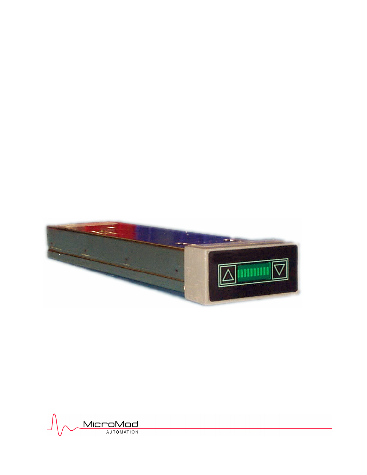
1.1 1750N Output Holder .............................................................................................................1-1
1.2 Catalog Number ......................................................................................................................1-3
2.1 Output Holder Mounting Dimensions......................................................................................2-2
3.1 Generic Output Holder Connection Diagram..........................................................................3-1
3.2 Wiring Diagram ......................................................................................................................3-2
4.1 Opening the Component Gallery ............................................................................................4-1
4.2 Component Gallery ................................................................................................................4-2
4.3 Un-compounding the Compound............................................................................................4-3
4.4 PID_OH Compound ................................................................................................................4-4
4.5 AOUT / AOM block Configuration ........................................................................................... 4-5
4.6 Execution Order ......................................................................................................................4-7
1
Page 4

Output Holder Instructions
CONTENTS
4.7 Opening Component Gallery.................................................................................................. 4-8
4.8 Component Gallery................................................................................................................. 4-9
4.9 Un-compounding the Compound ........................................................................................... 4-10
4.10 PID_OH_MCELL Compound ................................................................................................. 4-11
4.11 AOM block Configuration........................................................................................................ 4-12
4.12 Execution Order...................................................................................................................... 4-14
4.13 Connection Menu ................................................................................................................... 4-15
4.14 Connection Menu ................................................................................................................... 4-15
4.15 IF Block attributes................................................................................................................... 4-16
4.16 Connection to EX block .......................................................................................................... 4-16
4.17 EX Block Connection Input..................................................................................................... 4-17
4.18 EX Block Connection.............................................................................................................. 4-17
4.19 Connection Menu ................................................................................................................... 4-18
4.20 Connection Menu ................................................................................................................... 4-18
4.21 IF Block attributes................................................................................................................... 4-19
4.16 Connection to PID block ......................................................................................................... 4-19
4.23 Connection to PID block ......................................................................................................... 4-20
4.24 PID Block Connection............................................................................................................. 4-20
5.1 Output Holder Front panel ...................................................................................................... 5-1
TABLES
Table
4.1 PID_OH Compound ............................................................................................................... 4-4
4.2 PID_OH_MCELL Compound ................................................................................................ 4-11
5.1 Troubleshooting...................................................................................................................... 5-3
2
Page 5

1.1 OVERVIEW
For safe operation some processes require that valve position be maintained above a
closed position even when a controller might be removed for service or replacement. The
1750N Output Holder is capable of identifying a controller’s output fault and to maintain the
last good value to the field control device for safe operation. When the controllers output
signal to the output holder is restored and again valid the output holder returns control of the
field device to the controller. Under normal operation i.e.; the controllers output is good,
the controllers output is passed through the output holder to the field control device
unaffected.
The 1750N functions as an output holder and a manual loader when connected to a MOD
30ML Controller or Modcell Multiloop Processor.
Output Holder Instructions
PRODUCT DESCRIPTION
SECTION 1
PRODUCT DESCRIPTION
1.2 FEATURES
Output held at last value
Manual control & output display
Feedback circuit for bumpless transfer
Compatible with standard MOD
Figure 1 .1. 1750N Output Holder
1 -1
Page 6

Output Holder Instructions
PRODUCT DESCRIPTION
1.3 RELATED INFORMATION
A general description of the MODCELL and MOD 30ML instruments, mechanical installation
instructions, electrical connection instructions, and communication connection instructions
can be found in the following documents.
• IB-23C600 - Installation for MODCELL Multiloop Processor
• IB-23C601 - Installation for Remote I/O modules (Extended I/O)
• IB-1800R-INS - Installation for MOD 30ML Multiloop Controller
• IB-1800R-M30 - Installation for the MOD 30ML Replacement for MOD 30 Instruments
• IB-23A160 - Instructions for Instrument Communications Network (ICN) Planning
Installation and setup information for the communications link can be found in the following
documents:
• IB-23C001 - Instructions for 1720N Communications Link
• IB-23C003 - Users guide for 17321N ICN Mini Link
• IB-23C004 - Users Guise for 1733N Mini Link/External
Reference information on the data base structure and configuration parameters applicable to
both MODCELL and MOD 30ML instruments can be found in the following documents.
• IB-23G600 - Data Base Reference for Logic I/O and Communication Functions
• IB-23G601 - Data Base Reference for Advanced Control Functions
• IB-23G602 - Data Base Reference for Algorithm, Table and Sequencer Functions
• IB-23H141 - User’s Guide for MODCELL Application Builder Software
General operation and setup information, and reference information on the data base
structures and configuration parameters, which apply only to the MOD 30ML Multiloop
Controller can be found in the following documents.
• IB-1800R-OPR - Operation for MOD 30ML Multiloop Controller
• IB-1800R-APP - Data Base Reference for Display, Alarm, and Built-in I/O Functions
Training labs and tutorial can be found in the following documents:
• IB-VIZAPP-TUT – Training labs for configuring MOD 30ML using ViZapp Software.
• IB-1800R-SCR – Display Guide – Scripting hints, help and examples formed 30ML using
ViZapp Software
• IB-MLOPR-TUT – MOD 30ML Operation Training manual.
1 -2
Page 7

1.4 EXPLANATION OF CATALOG NUMBERS
The products described in this book have catalog numbers that help identify specific features.
In addition, some products are assigned a serial number which can be used to track
manufacturing data.
The catalog number stamped on the product data contains a series of single and multiplecharacter codes. These codes provide specific information concerning various electrical
and/or structural options. Certain code combinations are not allowed, and options and
combinations are subject to change. An example of a typical catalog number is as follows:
Sample Catalog No.
Base Number
Unused
Electrical Code
Power
Options
Unused
Model/Design Level
1750N Z 21 1 0 0 A
Figure 1 .2. Catalog Number
Output Holder Instructions
PRODUCT DESCRIPTION
1.5 ORDERING INFORMATION
NOTE: One analog input is required on the MOD 30ML Controller to accommodate the
feedback circuit for bumpless transfer.
Code No. Description
1750NZ10001A Manual Loader/Output Holder
1 -3
Page 8

Output Holder Instructions
PRODUCT DESCRIPTION
1.6 BASIC HARDWARE
The 1750N, Figure 1-1, is designed for mounting in a panel with a 11.5 inch depth. The
instrument housing contains a 6-point termination facility which accepts all instrument I/O and
power connections.
The 4-20mA output from the MOD 30ML controller is wired in series with the 1750N, and
then to the field. As long as the output from the controller is within the specific limits, the
output holder output is identical to the input (controller output signal). In case of controller
failure resulting in loss of output, the Output Holder retains the last output, thereby enabling
the defective instrument to be replaced without interruption to the process.
A separate output return signal is fed back to the controller, so that when the defective
instrument is replaced the output will automatically match that of the Manual Loader for
bumpless transfer of control. The output holder also provides a discrete output that can be
connected to the controller. This input is the status of the output holder’s presence and can
be used in the controller’s configuration logic.
Use of the Return / Feedback signal (1-5 mA Monitor to controller) and the Output Holder
Sense Discrete signal are optional.
When the 1750N is installed, the output may still be viewed and manipulated when the
controller is removed from the panel for service. Up/Down pushbuttons are provided on the
front panel, allowing direct manipulation of the output by the operator in the event of
controller failure. Output indication is provided by a 10-segment LED bar graph. Screwed
terminal connections are provided for interconnection with the MOD 30ML terminal block.
One Analog Input is required on the MOD 30ML / Modcell for the feedback circuit. Either a
built-in analog input or a plug-in analog input module may be used. A standard configuration
strategy for the MOD 30ML with the feedback circuit is provided in the library of the Visual
Application Designer configuration tool for MOD 30ML / Modcell.
1 -4
Page 9

1.7 SPECIFICATIONS
ANALOG INPUT INPUT/OUTPUT CHARACTERISTICS
Span (0 to 100%)
Lower Limit
Upper Limit
ANALOG OUTPUT (I out)
Span (0 to 100%)
Lower Limit
Upper Limit
CURRENT RETURN (I Return)
Span (0 to 100%)
Lower Limit
Upper Limit
CALIBRATED ACCURACY (% of span)
I out, Run mode
(with respect to analog input)
I out, Hold mode
(with respect to run mode analog
input)
I return, Run mode
(with respect to analog input
span)
I return, Hold mode
(with respect to run mode analog
input span)
INDICATION ACCURACY
1 bar
4 to 20 mA
2.72 mA
21.28 mA
4 to 20 mA
2.72 mA
21.28 mA
1 to 5 mA
0.68 mA
5.32 mA
± 0.5% max
± 1.0% max
± 0.8% max
± 1.2% max
10% ± 2% of
output span
Output Holder Instructions
PRODUCT DESCRIPTION
Analog input resistance
Analog output (I out)
Resistance
Open circuit output voltage
ANALOG OUTPUT LOAD CAPABILITY
Resistance
Capacitance
Inductance
POWER SUPPLY REQUIREMENTS
Normal Operating Range
Allowable Operating range
Allowable Ripple Maximum
Current
ENVIRONMENTAL CHARACTERISTICS
Humidity effect
Static discharge
RFI
Operating temperature
Storage temperature
PHYSICAL CHARACTERISTICS
Width
Depth
Height
Weight.
250 ohms typical
50 kohms min
24V dc max
800 ohms max
10 micro F max
10 H max
23V to 28V dc
20V dc to 28 V dc
1.0 V peak to peak
200 mA max
±0.1% from 25 to
95% relative humidity
at 9°F (32 °C)
<= 10 kV
SAMA standard PMC
33.1.1978 class 1,
Bands A,B, and C
+41°F (+5°C) to
122°F (50°C)
-40°F (-40°C) to
167°F (75°C)
69mm
292mm
35mm
600 GMS
1 -5
Page 10

Output Holder Instructions
PRODUCT DESCRIPTION
1 -6
Page 11

MECHANICAL INSTALLATION
2.1 OVERVIEW
Read these instructions thoroughly before starting installation. Installation personnel should
be qualified technicians..
2.2 Displays and Cleaning
The display is protected by an overlay that can be removed after installation. The face of the
display, while made of scratch-resistant plastic, can be abraded by harsh materials such as
paper towels and industrial wipes. Lens cleaning tissues and soft cloths are suitable for
cleaning displays. Remove dust from the rear of the instrument by removing it from the
instrument housing and spraying exposed surfaces with non-corrosive, non-toxic,
nonflammable inert dusting gas.
2.3 UNPACKING
Unpack and visually inspect the instrument housing and the output holder for
any damage. Save packing materials for any reshipment, or to support any claim of shipment
damage. All damage claims are made against the carrier and are the responsibility of the
customer.
Included in the shipping container is a bag containing mounting brackets and screws, and an
information package. A card containing several copies of a writeable instrument identification
tag is included in the information package. Write required data on the tag and insert it under
the translucent strip at the bottom of the front panel after the controller is installed.
2.4 MOUNTING
The output holder must be installed in an approved enclosure or installed in a means
acceptable to the authority having jurisdiction for electrical installations.
∆WARNING Do not install a MOD 30ML controller in a residential, commercial or light
industrial environment in the European Union.
Select a mounting location where:
Output Holder Instructions
MECHANICAL INSTALLATION
SECTION 2
• There is minimum vibration.
• The ambient temperature is between 32 and 122°F (0 and 50°C) with a relative humidity
of 5-95% RH (noncondensing). The ambient temperature and humidity requirements
apply to the air directly below the output holder.
• The installation allows for free air flow above and below the unit.
• If it is necessary to mount two or more output holders or controllers above each other,
and the room ambient temperature is above 70°F, heat generated by the lower
instruments may raise the ambient of the upper instruments above the 122°F limit. To
assure that operating temperatures are within specified limits, it is recommended that a
fan be installed below the instruments to force air circulation over the instruments in an
upward direction. Air velocity should be at least 100 to 200 feet per minute.
2 -1
Page 12
Output Holder Instructions
MECHANICAL INSTALLATION
• The panel provides rigid support for a fully loaded 5.5-pound (2.5 kg) controller and any
other panel devices.
• Electrical wiring routing and support are planned.
Mount the output holder as follows:
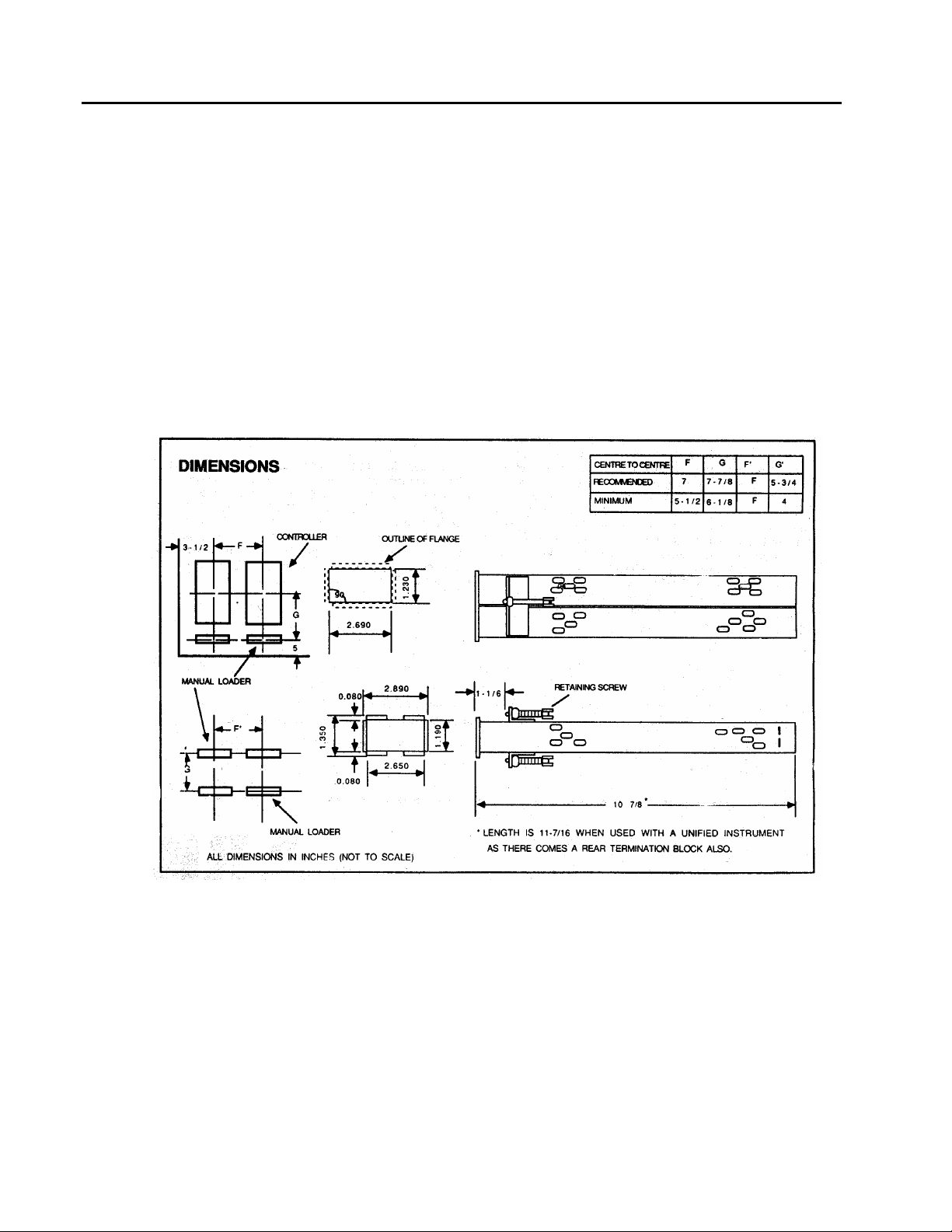
1. Prepare the panel as indicated in Figure 2-1.
2. Slide instrument into panel cutout.
3. Insert brackets into slots in top and bottom of instrument housing.
4. Tighten retaining screws to a torque of 5 inch-pounds (0.6 Nm) or 1-1/2 turns after
contact is made with the back of the panel.
MOUNTING DIMENSIONS
2 -2
Figure 2 .1. Output Holder Mounting Dimensions
Page 13
POWER, GROUNDING, AND I/O CONNECTIONS
3.1 OVERVIEW
Read this section thoroughly before making any connections. Installation personnel should
be qualified technicians. Observe all electrical code requirements and safety standards
applicable to these wiring procedures.
Specific instructions and connection diagrams for the various built-in inputs and outputs are
provided in the following sections. A listing of the applicable electrical specifications is
included in each section.
3.2 CONNECTION GUIDELINES
The wiring connections described in this section are made with the output holder installed in
its operating location and with the power off.
1. The power wire size must be from 14 AWG (1.6 mm) to 18 AWG (1.0 mm) with a 600V, -
20°C +105°C UL, CSA approved rating.
2. The signal wire size can be as small as 22 AWG (0.65 mm). All analog input wiring must
be shielded twisted pairs.
3.3 WIRING AND CONNECTIONS
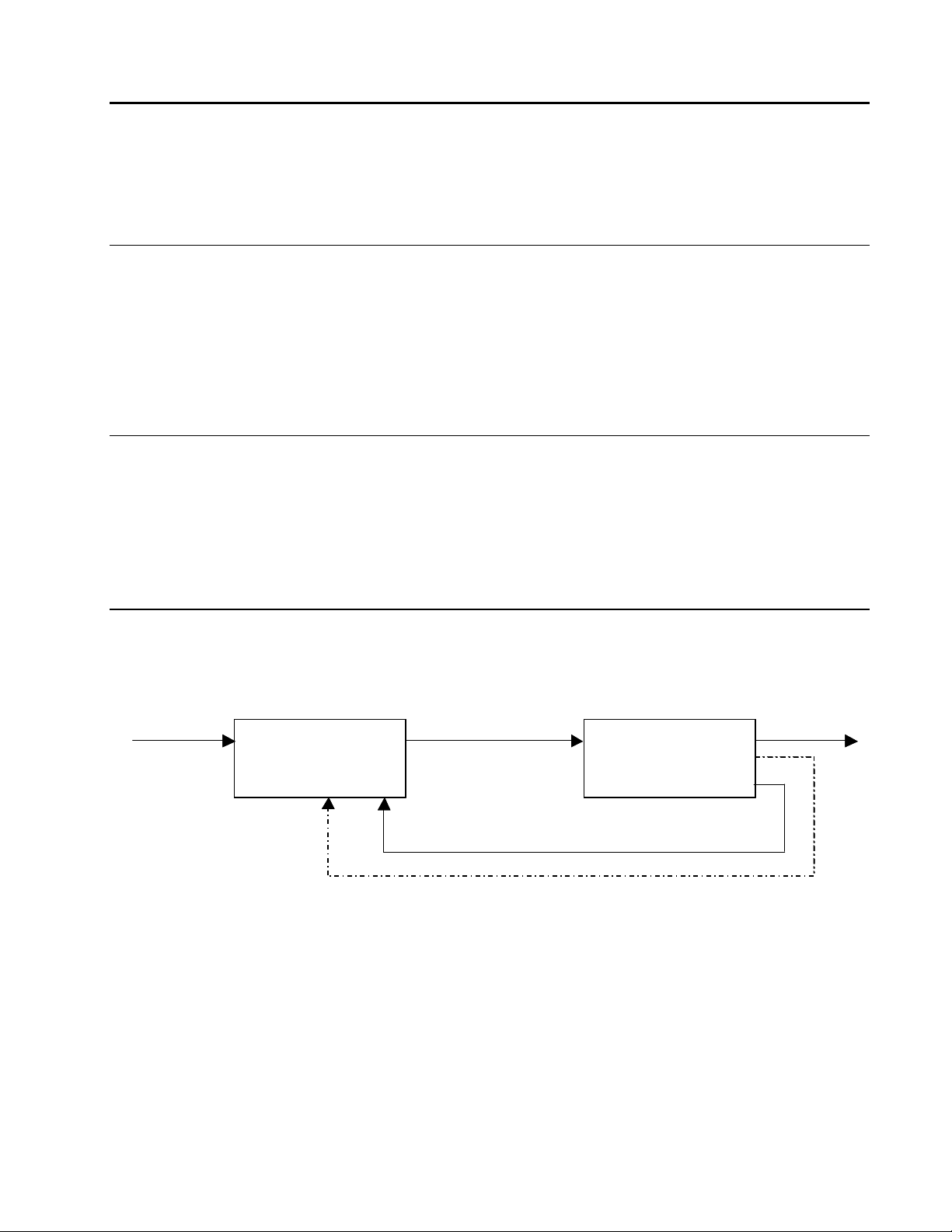
The following figure provides a generic reference as to the signal paths between the
controller and the 1750N Output Holder.
Output Holder Instructions
POWER, GROUNDING, AND I/O CONNECTIONS
SECTION 3
Process Input Controller Output
Process Input Controller Output
Controller
ControllerController
OH Sense to Controller
OH Sense to Controller
Figure 3 .1. Catalog Number
The 1-5 mA monitor to Controller and the OH Sense to Controller connections in the above
scheme are optional. For these connections, two additional inputs are required: The input
types are:
1. 1-5 mA monitor to controller (Return) – one non-two wire input (2002A)
2. OH Sense to the controller – one digital input (2006AZ)
The wiring diagram is shown in the next figure:
1750N
1750N
4-20 mA
4-20 mA
1-5 mA monitor to Controller
1-5 mA monitor to Controller
1750N
Output Holder
Output Holder
Output Holder
4-20 mA to Process
4-20 mA to Process
3 -1
Page 14

Output Holder Instructions
POWER, GROUNDING, AND I/O CONNECTIONS
+
24 VDC
24 VDC
Power
Power
Controller
Controller
+
–
–
1750N Output Holder
1750N Output Holder
+24 VDC from Power Supply1
+24 VDC from Power Supply1
2
Power Supply and Signal Commons
2
Power Supply and Signal Commons
Output
Output
AOUT or 2003A
AOUT or 2003A
4-20mA
4-20mA
O.H. Sense Input
O.H. Sense Input
2006A
2006A
Contact Closure to TCI
Contact Closure to TCI
Output Track Input
Output Track Input
AIN or 2002A
AIN or 2002A
1-5mA to OPTI
1-5mA to OPTI
+
+
–
–
+
+
–
–
+
+
–
–
3
4-20mA Output from Controller
3
4-20mA Output from Controller
4
1-5mA Monitor to Controller
4
1-5mA Monitor to Controller
5
O.H. Sense to Controller (internally tied to Common)
5
O.H. Sense to Controller (internally tied to Common)
6
4-20mA Output to Field Device
6
4-20mA Output to Field Device
Figure 3 .2. Wiring diagram
The exact wire connections for a particular MOD 30ML Controller or Modcell depends on how
many outputs are being held and where the Sense and Return I/O points for each loop are
located on the controller. For example, if you are using the MOD 30ML controller and if you
are not using the built-in input 2, it may be set up for 1-5 mA non-two wire and used to bring
in the Return signal.
In all cases, the Sense signal will require the installation of a 2006AZ digital input module. It
is also your preference to use or not use the SENSE signal from the output holder. Refer to
chapter 4 for different configuration options with respect to the Sense signal.
3.4 CONNECTING OTHER CONTROLLERS
The output holder can also be used with controllers other than MOD 30ML and Modcell.
Follow the same scheme as given in Figure 3.2.
Use of the Return / Feedback signal (1-5 mA Monitor to controller) and the Output Holder
Sense Discrete signal are optional.
Field Device
Field Device
3 -2
Page 15

SECTION 4
CONFIGURATION
4.1 OVERVIEW
The Compound Gallery in the ViZApp (Visual Application Builder) software includes a
compound called PID_OH. This section explains how to configure MOD 30ML or Modcell
using this compound for use with the Output Holder. The purpose of this compound is to
cause the control loop to synchronize its output holder before turning its field output on. This
will in turn cause a bump less transfer. This happens only when the controller first initializes
at power up.
4.2 LOADING THE COMPOUND FOR MOD 30ML
The PID_OH compound has a fully functional PID, with I/O, Display, Tuning List and also the
logic for bumpless transfer of output.
Output Holder Instructions
CONFIGURATION
If you already have your PID configured, you can delete the blocks that are not required from
this compound after loading.
1. Launch the ViZapp Software and open your workspace, project and the instrument
database.
2. The PID_OH compound can only be loaded inside a loop compound. Open the loop
compound where you want to load the PID_OH compound.
3. Select Project – Gallery – Component Gallery from the menu bar as shown in the
figure below:
Figure
4 .1. Opening the Component Gallery
4 -1
Page 16

Output Holder Instructions
CONFIGURATION
4. The Component Gallery dialog will be displayed as shown in the next figure. Select
the Compounds tab and click on the PID_OH compound from the list of compounds
as shown and then click on the Export button.
Figure 4 .2. Component Gallery
The Compound will be placed in your database. The function blocks are located
inside this compound. You can un-compound the loaded PID_OH compound. With
the loaded compound selected, select Objects – Uncompound from the menu bar.
Refer to the next figure:
4 -2
Page 17

Output Holder Instructions
CONFIGURATION
Figure 4 .3. Un-compounding the compound
After you un-compounded the PID_OH compound, it will be displayed as shown in
the next figure.
4 -3
Page 18

Output Holder Instructions
CONFIGURATION
Figure 4 .4. PID_OH Compound
The compound has the following function blocks:
Block Name Type Description
pid PID The PID control block
disp DISP Display for the PID
TuningList TL Tuning list for the PID
PV AIN Built-in input used for PV
Pv_i VCI Signal conditioning for the AIN
op_ao AOUT Built-in analog output block
RETURN AIN Built-in input used to get the feedback from the output
holder. Configured as 1-5 mA
RETURNF1 VCI Signal conditioning for the AIN. Configured as 0 – 100
%
SENSE DIM Digital input to sense the presence of the output holder
SENSEF DI Signal Conditioning for the DIM block
OP_T_LGC EX Logic for bumpless transfer
Table 4-1. PID_OH Compound
There is also a Notes block that has text that explains how to use this compound as
shown in the Figure 4-4. This compound can be used as it is.
You may need to make the following changes depending on your process
application:
4 -4
Page 19

Output Holder Instructions
CONFIGURATION
1. The compound uses an AIN (Built-in Analog Input) block configured as current input (420mA) and a VCI block for ranging it to 0-100 engineering units linear. It also has a builtin AOUT block. You can substitute different type of input or module, conditioning and
analog output blocks
2. The compound also has preconfigured PID, Display and Tuning List blocks, which you
can substitute with your existing blocks in your database.
3. The compound uses a built-in input (RETURN) and a VCI conditioning (RETURNF1)
blocks for reading the feedback from the output holder. This is the feedback of the output
value from the output holder sent to the field. This value is tied to the output track input
(OPTI) of the PID block so that the PID block tracks this value upon start up. This is how
a bump less transfer of output value is achieved. If you do not need bumpless transfer of
output, you can optionally remove these two blocks.
4. The AOUT block is configured as shown below for Restart/Failsafe conditions:
Figure 4 .5. AOUT / AOM block configuration
The Restart output is configured as Preset with a value of –25. The reason for this is
when a faulty controller is replaced with a new or a repaired one, a momentary zero
output from the controller at startup will be seen as a valid input by the output holder and
it will switch to zero values. To avoid this a momentary faulty value (negative 25) is
introduced at the startup and then the PID block’s output will override this value.
5. The compound uses a Digital input block (DIM - SENSE) and a digital conditioning block
(DI – SENSEF) to sense the presence of the output holder. This discrete signal along
4 -5
Page 20

Output Holder Instructions
CONFIGURATION
with the RUNINIT signal from the Interface (IF) block is used in the EX block to enable
output tracking in the PID block. The logic configured in the EX block OP_T_LGC is as
shown below:
In the above expression && is the logical AND function. The RUNINIT signal from the IF
block goes high momentarily upon controller startup. If the output holder is not present,
the PID block does not have to switch its output to track mode upon start up.
If bumpless transfer of output is not an issue (refer to step 3 above) in your application,
then you can remove these blocks also.
6. Connect the RUNINIT attribute from the IF block to the RUNINIT User Input of the EX
(OP_T_LGC ) block. Refer to the section 2-3-1 for the procedure.
7. The following relative EXECUTION ORDER MUST BE MAINTAINED!
If using other I/O for Sense and Return be sure to maintain same relative execution
order. To set the execution order, select Objects – Set Execution Order – List Mode from
the ViZapp menu bar to display the Execution order table as shown in the next figure:
SENSE && RUNINIT
PV
pv_I
RETURN
RETURNF1
SENSE
SENSF
OP_T_LGC
Pid
op_ao
Disp
TuneList
4 -6
Page 21

Output Holder Instructions
CONFIGURATION
Figure 4 .6. Execution Order
If you are using the MOD30 Conversion Style Instrument, change Input Signal Range
of PV to 1 to 5 Volts and RETURN to 0.25 to 1.25 Volts.
8. Optionally you can include the output holder feedback (RETURN) only in the
configuration and not the presence of the output holder (SENSE). In this case you do not
need the discrete input module in the controller. The configuration will not have the
SENSE (DIM), SENSEF (DI) and the OP_T_LGC (EX) blocks. You can delete these
blocks from the loaded compound. You would still need to connect a track command
input to the PID block. This will again be the RUNINIT signal from the IF block connected
to the TCI attribute of the PID block ensuring bumpless transfer of the output value. Refer
to the section 4.4 Connection RUNINIT from the IF block, Option 2 for the procedure.
9. Compile and download your database to the controller.
4 -7
Page 22

Output Holder Instructions
CONFIGURATION
4.3 LOADING THE COMPOUND FOR MODCELL
The PID_OH compound has a fully functional PID, with I/O and also the logic for bumpless
transfer of output.
If you already have your PID configured, you can delete the blocks that are not required from
this compound after loading.
1. Launch the ViZapp Software and open your workspace, project and the instrument
database.
2. The PID_OH1 compound can only be loaded inside a loop compound. Open the loop
compound where you want to load the PID_OH compound.
3. Select Project – Gallery – Component Gallery from the menu bar as shown in the
figure below:
4 -8
Figure 4 .7. Opening the Component Gallery
4. The Component Gallery dialog will be displayed as shown in the next figure. Select the
Compounds tab and click on the PID_OH_MCELL compound from the list of compounds
as shown and then click on the Export button.
Page 23

Output Holder Instructions
CONFIGURATION
Figure 4 .8. Component Gallery
The Compound will be placed in your database. The function blocks are located inside
this compound. You can un-compound the loaded PID_OH compound. With the loaded
compound selected, select Objects – Uncompound from the menu bar. Refer to the
next figure:
4 -9
Page 24

Output Holder Instructions
CONFIGURATION
4 -10
Figure 4 .9. Un-compounding the compound
After you un-compounded the PID_OH compound, it will be displayed as shown in the
next figure.
Page 25

Output Holder Instructions
CONFIGURATION
Figure 4 .10. PID_OH1 Compound
The compound has the following function blocks:
Block Name Type Description
pid PID The PID control block
PV VCIM Voltage/Current Input block used for PV
Pv_i VCI Voltage/Current Signal conditioning for the AIN
op_ao AOM Analog output block
RETURN VCIM Voltage/Current input used to get the feedback from
the output holder. Configured as 1-5 mA
RETURNF1 VCI Signal conditioning for the AIN. Configured as 0 – 100
%
SENSE DIM Digital input to sense the presence of the output holder
SENSEF DI Signal Conditioning for the DIM block
OP_T_LGC EX Logic for bumpless transfer
Table 4-1. PID_OH Compound
There is also a Notes block that has text that explains how to use this compound as
shown in the Figure 4-4. This compound can be used as it is.
You may need to make the following changes depending on your process application:
1. The compound uses a Voltage/Current Input module (VCIM) block configured as current
input (4-20mA) and a VCI block for ranging it to 0-100 engineering units linear. It also has
an analog output module (AOM) block. You can substitute different type of input or
module, conditioning and analog output blocks
2. The compound also has preconfigured PID block, which you can substitute with your
existing PID block in your database.
4 -11
Page 26

Output Holder Instructions
CONFIGURATION
3. The compound uses a VCIM (RETURN) and a VCI conditioning (RETURNF1) blocks for
reading the feedback from the output holder. This is the feedback of the output value
from the output holder sent to the field. This value is tied to the output track input (OPTI)
of the PID block so that the PID block tracks this value upon start up. This is how a bump
less transfer of output value is achieved. If you do not need bumpless transfer of output,
you can optionally remove these two blocks.
4. The AOM block is configured as shown below for Restart/Failsafe conditions:
4 -12
Figure 4 .11. PID_OH1 Compound
The Restart output is configured as Preset with a value of –25. The reason for this is
when a faulty controller is replaced with a new or a repaired one, a momentary zero
output from the controller at startup will be seen as a valid input by the output holder and
Page 27

Output Holder Instructions
CONFIGURATION
it will switch to zero values. To avoid this a momentary faulty value (negative 25) is
introduced at the startup and then the PID block’s output will override this value.
5. The compound uses a Digital input block (DIM - SENSE) and a digital conditioning block
(DI – SENSEF) to sense the presence of the output holder. This discrete signal along
with the RUNINIT signal from the Interface (IF) block is used in the EX block to enable
output tracking in the PID block. The logic configured in the EX block OP_T_LGC is as
shown below:
SENSE && RUNINIT
In the above expression && is the logical AND function. The RUNINIT signal from the IF
block goes high momentarily upon controller startup. If the output holder is not present,
the PID block does not have to switch its output to track mode upon start up.
If bumpless transfer of output is not an issue (refer to step 3 above) in your application,
then you can remove these blocks also.
6. Connect the RUNINIT attribute from the IF block to the RUNINIT User Input of the EX
(OP_T_LGC ) block. Refer to the section 2-3-1 for the procedure.
7. The following relative EXECUTION ORDER MUST BE MAINTAINED!
PV
pv_I
RETURN
RETURNF1
SENSE
SENSF
OP_T_LGC
Pid
op_ao
If using other I/O for Sense and Return be sure to maintain same relative execution
order. To set the execution order, select Objects – Set Execution Order – List Mode from
the ViZapp menu bar to display the Execution order table as shown in the next figure:
4 -13
Page 28

Output Holder Instructions
CONFIGURATION
Figure 4 .12. Execution Order
8. Optionally you can also include the feedback (RETURN) only in the configuration and not
the presence of the output holder (SENSE). In this case you do not need the discrete
input module in the controller. The configuration will not have the SENSE (DIM),
SENSEF (DI) and the OP_T_LGC (EX) blocks. You can delete these blocks from the
loaded compound. You would still need to connect a track command input to the PID
block. This will again be the RUNINIT signal from the IF block connected to the TCI
attribute of the PID block ensuring bumpless transfer of the output value. Refer to the
section 4.4 Connection RUNINIT from the IF block, Option 2 for the procedure.
9. Compile and download your database to the controller.
4 -14
Page 29

4.4 CONNECTING RUNINIT FROM THE IF BLOCK
Option1: When using both RETURN and SENSE signals from the output holder:
To connect the RUNNIT attribute from the IF block, refer to the section select the
connector (multi segment or right angle) from the Algorithms Window and then click on a
blank area of the instrument document near the EX block.
Output Holder Instructions
CONFIGURATION
Figure 4 .13. Connection Menu
Select Compound External from the menu as shown above.
Figure 4 .14. Connection Menu
Select the IF block from the menu and then click on the OK button.
4 -15
Page 30

Output Holder Instructions
CONFIGURATION
Figure 4 .15. IF block attributes
Select the RUNINIT attribute from the list and click on the OK button. Drag the
connection line to the EX block and click on it.
Figure 4 .16. Connection to EX block
4 -16
Page 31

Output Holder Instructions
CONFIGURATION
Figure 4 .17. EX block Connection Input
Select the user Input RUNINIT and click on OK. The connection is complete now. See
the next figure:
Figure 4 .18. EX block connection
4 -17
Page 32

Output Holder Instructions
CONFIGURATION
Option2: When using only the RETURN signal from the output holder:
To connect the RUNNIT attribute from the IF block, refer to the section select the
connector (multi segment or right angle) from the Algorithms Window and then click on a
blank area of the instrument document near the EX block.
Select Compound External from the menu as shown above.
Figure 4 .19. Connection Menu
4 -18
Figure 4 .20. Connection Menu
Select the IF block from the menu and then click on the OK button.
Page 33

Output Holder Instructions
CONFIGURATION
Figure 4 .21. IF block attributes
Select the RUNINIT attribute from the list and click on the OK button. Drag the
connection line to the PID block and click on it.
Figure 4 .22. Connection to PID block
4 -19
Page 34

Output Holder Instructions
CONFIGURATION
Figure 4 .23. Connection to PID block
Select the user Input TCI and click on OK. The connection is complete now. See the next
figure:
Figure 4 .24. PID block connection
4 -20
Page 35

4.5 THEORY OF OPERATION
When the instrument powers up the process value is read first followed by the RETURN and
SENSE inputs. The expression block OP_T_LGC is executed next with a result that becomes
true when both the SENSE and RUNINIT inputs are true. The SENSE input will always be
true when an output holder is present. The RUNINIT input is true only for a moment when the
instrument powers up. The output of the EX block is connected t the track command input
(TCI) of the PID block. For this brief moment that the EX block’s output is true, the PID
block’s output will track the RETURN input connected to its track source (OPTI). This is the
feedback from the output holder of what it sends to the field. The PID block uses this value
until told to change based on automatic or manual manipulation. This PID output value is
sent to the output block causing the output block’s output current to be equal to that of the
output holder output.
The return input block is set to receive 1 to 5 mA. Its input conditioning block converts this
into 0 to 100 as engineering units that correspond to the PID block output.
The initial value of the SENSE input block and its corresponding input conditioning block are
set to false. As well the output block’s initial value is also set to zero. This permits the output
holder card to maintain the control of the device until the controller’s output is synchronized to
the output holder’s output.
Output Holder Instructions
CONFIGURATION
4 -21
Page 36

5.1 OVERVIEW
This chapter provides operating instruction and maintenance information for the output holder
instrument.
5.2 OPERATION
The output holder can display the controller’s output in a 10 segment horizontal bar graph. It
has 2 keys (UP and DOWN) that enable manual output adjustment in the absence of the
main controller.
Operator activity available during runtime:
Monitor the output only as long as the main controller whose output is sending a valid
output to the output holder
Monitor and manipulate the output using the UP and the DOWN keys when the output
holder is not receiving a healthy value from the controller.
5.2.1 FRONT PANEL
The front panel has the UP and DOWN keys and a 10 segment bar graph as shown below::
Output Holder Instructions
OPERATION AND MAINTAINANCE
SECTION 5
OPERATION AND MAINTAINANCE
Figure 5 .1. Output Holder front panel
5 -1
Page 37

Output Holder Instructions
OPERATION AND MAINTAINANCE
5.2.2 CONTROL KEYS
The operator control keys are:
5.2.3 BAR DISPLAY
The 10 segment horizontal bar graph provides visual indication of the output holder’s output.
Each segment represents up to 10 % of the output. The segment’s light intensity varies as
the value changes from minimum to maximum of the value it represents.
Used to ramp up the output holder’s output when the controller
output is not valid.
Used to ramp down the output holder’s output when the
controller is not valid.
5.2.2 UP /DOWN KEY OPERATION
Press the UP key or DOWN key to manipulate the output. Pressing and holding the key will
make the rate of ramping faster.
5 -2
Page 38

5.3 TROUBLESHOOTING AND MAINTAINANCE
Indication
The bar graph does not
show any indication
The bar graph does not
show any indication and
pressing the UP key does
not change the value
Possible Cause Solution
The output is zero percent.
This is because each
segment in the bar graph
represents 10 % of the value.
Each segment has varying
light intensity to represent
any intermediate value.
This could be because there
is no load at the output of the
output holder or the wires are
cut or there is loose
connection at the terminals.
Faulty instrument
Output Holder Instructions
OPERATION AND MAINTAINANCE
Check the wiring at the
terminals 6 and 2 at the
back or the load (Current
to pressure converter or
the final control element).
Call customer service.
5 -3
Page 39

Output Holder Instructions
OPERATION AND MAINTAINANCE
Notes:
5 -4
Page 40

Page 41

The Company’s policy is one of continuous product improvement and the right
is reserved to modify the information contained herein without notice, or to
make engineering refinements that may not be reflected in this bulletin.
Micromod Automation assumes no responsibility for errors that may appear in
this manual.
© 2004 MicroMod Automation, Inc. Printed in USA
IB-1750N-INS, Issue 2 12/2004
MicroMod Automation, Inc.
75 Town Centre Drive
Rochester, NY USA 14623
Tel. 585-321 9200
Fax 585-321 9291
www.micromodautomation.com
 Loading...