

Page 1
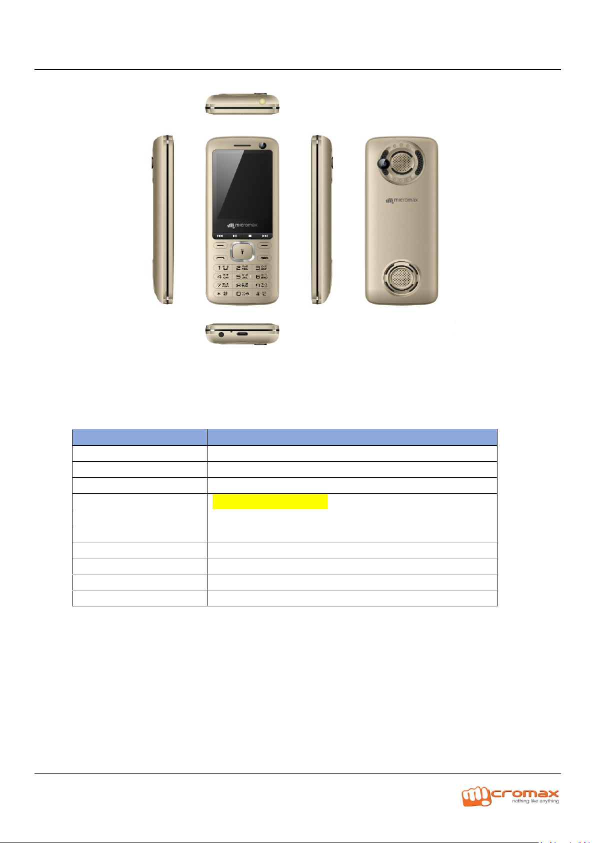
Particular
Remarks
Key Matrix For Flashing
NA
Chipset
SC6531E
Android Version
NA
Frequency
GSM:850/900/1800/1900
Network Mode
Dual SIM:GSM
ROM
32Mb
RAM
32Mb
Internal SD Card memory
NA
Expandable Memory
32 GB
Factory mode code
*#629#
Model X771 L3 Service Manual
2. CAUTIONS
1. Technical Specifications :
Please fill below information in Remarks, Below given remarks are for reference only
I. Flashing & Servicing must be undertaken by qualified personnel only.
II. Ensure all work is carried out at an anti-static workstation and that an anti-static wrist strap is worn.
III. Use only approved Tools & components as specified in the parts list.
Page 2
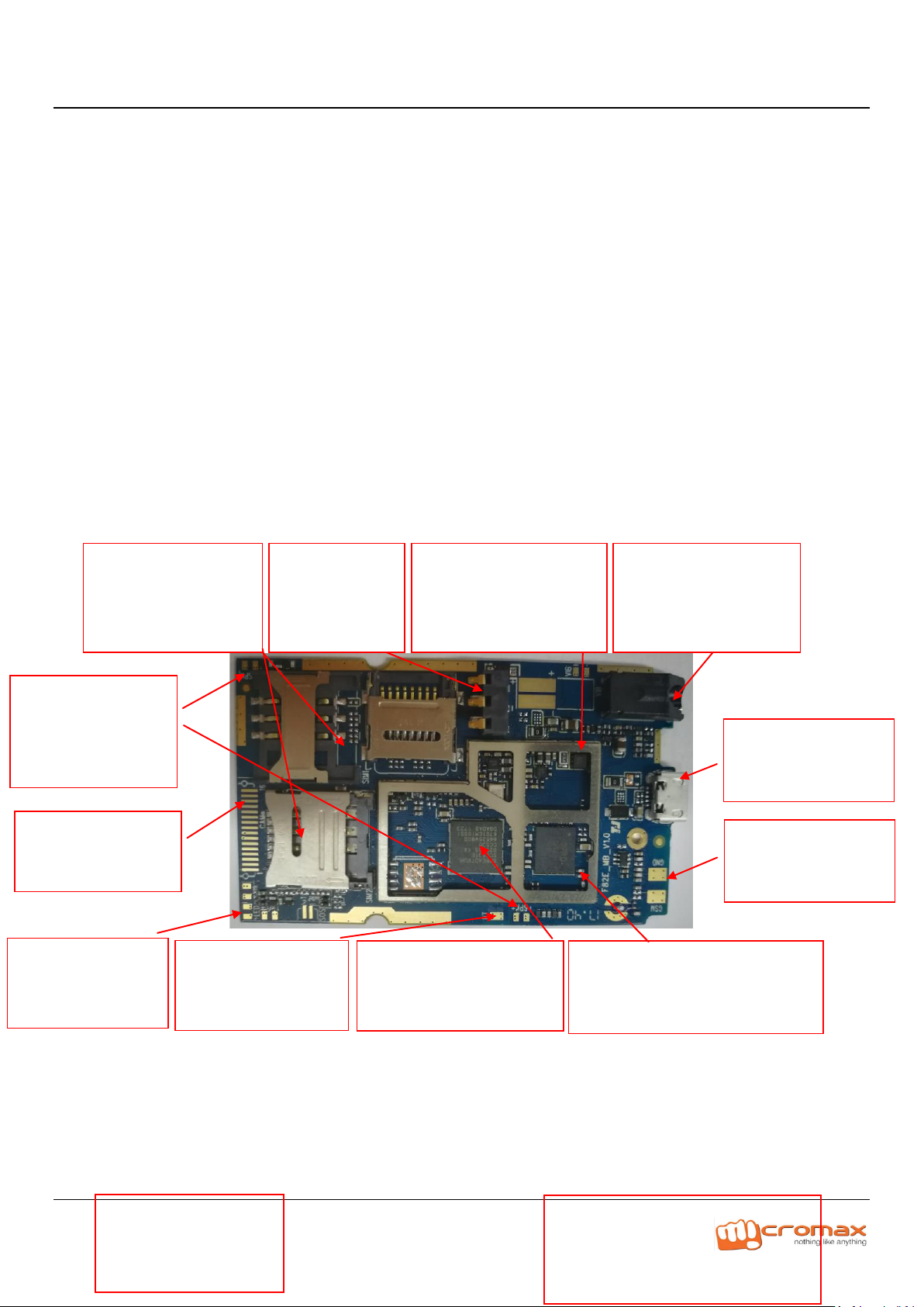
J400 earphone connector
Failure caused by damage:
Earphone failure, FM failure
J100 antenna bonding pad
Failure caused by damage:
Weak BT signal
J800/J802 SIM1/SIM2 card
socket
Failure caused by damage:
Failure to identify GSM/
U600 charge IC
Failure caused by damage:
Failure to No indication during
charging
ANT1/ANT2 GSM PAD
Failure caused by
damage: GSM failure
U0101 GSM PA chip Failure caused
by damage:RF failure
U300 communication processor
Failure caused by damage:
Power-on failure
SPK speaker
Failure caused by
damage: No sound from
speaker
CAM pad
Failure caused by
damage:CAM failure
J602 Bat connector
Failure caused by
damage:
Power-on failure
LCD LCD pad
Failure caused by damage:
Display backlight failure
D700/D701/D702/D703/D704/D705
Keypad backlight
Failure caused by damage:
Keypad backlight failure
LED pad Failure caused
by damage: LED torch
failure
USB Connector Failure
caused by damage: No
port, no charging
Model X771 L3 Service Manual
IV. Ensure all components, modules, screws, and insulators are correctly re-fitted after servicing and
alignment
V. Ensure all cables and wires are repositioned correctly if Handset disassembled
VI. Electrostatic discharge can easily damage the sensitive components of electronic products. Therefore,
Service Centre must adhere the precautions which mentioned above.
Basic Structure of the Mobile Phone
PCBA Diagrams of A81 Mainboard
Page 3
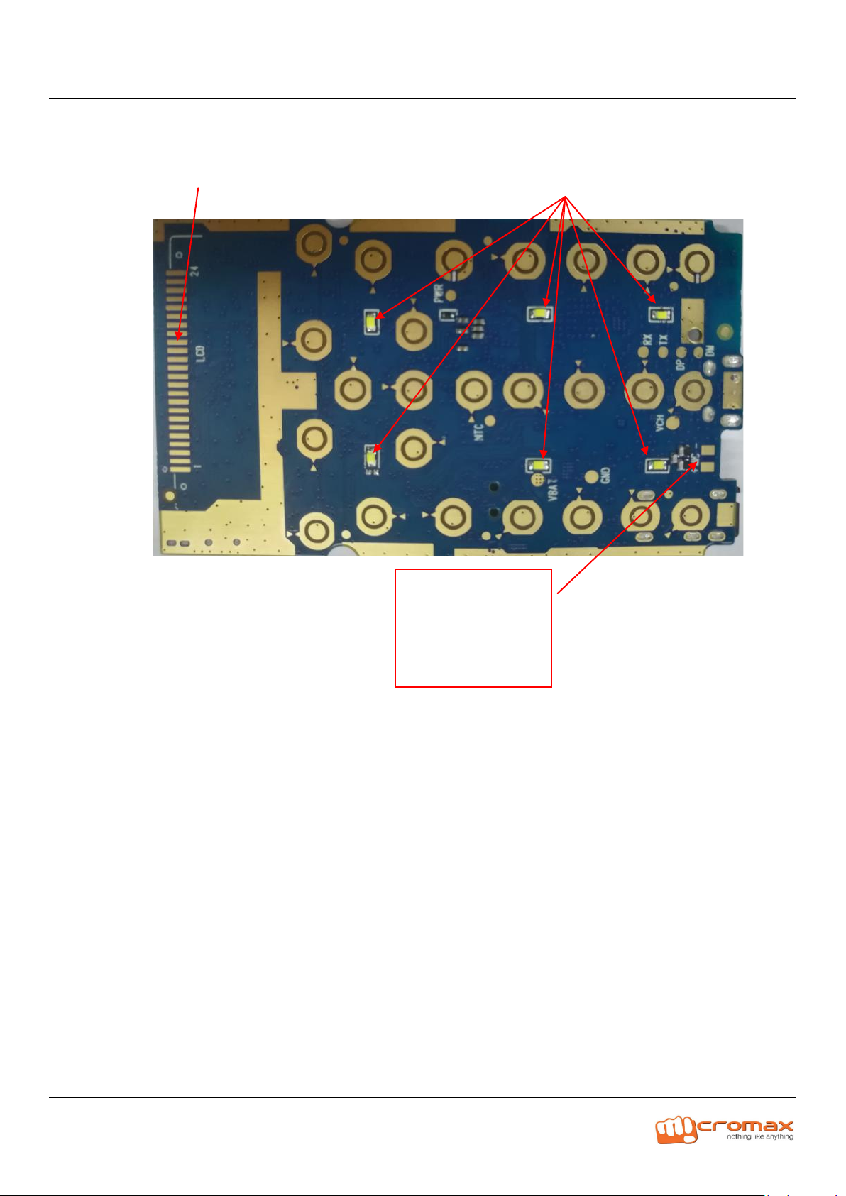
GOLD_MIC,MIC pad
Failure caused by
damage:
No sound when voice is
transmitted via local MIC;
Model X771 L3 Service Manual
3. L3 Level trouble shooting
Please add trouble shooting/ Repairing steps against below given symptoms
Images must paste against every suggested troubleshooting hint
1) Doesn’t Power On
Page 4
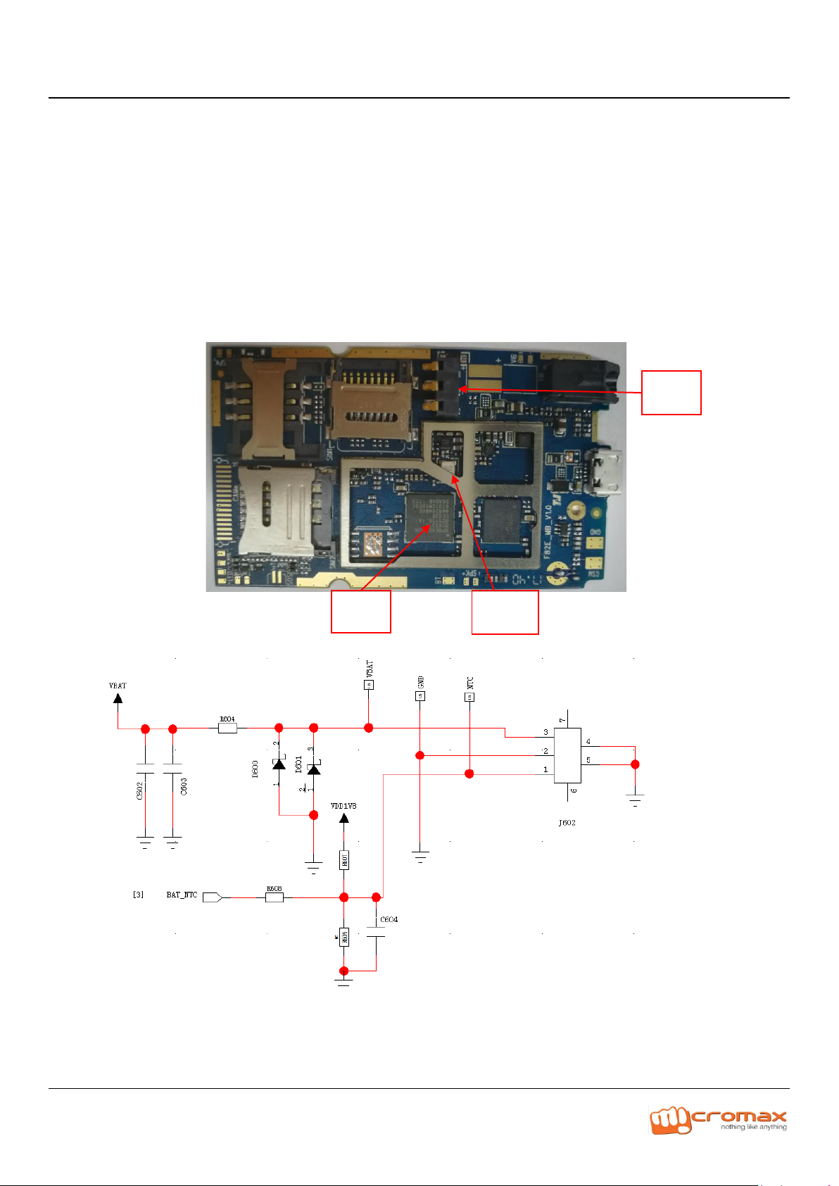
Y200
U300
J602
Model X771 L3 Service Manual
Solution
A- There is no current when the Power Key is pressed; check J602 to see if there is false soldering,
pseudo soldering, if yes, Carry out Resoldering or replacement;
B- When the Power Key is pressed, and the current stays within 10~15mA, if yes, Upgrade the
software version;
C- There is current when the Power Key is pressed; the current changes to 0~5mA when the key is
loosened, if yes, The problem is caused by pseudo soldering or damage of 26M crustal(Y200);
carry out repair soldering or replacement of the crystal. Or, it is caused by pseudo soldering or
damage of CPU;
D- There is heavy current when the Power Key is pressed, if yes, Find the hot point, and replace the
corresponding material CPU(U300) are damaged in most cases.
2) Restart / Hang
Solution: Refer same to Power failure issue.
3) LCD
Page 5
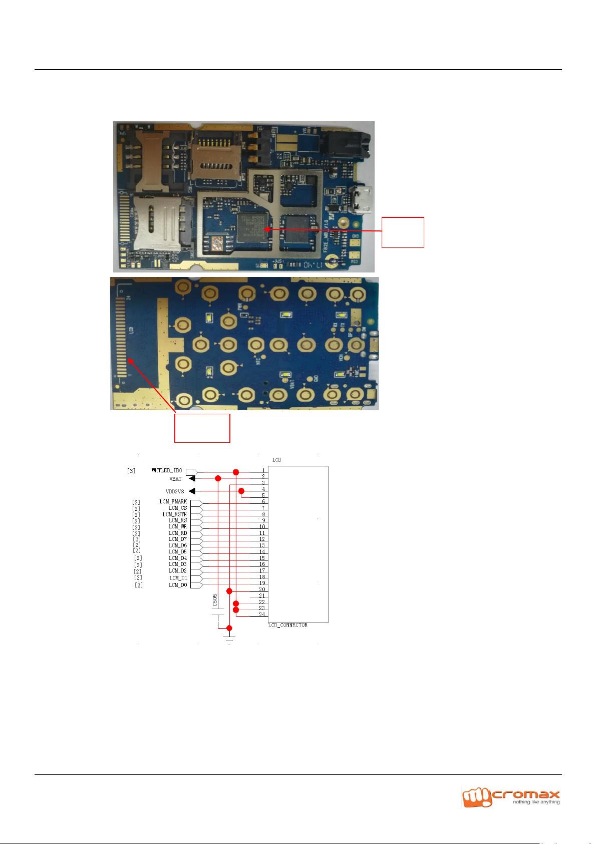
LCD
U300
Model X771 L3 Service Manual
Solution:
A- Exchange the front shell to judge if the LCD itself is abnormal, if yes, Replace the LCD;
B- Replace the CPU(U300)
4) Touchpad
NA
5) Proximity Sensor
NA
6) Accelerometer
NA
7) Keypad
Page 6
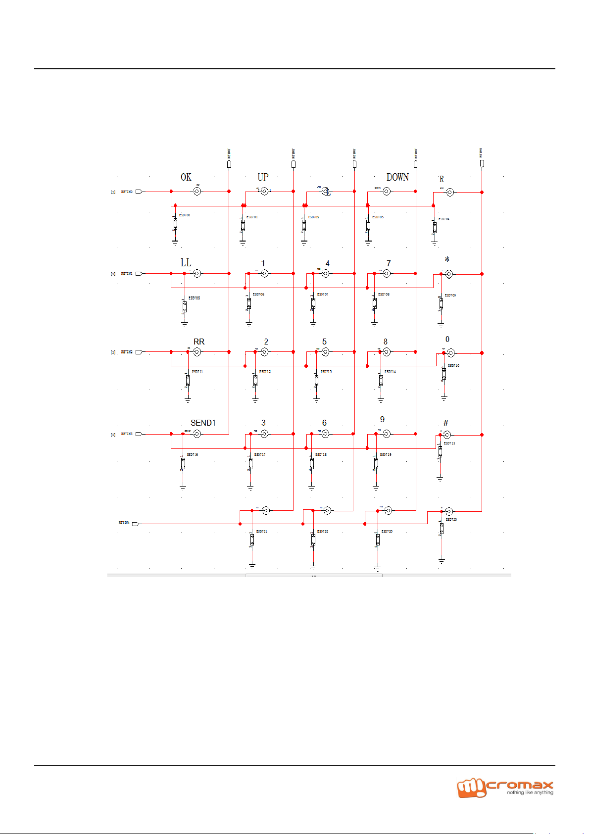
Model X771 L3 Service Manual
Solution:
A- The common breakdown mainly does not work for the pressed key, the pressed key expiration. May defer to the
schematic diagram to examine whether by short circuit, abruption phenomenon. Or examined whether
underneath Dome has the foreign matter.
8) Charging
Solution:
A- Check if the charging IC U600 is abnormal, if yes, Carry out repair soldering or replacement;
B- Check if the resistors R601 are abnormal, if yes, Carry out repair soldering or replacement;
Page 7

U300
R601
U600
Model X771 L3 Service Manual
C- Replace the U300
9) USB
Solution:
Page 8

J603
U600
R601
U300
Model X771 L3 Service Manual
A- Check if the connector J603 is damaged or pseudo soldering, if yes, Carry out repair soldering or
replacement of the material
B- Check if the charging IC U600/R601 is abnormally soldered or damaged, if yes, Carry out repair
soldering or replacement.
C- Replace U300
10) Main Camera
Page 9

J500
Model X771 L3 Service Manual
Solution:
A- Check if the camera is properly installed, if yes, Reinstall it;
B- Exchange the camera to see if the problem is solved, if yes, The problem is caused by the
camera itself; replace it;
11) Front Camera
NA
Page 10

RF_
ANT
Model X771 L3 Service Manual
12) Flash Light
NA
13) Vibrator
NA
14) Network
Solution:
A- Test the conduction power to see if it normal; if normal, test the circuit between the RF test
pad and the antenna to see if it is normal; or else, see the analysis of“abnormality of
conduction power”.
B- Test the circuit between the RF test pad and the antenna to see if it is normal are shown in the
following chart;
C- Check if the contact between the antenna and the antenna spring clip is normal. Deformation
of the antenna spring clip, which will affect coupling of RF signal, further resulting in low
coupling power. This problem can be solved by replacing the damaged component.
D- Damage of component material in the RF circuit, which can be solved by replacing the
material;
E- Pseudo soldering of components, which can be solved by repair soldering;
F- Direction error or position shift of components due to surface mounting, which can be solved
by Properly soldering the components;
G- Power abnormality caused by abnormal calibration, which can be solved by using proper
Calibration software configuration and instrument.
The repairman can check item by item according to the signal trend in the diagram, so as to
Determine the failure position.
Page 11

BT
PAD
Model X771 L3 Service Manual
15) 3G-LTE not working
NA
16) WI-FI
NA
17) Bluetooth
Solution:
A- Exchange the BT ANT to see if the problem is solved, if yes, It is the problem of the BT ANT
B- The repairman can check item by item according to the signal trend in the diagram, so as to Determine
the failure position.
Page 12

Earphone
jack
Model X771 L3 Service Manual
18) FM / Radio
Solution:
A- Exchange the earphone to see if the problem is solved, if yes, It is the problem of the earphone.
B- Exchange the earphone jack to see if the problem is solved, if yes, It is the problem of the earphone
jack.
C- The repairman can check item by item according to the signal trend in the diagram, so as to Determine
the failure position.
Page 13

Earphone
jack
U300
L402
L401
Model X771 L3 Service Manual
19) Heating
Please refer same with Power-on failure.
20) Ear Phone
Solution:
A- Visually inspect the earphone jack to see if there is any abnormality, if yes, Replace the earphone jack
B- Check if L401,L402have pseudo soldering, if yes, Carry out repair soldering;
C- Replace U300
21) Outgoing Audio / MIC
Solution:
A- Exchange the MIC to see if the problem is solved, if yes, It is the problem of the MIC
B- Pseudo soldering of C6009,C6017,R6003,R6000,R6007 and R6008 on the PCBA;
C- Problem of U1000
Page 14

R402
R401
R400
U300
R403
C400
C404
Model X771 L3 Service Manual
22) Incoming Audio / Earpiece
Solution:
A- Visually inspect the earphone jack to see if it is abnormal, if yes, Replace the earphone jack;
B- Check if L401 L402 L400 have pseudo soldering, if yes, Carry out repair soldering;
Page 15

Earphone
jack
L400
U300
L402
L403
L401
U400
U401
Model X771 L3 Service Manual
23) Speaker
Solution:
A- Exchange the speaker to see if the problem is solved, if yes, It is the problem of the speaker;
B- Check if U400,U401 have pseudo soldering or damage, if yes, Replace U400/U401
C- Replace U300
Page 16

U300
J801
Model X771 L3 Service Manual
24) SD Card
Solution
A- Exchange the J801 to see if the problem is solved, if yes, It is the problem of the TF socket;
B- Replace U300
Page 17

U300
J800
J802
Model X771 L3 Service Manual
25) SIM Card
Solution
C- Exchange the J800 or J802 to see if the problem is solved, if yes, It is the problem of the sim socket;
D- Replace U300
Page 18

Model X771 L3 Service Manual
Thanks
For any Query or suggestion, Please write to tech.help@micromaxinfo.com
 Loading...