

Page 1
10. Fill a flask or beaker with liquid to be pumped through the system.
Place the fill tubing in the reservoir and affix using a tubing clip.
11. Software Configuration: Using the touchscreen controller,
navigate to the Configuration S creen, then sele ct Hardware, then
select Syringe and set the volume of the syringe(s). Go back one
menu and selec t Valve to set the valve configuration. (Section 4.3)
®
Microlab® 600 Quick Start Guide
For additional instructions, please refer to the sections in the
Basic Manua l referenced by each step.
Note: All dual sy ringe pumps w ill be configur ed as a Diluter.
1. Unpack the instrum ent and verif y you have the proper
components for your unit. (S ec tion 2 .1)
2. Sele ct a clean, dry and level location to install the Microlab 600.
(Section 2. 2)
3. Place the syringe drive unit in the de sired location. Place the
controller on top of the pump and connect the pump and
controller with the Ethernet Cable.
6. Syringe Installation: Press and hold the Prime but ton. After
three seconds, the sy ringe drive will b egin moving down to
allow for installatio n of the syringe(s). Release the Pr ime button
when the syringe(s) are approximately 50% from the bot tom of
stroke. Install the syringe(s). (Section 2.4.2)
4. Plug the power supply (P/N 61092-01) into the back of the syringe
drive unit. Then plug the power cord into the power sup ply and then
into a wall outlet. The pump will automatically tur n on. It will take
approximately 30 sec onds for the controlle r to boot up completely.
5. Valve Installation: The Microlab 60 0 comes with the valve (s)
already install ed. For a Single Syringe instrument, sk ip to step 6.
For a Dual Syring e instrument, the valve s come with the cross
tube installed between the lef t and right valve. For a Diluter or
Continuous Disp enser setup, leave the cross tube in place.
For the Dual Syrin ge Dispenser setup, the cross tube can be
removed by detaching the va lves, unscrewing the c ross tube
and reinstalling the valves. (S ect io n 2.4 .1)
Plug
Plug
Cross Tube
Pre-installed
Valve Diagram
Note: On the front of th e valve(s) there is a set screw; make sure this
is flush with the va lve face before installing the s yringes. After syring e
installatio n, tighten set screw until snug. Do not ove r-tighten.
Fill Tubing
Plug
Dispense Tubing
Single Syringe Dispenser
Valve Assembly
Fill Tubing
Plug
Cross Tube
Plug
Dispense
Tubing
Dual Syringe Diluter
Valve Assembly
Dual Syringe Dispenser
Valve Assembly
Fill Tubing
Plug
Dispense
Tubing
Fill Tubing
Plug
Fill Tubing
Continuous
Fill Tubing
Cross Tube
Dispense Tubing
Continuous Dispenser
Valve Assembly
First, Mount
the Threaded
Connection
Then, Mount
the Thumbscrew
(Installed)
Syringe
Installation
Set Screw
7. Tubing Installation: Install the fill and dispense tubing assemblies
as described in Section 2.4.3 an d the drawings below. For the
Dual Syringe Dispenser and the Continuous Dis penser setup, this
will entail moving th e valve plugs accord ing to the diagrams.
8. Concorde CT o r Dual Push Button Hand Probe Installat ion:
Thread the dispe nse tubing through the h and probe and clips that
connect the trigger wire and dispense tubing. Then at tach the
trigger wire to the probe re ceptacle on the side of the pump.
Note: All other pro bes for the Micro lab 600 will come with
installation instructions.
Probe Clip
Top Panel
Tubing Channels
Installation Screw
Washer
Spacer
Accessory Holder
Installation
9. Accessory Holder Installation: Choose the side of the pump
where the Access ory Holder will be installed. Remove the plastic
plug screws and insta ll the accessor y anchors as described in
Section 2.4.4 and the drawing below. Attach the Accessory
Holder to the anchor s and thread the tubing a nd trigger wire
through the tubing channel.
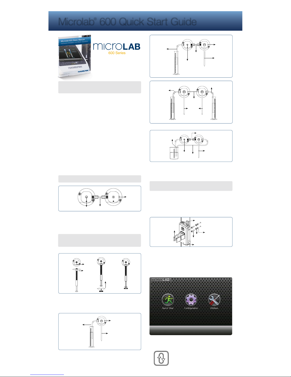
12. Prime the Instrument: Press the Prime button on the front of
the syringe drive to fill the syringes with li quid from the reser voir
and dispense it out the hand probe to waste. Continue to prime
the syringes until a ll air is flushed from the tubing
and syringes. Press the Prime button again to
stop the priming. For a Dilu ter setup, make sure
the dispense tubing from the hand probe is
submersed in the diluent reser voir to prime
the right syringe. (S ection 4.4)
Prime Button
Page 2
15. Write the serial number of your instrument here:
ML600
Letters Numbers
© 2015 Hamilton Company. All rights reserved.
All trademarks are owned and/or registered by Hamilton Company in the U.S. and/or other countries.
Part Number 61492-01 Rev E
Hamilton Americas & Pacific Rim
Hamilton Company Inc.
4970 Energy Way
Reno, Nevada 89502 USA
Tel: +1-775-858-3000
Fax: +1-775-856-7259
sales@hamiltoncompany.com
Hamilton Europe, Asia, & Africa
Hamilton Bonaduz A.G.
Via Crusch 8
CH-7402 Bonaduz, Switzerland
Tel: +41-58-610-10-10
Fax: +41-58-610-00-10
contact@hamilton.ch
To find a representative in your area, please visit hamiltoncompany.com/contacts.
Web: www.hamiltoncompany.com
USA: 800-648-5950
Europe: +41-58-610-10-10
13. Basic Operation: The hardware is now setup and ready to
perform the desired application. For the Basic Setup, press
the Back button on the bottom left of the Config uration Screen
and then select the Quick Star t button to begin dispensing.
Refer to Section 4.5 for a detailed description on how the
instrument will b ehave as a Single Syringe Dispenser,
Dual Syringe Diluter, Dual Syringe Dis penser or Contin uous
Dispenser. To complete the Advanced setup proceed to
the next step, otherwise skip to Step 15.
Free Extended Warranty
Register to extend the warranty to 24 months
from the manufacture date.
Register at www.ham-info.com/microlab-register
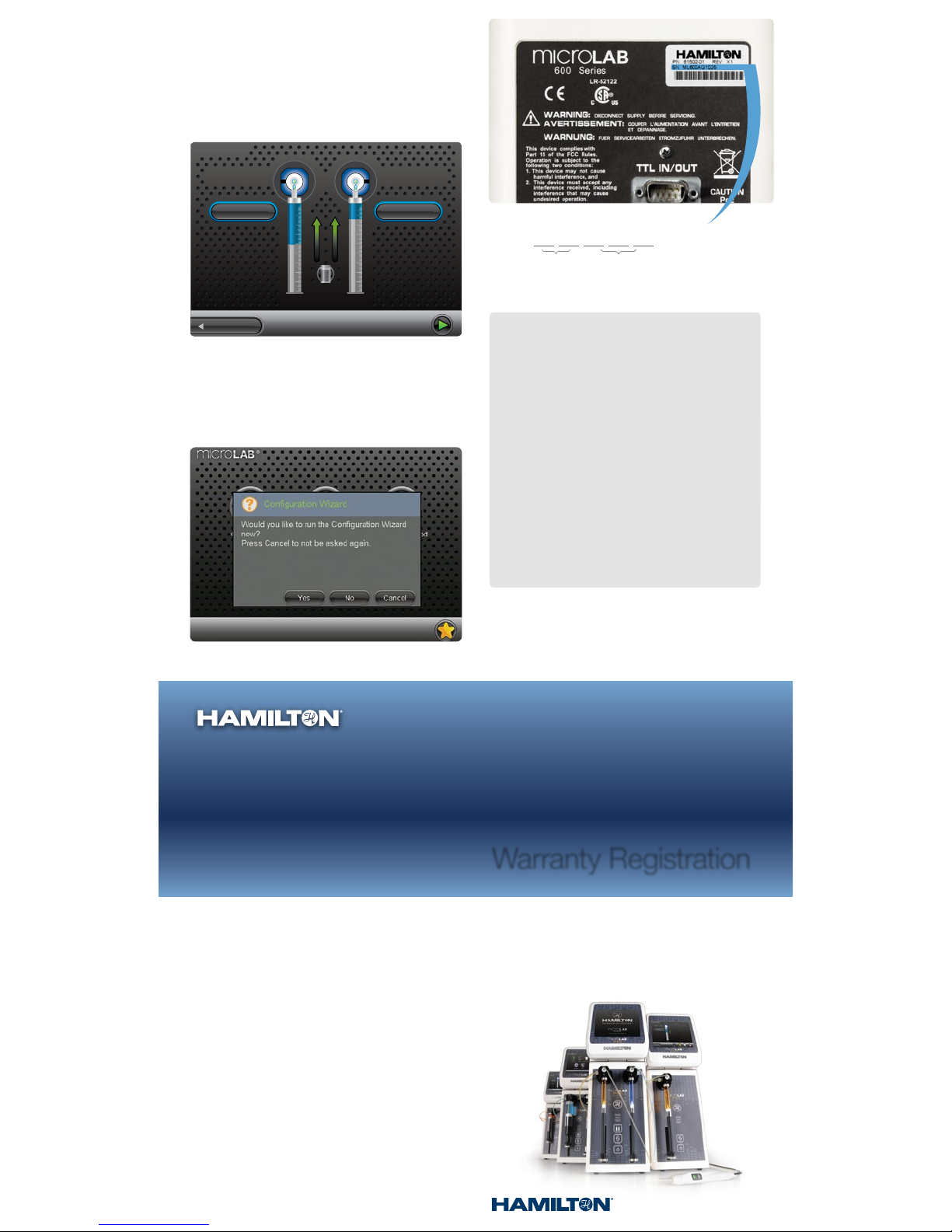
14. Advanced Operation: Turn the pump off and install the Hardware
Key (SD card) and then power the instrument On. If de sired, run
the Configuration Wizard to configure the hardware, password
protection and method logging settings. If these functions are
not desired, hit No or Ca ncel to not be asked again. To install the
optional printer, refer to the Quick Start Guide incl uded with the
printer. Once the pump is configured, refer to the Advanced Manual
to determine which Wizard will accomplish the desired application.
16. Register your instrument at
www.ham-info.com/microlab-register
Technical Support
If a problem persists even after attempts to correct it, contact
Hamilton Company Technical Support or Service Department.
To expedite service, please have the instrument pa rt number
and serial number ready and available. Please be abl e to
provide application specific infor mation (syringe sizes, drive
speeds and liquids).
In the United States
and Canada:
Hamilton Company, Inc.
4970 Energy Way
Reno, Nevada 89502
USA
Customer Service
(888) 525-2123
Technical Support/Service
(800) 648- 5950
Outside the U.S.
+1 (775) 858-3000
In Switzerland:
Hamilton Bonaduz A.G.
Via Crusch 8
Ch-7402 Bonaduz,
Switzerland
Customer Service
+41 5 8- 610 -10-10
Fax +41 58-610-00-10
Quick Start
µL
2.5 mL 1000.00 µL
Refill OFF
Main Menu
2500
µL
1000
Ready Ready
Warranty Registration
 Loading...