

Page 1

Table of Contents
1. CONCEPT AND HISTORY OF THE FG5 ..................................... 1-1
1.1. The FG5 Absolute Gravimeter .................................................................................... 1-1
1.2. HISTORY...................................................................................................................... 1-1
1.3. FG5 Design Features .................................................................................................... 1-2
2. DESIGN: COMPONENTS AND FUNCTION................................. 2-1
2.1. The Dropping Chamber ............................................................................................... 2-2
2.1.1. TEST MASS ........................................................................................................... 2-5
2.1.2. DRIVE MECHANISM ........................................................................................... 2-6
2.1.3. SERVICE RING ..................................................................................................... 2-6
2.1.4. VIEWING PORT.................................................................................................... 2-7
2.1.5. THE DROP ............................................................................................................. 2-7
2.2. The Interferometer ....................................................................................................... 2-9
2.2.1. LASER....................................................................................................................2-9
2.2.2. OPTICS AND BEAM PATH ................................................................................. 2-9
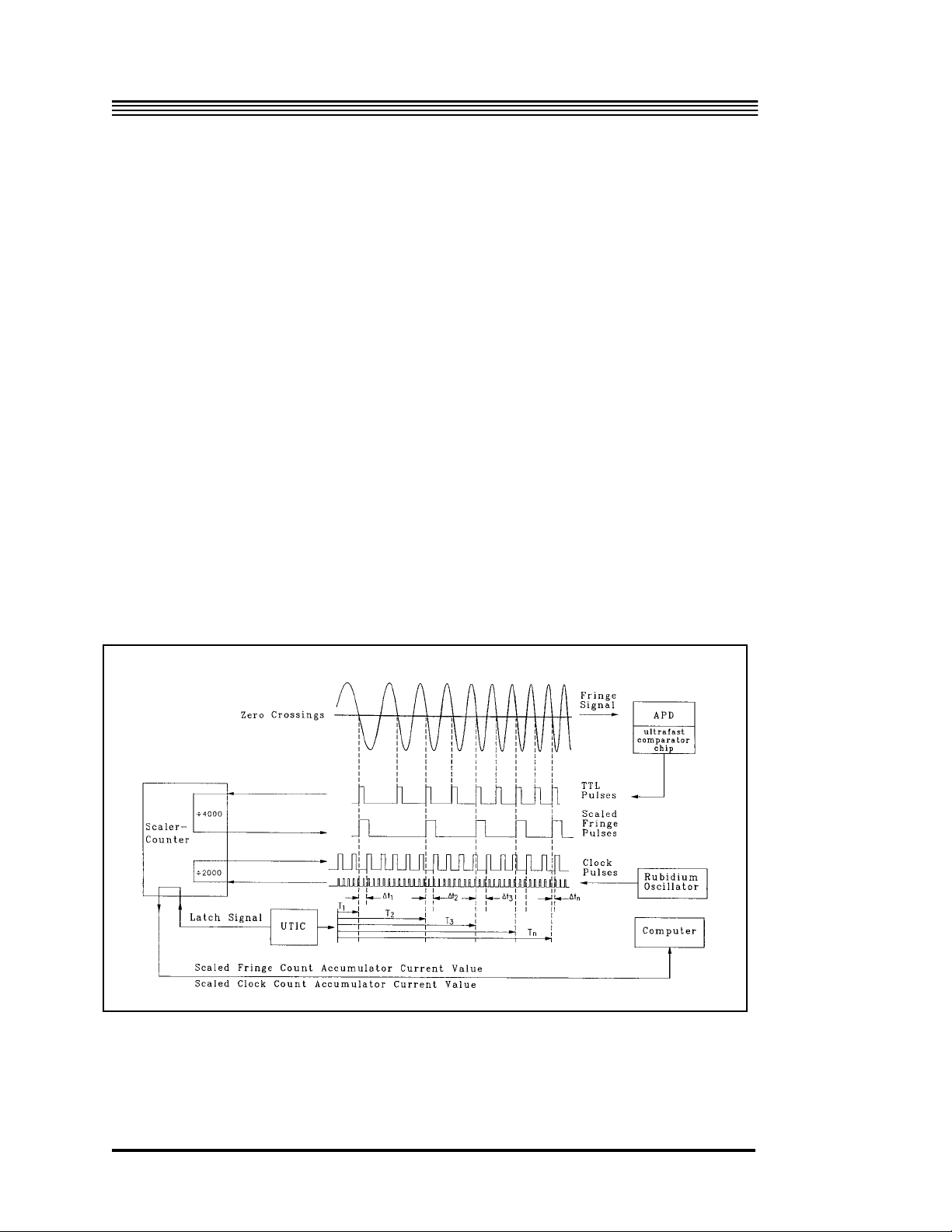
2.3. The Superspring.......................................................................................................... 2-13
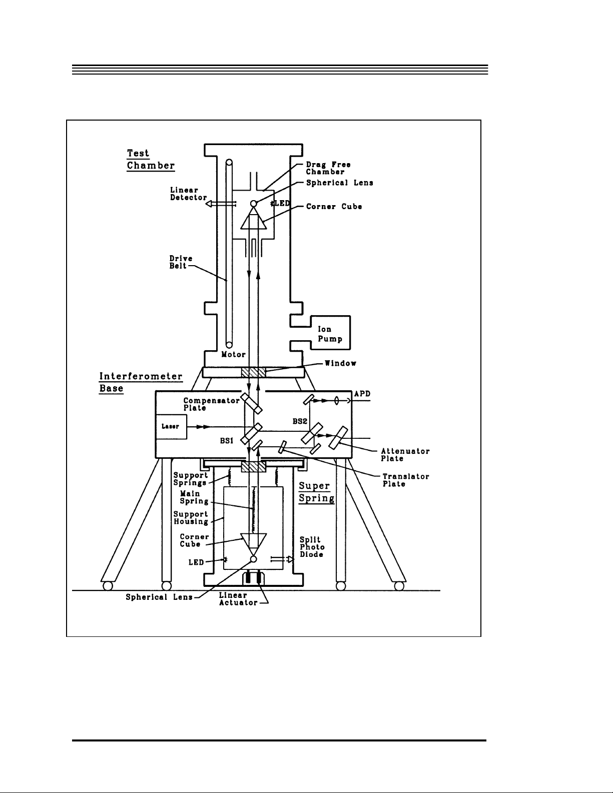
2.3.1. SUPERSPRING MASS ........................................................................................ 2-13
2.3.2. SPHERE DETECTOR SYSTEM ......................................................................... 2-13
2.4. The System Controller................................................................................................ 2-15
2.4.1. REQUIRED HARDWARE .................................................................................. 2-16
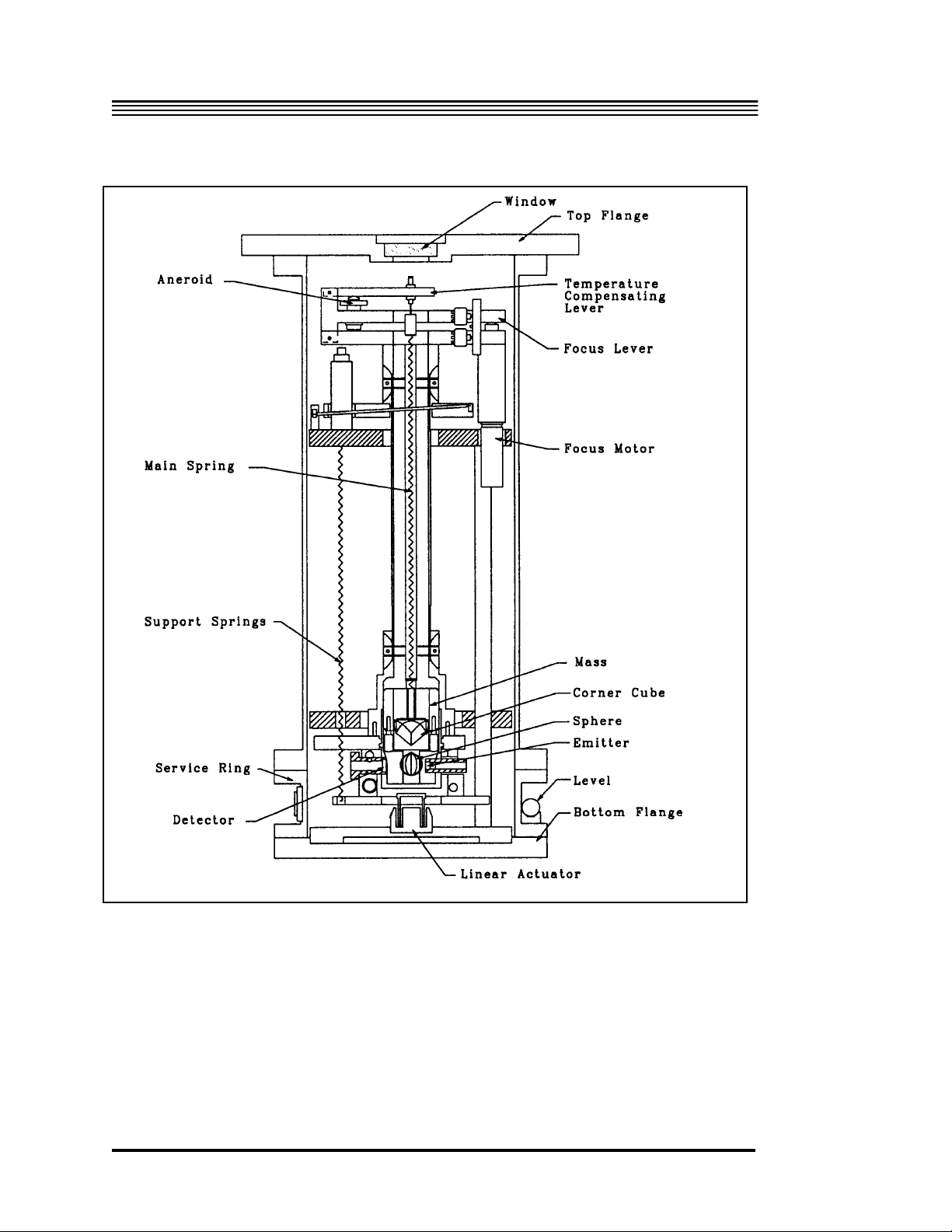
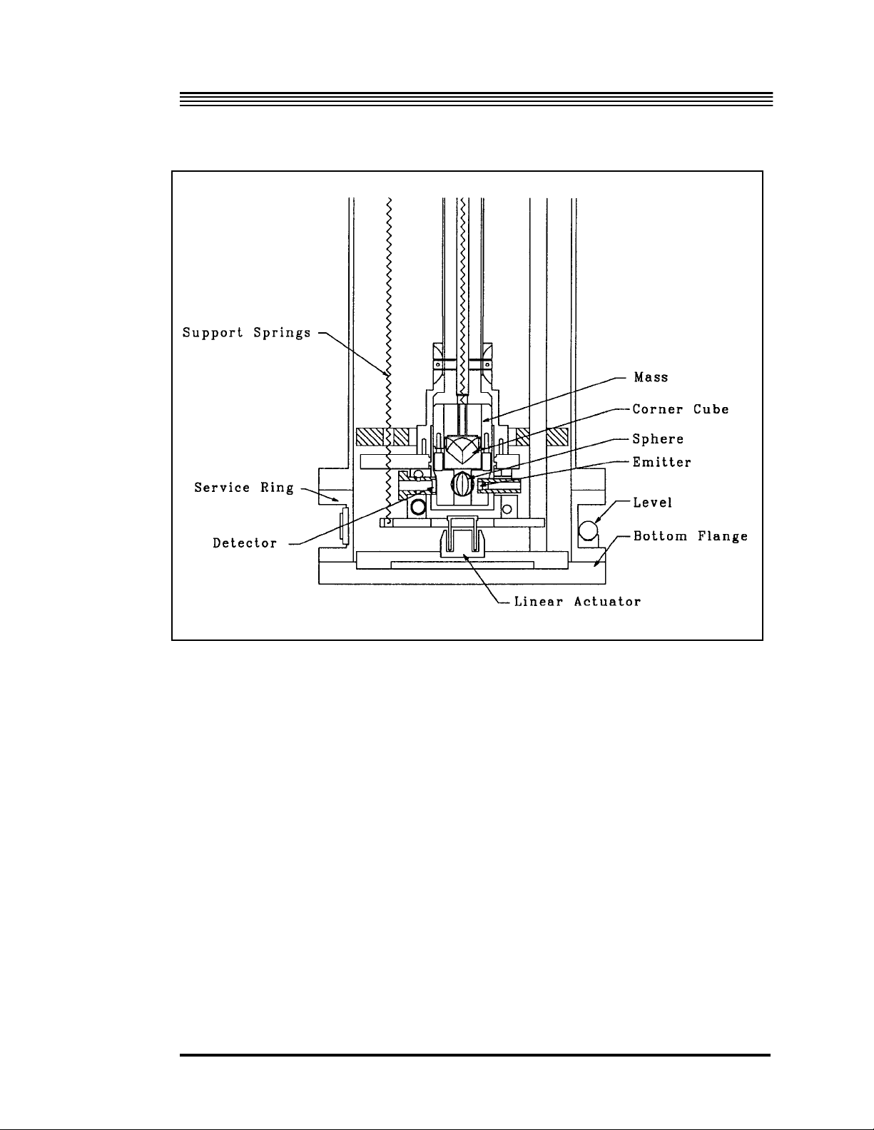
2.4.2. OPTIONAL HARDWARE................................................................................... 2-16
2.4.3. SOFTWARE ......................................................................................................... 2-16
2.5. Electronics ................................................................................................................... 2-17
2.5.1. TIMING SYSTEM ............................................................................................... 2-17
2.5.2. DROPPER CONTROLLER ................................................................................. 2-19
2.5.3. SUPERSPRING CONTROLLER......................................................................... 2-19
2.5.4. LASER CONTROLLER....................................................................................... 2-20
2.5.5. POWER SUPPLIES.............................................................................................. 2-20
2.5.6. OPTIONAL SYSTEMS........................................................................................ 2-21
2.5.6.1. ENVIRONMENTAL SENSORS.................................................................. 2-21
2.5.6.2. ROTATION MONITOR............................................................................... 2-21
3. HOW TO SET UP AND RUN THE FG5 ........................................ 3-1
3.1. Setting Up the FG5 ....................................................................................................... 3-1
3.1.1. INTERFEROMETER ............................................................................................. 3-1
3.1.2. ELECTRONICS CASE .......................................................................................... 3-2
3.1.2.1. Model AL-1 Laser:.......................................................................................... 3-3
3.1.2.1.1. Warm Up ................................................................................................. 3-3
i
Page 2

Table of Contents
3.1.2.1.2. Operation ................................................................................................. 3-3
3.1.2.2. WEO Model 100 Laser.................................................................................... 3-4
3.1.3. DROPPING CHAMBER TRIPOD......................................................................... 3-4
3.1.4. ION PUMP.............................................................................................................. 3-6
3.1.5. ROUGH LEVELING INTERFEROMETER.......................................................... 3-7
3.1.6. DROPPER VERTICALITY.................................................................................... 3-8
3.1.7. BEAM VERTICALITY .......................................................................................... 3-8
3.1.8. VERTICAL ADJUSTMENT OF THE TEST BEAM ............................................3-9
3.1.9. REFERENCE HEIGHT ........................................................................................3-11
3.1.10. THE SUPERSPRING.......................................................................................... 3-13
3.1.11. TRAVEL LOCK .................................................................................................3-14
3.1.12. CONNECT REMAINING SYSTEM CABLES .................................................3-14
3.1.13. SUPERSPRING ZERO-POSITIONING ............................................................3-16
3.1.14. FRINGE OPTIMIZING ......................................................................................3-17
3.1.15. Dropper Controller .............................................................................................. 3-19
3.2. Running the FG5 ......................................................................................................... 3-19
3.2.1. SYSTEM CONTROLLER SETUP....................................................................... 3-19
3.2.2. PROGRAM SETUP .............................................................................................. 3-20
3.3. Shutting Down the FG5 .............................................................................................. 3-20
3.3.1. COMPUTER ......................................................................................................... 3-20
3.3.2. SUPERSPRING ....................................................................................................3-22
3.3.3. INTERFEROMETER............................................................................................ 3-22
3.3.3.1. OPTION 1: Model AL-1 Laser..................................................................... 3-22
3.3.3.1. ........................................................................................................................3-22
3.3.3.2. OPTION 2: WEO Model 100 Laser .............................................................. 3-22
3.3.3.2. ........................................................................................................................ 3-22
3.3.4. DROPPING CHAMBER ......................................................................................3-23
3.3.5. POWER................................................................................................................. 3-23
3.4. Disassembling and Packing the FG5 .........................................................................3-23
3.4.1. ELECTRONICS:................................................................................................... 3-23
3.4.2. SYSTEM CONTROLLER.................................................................................... 3-24
3.4.3. ROTATION MONITOR (IF INCLUDED) .........................................................3-24
3.4.4. DROPPING CHAMBER ......................................................................................3-25
3.4.5. TRIPOD................................................................................................................. 3-25
3.4.6. SUPERSPRING ....................................................................................................3-25
3.4.7. INTERFEROMETER............................................................................................ 3-26
3.4.8. TURBO PUMP (IF USED) ................................................................................... 3-26
4. ADJUSTMENT AND MAINTENANCE........................................... 4-1
4.1. The Dropping Chamber................................................................................................ 4-1
4.1.1. REPLACEMENTS AND ADJUSTMENTS...........................................................4-1
4.1.1.1. Removing The Dropping Chamber Cover....................................................... 4-1
4.1.1.2. Replacing the Dropping Chamber Cover......................................................... 4-2
4.1.1.3. Replacing the Drive Belt ................................................................................. 4-2
4.1.1.4. Adjusting the Drive Belt Tension .................................................................... 4-3
4.1.1.5. Replacing the Ferrofluidic Vacuum Feedthrough............................................4-3
ii
Page 3

Table of Contents
4.1.1.6. Replacing the V-Plate...................................................................................... 4-4
4.1.1.7. Replacing the Linear Bearings ........................................................................ 4-5
4.1.1.8. Replacing the Shaft Bearings—Drive Pulley .................................................. 4-6
4.1.1.9. Replacing the Shaft Bearings—Top Pulley..................................................... 4-7
4.1.1.10. Replacing the Rotary Shaft Encoder ............................................................. 4-7
4.1.1.11. Pumping Down the Dropping Chamber........................................................ 4-8
4.2. The Interferometer ....................................................................................................... 4-9
4.2.1. TROUBLESHOOTING THE BEAM PATH ......................................................... 4-9
4.2.2. ALIGNMENT......................................................................................................... 4-9
4.2.2.1. Laser................................................................................................................ 4-9
4.2.2.2. Standard Optical Isolator................................................................................. 4-9
4.2.2.3. /2-Faraday Isolator combination ................................................................... 4-10
4.2.2.4. Optical Isolator Replacement ........................................................................ 4-10
4.2.2.5. Adjusting mirrors 1 and 2-The first two mirrors........................................... 4-10
4.2.2.6. Beam Expander ............................................................................................. 4-11
4.2.2.6.1. Focusing lens:........................................................................................ 4-11
4.2.2.6.2. Collimating lens:.................................................................................... 4-12
4.2.2.7. Leveling the Tripod Tray .............................................................................. 4-12
4.2.2.8. Making the test beam vertical using the alcohol reference surface............... 4-12
4.2.2.9. Leveling the Dropper .................................................................................... 4-13
4.2.2.10. Setting the Bubble Levels on the Tripod..................................................... 4-14
4.2.2.11. Adjusting Mirrors 3 & 4 to steer beam through dropper and make beam
vertical. ..................................................................................................................................... 4-14
4.2.2.12. Adjusting the Superspring position and final adjustment mirror ................ 4-15
4.2.2.13. Final Mirror Translation-Getting Beams Overlapped In Fringe Viewer..... 4-16
4.2.2.14. Adjusting the APD signal detector.............................................................. 4-16
4.2.2.15. Adjusting The Fringe Amplitude ................................................................ 4-17
4.2.2.16. Replace all covers and tighten all screws.................................................... 4-17
4.3. The Superspring.......................................................................................................... 4-18
4.3.1. REPLACEMENTS AND ADJUSTMENTS ........................................................ 4-18
4.3.1.1. Removing the Superspring Cover ................................................................. 4-18
4.3.1.2. Removing the Service Ring........................................................................... 4-18
4.3.1.3. Replacing the Coil (Linear Actuator)............................................................ 4-19
4.3.1.4. The Mass Mainspring/Hanger....................................................................... 4-20
4.3.1.5. Replacing the Flexures .................................................................................. 4-20
4.3.1.6. Assembling the Superspring.......................................................................... 4-22
4.3.1.7. Replacing the Focus Lever Motor ................................................................. 4-24
4.3.1.8. Adjusting the Micro-Switches....................................................................... 4-24
4.3.1.9. The Aneroid Wafer Assembly....................................................................... 4-24
4.3.1.10. The Delta Rods............................................................................................ 4-24
4.4. Timing System and Data Acquisition........................................................................ 4-25
4.4.1. TIMING ................................................................................................................ 4-25
4.4.1.1. Avalanche Photo Diode Printed Circuit Board ............................................. 4-26
4.4.1.2. APD Board and Photo Diode Supply Module............................................... 4-26
4.4.1.3. Scaler-Counter Printed Circuit Board ........................................................... 4-28
4.4.1.4. Rubidium Oscillator ...................................................................................... 4-32
4.4.1.5. Universal Time Interval Counter................................................................... 4-32
4.4.2. DATA ACQUISITION......................................................................................... 4-34
iii
Page 4

Table of Contents
4.4.2.1. Computer Interface Cards.............................................................................. 4-34
4.5. DROPPER CONTROLLER ...................................................................................... 4-35
4.5.1. DROPPER CONTROL MODES ..........................................................................4-36
4.5.1................................................................................................................................. 4-36
4.5.1................................................................................................................................. 4-36
4.5.1.1. STANDBY ....................................................................................................4-36
4.5.1.1.1. To Select ................................................................................................ 4-36
4.5.1.1.2. Function ................................................................................................. 4-36
4.5.1.1.3. To Deselect ............................................................................................4-36
4.5.1.2. MANUAL...................................................................................................... 4-36
4.5.1.2.1. To Select: ............................................................................................... 4-36
4.5.1.2.2. Function: ................................................................................................ 4-37
4.5.1.3. DROP............................................................................................................. 4-37
4.5.1.3.1. To Select: ............................................................................................... 4-37
4.5.1.3.2. Function: ................................................................................................ 4-37
4.5.1.4. OSCILLATE ................................................................................................. 4-37
4.5.1.4.1. To Select: ............................................................................................... 4-37
4.5.1.4.2. Function: ................................................................................................ 4-37
4.5.2. Analog Servo
4.5.2.1. Cart-Position.................................................................................................. 4-38
4.5.2.2. Cart Velocity.................................................................................................. 4-39
4.5.2.3. Sphere Servo.................................................................................................. 4-39
4.5.2.4. Active Sphere Servo ...................................................................................... 4-40
4.5.2.5. Feedforward Sphere Servo ............................................................................4-40
4.5.3. Superspring Controller ..........................................................................................4-40
4.5.3.1. SUPERSPRING CONNECTIONS ............................................................... 4-41
4.5.3.2. MOTOR DRIVE SELECTION..................................................................... 4-42
4.5.3.2.1. OFF ........................................................................................................ 4-42
4.5.3.2.2. AUTO ....................................................................................................4-42
4.5.3.2.3. WINDOW.............................................................................................. 4-42
4.5.3.2.4. REMOTE ............................................................................................... 4-43
4.5.3.2.5. MANUAL.............................................................................................. 4-43
4.5.3.3. Active Servo .................................................................................................. 4-43
4.5.3.4. Coil Drive (Current Driver) ........................................................................... 4-43
4.5.4. Maintenance Schedule........................................................................................... 4-44
4.5.4.1. Annually ........................................................................................................4-44
4.5.4.2. Semi-annually................................................................................................ 4-44
......................................................................................................... 4-38
5. TROUBLESHOOTING .................................................................. 5-1
5.1. The FG5 System ............................................................................................................5-1
5.2. System Problems ...........................................................................................................5-1
5.2.1. DROPPING CHAMBER ........................................................................................5-1
5.2.2. INTERFEROMETER AND LASER ......................................................................5-4
5.2.3. SUPERSPRING ......................................................................................................5-7
5.2.4. SYSTEM CONTROLLER...................................................................................... 5-9
5.2.5. ELECTRONICS.................................................................................................... 5-10
5.2.6. ENVIRONMENTAL SENSORS PACKAGE ...................................................... 5-12
iv
Page 5

Table of Contents
5.2.7. ROTATION MONITOR....................................................................................... 5-13
5.3. Gravity Site Selection ................................................................................................. 5-14
5.3.1. GEOLOGIC STABILITY..................................................................................... 5-14
5.3.2. SITE STABILITY ................................................................................................ 5-14
5.3.3. ENVIRONMENTAL NOISE ............................................................................... 5-14
5.3.4. TEMPERATURE STABILITY ............................................................................ 5-14
5.4. AC POWER ................................................................................................................ 5-16
6. SWITCHING THE AC POWER ..................................................... 6-1
6.1. LASER ........................................................................................................................... 6-1
6.1.1. WEO Model 100 Laser ........................................................................................... 6-1
6.1.2. AL-1 Laser .............................................................................................................. 6-1
6.2. UTIC .............................................................................................................................. 6-1
6.3. MAIN POWER SUPPLY............................................................................................. 6-2
6.4. Portable Ion Pump Power Supply............................................................................... 6-2
6.5. Computer....................................................................................................................... 6-3
6.6. Docking Station............................................................................................................. 6-3
6.7. IOtech ADC16...............................................................................................................6-3
6.8. Turbo pump .................................................................................................................. 6-3
7. PUMPING/BAKING THE CHAMBER ........................................... 7-1
7.1. Choosing the Pumping Method ................................................................................... 7-1
7.1.1. Cold Pumping the Chamber.................................................................................... 7-1
7.1.2. Baking Out the Chamber......................................................................................... 7-1
7.2. Connecting the Turbo Pump to the Dropping Chamber .......................................... 7-2
7.3. Heating the Chamber ................................................................................................... 7-3
7.4. Starting the Ion Pump .................................................................................................. 7-4
8. THE ROTATION MONITOR.......................................................... 8-1
8.1. INSTALLATION.......................................................................................................... 8-1
8.2. THE DATA LOGGING SYSTEM.............................................................................. 8-2
v
Page 6

Table of Contents
8.3. TAKING DATA ............................................................................................................ 8-2
9. CHECKLISTS AND LOGS............................................................ 9-1
9.1. Switching the AC Power............................................................................................... 9-2
9.1........................................................................................................................................... 9-2
9.2. FG5 Setup ......................................................................................................................9-4
9.3. Dropping Chamber Pump Down and Bake-Out ........................................................ 9-8
9.4. Dropping Chamber Maintenance ................................................................................ 9-9
9.4.1. Removing Chamber Cover...................................................................................... 9-9
9.4.2. Replacing Dropping Chamber Cover .................................................................... 9-10
9.4.3. Replacing Drive Belt ............................................................................................. 9-11
9.4.4. Adjust Belt Tension............................................................................................... 9-13
9.4.5. Replace Ferrofluidic Vacuum Feedthrough ..........................................................9-13
9.4.6. Replacing V-plate.................................................................................................. 9-14
9.4.7. Replacing the Linear Bearings ..............................................................................9-16
9.4.7................................................................................................................................. 9-16
9.4.8. Replacing Shaft Bearings (Drive Pulley) ..............................................................9-18
9.4.9. Replacing Shaft Bearings (Top Pulley) ................................................................. 9-19
9.4.10. Replacing Rotary Shaft Encoder .........................................................................9-20
9.5. Interferometer Alignment ..........................................................................................9-22
9.5......................................................................................................................................... 9-22
9.6. Superspring Maintenance........................................................................................... 9-23
9.6.1. Removing Superspring Cover ...............................................................................9-23
9.6.2. Replacing Superspring Cover................................................................................ 9-23
9.6.3. Removing Service Ring......................................................................................... 9-24
9.6.4. Replacing Coil....................................................................................................... 9-24
9.6.5. Replacing Flexures ................................................................................................ 9-26
9.6.6. Assembling Superspring........................................................................................ 9-28
9.6.7. Replacing Focus Lever Motor ............................................................................... 9-30
9.6.8. Adjusting Micro-Switches..................................................................................... 9-31
9.7. Packing the FG5 .......................................................................................................... 9-31
10. INDEX........................................................................................ 10-1
vi
Page 7

Concept and History of the FG5 1
1. Concept and History of the FG5
1.1. The FG5 Absolute Gravimeter
The FG5 absolute gravimeter is a high precision, high accuracy, transportable
instrument that measures the vertical acceleration of gravity (g). The
operation of the FG5 is simple in concept. A test mass is dropped vertically
by a mechanical device inside a vacuum chamber, and then allowed to fall a
distance of about 20cm. The FG5 uses a laser interferometer to accurately
determine the position of the free-falling test mass as it accelerates due to
gravity. The acceleration of the test mass is calculated directly from the
measured trajectory.
The laser interferometer generates optical interference fringes as the test mass
falls. The fringes are counted and timed with an atomic clock to obtain precise
time and distance pairs. These data are fit to a parabolic trajectory to give a
measured value for g. This method of measuring gravity is absolute because
the determination is purely metrological and relies on standards of length
and time. The distance scale is given by a frequency stabilized helium neon
(HeNe) laser used in the interferometer. A rubidium atomic time-base
provides the time scale used for the accurate timing. The value of gravity
obtained with the FG5 can be used without the loop reductions and drift
corrections normally required when using relative instrumentation.
1.2. HISTORY
The FG5 is a new generation of absolute gravimeter based on technology
developed over the last thirty years by Dr. James Faller of the National
Institute of Standards and Technology (NIST), and his colleagues. Beginning
with a white-light-fringe interferometric system built in 1962, Faller and
coworkers have continuously improved the designs of the instruments. The
most recent predecessors of the FG5 was the series of six JILAg gravimeters,
built in 1985 at the Joint Institute of Laboratory Astrophysics (JILA), with
support from NIST, the Defense Mapping Agency (DMA), the National
Oceanographic and Atmospheric Administration (NOAA), the Canadian
1-1
Page 8

Concept and History of the FG5 1
Geophysical Survey (GSC), the University of Hanover Institute for Earth
Measurement, Germany, the Finnish Geodetic Institute, Finland, and the
University of Vienna Institute for Metrology and Geophysics, Austria.
1.3. FG5 Design Features
The FG5 incorporates a number of significant advancements in design which
reduce or eliminate systematic errors identified in the earlier versions, and
which make the FG5 easier to use. These improvements are:
• An inline interferometer beam path which eliminates systematic errors
from tilt-induced path length changes.
• Complete redesign of the Superspring, a device for providing an inertial
mass that contains a retroreflective corner cube. The new Superspring has
improved performance, and at the same time greatly reduced size. The
drift problems of earlier designs have been reduced substantially.
• Completely new tripod design, which supports the test chamber, for
extra stability. The tripod is now built symmetrically with respect to the
drop line.
• The system controller has been updated to a 486-type personal
computer with a standard language interface. The decision to use
standard PC technology has allowed the FG5 to offer more computing
power while reducing the size of the instrument.
• Improvements to the electronics reflect new technology and make the
instrument smaller and easier to use.
• A user-friendly full-featured real-time software program takes
interferometer data and environmental data. This software provides an
immediate value for the local gravity in real-time.
• A user-friendly full-featured post-processing software program that
allows complete ability to vary data analysis procedures and to vary
environmental corrections.
• This absolute gravimeter is designed to work with a new rugged iodinestabilized laser system (WEO model 100) traceable to the BIPM.
1-2
Page 9
Design: Components and Function 2
2. Design: Components and Function
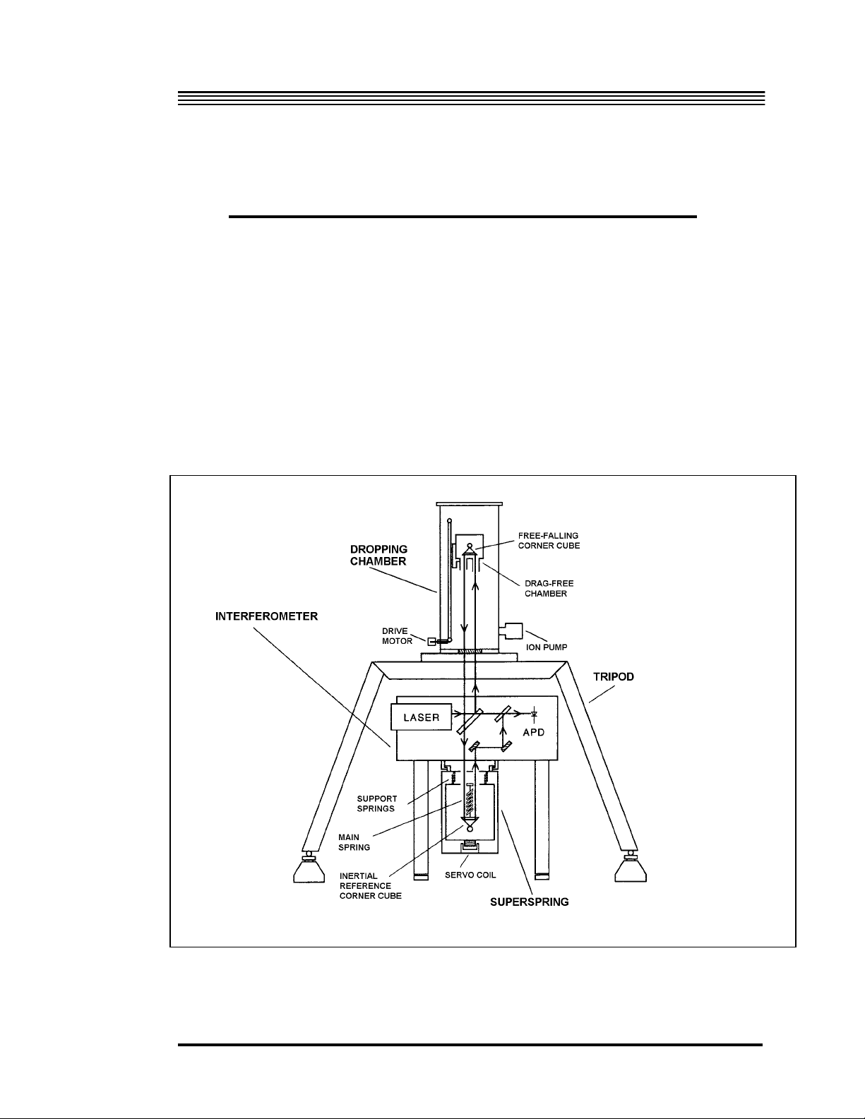
The FG5 System (Figure 2-1) consists of a: Dropping Chamber,
Interferometer, Superspring, System Controller, and Electronics. A test
mass is allowed to free-fall inside the evacuated Dropping Chamber. The
Interferometer is used to monitor the position of the freely-falling test mass.
The Superspring is an active long-period isolation device used to provide an
inertial reference for the gravity measurement. The System Controller
(computer) allows a flexible user interface, controls the system, acquires data,
analyzes data, and stores the results. The Electronics provides high accuracy
timing necessary for the measurement and provides system servo control.
Figure 2-1 The FG5 System
2-1
Page 10
Design: Components and Function 2
2.1. The Dropping Chamber
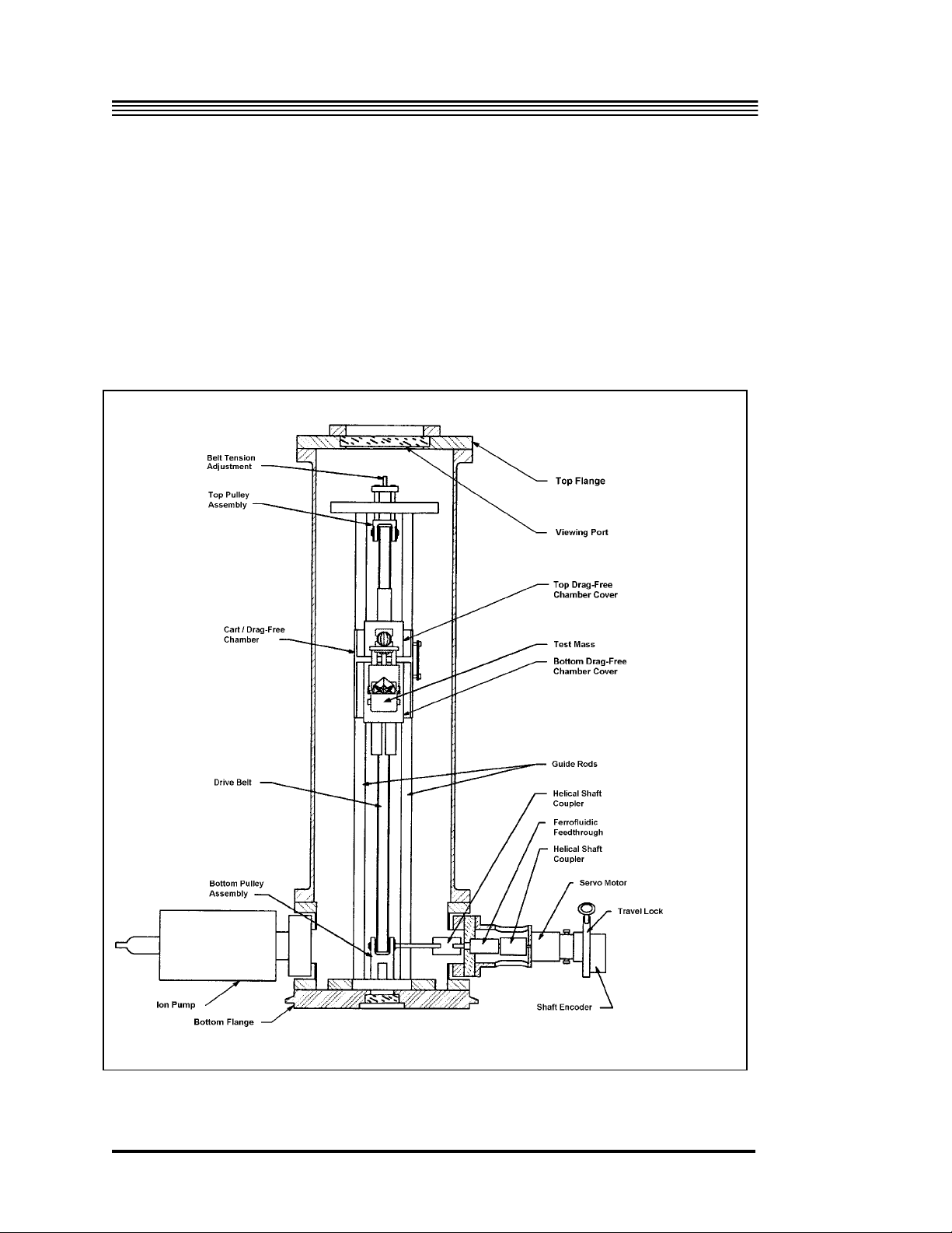
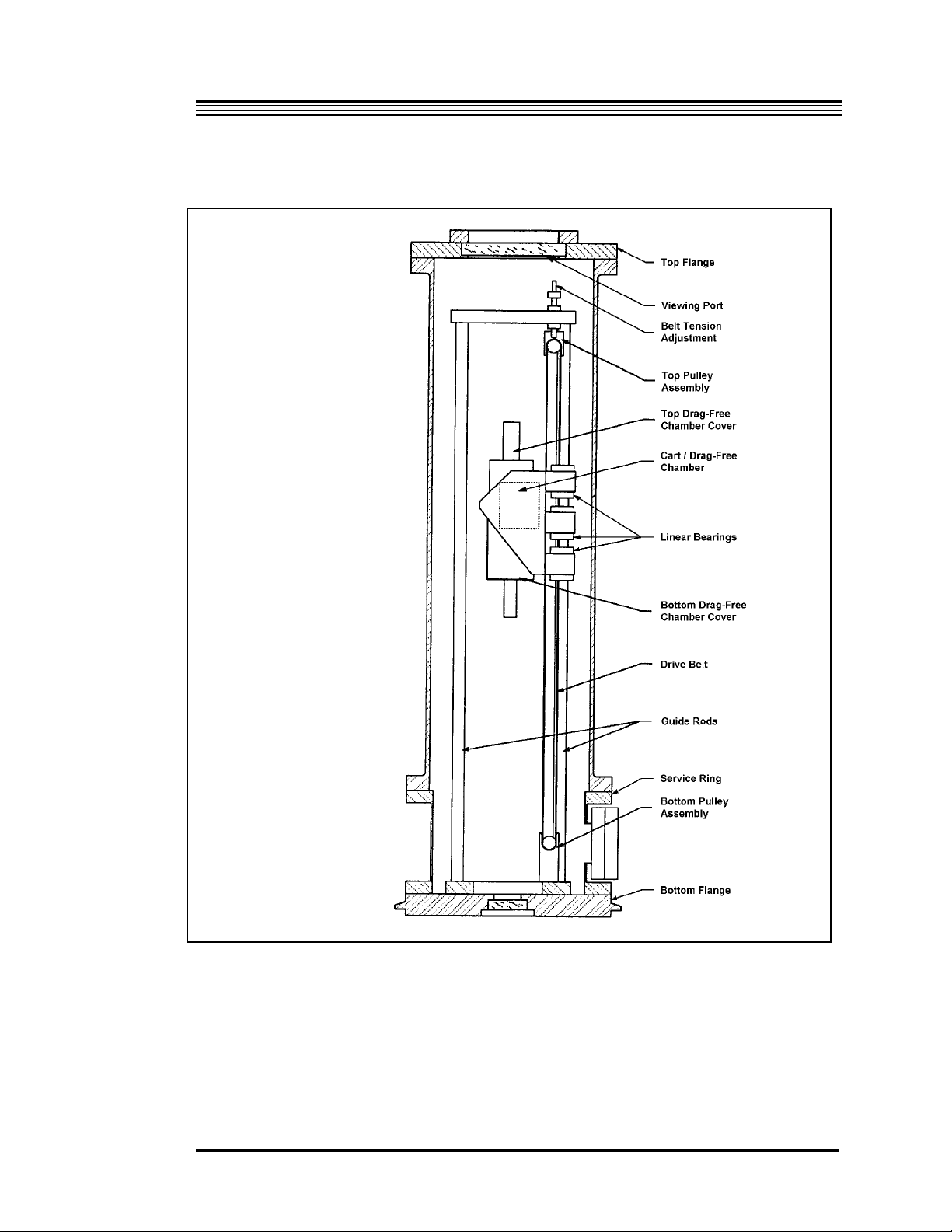
The Dropping Chamber (Figure 2-2 and Figure 2-3) is an evacuated
chamber which contains the Cart/Drag-Free Chamber which houses the Test
Mass. A Drive Mechanism is used to drop, track, and catch the test mass
inside the drag-free chamber. Laser light (Figure 2-1) passes through a
window in the bottom of the Dropping Chamber to the corner cube (inside
the test mass), then is reflected back down through the window to the
interferometer.
Figure 2-2 Front view of the dropping chamber
2-2
Page 11
Design: Components and Function 2
Figure 2-3 Side view of the dropping chamber
CART/DRAG-FREE CHAMBER
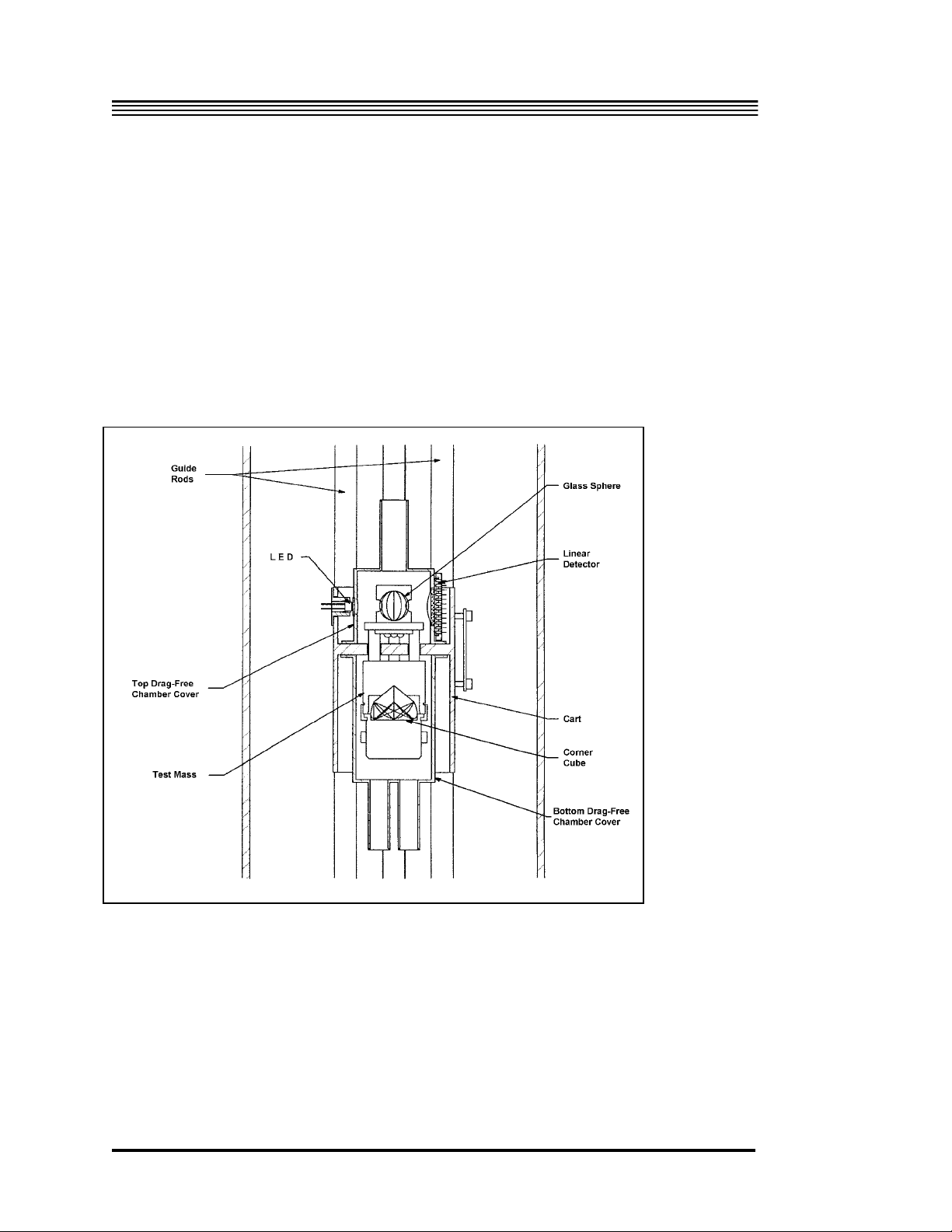
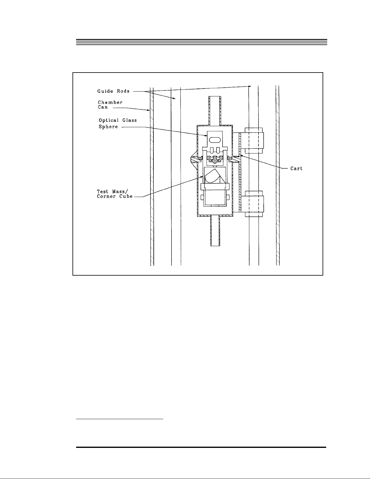
The cart /drag-free chamber (Figure 2-4 and Figure 2-5) houses the test mass.
The purpose of the drag-free chamber is to reduce the residual air drag inside
the evacuated dropping chamber. The chamber also reduces magnetic and
electrostatic forces on the test mass, and provides a convenient method for
2-3
Page 12
Design: Components and Function 2
dropping and catching the test mass, as well as returning it to the top of the
chamber for the next drop. A Light Emitting Diode (LED) , located on the
cart, directs light through an optical glass sphere attached to the test mass.
The sphere focuses the light onto a linear detector, also mounted on the cart.
This system senses the position of the cart with respect to the test mass. A
servo-motor/drive belt system (Figure 2-2) moves the cart inside the
Dropping Chamber, using active feedback from the position sensor to
maintain the cart in a constant position relative to the test mass during freefall. Since there is essentially no relative motion between the test mass and
the drag-free chamber, the effects of residual air drag are eliminated.
Figure 2-4 Front view of the cart/drag-free chamber
2-4
Page 13
Design: Components and Function 2
Figure 2-5 Side view of the cart/drag-free chamber
2.1.1.TEST MASS
The Test Mass (Figure 2-4 and Figure 2-5) is a retroreflective corner cube
surrounded by a support structure and balanced at the optical center of the
corner cube. The corner cube is a three-surface mirror which has the special
optical property that the reflected beam is always parallel to the incident
beam. In addition, the phase shift of the reflected beam is virtually constant
with respect to any slight rotation or translation of the corner cube around its
1
optical center
1
Peck, Edson, J. Opt. Soc. Amer., 38, (1948)
2-5
.
Page 14
Design: Components and Function 2
2.1.2.DRIVE MECHANISM
The drive mechanism (Figure 2-2) is a support structure inside the dropping
chamber on which the cart/drag-free chamber travels up and down, driven
by a DC servo motor.
2.1.3.SERVICE RING
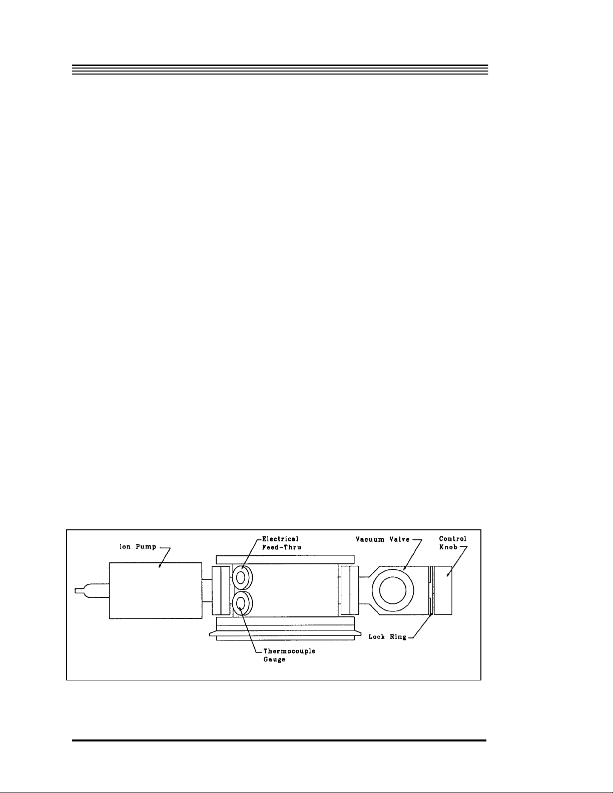
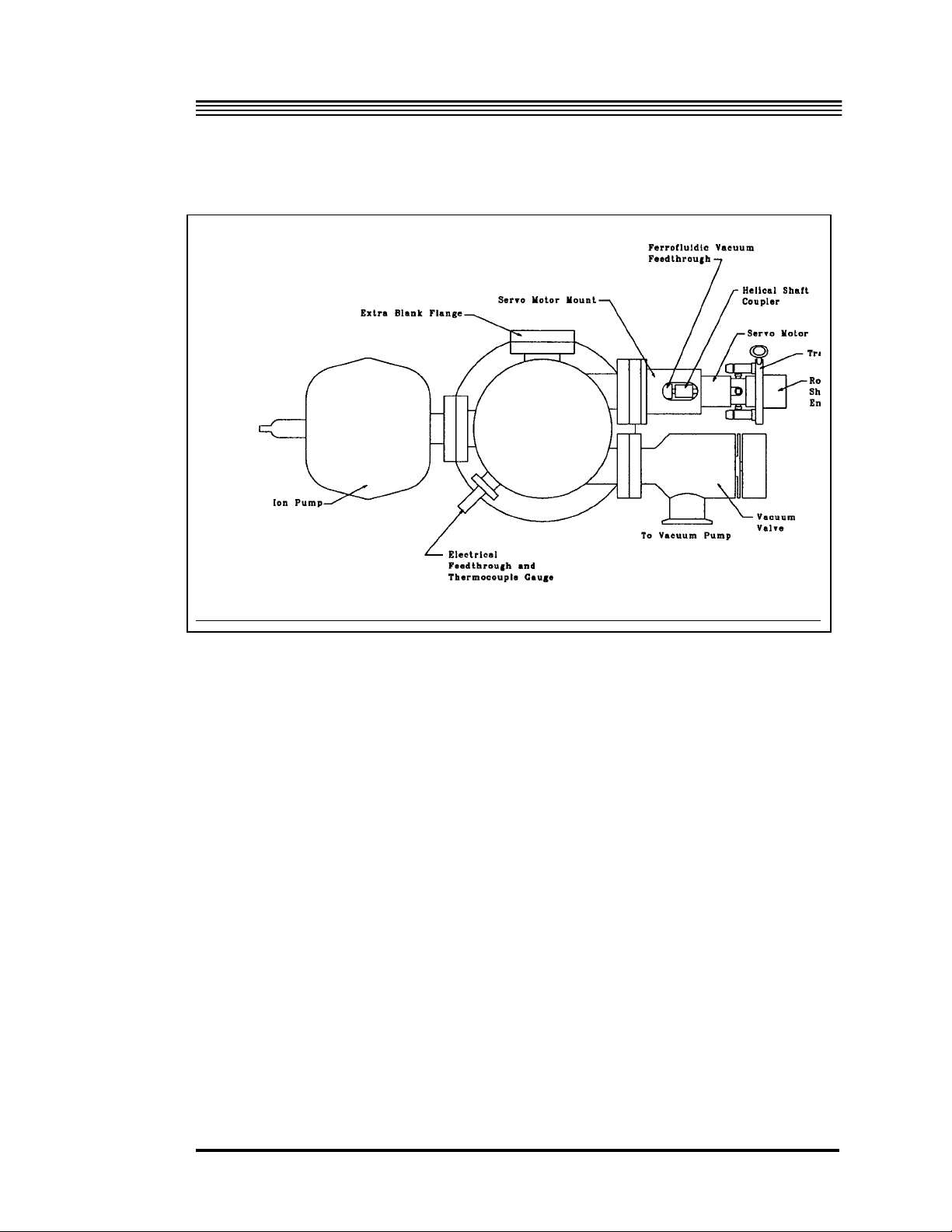
The Service Ring (Figure 2-6 and Figure 2-7) is the base of the Dropping
Chamber. It provides connection and mounting for the following:
• A bellows-type vacuum valve for the initial evacuation of the vacuum
system
• A Ferrofluidic rotary vacuum feedthrough which connects the motor
shaft to the cart drive mechanism
• A servo motor/rotary shaft encoder assembly which moves the cart
and senses its position
• An electrical vacuum feedthrough which allows connection of the test
mass tracking electronics to the controller
• An ion pump, mounted on a 2¾” Conflat flange, which maintains the
vacuum once the chamber has been evacuated by the roughing pump
• Spare 2¾” Conflat and Mini-Conflat flanges are blanked off, and can
be used for additional vacuum accessories
Figure 2-6. Side view of the service ring.
2-6
Page 15
Design: Components and Function 2
Figure 2-7 Top view of the service ring.
2.1.4.VIEWING PORT
The viewing port (Figure 2-2 and Figure 2-3) is located in the top flange of the dropping chamber. It allows visual observation of the dropping chamber interior when the rotation monitor is not fitted to the system. The rotation monitor (when fitted to the system) is mounted to the top flange of the dropping chamber, directly above the viewing port. When the rotation monitor is not mounted, a cover for the port is used to exclude ambient light from the interior of the dropping chamber during measurements.
2.1.5.THE DROP
In drop mode, a signal from the computer to the dropper controller initiates
the drop sequence. The cart drag-free chamber is driven slowly from its
bottom position to the “hold” position at the top of the drop. A second pulse
initiates the drop, and the cart accelerates downward at more than 1 g,
leaving the test mass in free-fall.
2-7
Page 16

Design: Components and Function 2
When the cart has traveled about 5 mm downward from the hold position (as
measured by the shaft encoder) a separation of about 3 mm between the cart
and test mass has been achieved. The dropper controller then uses feedback
from the linear detector to maintain this separation for the remainder of the
drop.
The free-falling test mass generates an interference fringe for each halfwavelength (λ/2) of its movement. As the mass accelerates downward, the
fringes occur more and more closely in time. The resulting signal from the
avalanche photo diode (APD) is a “chirped” sine wave (Figure 2-12) whose
frequency is proportional to the free-falling test mass’s velocity.
Approximately a million fringes are generated during a single drop. A zerocrossing discriminator (comparator) transforms the sinusoidal fringe signals
from the APD into a series of square Transistor-Transistor Logic (TTL)
pulses. The pulses are scaled (i.e., divided) by a user-defined factor (typically
4000) which is set in the scaler-counter. A universal time interval counter
(UTIC) measures the time interval between each scaled pulse. The g-program
fits each time and distance pair to a parabolic trajectory to determine the
value of g.
When the cart and test mass have descended past the catch point, the
controller signals the cart to reduce acceleration and then come to a stop. The
falling mass catches up to the descending cart and is brought gently to rest.
The system resets for the next drop. The entire sequence takes about 2
seconds and can repeated up to thirty times per minute.
2-8
Page 17

Design: Components and Function 2
2.2. The Interferometer
The interferometer is a massive, rigid cast aluminum housing which supports a laser and optics for splitting, directing, and recombining the laser beams.
2.2.1.LASER
The FG5 employs a stabilized helium-neon laser to provide an accurate and
stable wavelength used in the interferometric measurement system. There
are two lasers which are currently available for the FG5.
The Winters Electro-Optics Model 100 iodine stabilized laser. This laser is a
primary standard for the definition of the meter at the Bureau International
des Poids et Measures (BIPM) in Sevres, France. It is a highly stabilized
10
distance standard having an absolute frequency accuracy of 1 part in 10
kHz).
(50
The Micro-g Solutions Model AL-1 frequency/intensity stabilized HeNe laser
is characterized by a slow, linear drift. Unlike the WEO Model 100 Iodine
Laser, it must be periodically calibrated to achieve the best accuracy.
However, it is more rugged than the iodine laser.
2.2.2.OPTICS AND BEAM PATH
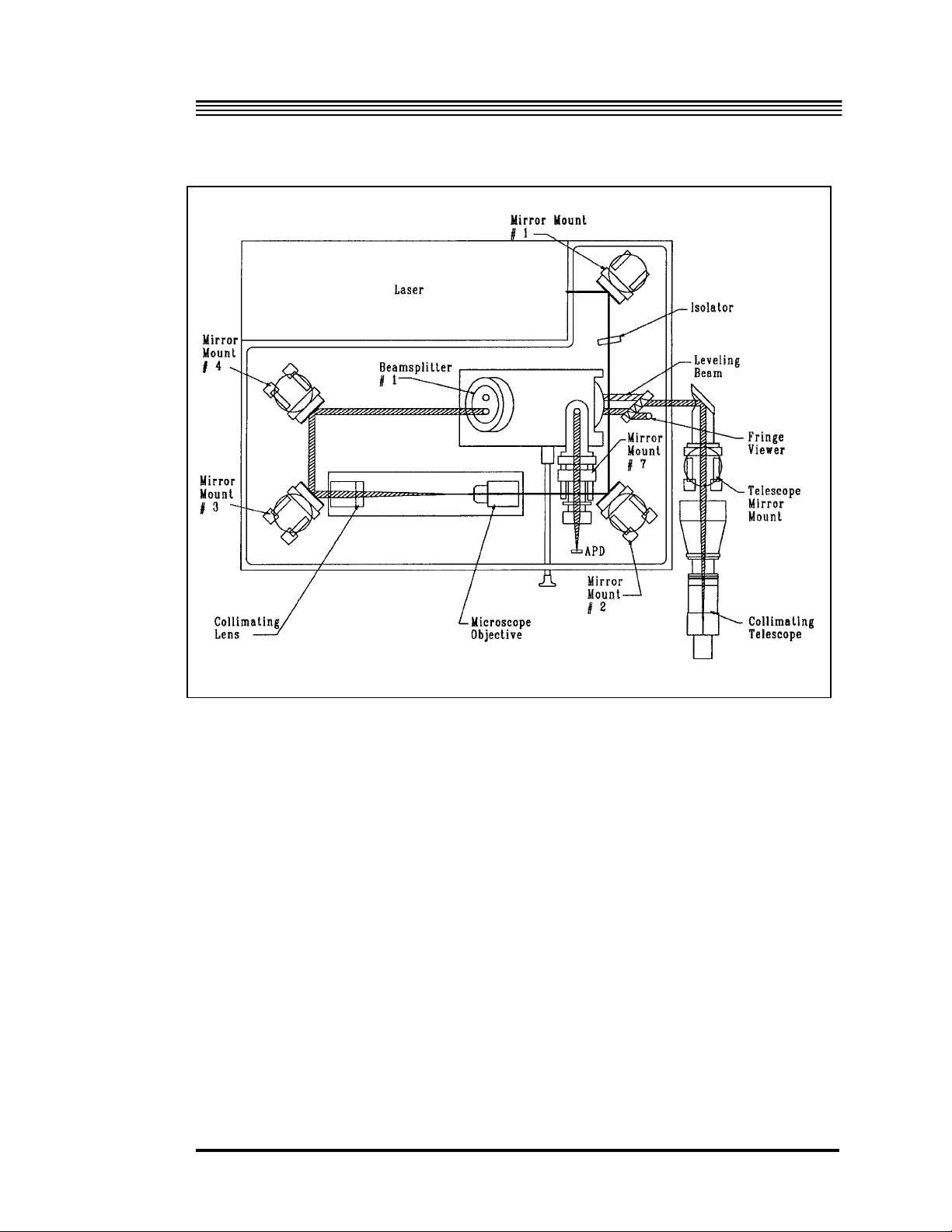
The laser beam (Figure 2-8 and Figure 2-9) is directed by mirror #1 through
the isolator plate to mirror #2. From there it passes through the focusing
optics (microscope objective), and the collimating lens, where the beam is
expanded. It is then directed to beamsplitter #1 by mirror #3 and mirror #4,
where it is split into the test beam and the reference beam. The reference
beam is split again at beamsplitter #2 and travels to the Avalanche Photo
Diode (APD). The path length of the reference beam remains constant. The
test beam is reflected vertically at beamsplitter #1, and passes through a
compensator plate and a window in the bottom of the Dropping Chamber. It
is then reflected back down by the corner cube in the test mass. The test
beam returns through the window, the compensator plate, and beamsplitter
#1 and passes down through the interferometer base to the Superspring.
2-9
Page 18

Design: Components and Function 2
The test beam passes through the top window of the Superspring chamber to
a corner cube in the Superspring mass. The test beam is then reflected back
through the window to the interferometer base, where it hits mirror #5,
passes through the translator plate, hits mirror #6, and is recombined with
the reference beam at beamsplitter #2.
This interferometer is a Mach-Zender interferometer with a fixed arm and a
variable (test) arm. During a drop, the motion of the test mass/corner cube
affects the path length of the test beam. The interference fringes which result
from the recombination of the test beam and the reference beam provide an
accurate measure of the motion of the test mass relative to the mass
suspended on the Superspring.
Two separate complementary, recombined beams are produced at
beamsplitter 2. The vertical recombined beam is reflected by mirror #7, and
is focused by a lens. The focused beam strikes the detector (APD), and the
interference fringes are converted to continuous wave (CW) signals and
transmitted to the scaler counter.
The other recombined beam travels horizontally until it reaches the
attenuator (or rattler) plate. This beam is split and reflects "rattles" between
the beamsplitter coating and the uncoated side of the attenuator plate. Three
beams of decreasing intensity emerge from the coated side. The first and
brightest of these beams is deflected vertically by a mirror into the fringe
viewer. The second and third beams exit the interferometer where a flag in
front of mirror mount #7 blocks the second beam, allowing the third
(dimmest) beam to enter the collimating telescope. The collimating telescope
is used to compare this weak reference beam with another beam reflected off
of an alcohol pool to allow alignment of the laser beam with the local vertical.
2-10
Page 19
Design: Components and Function 2
Figure 2-8 Top view of interferometer optics and beam path
2-11
Page 20
Design: Components and Function 2
Figure 2-9 Side view of interferometer optics and beam path
2-12
Page 21

Design: Components and Function 2
2.3. The Superspring
The Superspring (Figure 2-10) is a long-period, active vertical isolator used to
compensate for small vertical motions of the first beam splitter. The
Superspring has a short (20-cm) mainspring with a natural period of about 1
second. The mainspring is contained in a support housing that is actively
servo-controlled to track the Superspring mass at the end of the mainspring.
The resulting system is a long-period (30-60 second) spring-mass system
which is suspended from the interferometer base. The Superspring isolated
ground motions occurring at a higher frequency than its own enhanced
natural frequency.
2.3.1.SUPERSPRING MASS
The Superspring mass contains a corner cube retroreflector and an optical
glass sphere.
2.3.2.SPHERE DETECTOR SYSTEM
The Superspring sphere detector system (Figure 2-11) senses motions of the
Superspring mass relative to the support housing. An infrared light emitting
diode (LED) located on the support housing directs light through an optical
glass sphere attached to the Superspring mass. The sphere focuses the light
onto a split photodiode detector, also mounted on the support housing. The
support housing is itself servo-driven to cancel these motions using an
electromagnetic coil-type linear actuator (coil) is mounted between the
support housing and the Superspring base. As vertical ground motion occurs
the linear actuator moves the support housing up or down as needed. The
apparatus is constrained to move only vertically by a linear way system
constructed of five flexures (delta rods) arranged in an upper V-shaped array,
and a lower triangular array.
2-13
Page 22
Design: Components and Function 2
Figure 2-10 The Superspring.
2-14
Page 23
Design: Components and Function 2
Figure 2-11 The Superspring sphere detection system
A rough adjustment of the spring length is made with a DC motor-driven
lever system that supports the mainspring at the top of the mainspring
housing. Temperature-related length changes of the mainspring are
compensated with an aneroid wafer assembly (Figure 2-10).
2.4. The System Controller
The system controller is an IBM-compatible notebook PC with docking
station which is used to control the gravimeter (initiate drops) as well as
collect data (distance and time) for computing the gravity value. It is also
used to collect environmental and rotation monitor data if the FG5 is
equipped with these systems.
2-15
Page 24

Design: Components and Function 2
2.4.1.REQUIRED HARDWARE
A 386 or better PC with a VGA display and math coprocessor
• Memory: 640 Kb RAM
• Hard Drive: 100 Mb or larger recommended for high density data
storage
• IEEE 488 interface board
• Keithley/Metrabyte PIO-12 parallel digital interface board (set to
address 380 hex)
2.4.2.OPTIONAL HARDWARE
• Micro-g Solutions Environmental Sensors Package
• Micro-g Solutions Rotation Monitor
2.4.3.SOFTWARE
The FG5 software consists of a bundled set of DOS-based applications. The
software provides FG5 data acquisition, real-time processing, post
processing, and diagnostic testing. It also allows the user to customize the
data acquisition for each site including input/output files, printing options,
and session control. The software also allows user input of site-specific
information such as site name/code, geodetic coordinates and elevation,
nominal air pressure, and gravity gradient. In addition, the software allows
the user to apply (or not apply) all the gravity corrections independently.
These options are available both in the real-time program (OLIVIA) and the
post-processing program (REPLAY).
The post-processing program (REPLAY) , allows complete reconfiguration of
the data processing for data that has already been acquired and stored by
OLIVIA. Both real-time and post-processing programs can be configured to
select the raw data used for analysis as well as vary the parameters that affect
gravity corrections.
2-16
Page 25

Design: Components and Function 2
The diagnostic routines are designed to help the user trouble-shoot I/O
problems in the field.
The software is written in a combination of Microsoft FORTRAN 5.0 and
Microsoft Assembly Language MASM 6.0. It is controlled by ASCII input
data files that can be configured by the user for complete flexibility. The
executable programs are compiled as DOS-based applications.
OLIVIA is a real-time data acquisition program that must have complete
control over the system processor and is not compatible with multi-user or
®
multi-tasking operating systems such as Windows
incompatible with most background TSR’s and disk caching programs. These
restrictions do not apply to the post-processing program (REPLAY), since it is
not a real-time application. See the FG5 Software Manual for additional
information.
or OS2®. OLIVIA is also
2.5. Electronics
2.5.1.TIMING SYSTEM
The timing system (Figure 2-12) consists of four main components:
• Avalanche Photo Diode (APD)
• Rubidium Oscillator
• Universal Time Interval Counter (UTIC)
• Scaler Counter
The Avalanche Photo Diode (APD) is located in the interferometer (Figure 2-
8). It detects the fringes created when the test and reference beams are
recombined. An ultrafast comparator chip located on the APD board detects
the zero-crossings of the sinusoidal fringes and outputs a TTL (square wave)
version of the frequency-swept fringe signal. During a drop, the fringe signal
sweeps from DC to about 6 MHz.
2-17
Page 26
Design: Components and Function 2
The Rubidium Oscillator is an atomic resonance-controlled oscillator or
equivalent which outputs a stable sinusoidal signal of 10 MHz.
The Universal Time Interval Counter (UTIC) measures the time interval
between the occurrence of each scaled fringe and the next scaled clock pulse.
Using this information, the system controller computes the absolute time of
occurrence of the scaled fringes.
The Scaler Counter uses a zero-crossing discriminator to transform the
sinusoidal signals from the rubidium oscillator to square wave (TTL) pulses.
It keeps track of the number of fringes that have passed by counting the TTL
signals from the APD. It also scales (divides) the fringes and the 10 MHz TTL
clock pulses by user-defined scale factors. Nominal scale factors are 4000 for
fringes and 2000 for clock pulses. Both scale factors are “hard set” by
switches on the scaler counter circuit board.
Figure 2-12 Timing diagram
2-18
Page 27

Design: Components and Function 2
2.5.2.DROPPER CONTROLLER
The dropper controller uses three modes to operate the dropping chamber.
These modes are OSC, AUTO, and MANUAL. The operator also controls the
status of these modes and the dropper triggering with the RESET and INIT
switches and the trigger source (INT/EXT) switch. See Chapter 4 for a
detailed discussion of the modes and switches.
The dropper controller can direct the motor in the Dropping Chamber to lift
the cart and test mass to a specified height, to move the cart at a specified
velocity, and to track the test mass during free-fall.
The motor drives the cart/test mass assembly by turning a pulley and
stainless steel drive belt which is attached to the cart. The motor also turns an
optical shaft encoder that provides accurate information to the dropper
controller on the position and velocity of the pulley.
Information on the relative position of the test mass to the cart during free-fall
is provided by a sphere detector system. An LED and a linear detector are
mounted on opposite sides of the cart, and an optical glass sphere is mounted
on the test mass. The sphere focuses a beam of light from the LED onto the
linear detector, indicating the precise location of the center of the sphere
relative to the cart. The dropper controller uses this information to determine
whether to maintain, increase, or decrease current to the motor to achieve the
appropriate relative position of the cart and the test mass. This feedback
system is a conventional analog servo system.
2.5.3.SUPERSPRING CONTROLLER
The purpose of the electronic and mechanical systems for the Superspring is
to isolate the reference mass from any vertical motion of the instrument in
order to keep the path length of the test beam constant. Three systems
provide coarse and fine adjustment of the spring support structure: a motor
attached to the top of the mainspring, a linear actuator coil and magnet
system, and an aneroid wafer assembly. A controller circuit board drives the
2-19
Page 28

Design: Components and Function 2
motor and the coil and magnet system, while the aneroid wafer assembly
responds automatically to temperature changes.
A sphere detector system similar to the one used in the Dropping Chamber
provides information on the position of the reference mass relative to the
mainspring support system. An infrared LED and a photo detector are
mounted opposite each other inside the mainspring support housing. A
sphere attached to the bottom of the mass focuses the light from the LED onto
the detector, which transmits the resulting signal to a sphere signal
preamplifier.
The zero-position of the sphere on the test mass can be adjusted by moving
the top of the main spring with a small DC motor with a very large gear ratio
for fine control.
The main servo electronics control, the coil-magnet forcer, moves the main
spring support in such a way to keep the main spring length constant. This
active servo acts to effectively weaken the main spring synthesizing a long
period isolation device. The active period of the Superspring is nominally
about 60 seconds.
2.5.4.LASER CONTROLLER
The laser controller supplies power and enables operator control for the WEO
Model 100 Iodine stabilized laser or the Micro-g Solutions Model AL-1
frequency/intensity stabilized laser. See Chapter 3 for setup and operation.
2.5.5.POWER SUPPLIES
The electronics case contains all the power supplies which are required to
operate the FG5. They consist of two primary units:
The Micro-g Solutions Model 125 Portable Ion Pump Power Supply is located
in the front of the electronics case. It supplies power to the ion pump for both
AC and DC operation. See the Model 125 manual for operating instructions.
2-20
Page 29

Design: Components and Function 2
The power mains module is located in the rear of the electronics case. It is the
primary input for AC power, and contains all the DC power supplies which
are required to operate the FG5.
2.5.6.OPTIONAL SYSTEMS
There are two optional systems for the FG5: the Environmental Sensors
Package and the Rotation Monitor. The environmental sensors package can
be added to the system by itself, but if the rotation monitor is purchased, the
environmental sensors package must be included in the system.
2.5.6.1.ENVIRONMENTAL SENSORS
The Environmental Sensors Package is used to record environmental data
(temperature and atmospheric pressure) as the system is operating.
Atmospheric pressure data is used to compute and apply the local barometric
pressure attraction correction while the system is operating. The primary
components of the environmental sensors package are:
• A/D Converter: A 16-bit, 100 kHz IEEE488 A/D converter is mounted
on the front of the electronics case. It is used to convert all analog
signals which are monitored and logged by the system controller.
• BNC Signal Connection Box: A signal connection box is mounted at
the rear of the electronics case. It provides the proper termination and
connections for BNC cables which are used for the Environmental
Sensors Package.
• Temperature Sensor: A thermocouple is used to sense temperature. It
is normally mounted on the tripod tray, and connected to a
temperature probe which is attached to the dropping chamber cover.
• Pressure Sensor: A digital barometer is used to sense the atmospheric
pressure. It is mounted on the inside of the power mains module at
the rear of the electronics case.
2.5.6.2.ROTATION MONITOR
2-21
Page 30

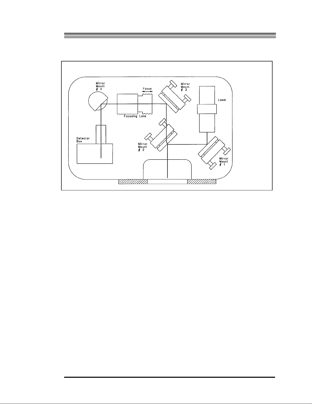
Design: Components and Function 2
The rotation monitor (Figure 2-13) is used to monitor and record the rotation
of the test mass during each drop. The rotation monitor consists of a rigid
anodized aluminum housing mounted on the top flange of the dropping
chamber, above the viewing port. The rotation monitor employs a very
sensitive optical lever system to measure and record the rotation of the test
mass which can be used as a means to reject bad drops or determine when the
mechanical system is not functioning properly. A diode laser produces a
visible beam which is directed onto and reflects from a mirror attached to the
top of the dropped object. The reflected beam is sent through a lens and is
focused onto a two axis position sensitive photodetector. This system rejects
translation and is only sensitive to rotation. The diode laser beam reflects off
mirror #1 and the beamsplitter (mirror mount #2). The beam then passes
down through the dropping chamber viewing port, where it reflects off a flat
mirror which is mounted to the top of the test mass. The return beam from
the test mass mirror passes through the beamsplitter and reflects off mirror
#3. The beam then passes through the 200 mm focusing lens, which is
adjusted to eliminate cross coupling of translations which would otherwise
appear as rotations. The beam is then reflected off mirror #4 and enters the
detector box. The output from the quad detector is used to provide rotation
information to the computer/system controller. Each rotation monitor is
calibrated by Micro-g Solutions to determine the rotation and translation
sensitivity. These data are used to calculate rotation errors. The rotation data
can also be displayed on the computer screen, and is recorded in the DDT
output data file.
2-22
Page 31
Design: Components and Function 2
Figure 2-13 Rotation Monitor
2-23
Page 32

Page 33

How to Set Up and Run the FG5 3
3. How to Set Up and Run the FG5
3.1. Setting Up the FG5
NOTE: These instructions are based on the assumption that all subsystems
of the FG5 are aligned correctly and operating properly. If adjustment or
alignment is necessary, consult chapter 4, “Adjustment and Maintenance”
for instructions, before proceeding with set up. When setting up the FG5,
it is helpful to use the FG5 Setup Checklist in Appendix D, page 9-4.
3.1.1.INTERFEROMETER
1. 1. Locate and mark a reference point on the floor where gravity will be
measured.
2. Lift the interferometer out of its shipping case by the handles on the sides
of the base.
THE INTERFEROMETER.
3. Lay the interferometer end with the telescope mount on the foam case
insert, and attach the three legs. It is best to use two people so one can
steady the interferometer while the other is attaching the legs. Carefully
raise the interferometer to its upright position and place on the floor.
Tighten each leg by sliding the steel rod through the hole in the leg and
turning until the legs are snug. There is no need to over-tighten the legs
since they experience no shock during the drop.
4. Remove the two dust caps from the top and telescope mount end of the
interferometer.
5. Position the interferometer over the reference mark by sighting down
through the beam splitter to the mark on the floor. Orient the
interferometer with the laser tube in a north-south direction, if possible, to
minimize Coriolis errors. Rotate the brass V-blocks at the bottom of the
interferometer legs so the V's in the leveling feet all point to the reference
mark on the floor. ! THE FLOOR SHOULD BE AS CLEAN, SMOOTH,
! DO NOT USE THE LASER AS A HANDLE TO LIFT
3-1
Page 34

How to Set Up and Run the FG5 3
AND LEVEL AS POSSIBLE. IT IS BEST TO SET UP THE FG5 ON A
CONCRETE OR HARD TILE FLOOR!
3.1.2.ELECTRONICS CASE
6. Place the electronics case in a convenient location within two meters of the
interferometer. It is helpful (if the site permits) to place the rack adjacent
to the connector end of the laser head with the front side of the rack facing
in the same direction as the beam blocker controls on the interferometer.
Place the computer/system controller on top of the electronics case.
7. Remove the front and rear covers of the electronics case. Remove the
cables from the pouch on the inside of the rear cover.
8. Check the input voltage settings and make sure they are set to the proper
AC line voltage. If the instrument is not set to the correct voltage see
appendix A for instructions on how to change the voltage selection..
9. Make sure the following switches are off:
• Main AC power (rear)
• Main DC power (rear)
• Laser power (main AC power and key switch)
• Universal Time Interval Counter
• Superspring coil
• Portable ion pump power supply (AC, BAT, and HV)
10. Connect the main AC power cable from the mains power input (rear of
electronics case) to the AC power receptacle.
11. Remove the laser control cable (#7) and laser HV cable (#6) from the
electronics case and connect them to the laser head.
12. Turn on the main AC and DC power switches on (rear of electronics case).
13. Turn on power to the laser. Consult the instructions below for the proper
laser.
3-2
Page 35

How to Set Up and Run the FG5 3
3.1.2.1.Model AL-1 Laser:
3.1.2.1.1.Warm Up
• Set the LOOP switch to the OPEN position.
• Turn the switch on the laser controller to MANUAL.
• DO NOT ADJUST THE COARSE GAIN KNOB.
• Turn on the main power switch and the key switch for the laser tube
HV. Both lights on the laser controller panel should come on.
• Set the heater current to 0.3 using the front panel monitor to view
current..
• Allow the laser to warm up for at least half an hour before locking.
3.1.2.1.2.Operation
• After the laser is warm, the LOOP switch should be closed.
• The control switch should be set to REMOTE so that the computer can
control the red/blue side-lock choice.
3-3
Page 36

How to Set Up and Run the FG5 3
3.1.2.2.WEO Model 100 Laser
• Turn on the power (main power and HV key switches).
• Select the proper iodine peak.
• Set the servo control to AUTO.
• Do not adjust any other controls. Nominal control settings are:
Signal Monitor Section:
Meter Select: 1F
Gain 1
Time Constant 1
Temperature Control Section:
Body Temp Mode OFF
Temperature Control Section
Meter BIAS
Bias Voltage Set to 0V (meter)
• Allow the laser to warm up for at least two hours (or until the
temperature of the laser has stabilized) before beginning observations.
3.1.3.DROPPING CHAMBER TRIPOD
14. Remove the tripod tray from the Superspring case and place it carefully
upside down on the floor.
15. Remove the three tripod legs from the dropping chamber case and attach
them to the tray.
16. Turn the tripod upright and tighten the legs by turning the large 3-lobe
knobs clockwise.
At this point the interferometer will be used to support the dropping
chamber tripod.
3-4
Page 37

How to Set Up and Run the FG5 3
ARE IN THE UP POSITION AND THE TOP DUST CAP HAS BEEN
REMOVED.
17. Slide each of the three horizontal alignment pins on the top of the
18. Open the three dropping chamber clamps on the tripod tray by turning
19. Carefully remove the dropping chamber from its case by the handles and
! MAKE SURE THE HANDLES ON THE INTERFEROMETER
interferometer radially outward by pulling the 5-lobe knobs until they
stop. Carefully position the tripod on top of the interferometer using the
single locating pin and the three horizontal alignment pins on the top of
the interferometer as a guide. The three brass V-posts in the bottom of the
tripod tray should fit over the pins on the interferometer. The handles on
the interferometer should be up and not touching the legs on the tripod.
the three 5-lobe knobs fully counterclockwise. The clamps must be
outside the mounting pocket so the dropping chamber can be placed on
the tripod.
gently place it into the pocket in the top of the tripod tray, allowing the
two vertical alignment pins in the tray to engage the sockets in the
dropping chamber base. Orient the dropping chamber so the ion pump is
on the side of the interferometer which is opposite the laser head, directly
above the beam blocker controls on the interferometer.
20. Lock the dropping chamber in place with the three clamps by turning the
5-lobe knobs fully clockwise. This rotates the dropping chamber clamps
in place over the base of the chamber. Make sure the laser beam coming
out of the dropper hits the floor on the reference mark.
21. Release the cart travel lock by turning the motor shaft slightly
counterclockwise with a 4 mm hex wrench or ball driver to release the
pressure on the travel lock mechanism. While holding this position, pull
out the brass knob, rotate it 90° in either direction, and gently release it so
the pin in the shaft rest in the lock. Gently release the wrench or ball
driver from the motor shaft
3-5
Page 38

How to Set Up and Run the FG5 3
3.1.4.ION PUMP
22. Recheck the AC,BAT, and HV switches on the ion pump power supply,
and make sure they are off.
23. Connect the ion pump HV cable (#9) to the ceramic connector on the
pump. Connect the small green safety ground umbilical of the HV cable
to one of the banana jacks located on the base of the dropping chamber
near one of the handles. Connect the safety HV ground (cable #10) to the
other banana jack on the base of the dropper. Tie both cables to a tripod
leg with a velcro strap.
24. If the vacuum in the dropping chamber has remained intact since the
previous use, the ion pump alone may be sufficient to pump down the
chamber. The ion pump will probably start if it has been off for two hours
or less.
25. Before turning on the ion pump, set the front panel meter select knob to
PUMP VOLTAGE (kV). Turn on the pump and check the meter. The
voltage should be at least 2 kV within 5 minutes after turning on the ion
pump. An increasing voltage usually indicates that the ion pump is
starting. Nominal voltages (at operating pressure) are:
4 kV on AC
3 kV on battery power
26. If the ion pump does not start within 5 minutes, shut off the power at the
ion pump power supply, and prepare to rough-pump the dropping
chamber with the turbo pump. See appendix B for instructions.
3-6
Page 39

How to Set Up and Run the FG5 3
3.1.5.ROUGH LEVELING
INTERFEROMETER
Note: While leveling the interferometer and dropping chamber tripod, note
that turning the tripod feet clockwise lowers the dropping chamber tripod
and turning the interferometer feet clockwise raises the interferometer.
27. Adjust the interferometer base legs until the bubble levels mounted on the
tripod base are centered. For this step, and following steps concerning
leveling, be sure to center the cross level first, then the long level. The
cross level is the one which is perpendicular to the laser head axis and the
long level is parallel to the laser head axis. If the long level is adjusted
first, it will change when the cross level is adjusted. When the cross level
is adjusted first, it does not change when the long level is adjusted.
28. Remove the blue pads and brass tripod feet from the Superspring case.
Make sure the pads are clean.
29. Place a tripod foot under each leg of the tripod. Raise each foot and slide
a blue pad under the foot.
30. Center the cone in each foot under the nylon ball on the end of each tripod
leg. Turn the leveling adjustment screws on the feet counterclockwise,
raising them until they just contact the balls. It is important that there is
no horizontal tension between the feet and the tripod leg because it will
cause the dropping chamber to shift sideways when it is lifted. It is
helpful to rotate the foot slightly (while it is in contact with the nylon ball)
to release any horizontal tension.
3-7
Page 40

How to Set Up and Run the FG5 3
3.1.6.DROPPER VERTICALITY
31. After each foot is in contact with the tripod leg, rotate each tripod foot
leveling screw exactly one revolution (counterclockwise), using the mark
on the top of the adjustment screw as a reference. This raises the tripod
off the interferometer just enough to take the weight of the tripod and
dropping chamber off the alignment pins.
32. Level the tripod tray by adjusting the tripod feet (not the interferometer
base legs. Be sure to adjust the cross level first, then the long level (see
step 27 for explanation). It is best to adjust the levels by raising the proper
adjustment foot. This will prevent the dropping chamber from contacting
the interferometer.
33. Gently slide each alignment pin in until it reaches its stop. If any of the
three alignment pins do not slide freely, the tripod is still in contact with
the interferometer. If this happens, slide the alignment pins out, and
lower the tripod leveling feet (turning clockwise) until the cones are no
longer in contact with the tripod leg balls. Return to step 30 and repeat
steps 30-33 to raise the tripod.
THERE MUST BE NO CONTACT BETWEEN THE
!
TRIPOD/DROPPING CHAMBER ASSEMBLY AND THE
INTERFEROMETER DURING OPERATION. THIS ALSO APPLIES TO
CABLES. CABLES CONNECTED TO THE INTERFEROMETER MUST NOT
TOUCH THE DROPPING CHAMBER/TRIPOD, AND CABLES
CONNECTED TO THE DROPPING CHAMBER/TRIPOD MUST NOT
TOUCH THE INTERFEROMETER.
3.1.7.BEAM VERTICALITY
34. Make sure the plug in the side of the interferometer base has been
removed. Remove the collimating telescope from the Superspring case
and take off the lens cap. Slide the telescope onto the dovetail at the end
of the interferometer base until it reaches its stop and tighten the three
screws on the bottom of the mount.
3-8
Page 41

How to Set Up and Run the FG5 3
35. With both beam blockers pushed in, look through the telescope and focus
the crosshairs with the telescope by rotating the eyepiece. It may be
helpful to place a white card in front of the telescope to see the crosshairs
better.
COLLIMATING TELESCOPE (adjust only the eyepiece). THE OPERATOR
WHO FOCUSES THE CROSSHAIRS SHOULD ALSO PERFORM THE
REMAINING ALIGNMENT STEPS (36-39).
36. Pull out the reference beam blocker and adjust the mirror mount in front
! DO NOT ADJUST THE INFINITY FOCUS OF THE
of the telescope to center the reference beam on the crosshairs.
3.1.8.VERTICAL ADJUSTMENT OF THE
TEST BEAM
37. Pull out the test beam blocker to view both the test and reference beams in
the telescope.
38. Perform a rough vertical adjustment of the test beam by turning the
adjustment screws at the bottom of the interferometer legs until the two
points are coincident in the telescope. This is most easily done by first
adjusting the interferometer leg nearest the telescope eyepiece (moving
the spot diagonally) until the test beam spot is on the vertical crosshair
which passes through the reference beam spot, either above or below it.
Then adjust the single leg on the side of the interferometer opposite the
telescope to move the test beam spot vertically up or down into
coincidence with the reference beam spot (centered on the crosshairs).
39. Align the test and reference beams precisely by blocking the reference
beam blocker and adjusting the interferometer legs until the test beam is
centered in the crosshairs of the telescope. Alternately block the test and
reference beams to verify that both beams are centered on the crosshairs,
then return both beam blockers to their out position.
40. Snap the top bellows ring off of its retainer and lower the bellows ring so
it rests on the Superspring mounting plate. This allows access to the
underside of the interferometer.
3-9
Page 42

How to Set Up and Run the FG5 3
3-10
Page 43
How to Set Up and Run the FG5 3
3.1.9.REFERENCE HEIGHT
41. Hang the measuring scale from the Superspring mounting ring under the
interferometer base. Loosen the clamp and slide the scale down until it
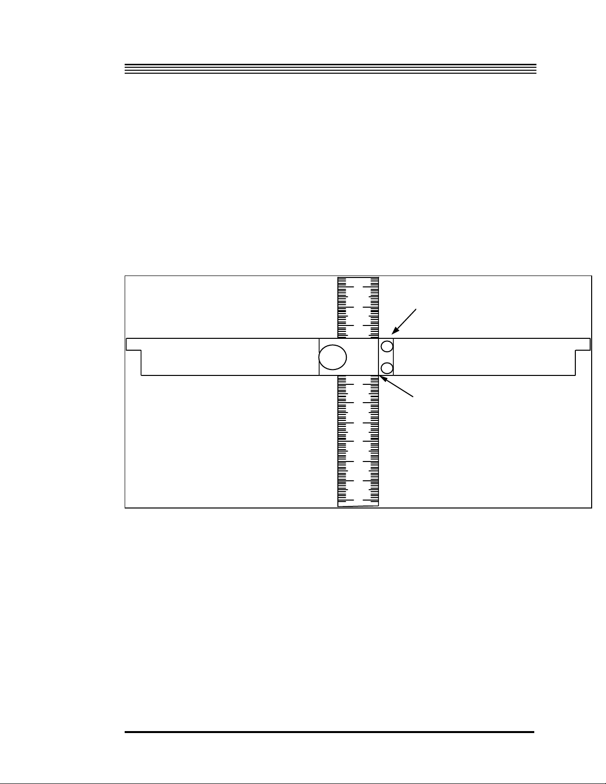
touches the floor, then clamp it in place. Make sure the scale is straight.
Read the value at the bottom side of the clamp (Figure 3-1). This value is
nominally 495 to 510 mm. Record the value (cm) for later entry in the
system check log.
Clamp
Note this Value
Figure 3-1 Measuring Scale
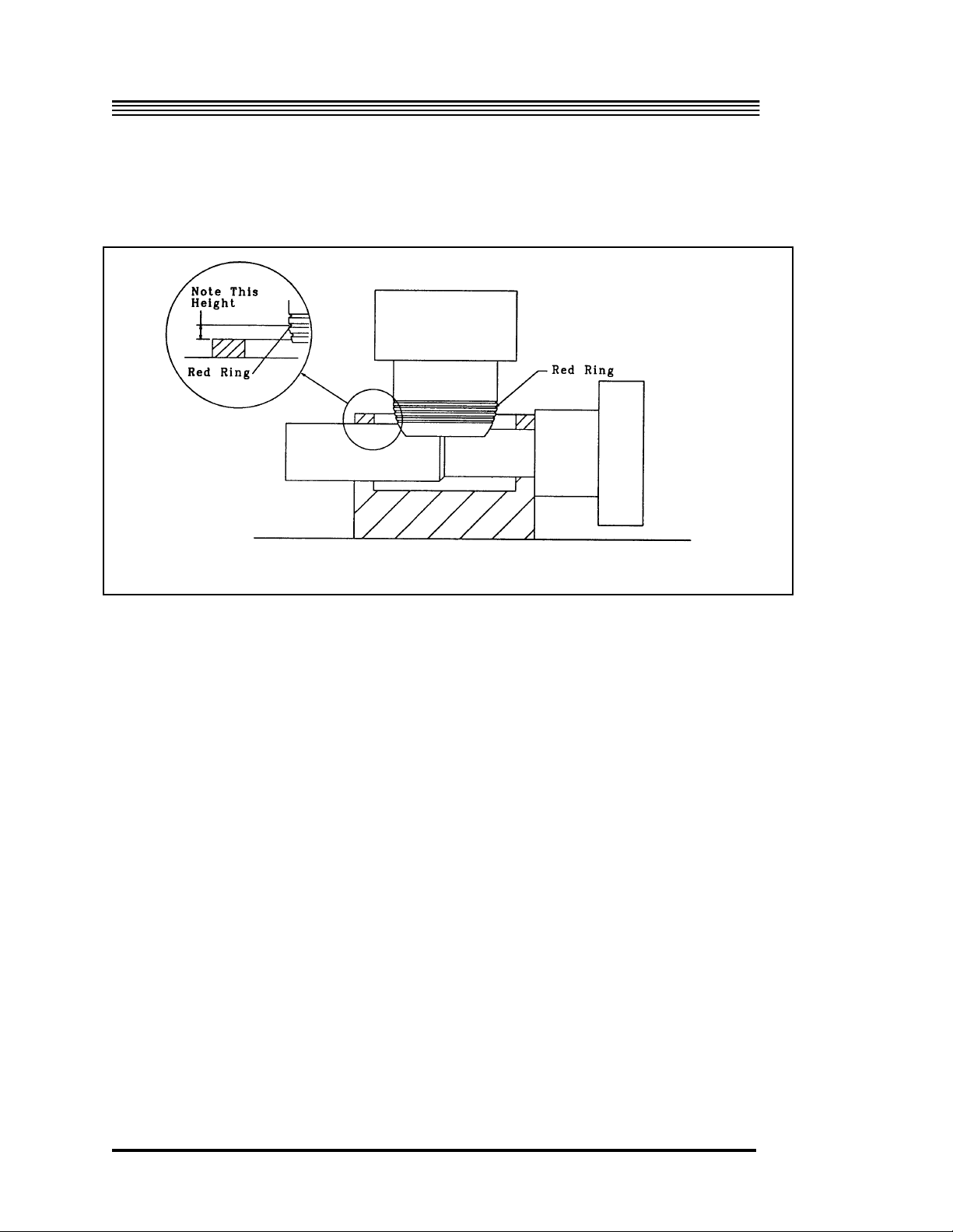
42. The brass V-posts on the bottom of the tripod are marked with concentric
rings 1 mm apart, the red ring being 0 (see Figure 3-2). Estimate the
distance the tripod has moved upward (+) or downward (-) and add this
to the value read with the scale. If our setup procedure has been followed
correctly, the dropping chamber will be 1 ring (1 mm) above the zero
position. Record this value (the Superspring reference height added to the
vertical distance indicated by the brass V-posts in cm) in the system check
log as the reference height. It must be entered in the FG5COMND.DAT
file before beginning observations. Consult the FG5 Software Manual for
instructions.
3-11
Page 44
How to Set Up and Run the FG5 3
Figure 3-2 V-Post
3-12
Page 45

How to Set Up and Run the FG5 3
3.1.10.THE SUPERSPRING
43. Remove the dust cap from the top window of the Superspring. Make sure
the Superspring locking mechanism is engaged. Then carefully slide the
Superspring under the interferometer base. The top Superspring flange
has three “ears”. Note that the ear which is directly above the travel lock
is larger than the other two to ensure correct orientation of the
Superspring. The Superspring mounting plate has openings for the ears
(one larger than the other two) to ensure proper orientation of the
Superspring. The large ear is oriented toward the leg of the interferometer
which is farther from the telescope. Gently lift the Superspring until the
top flange is above the mounting plate. Rotate the Superspring until the
ears are directly above the nearest leveling screws, then gently lower the
Superspring into place so the v-grooves on the underside of the ears are
resting on the leveling screws.
SUPERSPRING TOP FLANGE ARE CORRECTLY SEATED ON THE
ADJUSTMENT SCREWS. CHECK THAT EACH V-GROOVE IS ENGAGED
IN EACH LEVELLING SCREW. IT IS VERY EASY FOR ONE LEVELLING
SCREW TO RIDE UP ON THE SIDE OF ITS V-GROOVE.
44. Make sure the COIL switch on the Superspring controller is OFF. Connect
SWITCH IS ON.
45. Adjust the three leveling screws to level the Superspring with the two
! VERIFY THAT THE THREE V-GROOVES IN THE
the Superspring control cable (#15) from the rear (power supply panel) on
the electronics rack (yellow washer) to the connector on the base of the
Superspring.
! DO NOT ATTACH CABLE 15 WHILE THE WHEN THE COIL
precision level vials on the base. The levels should be nearly centered. If
they are not, recheck the v-grooves, and make sure they are properly
seated on the adjustment screws.
3-13
Page 46

How to Set Up and Run the FG5 3
THEMSELVES. They are preset to provide the correct internal vertical
reference for the Superspring.
! CAUTION: DO NOT ADJUST THE LEVELING VIALS
3.1.11.TRAVEL LOCK
46. Release the Superspring travel lock by pulling out the brass travel lock
knob until it engages the shaft and slowly rotating it counterclockwise
until it reaches the stop (190°). Slowly release the lock knob. The arrow
on the lock knob points down when it is locked (up when it is unlocked).
47. If necessary, one can use the travel lock knob dampen excess spring
motion. Carefully pull the knob out, and slowly turn it clockwise until the
travel lock just touches the spring support structure. Then slowly return
the knob to the unlocked position.
3.1.12.CONNECT REMAINING
SYSTEM CABLES
48. Attach the rest of the system cables as described below. Both ends of all
cables are labeled with the proper location for each connector. When
connecting cables to the computer, make sure the power is off.
• MAKE SURE THE DROPPING CHAMBER IS IN STANDBY (HIT
RESET BUTTON TO FORCE THE DROPPING CHAMBER
CONTROLLER INTO STANDBY). Connect the dropping chamber
signal cable (cable #14, white Lemo connector) from the rear (power
supply panel) of the electronics rack to the electrical feedthrough on
the service ring.
• Connect the rotary shaft encoder cable (cable #13, blue Lemo
connector) from the rear (power supply panel) of the electronics rack
to the blue Lemo connector on the motor drive assembly.
3-14
Page 47

How to Set Up and Run the FG5 3
• Connect the DC motor power cable (cable #12, orange Lemo
connector) from the rear (power supply panel) of the electronics rack
to the orange Lemo connector on the motor drive assembly.
• Connect the APD power cable to the interferometer base and the
power supply.
• Connect the APD fringe cable to the interferometer TTL and the
SCALER COUNTER Input Fringes.
• Connect the 37 pin PIO cable to computer
• Connect the IEEE cable to computer
• If the FG5 is equipped with the environmental sensors package,
connect the 9 pin barometer cable to computer.
• Connect the temperature cable from the temperature probe to the BNC
16 (1F).
49. Recheck the verticality of the interferometer by placing the alcohol pool on
the top of the Superspring. Level the interferometer, if necessary, by
adjusting the tripod feet.
50. If adjustments were made in step 51, recheck the alignment pins to assure
that there is no contact between the dropping chamber and the
interferometer.
3-15
Page 48

How to Set Up and Run the FG5 3
3.1.13.SUPERSPRING ZERO-
POSITIONING
51. Allow the spring to settle for at least two minutes before setting the zeroposition of the mainspring. Use the d.c. motor to move the top of the
mainspring relative to the inner support structure. The zero-position is
monitored on the front panel BNC of the Superspring controller marked
SPHERE OUT. The position can be adjusted manually or automatically to
be within about ±20 mV of 0 V. It is preferable to set the zero-position
between 0 mV and +20 mV since long term drift will normally be
downward (negative).
The rotary knob on the front panel can be set to MANUAL, WINDOW,
AUTO, or REMOTE. The REMOTE setting should not be used. The
MANUAL setting allows the user to apply a voltage to the d.c. motor that
can be varied with a front panel mounted trimpot labeled MOTOR. The
middle of the trimpot (marked 5) applies no voltage. Numbers above the
middle (5-10) cause the motor to lift the mass (increasing positive voltage
on the sphere BNC) and numbers below the middle (0-5) lower the mass
(Decreasing the voltage on the sphere BNC).
AUTO causes the motor to seek the zero-position automatically.
! NOTE: IN AUTO, THE DC MOTOR IS ALWAYS ACTIVE. THE
SUPERSPRING SHOULD NOT BE LEFT IN AUTO DURING NORMAL
OPERATION (WHEN THE COIL SERVO IS ACTIVE)
The WINDOW setting turns on the motor only when the spring position is
out of range (indicated by an LED on the front panel). In this case, the
AUTO mode is activated until the position is moved to zero, and then the
motor is deactivated. The Superspring can be left in this condition, but it
is still advisable to turn the rotary knob to OFF before closing the
Superspring coil loop (switch set to CLOSED on the front panel).
WINDOW mode is currently not supported by the FG5 software.
3-16
Page 49

How to Set Up and Run the FG5 3
When setting the zero position, it is very important to make sure that the
mass is hanging freely, and is not out of range. A substantial variation in
SPHERE OUT voltage when the servo loop is open indicates that the mass
is hanging freely. It is possible for the mass to be out of range of the
detector. In this case, a small positive or negative voltage indicates that
the mass is above or below the detector, respectively. This can happen if
there is a large change in gravity (usually as a result of a large latitude
and/or elevation change) from one site to the next. The zero position can
be set by using the AUTO mode, which will move the mass to the zero
position. One can also move the test mass position using the MANUAL
mode. Before switching to MANUAL mode, first set the trim-pot to move
the motor in the correct direction. The trim-pot should be set above 5 if
the SPHERE voltage is negative or below 5 if the SPHERE voltage is
positive.
52. Once the desired zero-position is reached, (SPHERE output between 020mV) deactivate the motor by turning the front panel knob to OFF. The
spring should again be allowed to settle down for at least two minutes.
Set the coil switch to ON. This switch activates the Superspring main
servo loop for normal operation. At this point, there may still be a
rotation in the test mass( three second period) which is not damped by the
servo. This rotation mode will eventually damp out, and the gravity data
will be become quieter over the first hour.
3.1.14.FRINGE OPTIMIZING
53. To optimize the fringe signal, the test and reference beams must be made
perfectly coincident. The two interfering beams should be perfectly
overlapped and also have no angular deviation for the greatest signal.
The translation of the test beam relative to the reference beam is done by
adjusting the translator plate (sometimes called twiddler). The angular
deviation is minimized by adjusting mirror mount #6 of the
interferometer.
54. Adjust mirror #6, if necessary, until the beams are coincident in the
telescope. Then, move the translator plate (twiddler) until they are
3-17
Page 50

How to Set Up and Run the FG5 3
coincident in the viewing periscope. Adjustment of the translator plate
does not affect the appearance of the beams in the telescope.
55. If the two beams can be overlapped using the twiddler, skip to step 58. If
the translator plate does not have enough range to make both beams
coincident, there are two methods of adjustment. The simplest adjustment
is made using mirror #6 to translate the test beam horizontally. If a
vertical adjustment is needed, the Superspring position must be adjusted
by loosening and translating the interface plate between the
interferometer base and the Superspring. These adjustments are not
normally required, and may indicate a problem.
56. Vertical coarse adjustment of the test beam in the fringe viewer: Move the
translator plate (twiddler) to the center of its travel so that the glass is
normal to the test beam. Adjust all three screws of mirror mount #6
equally in or out to move the beam left or right in the periscope. View the
two spots in the telescope while adjusting the screws. Adjust the screws
individually until the beams are coincident in the telescope, then adjust
the beam translator until both beams are coincident in the periscope.
Note: Only the horizontal axis in the periscope can be made coincident
using mirror mount 6. Vertical coincidence must be accomplished with
the translator plate or using step 57 for a coarse adjustment.
57. Horizontal coarse adjustment of the test beam in the fringe viewer: If the
twiddler is not sufficient to move the test beam vertically to overlap with
the reference beam in the fringe viewer the Superspring location relative
to the interferometer base must be adjusted. This is accomplished by
translating the interface plate which is attached to the interferometer base
and supports the Superspring. First, loosen (but do not remove) the bolts
that fasten the interface plate to the interferometer. It is usually sufficient
to loosen each bolt by ¼ turn. Then suspend and level the Superspring.
Unlock the Superspring and translate the interface plate so that the test
beam and reference beams overlap in the fringe viewer. Make sure that
the twiddler is set so that the glass is normal to the laser beam. After the
beams are overlapped, tighten the bolts that fasten the interface plate to
the interferometer plate.
58. Connect the ANALOG output on the interferometer (near the beam
blockers) to an oscilloscope, with the following settings:
Scale = 50 mV/div
3-18
Page 51

How to Set Up and Run the FG5 3
Sweep = 2 µsec/div
AC coupled input
59. Make sure the laser is locked. Set the dropper to OSC mode and press
RESET, then INIT. This moves the cart slowly up and down at a constant
velocity and produces a constant frequency fringe signal which is useful
for adjusting mirror #6.
60. Adjust mirror #6 until the peak-to-peak signal is maximized on the
oscilloscope. Also adjust the twiddler for maximum signal. Record this
amplitude in the system check log.
3.1.15.Dropper Controller
61. OSC mode can be terminated by hitting RESET on the dropping chamber
controller. This turns off the motor and lets the cart drop to the bottom. It
is preferable to wait until the cart is near the bottom before hitting RESET.
Make sure the cart is resting at its bottom position, and the red STANDBY
light is on. Set the trigger source switch to EXT, and turn the rotary knob
to AUTO. Press RESET, then INIT. The dropper is now waiting for an
external signal from the computer to initiate a drop.
3.2. Running the FG5
The FG5 begins observations when the realtime data program, OLIVIA, is
executed. Consult the FG5 Software Manual for instructions on operating the
program. The software manual also includes information about software
features, gravity corrections, output displays, and input/output file
descriptions, as well as data analysis and trouble shooting.
3.2.1.SYSTEM CONTROLLER SETUP
3-19
Page 52

How to Set Up and Run the FG5 3
1. Make sure the time and date are correctly set to UT. This is done by
entering TIME and DATE at the DOS prompt.
2. Edit the FG5COMND.DAT file and make the following entries:
• Site name (C01) and site code (C02)
• Site coordinates (C03 and C04) and elevation (C07)
• Measured reference height (C05)
• Nominal air pressure (C08)
• Gravity gradient (C10)
• Polar motion X and Y components (C12)
• Session scenario (C14-C19)
• Output control codes and filenames (C56-C61)
3. Check the FG5PARAM.DAT file, and make changes, if necessary.
4. If peak detection is enabled (P32), check the 1f signals and correct, if
necessary.
NOTE: Make sure the laser is warm and the meter select switch of the
WEO Model 100 laser controller is set to 1f (see WEO manual). After
reading the 1f signals, be sure to reconnect the BNC cable between the
signal monitor connector on the laser controller and channel 4H of the
IO/TECH BNC 16.
3.2.2.PROGRAM SETUP
5. Begin observations by executing the OLIVIA program. Refer to the FG5
Software Manual for instructions.
3.3. Shutting Down the FG5
3.3.1.COMPUTER
3-20
Page 53

How to Set Up and Run the FG5 3
1. Backup the data.
2. Shut off computer power.
3-21
Page 54

How to Set Up and Run the FG5 3
3.3.2.SUPERSPRING
3. Set the switch on the front panel of the Superspring controller to OPEN.
4. Engage the Superspring travel lock. The arrow on the lock know points
down when it is locked and up when it is unlocked.
5. Disconnect the cable from Superspring electronics.
3.3.3.INTERFEROMETER
3.3.3.1.OPTION 1: Model AL-1 Laser.
6.
a) Set the switch on the front panel of the laser controller to MANUAL.
b) Turn the fine gain control off (fully counterclockwise).
c) Set LOOP switch to OPEN.
d) Turn the key switch off. The green indicator light should turn off.
e) Turn power switch off.
3.3.3.2.OPTION 2: WEO Model 100 Laser
6.
a) Set servo control to OFF (recommended but not required).
b) Turn the key switch off. The green indicator light should turn off.
c) Turn power switch off.
3-22
Page 55

How to Set Up and Run the FG5 3
3.3.4.DROPPING CHAMBER
7. Press RESET on dropper controller.
8. Disconnect the shaft encoder, motor power, and cart control cables from
the dropping chamber.
9. Engage the dropping chamber travel lock.
3.3.5.POWER
10. Turn off the UTIC and any other devices that are still on.
11. Turn off the AC and DC power (rear of electronics rack).
3.4. Disassembling and Packing the FG5
NOTE: Please follow these instructions carefully. Care in packing the
components properly will result in easier and faster set-up in the field, and
will help protect the instrument from damage.
3.4.1.ELECTRONICS:
Unplug cables from the electronics rack and components.
1. APD power cable
2. TTL fringe BNC cable
3. Laser signal cable
4. Laser HV BNC cable
5. Temperature monitor BNC cable
6. AC Mains power cord
7. AC computer power cord
3-23
Page 56

How to Set Up and Run the FG5 3
The following cables may be disconnected from exterior components and
remain connected to the electronics case. They are rolled up and stored inside
the electronic case during shipment.
8. Ion pump HV supply cable
9. Ion pump supply safety ground cable
10. GPIB cable to computer
11. PIO cable to computer
12. Put the remaining cables in the zippered pouch which is attached to the
inside of the rear electronics case lid.
3.4.2.SYSTEM CONTROLLER
13. Unplug power cords and printer cable from the computer and printer and
place in the system controller case.
14. Close computer lid and place computer/docking station in the system
controller case.
15. Close the system controller case and secure all latches.
3.4.3.ROTATION MONITOR (IF
INCLUDED)
16. Unplug all BNC and power cables from the rotation monitor, detector box,
and electronics rack and store in the rotation monitor case.
17. Remove the rotation monitor from the dropping chamber (two M6x35
screws) and place in the rotation monitor case.
18. Close the rotation monitor case and secure all latches.
19. Replace the two M6x35 screws in the dropping chamber top flange, and
replace the viewing port cover.
20. Secure the lids to the electronics case.
3-24
Page 57

How to Set Up and Run the FG5 3
3.4.4.DROPPING CHAMBER
21. Lock the cart by turning the locking hub counterclockwise using a 4 mm
Allen wrench or ball driver until the cart stops moving.
22. Pull and rotate travel lock knob 90°, allowing the pin to drop onto the hub,
then rotate the lock clockwise until the pin engages the hub.
23. Open the three dropping chamber clamps by turning the
24. 5-lobe knobs fully counterclockwise so the clamps are outside the bottom
flange of the dropping chamber.
25. Lift the chamber off the tripod and set it in its case.
3.4.5.TRIPOD
26. Carefully remove the tripod from the interferometer base. Remove the
legs from the tripod. Place the legs in the dropping chamber case and the
tripod tray in the Superspring case (large 3-lobe knobs toward the outside
of the case).
27. Place the brass tripod feet in the Superspring case and the blue pads in the
dropping chamber case.
28. Close dropping chamber case and secure all latches.
3.4.6.SUPERSPRING
29. Pull out the travel lock brass knob until it engages the locking mechanism,
and rotate the lock 190° clockwise to lock it in place. The arrow on the
lock knob points down when it is locked and up when it is unlocked.
30. Remove the Superspring from the interferometer base. Insert the plug in
the top of the Superspring and set the Superspring in its case.
3-25
Page 58

How to Set Up and Run the FG5 3
3.4.7.INTERFEROMETER
31. Loosen the three locking screws of the telescope rail assembly. Slide the
assembly off the interferometer base and place it in the Superspring case.
Make sure the lens cap of the telescope is in place.
32. Close Superspring case and secure all latches.
33. Insert plugs into the top and side of the interferometer base.
34. Remove the legs from the interferometer. This is best done by two people.
Gently place the interferometer on the telescope end (legs horizontal) on
the bottom part of the interferometer case or another padded surface. One
person should steady the interferometer while the other person unscrews
the legs.
35. Place the legs in bottom of the interferometer case and cover with the
foam pad provided.
36. Gently place interferometer base in the case above the legs.
37. Fold the handles down on the interferometer base.
38. Close interferometer case and secure all latches.
3.4.8.TURBO PUMP (IF USED)
39. Make sure the blank flange is in place on the turbo pump intake flange.
40. Make sure all covers are in place on the flexible tube and turbo pump
exhaust flange.
41. Unplug the power cord from the turbo pump.
42. Store the power cord and flexible tube in the base of the turbo pump case.
43. Place the turbo pump in the turbo pump case.
44. Close the turbo pump case and secure all latches.
3-26
Page 59

Adjustment and Maintenance 4
4. Adjustment and Maintenance
NOTE:
wherever possible. However, some “off-the-shelf” purchased components
use English screws and dimensions.
The FG5 has been engineered to use metric screws and dimensions
4.1. The Dropping Chamber
4.1.1.REPLACEMENTS AND
ADJUSTMENTS
4.1.1.1.Removing The Dropping Chamber Cover
When opening the dropping chamber, take great care not to contaminate the
inside surface of the chamber cover or any of the interior parts. Always wear
clean-room gloves when handling internal parts. If any of the parts are
contaminated, clean the part using accepted vacuum system cleaning
procedures before reassembly. When performing repairs in the field, it is
sufficient to wipe or flush the contaminated parts with alcohol. Whenever
possible, vent the chamber with dry nitrogen rather than air. This will reduce
the pump down time after the chamber is reassembled.
To vent the dropping chamber, remove the clamp and blank flange from the
vacuum valve on the service ring. Loosen the vacuum valve lock ring and
slowly open the valve by rotating the control knob, allowing the chamber to
return to atmospheric pressure. It is best to vent using dry nitrogen, but it
can be directly vented to air. In any case, try to ensure that the gas entering
the chamber is free of particulate matter.
Remove the six screws holding the top flange to the top of the dropping
chamber cover, and remove the flange. Loosen the four snubber lock nuts
4-1
Page 60

Adjustment and Maintenance 4
and back out the screws which position the top ring of the dropping
mechanism within the chamber cover. Remove the six screws holding the
chamber cover and handles to the service ring, and carefully lift the cover up
over the dropping mechanism. Be sure to protect the O-ring surface on the
exposed bottom flange of the chamber cover, and keep the flange clean.
4.1.1.2.Replacing the Dropping Chamber Cover
Inspect the chamber O-ring and sealing surfaces. Coat the O-rings with a very
light film of Apiezon L grease, if necessary, and re-install the chamber cover
and lifting handles. Tighten the mounting screws in a star pattern.
With the chamber cover mounted, rotate the four snubber screws on the top
rod ring out until they come in contact with the inside of the chamber cover
walls. Tighten the screws equally an additional 1/8 turn and lock in position
with the locking nuts.
Inspect the top flange O-ring and sealing surfaces. Coat the O-rings with a
very light film of Apiezon L grease, if necessary, and mount the top flange to
the chamber cover.
NOTE: Whenever the chamber cover is removed or the support snubbers of
the top rod ring are adjusted, the vertical alignment of the dropping chamber
must be checked and the level bubbles on the tripod tray must be reset. See
the section on “Leveling the Dropper”.
4.1.1.3.Replacing the Drive Belt
Follow the procedures described previously for removing the dropping
chamber cover.
Loosen the belt tension with the tension adjustment set screw located above
the top pulley assembly on the top rod ring. The belt is clamped to the back
4-2
Page 61

Adjustment and Maintenance 4
of the cart with two socket head screws. Remove the clamp and slide the
ends of the belt off the dowel pin. Remove the belt.
Before installing a new belt, clean both of the pulleys with acetone or alcohol
on a cotton swab. Wipe the new belt with acetone or alcohol to remove any
traces of oil or fingerprints.
Thread new belt around upper and lower pulleys, and place ends over the
dowel pin. A wire with a small hook works well to assist in threading the
belt around the lower drive pulley.
Replace belt clamp, but do not fully tighten. Tension belt while manually
moving the cart up and down to allow the belt to locate its natural position on
the pulleys, then tighten the belt clamp screws.
NOTE: The drive belt may not run exactly in the center of the pulley. This is
normal, but there should be a minimum clearance of 1 mm between the belt
and the side walls of the pulley housing (yoke).
4.1.1.4.Adjusting the Drive Belt Tension
Adjust belt tension using the set screw on the top pulley assembly, located on
the top rod ring. Tighten the belt adjustment screw until the slack has been
taken out and the belt is straight. Then tension the belt by tightening the
screw approximately three turns. If you are uncertain of the proper tension,
the screw can be tightened until the tension spring is just short of coil bind.
The belt can also be tensioned using the torque required to slip the pulley on
the belt to determine belt tension. Use a torque wrench to manually drive the
motor shaft (drive assembly). Tighten the set screw until the belt slips on the
pulley at a minimum of 6 inch-lb. when rotated into the lower stop.
4.1.1.5.Replacing the Ferrofluidic Vacuum Feedthrough
The chamber must be vented and opened for this procedure. If possible, use
dry nitrogen to vent the chamber.
4-3
Page 62

Adjustment and Maintenance 4
Loosen the English 4-40 clamp screws on the Helical coupling between the
motor and the Ferrofluidic vacuum feedthrough by reaching through the
access hole in the motor mount. Remove the three ¼-28 English screws which
attach the motor mount to the Conflat vacuum flange on the service ring.
Remove the motor mount assembly (including motor, Helical coupling, travel
lock plate, and encoder) from the Conflat vacuum flange, leaving the Conflat
flange and Ferrofluidic vacuum feedthrough attached to the service ring.
Inside the service ring, loosen the socket head clamp screw on the Helical
shaft coupler where it attaches to the lower drive pulley shaft. Remove the
three remaining Conflat mounting screws. Remove the Conflat with
Ferrofluidic feedthrough attached.
Remove the Helical coupling from the feedthrough, and unscrew the
feedthrough from the Conflat flange.
Lubricate the O-ring on the new Ferrofluidic vacuum feedthrough with a
light coat of Apiezon L grease. Use pliers with padded jaws (e.g. blue pad) to
gently tighten the feedthrough to the Conflat flange.
Reverse the procedure for reassembly.
4.1.1.6.Replacing the V-Plate
The V-plate contains three tungsten V's which support the test mass. Since
removal and insertion of the tungsten V's in the V-plate requires special tools,
this cannot be done in the field. However, an entire new V-plate assembly
can be installed. The dropping chamber must be vented and opened for this
procedure. If possible, use dry nitrogen to vent the chamber.
Remove the bottom drag-free cover from the cart by removing the three M3
screws. Detach the LED bracket from the side of the cart and pull it out of the
way, being careful not to detach or damage the wires connected to it.
Remove the two M3 screws and the threaded post attaching the top drag-free
4-4
Page 63

Adjustment and Maintenance 4
cover to the cart, observing the position of the post. Gently lift the cover off,
being careful not to damage the wires connected to it.
To remove the V-plate, the test mass must be partially disassembled. First,
note the orientation of the top part of the test mass and the V-plate. It is very
important to replace these parts in the same orientation. Remove the three
beryllium copper M3 screws that secure the top part of the test mass to the
three posts which pass through the V-plate. Now the lower portion of the
mass can be lowered through the V-plate. Remove the six M2 screws holding
the V-plate to the cart.
Reverse the procedure to replace the plate.
The tungsten balls from which the test mass is held are part of the top hat
assembly. If these balls need replacement, send the entire mass assembly to
Micro-g Solutions for installation and rebalancing. Reassemble the test mass
using the three beryllium copper M3 screws, and pack it carefully before
shipping. All the pieces must be included for the balancing to be done
correctly.
4.1.1.7.Replacing the Linear Bearings
The chamber must be vented and opened for this procedure. If possible, use
dry nitrogen to vent the chamber.
Remove the drive belt as described previously. Loosen the three M6 screws
in the split clamps on the top rod ring and remove the top rod ring.
Remove the upper bumper stop assembly from the rod by removing both
retaining rings from the rod. Remove the ribbon cable wires connected to the
cart. Remove the ribbon cable clamp on the cart, and gently lift the cart off
the guide rods.
4-5
Page 64
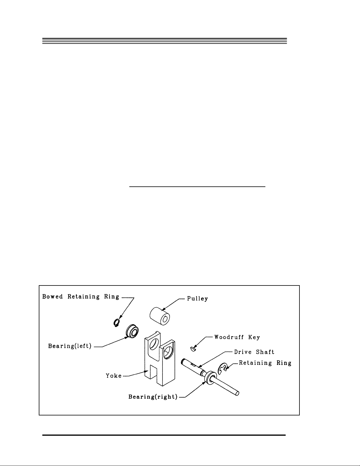
Adjustment and Maintenance 4
Two retaining rings secure each bearing to the cart. To remove the rings, they
must be wound off the end of each bearing. Slide the linear bearings out of
the cart and slide the new ones in. Replace the retaining rings.
NOTE: Venting holes have been added to the linear bearings by Micro-g
Solutions. In addition, the normal bearing lubricant has been replaced by a
special low vapor pressure oil (Krytox 143AC).
Reverse the above procedure to replace the cart.
4.1.1.8.Replacing the Shaft Bearings—Drive Pulley
Refer to Figure 4-1, Drive pulley assembly. Remove the drive belt as
described previously. Disconnect the Helical coupling between the pulley
shaft and the ferrofluidic vacuum feedthrough. Remove the five screws
holding the bottom rod ring to the bottom flange. Rotate the guide rod
structure so that the shaft clears the service ring and lift the structure.
Remove the two screws which fasten the pulley yoke to the bottom rod ring
and remove the yoke. Remove the bowed retaining ring from the short end
of the pulley shaft, noting the orientation of the bow.
4-6
Page 65

Adjustment and Maintenance 4
Figure 4-1
Drive Pulley Assembly
!CAUTION: DO NOT DEFORM THE BOWED RETAINING RING.
Remove the retaining ring from the other end of the shaft. Slide out the
pulley shaft, taking care not to lose the Woodruff key, and remove the pulley
from the bearing mounting yoke. Push the bearings out of the yoke.
Reassemble in reverse order. When reassembling the pulley shaft, be sure
that the bowed snap ring is seated fully in its groove.
NOTE: Pulley bearings are specially lubricated with Krytox LVP vacuum
grease.
4.1.1.9.Replacing the Shaft Bearings—Top Pulley
The procedure for the top pulley is similar to the drive pulley, except that
there is no Helical coupling and no Woodruff key. To access the top pulley
assembly, remove snap rings on upper bump stop and slide down shaft.
Remove two small retaining rings on top of upper pulley yoke and slide
pulley down to remove.
Reverse procedure for replacement of upper pulley assembly.
When reassembling the pulley shaft, be sure that the bowed snap ring is
seated fully in its groove.
4.1.1.10.Replacing the Rotary Shaft Encoder
Insert a 1/32" Allen wrench into the access hole at the top right (1 o'clock
position) of the encoder. Rotate the shaft until the set screw that holds the
disk to the shaft is aligned with the wrench, and loosen the screw. Pry the
4-7
Page 66

Adjustment and Maintenance 4
main encoder housing off the encoder back plate with a flat blade
screwdriver. The back plate must remain attached to the travel lock plate
with three screws to maintain proper alignment.
To reassemble, snap the new encoder over the encoder back plate, which was
left attached to the travel lock plate. Tighten the set screw and remove the
Allen wrench from its hole. Rotate shaft to check that the encoder disk is
rotating freely inside the encoder. Loosen and retighten set screw, if
necessary, until the disk rotates freely.
4.1.1.11.Pumping Down the Dropping Chamber
See Appendix B for instructions on pumping down the dropping chamber.
4-8
Page 67

Adjustment and Maintenance 4
4.2. The Interferometer
4.2.1.TROUBLESHOOTING THE BEAM
PATH
Periodic adjustments of the beam path can be made with the mirrors. (For a
detailed description of the beam path, see Chapter 2). Adjustments of the
beam path through the beam expander and the beam splitter assemblies are
performed separately.
The beam should pass through the center of the isolator without being
clipped by mirror mounts 1 or 2. The beam should pass through the center of
both the microscope objective and the collimating lens. After it exits the
collimating lens, the beam should be collimated approximately 5-7 mm in
diameter. On a card or paper placed in its path, it should make a round
uniform spot..
The beam should hit the center of mirrors 3 and 4 without being clipped by
the button-head screws. It should then pass through both the dropping
chamber and the Superspring and return intact. The recombined beam
should be centered in the fringe viewer. It should also be focused and steered
onto the center of the APD.
4.2.2.ALIGNMENT
4.2.2.1.Laser
The AL-1 laser mounts to the interferometer base with four 1/4-20 socket
head screws. The WEO iodine-stabilized laser mounts using four M6 socket
head screws. Tightening or loosening the front lower screw requires use of a
short Allen socket wrench.
4.2.2.2.Standard Optical Isolator
4-9
Page 68

Adjustment and Maintenance 4
The standard optical isolator is attached to the interferometer base by two
screws in the bottom. The optical element has a preferred orientation with the
linear polarizer first. This can be tested by rotating the optical isolator. You
should notice that you can change the light level from very bright to very dim
by rotating the isolator. Normally you should rotate this until the feedback
into the laser is minimal.
4.2.2.3./2-Faraday Isolator combination
These elements are mounted to the interferometer base by two screws on the
bottom (identical to that with the standard isolator). These M4 screws have an
M3 socket head. The λ/2 plate is mounted in front of the Faraday isolator and
is used to rotate the linear polarized laser beam to match the polarizer in the
Faraday isolator. The λ/2 plate should be turned until the light going through
the Faraday isolator is maximized. The base of this mount has two screws on
the bottom with oversized through holes to allow a height and tilt adjustment
of the polar angle. There are also 2 screws on the top plate of the mount with
oversized through holes to allow adjustment of the azimuthal angle. These
are M3 screws which require a M2.5 socket head hex wrench. Note that there
is a 1.6 mm horizontal translation of the beam through the Faraday isolator.
4.2.2.4.Optical Isolator Replacement
To replace the standard isolator with the λ/2-Faraday Isolator, remove the
five M5 screws (with M4 hex socket heads) which secure the Superspring
interface plate to the underside of the interferometer base. This allows access
to the two screws which secure the isolator mounting block to the
interferometer base.
4.2.2.5.Adjusting mirrors 1 and 2-The first two mirrors
Remove the focus lens sleeve and collimating lens sleeve from the spatial
filter assembly. Insert the alignment pinholes into the two lens mounts in the
spatial filter (see Figure 4-2). The sleeves are held in by M4 screws with a M3
socket head. Steer the beam through the two alignment pinholes. This is
easiest if you use the first mirror (#1) to adjust the translation of the beam to
4-10
Page 69
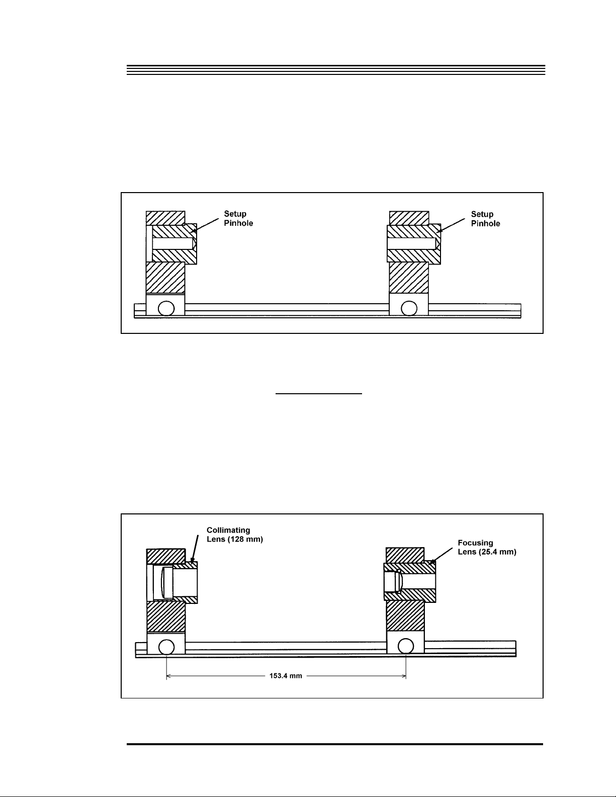
Adjustment and Maintenance 4
pass through the first pinhole and then use the second mirror (#2) to adjust
the beam angle so that it passes through the second (furthest) pinhole. This
procedure may require several iterations to get the alignment perfect.
Figure 4-2 Beam expander with alignment pinholes mounted
4.2.2.6.Beam Expander
4.2.2.6.1.Focusing lens:
Remove the alignment pinholes and put the focusing lens (25.4 mm focal
length) into the first lens holder. The lens should be inserted so that curved
surface is towards the input beam (Figure 4-3).
4-11
Page 70

Adjustment and Maintenance 4
Figure 4-3
Insert the collimating lens (128mm focal length) into the mount and adjust the
position of the lens to be about 153.4mm from the optical center of the
focusing lens. Look through the telescope at the spot and minimize the
diameter of the spot in the telescope by moving the collimating lens back and
forth. It is important to make sure that the crosshairs are in focus for the
individual performing this alignment. It is critical that the telescope has
already been adjusted for infinity focus using an autocollimation technique
and locked in place.
Beam expander
4.2.2.6.2.Collimating lens:
4.2.2.7.Leveling the Tripod Tray
Now that the beam has been steered through the optical isolator and beam
expander, it remains to use mirrors #3 and #4 to steer the beam vertically off
of beamsplitter #1 through the dropping chamber. This adjustment will be
made assuming that the interferometer is referenced to the bubble levels in
the tripod tray. First, we must verify or set the tripod bubble levels so that
they are aligned with the cart travel inside the dropping chamber.
First re-install the top middle cover on the interferometer base (leave
the two end plates removed for access). Pull the alignment pins out and
make sure that the interferometer base handles are in the upright position.
Put the tripod tray onto the interferometer base without the feet. Place the
dropping chamber onto the tripod tray and clamp it down.
4.2.2.8.Making the test beam vertical using the alcohol
reference surface
To make the test beam vertical, one must place a dish of alcohol on the floor
below the interferometer base (with the Superspring removed). It is good to
use a dish with enclosed sidewalls to reduce wind vibrations and enough
width (at least 50mm) to avoid a severe meniscus. Looking through the
telescope one can see the reference beam and the return beam from the
alcohol surface. The beam is traveling vertically when these two beams
overlap in the telescope. Level the beam by adjusting the legs of the
interferometer base so that the test and reference beam are coincident in the
telescope. Note that this procedure does not rely on the dropper being
vertical. At this point the bubble levels are not necessarily leveled, but this not
4-12
Page 71

Adjustment and Maintenance 4
a problem since the following procedures will serve to define the correct level
of the tripod tray. Now put the feet under the tripod tray and lift all three
until they just barely make contact with the nylon balls on the tripod legs.
Then lift all three feet one revolution so that the tripod is not making contact
with the interferometer base. You may now level the dropping chamber
using the bubble levels (if you believe they are correct). If the bubble levels
are not believed to be correct, you can ignore them for the moment. In any
case, the test beam is vertical and now we must align the dropping chamber
so that the cart travel is also vertical.
4.2.2.9.Leveling the Dropper
Make sure that the beam coming back from the dropping chamber is full and
is not clipped or smeared on the edges. If the beam doesn’t go through the
dropper, you may have to adjust mirrors 3 & 4 (see the next section for this
procedure) or you can alternatively translate the dropper. Then switch the
dropper controller to OSC mode in order to make the dropper move
smoothly up and down. Initiate the dropper in OSC mode by hitting RESET
then INIT. The goal is to level the tripod so that the laser beam coming back
from the dropper cornercube does not translate as the cart travels up and
down. The laser spot can be monitored by eye, but is much better if
monitored using a quadrant photodiode such as the translation detector
supplied with the FG5. Put the translation detector on the floor and attach X
and Y outputs to channels 1 and 2 on an oscilloscope. Set the scope on XY,
200 mV/div. Move the translation detector into the laser beam path so that
the spot on the scope is near the origin. Throughout this procedure it is
important that the spot stay near the origin since there are non-linear effects
on the edges of the detector. Note the magnitude of movement of the spot on
the scope as the cart raises and lowers. Adjust the tripod feet until the spot
movement is minimized, moving the detector on the floor to keep the spot
near the origin. Note which direction the beam moves as the cart raises: this
is the direction the cart is moving as it is lifted. Raise the leg which is in the
same direction as the movement of the cart as it moves upwards. When
necessary, increase the sensitivity of the scope and again minimize the spot
movement by adjusting the tripod feet. Repeat this procedure until the spot
movement is below 50 mV in both axes. Make sure the tripod does not touch
the interferometer and that the beam returns from the dropping chamber
without being clipped.
4-13
Page 72
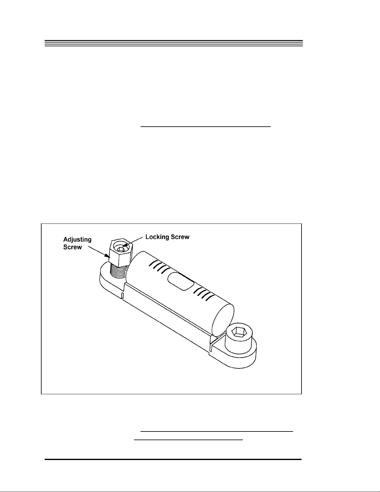
Adjustment and Maintenance 4
Once this procedure is finished, the tripod is adjusted so that the cart is
traveling vertically. Without changing anything the bubble levels should now
be reset to indicate level.
4.2.2.10.Setting the Bubble Levels on the Tripod
Once the cart travel is vertical, the tripod bubble levels should be adjusted to
show level. This step is necessary so the cart travel will be vertical when the
bubbles are level. Adjust the levels by loosening the M3 screw with a 2.5M
socket inside the outer brass screw and adjusting the brass screw, then
locking the assembly using the internal screw (see Figure 4-4). The thread on
the outer brass screw is delicate and can be damaged easily by turning the
brass part when the internal screw is tight (locked). This procedure will
ensure that the rods on which the cart travels are vertical when the bubbleslevels on the tripod are leveled. Having the cart travel vertically helps reduce
damage to the test mass during the catch phase of the drop.
Figure 4-4 Tripod bubble level
4.2.2.11.Adjusting Mirrors 3 & 4 to steer beam through
dropper and make beam vertical.
4-14
Page 73

Adjustment and Maintenance 4
This step assumes that the tripod levels have been set so that level ensures
that the cart travel is vertical. Now we will adjust the interferometer so that it
is referenced to the tripod tray bubble levels that were set in the last step. This
next adjustment will ensure that the beam is vertical and travels cleanly
through the dropper when the dropper and tripod are sitting on the
interferometer base with the bubble levels indicating level. Mirrors #3 and #4
will be used to translate the beam so that it enters and exits the dropper
without clipping on the tubes of the drag free chamber. Another requirement
is that the beam is also traveling vertically into and out of the dropping
chamber. Although both mirrors translate and tilt the beam, it is good to first
use mirror #3 as the translation mirror and #4 to adjust the verticality of the
beam during the alignment procedure. First, lower the tripod/dropper onto
the interferometer base. Level the interferometer base until the levels on the
tripod/dropper are centered. Put a dish of alcohol on the floor below the
interferometer base. Hold a white card over the dish of alcohol and adjust
mirror #3 (farthest from the first beamsplitter) until the beam is traveling
through the dropper system cleanly. Remove the card and look into the
telescope and you will see the reference beam and the return beam from the
alcohol dish. Adjust mirror #4 until they overlap in the telescope (this adjusts
the verticality of the beam). [DO NOT ADJUST THE LEGS OF THE
INTERFEROMETER BASE- WE WANT TO LEAVE THE INTERFEROMETE
BASE REFERENCED TO THE BUBBLE LEVELS] Since this procedure may
also cause the beam to translate, it is often necessary to iterate the procedure
of translation using mirror #3 and aligning with the beam with vertical using
mirror #4. This procedure converges rather slowly and takes about 10
iterations.
4.2.2.12.Adjusting the Superspring position and final
adjustment mirror
The Superspring position must be set so that the test-beam returns cleanly
after going into and out of the Superspring. In addition, it is important to get
the reference and test beams to overlap in the fringe viewer when the
translator plate underneath the interferometer base (twiddler) is in the midrange position. It may be necessary to adjust the position of the Superspring
interface plate (top mounting plate) that attaches to the bottom of the
interferometer and supports the Superspring chamber. The five M5 screws
4-15
Page 74

Adjustment and Maintenance 4
should be loosened slightly and the Superspring leveled. These M5 screws
have a M4 hex socket head. The Superspring should be unlocked
mechanically to let free the reference test mass. The translator plate
underneath the interferometer base (twiddler) should be put into its mid
range position so that the glass surface is normal to the beam. The top
mounting plate can be translated so that the beam travels cleanly through the
Superspring. Ideally, the test beam should overlap the reference beam in the
fringe viewer. Sometimes there is not enough range on the plate to get the
beams overlapped totally in the fringe viewer in the horizontal direction but
you should be able to get the two beams to have the same vertical position in
the fringe viewer. Finally, tighten the screws on the top mounting plate and
relevel the Superspring. Recheck the alignment after screws have been
tightened.
4.2.2.13.Final Mirror Translation-Getting Beams
Overlapped In Fringe Viewer
To move the test beam horizontally to overlap in the fringe viewer with the
reference beam it is sometimes necessary to translate the final adjustment
mirror underneath the interferometer base. Before doing so look through the
telescope and adjust the mirror until the two spots are coincident in the
telescope. This will ensure that the angle of the reference and test beams are
the same even though they may not yet be coaxial. Then you can turn all
three screws on the mirror mount in the same direction to translate the test
beam relative to the reference beam. Always watch the beam in the telescope
and make sure that you end up with the two beams overlapped in the
telescope. Once the reference and test beams overlap in the fringe viewer and
in the telescope they two beams are coincident and will produce good fringes.
4.2.2.14.Adjusting the APD signal detector
Preparations and Electrical hookups: Remove the dropper and tripod from
the interferometer base (IB) and remove the center section of the IB top cover
and the IB top cover containing the fringe viewer. Monitor the DC light level
from the avalanche photodiode (APD). It is usually best to do this using a
scope. The DC light level is available on the Analog Out port on the
interferometer base.
4-16
Page 75

Adjustment and Maintenance 4
Steering the beam onto the APD: The beam can be steered onto the APD
using the mirror mount holding the APD focusing lens. You should notice
that the beam is either on or off of the sensitive APD area (there is not a sharp
maximum, but a rather flat response) as you sweep the beam across the APD.
On most APD boards, the voltage is negative when light hits the APD. You
can verify this by blocking off the light using the REF BEAM beam-blocker.
Focusing the beam on the APD: Change the focus of the APD until the
maximum light level is reached. This focus adjustment is not very sensitive,
so sometimes it is useful to note the two positions of the lens where the light
level decreases by a fixed amount and then set the lens to the mid-position for
the maximum level. Tighten the locking nut for the focusing lens.
4.2.2.15.Adjusting The Fringe Amplitude
Put the dropper/tripod back on the interferometer base. Level the
interferometer base to the bubble levels on the dropper and raise the tripod
by one full turn of the tripod feet. Mount the Superspring. Align the test
beam and reference beam in the fringe viewer. Put the dropper into OSC
mode and maximize the fringes using the last mirror adjustment and
twiddler underneath the interferometer base. Do not forget to lock the laser.
Once the fringes are maximized, you should adjust the λ/2 plate (or optical
isolator) so the fringes are as large as possible without clipping on the edges.
When the light level is too high, the amplifier will saturate, producing a
flattened or clipped response instead of the usual sine-wave fringes that
should be produced. Once this light level has been adjusted, tighten the
screws holding the λ/2 plate (or optical isolator). Use a M2.5 hex socket
wrench for the λ/2 plate or a M3 wrench for the optical isolator.
4.2.2.16.Replace all covers and tighten all screws
4-17
Page 76

Adjustment and Maintenance 4
4.3. The Superspring
4.3.1.REPLACEMENTS AND
ADJUSTMENTS
4.3.1.1.Removing the Superspring Cover
If it is necessary to remove the top flange for any reason, be sure to replace
the flange in the same orientation. Align the large ear of the top flange
directly above the travel lock knob on the service ring.
FLANGE, DUE TO INTERNAL ELECTRICAL CONNECTIONSTHROUGH
THE SERVICE RING.
The top flange and Superspring cover may be removed as a unit by removing
the six screws holding the cover to the top of the service ring and lifting the
cover assembly straight up.
Most routine maintenance can be accomplished at this point, except for
replacing the coil (linear actuator), the mainspring itself, and its upper
hanger. To accomplish these tasks, the service ring and bottom flange must
be removed.
! DO NOT OPEN THE COVER BY REMOVING THE BOTTOM
4.3.1.2.Removing the Service Ring
Disconnect the wires between the bulkhead fitting and the circuit board,
emitter, detector, and motor by unplugging the in-line connector closest to
the bulkhead (electrical feedthrough connector), then remove the electrical
feedthrough from the service ring.
4-18
Page 77

Adjustment and Maintenance 4
CONNECTORS FOR LATER RECONNECTION.
Remove the travel lock knob by removing the flat-head screw from the center
of the knob and sliding the knob off the shaft. The knob is comprised of three
pieces: the brass knob, the control spring retainer, and the internal spring.
With the knob removed, the two screws holding the travel lock knob
assembly are exposed. Remove these and slide the assembly out of the
service ring (the travel lock to service ring interface is sealed with Teflon
sealer).
The service ring and bottom flange can be taken off together by removing the
three screws securing the base plate of the Superspring structure to the
bottom flange.
! MAKE SURE TO NOTE THE COLOR CODING ON THE
4.3.1.3.Replacing the Coil (Linear Actuator)
The permanent magnet assembly of the coil is attached to the base plate, and
the voice coil pusher is attached to the emitter/detector block of the support
structure.
Remove the service ring as described previously.
Remove the base plate by loosening the three 3mm barrel clamp screws that
secure the rods to the plate. Carefully lift rod assembly off bottom plate.
Remove two shoulder screws that hold travel lock fork on (from underneath)
and slide travel lock fork assembly off main rod. Unhook three support
springs from O-rings and remove lower triangular spring plate. This plate is
held on by four 3-mm screws. Be careful not to cut or score the O-rings. Note
orientation of emitter-detector block and remove block (six 3mm screws in
deep counter bore holes). Remove the permanent magnet assembly from the
base plate.
4-19
Page 78

Adjustment and Maintenance 4
Remove the voice coil by removing its three attachment screws inside the
emitter-detector block.
Reverse the procedure for reassembly.
4.3.1.4.The Mass Mainspring/Hanger
member which is soldered into the Superspring hanger and the coarse
adjustment screw. Mishandling of the mainspring may cause the wire to
break, allowing the hanger, spring, and test mass to drop.
! BE VERY CAREFUL NOT TO BEND THE FILAMENT WIRE IN
THIS ASSEMBLY.
It is highly recommended that this procedure be done at Micro-g Solutions.
Necessary tools and fixtures:
! The upper spring hanger assembly has a flexible thin wire
4.3.1.5.Replacing the Flexures
• A small table with leveling screws that can hold the Superspring (in
the field, one could use the entire tripod or just the leveling feet).
• A pulling tool (music wire 16” long with m 1.6 threads on one end) to
pull the main spring through the main tube.
• Metric hex wrenches.
• Metric open-end wrenches(m 5.5 and m 6).
• Plastic Gloves: It is best to handle the test mass with plastic gloves.
• Measurement tools (calipers and/or ruler).
4-20
Page 79

Adjustment and Maintenance 4
Remove the Superspring cover as previously described. Put a dust cover
over top of the main tube to keep dust from falling on the test mass and
upward-facing corner cube (a piece of paper or foil over the tube will suffice).
Remove the service ring as previously described.
Place a shim of hard foam or rubber between top rod ring and top triangular
plate approximately 6mm thick and use a cable tie to fasten the two plates
together. (Limiting the travel of the center tube assembly will help to avoid
damaging the delta-rod flexures during disassembly).
Loosen the three 3mm barrel clamp screws that hold the three rods to the
bottom plate. Disconnect wires from pre amp circuit board and carefully lift
rod assembly off bottom plate. Note : it is easier to do the next steps if the
assembly is blocked up 6’’- 8’’ so one can work underneath the assembly.
Remove two shoulder screws that hold travel lock fork on (from underneath)
and slide travel lock fork assembly off main rod. Unhook three support
springs from O-rings and remove lower triangular spring plate. This plate is
held on by four 3-mm screws. Be careful not to cut or score the O-rings. Note
orientation of emitter-detector block and remove block ( six 3mm screws in
deep counter bore holes).
Note: The test mass, spring, and flexure will come out with the emitterdetector block. Wear plastic gloves when handling copper test mass to
prevent finger prints and rubbing off black coating. Remove spring from
copper test mass. Note how far upper anchor is screwed into the main spring
(count how many spring turns are on the screw). Put the lower lock nut onto
the new flexure assembly. Remove broken flexure-anchor and carefully screw
new flexure-anchor into spring to the original position.
Thread the pulling tool through one nut, top lever and down center tube.
Carefully thread tool into top of flexure (coarse adjustment screw) of main
spring assembly. Pull tool up until spring hangs and then thread copper test
mass onto lower anchor of main spring assembly (tighten lower anchor). Pull
wire tool, lifting test mass ,and guide coarse adjustment screw through top
4-21
Page 80

Adjustment and Maintenance 4
lever. Screw on top nut to hold in position then remove the tool. (Set
approximately in center of coarse adjustment screw travel). Rotate test mass
so beam holes in top lever and copper test mass roughly match.
4.3.1.6.Assembling the Superspring
Replace emitter-detector block in the original orientation. The emitter (two
terminal device with red/white wires) should be oriented below lever pivots.
Replace lower triangular spring plate and attach support springs. Slide travel
lock fork assembly onto shaft and re-install the two shoulder screws. Replace
spring assembly into lower plate being careful of voice coil . Note: do this on
a flat surface so the rods seat flush with the bottom of the lower plate , then
tighten barrel clamps. Check movement of center tube by blocking up travel
lock fork assembly (so it doesn’t rub), removing wire tie and foam back, then
gently bouncing center tube and checking to see if it moves freely. NOTE:
Test mass must be centered in cage (hanging plumb), and wires must not
drag. Replace spring assembly into service ring. Insert 6mm screws but don’t
fully tighten. Replace the travel lock assembly. Rotate the main spring
assembly in the service ring so that the travel lock fork has equal clearance
around the two shoulder screws, then tighten 6mm screws.
Install electrical feedthrough. Re-connect all electrical connections. Level the
Superspring by viewing on each side of copper mass and centering in cage
(place entire Superspring on an adjustable table to change where the mass
hangs). Note that the mass should hang down approximately 1.5mm from
the point where it makes contact with the top of the cage assembly as the
system is travel -locked.
Use the Superspring controller to drive the zero-positioning motor (ZPM)
until the sphere voltage is zero. Measure the gap between the two levers near
the ZPM. Adjust the coarse adjustment screw so that when zeroing the
sphere voltage, the motor will end up in its center of travel position (about
6mm gap between lever arms ±0.5mm). Note that when you are far off of the
detector the sphere voltage starts at zero and then goes to a maximum and
then over a short range goes through zero (it looks like an S curve). Make
sure sphere detector voltage goes +/- to assure true zero position.
4-22
Page 81

Adjustment and Maintenance 4
Viewing from top, carefully rotate the corner cube and visually align the
beam holes in top lever with the ones in the copper Test mass, adjust by
rotating the coarse adjustment screw and lock in position by tightening both
top and bottom nuts.
Note 1: This will take time as the Test mass must settle down after each
adjustment.
Note 2: Be careful not to let dust or debris fall onto corner cube. Re-check the
level of the test mass and set level bubbles by turning brass screws. Lock
position with center lock screw. Replace the Superspring cover as previously
described.
4-23
Page 82

Adjustment and Maintenance 4
4.3.1.7.Replacing the Focus Lever Motor
Loosen and remove the nut on the focus adjustment screw. Lower the focus
lever motor assembly off the fulcrum lever.
Loosen the set screw holding the hex bushing to the motor shaft and raise the
bushing out of the way. The screws holding the motor to the motor mount
are now accessible, and can be removed. Reverse the procedure to install the
new motor.
4.3.1.8.Adjusting the Micro-Switches
Adjust the trip positions of the micro-switches that control the limits of travel
of the focus adjustment motor by changing the position of the set screws in
the actuator arms. The limit switches should shut off the zero-positioning
motor (ZPM) when the gap between the focus lever and the fulcrum plate is
4-8mm.
4.3.1.9.The Aneroid Wafer Assembly
To compensate for the thermal expansion and contraction of the Superspring,
an aneroid wafer assembly adjusts the position of the top hanger. The
position of the aneroid assembly is set by the manufacturer, and should not
need to be adjusted.
4.3.1.10.The Delta Rods
Five delta rods (arranged in an upper V-shaped array, and a lower triangular
array) provide a linear way system for the internal support structure of the
Superspring. If a delta rod needs replacement, contact Micro-g Solutions for
parts and procedures.
4-24
Page 83

Adjustment and Maintenance 4
CLEARANCE BETWEEN THE VOICE COIL (PUSHER) AND THE
MAGNET ASSEMBLY. IT IS IMPERATIVE THAT THE ASSEMBLY NOT
RUB OR DRAG!
To field check the alignment, measure the gap between the
support structure pins and the center tube assembly with a feeler gauge.
This gap should be equally spaced (approximately .003-.005”) all around. If
the support pins touch the center tube assembly, a bent delta rod is indicated.
! THE POSITION OF THE DELTA RODS DETERMINES THE
4.4. Timing System and Data Acquisition
4.4.1.TIMING
The timing system consists of the avalanche photo diode (APD) board, the
scaler-counter board, the rubidium oscillator and the universal time interval
counter (UTIC). Data are taken by two different interface cards inside an
IBM-compatible 386 (or better) personal computer. The computer processes
the data, compiles statistics, and computes a gravity value, including certain
corrections (e.g., for the tides and the gradient).
Optical fringes are produced in the interferometer by combining the portion
of the laser beam hitting the freely falling and reference retroreflectors (the
corner cubes) with the portion traveling directly through both beam splitters.
A fringe is produced every time the falling object traverses a distance equal to
the wavelength of the laser, lambda, over two (
falling object changes, the frequency (f) of the fringe signal is swept according
to f = 2gt/
by an APD mounted in the interferometer base.
The zero-crossings of the fringes provide very good fiducial marks which can
be used for timing. The zero-crossing points of the a.c.-coupled fringe signal
are determined using an ultrafast comparator. The comparator outputs a
square-wave version of the frequency-swept fringe signal. The comparator is
located on the APD circuit board.
4-25
λ, where g = gravity and t = time. The optical fringes are detected
λ/2). As the velocity of the
Page 84

Adjustment and Maintenance 4
The scaler-counter keeps track of how many fringes have gone by and
measures the absolute time of occurrence of these fringes. The scaler-counter
scales (divides) the fringes by a number which can be set on the scalercounter board (typically preset to 4000).
The 10-MHz signal from the rubidium oscillator is also divided by a preset
factor in the scaler-counter (usually 2000). The time interval between the
occurrence of each scaled fringe and the next scaled clock pulse from the
rubidium oscillator is measured with the UTIC. The computer records each
time interval, the number of clock signals, and the number of scaled fringes
since the last time interval measurement. This information is used to
construct the absolute time of occurrence of the scaled fringes.
The time of occurrence of each scaled fringe and the distance derived from
the number of fringes that have passed can be expressed as a time and
distance pair. The data are then fit to a parabola by the computer to
determine a best value for the acceleration—a gravity value.
4.4.1.1.Avalanche Photo Diode Printed Circuit Board
This circuit detects the optical fringes produced in the interferometer. The
FG5 uses a 50-MHz APD which is powered by a high-voltage module
mounted inside the interferometer base.
A high-speed comparator and 50-Ω driver on the APD board minimize noise
problems on the long cables between the interferometer base and the scalercounter board. The analog and digital versions of the fringe signal are both
available on BNC connectors mounted on the interferometer.
4.4.1.2.APD Board and Photo Diode Supply Module
The APD board is mounted inside the interferometer base, along with the
high voltage power supply module. The APD is mounted directly on the
board. The APD's high-voltage bias is zener-limited to 600 volts (on-board).
Two potentiometers are used to set the temperature coefficient and voltage
supplied to the APD.
4-26
Page 85

Adjustment and Maintenance 4
The analog output is buffered by an OP AMP directly from the APD. The
zero-crossing of the fringe signal is determined by the high speed
comparator, which in turn drives a 50-Ω line driver chip. A 40-mV hysteresis
is implemented on the discriminator to avoid multiple triggering. Positive
zero-crossings of the fringe signal are detected and begin the leading edge of
the TTL fringe signal. This TTL fringe signal leaves the board through an
SMA connector, and is available outside the interferometer on a BNC
connector labeled TTL. The TTL signal is used for timing by the gravimeter
electronics.
All on-board voltages are derived from the ± 15V supply with linear
regulators: ± 6 volts for the APD , and ± 5 volts for the discriminator and 50Ω
TTL driver.
APD SIGNALS
CONNECTOR TYPE DESCRIPTION
Digital (SMA) output
Analog (SMA) output buffered fringe output
HV 6 Pin Amp HV Module
Power 3 Pin Amp power from Lemo connector
*NOTE: The Power Technologies module is supplied from the +15V supply,
and is connected to J3, J5, and J6 of the APD board.
Table 4-1
TTL fringe signal (50-Ω)
4-27
Page 86

Adjustment and Maintenance 4
4.4.1.3.Scaler-Counter Printed Circuit Board
The scaler-counter board has several major functional blocks:
1. Clock discriminator
2. Clock scaling
3. Scaled clock count accumulator
4. Fringe scaling
5. Scaled fringe accumulator
6. Accumulator/computer data latching
7. Miscellaneous I/O interface circuitry
The incoming clock signal is converted to TTL levels (1), and then scaled (2)
according to a three-digit hexadecimal value selected with three PCB hex
switches. The scaled clock output of this circuit increments the 10-bit clock
accumulator (3) and is also sent to the UTIC via a BNC connector on the front
panel. Except that it does not need a TTL discriminator, the fringe scaling
circuit (4) is identical to that of the clock scaler. The scaled fringes are
counted by a 4-bit accumulator (5), and are passed on to the UTIC via a front
panel BNC connector.
The leading edge of the latch pulse from the UTIC latches (6) the current
values of the scaled clock and fringe accumulators into buffers, along with the
states of the "data_valid" and "up/down" status lines. The accumulators
themselves are then cleared by the trailing edge of the delayed latch. To
indicate data available for reading, an extended latch pulse is sent to the
computer.
A control line from the computer, /DIS, disables the fringe output to the
UTIC so that an incoming fringe cannot retrigger the UTIC until after the
computer has finished its current data read operation.
Several other signals are routed to and from the computer through the scalercounter board. They are specified in Table 4-2.
4-28
Page 87

Adjustment and Maintenance 4
4-29
Page 88

Adjustment and Maintenance 4
SCALER-COUNTER SIGNALS
BNC INPUTS DESCRIPTION
Clock In
Latch In TTL pulse from UTIC that latches count data for
Input Fringes
Valid Data TTL signal from controller indicating object in free-
Up/Down Status TTL signal from controller indicating object is in
Spring Status TTL signal from Superspring indicating proper
Laser Status TTL signal from the Laser indicating lock status
Stat 1 undedicated TTL-compatible status inputs to
50-Ω terminated input from 10-MHz Rubidium
Oscillator
reading by the computer
50-Ω terminated TTL prediscriminated fringe
signal from APD board
fall
the ascending/descending phase of throw
trajectory
operation (not implemented)
computer
BNC OUTPUTS DESCRIPTION
Spring Zero TTL signal telling the Superspring to re-zero itself
(not implemented)
Scaled Fringes TTL output to UTIC
Scaled Clock TTL output to UTIC
4-30
Page 89

Adjustment and Maintenance 4
Throw Init TTL control line to controller used to initiate a
throw cycle
Laser Control TTL signal to laser controller used to indicate
which mode to lock (red or blue)
Table 4-2 Scaler Counter Signals
DB-37 CONNECTOR SIGNALS TO COMPUTER
PIN NAME TYPE DESCRIPTION
3 FL3 output latched fringe count, bit 3
4 FL2 output latched fringe count, bit 2
5 FL1 output latched fringe count, bit 1
6 FL0 output latched fringe count, bit 0
7 VALIDL output latched "data valid" status bit
8 U/D_L output latched "up/down" status bit
9 DL9 output latched clock count, bit 9
10 DL8 output latched clock count, bit 8
17 GND power ground connection
19 GND power ground connection
21 GND power ground connection
22 CTL1 input laser control signal
23 CTL0 input spring zero signal
24 /DIS input fringe output inhibit
25 INIT input throw init signal; also clears clock and
fringe count accumulators
26 STAT2 output undedicated "status input 2" bit
27 laser stat output undedicated "status input 1" bit
28 SPRINSTAT output spring status bit
4-31
Page 90

Adjustment and Maintenance 4
29 LATCH output (extended) "latch" signal to computer
30 DL7 output latched clock count, bit 7
31 DL6 output latched clock count, bit 6
32 DL5 output latched clock count, bit 5
33 DL4 output latched clock count, bit 4
34 DL3 output latched clock count, bit 3
35 DL2 output latched clock count, bit 2
36 DL1 output latched clock count, bit 1
37 DL0 output latched clock count, bit 0
Table 4-3 DB37 Connector
4.4.1.4.Rubidium Oscillator
The FG5 uses a rubidium oscillator as a frequency standard (atomic clock).
The oscillator generates a 10-MHz sine wave with amplitude of .5Vrms into
50 Ω. It is used by the UTIC and scaler-counter to provide accurate time
information. The oscillator is split by a 50 Ω
clock is sent into the 10-MHz IN BNC on the back of the UTIC and also into
the Clock In BNC on the back of the scaler counter.
4.4.1.5.Universal Time Interval Counter
To measure the time between a scaled fringe and the next scaled clock, the
FG5 uses a Universal Time Interval Counter (UTIC). The scaler-counter
SCALED FRINGES signal is connected to the front A input of the UTIC,
while SCALED CLOCKS signal is connected to the B input. After each time
interval is measured, the UTIC generates a LATCH signal from a rear BNC.
The LATCH signal is connected to the Scaler/Counter where it is used to
latch the clock and fringe number onto the output pins of the parallel I/O
port of the Scaler/Counter. The UTIC is controlled and read by the computer
through an IEEE-488 cable.
POWER splitter. From there, the
4-32
Page 91

Adjustment and Maintenance 4
4-33
Page 92

Adjustment and Maintenance 4
UNIVERSAL TIME INTERVAL COUNTER SIGNALS
Front Panel:
Name Type Destination Name
B BNC Scaler/Counter SCALED CLOCK
A BNC Scaler/Counter SCALED FRINGES
Back Panel:
LATCH BNC Scaler/Counter LATCH IN
10-MHz IN BNC Rb oscillator
STD PORT IEEE computer
Table 4-4 UTIC Signals
The proper set-up of the UTIC is accomplished automatically in the software.
The OLIVIA program sets the A and B inputs to be 50-Ω terminated, the clock
reference to be external, and the clock frequency to be 10 MHz. The UTIC is
set to measure positive mean time intervals only. The trigger levels for A and
B are set at 1.8 V.
4.4.2.DATA ACQUISITION
4.4.2.1.Computer Interface Cards
The computer running the system is a 386 DX machine (or better). To
interface the computer to the scaler-counter the FG5 uses a Metrabyte PIO-12
(SET TO 380 HEX). This card provides 24 bits of I/O. It is configured for 20
input lines and 4 output lines. The PIO-12 card has a 37-Pin D connector that
runs to the back of the SCALER COUNTER. The UTIC interface is a
Metrabyte DV-488 card (an IEEE-488). The IEEE-488 cable runs from the back
of the scaler-counter to the back of the UTIC.
4-34
Page 93

Adjustment and Maintenance 4
4.5. DROPPER CONTROLLER
The dropper controller is a flexible control circuit (programmable servo
controller) that can direct the motor to servo the cart (and test mass) to a
specified height in the dropping chamber using a rotary shaft encoder, or to a
specific velocity, again using the shaft encoder. The controller can also direct
the motor to track the test mass during free-fall using the sphere detector
system.
The dropper controller board uses an EPROM to allow control over the motor
drive signal sources (the shaft encoder and the sphere detector), as well as
programmable offsets (command voltages) for each servo mode. This
EPROM also controls the state-machine clock source, clearing the statemachine counter, and clearing the shaft encoder.
A second EPROM holds a programmable comparator level used for the
setting of trigger and hold points within the dropping chamber. One bit of
the second EPROM is also used to control the time-out circuitry (a safe-guard
that protects the motor and the test apparatus).
Eight bits address the two EPROM’s, giving a total of 256 programmable
states. One bit is reserved for a fail/standby state, reducing the system to 128
non-standby states. These remaining states are subdivided into modes
defined using three bits of latched data (a total possibility of eight modes).
Each mode can have an associated four-bit state-machine cycle (sixteen
possible states). A counter which can be clocked by an external signal (the
computer), by a window comparator level, or by a programmable reference
level in the dropping chamber controls the latter four bits. These clock
choices are stored in the first EPROM.
This architecture allows flexibility to program many different modes of
operation. Each mode can be associated with a programmable cyclic statemachine. The circuitry also allows programmable digital set points for
4-35
Page 94

Adjustment and Maintenance 4
critical positions such as launch points or hold points. The set points are
well-controlled against environmental variables.
The controller circuit board currently supports four different modes of
operation: STANDBY, MANUAL, OSCILLATE and DROP.
4.5.1.DROPPER CONTROL MODES
4.5.1.1.STANDBY
4.5.1.1.1.To Select
This mode is chosen upon power-up, when the front panel RESET button is
pressed, or when a time-out has occurred (usually indicating failure).
4.5.1.1.2.Function
The controller is in standby. The motor is turned off.
4.5.1.1.3.To Deselect
Press the front panel INIT button.
(Note: The initialize function can also be executed remotely through the INIT
BNC connector.)
! WARNING: IT IS DANGEROUS TO ALLOW THE COMPUTER
REPEATED INITIALIZE CAPABILITY. THE SYSTEM CAN ENTER THIS
STATE THROUGH TIME-OUT, WHICH MAY INDICATE SYSTEM
FAILURE.
4.5.1.2.MANUAL
4.5.1.2.1.To Select:
THIS MODE SHOULD NOT NORMALLY BE NEEDED BY THE USER AND
SHOULD NOT BE USED WITHOUT FULL UNDERSTANDING OF THE
CONTROLLER!
This mode is selected by turning the front panel selector switch to MANUAL
and pressing the INIT button.
4-36
Page 95

Adjustment and Maintenance 4
4.5.1.2.2.Function:
The front panel potentiometer controls a servo position for the cart. The cart
servo will not initiate until the trimpot is within a predefined window of the
actual cart position. This will time out after 20-30 seconds if the time out is
enabled (default).
IF THE TIME OUT IS DISABLED, BE CAREFUL TO NOT BURN OUT THE
MOTOR BY DRIVING IT INTO THE STOPS AT THE TOP OR BOTTOM.
4.5.1.3.DROP
4.5.1.3.1.To Select:
Set the selector to AUTO. Press the INIT button to initiate the drop mode.
4.5.1.3.2.Function:
The DROP mode has six states:
1. Standby: The motor is off and the system waits for a trigger signal
from the computer or from the internal timer (selected on front panel).
2. Lift: The cart servos to a constant lift velocity until the cart comes
within the window of the hold position.
3. Hold: The cart servos to a constant hold position.
4. Track: The cart servos to track the test mass with a separation of about
3 mm. This is adjustable.
5. Soft-catch: The cart tracks the test mass with a very slight separation.
6. Catch: The cart servos to a decreasing ramp velocity servo until about
5 mm. At this point the state-machine returns to the standby mode (1).
4.5.1.4. OSCILLATE
4.5.1.4.1. To Select:
Press INIT while the selector switch is set to OSC.
4.5.1.4.2. Function:
This mode causes the cart to move up and down smoothly (with a
constant velocity) in the dropping chamber. It is very useful for generating
fringes. DO NOT LEAVE IN OSC MODE UNATTENDED! Cumulative belt
4-37
Page 96

Adjustment and Maintenance 4
slip can cause the cart to drive into the bottom or top of the dropping
chamber and burn out the motor.
4.5.2.Analog Servo
The analog servo has three different sections. They are: Cart-position, Cartvelocity, and Sphere-position. The cart servos use the rotary shaft encoder as
a position/velocity sensor. The sphere servo uses the optical sensor mounted
on the cart.
4.5.2.1.Cart-Position
The cart position is given by an optical shaft encoder that is mounted on the
motor shaft. The base resolution is 500 counts per revolution. The outputs
are two quadrature signals which give information about the amount and
direction of shaft rotation.
The shaft encoder quadrature outputs are preconditioned by a custom
programmed gate array logic (GAL) chip called the AXQD2X. The outputs of
the AXQD2X are glitch-free clock pulses and an up/down bit. The resolution
of the shaft encoder is multiplied by two, giving 1000 counts per revolution.
The AXQD2X also has logic that helps clear the counters and keeps them
from an overflow or underflow condition.
The sixteen-bit counters feed a twelve-bit digital to analog chip (DAC) for use
in the analog servo. The top seven bits are also fed to a comparator that is
used for level settings that trigger different phases of the servo. The output of
the DAC is available on the front panel BNC called CART position.
The DAC output has a programmable offset corresponding to either (1) the
manual position controlled by the front panel knob, or (2) the hold position
trimpot on the controller board. The servo adds in some derivative or
damping that is set by the CART DAMP trimpot on the PC-board. The
overall gain is set by the HOLD GAIN trimpot on the PC-board.
4-38
Page 97

Adjustment and Maintenance 4
4.5.2.2.Cart Velocity
The servo takes the cart position derivative. A velocity lead trimpot on the
PC-board adds phase margin which tends to speed up or damp the servo in
the velocity mode. Servos that measure position and control velocity tend to
have a slow exponential response without this precaution.
A programmable reference voltage is added to the velocity signal. The servo
makes the actual cart velocity track these reference voltages. The four
references are called: throw, lift, soft throw, and catch.
The throw and lift are constant offsets set by trim pots on the circuit board.
The soft throw and catch are both linear voltage ramps whose slopes are
controlled with trim pots labeled SOFT THROW RAMP and CATCH RAMP.
Each reference voltage also allows an offset to be added using the trim pots
labeled THROW OFFSET and CATCH OFFSET. These ramps are used to
accelerate the cart during the throw phase and decelerate the cart during the
catch phase.
The gain for the velocity servo is set by the VELOCITY GAIN trimpot on the
PC-board.
4.5.2.3.Sphere Servo
The sensor for this servo is an LED focused spot-sensor. The operational
principle is a simple optical lever arrangement. An LED and linear detector
are mounted on opposite sides of the cart. A spherical lens mounted on the
test mass focuses the LED onto the linear detector, giving relative position
between the cart and test mass. The signal is preconditioned by a
preamplifier mounted on the cart. The position can be monitored on a front
panel BNC labeled SPHERE.
The servo consists of an active feedback servo and a passive feedforward
servo. The feedforward provides the approximate correct motor voltage
during the drop.. This reduces the demands on the feedback servo.
4-39
Page 98

Adjustment and Maintenance 4
4.5.2.4.Active Sphere Servo
The sphere signal is added with an offset called height and another offset
called hover height. The height offset is always added to provide a tracking
difference between the cart and the test mass during free-fall. The hover
height is switched in by the EPROM and gives an overall reduced offset
which makes the cart track the test mass very close to the rest position. This
is useful for catching the object near the bottom of the drop.
The sphere signal (sphere and offsets) servo uses a proportional and a first
derivative term. The proportional term is controlled with a trimpot called
SPHERE GAIN. The derivative term is controlled with the trimpot called
SPHERE DAMPING.
4.5.2.5.Feedforward Sphere Servo
This servo is made with a ramp waveform. The slope of the ramp is given by
the trimpot called RAMP SLOPE. The zero point, which should be at the top
of the drop or throw, is set by the ramp offset
4.5.3.Superspring Controller
The Superspring electronics comprise a system for locating the Superspring
mass relative to the support housing, a motor-driven mechanical lever system
for raising and lowering the mainspring, and an electromagnetic coil that
enhances the natural frequency of the mainspring by 2000 to 3000 percent.
Inside the Superspring are an SE-3455 infrared LED, a photo detector, and a
sphere signal preamplifier. An infrared beam from the LED shines through
an optical glass sphere attached to the bottom of the Superspring mass, which
is suspended from the end of mainspring. The sphere focuses the beam on
the photo detector. The detector outputs a signal to the preamplifier that
indicates the position of the Superspring mass in relation to the mainspring
support system.
4-40
Page 99

Adjustment and Maintenance 4
4.5.3.1.SUPERSPRING CONNECTIONS
Name TYPE Destination Name
Front Panel:
SPHERE OUT BNC BNC16 2H
COIL OUT BNC NC
Back Panel:
COMP OUT BNC NC
NOISE INJECT BNC NC
Table 4-5 Superspring Connections
The preamplifier relays the signal to the Superspring controller, which
controls a motor. The motor drives a lever system that raises and lowers the
mass and mainspring. Two micro-switches and diodes keep the motor from
raising or lowering the mass beyond a specified range.
A linear actuator coil and magnet system pushes and pulls the mainspring
support structure to track the Superspring mass.
The Superspring controller has six main parts:
1. LED driver
2. Sphere signal buffer
3. Window comparator
4. Motor driver
5. Active filter
6. Coil driver
4-41
Page 100

Adjustment and Maintenance 4
The LED driver supplies a constant current to drive the LED in the
Superspring can. This current can be adjusted internally using the
potentiometer (pot).
The sphere signal buffer buffers the signal from the Superspring can so it can
be routed to different parts of the board. The Sphere Detector Out BNC can
be low pass filtered at 1.26 Hz (FILTER ON).
The window comparator checks the LP-filtered sphere signal to see if it is
within the preset range. If the signal is within the window the Range Status
will be "High;" if the signal is out of the window the Range Status will be
"Low."
4.5.3.2.MOTOR DRIVE SELECTION
The motor driver circuit can be selected by an external switch with five
positions: OFF, WINDOW, AUTO, REMOTE, and MANUAL. This controls a
DC motor which can position the top of the main spring relative to the main
bracket. The position may need to be adjusted as the main spring slowly
stretches over time, or due to temperature or gravity changes. The DC motor
can lift (lower) the test mass so that the sphere position becomes more
positive (negative). This motor should only be used to position the mass but
should not be activated during the Superspring operation as a long period
isolation device.
4.5.3.2.1.OFF
This setting disables the DC motor that positions the top of the main spring.
The Superspring should be left in this mode when the active servo is
activated.
4.5.3.2.2.AUTO
The Superspring controller will try drive the DC motor using a feedback loop
so that the sphere signal is zero.
4.5.3.2.3.WINDOW
The Superspring controller will activate the motor when the sphere voltage is
out of range (larger than the window setting). The motor drives the sphere
voltage to zero and then is turned off. In principal the Superspring can be left
in this mode but it could re-zero during a measurement causing excess noise.
4-42
 Loading...