

Page 1

MicroFab Technologies, Inc.
www.microfab.com
MJ-AB User’s
Manual
Page 2

MJ-AB User’s Manual
MicroFab Technologies
1104 Summit Avenue, Suite #110
Plano, Texas 75074
Phone 972.578.8076 • Fax 972.423.2438
Page 3

Notice:
The information contained in this document is subject to change without notice.
MicroFab makes no warranty of any kind with regard to this material, including but not limited to, the implied
warranties of merchantability and fitness for a particular purpose. MicroFab shall not be liable for errors
contained herein or for incidental or consequential damages in connection with the furnishing, performance, or
use of this material.
Page 4

Warranty
The MJ-AB jetting device is warranted against defects in material and workmanship for a period of thirty days
from date of shipment. During the warranty period, MicroFab will, at its option, either repair or replace devices
that prove to be defective.
Limitation of Warranty
The foregoing warranty shall not apply to defects resulting from improper or inadequate maintenance by Buyer,
Buyer-supplied software or interfacing, unauthorized modification or misuse, or operation outside of the
environmental specifications for the product. MicroFab makes no claim that the jetting device will perform
with all fluids introduced to the device, or that the device will work at all frequencies and operating parameters
selected by the Buyer.
Page 5
MicroFab Technologies
1104 Summit Avenue, Suite #110
Plano, Texas 75074
Phone 972.578.8076 • Fax 972.423.2438
Equipment Series: MJ-AB Jetting Device
Mfg Date: Indicated by device Serial No.
General Safety Considerations
Warning The jetting device itself presents no general chemical hazard. However, safety measures
should be followed as outlined in the MSDS for fluids to be dispensed.
Warning If this product is not used as specified, the protection provided by the equipment could
be impaired. This product must be used in a normal condition only (in which all means
for protection are intact).
Page 6

Table of Contents
SECTION 1 - GENERAL INFORMATION 1
Introduction ...............................................................................1
Technical Specification.............................................................1
Facility Requirements................................................................2
Pneumatics ..................................................................................... 2
Electrical......................................................................................... 3
SECTION 2 - EQUIPMENT RATINGS 5
Supply Voltage...........................................................................5
Range of environmental conditions...........................................5
EQUIPMENT INSTALLATION 5
Unpacking and Inspection.........................................................5
Assembly....................................................................................6
Instructions for Protective Earthing..........................................6
Ventilation .................................................................................6
EQUIPMENT OPERATION 7
Hardware Overview ...................................................................7
Principles of Operation ..............................................................8
Initializing Jetting Hardware.....................................................8
Setup steps: .................................................................................. 10
Notes: ............................................................................................ 11
SUPPLEMENTAL PARTS 12
FACTORY SUPPORT 13
Page 7

MJ-AB USER’S MANUAL
Section 1 - General Information
Introduction
MicroFab’s MJ-AB jetting device has been developed to dispense single drops of
solvents, water-based fluids, and inks. With proper fluid preparation and device
maintenance, the jetting device will provide reliable delivery of fluid micro-drops.
Figure 1 - MJ-AB-01 Jetting Device
Technical Specification
The MJ-AB jetting device design has successfully jetted a wide variety of fluids.
Performance of the jetting device is closely tied to the characteristics of the fluid in use.
Typical fluids successfully jetted in this device have viscosities less than 40 centipoise
and surface tensions in the range of 0.02-0.07 N/m. Fluids with properties outside
these limits can be jetted if changes to the properties can be achieved with solvents or
changes in temperature.
The jetting device can be provided with orifice sizes ranging from 30-60 microns.
Depending on the operating parameters and the fluid, these devices can produce drops
ranging from 50-200 picoliters in volume.
Operating Range
Operating temperature between 20 and 150°C.
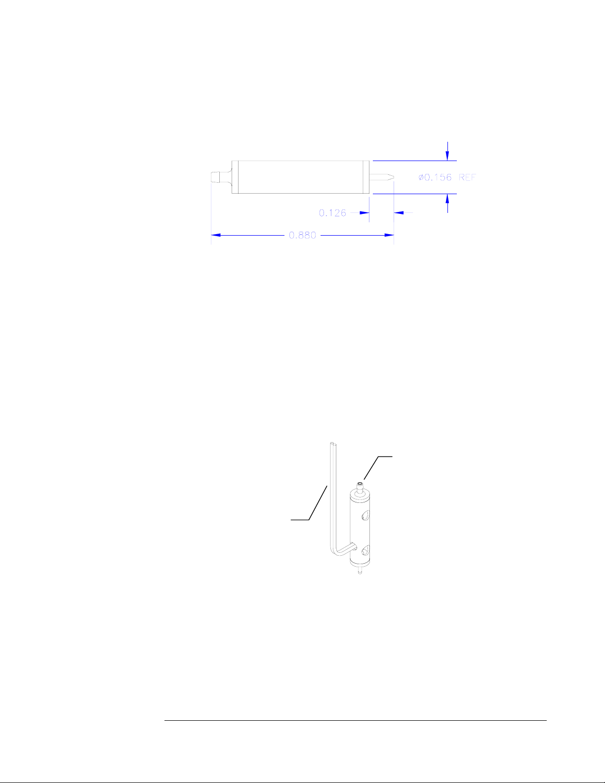
Physical Dimensions
Physical dimensions are shown in Figure 2.
1
Page 8
MJ-AB USER’S MANUAL
l
Figure 2 - Device Dimensions
Power Requirements
Required power - 115VAC/2A max; 50/60 Hz (for JetDrive electronics;
JetDrive can also be configured for 240V installation).
Facility Requirements
The jetting device, by itself, requires no connection to lab or machine power.
However, the support equipment for the jet does require some typical lab support.
Fluid Inlet
Electrical signa
Figure 3 - Fluid & Electrical
Pneumatics
Depending on the viscosity and contact angle of the fluid, the jetting device can require
either positive or negative pressure at the fluid inlet. There are two typical ways to
provide this backpressure. First, the backpressure can be provided by either a positive
2
Page 9
MJ-AB USER’S MANUAL
n
or negative pressure head provided by positioning the fluid reservoir. If the reservoir is
mounted a few inches above the jetting device, a constant positive pressure will be
provided. If it is mounted a few inches below, the orifice will realize a negative
pressure.
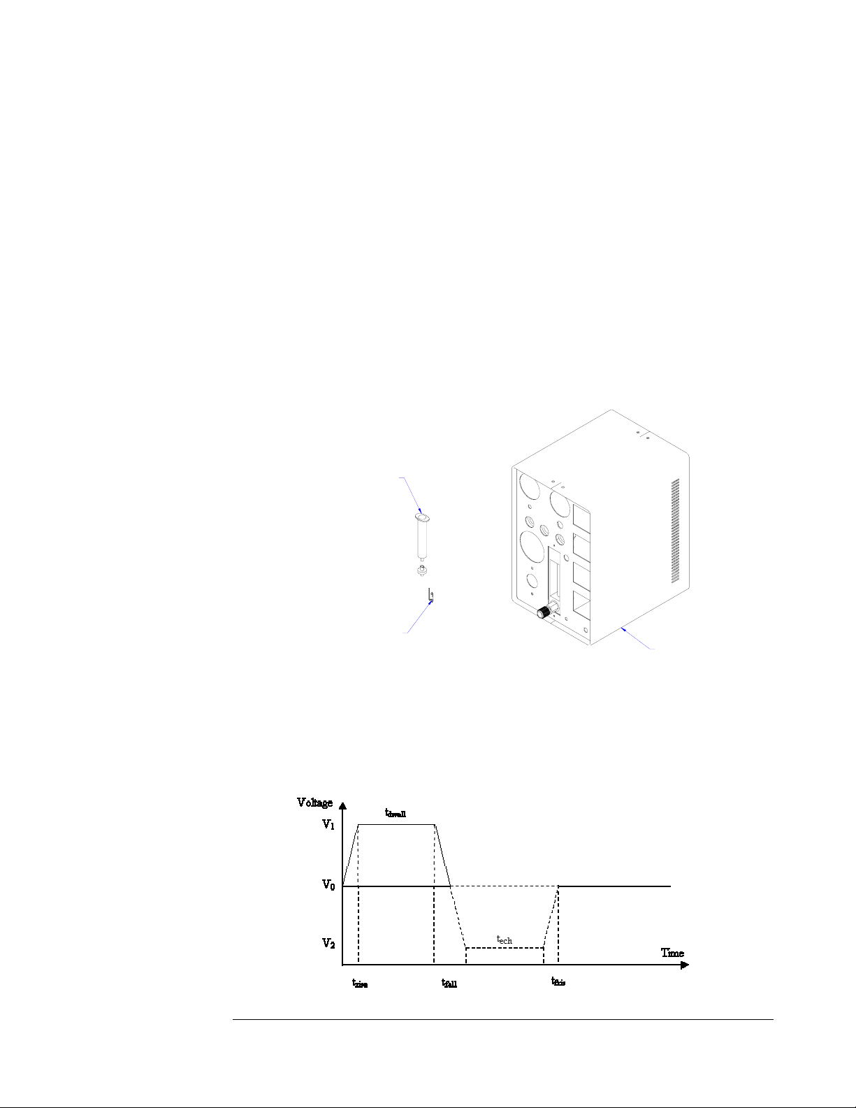
The second approach is to regulate existing compressed air or vacuum sources. By
inserting a pressure or vacuum regulator between the source and the jetting device, the
pressure can be adjusted. MicroFab provides such capability in it’s CT-PT-01
pneumatics panel. In this case, the lab facilities must provide a +15 PSIG source,
either through an air compressor or through a compressed gas tank. For negative
pressure, the regulator should be connected to a vacuum source of –24 in. Hg.
The two installations are shown side by side in Figure 4.
Reservoir
Jetting Device
Pneumatics Panel
Figure 4 - Back Pressure Control
Electrical
In order to generate drops, a pulse is sent to the PZT surrounding the glass capillary.
The shape of this waveform is shown in Figure 5. The minimum to maximum range
Figure 5 - Waveform Definitio
3
Page 10
MJ-AB USER’S MANUAL
for the jetting device is listed in Table 1.
Table 1 - Voltage Pulse Parameters
Voltage level 1 0 to 100 V
Voltage level 2 -100 to 0 V
t
rise
t
dwell
t
fall
t
ech
t
fris
Frequency 1 Hz to 20 kHz
1 – 300 µs
3 – 800 µs
1 – 300 µs
3 – 800 µs
1 – 300 µs
MicroFab offers a controller (part no. CT-M3-01) that has been designed to meet or
exceed these parameters. However the same function can be accomplished by
properly implementing a waveform generator and a voltage amplifier from qualified
manufacturers. It is important in either arrangement, however, to make sure that the
output connector from the voltage source mates with the connector provided on the
jetting device.
4
Page 11
Section 2 - Equipment Ratings
Supply Voltage
Consult the manufacturer’s data sheet for supply voltage requirements of the pulse generator used
for operation.
Range of environmental conditions
The MJ-AB device has been successfully operated in the temperature range of 20° to 150° C. It is
intended for use in a normal laboratory environment.
Equipment Installation
Unpacking and Inspection
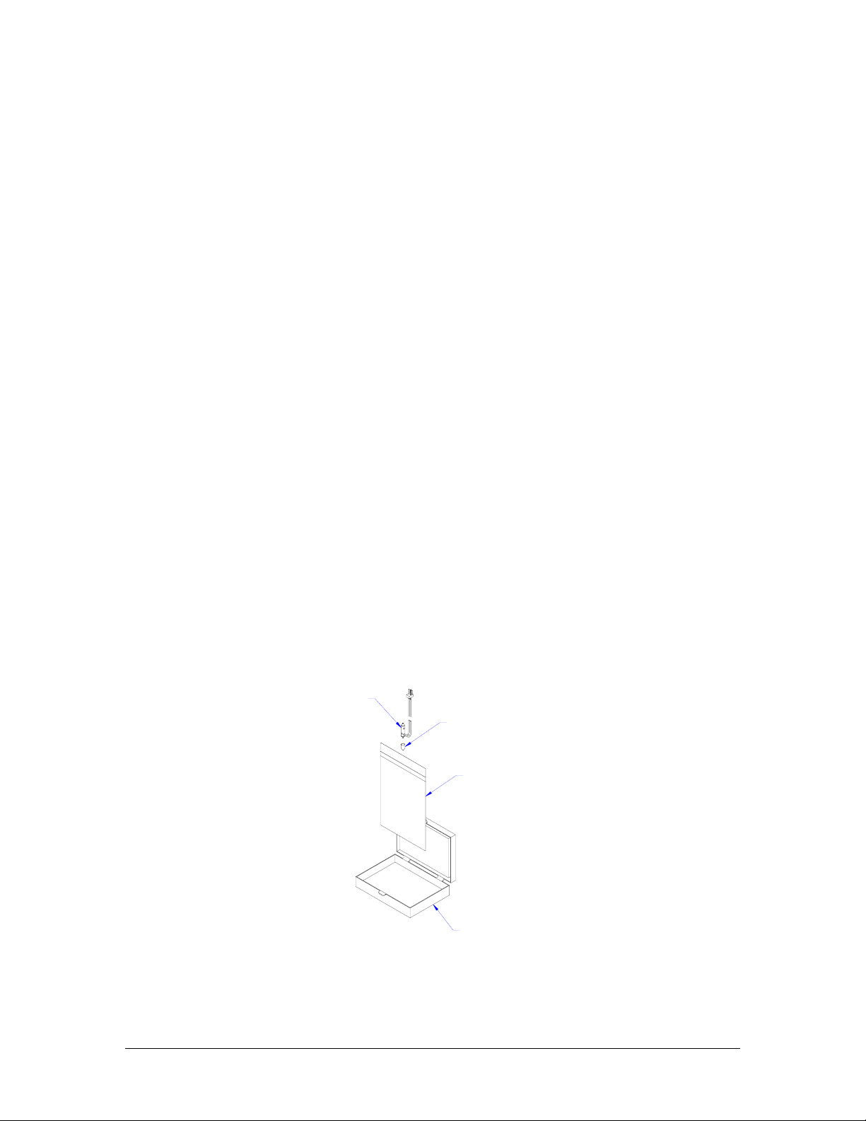
When received, the MJ-AB device will be individually packaged in a plastic box and a bag. The
glass tip of the jetting device will be covered by a protective shell. After verifying that the box is
labeled with the desired orifice diameter, the device can be removed from its bag and inspected.
Jetting Device
Tip cover
Plastic bag
Box
Figure 6 - MJ-AB Packing
5
Page 12

While removing the protective cap, be sure to pull straight away from the device. The glass tip
can be broken or damaged if the cap is pulled to the side during removal.
Assembly
The jetting device should be physically mounted by light clamping around the 0.156” case. No
attempt should be made to hold the jetting device by the glass tip.
Provisions must be made for routing tubing to the fluid fitting of the device. The outside
diameter of the barbed fitting is 0.051” at the largest portion of the barb. Flexible tubing which is
nominally 1/32” I.D. will fit securely over the barb.
In many cases it is advisable to use a filter compatible with the fluid to be jetted. Orifice sizes for
a MicroFab jetting device typically range from 30 to 60 µm. Filter sizes of 7 µm and smaller will
reduce the risk of contaminants clogging the orifices. It is important that the selected filter is
compatible with the fluid to be jetted and that adequate flow through the filter can be maintained.
Instructions for Protective Grounding
Protective grounding for the JetDrive III controller is provided through the ground terminal of
the plug providing power. Source power to the controller, or to a wave form generator selected
as an alternate, must provide protective grounding to this terminal in order to minimize the
hazard of a possible shock.
Ventilation
The MJ-AB jetting device itself requires no special ventilation for operation. However it is
possible that the fluid being dispensed will require a unique environment for reliable operation.
As an example, fluids that quickly dry in contact with air may need an elevated humidity to slow
this process. Additionally, the dispensed fluid may emit volatile fumes that must be captured and
disposed of. Both of these situations are the responsibility of the user of the device and beyond
MicroFab’s control.
6
Page 13
Equipment Operation
Hardware Overview
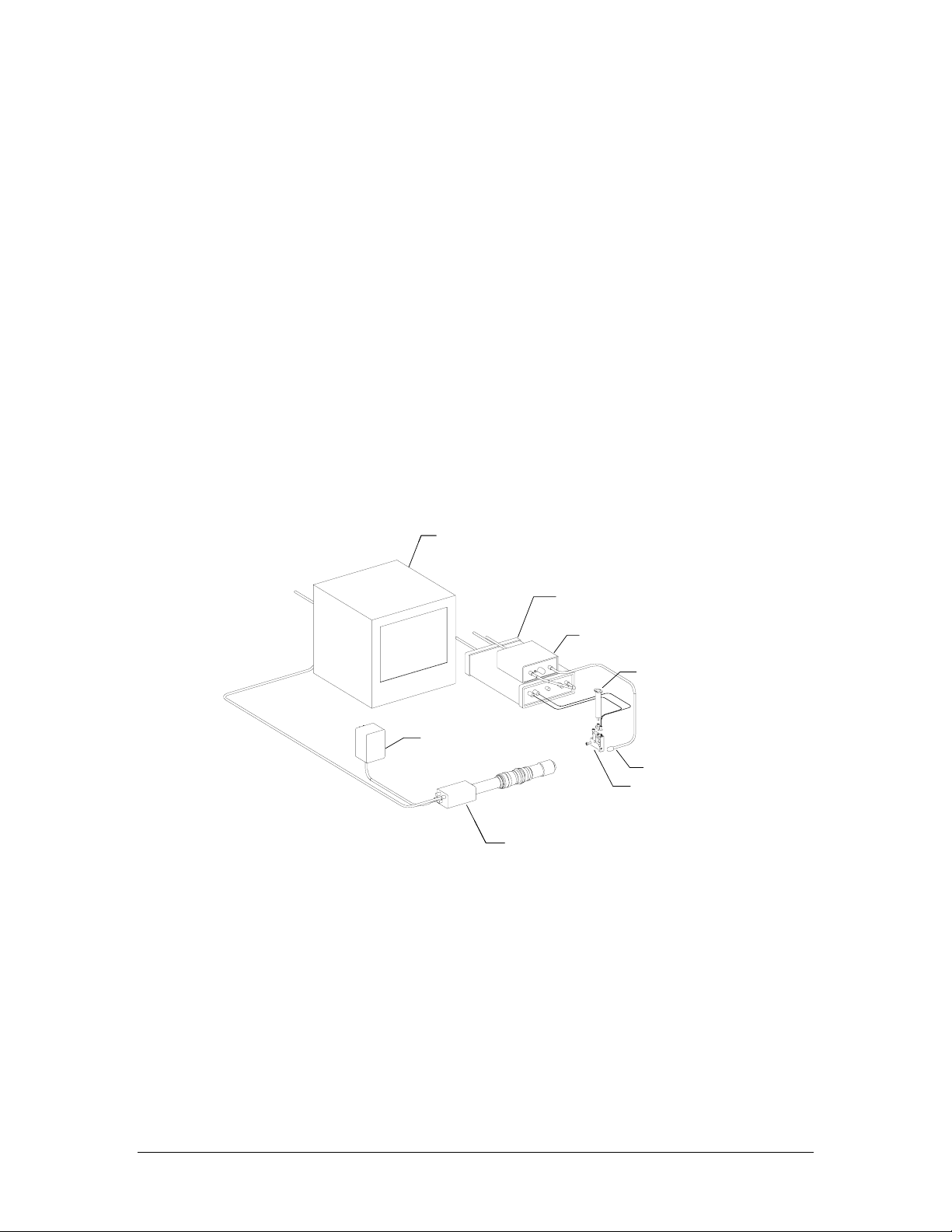
Figure 7 shows a typical set-up for a jetting test station. The key components are:
1. Jetting device (in this case, shown in a PH-03 print head for ease of mounting)
2. Fluid reservoir (shown with static pressure control)
3. Drive electronics with strobe interface
4. Drop observation camera and monitor
Video Monitor
Video Monitor
To 110 VAC
To 110 VAC
Drive
Drive
Electronics Box
Electronics Box
Strobe Interface
Strobe Interface
Box (see text)
Box (see text)
Reservoir
Reservoir
To 110 VA C
To 110 VA C
Camera Power
Camera Power
Supply
Supply
Figure 7 - Typical Set-up
Video Camera and Lens
Video Camera and Lens
Strobe LED
Strobe LED
Print
Print
Head
Head
Not shown in the figure is a personal computer. A PC is required in order to serve as the user
interface to download operating parameters to the drive electronics box. The software required
to perform this interface is included with the drive electronics (JetDrive III). For systems where
the voltage pulse is supplied by other equipment, variations on the figure will occur, although the
same components are required.
7
Page 14

Principles of Operation
The MJ-AB device consists of an annular piezoelectric actuator bonded to a glass capillary that is
connected at one end to the fluid supply and at the other end has an orifice generally in the range
of 30-60um. By applying a voltage to the PZT actuator, the cross-section of the tube capillary is
reduced/increased producing pressure variations of the fluid enclosed in the tube. These pressure
variations propagate in the glass tube towards the orifice. The sudden change in cross-section
(acoustic impedance) at the orifice, causes a drop to be formed. This mode of producing drops is
called drop on demand (DOD).
The same device can be used for continuous drop generation when the fluid is pressurized and a
sinusoidal signal is applied to the actuator. A Rayleigh type instability results in the break-off of
the fluid column into droplets. The continuous jetting results in a higher throughput.
A wide range of fluids can be dispensed with the requirement that the viscosity has to be lower
than 40 centipoise. Drop volume is a function of the fluid, orifice diameter, and actuator driving
parameters (voltage and timings) usually ranging from 50 picoliters to 200 picoliters. The
operating frequency is limited by the total driving time of the actuator and on the dispensed fluid.
Initializing Jetting Hardware
Hardware
The jetting device is the key element of the dispensing system. Each device is polished and
extensively cleaned prior to shipment. Maintaining this cleanliness is extremely important to the
successful operation of the device. In many systems provided by MicroFab, a filter is supplied
prior to the inlet fitting of the jet. The fluid line or fittings between the filter and the device, and
between the filter and the reservoir, should be flushed and cleaned to assure that no particulates
are accumulated in the plumbing. In addition, compatibility of the fluid under test and each
plumbing element should be understood by the user. If the fluid to be dispensed chemically
attacks any of the plumbing components, the resulting contamination may result in a “clog” at the
orifice.
Final testing of the jetting device prior to shipment is done using Isopropyl Alcohol. During
initial testing of the MJ-AB device, this fluid is recommended to help demonstrate that all parts of
the system are operating normally. After new operators are comfortable with dispensing IPA, the
actual fluid to be tested can be loaded into the reservoir.
Observation system
To observe the drop formation, a CCD camera can be used to observe the jet tip. MicroFab
offers a suitable system (model no. CM-VS-01). An appropriate microscope can also replace the
camera.
The total magnification to the display should be in the range of 50 to 100 times. An LED
synchronized with the PZT pulse provides lighting. The delay between the PZT pulse and LED
pulse is adjustable, allowing the capture of the drop formation at different stages of development.
8
Page 15
Drive electronics
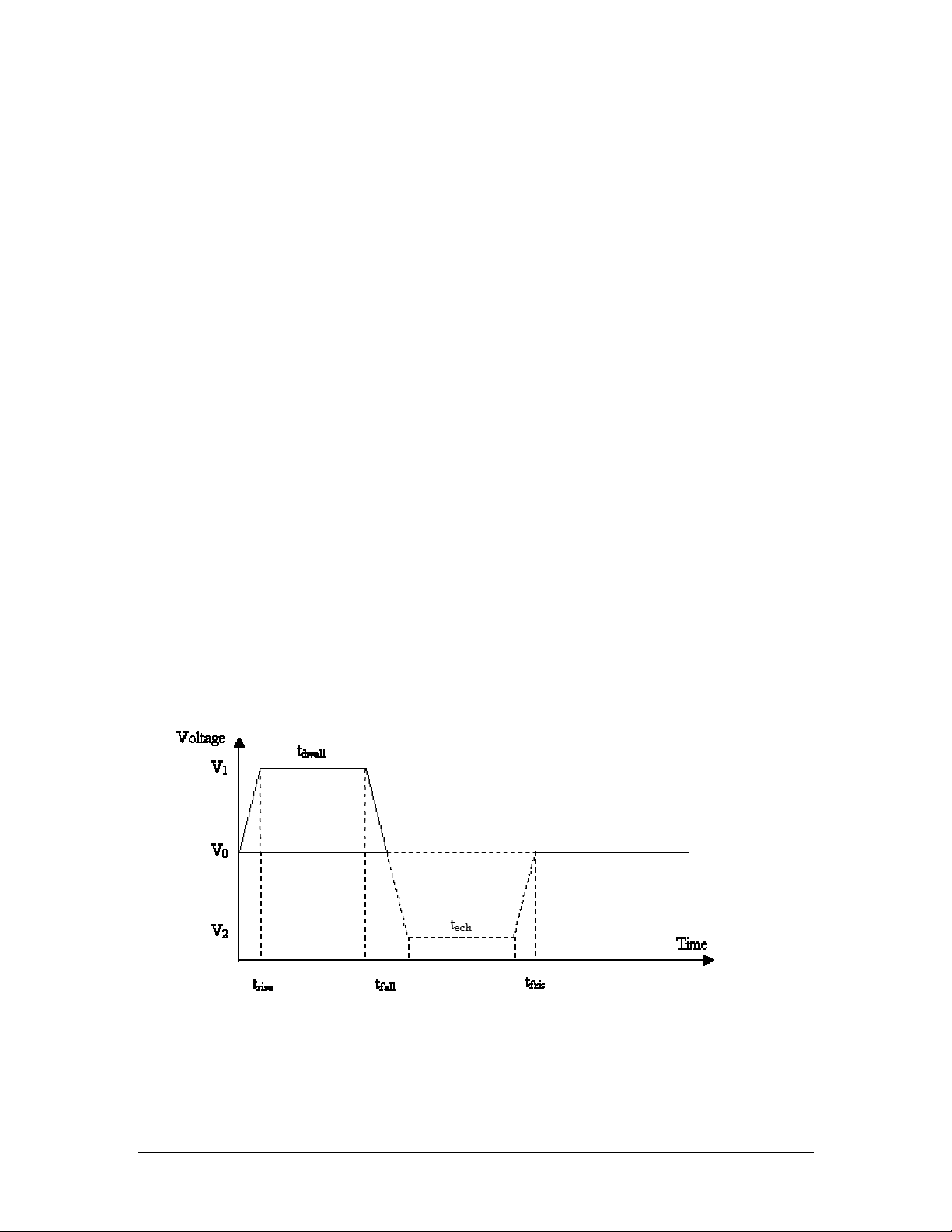
To use the device as a drop on demand dispenser the waveform presented in Figure 8 has to be
supplied to the red wire of the piezoelectric actuator with the black/blue wire connected to the
ground of the drive electronics unit. The driving signal can be unipolar or bipolar, depending on
the fluid used. The parameters are t
= initial rise time; t
rise
transition time from high voltage to low voltage; t
= time at low voltage (V2); t
echo
= time at high voltage (V1); t
dwell
frise
=
fall
= final rise
time. The voltage V0 is normally set to zero and V1= -V2 . The piezoelectric actuator has a
capacitance of about 1 nanoFarad.
The length of device and the jetted fluid dictates the timings. To minimize the driving voltage the
rise and fall times should be short (2-3ms). An optimum value for the dwell time is approximated
as:
t
=2 L/c (1)
dwell
where L is the distance between the middle of the piezoelectric element to the device end and c is
the speed of sound in the dispensed fluid. For the MJ-AB device, the value of L is approximately
0.434” (11 mm). Typical dwell time values are between 15 to 35 ms. The echo time t
(if using a
echo
bipolar waveform) should be adjusted for a clean break-off of the drop (generally about twice the
dwell time).
To achieve larger drop volumes with the same device (drop volume is also a function of the
orifice diameter) longer rise and dwell time values can be used (which also results in an increase in
the voltages V1 and V2).
The LED signal should be synchronized with the driving signal and have an adjustable delay from
the beginning of the pulse. By adjusting the delay the drop formation will be “frozen” at that time
from the beginning of the PZT pulse.
Figure 8 - Waveform Set-up
9
Page 16

Setup and operation
Important:
The glass tip of device is very fragile! Care should be taken to remove the
protective cap along the device axis otherwise the glass capillary outside the device will
break. A gentle twist is usually required to pull the cap directly off the device. Also use
care not to touch the fluid end of the device possibly contaminating it.
Setup steps:
1. Verify that the tip of the jetting device is visible when the camera is on. Check focus
and camera calibration.
2. Verify that the device is full of fluid by purging under positive pressure. This is
accomplished by turning the purge knob on the pneumatics panel. Alternately,
positive pressure can be applied to a syringe body by making a pneumatic connection
to the syringe, or pressing the plunger to achieve roughly 10-15 psig. After a few
seconds, turn the pressure off.
3. Switch the pneumatics panel from Purge to On to transfer control to the fine adjust
pressure regulator. Adjust the large, fine adjust, regulator until the fluid meniscus is
flush with the device frontal face. Often a lint free swab is useful in cleaning the front
face of the orifice in order to verify the pressure level. Figure 9 shows possible
situations that arise at the orifice.
Negative Pressure Meniscus Positive Pressure Meniscus Fluid Wetting OrificeNegative Pressure Meniscus Positive Pressure Meniscus Fluid Wetting Orifice
Figure 9 - Meniscus variations
4. Initialize the pulse to the jetting device. Set the signal frequency between 60 and 100
Hz. Set V
and should be set to 2-3 µs. If an echo pulse is used, set V
and t
to 20 V and t1 between 25 and 30µs. The rise and fall times are adjustable
1
to 15 V and V2 to –15 V
1
to 50 µs (twice t1). The echo pulse is used to optimize the drop break-off, so
2
for initial studies, using a unipolar pulse is recommended. An oscilloscope is often
useful in order to verify or observe the voltage pulse.
5. Be sure the output of the drive electronics box or high voltage amplifier is OFF.
Connect the output from the drive electronics to the device (ground to the device
black/blue wire and signal to the red wire). Turn the output to the electronics unit or
amplifier to on.
CAUTION:
High voltage is present at the cable ends to the device.
10
Page 17

6. After initiating the jetting pulses in their baseline values, adjust the delay control of
the strobe interface, and you should be able to observe the meniscus moving. If this
is not observed, pressurize the reservoir to 5-15 psi, and you should observe radial
perturbations on the cylindrical fluid column exiting the device. The perturbations
will move along the column when changing the delay. This demonstrates that the
PZT actuator is seeing a voltage pulse and it’s motion disturbs the fluid column.
Adjusting this “stimulation” pulse is the next step.
7. If the meniscus is moving at the device orifice but no drop is formed, position the
delay so you can see the meniscus at the maximum position outside the glass.
Increase the applied voltage in 2 V increments. This should produce an increase of
the meniscus excursion and, at a certain voltage level, should produce a drop.
8. Adjust the t
interval at constant voltage (change t1 up and down from the previous
1
set value) for the maximum velocity. If satellites (smaller drops) are formed, the
voltage should be decreased.
9. Perform fine-tuning (for stable drop formation and no satellite operation) by
adjusting the timings and voltage around the values determined above.
Notes:
An increase of the voltage produces an increase in velocity.
Beyond a certain voltage level satellites start forming. Also, high voltage results in
air ingestion.
Drops are formed at a certain range for t
. Increasing t
dwell
results in no drops.
dwell
Increasing t1 further will produce again drops (of larger volume).
Changing the operating frequency might require additional tuning.
Basic Drop Formation Troubleshooting
No drops formed
Set the delay to zero then increase to about 3 times t1.
Check (visualize with an oscilloscope) that the drive waveform is the same waveform you
wanted.
Inspect the tip. Turning the LED strobe off and lighting constantly (with a white
background) will show you a change in the light reflection when no fluid is present in the
nozzle. Purge to recover the meniscus or to eliminate any large air bubbles observed in
the nozzle area.
Pressurize the reservoir. If no fluid is purged, the device is clogged. Several possible
techniques exist for removing a clog from the orifice. Contact MicroFab for determining
the best solution for your system.
Repeat steps 3 to 9 in the setup procedure
11
Page 18

No drops are formed with a fluid puddle formed on the device tip
Wipe of the front surface with a cotton swab until dry and readjust the reservoir back
pressure if necessary.
Air may have been ingested through the orifice – Purge the device, or decrease the
voltage to the device
Satellites are formed in addition to the main drop – Decrease the voltage to the device or
adjust the dwell time.
Jet is not straight
Could be produced by a low velocity drop. In this case increase the velocity (increase the
voltage or adjust the t
Could be produced by non-uniform wetting. Wipe off the device face until dry and
readjust the syringe level if necessary.
Could be a foreign particle at, or in the orifice, use cleaning procedures.
dwell
)
Supplemental Parts
In many instances, the MJ-AB jetting device is purchased as a “stand-alone” component of a
larger subsystem. In order to make both fluid and electrical connections, details regarding the
electrical connector, tubing, etc., is required. Below is a partial listing of some of these items that
are known to interface correctly with the supplied device. This is, in no way, an endorsement of these
products, or does it attempt to address questions of fluid / material compatibility.
Electrical connector
The default connector is Molex P.N. 50-57-9402
The appropriate mating connector is Molex P.N. 70107-0001, with two
Molex male crimp terminals, P.N. 16-02-0115
When mounted in a PH-03 print head, the connector is Molex P.N. 22-11-2022
The appropriate mating connector is Molex P.N. 22-01-3027 with two Molex
spring crimp terminals, P.N. 08-56-0110.
Fluid connection
Cole-Parmer: C-flex tubing, P.N. 6424-60
12
Page 19

Factory Support
For any questions regarding the MJ-AB-01 jetting device, or ink jet technology, contact
MicroFab Technologies
1104 Summit Avenue, Suite #110
Plano, Texas 75074
Phone 972.578.8076 • Fax 972.423.2438
or
13
 Loading...