

1997 Microchip Technology Inc.
Preliminary
DS40153B-page 1
M
HCS500
FEATURES
Security
• Encrypted storage of manufacturer’s code
• Encrypted storage of encoder keys
• Up to seven transmitters can be learned
• K
EE
L
OQ
code hopping technology
• Normal and secure learning mechanisms
Operating
• 3.0V—5.5V operation
• Internal oscillator
• Auto bit rate detection
Other
• Stand-alone decoder chipset
• External EEPROM for transmitter storage
• Synchronous serial interface
• 1 Kbit user EEPROM
• 8-pin DIP/SOIC package
Typical Applications
• Automotive remote entry systems
• Automotive alarm systems
• Automotive immobilizers
• Gate and garage openers
• Electronic door locks
• Identity tokens
• Burglar alarm systems
Compatible Encoders
• HCS200, HCS300, HCS301, HCS360,
HCS410 (PWM Mode)
DESCRIPTION
The Microchip Technology Inc. HCS500 is a code hopping decoder designed for secure Remote Keyless
Entry (RKE) systems. The HCS500 utilizes the patented K
EE
L
OQ
code hopping system and high security
learning mechanisms to make this a canned solution
when used with the HCS encoders to implement a unidirectional remote and access control systems. The
HCS500 can be used as a stand-alone decoder or in
conjunction with a microcontroller.
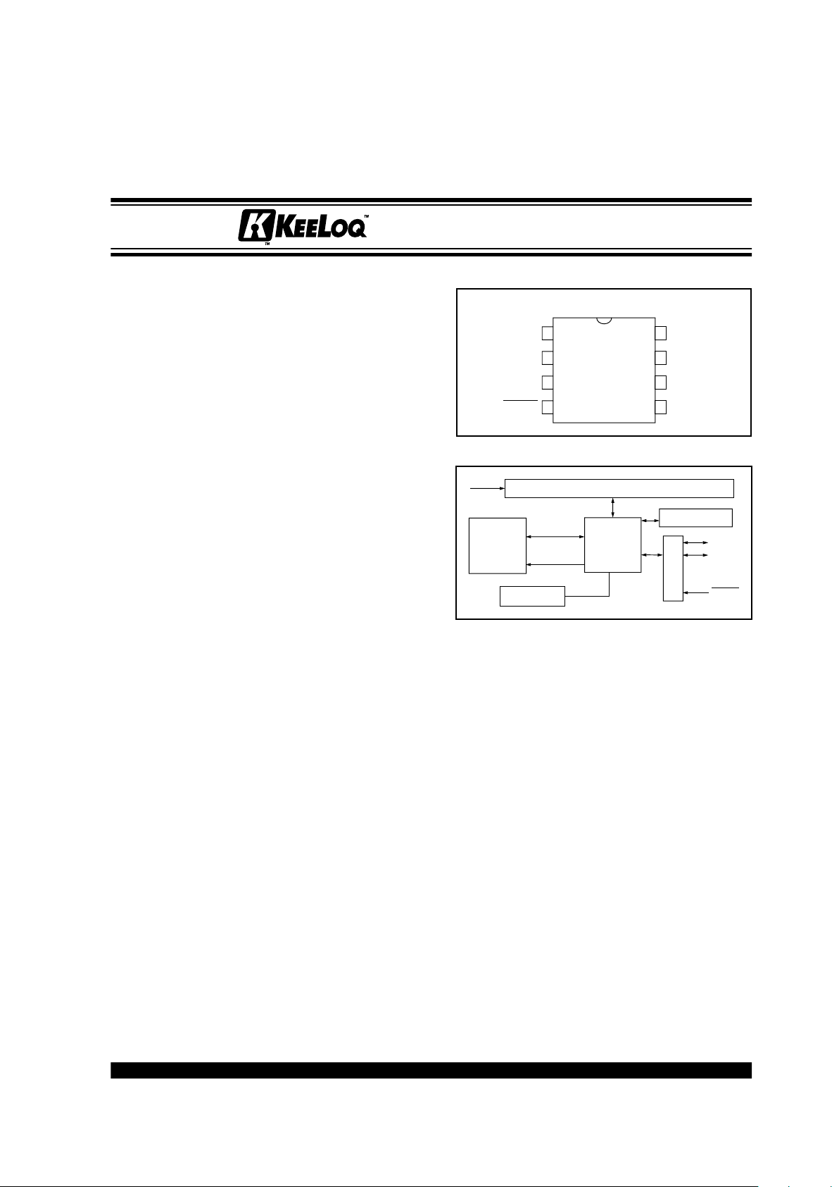
PACKA GE TYPE
BLOCK DIAGRAM
The manufacturer’s code, encoder keys, and synchronization information are stored in encrypted form in
external EEPROM. The HCS500 uses the S_DAT and
S_CLK inputs to communicate with a host controller
device.
The HCS500 operates over a wide voltage range of
3.0 volts to 5.5 volts. The decoder employs automatic
bit-rate detection, which allows it to compensate for
wide variations in transmitter data rate. The decoder
contains sophisticated error checking algorithms to
ensure only valid codes are accepted.
HCS500
PDIP, SOIC
1
2
3
4
V
DD
EE_CLK
EE_DAT
MCLR
8
7
6
5
VSS
RFIN
S_CLK
S_DAT
67-bit Reception Register
External
CONTROL
DECRYPTOR
RFIN
OSCILLATOR
S_DAT
S_CLK
MCLR
EEPROM
EE_DAT
EE_CLK
Code Hopping Decoder
K
EE
L
OQ
is a registered trademark of Microchip Technology Inc.
*Code hopping patents issued in Europe, U.S.A; and R.S.—US:5,517,187; Europe: 0459781
HCS500
DS40153B-page 2
Preliminary
1997 Microchip Technology Inc.
1.0 K
EE
L
OQ
SYSTEM OVERVIEW
1.1 K
ey Terms
• Manufacturer’s Code – A 64-bit word, unique to
each manufacturer, used to produce a unique
encoder key in each transmitter.
• Encoder Key – A 64-bit key, unique for each transmitter. The encoder key controls the KeeLoq
decryption algorithm and is stored in EEPROM on
the decoder device.
• Learn – The receiver uses information that is
transmitted to derive the transmitter’ s encoder key,
decrypt the discrimination value, and the synchronization counter in learning mode. The encoder
key is a function of the manufacturer’s code and
the device serial number and/or seed value.
The HCS encoders and decoders employ the KeeLoq
code hopping technology and a KeeLoq encryption
algorithm to achieve a high level of security. Code
hopping is a method by which the code transmitted
from the transmitter to the receiver is different every
time a button is pushed. This method, coupled with a
transmission length of 66 bits, virtually eliminates the
use of code ‘grabbing’ or code ‘scanning’.
1.2 HCS E
ncoder Overview
The HCS encoders have a small EEPR OM array which
must be loaded with several parameters before use.
The most important of these values are:
• An encoder key that is generated at the time of
production
• A 16-bit synchronization counter value
• A 28-bit serial number which is meant to be
unique for every encoder
The manufacturer programs the serial number for each
encoder at the time of production, while the ‘Key Generation Algorithm’ generates the encoder k ey (Figure 1-
1). Inputs to the key generation algorithm typically con-
sist of the encoder’s serial number and a 64-bit manufacturer’s code, which the manufacturer creates.
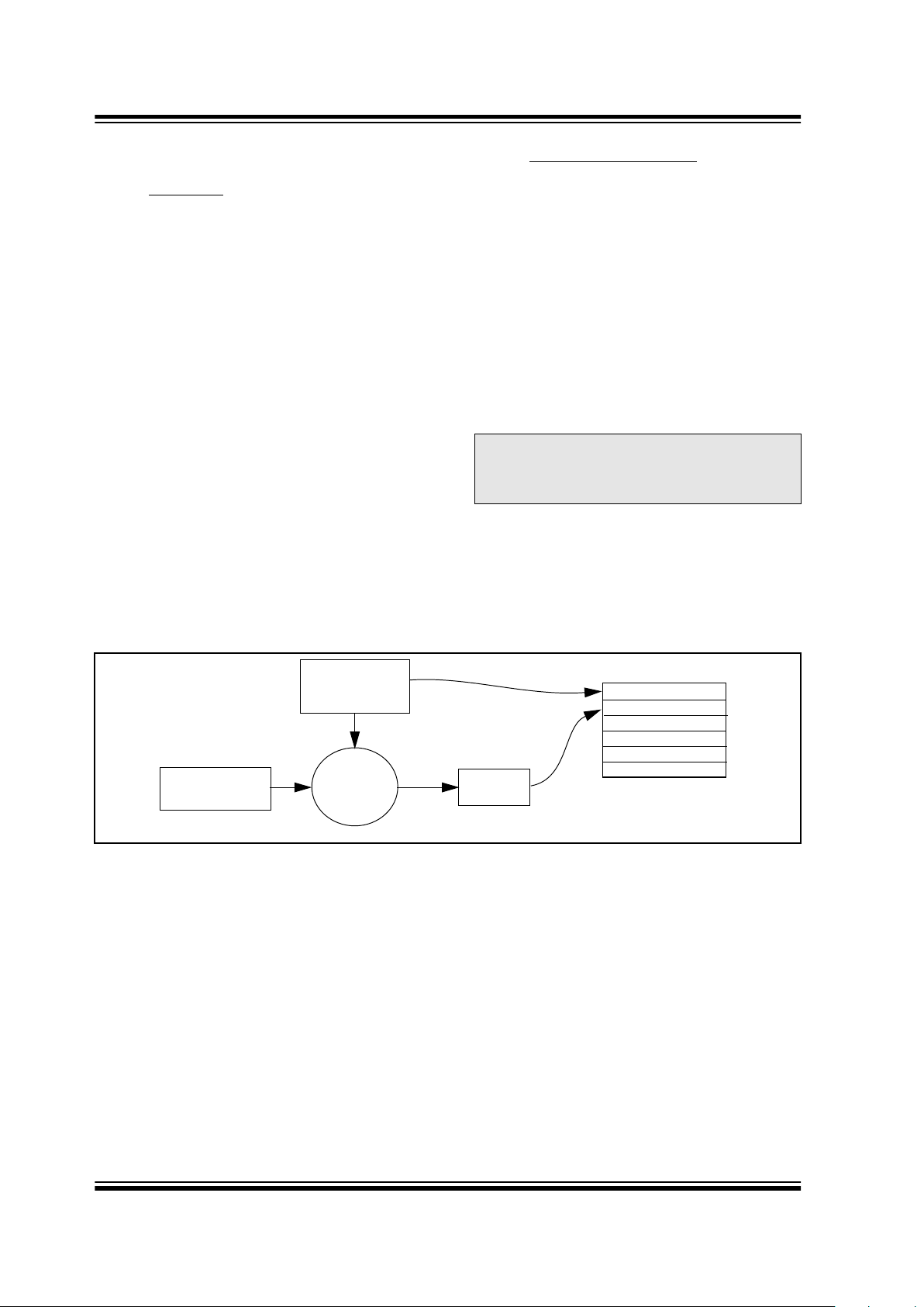
FIGURE 1-1: CREATION AND STORAGE OF ENCRYPTION KEY DURING PRODUCTION
Note: The manufacturer code is a pivotal part of
the system’s overall security. Consequently, all possible precautions must be
taken and maintained for this code.
Transmitter
Manufacturer’s
Serial Number or
Code
Encryption
Key
Key
Generation
Algorithm
Serial Number
Encryption Key
Sync Counter
.
.
.
HCS500 EEPROM Array
Seed
HCS500
1997 Microchip Technology Inc.
Preliminary
DS40153B-page 3
The 16-bit synchronization counter is the basis for the
transmitted code changing for each transmission and is
updated each time a button is pressed. Because of the
complexity of the K
EE
L
OQ
encryption algorithm, a
change in one bit of the synchronization counter value
will result in a large change in the actual transmitted
code. There is a relationship (Figure 1-2) between the
encoder key values in EEPROM and how they are used
in the encoder. Once the encoder detects that a b utton
has been pressed, the encoder reads the button and
updates the synchronization counter. The synchronization value is then combined with the encoder key in the
K
EE
L
OQ
encryption algorithm, and the output is 32 bits
of encrypted information. This data will change with
every button press, hence, it is referred to as the code
hopping portion of the code word. The 32-bit code hopping portion is combined with the button information
and the serial number to form the code word transmitted to the receiver.
1.3 HCS D
ecoder Overview
Before a transmitter and receiver can work together , the
receiver must first ‘lear n’ and store certain information
from the transmitter. This information includes a ‘check
value’ of the ser ial number, the encoder key, and current synchronization counter value.
When a validly formatted message is detected, the
receiver first compares the serial number. If the serial
number check value is from a learned transmitter, the
message is decrypted. Next, the receiver checks the
decrypted synchronization counter value against what
is stored in memory. If the synchronization counter
value is verified, then a valid transmission message is
sent. Figure 1-3 shows the relationship between some
of the values stored by the receiver and the values
received from the transmitter.
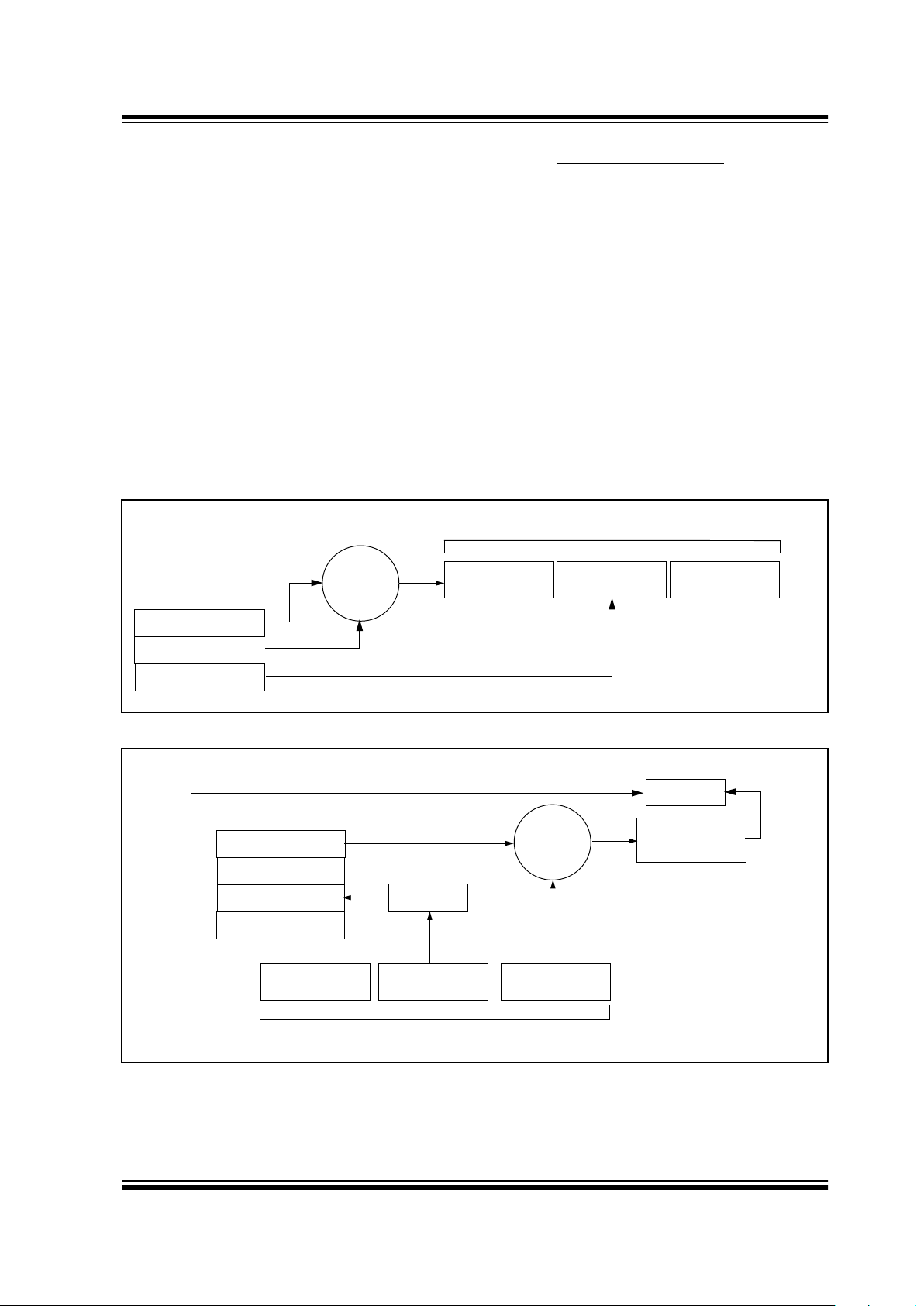
FIGURE 1-2: BASIC OPERATION OF A CODE HOPPING TRANSMITTER (ENCODER)
FIGURE 1-3: BASIC OPERATION OF A CODE HOPPING RECEIVER (DECODER)
KEELOQ
Algorithm
Button Press
Information
Encryption
EEPROM Array
32 Bits of
Encrypted Data
Serial Number
Transmitted Information
Encoder Key
Sync. Counter Value
Serial Number
Button Press
Information
EEPROM Array
Encoder Key
32 Bits of
Encrypted Data
Serial Number
Received Information
Decrypted
Synchronization
Counter
Check for
Match
Check for
Match
KEELOQ
Algorithm
Decryption
Sync. Counter Value
Serial Number
Manufacturer Code
HCS500
DS40153B-page 4
Preliminary
1997 Microchip Technology Inc.
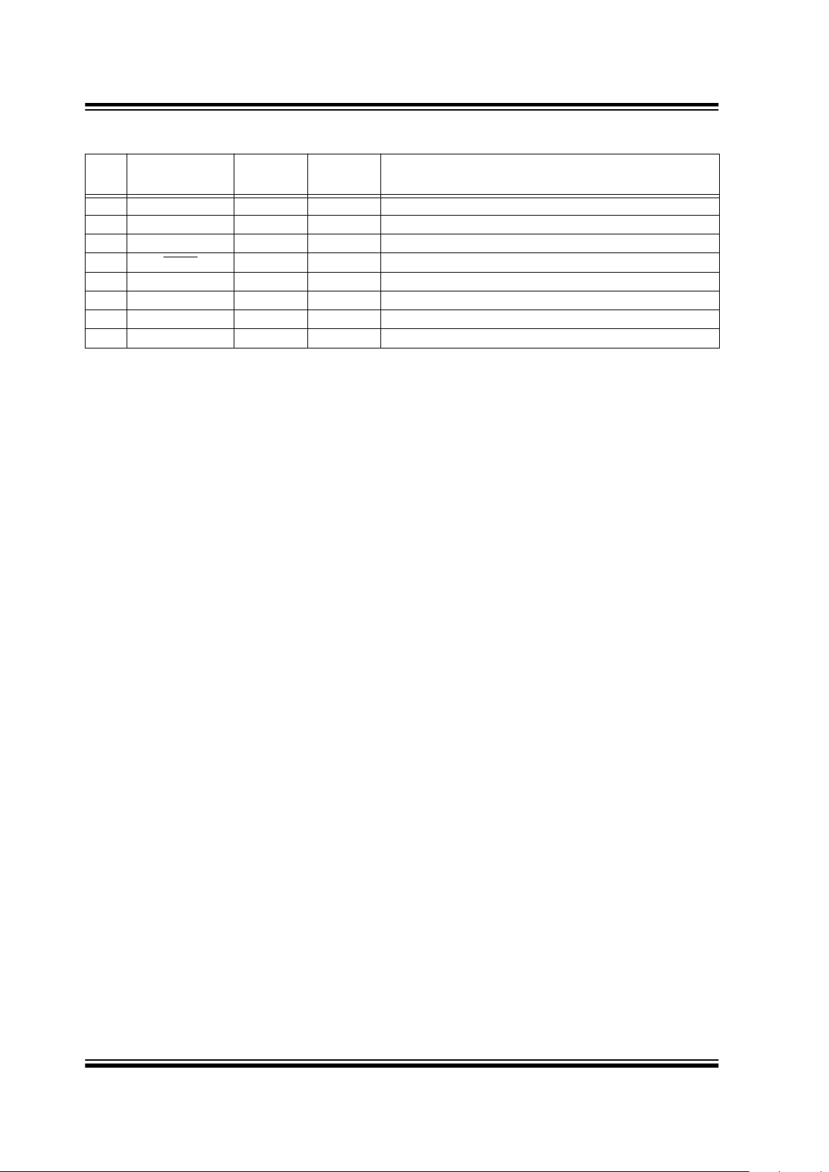
2.0 PIN ASSIGNMENT
PIN
Decoder
Function
I/O
(1)
Buffer
Type
(1)
Description
1 V
DD
P — Power Connection
2 EE_CLK O TTL Clock to I
2
C
™
EEPROM
3 EE_DAT I/O TTL Data to I
2
C EEPROM
4 MCLR
I ST Master clear input
5 S_DAT I/O TTL Synchronous data from controller
6 S_CLK I TTL Synchronous clock from controller
7 RFIN I TTL RF input from receiver
8 GND P — Ground connection
Note: P = power, I = in, O = out, and ST = Schmitt Trigger input.
I
2
C is a trademark of Philips Corporation.
HCS500
1997 Microchip Technology Inc.
Preliminary
DS40153B-page 5
3.0 DECODER OPERATION
3.1 Learning a
Transmitter to a Receiver
(Normal or Secure Learn)
Before the transmitter and receiver can work together,
the receiver must first ‘learn’ and store the following
information from the transmitter in EEPROM:
• A check value of the serial number
• The encoder key
• The current synchronization counter value
The decoder must also store the manufacturer’s code
(Section 1.2) in protected memory. This code will
typically be the same for all of the decoders in a system.
The HCS500 has seven memory slots, and, consequently, can store up to seven transmitters. During the
learn procedure, the decoder searches for an empty
memory slot for storing the transmitter’s information.
When all of the memory slots are full, the decoder will
overwrite the last transmitter’s information. To erase all
of the memory slots at once, use the ERASE_ALL command (C3H).
3.1.1 LEARNING PROCEDURE
Learning is initiated by sending the ACTIVATE_LEARN
(D2H) command to the decoder. The decoder acknowledges reception of the command by pulling the data
line high.
For the HCS500 decoder to learn a new transmitter , the
following sequence is required:
1. Activate the transmitter once.
2. Activate the transmitter a second time. (In
secure learning mode, the seed transmission
must be transmitted during the second stage of
learn by activating the appropriate buttons on
the transmitter.)
The HCS500 will transmit a lear n-status string,
indicating that the learn was successful.
3. The decoder has now learned the transmitter.
4. Repeat steps 1-3 to learn up to seven
transmitters
Note 1: Learning will be terminated if two
nonsequential codes were received or if two
acceptable codes were not decoded within
30 seconds.
2:
If more than seven transmitters are learned,
the new transmitter will replace the last
transmitter learned. It is, therefore, not possible to erase lost transmitters by
repeatedly learning new transmitters. To
remove lost or stolen transmitters,
ERASE_ALL transmitters and relearn all
available transmitters.
3:
Learning a transmitter with an encoder key
that is identical to a transmitter already in
memory replaces the existing transmitter. In
practice, this means that all transmitters
should have unique encoder ke ys. Learning
a previously learned transmitter does not
use any additional memory slots.
The following checks are perfor med by the decoder to
determine if the transmission is valid during learn:
• The first code word is checked for bit integrity.
• The second code word is checked for bit integrity.
• The encoder key is generated according to the
selected algorithm.
• The hopping code is decrypted.
• The discrimination value is checked.
• If all the checks pass, the key, serial number
check value, and synchronization counter values
are stored in EEPROM memory.
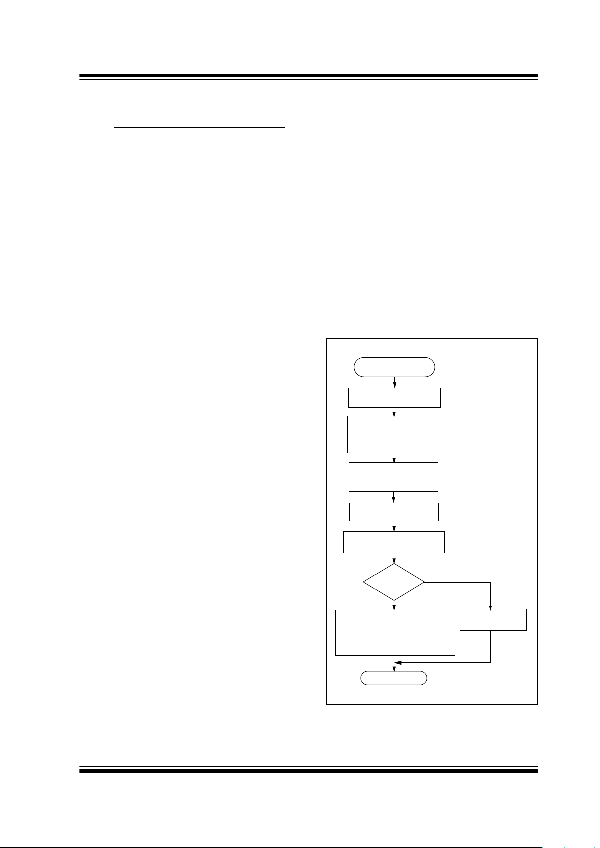
Figure 3-1 shows a flow chart of the learn sequence.
FIGURE 3-1: LEARN SEQUENCE
Enter Learn
Mode
Wait for Reception
of Second
Compare Discrimination
Value with Serial Number
Use Generated Key
to Decrypt
Equal?
Sync. counter value
Encoder key
Exit
Learn successful. Store:
Learn
Unsuccessful
No
Yes
Wait for Reception
of a Valid Code
Non-Repeated
Valid Code
Generate Key
from Serial Number/
Seed Value
Serial number check value
HCS500
DS40153B-page 6
Preliminary
1997 Microchip Technology Inc.
3.2 V
alidation of Codes
The decoder waits for a transmission and checks the
serial number to determine if it is a learned transmitter.
If it is, it takes the code hopping portion of the transmission and decrypts it, using the encoder key. It uses the
discrimination value to determine if the decryption was
valid. If everything up to this point is valid, the
synchronization counter value is evaluated.
3.3 V
alidation Steps
Validation consists of the following steps:
1. Search EEPROM to find the Serial Number
Check Value Match
2. Decrypt the Hopping Code
3. Compare the 10 bits of the discrimination value
with the lower 10 bits of serial number
4. Check if the synchronization counter value falls
within the first synchronization window.
5. Check if the synchronization counter value falls
within the second synchronization window.
6. If a valid transmission is found, update the
synchronization counter, else use the next
transmitter block, and repeat the tests.
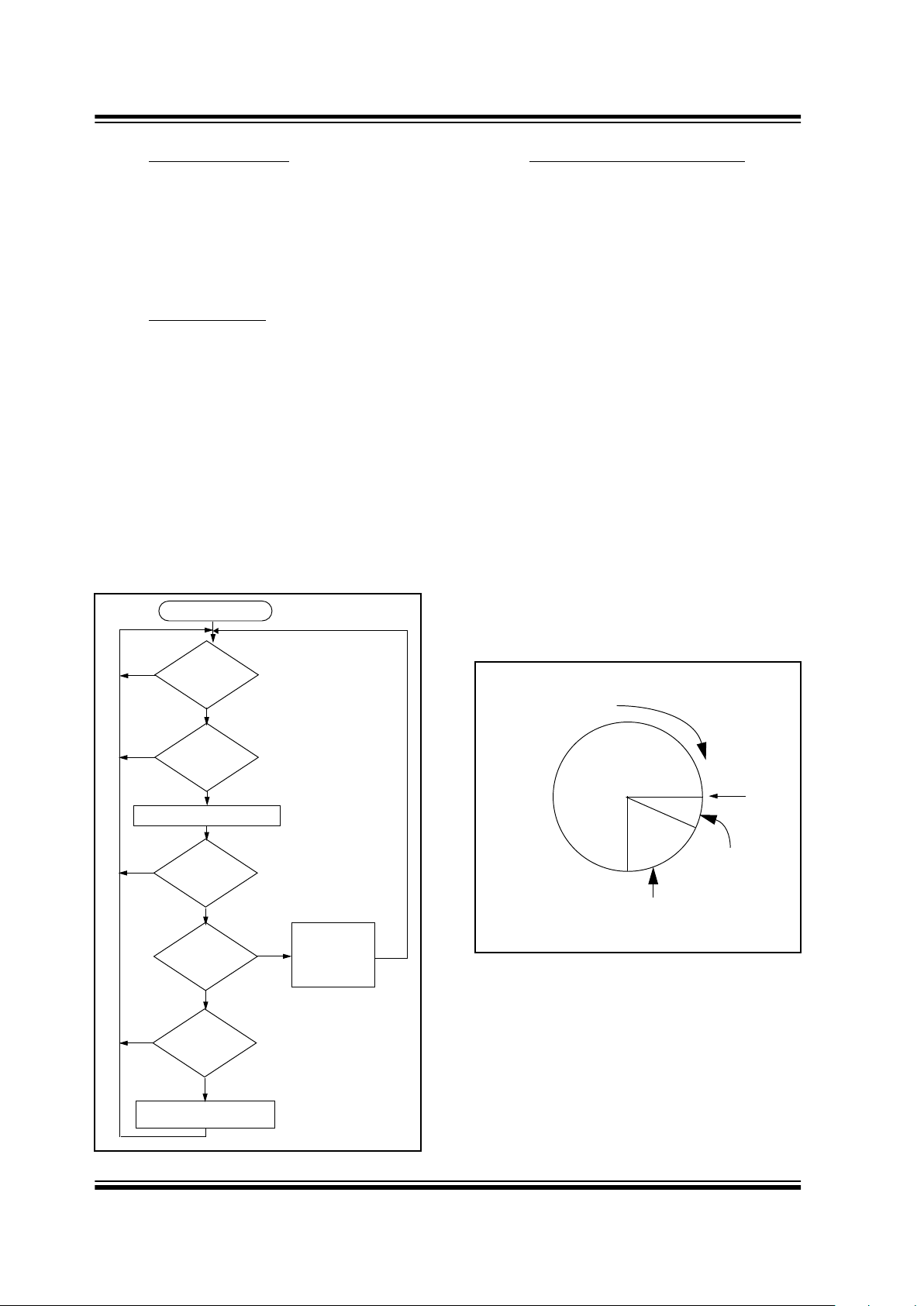
FIGURE 3-2: DECODER OPERATION
3.4 Sync
hronization with Decoder
The K
EE
L
OQ
technology features a sophisticated
synchronization technique (Figure 3-3) which does not
require the calculation and storage of future codes. If
the stored synchronization counter value for that
particular transmitter and the synchronization counter
value that was just decrypted are within a formatted
window of 16, the counter is stored, and the command
is executed. If the synchronization counter value was
not within the single operation window, but is within the
double operation window of the 16K window, the
transmitted synchronization counter value is stored in a
temporary location, and the decoder goes back to waiting for another transmission. When the next valid
transmission is received, it will check the new
synchronization counter value with the one in temporary storage. If the two values are sequential, it is
assumed that the counter had just gotten out of the
single operation ‘windo w’, but is no w bac k in synchronization, so the new synchronization counter value is
stored, and the command is executed. If a transmitter
has somehow gotten out of the double operation
window, the transmitter will not work and must be
relearned. Since the entire window rotates after each
valid transmission, codes that hav e been used become
part of the ‘blocked’ (48K) codes and are no longer
valid. This eliminates the possibility of grabbing a previous code and retransmitting to gain entry.
FIGURE 3-3: SYNCHRONIZATION WINDOW
Transmission
Received?
Does
Ser # Check Val
Match?
Decrypt Transmission
Is
decryption
valid?
Is
counter within
16?
Is
counter within
16K?
Update
Counter
Execute
Command
Save Counter
in Temp Location
Start
No
No
No
No
Yes
Yes
Yes
Yes
Yes
No
and
Blocked
Entire Window
rotates to eliminate
use of previously
used codes
Current
Position
(48K Codes)
Double
Operation
(16K Codes)
Single
Operation
Window
(16 Codes)
HCS500
1997 Microchip Technology Inc.
Preliminary
DS40153B-page 7
4.0 INTERFACING TO A
MICROCONTROLLER
The HCS500 interfaces to a microcontroller via a synchronous serial interface. A clock and data line are
used to communicate with the HCS500. The microcontroller controls the clock line. There are two groups of
data transfer messages. The first is from the decoder
whenever the decoder receives a valid transmission.
The decoder signals reception of a valid code by taking
the data line high (maximum of 500 ms) The microcontroller then services the request by clocking out a data
string from the decoder. The data string contains the
function code, the status bit, and block indicators. The
second is from the controlling microcontroller to the
decoder in the form of a defined command set.
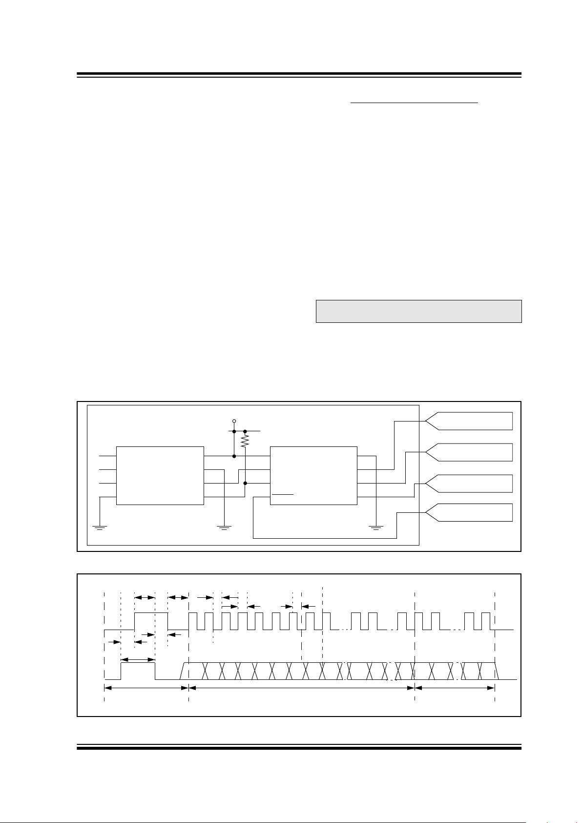
Figure 4-1 shows the HCS500 decoder and the I/O
interface lines necessary to interface to a microcontroller.
4.1 V
alid Transmission Message
The decoder informs the microcontroller of a valid
transmission by taking the data line high for up to
500 ms. The controlling microcontroller must acknowledge by taking the clock line high. The decoder then
takes the data line low. The microcontroller can then
begin clocking a data stream out of the HCS500. The
data stream consists of:
• Start bit ‘0’.
• 2 status bits [REPEAT, VLOW].
• 4-bit function code [S3 S2 S1 S0].
• Stop bit ‘1’.
• 4 bits indicating which block was used
[TX3…TX0].
• 4 bits indicating the number of transmitters
learned into the decoder [CNT3…CNT0].
• 64 bits of the received transmission with the hopping code decrypted.
The decoder will terminate the transmission of the data
stream at any point where the clock is kept low for
longer than 1 ms.Therefore, the microcontroller can
only clock out the required bits. A maximum of 80 bits
can be clocked out of the decoder.
FIGURE 4-1: HCS500 DECODER AND I/O INTERFACE LINES
FIGURE 4-2: DECODER VALID TRANSMISSION MESSAGE
Note: Data is always clocked in/out Least
Significant Bit (LSB) first.
A0
A1
A2
Vss
24LC02
Vcc
WP
SCL
SD
1
2
3
4
8
7
6
5
VDD
EE_CLK
EE_DAT
MCLR
Vss
RFIN
S_CLK
S_DAT
1
2
3
4
8
7
6
5
VDD
RF RECEIVER
SYNC CLOCK
SYNC DATA
MICRO RESET
HCS500
1K
Decoder Signal Valid
TCLKH TDS
A B Cii
TPP3
TDHI
TCLA
Received String
Ci
S_DAT
TX0 TX3 RX63REPT VLOW S0 S1 S2 S3 CNT0 CNT30 RX0 RX1 RX621
S_CLK
Information
TPP1
TCLKH
TCLKL
Transmission
HCS500
DS40153B-page 8
Preliminary
1997 Microchip Technology Inc.
4.2 C
ommand Mode
4.2.1 MICROCONTROLLER COMMAND MODE
ACTIVATION
The microcontroller command consists of four parts.
The first part activates the command mode, the second
part is the actual command, the third is the address
accessed, and the last part is the data. The microcontroller starts the command by taking the clock line high
for up to 500 ms. The decoder acknowledges the startup sequence by taking the data line high. The microcontroller takes the clock line low, after which the
decoder will take the data line low , tri-state the data line
and wait for the command to be clock in. The data must
be set up on the rising edge and will be sampled on the
falling edge of the clock line.
4.2.2 COLLISION DETECTION
The HCS500 uses collision detection to prevent
clashes between the decoder and microcontroller.
Whenever the decoder receives a valid transmission
the following sequence is followed:
• The decoder first checks to see if the clock line is
high. If the clock line is high, the valid transmission notification is aborted, and the microcontroller command mode request is serviced.
• The decoder takes the data line high and checks
that the clock line doesn’t go high within 50 µ s . If
the clock line goes high, the valid transmission
notification is aborted and the command mode
request is serviced.
• If the clock line goes high after 50 µ s but before
500 ms, the decoder will acknowledge by taking
the data line low.
• The microcontroller can then start to clock out the
80-bit data stream of the received transmission.
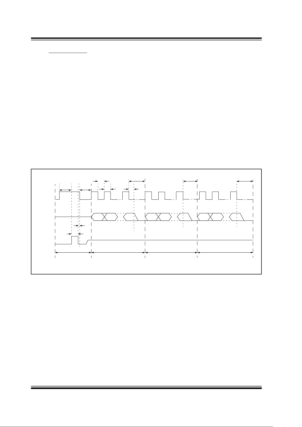
FIGURE 4-3: MICROCONTROLLER COMMAND MODE ACTIVATION
MSB
A
Command ByteStart Command
T
CLKL
TCLKH
TDS
B C
LSB
TSTART
TCMD
D
TDATA
E
Address Byte Data Byte
TADDR
TREQ
TRESP
CLK
µC Data
HCS500
Data
MSBLSB MSBLSB
TACK
 Loading...