

Datasheet MIC803-26D2VC3, MIC803-26D2VM3, MIC803-26D3VC3, MIC803-26D3VM3, MIC803-26D4VC3 Datasheet (Micrel) [ru]
...
August 3, 2015
V
CC
100k
V
CC
RESET
V
CC
µPMIC803
GND
GND
RESET
General Description
MIC803
3-Pin Microprocessor Supervisor Circuit
with Open-Drain Reset Output
Features
The MIC803 is a single-vol tage supervisor with open-drain
reset output that provides accurate power supply
monitoring and reset generation in microprocessor-based
systems. The function of the device is to assert a reset
signal if the power supply voltage drops below the reset
threshold voltage, and retain this reset for the reset
timeout period once the po wer suppl y increases abo ve the
reset threshold voltage.
The MIC803 consumes only 4.5µA of supply current and
offers three reset delay periods of 20ms, 140ms, and
1120ms (minimum). It features factory-programmed reset
threshold levels from 2.63V to 4.63V to accommodate
3.0V, 3.3V, and 5.0 V power supplies. It is available in the
compact 3-pin SC-70 and SOT-23 packages.
Datasheets and support documentation are available on
Micrel’s web site at: www.micrel.com
.
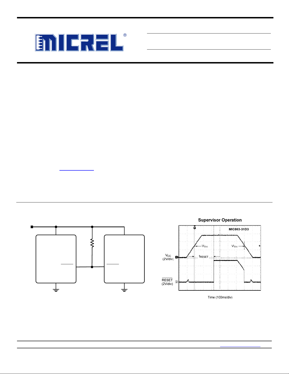
Typical Application
• 4.5μA supply current (typical) at 3.6V
• Open-drain /RESET output
• /RESET remains valid with V
as low as 1V
CC
• 20ms, 140ms, or 1120ms (minimum) reset timeout
options
• 2.63V to 4.63V preset voltage threshold options
• 2.5% voltage threshold accuracy over temperature
• 3-pin SC70-3 package (2.0mm × 2.1mm)
• 3-pin SOT-23 package (2.3mm × 2.9mm)
• -40˚C to +125˚C junction temperature range
Applications
• Critical microcomputer power monitoring
• Portable equipment
• Solid state drives
• Printers/computers
• Embedded controllers
Micrel Inc. • 2180 Fortune Drive • San Jose, CA 95131 • USA • tel +1 (408) 944-0800 • fax + 1 (408) 474-1000 • http://www.micrel.com
Revision 1.2

Micrel, Inc.
MIC803
August 3, 2015
Ordering Information
(1)
Part Number Marking
(2)
Nominal
V
(V)
TH
Minimum
(3)
t
RESET
(ms)
Junction Temperature Range Package
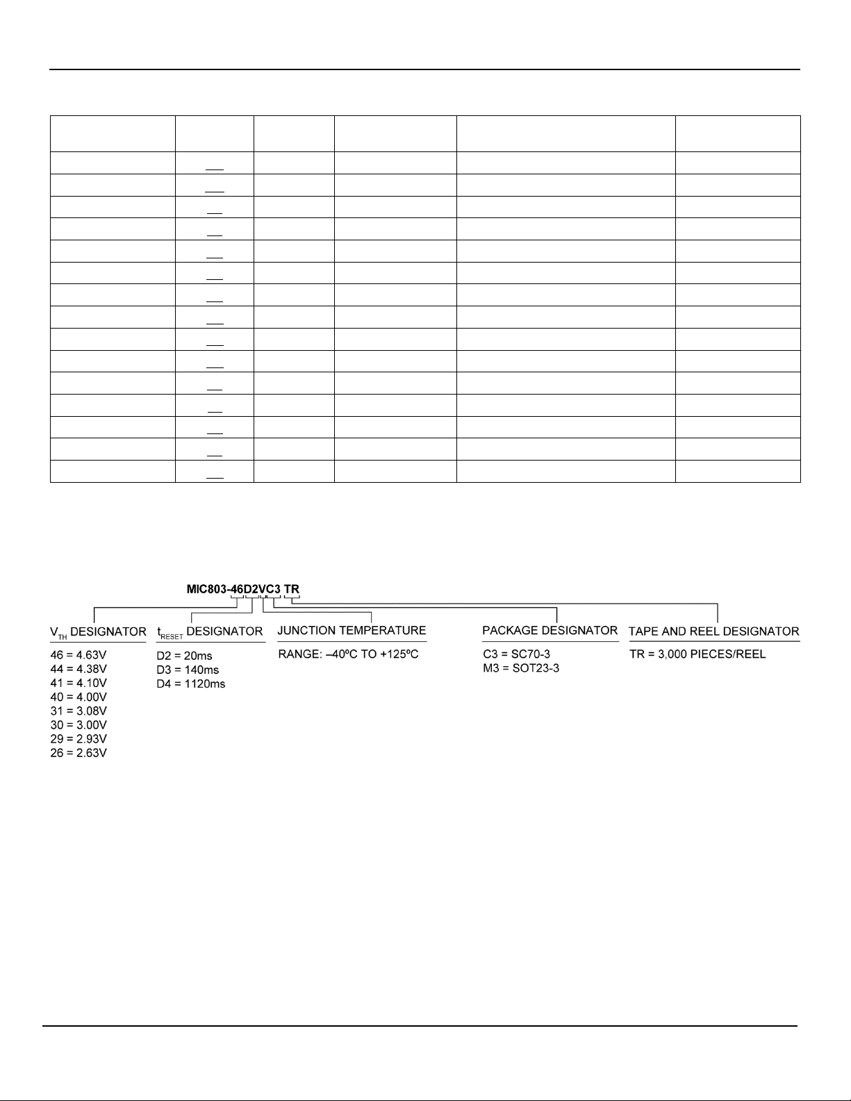
MIC803-46D2VC3 AS 4.63 20 –40° to +125°C SC70-3
MIC803-44D2VC3 AP 4.38 20 –40° to +125°C SC70-3
MIC803-41D2VC3 AK 4.10 20 –40° to +125°C SC70-3
MIC803-40D2VC3 A2 4.00 20 –40° to +125°C SC70-3
MIC803-31D2VC3 AG 3.08 20 –40° to +125°C SC70-3
MIC803-30D2VC3 AV 3.00 20 –40° to +125°C SC70-3
MIC803-29D2VC3 AD 2.93 20 –40° to +125°C SC70-3
MIC803-26D2VC3 AA 2.63 20 –40° to +125°C SC70-3
MIC803-46D3VC3 AT 4.63 140 –40° to +125°C SC70-3
MIC803-44D3VC3 AQ 4.38 140 –40° to +125°C SC70-3
MIC803-41D3VC3 AM 4.10 140 –40° to +125°C SC70-3
MIC803-40D3VC3 A5 4.00 140 –40° to +125°C SC70-3
MIC803-31D3VC3 A4 3.08 140 –40° to +125°C SC70-3
MIC803-30D3VC3 AX 3.00 140 –40° to +125°C SC70-3
MIC803-29D3VC3 AE 2.93 140 –40° to +125°C SC70-3
MIC803-26D3VC3 AB 2.63 140 –40° to +125°C SC70-3
MIC803-46D4VC3 AU 4.63 1120 –40° to +125°C SC70-3
MIC803-44D4VC3 AR 4.38 1120 –40° to +125°C SC70-3
MIC803-41D4VC3 AN 4.10 1120 –40° to +125°C SC70-3
MIC803-40D4VC3 A6 4.00 1120 –40° to +125°C SC70-3
MIC803-31D4VC3 AJ 3.08 1120 –40° to +125°C SC70-3
MIC803-30D4VC3 AZ 3.00 1120 –40° to +125°C SC70-3
MIC803-29D4VC3 A3 2.93 1120 –40° to +125°C SC70-3
MIC803-26D4VC3 AC 2.63 1120 –40° to +125°C SC70-3
MIC803-46D2VM3 AS 4.63 20 –40° to +125°C SOT23-3
MIC803-44D2VM3 AP 4.38 20 –40° to +125°C SOT23-3
MIC803-41D2VM3 AK 4.10 20 –40° to +125°C SOT23-3
MIC803-40D2VM3 A2 4.00 20 –40° to +125°C SOT23-3
MIC803-31D2VM3 AG 3.08 20 –40° to +125°C SOT23-3
MIC803-30D2VM3 AV 3.00 20 –40° to +125°C SOT23-3
MIC803-29D2VM3 AD 2.93 20 –40° to +125°C SOT23-3
MIC803-26D2VM3 AA 2.63 20 –40° to +125°C SOT23-3
MIC803-46D3VM3 AT 4.63 140 –40° to +125°C SOT23-3
Note:
1. All devices available in tape and reel only. (Order entry PN, add TR. Example: MIC803-26D4VM3 TR)
Standard/full reel quantity is 3,000 pieces.
Reel diameter is 7 inches. Hub diameter is 2 inches. Width is 8mm.
2. Underbar symbol (_) may not be to scale.
3. –40° to +85°C temperature range.
2
Revision 1.2
Micrel, Inc.
MIC803
August 3, 2015
Ordering Information
(1)
(Continued)
Nominal
Part Number Marking
MIC803-44D3VM3 AQ 4.38 140 –40° to +125°C SOT23-3
MIC803-41D3VM3 AM 4.10 140 –40° to +125°C SOT23-3
MIC803-40D3VM3 A5 4.00 140 –40° to +125°C SOT23-3
MIC803-31D3VM3 A4 3.08 140 –40° to +125°C SOT23-3
MIC803-30D3VM3 AX 3.00 140 –40° to +125°C SOT23-3
MIC803-29D3VM3 AE 2.93 140 –40° to +125°C SOT23-3
MIC803-26D3VM3 AB 2.63 140 –40° to +125°C SOT23-3
MIC803-46D4VM3 AU 4.63 1120 –40° to +125°C SOT23-3
MIC803-44D4VM3 AR 4.38 1120 –40° to +125°C SOT23-3
MIC803-41D4VM3 AN 4.10 1120 –40° to +125°C SOT23-3
MIC803-40D4VM3 A6 4.00 1120 –40° to +125°C SOT23-3
MIC803-31D4VM3 AJ 3.08 1120 –40° to +125°C SOT23-3
MIC803-30D4VM3 AZ 3.00 1120 –40° to +125°C SOT23-3
MIC803-29D4VM3 A3 2.93 1120 –40° to +125°C SOT23-3
MIC803-26D4VM3 AC 2.63 1120 –40° to +125°C SOT23-3
(2)
(V)
V
TH
Minimum
(3)
t
RESET
(ms)
Junction Temperature Range Package
Part Numbering Convention
3
Revision 1.2
Micrel, Inc.
MIC803
August 3, 2015
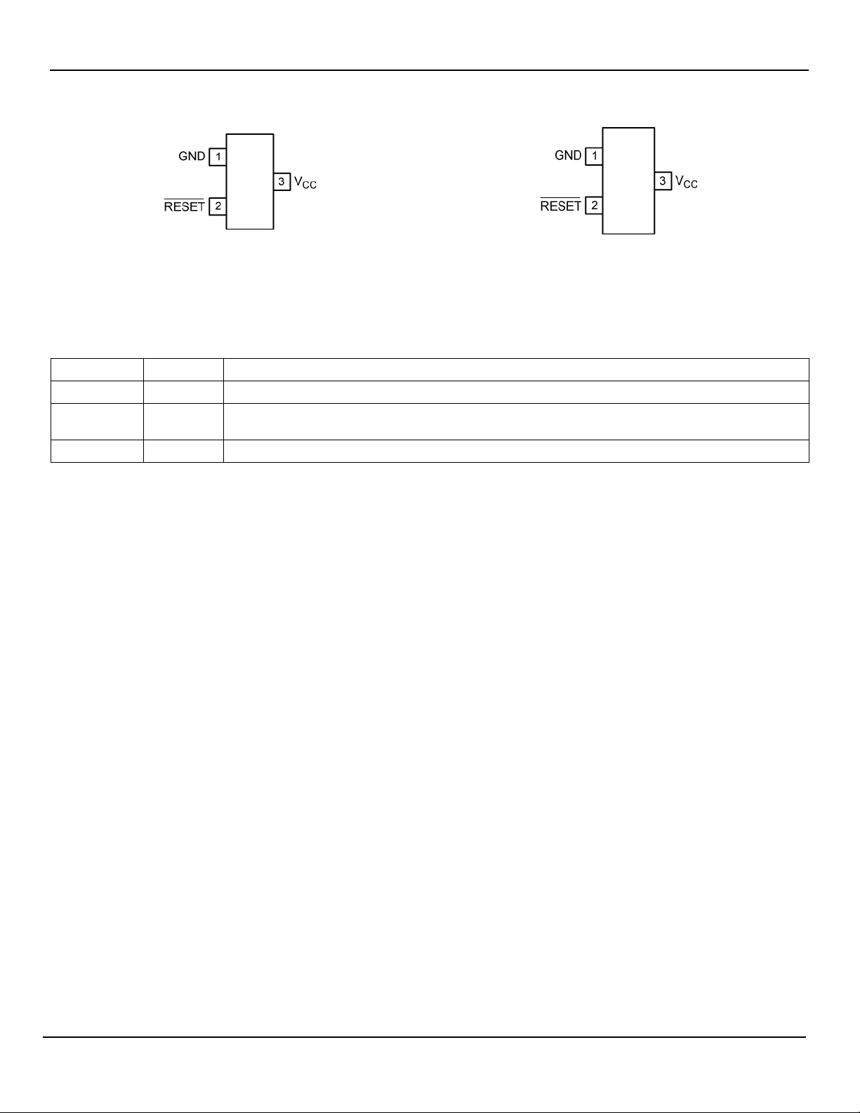
(Top View)
(Top View)
Pin Configuration
3-Pin SC70
Pin Description
Pin Number Pin Name Pin Function
1 GND Ground Pin.
2 /RESET
3 VCC Power Supply Input and Monitored Voltage.
/RESET goes low if VCC falls below the reset threshold (VTH), and remains asserted for one timeout
period after V
exceeds VTH.
CC
3-Pin SOT-23
4
Revision 1.2

Micrel, Inc.
MIC803
August 3, 2015
Absolute Maximum Ratings
(4)
Supply Voltage (VCC) ...................................... –0.3V to 6.0V
Reset Output (/RESET) .................................. –0.3V to 6.0V
Input Current (V
) ...................................................... 20mA
CC
Output Current (/RESET) ............................................ 20mA
Rate of Rise (V
Junction Temperature (T
) ................................................... 100V/µs
CC
)…………………………....+150°C
J
Lead Temperature (soldering, 10s) ............................ 260°C
Storage Temperature (T
ESD Rating
(6)
.................................................................. 3kV
) ......................... –65°C to +150°C
S
Operating Ratings
(5)
Supply Voltage (VCC) ........................................ 1.0V to 5.5V
Reset Output Voltage (/RESET) ...................... 0.0V to 5.5V
Junction Temperature (T
) ........................ –40°C to +125°C
J
Junction Thermal Resistance
3-Pin SC70 (θ
3-Pin SOT-23 (θ
) .............................................. 260°C/W
JA
) ........................................... 203°C/W
JA
Electrical Characteristics
For typical values, V
Bold values indicate –40°C ≤ T
Parameter Conditions Min. Typ. Max. Units
Power Supply Input
Operating Voltage Range (VCC)
Supply Current (ICC)
Voltage Threshold
Reset Threshold (VTH)
Notes:
4. Exceeding the absolute maximum ratings may damage the device.
5. The device is not guaranteed to function outside its operating ratings.
6. Devices are ESD sensitive. Handling precautions are recommended. Human body model, 1.5kΩ in series with 100pF.
7. Specification for packaged product only.
= 5.0V for MIC803-46/44/41/40, VCC = 3.3V for MIC803-31/30/29, VCC = 3.0V for MIC803-26; TJ = 25°C,
CC
J
(7)
≤ +125°C; unless noted.
TJ = –40˚C to +85˚C 1.0 5.5
TJ = –40˚C to +125˚C 1.2 5.5
TJ = –40˚C to +85˚C
TJ = +85˚C to +125˚C
MIC803-46
MIC803-44
MIC803-41
MIC803-40
MIC803-31
VCC = 5.5V, No Load 5.5 15
VCC = 3.6V, No Load 4.5 10
VCC = 5.5V, No Load 18
VCC = 3.6V, No Load 13
TJ = –40˚C to +85˚C 4.50 4.63 4.75
TJ = –40˚C to +125˚C 4.44 4.82
TJ = –40˚C to +85˚C 4.25 4.38 4.50
TJ = –40˚C to +125˚C 4.20 4.56
TJ = –40˚C to +85˚C 4.00 4.10 4.20
TJ = -40˚C to +125˚C 3.97 4.24
TJ = –40˚C to +85˚C 3.89 4.00 4.10
TJ = –40˚C to +125˚C 3.80 4.20
TJ = –40˚C to +85˚C 3.00 3.08 3.15
TJ = –40˚C to +125˚C 2.95 3.21
µA
V
V
5
Revision 1.2

Micrel, Inc.
MIC803
August 3, 2015
Electrical Characteristics
(7)
(Continued)
For typical values, V
Bold values indicate –40°C ≤ TJ ≤ +125°C; unless noted.
Parameter Conditions Min. Typ. Max. Units
Voltage Threshold (Continued)
Reset Threshold (VTH)
Reset Time
VCC to /RESET Delay (tD) VCC = VTH to (VTH – 100mV) 15 µs
Reset Timeout Period (t
Reset Output
/RESET Output Voltage (VOL)
/RESET Output Leakage VCC > VTH, /RESET Deasserted
= 5.0V for MIC803-46/44/41/40, VCC = 3.3V for MIC803-31/30/29, VCC = 3.0V for MIC803-26; TJ = 25°C,
CC
TJ = –40˚C to +85˚C 2.93 3.00 3.08
TJ = –40˚C to +125˚C 2.90 3.11
TJ = –40˚C to +85˚C 2.82 2.93 3.00
TJ = –40˚C to +125˚C 2.81 3.05
TJ = –40˚C to +85˚C 2.55 2.63 2.70
TJ = –40˚C to +125˚C 2.50 2.76
TJ = –40˚C to +85˚C 20 35 44
TJ = –40˚C to +125˚C 16 48
TJ = –40˚C to +85˚C 140 230 360
TJ = –40˚C to +125˚C 112 420
TJ = –40˚C to +85˚C 1120 1800 2400
TJ = –40˚C to +125˚C 900 3200
0.4
0.3
0.3
1
RESET
)
MIC803-30
MIC803-29
MIC803-26
D2
D3
D4
VCC ≥ 4.0V, I
VCC > 2.5V, I
VCC ≥ 1.0V, I
= 3.2mA
SINK
= 1.2mA
SINK
= 50µA
SINK
ms
μA
V
V
V
V
6
Revision 1.2

Micrel, Inc.
MIC803
August 3, 2015
V
CC
Operating Supply Current
vs. Temperature
3
4
5
6
7
-50 -20 10 40 70 100 130
TEMPERATURE ( °C)
SUPPLY CURRENT ( µ A)
V
CC
= 3.6V
V
CC
to /RESET Delay
vs. Temperature
0
5
10
15
20
25
30
-50
-20
10 40 70 100 130
TEMPERATURE (
°C)
V
CC
to /RESET DELAY ( µs)
V
CC
= V
TH
to V
TH
-100mV
Reset Timeou t Period ( D3)
vs. Temperature
200
220
240
260
280
300
-50
-20 10 40 70 100 130
TEMPERATURE ( °C)
RESET TIMEOUT PERIO D ( m s )
V
CC
= 5.5V
Normalized R eset Threshold
vs. Temperature
0.988
0.992
0.996
1.000
1.004
-50 -20 10 40 70 100 130
TEMPERATURE ( °C)
NORMAL IZED RESET
THRESHOLD (V)
VCC Operating Supply Current
vs. Supply Voltage
0
2
4
6
8
0 1 2 3 4 5 6
SUPPLY VO LTAGE ( V)
SUPPLY CURRENT ( µ A)
VTH = 2.93V
Maximum Transient Durati on
vs Overdrive
0
10
20
30
40
50
0 200 400 600 800 1000
OVERDRIVE VO LT AGE, VTH - VCC (mV)
MAXI M UM TRANSIE NT
DURATIO N (µs)
V
TH
= 2.93V
Typical Characteristics
7
Revision 1.2

Micrel, Inc.
MIC803
August 3, 2015
V
CC
V
TH
RESET
0V
V
OL
t
RESET
t
D
t
RESET
RESET
GENERATOR
V
CC
(
3)
GND (1)
RESET (2)
MIC803
+
-
V
TH
Timing Diagram
Functional Diagram
8
Revision 1.2

Micrel, Inc.
MIC803
August 3, 2015
V
CC
100k
+3.3V
RESET
V
CC
µP
MIC803
GND
GND
RESET
+5V
Application Information
Microprocessor Reset
The /RESET pin is asserted whenever V
reset threshold voltage, V
. The /RESET pin remains
TH
falls below the
CC
asserted for the duration of the reset timeout period
) after VCC has risen above the reset threshold
(t
RESET
voltage. The res et func tion ensures the m icropr ocess or is
properly reset and po wer s up in a known c ond it ion af ter a
power failure. /RESET will remain valid with V
as low
CC
as 1.0V.
The /RESET output is a simple open-drain N-channel
MOSFET structure. A pull-up resistor must be used to
pull this output up to som e voltag e. For m os t applica tio ns ,
this voltage will be t he same power supply that s upplies
to the MIC803. As shown in Figure 1, it is possible,
V
CC
however, to tie this resistor to som e other voltage. This
will allow the MIC803 to monitor one voltag e while levelshifting the /RESET output to some other voltage. The
pull-up voltage mus t be lim ited to 5.5V. T he resis tor must
be small enough to supply current to the inputs and
leakage paths that are driven by the /RESET output.
/RESET Valid at Low Voltage
As V
drops to 0V, the MIC803 will no longer b e able to
CC
pull the /RESET o utput low, and the pull-up resistor will
pull the output high. T he value of the pu ll-up resistor and
the voltage it is c onnected to will af fect the point at which
this happens.
Figure 2. /RESET at Falling V
CC
Figure 1. MIC803 Used in a Multipl e Supply System
Wire ORing the /RESET Output
Since the /RESET output is open-drain, several reset
sources can be wire-ORed, in parallel, to allow resets
from multiple sources.
Transients
V
CC
The MIC803 is relatively immune to negative-going V
CC
glitches below the reset threshold (see Typical
Characteristics, graph titled “Maximum Transient
Duration vs. Overdrive”). As shown in Figure 3, the
overdrive voltage is the difference between th e threshold
voltage and the minimum point of the V
glitch.
CC
Typically, an overdriv e of 100mV, with duration of 15μs or
less will not caus e a r eset . If addit ion al tr ans ie nt im munity
is needed, a 0.1μF bypass capacitor can be placed as
close as possible to the MIC803 on the VCC pin.
9
Figure 3. V
Threshold
CC
Revision 1.2

Micrel, Inc.
MIC803
August 3, 2015
Package Information and Recommended Landing Pattern
(8)
Note:
8. Package information is correct as of the publication date. For updates and most current information, go to www.micrel.com
3-Pin SC70 (MM)
.
10
Revision 1.2

Micrel, Inc.
MIC803
August 3, 2015
Package Information and Recommended Landing Pattern
(8)
3-Pin SOT-23 (MM)
11
Revision 1.2

Micrel, Inc.
MIC803
August 3, 2015
MICREL, INC. 2180 FORTUNE DRIVE SAN JOSE, CA 95131 USA
Micrel, Inc. is a leading global m anufacturer of IC sol utions for the worldwide high pe
unications
markets. The Company’s products include advanced mixed
performance communication, clock
management,
Company customers
include leading manufacturers of enterprise, consumer, industrial, mobile, telecommunications, automotive, and computer produ
Corporation headquarters and state
San Jose, CA, with regional sales and support offices and
advanced technology design centers situated throughout t he Americas, Europe
, the Company maintains an extensive network
of distributors and reps worldwide.
Micrel makes no
sheet. This
information is not intended as a warranty and Micrel does not assume responsibility for its use.
change circuitry,
specifications and descriptions at any ti me without notice. No license, whether express, implied, arising by estoppel or otherwise, to any intell ectual
property rights
conditions of sale for such produc ts, Micrel assumes no liabil ity
whatsoever, and Micrel disclaims any express or implied warranty relati ng to the sale and/or use of Micrel products including liability or warranties
relating to fitness for a particular pu
Micrel Products are not designed or authorized for use as com ponents in life support appliances, devices or systems where malf unction of a product
can
nded for surgical
implant into the body or (b) support or sustain life, and whose fai l ure to perform can be reasonably expected to result in a significant injury t o t he user. A
Purchaser’s use or sale of Micrel Products for use in life support appliances, devices or systems is a Purchaser’s own risk a nd P urchaser agrees to fully
indemnify Micrel for any damages resulting from such use
TEL +1 (408) 944-0800 FAX +1 (408) 474-1000 WEB http://www.micrel.com
MEMs-based clock oscillators & crystal-less clock generators, Ethernet s witches, and physic al layer transceiver ICs.
reasonably be expected to result in personal injury. Life support devices or systems are devices or syst ems that (a) are inte
representations or warranties with respect to the accuracy or completeness of the information furnished in this data
is grant ed by this document. E xcept as provided in Micrel’s terms and
-of-the-art wafer fabrication facilities are located in
rpose, merchantability, or infringement of any patent, copyright, or other intel l ectual propert y right.
-signal, analog & power semiconductors; high-
or sale.
© 2010 Micrel, Incorporated.
12
rformance linear and power, LAN, and t iming & comm
, and Asia. Additionally
Micrel reserves the right to
Revision 1.2
cts.

 Loading...