

Page 1
Easidew DryCheck
OnLine Dew-Point Hygrometer
User’s Manual
97108 Issue 13
July 2017
Page 2

Please fi ll out the form(s) below for each instrument that has been purchased.
Use this information when contacting Michell Instruments for service purposes.
Instrument
Code
Serial Number
Invoice Date
Location of Instrument
Tag No
Instrument
Code
Serial Number
Invoice Date
Location of Instrument
Tag No
Instrument
Code
Serial Number
Invoice Date
Location of Instrument
Tag No
Page 3
Easidew DryCheck
For Michell Instruments' contact information please go to
www.michell.com
© 2017 Michell Instruments
This document is the property of Michell Instruments Ltd. and may not be copied or
otherwise reproduced, communicated in any way to third parties, nor stored in any Data
Processing System without the express written authorization of Michell Instruments Ltd.
Page 4

Easidew DryCheck User’s Manual
Contents
Safety ................................................................................................................................vi
Electrical Safety ...........................................................................................................vi
Pressure Safety ............................................................................................................vi
Toxic Materials .............................................................................................................vi
Repair and Maintenance ...............................................................................................vi
Calibration ...................................................................................................................vi
Safety Conformity ........................................................................................................vi
Abbreviations .....................................................................................................................vii
Warnings ...........................................................................................................................vii
1 INTRODUCTION ............................................................................................VIII
1.1 General ............................................................................................................ viii
1.2 Features .......................................................................................................... viii
2 INSTALLATION ..................................................................................................1
2.1 Unpacking the Instrument ................................................................................... 1
2.2 DryCheck System Configuration ........................................................................... 2
2.3 Monitor .............................................................................................................. 2
2.4 Monitor Panel Layout .......................................................................................... 3
2.5 Function Keys ..................................................................................................... 5
2.6 Mounting ........................................................................................................... 5
2.7 Power Supply .................................................................................................... 5
2.8 Signal Output Connections ................................................................................. 6
3 OPERATION ......................................................................................................8
3.1 General Operational Information ......................................................................... 8
3.2 Preparation For Operation ................................................................................... 9
3.2.1 First Time Operation ...................................................................................... 9
3.3 System Alarms ................................................................................................. 10
3.3.1 Alarm Switching Logic (Default) ................................................................... 10
3.3.2 Reversal of Alarm Switching Logic ................................................................ 10
3.3.3 Alarm Level Set-Up ..................................................................................... 12
3.3.4 Re-Transmitted Output Current Range Set-Up ............................................... 13
3.4 Operating Temperature / ppmV Range ............................................................... 14
3.4.1 Temperature Range Default ......................................................................... 14
3.4.2 Span and Unit Settings ............................................................................... 15
3.4.3 Alarm Set-Point Limit Configuration .............................................................. 16
3.4.4 Scale Units to ppmV Set-Up .......................................................................... 17
3.4.5 Monitor Limits When Unit Scaled to ppmV .................................................... 18
3.5 Digital Communication Parameters Set-Up .......................................................... 19
3.6 Monitor – Reading the Displayed Value Using Modbus RTU Over RS232 ................ 21
4 GOOD MEASUREMENT PRACTICE .....................................................................22
5 MAINTENANCE ................................................................................................23
5.1 General Maintenance Guidelines ........................................................................ 23
5.2 Calibration ....................................................................................................... 23
5.3 Transmitter Maintenance ................................................................................... 23
5.4 Inspection/Cleaning .......................................................................................... 24
5.5 Fault Conditions ............................................................................................... 25
iv 97108 Issue 13, July 2017
Page 5

Easidew DryCheck User’s Manual
Figures
Figure 1 Easidew DryCheck ................................................................................... viii
Figure 2 Unpacking Method ......................................................................................1
Figure 3 Gas Flow Diagram ......................................................................................2
Figure 4 Monitor Panel Layout ..................................................................................3
Figure 5 Alarm and Communications .........................................................................6
Figure 6 Monitor Rear Panel Connections ..................................................................7
Figure 7 Typical Display ...........................................................................................9
Figure 8 Change Alarm Switching Logic ...................................................................11
Figure 9 Set-up Alarm Levels ..................................................................................12
Figure 10 Configure Analog Output ...........................................................................13
Figure 11 Span and Unit Settings .............................................................................15
Figure 12 Set-up Alarm Set-Point Limits ....................................................................16
Figure 13 Set-up Monitor (to read ppm
Figure 14 Set-up Data Communications Parameters ...................................................20
Figure 15 Sensor Removal .......................................................................................23
Figure 16 Inspection/Cleaning ..................................................................................24
Figure 17 System Drawings ......................................................................................29
) ...................................................................18
V
Tables
Table 1 Monitor Front Panel Controls and Indicators ..................................................4
Table 2 Function Keys ..............................................................................................5
Table 3 Summary of Electrical Connections ...............................................................7
Appendices
Appendix A Technical Specifications .............................................................................. 27
Appendix B System Drawing ........................................................................................ 29
Appendix C Quality, Recycling & Warranty Information ................................................... 31
Appendix D Return Document & Decontamination Declaration ........................................ 33
Appendix E EU Declaration of Conformity...................................................................... 35
Michell Instruments v
Page 6

Easidew DryCheck User’s Manual
Safety
The manufacturer has designed this equipment to be safe when operated using the procedures
detailed in this manual. The user must not use this equipment for any other purpose than that
stated. Do not apply values greater than the maximum value stated.
This manual contains operating and safety instructions, which must be followed to ensure the safe
operation and to maintain the equipment in a safe condition. The safety instructions are either
warnings or cautions issued to protect the user and the equipment from injury or damage. Use
competent personnel using good engineering practice for all procedures in this manual.
Electrical Safety
The instrument is designed to be completely safe when used with options and accessories supplied
by the manufacturer for use with the instrument.
Pressure Safety
DO NOT permit pressures greater than the safe working pressure to be applied to the instrument.
The specifi ed safe working pressure is 10 barg (145 psig).
Toxic Materials
The use of hazardous materials in the construction of this instrument has been minimized. During
normal operation it is not possible for the user to come into contact with any hazardous substance
which might be employed in the construction of the instrument. Care should, however, be exercised
during maintenance and the disposal of certain parts.
Repair and Maintenance
The instrument must be maintained either by the manufacturer or an accredited service agent. Refer
to www.michell.com for details of Michell Instruments’ worldwide offi ces’ contact information.
Calibration
The recommended calibration interval for this instrument is 12 months unless it is to be used in a
mission-critical application or in a dirty or contaminated environment in which case the calibration
interval should be reduced accordingly. The instrument should be returned to the manufacturer,
Michell Instruments Ltd., or one of their accredited service agents for re-calibration.
Safety Conformity
This product meets the essential protection requirements of the relevant EU directives. Further
details of applied standards may be found in the product specifi cation.
vi 97108 Issue 13, July 2017
Page 7
Easidew DryCheck User’s Manual
Abbreviations
The following abbreviations are used in this manual:
AC alternating current
barg pressure unit (=100 kP or 0.987 atm)
°C degrees Celsius
°F degrees Fahrenheit
dp dew point
Hz Hertz
mA milliampere
Nl/min normal liters per minute
psig pound(s) per square inch (gauge)
V volts
VA volt-ampere
Warnings
The following general warnings listed below are applicable to this instrument. They are
repeated in the text in the appropriate locations.
Where this hazard warning symbol appears in the following
sections, it is used to indicate areas where potentially hazardous
operations need to be carried out.
Michell Instruments vii
Page 8
APPENDIX D
1 INTRODUCTION
1.1 General
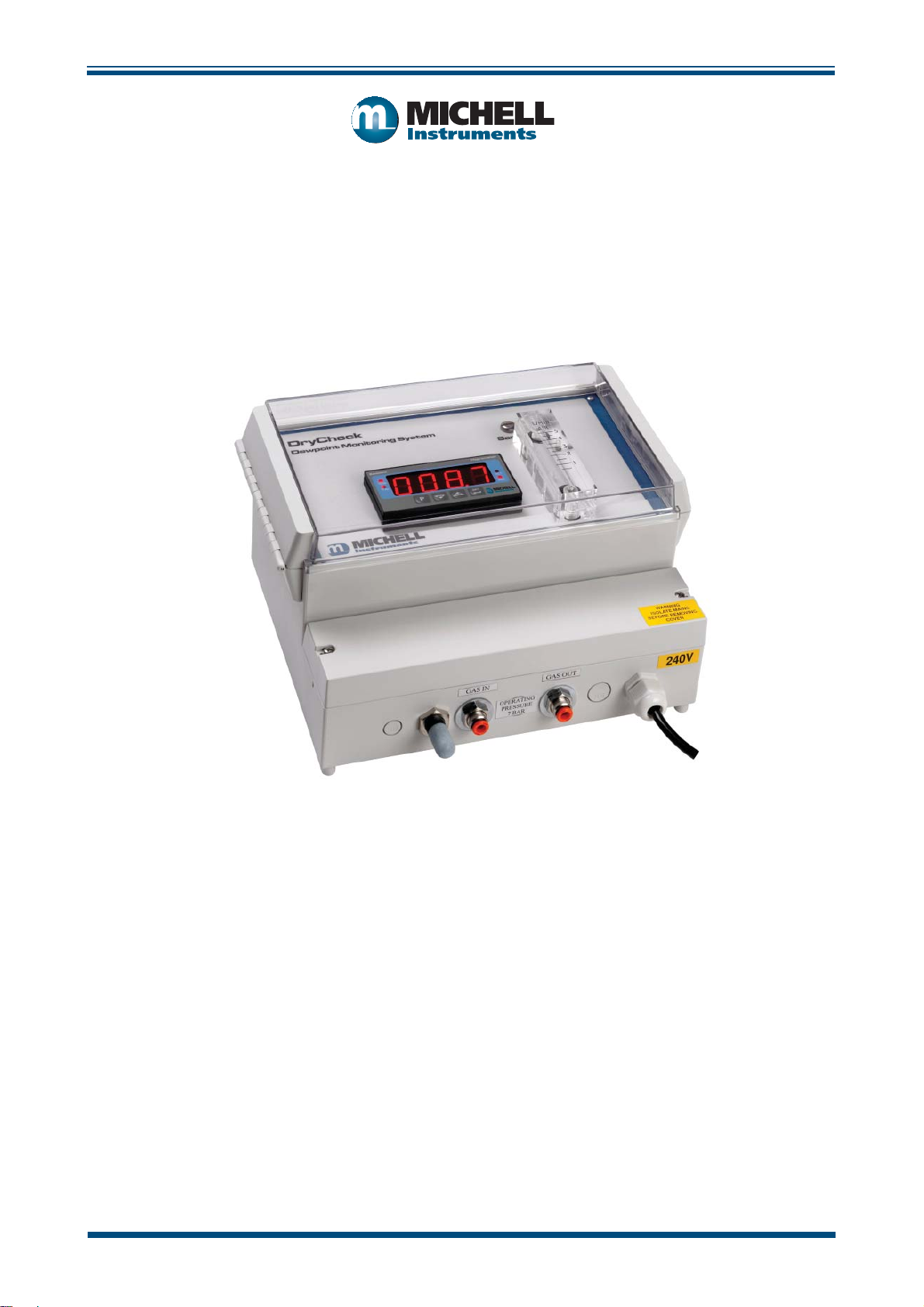
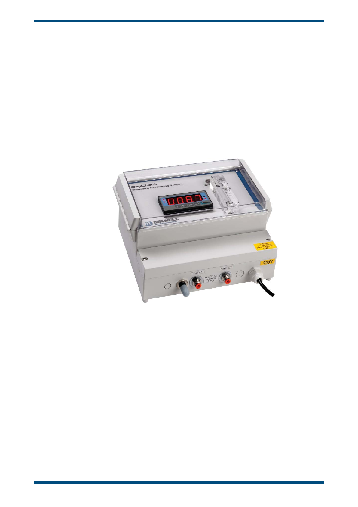
The Easidew DryCheck is an instrument designed for continuous, online measurement
of moisture content in compressed air and other gases over an operating range of over
either -100 to +20°Cdp (-148 to -4°Fdp) / -60 to +60°Cdp (-76 to 140°Fdp) / -50 to
+50°Cdp (-58 to 122°Fdp). The Easidew DryCheck is protected within an IP65-rated,
wall-mounted enclosure with a hinged lid. The lid allows access to a panel-mounted,
process indicator with a °C dew-point display.
Easidew DryCheck User’s Manual
Figure 1
Easidew DryCheck
1.2 Features
Integrated instrument and sampling system
• Simple installation
• Wide measurement range
• Dew point or moisture content
• Analog output, display and alarm
• IP65 (NEMA 4x) enclosure
viii 97108 Issue 13, July 2017
Page 9
Easidew DryCheck User’s Manual
2 INSTALLATION
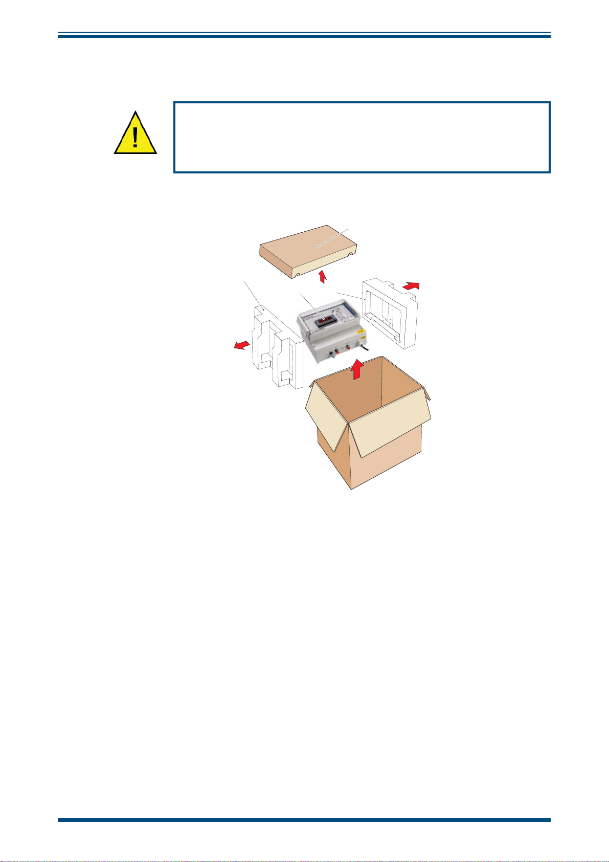
2.1 Unpacking the Instrument
It is essential that the connection of electrical and gas supplies
to this instrument be undertaken by competent personnel.
The Easidew DryCheck instrument and its accessories are packed into a box and the
method of unpacking is shown as follows:
1
INTRODUCTION
4
2
3
Figure 2
Open the box and unpack carefully (see
Unpacking Method
Figure 2)
:
1. Remove the accessories box (4).
2. Lift out the instrument (2) together with its end packing pieces (1) and
(3).
3. Remove the end packing pieces and set the instrument down at the site
of installation.
Save all the packing materials for the purpose of returning the instrument for
re-calibration or any warranty claims.
The accessories box (4) should contain the following items
:
• Traceable calibration certificate
• User manual
• Country specific power cable
On delivery please check that all the standard components shown above are present in
the packing box. Immediately report any shortages to Michell Instruments.
Michell Instruments 1
Page 10
INSTALLATION
2.2 DryCheck System Configuration
The DryCheck sampling system includes a 0.3 m particulate filter element, a monolithic
sampling block to house the transmitter, and a valve and flowmeter for setting the sample
flow. The filter element is easily replaceable to ensure that the sensor is protected. All
components are rated to 1 MPa (10 barg) and the DryCheck can be configured for
measurement of dew point at either system or atmospheric pressure.
All components are housed in a rugged IP65 (NEMA 4x) rated polycarbonate case. This
can easily be wall mounted at a convenient point close to the gas sample.
A clear cover protects the display and the sample flowmeter. Gas connection (gas in and
gas out) is provided using quick connect push fittings suitable for use with 6mm (¼”)
OD Teflon tubing. Mains power input and connection to the 4-20 mA analog output and
the two user programmable voltage free relay contacts are all easily accessible behind
the lower panel.
Easidew DryCheck User’s Manual
NOTE: The DryCheck is designed to measure dew point at standard instrument
air pressure or 7 barg.
A barometric version is available on request, please contact Michell Instruments (see
www.michell.com for contact details).
2.3 Monitor
The controls and indicators associated with the Easidew DryCheck are located on the
front panel of the monitor.
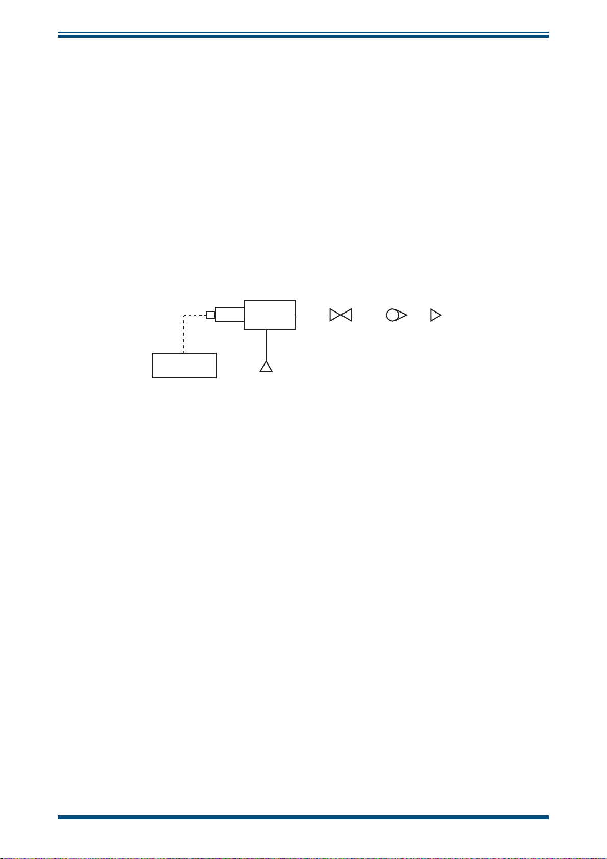
Easidew
Online
Easidew
TX Sensor
Sample
Block
Gas Inlet
Figure 3
Needle
Valve
Flowmeter
Gas Flow Diagram
Gas Outlet
Connections to the monitor and the external power supply are made to the rear panel
of the monitor and are replicated on two terminal blocks.
Figure 4
shows the layout of these controls and Tables 1 and 2 describe their respective
operational functions.
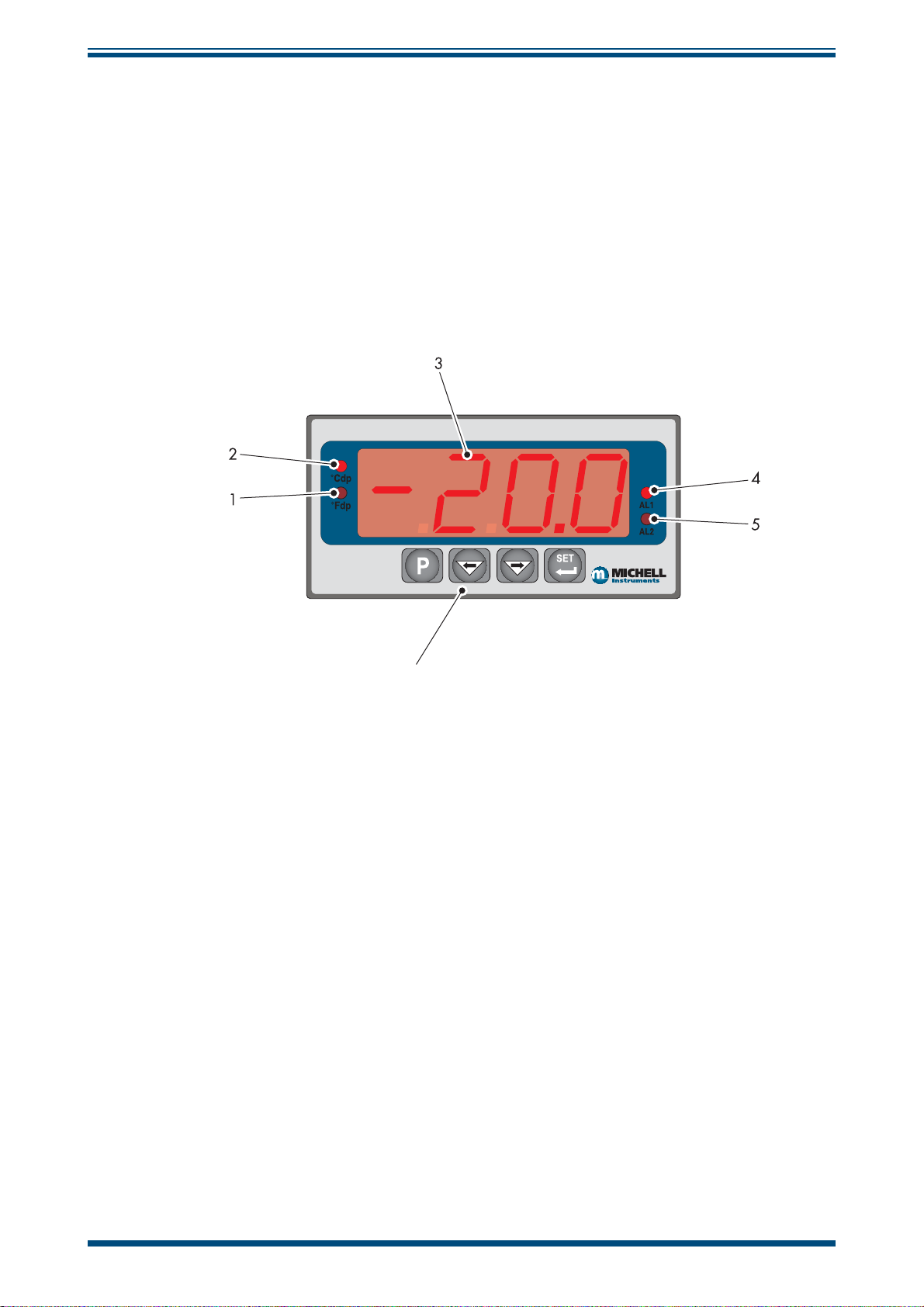
Dew-point temperature units are displayed by one of the two LEDs located to the left
of the display. On delivery, °Cdp is set-up as standard. If required, the units can be
changed to °F. The method of configuring the unit for °F is described in Section 3.4.
Optionally, the instrument can be set-up to read dew point in parts per million (ppm
range 0 to 3000 ppm
. This option requires the transmitter to be set-up for ppmV either
V
V
at the time of ordering or subsequently via Michell application software. NOTE: No
specific ppm
LED indicator is provided on the monitor; ppmV is selected if
V
neither the °Cdp nor the °Fdp temperature indicators are illuminated.
2 97108 Issue 13, July 2017
),
Page 11
Easidew DryCheck User’s Manual
Two temperature alarm indications are provided by two LEDs located on the right hand
side of the display. These are marked ALr1 (low) and ALr2 (high). Access to the alarm
relay contacts is provided on the rear panel. The connection for the ALr2 contact is
shown in Section 2.8.
NOTE: Every monitor is factory fitted with 2 alarm relays as standard. On the
DryCheck product only 1 relay (
2.4 Monitor Panel Layout
Easidew Hygrometer
INSTALLATION
ALr2) is brought to the terminal strip.
6
Figure 4
Monitor Panel Layout
Michell Instruments 3
Page 12
INSTALLATION
Item Description
°Fdp
Easidew DryCheck User’s Manual
1
2
3
4
When illuminated, this LED indicates that the displayed dew-point reading is in degrees
Fahrenheit.
NOTE: If neither the °Fdp or °Cdp LED is lit, ppm
°Cdp
When illuminated, this LED indicates that the displayed dew-point reading is in degrees
Celsius.
NOTE: if neither the °Cdp nor °Fdp LED is lit, ppm
Main dew-point temperature display
Flashes to alternately indicate ErrL (error low) and temperature reading for low
temperatures under-range (lower than -100°Cdp (-148°Fdp) or -129.9°Cdp (199.9°Fdp)
for an open loop condition).
Flashes to alternately indicate
temperature over-range.
ALr1 Output
Only available directly from the back of the Monitor panel.
ALr2
ErrH (error high) and temperature reading for high
is selected.
V
is selected.
V
When illuminated this LED indicates that the dew-point temperature programmed for
Alarm 2 has exceeded the programmed threshold. Under these conditions the alarm
relay changeover contacts associated with this alarm will change state and will remain in
this state until the temperature moves back to within the programmed operational limit.
5
Alarm 2 is usually allocated to the High Alarm setting.
These changeover relay contacts are rated at 240 V, 3 A and are connected as shown
in Section 2.8.
Section 3.4.3 details the setting up of
6
P
Table 1 Monitor Front Panel Controls and Indicators
SET
ALr2 trip points.
The four function keys are used for setting up the
monitor.
Table 2 describes the operation of the keys.
4 97108 Issue 13, July 2017
Page 13
Easidew DryCheck User’s Manual
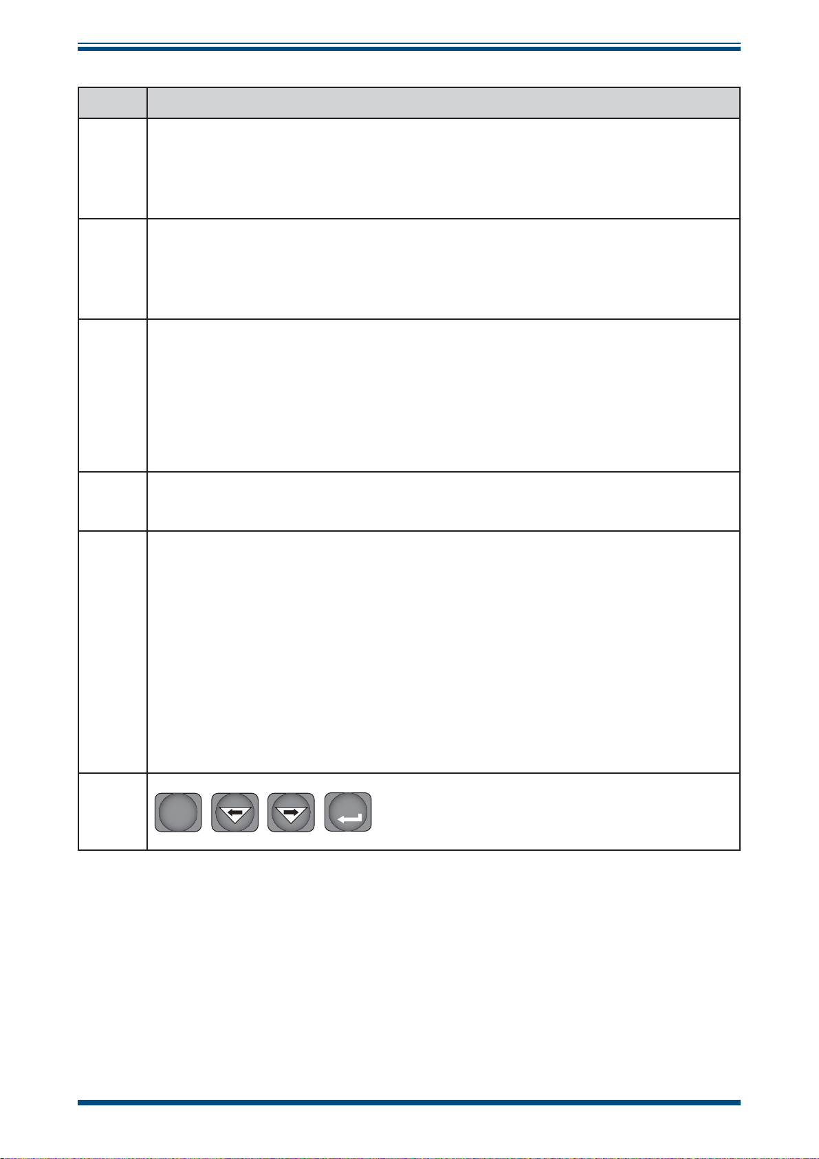
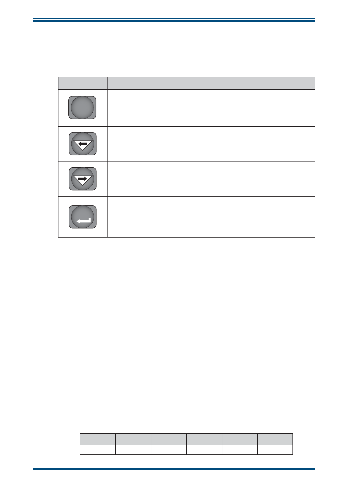
2.5 Function Keys
INSTALLATION
The function key panel is shown in
Table 2 describes the operation of the keys.
Item Description
Figure 4
P (Program) key
P
This key is used to access the programming menus and to select submenus within the list.
Left arrow (decrement) key
This key is used to access sub-menus and, within individual sub-menus,
to decrease the numeric value of the selected parameter.
Right arrow (increment) key
This key is used to access sub-menus and, within individual sub-menus,
to increase the numeric value of the selected parameter.
SET key
SET
Depending upon the context, this key is used to access the set value
of the selected process fi eld and as an Accept key for new parameter
values.
.
2.6 Mounting
The instrument is designed for wall or panel-mounting and has 3 fixing points. Mounting
fasteners are not supplied. See the System Drawing in Appendix B for wall-mount fixing
points.
2.7 Power Supply
A single-phase mains power supply of 100 to 240 V (-15% / +10%), 50/60 Hz, 6 VA is
required to power the Easidew DryCheck.
Loosen the 2 screws and remove the access cover at the lower front of the instrument
(Figure 5)
passed.
The power supply cable should then be connected to the terminal strip which is mounted
on the right hand side.
. A cable gland is provided, through which the power supply cable should be
Table 2 Function Keys
Terminals are marked:
7 8 9 101112
Earth Not Used Neutral Not used Live Not used
Michell Instruments 5
Page 14

INSTALLATION
2.8 Signal Output Connections
The Easidew DryCheck has 1 signal output Alarm 2 (ALr2) and the re-transmitted
input signal (4-20 mA or 0-20 mA current loop signal depending upon instrument
configuration).
Loosen the 2 screws and remove the access cover at the lower front of the instrument
(Figure 5)
mounted on the
Terminals are marked:
. The signal cable should then be connected to the terminal strip which is
left hand side.
Easidew DryCheck User’s Manual
For Alarm Connections
123456
Normally
Closed
Normally
Open
Figure 5
COM Not used + mA - mA
Alarm and Communications
For mA Signal
Connections
The signal outputs will be connected to external systems that
can potentially influence the operation of the process.
Alarm level signals could be at mains potential so it is essential
that, before connecting these signal lines, checks are made
to ensure that these inputs are not live and that it is safe to
handle them.
Alarm Output
Alarm 2 comprises a set of changeover contacts. Connect incoming signal lines to
terminal 3 (common), terminal 2 (normally open) and terminal 1 (normally closed).
Figure 6
electrical connections to the monitor.
shows the relevant rear panel connections. Table 3 shows a summary of all the
6 97108 Issue 13, July 2017
Page 15

Easidew DryCheck User’s Manual
INSTALLATION
Figure 6
Monitor Rear Panel Connections
Re-transmission Output
The re-transmission output is current sourcing. Connect the positive output to terminal
14 and the negative output to terminal 13. Use appropriately colored wires eg. red
(positive), black (negative).
Terminal Wire Color Signal Supply Information
1 Blue 0 V (GND)
3 Green 4-20 mA loop current Default 4-20 mA
4Red
7 User defi ned ALr2 (normally closed)
8 User defi ned ALr2 (normally open)
9 User defi ned ALr2 (common)
Transmitter loop supply
(+ve)
+24 V DC w.r.t. terminal 1
8
7
9
13 User defi ned Current loop out (-ve) Default 4-20 mA
14 User defi ned Current loop out (+ve) Default 4-20 mA
16 User defi ned ALr1 (common)
17
17 User defi ned ALr2 (normally open)
16
23 (AC Version) Blue Power in (neutral) 100 – 240 V, 50/60 Hz
24 (AC Version) Brown Power in (live) 100 – 240 V, 50/60 Hz
23 (DC Version) Black Negative (-) 0 V
24 (DC Version) Red Positive (+) 24 V
NOTE: There are no terminals in positions
5, 6, 10, 11, 12, 15, 18, 19, 20, 21 and 22
Table 3 Summary of Electrical Connections
Michell Instruments 7
Page 16

INSTALLATION
3 OPERATION
As supplied, the instrument is ready for operation and has been set-up with default
parameters. This section describes both the general operation of the instrument and
the method of setting it up and changing the default parameters should this become
necessary.
The default parameters are as follows:
• Span -100 to +20°Cdp (-148 to +68°Fdp), -60 to +60°Cdp (-76 to
140°Fdp) / -50 to +50°Cdp (-58 to 122°Fdp) or 0 to 3000 ppm
• Temperature units °Cdp
• Current loop input, 4-20 mA (7.5°C/mA or 13.5°F/mA)
• Re-transmission current loop output, 4-20 mA (7.5°C/mA or 13.5°F/mA)
• Alarm 2 set-point -40°Cdp (-40°Fdp)
Easidew DryCheck User’s Manual
V
For the supplied dew-point transmitter, the span and current loop input setting should
not be changed. The span will require changing if the instrument is to be ranged in °F,
if a different transmitter is employed, if the user chooses to re-range the transmitter or
if ppm
is selected.
V
The instrument must also have been installed as detailed in Section 2 and connected to
a sample gas supply that is representative of the process being monitored.
3.1 General Operational Information
Operation of the Easidew DryCheck is completely automatic and, once set-up, requires
little or no operator intervention.
The dew-point transmitter is designed to operate in a flowing gas stream of between 1
to 5 Nl/min (2.1 to 10.6 scfh) when mounted in a sample block, at operating pressures
up to a maximum of 10 barg (145 psig).
The sample gas is taken into the sample block via the Gas In port and, in flowing
through the sample block, comes into contact with the dew-point transmitter which,
in turn, produces a current loop output signal proportional to the measured dew-point
temperature. This output signal is converted to a dew-point temperature reading by the
monitor.
If necessary, gas flow through the sample block must be controlled outside the
instrument, typically by means of a needle valve located in the sample gas input line.
8 97108 Issue 13, July 2017
Page 17

Easidew DryCheck User’s Manual
3.2 Preparation For Operation
3.2.1 First Time Operation
To commence operation, proceed as follows:
1. Check that electrical power supply and the relevant analog and alarm
outputs are connected to external systems as required and as described
in Section 2.8.
2. Check that the gas sample flow rate through the sample block, or the
pipeline in which the transmitter is located, is within the operational
limits. (Adjust any external flow control valves, located in the gas sample
input line to the instrument to achieve required flow rate.)
3. Switch on the power supply to the instrument. The instrument display
will now come on, typically showing the default parameters and units as
detailed in
The instrument is now operational and after a few seconds, in which all the segments of
the display are tested, the monitor will display the measured dew-point temperature as
a steady reading within the range -100 to +20°Cdp (-148 to +68°Fdp), -60 to +60°Cdp
(-76 to 140°Fdp) / -50 to +50°Cdp (-58 to 122°Fdp) or 0 to 3000 ppm
how the instrument has been set-up. The default setting is °C.
Figure 7
.
OPERATION
depending upon
V
In the absence of any error indications the instrument will now be operational using the
default parameters.
Easidew Hygrometer
Figure 7
If the display is flashing, a fault condition exists. The following operational error
conditions may be encountered:
Typical Display
ErrL - If the display is alternately flashing (e.g.) ErrL and -103.3, this
indicates that the measured dew point is outside the lower operational limit
(-100°Cdp/-148°Fdp).
If the display is alternately flashing
temperature in °F), this could be an indication that the input current loop to
the monitor is open or that there may be a transmitter fault. Check that the
transmitter is wired correctly as detailed in Section 2.8.
ErrL and -129.9 (-199.9 if set-up to read
ErrH - If the display is alternately flashing (e.g.) ErrH and 021.4, this
indicates that the measured dew point is outside the upper operational
limit (+20°Cdp/+68°Fdp).
Michell Instruments 9
Page 18

OPERATION
3.3 System Alarms
3.3.1 Alarm Switching Logic (Default)
The Easidew DryCheck has one alarm output. As supplied, the default alarm set-point
and the alarm switching logic are as follows (the default temperature units are degrees
Celsius):
Easidew DryCheck User’s Manual
Alarm 2 (High Alarm) is set to switch
wetter) than its set-point value. For the default set-points therefore, the operation of
this alarm would be as follows:
Alarm 2 Temp < -40 Alarm 2 = OFF
Temp > -40 Alarm 2 = ON
Depending upon the application, if required, it is possible to reverse the switching logic
for either or both of the alarm channel outputs to provide the following alarm output
configurations:
Alarm 2 Temp < -40 Alarm 2 = ON
Temp > -40 Alarm 2 = OFF
Section 3.3.2 describes the method for reversing the default switching logic and Section
3.3.3 describes the method for setting up individual alarm set-points.
3.3.2 Reversal of Alarm Switching Logic
ON when the temperature reading is higher (gas
As described in Section 3.3.1, the switching logic for the alarm channel may, if required,
be reversed.
Starting at the default state, the method of reversing the switching logic for the alarm
is as follows:
1. Press the
2. Press the
3. Press the key three times and the display will flash between
P key once and the display will read tECH.
SET key and the display will flash between ConF and PinP.
ConF and
Alr2.
4. Press the
5. Press the key once to display a flashing 4 digit number. For the Alarm
2 default setting this will be 0000.
6. Press the key once to change the display to 0001.
7. Press the
8. Press the
SET key twice to display Alt2.
SET key to store the new value.
P key twice to return.
10 97108 Issue 13, July 2017
Page 19

Easidew DryCheck User’s Manual
OPERATION
Main
Display
P
SET
x3
SET
SET
P
x2
P
Main
Display
Figure 8
Michell Instruments 11
Change Alarm Switching Logic
Page 20

OPERATION
3.3.3 Alarm Level Set-Up
The alarm set-point levels are set-up
from the program menu as follows
(to exit to the Main Display without
saving any new settings press the
key):
Figure 9
sequence.
To set-up the alarm set-point:
shows the operational key
Easidew DryCheck User’s Manual
Main display
P
Set x2
SET
1. Press the
SET key twice.
2. Press the key to display the
flashing current Alarm 2 set-point
(-40°C in this example).
3. Use the or keys to set the
required value (-50°C in this
example).
4. Press the
SET key once to store the
new value for Alarm 2. The display
then returns to the main dew-point
temperature display.
P
P to exit
without
setting
Figure 9
Current
Value
New
Value
SET
Set-up Alarm Levels
12 97108 Issue 13, July 2017
Page 21

Easidew DryCheck User’s Manual
3.3.4 Re-Transmitted Output Current Range Set-Up
The Easidew DryCheck is provided with an
analog current loop output module which
buffers and re-transmits the current loop
input signal from the dew-point transmitter.
By default, the re-transmission output is set
as a 4-20 mA current loop (to exactly follow
the input signal, i.e. 4 mA in, 4 mA out).
For certain system processes, a 0-20 mA
current loop output may be required. The
set-up method is as follows:
OPERATION
P
SET
Figure 10
shows the operational key
sequence.
Change output from 4-20 mA to 0-20
mA
1. Press the
read
2. Press the
flash between
P key once, the display will
tECH.
SET key and the display will
ConF and PinP.
3. Press the key and the display will
flash between
4. Press the
out1 and ConF.
SET key to display oAt1.
5. Press the key once to display a
flashing 4 digit number. For the default
setting (4-20 mA) this will be 0001.
6. Press the key once to change the
display to 0000. This selects the retransmission output to be 0-20 mA.
7. Press the
SET key to accept the new
value. The output current loop is now
0-20 mA. The display will flash between
out1 and ConF.
8. Press the
main dew-point temperature display.
P key once to return to the
Figure 10
SET
Default setting
0001=4 to 20mA
New setting
0000=0 to20mA
SET
P
Main
Display
Configure Analog Output
NOTE: The transmitter current loop output signal is now scaled at 6 mA per °C
input, while the transmitter input remains scaled at 7.5°C per mA.
Michell Instruments 13
Page 22

OPERATION
Easidew DryCheck User’s Manual
3.4 Operating Temperature / ppmV Range
3.4.1 Temperature Range Default
The default temperature unit for the Easidew DryCheck is in degrees Celsius. This is
indicated by the °Cdp LED indicator. The default settings associated with this temperature
scale are as follows:
• Span -100 to +20°Cdp
• Lower and upper span limits -100 and +20 (display flashes outside this
range)
• Minimum alarm set-point -100°Cdp
• Maximum alarm set-point +20°Cdp
To range the instrument for °F, all the above parameters need
to be changed to their Fahrenheit equivalent values (-148 and
+68°F). It is not sufficient just to change the °F/°C units.
To change the range to Fahrenheit follow the procedures in Section 3.4.2.
14 97108 Issue 13, July 2017
Page 23

Easidew DryCheck User’s Manual
3.4.2 Span and Unit Settings
To change the span and unit settings,
proceed as follows.
Figure 11
operational key sequence.
1. Press the P key once, the display will
tECH.
read
shows the
OPERATION
Main Display (°C)
P
SET
x6
2. Press the
display will read
SET key six times and the
tPoL.
3. Press the key and the display will
flash with the current minimum span
limit (-100.0).
4. Use the or keys to set the
required equivalent Fahrenheit value
(-148.0) and press the
SET key.
tPoH is then displayed.
5. Press the key, the display will
flash the current maximum span
limit (020.0).
6. Use the or keys to set the
required equivalent Fahrenheit value
(068.0) and press the
SET key twice.
unit is then displayed.
7. Press the key, the display will
flash the current unit (°C).
Set Span min
Set Span max
SET
SET
x2
SET
SET
Set alarm lower range limitSet alarm upper range limit
8. Use the or keys to set the
required scale units (°F in this
example) and press the
SET key.
LoL is then displayed.
P
Main Display (°F)
9. Press the key and the display will
flash with the current alarm lower
range limit (-100.0).
Select required temp units
SET
10. Use the or keys to set the
required equivalent Fahrenheit value
(-148) and press the
SET key. uPL is
then displayed.
Figure 11
Span and Unit Settings
11. Press the key, the display will
flash the current alarm upper range
limit (020.0).
12. Use the or keys to set the required equivalent Fahrenheit value
(068.0) and press the
13. Press the
P key twice to return to the Main Display.
SET key. PUoF is then displayed.
x2
The maximum and minimum alarm level limits should now be changed to suit the new
(Fahrenheit) unit values (refer to Section 3.4.3).
Michell Instruments 15
Page 24

OPERATION
3.4.3 Alarm Set-Point Limit Configuration
The following procedure is used to set limits to
which the alarm levels can be set (usually after reconfiguring the instrument’s range for Fahrenheit
readings).
Easidew DryCheck User’s Manual
Main display
P
Figure 12
shows the operational key sequence.
1. Press the P key once, the display will read
tECH.
2. Press the
flash between
3. Press the key four times and the display
will flash between
4. Press the
SET key once and the display will
ConF and PinP.
ConF and GEnn.
SET key once, the display will read
SU-L.
5. Press the key once to display a flashing
4 digit number representing the current
minimum alarm level setting. (The default
setting for the °C range is -100.0).
6. Use the or keys to set the required new
value (e.g. -148.0).
7. Press the
The display will read
SET key to accept the new value.
SU-u.
SET
x4
SET
Set alarm setpoint lower limitSet span alarm setpoint upper limit
SET
8. Press the key once to display a flashing
4 digit number representing the current
maximum alarm level setting. (The default
setting for the °C range is 020.0)
9. Use the or keys to set the required new
value (e.g. 068.0).
10. Press the
followed by the
SET key to accept the new value,
P key to return to the Main
Display.
Figure 12
SET
P
Main display
Set-up Alarm Set-Point Limits
16 97108 Issue 13, July 2017
Page 25

Easidew DryCheck User’s Manual
3.4.4 Scale Units to ppmV Set-Up
To change the monitor to read parts per million by volume (ppmV) proceed as follows:
OPERATION
Figure 13
shows the operational key sequence.
NOTE: The dew-point transmitter must be configured to provide an output
proportional to ppmV which can be set up at the time of order or by using the
Michell application software. Contact Michell Instruments for information
(for contact details see www.michell.com).
1. Press the
2. Press the
P key once, the display will read tECH.
SET key four times and the display will read dPnt.
3. Press the key, the display will flash the current decimal point position
(0001).
4. Press the key to set 0000 on the display (no decimal point), and press
SET key twice. tPoL is then displayed.
the
5. Press the key, the display will flash the current minimum span limit
(-1000)
6. Use the or keys to set the required ppm
and press the
SET key. tPoH is then displayed.
minimum reading (0000)
V
7. Press the key, the display will flash the current maximum span limit
(0200).
8. Use the and keys to set the required ppm
and press the
SET key twice. unit is then displayed.
maximum reading (3000)
V
9. Press the key, the display will flash the current unit (°C).
10. Press the key three times to set the display reading to ‘_’ (ppm
press the
SET key. LoL is then displayed.
) and
V
11. Press the key, the display will flash the current alarm lower range limit
(-1000) (formerly -100.0 with no sign or decimal point showing).
12. Use the or keys to set the required alarm lower range limit (point
where display starts to flash) (0 or different value), and press the
SET
key. uPL is then displayed.
13. Press the key, the display will flash the current alarm upper range limit
(0200) (formerly 020.0 with no decimal point showing).
14. Use the or keys to set the required alarm upper range limit (point
where display starts to flash) (3000 or different value), and press the
PUoF is now displayed.
key.
15. Press the
P key twice and the Main Display, now reading ppm
will show.
V
SET
NOTE: Neither the °C nor the °F LED indicators on the front panel
of the monitor are now lit.
On completion of the above procedure, appropriate alarm levels (relevant to the new
scale) will need to be set-up (refer to Section 3.4.3).
ppm
V
Michell Instruments 17
Page 26

OPERATION
P
SET
Easidew DryCheck User’s Manual
Main Display, e.g. °C
x4
Set decimal point (none)
Set Span min, 0 ppm(v)
SET
SET
x2
SET
SET
x2
x3
Set Span max, 3000 ppm (v)
Select ppm(v)
SET
SET
P
Set alarm lower range limit e.g. zeroSet alarm upper range limit e.g. 3000 ppm(v)
x2
Main Display, ppm(v)
Figure 13
Set-up Monitor (to read ppmV)
3.4.5 Monitor Limits When Unit Scaled to ppmV
When unit is scaled to ppmV the display will read zero when the mA input signal is
between 3 and 4 mA.
18 97108 Issue 13, July 2017
Page 27

Easidew DryCheck User’s Manual
3.5 Digital Communication Parameters Set-Up
The default parameters for the Easidew Drycheck are as follows:
Default Address = 1, Baud rate = 9600, Parity = None, Stop bits = 1
To change these parameters, proceed as follows:
OPERATION
Figure 14
1. Press the
2. Press the
3. Press the key five times, the display will flash between
4. Press the
5. Press the key once to display a flashing 4 digit number. The default
6. Use the or keys to give the required new value (e.g. 0002). NOTE:
shows the operational key sequence.
P key once, the display will read tECH.
SET key and the display will flash between ConF and PinP.
ConF and Corn.
Set-up instrument address
SET key once to display SAdr.
setting is 0001.
The range of possible addresses is between 1 and 247. Press the
SET key to accept the new value.
Set baud rate
bAud will now be displayed. Press the key once to display a flashing 4
7.
digit number. The default setting is 0003, representing 9600 baud.
8. Use the and keys to give the required new value (the range is 0 to
4). 0 = 1200 baud, 1 = 2400 baud, 2 = 4800 baud, 3 = 9600 baud, 4 =
19200 baud. Press the
Set parity
Prty will now be displayed. Press the key once to display a flashing 4
9.
digit number. The default setting is 0000, representing no parity (none).
10. Use the or keys to give the required new value (the range is 0 to 2).
0 = none, 1 = Odd, 2 = Even. Press the
value.
Set number of stop bits
StPb will now be displayed. Press the key once to display a flashing 4
11.
digit number. The default setting is 0000, representing 1 stop bit.
12. Use the or keys to give the required new value (the range is 0 - 1)
0 = 1 stop bit, 1= 2 stop bits.
13. Press the
return to the Main Display.
SET key to accept the selected value, followed by the P key to
SET key to accept the selected value.
SET key to accept the selected
Michell Instruments 19
Page 28

OPERATION
Easidew DryCheck User’s Manual
Main display
P
Set Parity
SET
SET
SET
x 5
Range between
0001 and 0247
Set Address
Set baud
SET
SET
P
Main Display (°F)
0000 = None
0001 = Odd
0002 = Even
Set number of
stop bits
0000 = 1 stop bit
0001 = 2 stop bits
SET
Figure 14
0=1200,
1=2400
2=4800,
3= 9600
4=19200
Set-up Data Communications Parameters
20 97108 Issue 13, July 2017
Page 29

Easidew DryCheck User’s Manual
OPERATION
3.6 Monitor – Reading the Displayed Value Using Modbus RTU Over RS232
It is possible to communicate with the online monitor using Modbus RTU over RS232.
The monitor has a three pin serial port connection on the back – the required cable can
be supplied by Michell.
To read the value displayed on the monitor a byte array must be created, containing
the following bytes:
Instrument
Address
Command
Reg
Address
High
Reg
Address
Low
Number
of Reg
High
Number
of Reg
Low
LRC CRC
0x01 0x04 0x00 0x00 0x00 0x01 0x31 0xCA
Send this to the instrument with the correct delays between characters:
Baud Rate (bps) Min Delay (ms) Max Delay (ms)
1200 9.17 13.76
2400 4.59 6.88
4800 2.30 3.44
9600 1.15 1.72
19200 0.57 0.86
After a few seconds the instrument will send back the following response:
Instrument
Address
Command
Number of
bytes
Display
High
Display
Low
LRC CRC
0x01 0x03 0x02 0x00 0x67 (Varies) (Varies)
Data MSB * 256 + Data LSB = 0 *256 + 103 = 103
This code, written in c, can be used to convert the 103 into a real dew-point value or
10.3:
float ConvertToReal(int Value) //convert dew-point value to real dew-point result
{float result; //declaration
if (Value > 32767) Value=(Value-65536); //convert to negative number
result = (float)(Value/10.0); //divide number by 10 to convert to float
return result; //return real value}
Michell Instruments 21
Page 30

OPERATION
4 GOOD MEASUREMENT PRACTICE
The Easidew DryCheck is designed to operate in a flowing gas stream and is suitable for
the measurement of the moisture content of a wide variety of gases. In general, if the
gas (in conjunction with water vapor) is not corrosive to ceramics or base metals then
it will be suitable for measurement by the Easidew DryCheck.
The system is designed for operation with sample gas flow rates of 1 to 5 Nl/min (2.1 to
10.6 scfh) (sample block). Ideally, the flow rate should be set-up between 4 and 6 Nl/
min. Flow regulation is provided within the Easidew DryCheck system. Always use high
quality valve gear, coupling connections and pipework.
The system will operate successfully at flow rates within its operational range and it is
important to ensure that the flow rate through the sample block is high enough to avoid
long time lags in response to humidity changes at the sample source.
Avoid pressure gradients in the system by placing excessive flow restriction on the
output side of the sample block. In applications where the test gas has a very high
flow rate, an instrument by-pass arrangement is preferable to flow restriction after the
transmitter.
Easidew DryCheck User’s Manual
Flow Rates
Theoretically flow rate has no direct effect on the measured moisture content, but in
practice it can have unanticipated effects on response speed and accuracy.
An inadequate flow rate can:
• Accentuate adsorption and desorption effects on the gas passing
through the sampling system.
• Allow pockets of wet gas to remain undisturbed in a complex sampling
system, which will then gradually be released into the sample flow.
• Increase the chance of contamination from back diffusion: ambient air
that is wetter than the sample can flow from the exhaust back into the
system. A longer exhaust (sometimes called a pigtail) can also help
alleviate this problem.
• Slow the response of the sensor to changes in moisture content.
An excessively high flow rate can:
• Introduce back pressure, causing slower response times and
unpredictable effects on equipment such as humidity generators.
Factory Flow Rate Setting
Internally the gas enters a sample block at which point an adjustable flow valve is
located. This valve is factory set to output 2.5 l/min flow at 7 barg.
22 97108 Issue 13, July 2017
Page 31

Easidew DryCheck User’s Manual
5 MAINTENANCE
5.1 General Maintenance Guidelines
Routine maintenance of the Easidew DryCheck is confined to filter element replacement
and regular recalibration of the dew-point transmitter.
5.2 Calibration
Routine maintenance of the transmitter is confined to regular re-calibration by exposure
of the transmitter to sample gases of known moisture content to ensure that the stated
accuracy is maintained. Calibration services traceable to the UK National Physical
Laboratory (NPL) and the US National Institute of Standards and Technology (NIST) are
provided by Michell Instruments.
Michell Instruments offers a variety of re-calibration and exchange sensor schemes to
suit specific needs. A Michell representative can provide detailed, custom advice (for
Michell Instruments’ contact information go to www.michell.com).
GOOD MEASUREMENT PRACTICE
5.3 Transmitter Maintenance
To replace the transmitter proceed as follows:
Always de-pressurize the system and disconnect any electronic
supplies before commencing maintenance.
1. Open the transparent front cover.
2. Remove the four screws securing the aluminum front panel.
3. Carefully lift the front panel to expose the transmitter.
4. Remove the electrical mini DIN connector from the transmitter by loosening
the connector-securing screw and pulling it away from the transmitter.
5. Unscrew the transmitter from the block using a 27AF spanner/wrench.
6. Fit a new transmitter and fully tighten to a minimum torque of 30.5Nm.
7. Repeat the above instructions in reverse order.
h
Mini DIN
Connector
h
Transmitter
Figure 15
Michell Instruments 23
Sensor Removal
Page 32

MAINTENANCE
5.4 Inspection/Cleaning
The composition of the gas determines the frequency of the filter element replacement,
i.e. liquid and particulate contaminates, corrosive elements, etc.
A disposable filter element continues to filter at its original efficiency as long as it is
kept in service. The life of the element is determined by the increase in flow resistance
caused by trapped solids in the element. The element should be changed when the flow
falls below an acceptable level, or the pressure drop becomes too high. In any case the
element should be replaced before the pressure drop across it reaches 0.7 barg (10.2
psig).
To replace a particulate filter element (Michell part SSF-PF-10PK (pack of 10)), proceed
as follows:
Always de-pressurize the system and disconnect any electronic
Easidew DryCheck User’s Manual
supplies before commencing maintenance.
1. Unscrew the stainless steel cap and withdraw it from the block.
2. The filter is a push-fit onto a mounting boss. To remove, pull apart from
the cap.
3. Refit a new element. NOTE: Do not touch the element with bare
fingers.
h
h
Filter
Element
Figure 16
24 97108 Issue 13, July 2017
Inspection/Cleaning
Page 33

Easidew DryCheck User’s Manual
5.5 Fault Conditions
MAINTENANCE
Message
Displayed
ErrL
Sbr
ErrH
outR
rurC
Cause Action
Check power supply to transmitter. Check
Sensor failure
Instrument failure
Sensor failure or break in
sensor connection
Gas is wetter than +20°Cdp Check gas source supply.
Sensor contaminated Replace/re-calibrate transmitter.
Input out of range
Reverse input connection
transmitter cable for continuity/damage.
Rectify/replace cable.
Refer to Michell or local representative for
repair.
Check transmitter cable for continuity/
damage.
Rectify/replace cable.
Check gas source supply.
Re-calibrate/replace transmitter.
Swap input connections from the
transmitter to the monitor.
Michell Instruments 25
Page 34

APPENDIX A
Easidew DryCheck User’s Manual
Appendix A
Technical Specifications
26 97108 Issue 13, July 2017
Page 35

Easidew DryCheck User’s Manual
APPENDIX A
Appendix A Technical Specifications
-100 to +20°Cdp
Electrical Specifi cations
Power Supply 85 to 265 V AC, 50/60 Hz
Operating Specifi cations
Operating Temperature -5 to +50°C (+23 to +122°F)
Storage Temperature -40 to +75°C (-40 to +167°F)
-100 to +20°Cdp (-148 to +68°F)
Measurement Range
Accuracy ±2°Cdp
Output 4-20 mA maximum load resistance 500
Alarm 2 volt free contacts 240 V, 3A
Sample Flow Rate 1 to 5 Nl/min (2.1 to 10.6 scfh)
Gas Pressure 1 MPa (10 barg/145 psig) max (high pressure option available)
Mechanical Specifi cations
User Interface Front panel confi guration of alarm points
Display 20mm (¾“) red LED
Ingress Protection IP65 (NEMA 4x)
Mains Cable 2m cable supplied
Filtration 99.5% removal of 0.3m
Gas Connection Quick connect fi ttings for 6mm (¼”) OD Tefl on pipe
3000 ppm
specifi ed at time of order)
(ppmV output or non-standard dew-point range must be
V
-60 to +60°Cdp / -50 to +50°Cdp
Electrical Specifi cations
Power Supply 85 to 265 V AC, 50/60 Hz
Operating Specifi cations
Operating Temperature -5 to +50°C (+23 to +122°F)
Storage Temperature -40 to +75°C (-40 to +167°F)
Measurement Range
Accuracy ±2°Cdp
Output 4-20 mA maximum load resistance 500
Alarm 2 volt free contacts 240 V, 3A
Sample Flow Rate 1 to 5 Nl/min (2.1 to 10.6 scfh)
Gas Pressure 1 MPa (10 barg/145 psig) max (high pressure option available)
Mechanical Specifi cations
User Interface Front panel confi guration of alarm points
Display 20mm (¾“) red LED
Ingress Protection IP65 (NEMA 4x)
Mains Cable 2m cable supplied
Filtration 99.5% removal of 0.3m
Gas Connection Quick connect fi ttings for 6mm (¼”) OD Tefl on pipe
-60 to +60°Cdp (-76 to 140°Fdp) / -50 to +50°Cdp (-58 to +122°Fdp)
Non-standard available on request
Michell Instruments 27
Page 36

APPENDIX B
Easidew DryCheck User’s Manual
Appendix B
System Drawing
28 97108 Issue 13, July 2017
Page 37

Easidew DryCheck User’s Manual
Appendix B System Drawing
APPENDIX B
Figure 17
Michell Instruments 29
System Drawings
Page 38

APPENDIX C
Easidew DryCheck User’s Manual
Appendix C
Quality, Recycling
& Warranty
Information
30 97108 Issue 13, July 2017
Page 39

Easidew DryCheck User’s Manual
APPENDIX C
Appendix C Quality, Recycling & Warranty Information
Michell Instruments is dedicated to complying to all relevant legislation and directives. Full information
can be found on our website at:
www.michell.com/compliance
This page contains information on the following directives:
• ATEX Directive
• Calibration Facilities
• Conflict Minerals
• FCC Statement
• Manufacturing Quality
• Modern Slavery Statement
• Pressure Equipment Directive
• REACH
• RoHS2
• WEEE2
• Recycling Policy
• Warranty and Returns
This information is also available in PDF format.
Michell Instruments 31
Page 40

APPENDIX D
Easidew DryCheck User’s Manual
Appendix D
Return Document
&
Decontamination Declaration
32 97108 Issue 13, July 2017
Page 41

Easidew DryCheck User’s Manual
Appendix D Return Document & Decontamination Declaration
'HFRQWDPLQDWLRQ&HUWL¿FDWH
IMPORTANT NOTE: Please complete this form prior to this instrument, or any components, leaving your
site and being returned to us, or, where applicable, prior to any work being carried out by a Michell
engineer at your site.
Instrument Serial Number
Warranty Repair? YES NO Original PO #
Company Name Contact Name
Address
Telephone # E-mail address
Reason for Return /Description of Fault:
APPENDIX D
Has this equipment been exposed (internally or externally) to any of the following?
Please circle (YES/NO) as applicable and provide details below
Biohazards YES NO
Biological agents YES NO
Hazardous chemicals YES NO
Radioactive substances YES NO
Other hazards YES NO
Please provide details of any hazardous materials used with this equipment as indicated above (use continuation sheet
if necessary)
Your method of cleaning/decontamination
Has the equipment been cleaned and decontaminated? YES NOT NECESSARY
Michell Instruments will not accept instruments that have been exposed to toxins, radio-activity or bio-hazardous
PDWHULDOV)RUPRVWDSSOLFDWLRQVLQYROYLQJVROYHQWVDFLGLF EDVLFÀDPPDEOHRUWR[LFJDVHVDVLPSOHSXUJHZLWK GU\
JDVGHZSRLQW&RYHUKRXUVVKRXOGEHVXI¿FLHQWWRGHFRQWDPLQDWHWKHXQLWSULRUWRUHWXUQ
Work will not be carried out on any unit that does not have a completed decontamination declaration.
Decontamination Declaration
I declare that the information above is true and complete to the best of my knowledge, and it is safe for Michell
personnel to service or repair the returned instrument.
Name (Print) Position
Signature Date
F0121, Issue 2, December 2011
Michell Instruments 33
Page 42

Page 43

http://www.michell.com
 Loading...