

Page 1
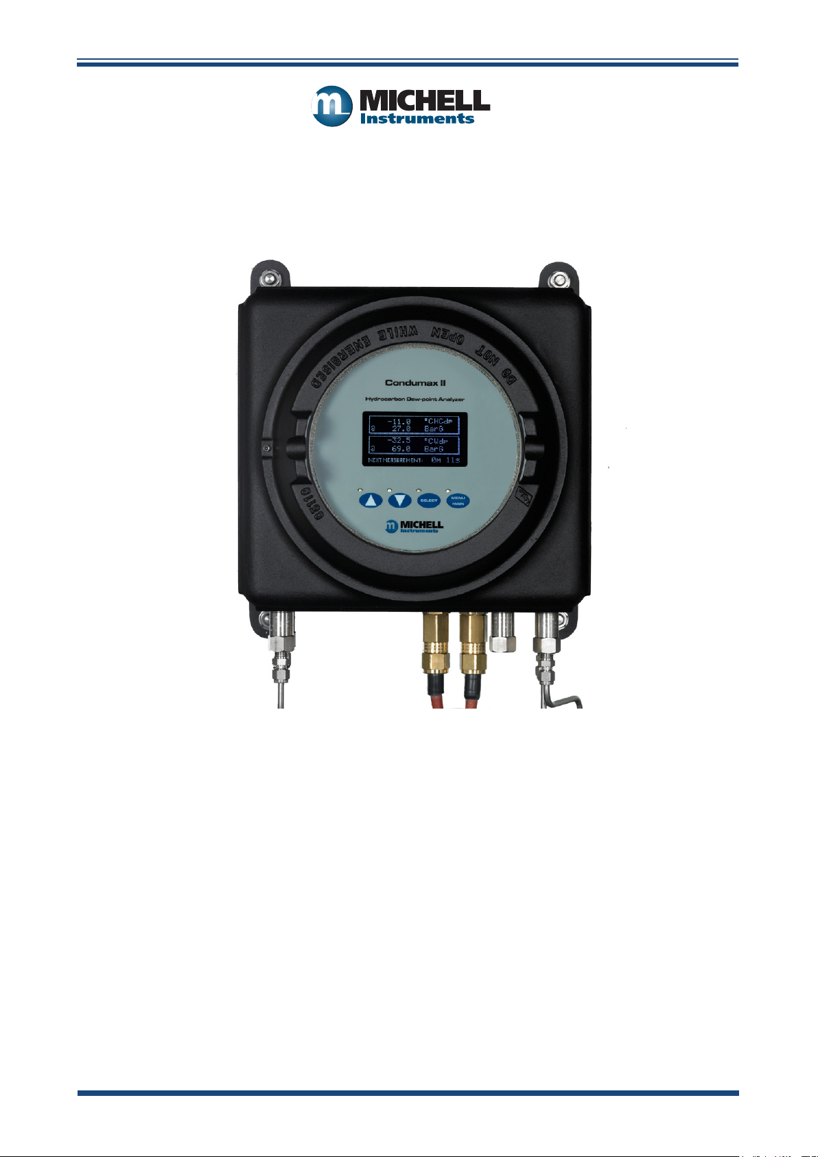
Condumax II
Hydrocarbon Dew-Point Analyzer
User’s Manual
97081 Issue 29.1
July 2019
Page 2
Please ll out the form(s) below for each instrument that has been purchased.
Use this information when contacting Michell Instruments for service purposes.
Analyzer
Code
Serial Number
Invoice Date
Location of Instrument
Tag No
Analyzer
Code
Serial Number
Invoice Date
Location of Instrument
Tag No
Analyzer
Code
Serial Number
Invoice Date
Location of Instrument
Tag No
Page 3
Condumax II
For Michell Instruments' contact information please go to
www.michell.com
© 2019 Michell Instruments
This document is the property of Michell Instruments Ltd. and may not be copied or
otherwise reproduced, communicated in any way to third parties, nor stored in any Data
Processing System without the express written authorization of Michell Instruments Ltd.
Page 4

Condumax II User’s Manual
Contents
Safety ...............................................................................................................................vii
Electrical Safety .................................................................................................................vii
Pressure Safety .................................................................................................................vii
Toxic Materials ...................................................................................................................vii
Repair and Maintenance .....................................................................................................vii
Calibration (factory validation) ...........................................................................................vii
Safety Conformity ..............................................................................................................vii
Abbreviations .................................................................................................................... viii
Warnings .......................................................................................................................... viii
1 INTRODUCTION ................................................................................................1
1.1 General ..................................................................................................................1
1.2 System Description ..................................................................................................1
1.2.1 Sample Gas Path ........................................................................................... 1
1.2.2 Operating Overview....................................................................................... 3
1.2.3 Condumax II User Display and Interface ......................................................... 3
1.2.4 Calibration .................................................................................................... 3
1.3 Condumax II Analyzer Storage Instructions ...............................................................4
2 INSTALLATION ..................................................................................................5
2.1 Electrical Safety ...................................................................................................... 5
2.1.1 Equipment Ratings and Installation Details ...................................................... 5
2.2 Hazardous Area Safety ............................................................................................8
2.3 Pressure Safety ....................................................................................................... 9
2.4 Lifting and Handling ................................................................................................ 9
2.5 Measurement System ............................................................................................ 10
2.5.1 Gas Connections, Sample Extraction & Conditioning ...................................... 11
2.5.2 Power Connection ...................................................................................... 15
2.5.3 Analog and Digital Communications ............................................................. 16
2.6 Condumax II Start-Up Purge Procedure .................................................................. 17
2.7 Sample Gas Flows ................................................................................................. 18
2.8 Sample Flow Alarms .............................................................................................. 19
3 OPERATION ....................................................................................................20
3.1 Timing Synchronization.......................................................................................... 20
3.2 Recovery Phase ....................................................................................................20
3.3 Measurement Phase .............................................................................................. 20
3.3.1 Water Dew-Point Measurement .................................................................... 21
3.3.2 Signal Changes and Trip Point ...................................................................... 21
3.3.3 Sensitivity Calibration .................................................................................. 22
3.3.4 Adjustment of Measurement Sensitivity to User Defined Reference ................. 23
3.4 User Interface ....................................................................................................... 24
3.4.1 Interface Controls ...................................................................................... 24
3.4.2 ‘Up/Down Arrow’ Buttons ............................................................................. 24
3.4.3 ‘SELECT’ Button ......................................................................................... 25
3.4.4 ‘MENU/MAIN’ Button ................................................................................... 25
3.5 Menu Structure ..................................................................................................... 26
3.6 Main Page ............................................................................................................ 27
3.7 Menu Page ........................................................................................................... 27
3.8 Status Pages ......................................................................................................... 28
3.8.1 Status Page 1 ............................................................................................. 28
3.8.2 Status Page 2 ............................................................................................. 29
3.9 Logging Menu Page ............................................................................................... 30
3.9.1 Logged Data Page ....................................................................................... 30
3.9.2 Statistics .................................................................................................... 31
3.9.3 Viewing Historical System Faults ................................................................... 31
iv 97081 Issue 29.1, July 2019
Page 5

Condumax II User’s Manual
3.10 Adjusting and Viewing System Variables .................................................................32
3.10.1 Enter Password ........................................................................................... 32
3.10.2 Variable Pages ............................................................................................ 32
3.10.3 Variables Page 1 ......................................................................................... 33
3.10.4 Variables Page 2 ......................................................................................... 33
3.10.5 Variables Page 3 ......................................................................................... 33
3.10.6 Variables Page 4 ......................................................................................... 34
3.10.7 Variables Page 5 ......................................................................................... 34
3.11 Sensitivity Calibration ............................................................................................ 35
3.11.1 Executing the Sensitivity Calibration ............................................................. 35
3.11.2 Viewing the Calibration Data ........................................................................ 35
3.12 Water Dew-Point Sensor Information ...................................................................... 36
3.13 Contact/About Information .................................................................................... 36
4 MAINTENANCE ................................................................................................37
4.1 Calibration ............................................................................................................ 37
4.2 Enclosure Cover and User Interface ........................................................................ 38
4.3 Inspection/Cleaning of Hydrocarbon Sensor Cell Optical Surface ............................... 39
4.4 Replacement of the Hydrocarbon Sensor Cell Assembly ........................................... 40
4.5 Replacement of the Water Dew-Point Sensor ........................................................... 41
4.6 Troubleshooting .................................................................................................... 42
4.6.1 Error Messages ........................................................................................... 42
4.6.2 Logged Error Codes ..................................................................................... 43
4.6.3 mA1 Output Analyzer Fault Alarm ................................................................. 44
4.6.4 Heat-Pump Depression ................................................................................ 45
Figures
Figure 1 Power Connection Connector ........................................................................... 5
Figure 2 Earthing Stud And Nut Washer Assembly .......................................................... 6
Figure 3 Condumax Dimensions .................................................................................. 10
Figure 4 Flow Schematic ............................................................................................. 11
Figure 5 Typical Phase Envelope for Northern Europe Natural Gas .................................. 14
Figure 6 Wiring Hook-Up Diagram ............................................................................... 15
Figure 7 Minimum Requirements for Start-Up Purging ................................................... 18
Figure 8 Sensitivity Calibration Plot (Example) .............................................................. 23
Figure 9 User Interface ............................................................................................... 24
Figure 10 ‘UP/DOWN ARROW’ Buttons........................................................................... 24
Figure 11 ‘SELECT’ Button ............................................................................................ 25
Figure 12 ‘MENU/MAIN’ Button ..................................................................................... 25
Figure 13 Menu Structure ............................................................................................. 26
Figure 14 MAIN Page With Wdp Sensor Fitted ................................................................ 27
Figure 15 MAIN Page Without Wdp Sensor Fitted ........................................................... 27
Figure 16 MENU Page ................................................................................................... 27
Figure 17 STATUS Page 1 ............................................................................................. 28
Figure 18 STATUS Page 2 ............................................................................................. 29
Figure 19 LOGGED DATA Page ...................................................................................... 30
Figure 20 STATISTICS Page .......................................................................................... 31
Figure 21 Logged Error Codes ....................................................................................... 31
Figure 22 Password Page .............................................................................................. 32
Figure 23 Variables Page .............................................................................................. 32
Figure 24 Sensitivity Calibration Page ............................................................................ 35
Figure 25 Sensitivity Calibration Data Page .................................................................... 35
Figure 26 Water Dew-Point Sensor Information Page ...................................................... 36
Figure 27 Contact/About Information Page .................................................................... 36
Figure 28 Error Messages ............................................................................................. 42
Figure 29 Logged Error Codes ....................................................................................... 43
Figure 30 Reading Holding Registers State Diagram ........................................................ 68
Figure 31 Write Single Register State Diagram ............................................................... 70
Michell Instruments v
Page 6

Condumax II User’s Manual
Appendices
Appendix A Technical Specications ..............................................................................47
A.1 Mounting Drawing ....................................................................... 48
A.2 Flow Diagram ............................................................................. 49
A.3 Wiring Hook-Up Diagram ............................................................. 50
Appendix B Modbus RTU Communications ....................................................................52
B.1 Introduction ...............................................................................52
B.2 Modbus RTU Basics ..................................................................... 52
B.3 Modbus RTU Basics ..................................................................... 52
B.4 Register Map .............................................................................. 53
Appendix C Software ................................................................................................... 57
C.1 System Requirements .................................................................. 57
Appendix D Variables Pages ......................................................................................... 59
D.1 Variables Page 1 .........................................................................59
D.2 Variables Page 2 .........................................................................61
D.3 Variables Page 3 .........................................................................62
D.4 Variables Page 4 .........................................................................63
D.5 Variables Page 5 .........................................................................65
Appendix E Modbus RTU Details ..................................................................................67
E.1 Message Framing ........................................................................ 67
E.2 Implemented Functions ...............................................................68
E.3 Exceptions .................................................................................. 72
Appendix F Number Formats ....................................................................................... 74
Appendix G Hazardous Area Certication ......................................................................80
G.1 Product Standards ....................................................................... 80
G.2 Product Certication ....................................................................80
G.3 Global Certicates/Approvals ........................................................ 80
G.4 Special Conditions of Use ............................................................. 81
G.5 Maintenance and Installation ....................................................... 81
Appendix H Quality, Recycling, Compliance & Warranty Information ................................ 83
Appendix I Analyzer Return Document & Decontamination Declaration .......................... 85
vi 97081 Issue 29.1, July 2019
Page 7
Condumax II User’s Manual
!
Safety
This manual contains all the required information to install, operate and maintain the Condumax II.
Prior to installation and use of this instrument, this entire manual should be read and understood.
Installation and operation of this product should be carried out by suitably competent personnel only.
The operation of this product must be in accordance with the terms of this manual and associated
safety certificates. Incorrect installation and use of this product for other than its intended purpose
will render all warranties void.
This product is intended for use in a Hazardous Area and is awarded an ATEX, IECEx and CSA
Certificate. The relevant certificates should be fully examined prior to installation or use of this
product.
Where this hazard warning symbol appears in the following
sections, it is used to indicate areas where potentially hazardous
operations need to be carried out and where particular attention to
personal and personnel safety must be observed.
Electrical Safety
The instrument is designed to be completely safe when used with options and accessories supplied
by the manufacturer for use with the instrument. The input power supply voltage limits are 90 to
260 V AC, 47/63 Hz.
Pressure Safety
DO NOT permit pressures greater than the safe working pressure to be applied directly to the
instrument. Refer to the Technical Specifications in Appendix A.
Toxic Materials
The use of hazardous materials in the construction of this instrument has been minimized. During
normal operation it is not possible for the user to come into contact with any hazardous substance
which might be employed in the construction of the instrument. Care should, however, be exercised
during maintenance and the disposal of certain parts.
Repair and Maintenance
The instrument must only be maintained either by the manufacturer or an accredited service agent.
Refer to www.michell.com for details of Michell Instruments’ worldwide offices contact information.
Calibration (factory validation)
Prior to shipment, both the hydrocarbon dew-point cell and the water dew-point cell undergo
stringent factory calibration to internationally traceable standards - NPL (UK) and NIST (USA). Due
to the inherent stability of the instruments, only periodic calibration maintenance is required under
normal operating conditions. Refer to Section 1.2.4 and 4.1 for more information.
Safety Conformity
This product meets the essential protection requirements of the relevant EU directives. Further
details of applied standards may be found in the product specification.
Michell Instruments vii
Page 8

Abbreviations
The following abbreviations are used in this manual:
AC alternating current
atm pressure unit (atmosphere)
barg pressure unit (=100 kP or 0.987 atm) gauge
°C degrees Celsius
°F degrees Fahrenheit
DC direct current
dp dew point
EU European Union
3
g/m
HCdp hydrocarbon dew point
IEC International Electrotechnical Commission
kg kilogram
lb pound
lbs/mmscf pounds of water per million standard cubic feet of gas
m meter(s)
mA milliampere
max maximum
3
mg/m
mm millimeters
mV millivolts
Nl/min normal liters per minute
Nm3/hr normal cubic meters per hour
% percentage
ppmV parts per million by volume
psig pounds per square inch
RS232 serial data transmission standard
RS485 serial data transmission standard
RTU Remote Terminal Unit
scfh standard cubic feet per hour
temp temperature
V Volts
W Watts
Wdp water dew point
Ω Ohms
“ inch(es)
Condumax II User’s Manual
grams per cubic meter
milligrams per cubic meter
Warnings
The following general warnings listed below are applicable to this instrument. They are
repeated in the text in the appropriate locations.
Where this hazard warning symbol appears in the following
sections it is used to indicate areas where potentially
hazardous operations need to be carried out.
Where this symbol appears in the following sections it is
used to indicate areas of potential risk of electric shock.
viii 97081 Issue 29.1, July 2019
Page 9

Condumax II User’s Manual
1 INTRODUCTION
1.1 General
The Condumax II is designed for continuous, automatic measurement of the hydrocarbon
dew point and water dew point of processed natural gas. It is the result of more than 30
years' experience in the supply of analyzers to the worldwide oil, gas and petrochemical
industry.
The system consists of a hydrocarbon dew-point measurement sensor cell and control
electronics housed in an Exd enclosure. An optional water dew-point measurement
sensor can be accommodated, either at the time of build or as a retro-t option. A
sample gas handling panel to prepare the gas sample prior to entry into the Condumax
II can also be supplied. The analyzer is designed to be positioned close to the process
sample point and is ATEX Directive, IECEx or cCSAus compliant for use in a Zone 1 or
2 Hazardous Area and Class I, Div 1 Hazardous Location. See marking label located on
right hand side of analyzer to identify approvals.
INTRODUCTION
The unique measurement principle of the Condumax II involves detecting the formation
of hydrocarbon condensate through a highly sensitive secondary optical eect.
A reduction in scattered light intensity is observed when a well-collimated incident
light beam is reected from a shallow, abraded, conical depression by hydrocarbon
condensate forming on the measurement surface. This measurement surface is referred
to as the Optical Surface (see Section 3.8.1). The cooling of the measurement surface
is achieved using a Peltier eect (thermo-electric) heat pump. The use of this device
enables measurements to be made down to more than 50°C below the operating
temperature of the analyzer.
The Condumax II operates on a periodic measurement cycle basis. The sample ow is
continuous until, at the start of a measuring cycle, the ow is interrupted, trapping a
sample of gas within the sensor cell until the dew point is measured.
This technique of analyzing a xed volume sample successfully de-couples thermal
mass transfer and ow eects on the observed dew point ensuring that repeatable
measurements are made to a constant level of measurement sensitivity.
1.2 System Description
The requirements for operation are a 90 to 260 V AC, 47/63 Hz power supply of 125 W
and eld communications; Modbus RTU and/or 4-20 mA. Refer to the ‘Wiring Hook-Up
Diagram’ in Appendix A.3.
1.2.1 Sample Gas Path
The Condumax II measurement system must be supplied with gas at the required
pressure via a sample gas handling panel. The hydrocarbon dew-point stream is always
included as part of the system and, as an additional option, the water dew-point stream
can be tted. Sample gas entry and exit ports pass the gas through ame arrestors
which provide the explosion proof protection.
Michell Instruments 1
Page 10

INTRODUCTION
The measurement system components are housed within a cast aluminum EExd rated
enclosure. The enclosure has a screw cover incorporating a sealed window. It is
chromate primed, polyester coated in black, and provides environmental protection to
IP66/NEMA 4. An enclosure breather is tted in the form of an additional ame arrestor.
It is important that no pipe connection is made to this breather and that no restriction
is allowed to occur.
All sample wetted metallic parts are manufactured in AISI 316L stainless steel with
Viton soft parts that comply with the NACE standard MR-01-75 (latest edition). Tube
ttings are twin ferrule compression type. All electrical and gas connections are made
through the base of the enclosure. Refer to the Mounting Drawing in Appendix A.1.
The hydrocarbon dew-point ow components are as follows (refer to the ‘Flow Diagram’
in Appendix A.2):
• Flow Switch 1
Provides indication that a ow is present throughout the hydrocarbon
dew-point measurement stream.
Condumax II User’s Manual
• Hydrocarbon Dew-point Sensor Cell
Provides the measurement of hydrocarbon dew point within the sample
gas.
• Pressure Transmitter 1
Provides the measurement of the sample gas pressure within the
hydrocarbon dew-point measurement cell.
• Solenoid Valve
Enables sample gas shut o to provide xed volume measurement.
The water dew-point ow components are as follows:
• Flow Switch 2
Provides indication that a ow is present throughout the water dew-point
measurement stream.
• Pressure Transmitter 2
Provides the measurement of the sample gas pressure within the water
dew-point measurement cell.
2 97081 Issue 29.1, July 2019
Page 11

Condumax II User’s Manual
1.2.2 Operating Overview
At the beginning of a measurement cycle, the sample solenoid valve is closed to trap a
gas sample in the hydrocarbon sensor cell for analysis and the controlled cooling of the
optical surface commences. When the scattered light intensity, measured by the optical
measurement system, reaches a user-set trip point, the temperature of the optical
surface is recorded as the hydrocarbon dew point. After this, the sample gas ow is
restored and the optical surface is heated to the temperature set-point. The heating of
the optical surface to an elevated temperature ensures that any hydrocarbon residue is
released from the optical surface before the next measurement cycle.
This measurement process is repeated cyclically at intervals determined by the control
system and pre-set by the operator. The minimum cycle time is 10 minutes and under
ideal conditions, when the condensate formed is suciently volatile to evaporate the
residue, the recovery phase will be approximately 8 minutes. However, in applications
where relatively high hydrocarbon dew points occur (within 10°C of saturation at the
sampling system temperature) then longer cycle times may be required in order to
avoid residue build-up on the optical surface.
The measurement of the water dew point is continuous and the gas sample ow is
uninterrupted.
INTRODUCTION
The measured hydrocarbon and water dew-point temperature, pressure, date and
time are stored and indexed in the memory, with the most recent reading logged as
number 1. The temperature and pressure readings are available via both the digital
and analog communications. The date and time are only available through digital
communication.
1.2.3 Condumax II User Display and Interface
The Condumax II User Display and Interface Unit is presented via the circular window
of the enclosure. Operation is achieved by a unique system which allows full control
through the glass of the enclosure cover. The cover is fully detachable for greater
access into the enclosure during the installation and initial set-up of the instrument.
During normal operation of the instrument the cover must remain fully secured.
1.2.4 Calibration
The Condumax II is factory-tested and calibrated prior to delivery. Certication is provided
for the hydrocarbon dew-point sensor and the optional water dew-point sensor, if tted.
The hydrocarbon dew-point sensor is calibrated at three points across its operating range
using a certied gas mixture of 10% (mol) n-butane in pure nitrogen. The calibration gas
is a gravimetric mixture produced using weights traceable to National Physical Laboratory
(NPL). Calculation of the relationship between calibration gas pressure and hydrocarbon
(n-butane) dew-point temperature is determined using the Peng/Robinson equation of
state. The sensor is also performance tested against samples of synthetic natural gas,
to conrm the correct optical response to multiple condensable components. These
speciality gas mixtures are analyzed by a UKAS accredited laboratory in accordance with
BS EN ISO 17025.
The water dew-point sensor is supplied with its own Calibration Certicate, providing
direct traceability to both UK (NPL) and US (NIST) Humidity Standards. The sensor is
certied at 7 dew-point levels across its operating range against a certied reference
hygrometer, using a mass-ow humidity generator system as a source of reference
calibration gas (refer to Section 4.1 for details on calibration maintenance).
Michell Instruments 3
Page 12

INTRODUCTION
Condumax II User’s Manual
1.3 Condumax II Analyzer Storage Instructions
The Condumax analyzer has been designed for the accurate measurement of hydrocarbon
and water dew point within natural gas. In order for the analyzer to be functional upon
installation it should be stored in accordance with the guidelines below:
• The analyzer must be housed in a sheltered area, out of direct sunlight
and rain.
• The analyzer should be stored to minimize the possibility of sitting in
ground water.
• The temperature within the storage environment should be maintained
between 0 and +50°C (+32 and +122°F).
• The humidity within the storage environment must be non-condensing.
• The storage environment must not expose the analyzer to any corrosive
elements.
• The analyzer may stay assembled with its sample conditioning system (if
supplied).
• All electrical and process connections should remain disconnected.
• All protective coatings should remain in place until installation.
• For prolonged periods of storage, the lid of the packaging crate should be
removed to allow air to circulate.
• The documentation supplied with the analyzer should be removed from
the packaging crate and stored elsewhere to protect its integrity.
For the period from installation of the Condumax II analyzer to commissioning start-up,
the following precautions should be followed:
• The analyzer and associated sampling system must remain isolated from
the process gas, and the enclosure should remain closed to ensure ingress
protection is maintained.
• The sampling system enclosure heating/thermostat circuit should be
operated if the climatic temperature might fall below 0°C (+32°F).
• At time of start-up the procedures contained in the User Manuals for both
analyzer and sampling system must be followed.
If the Condumax analyzer was previously in service/operation then the following
precautions should be followed before storage:
• Upon isolation from the gas sample the entire system should be purged
with a dry nitrogen gas before powering down of the analyzer.
• All connections and ports (gas and electrical) to the analyzer or sample
system (if provided) should be capped.
• If the analyzer is not removed from its location, the electrical grounding
of the analyzer should remain in place.
4 97081 Issue 29.1, July 2019
Page 13
Condumax II User’s Manual
!
2 INSTALLATION
2.1 Electrical Safety
During the installation of this product ensure that all
applicable national and local electrical safety regulations
Always ensure that power is switched o prior to accessing
the product for any purpose other than normal operation or
INSTALLATION
WARNING:
are observed.
WARNING:
Isolate the power prior to installation.
WARNING:
prior to disconnecting any cables.
2.1.1 Equipment Ratings and Installation Details
The following mandatory statements refer to the Ex certied Condumax Analyzer only
(not including the sampling system).
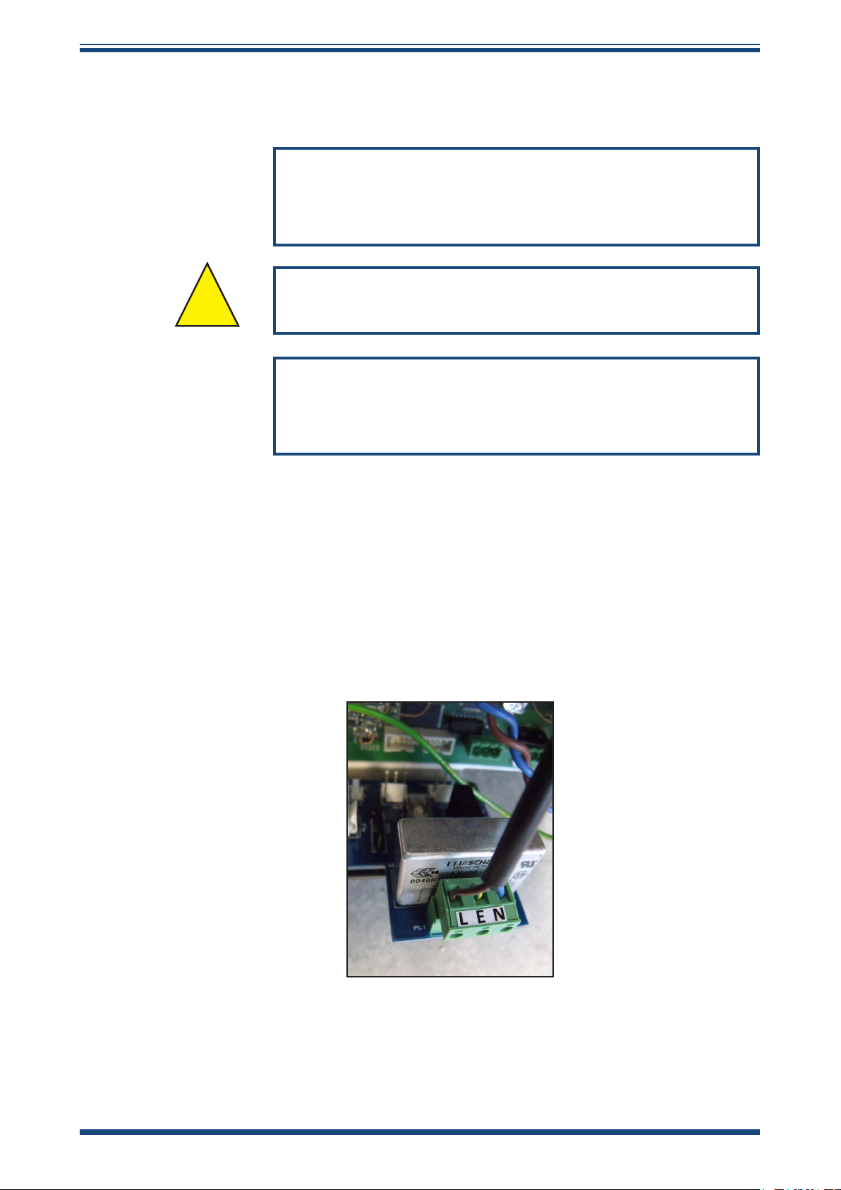
This equipment must be supplied with a voltage between the range of 90 to 260 V AC,
47/63 Hz. Maximum power rating is 125 W.
The power is connected via PL1 on the mains connector PCB.
Figure 1
All input and output connectors are 2-part PCB mounted type, rated at 300 V 10 A.
The detachable, screw terminal half of each connector is designed to accept 0.5 to
2.5mm2 [24 -12 AWG] stranded or solid conductors.
Power Connection Connector
Michell Instruments 5
Page 14
INSTALLATION
Any power connection cable should be 3 core over sleeved, with minimum 0.5mm
insulation and rated at 300 V. Cables should have Live (L), Neutral (N) and Earth
[Ground] (E) conductors. Ensure suitably rated power supply cables and glands are
used to ensure that electrical safety is maintained. Connect each of the Live (L), Neutral
(N) and Earth [Ground] (E) conductors to the similarly marked terminals (L, N, E) on the
Power In connector shown in Figure 1. Ensure the power supply can deliver sucient
power consumption requirement.
Any power supply terminals and voltages must be suitably separated from the other I/O
requirements of this product.
Before applying power, perform a continuity test to ensure that the power supply cable
and product are eectively connected to the protective Earth.
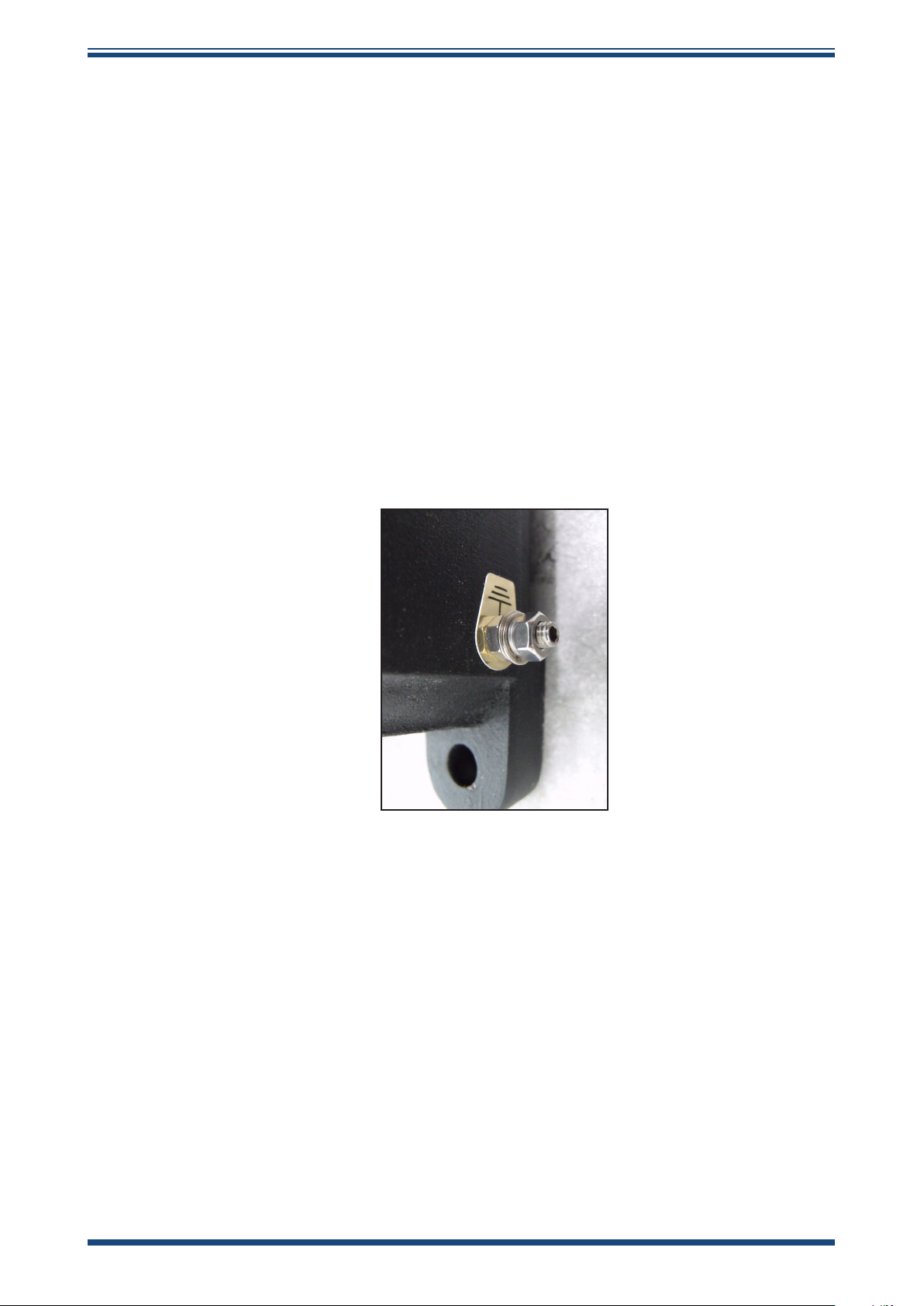
The Protective Earth terminal is mounted internally and the Earth wire connected to it
should never be disconnected. The product enclosure is supplied with an external earth
stud at the lower right hand side. At installation, connect this earth stud to plant earth
by a minimum 4mm2 earthing bonding. M6 stud and 2 o M6 nuts and washers, all
nickel plated.
Condumax II User’s Manual
Figure 2
Fuse: A replacement fuse can be obtained by contacting Michell Instruments' technical
support. Fuse rating = 5 x 20mm 2.5 A anti-surge to IEC 60127-2.
This product is designed to operate, as a minimum, between a temperature range of -40
to +60°C, in maximum 80% relative humidity for temperatures up to +31°C decreasing
linearly to 50% RH at +50°C. Supply voltages of ±10% and transient over voltages
up to Overvoltage Category II. Pollution Degree 2. Altitudes up to 2000m. Outdoor
mounting is permitted using suitably rated glands equivalent to NEMA 4 / IP66. See
Appendix A, Technical Specication for full operating parameters.
Do not remove or exchange any of the cables or electrical components supplied with
this product. Doing so will invalidate all warranties.
There are no additional or special electrical safety requirements other than those
referred to in this manual.
Earthing Stud And Nut Washer Assembly
6 97081 Issue 29.1, July 2019
Page 15

Condumax II User’s Manual
Location and mounting arrangements - refer to the relevant sections of this manual for
the location and mounting details.
Installation of this equipment must include the provision of a suitable and locally
positioned power isolation switch or circuit breaker. Indication of the purpose of the
switch or circuit breaker is strongly recommended. An over-current protection device
should be rated to a maximum of 10 A.
This equipment and all power isolation devices must be installed in a location and
position that allows safe and easy access to their operation and is able to rigidly support
the equipment.
Do not install this equipment in a location that would expose it to impact or high levels
of vibration.
Operation of this equipment, other than in a manner specied by the manufacturer, may
impair the safety protections provided.
The safe installation of this equipment and any system incorporating this equipment is
the responsibility of the installer. Ensure local regulations and requirements are referred
to prior to any installation commencing.
INSTALLATION
Michell Instruments 7
Page 16
INSTALLATION
!
2.2 Hazardous Area Safety
Refer to Appendix G for the Hazardous Area Certication of this product.
This product is tted with a marking label that contains Hazardous Area information
pertinent to the suitable location and installation.
During all installation and operation activities, local regulations and permitted working
routines must be observed. Installation should only be performed by competent personnel
and in accordance with the latest version of IEC/EN60079-14 or local equivalent.
Repair and servicing of this equipment must only be carried out by the manufacturer.
An Installation and Maintenance Information Sheet is supplied separately to the manual.
This product is certied safe for use in a Zone 1 and Zone 2
area only. This product must not be installed or used within
Condumax II User’s Manual
WARNING:
a Zone 0 area.
WARNING:
This product must not be operated within an explosive
atmosphere greater than 1.1 bara.
WARNING:
This product must not be operated with enriched oxygen
gas samples (more than 21% oxygen content).
WARNING:
This product must not be operated outside of the
temperature range of -40 to +59°C (-40 to +138°F).
WARNING:
The enclosure of this product provides Exd protection, partly
through the threads used for mounting the lid, stopping
plugs and cable gland. At all times eort should be made to
ensure these threads are suitably protected from damage
and that only appropriately rated mating parts are applied
to them, in accordance with the certifying requirements.
8 97081 Issue 29.1, July 2019
Page 17
Condumax II User’s Manual
!
!
!
2.3 Pressure Safety
This product is used in conjunction with pressurized gases.
Observe pressurized gas handling precautions.
Pressurized gas should only handled by suitably trained personnel.
INSTALLATION
WARNING:
WARNING:
Pressurized gas is dangerous.
This product requires pressurized gas to be connected to it. Observe pressurized gas
handling regulations. Only suitably trained personnel should carry out tasks that include
the use of pressurized gas mediums.
2.4 Lifting and Handling
Personnel must observe suitable lifting and handling precautions.
This product is not designed as portable or transportable equipment. It should be rigidly
xed in position as per the full installation instructions.
The weight of the analyzer is in excess of 18kg (40lbs). Therefore, appropriate lifting and
handling techniques should be used during the installation process. Before commencing
any lifting or handling ensure that its intended location is suitable and appropriately
prepared. Make sure that mounting point design considerations have employed locally
approved safety factors.
WARNING:
This instrument is in excess of 18kg (40lbs).
When handling and installing this product (particularly after removal from its packaging)
ensure that it is not dropped, impacted or subjected to high levels of vibration or
environmental conditions that may impair its operation.
Michell Instruments 9
Page 18
INSTALLATION
2.5 Measurement System
Refer to the Installation & Maintenance Information sheet (supplied separately) and the
System Drawings in Appendix A.
The instrument is housed in an aluminum EExd enclosure suitable for wall or panel
mounting. Four mounting points are available with M12 clearance holes on xing centres
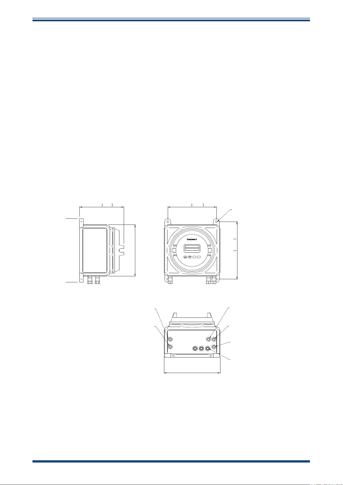
of X = 270mm (10.62") x Y = 318mm (12.51").
The dimensions of the enclosure are:
Height: 355mm (13.9”), 500mm (19.68”) including installation clearance
Width: 310mm (12.20”), 500mm (19.68”) including installation clearance
Depth: 245mm (9.64”)
The enclosure provides environmental ingress protection IP66/NEMA 4 and should be
mounted vertically in a location free of any appreciable vibration. It should be placed in
a shaded position to prevent heating eects through sun radiation.
Condumax II User’s Manual
The weight of the analyzer is 25kg (55lbs).
245mm 9.65"
290mm [11.41"]
Water Dew-Point Channel
1/8" NPT Female (ATEX/IECEx/CSA)
Hydrocarbon Dew-Point Channel
1/8" NPT Female (ATEX/IECEx/CSA)
Flame Arrestor
Flame Arrestor
270mm 10.63"
4 off M12 (1/2")
Clearance
318mm 12.52"
Enclosure Breather
Flame Arrestor
Do NOT obscure
Hydrocarbon Dew-Point Channel
Flame Arrestor
1/8" NPT Female (ATEX/IECEx/CSA)
Water Dew-Point Channel
Flame Arrestor
1/8" NPT Female (ATEX/IECEx/CSA)
Cable Entry Glands
3 off M20 (ATEX)
3 off M20 -> 1/2" NPT Thread Adaptor (CSA)
Figure 3
310mm [12.20"]
Condumax Dimensions
10 97081 Issue 29.1, July 2019
Page 19
Condumax II User’s Manual
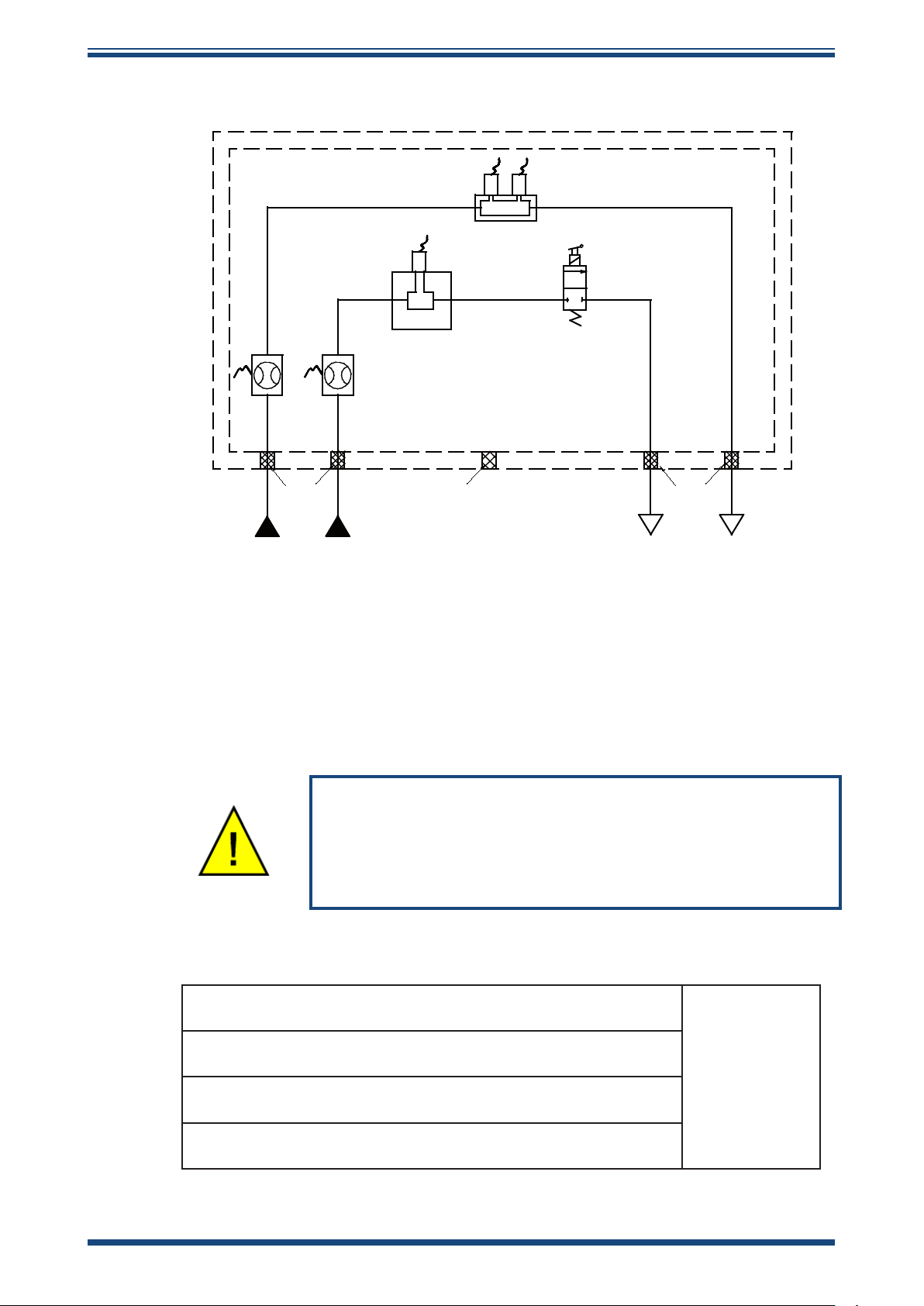
FLOW
FLOW
PRESSURE
PRESSURE
GAS SAMPLING BLOCK
HYDROCARBON
DEW-POINT
SENSOR CELL
MICHELL WATER
DEW-POINT SENSOR
GAS IN
GAS IN
GAS OUT
GAS OUT
FLAME
ARRESTORS
FLAME
ARRESTORS
SOLENOID VALVE
TRANSMITTER
TRANSMITTER
SWITCH SWITCH
MAX. 138/206 BARG MAX. 100 BARG
ENCLOSURE BREATHER
(DO NOT OBSTRUCT)
1
12
2
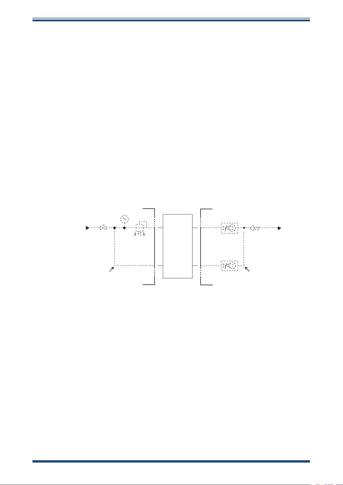
2.5.1 Gas Connections, Sample Extraction & Conditioning
INSTALLATION
NOTE: Ensure that the process sample gas supply line is well ushed through
to clear any liquids and debris present prior to connection to the instrument. A
sample handling system must prepare the gas in terms of pressure regulation
and ltration before entering into the measurement system.
The pipe work connections are as follows:
Figure 4
Flow Schematic
In accordance with the certication requirements for safe
operation of this product, the Condumax II must have, as a
minimum, those components described in Section 2.7 and
Hydrocarbon gas sample inlet
positioned as shown in Appendix A.1.
(Maximum pressure of 100 barg (1450 psig))
Hydrocarbon gas sample outlet
(Vent to atmosphere or low pressure flare line)
Water dew-point gas inlet
(Maximum pressure of 138 barg (2000 psig))
Water dew-point gas outlet
(Vent to atmosphere or low pressure flare line)
1/8" NPT Female
(ATEX/IECEx/
CSA)
Michell Instruments 11
Page 20

INSTALLATION
The following points should be considered when installing the sample gas supply line:
PTFE tape is recommended for pipe connections. Solvent based pipe thread sealant
should not be used, as condensable components or contaminates can be leached during
the curing period.
It is recommended that Viton is used for all O-rings.
Care and attention to the position and installation of the piping will minimize problems
caused by avoidable contamination of the measurement system. The most common
cause of diculty is the accumulation of liquid in impulse lines during a shutdown
period. If the measurement system has not been isolated on restart-up, condensate
can be displaced into components and associated pipe work within the measurement
system.
If this event follows a period when process lines may have been contaminated by nonhydrocarbons e.g. glycol, corrosion inhibitors etc., the problem is magnied. Similarly,
diculty will be encountered in sample gases carrying liquids, including hydrocarbon
liquids.
Condumax II User’s Manual
Our recommendations are:
• The sampling point on the process line should be on the top of the pipe.
If a radial probe is used the orice should face downstream.
• The internal volume of the impulse tubing between the process line and
any sampling system should be as low as possible to minimize response
lag time to changing process conditions.
• Piping should be lagged and/or trace heated if ambient temperatures
could cause the sample gas to fall below its dew-point temperature.
• A drain valve should be placed at the low point (if any) in the system.
• It should be standard procedure to isolate the measurement system
during shutdowns or when plant problems are being experienced and to
properly purge the supply lines before restarting.
• The relatively large area of surfaces and internal volume of pressure
regulators can be particularly troublesome if contamination is experienced.
Prolonged purging with gas may be necessary to remove the contamination.
Stripping and cleaning followed by purging of the system is preferred.
• Avoid sample gas streams that are already very close to the dew point
or which have dispersed liquid (not necessarily hydrocarbon) burden. In
such cases, sampling from fast loops and/or from downstream of existing
catch pot/coalesce systems is always preferred.
Failure to observe these recommendations will potentially cause problems of
contamination as well as causing consequential inaccurate, unreliable and inconsistent
monitoring. If a top-entry sample point is not available, extra attention should be given
to the design of the sample line installation to avoid unwanted contamination.
12 97081 Issue 29.1, July 2019
Page 21

Condumax II User’s Manual
Sample Extraction and Conditioning
Sample extraction, handling and conditioning techniques are of critical importance
to assure optimal performance and reliability of all gas analyzers which accurately
quantify specic components within a process gas composition. Michell Instruments'
recommendations and requirements in relation to the Condumax II are outlined below.
Michell Instruments oers a range of sample conditioning systems which are designed to
exceed these minimum requirements. For further information and advice please contact
your local Michell oce or distributor – See contact details on www.michell.com.
Sample Extraction and Impulse Tubing
An insertion probe, with tip positioned within the central 1/3rd of the cross sectional
area of the pipe, should be used to derive a sample composition that is representative
of the majority of gas owing within the pipeline.
Attention should be given to the installation of impulse tubing connecting from sample
probe to the analyzer sample conditioning system. Analytical grade acid-etched
stainless steel tubing should be used, which has a low moisture sorption capacity. Tube
size should not be larger than ¼” or 6mm outside diameter to ensure that sample
transportation delay time is kept to a minimum. Likewise, to ensure best dynamic
response of the complete installed analyzer system, the positioning of the analyzer with
sample conditioning system should be as close as possible to the sample extraction
probe.
INSTALLATION
To avoid any risk of condensation forming during transportation to the analyzer, and so
ensure the integrity of the sample gas is maintained, the temperature of the sample
impulse tubing must be maintained at a temperature above the highest envisaged
water dew point. It is recommended that the sample tubing temperature is maintained
at least 5°C (10°F) above the maximum water dew point at the prevailing pressure, as
a suitable ‘safety margin’. Self-limiting heating cable should be applied to the complete
length of the impulse tube, enclosed within suitable insulation. The power rating of
heating cable should be selected to achieve the required maintained temperature given
the minimum climatic temperature at the installation location. For convenience during
installation, a number of leading process electric heating companies oer tube ‘bundles’
comprising instrumentation tubing, self-limiting heating cable, insulation and protective
outer sheath. Trace heated tube bundle is a factory tted option for Michell produced
sample conditioning systems.
Sample Conditioning
The sample conditioning system must address the needs for ltration, pressure reduction
and sample ow control.
To maintain cleanliness of the analyzers optical detection system, the process sample
ow must be ltered to eliminate entrained liquids and particles. To provide protection
against HC condensates and compressor oils that may be present in process natural
gas, it is recommended to use micro-porous membrane ltration with an oleo-phobic
element specically intended to reject such low-surface tension liquids.
Michell Instruments 13
Page 22
INSTALLATION
Pressure reduction and sample ow control is required to achieve the desired analysis
pressures and the stated sample ow requirements of the analyzer – see Section 2.7.
Care should be taken to counteract though directly applied heating the Joule-Thomson
cooling eect of sample expansion to reduced pressure. Established business practice
at custody transfer is to measure water dew point at full line whilst HC dew point is
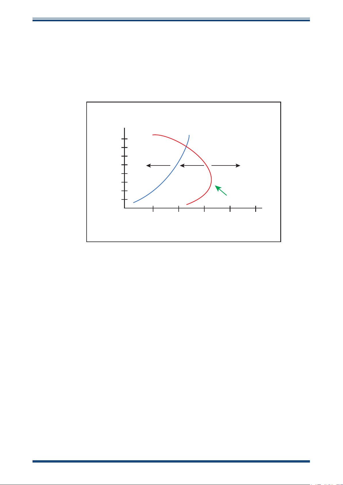
determined at intermediate pressure, commonly 27 barg (400 psig), the cricondentherm
condition at which HC dew point temperature will be highest on the retrograde phase
envelope – see gure below:
Condumax II User’s Manual
H2O Dew Point
8
7
6
5
Water and
4
HC liquids
3
2
1
0
preset in
gas
-30-40 -20 -10 0 +10
Pressure MPa
HC liquids
present in
gas
HC Dew Point
Wholly gaseous
Cricondentherm
Temperature °C
Figure 5
Typical Phase Envelope for Northern Europe Natural Gas
As with the sample impulse tubing, the sample conditioning system (SCS) must be
maintained at a temperature above the highest expected water and HC dew point at
the prevailing process sample pressure and the analysis pressure for HC dew point,
either by housing the SCS together with the analyzer within a heated and thermostatic
controlled, insulated enclosure, or by positioning in a suitable indoor environment. The
enclosure for outdoor installed systems must be located within 100% shade from direct
sun, if necessary by the addition of an eective sun canopy with walls on three sides.
As with all precision analytical equipment, it is desirable to maintain a moderate operating
temperature. In the specic case of a HC dew-point analyzer, care should be taken not to
elevate the analyzer operating temperature higher than is necessary to maintain sample
integrity. Given the principle of cooled-mirror dew-point measurement, the measurement
range of HC dew point is limited by a cooling depression range capability. In the case
of the Condumax II, the lower range capability is >=50°C from the prevailing analyzer
operating temperature. When the analyzer system is installed outside in hotter climate
installation locations, or where the application requires measurement near or below the
measurement cooling depression limit, it may be necessary to provide auxiliary cooling
within the system enclosure. Such cooling can be achieved using a compressed air
driven vortex tube controlled by an adjustable thermostat.
14 97081 Issue 29.1, July 2019
Page 23
Condumax II User’s Manual
2.5.2 Power Connection
A single-phase AC power connection is required.
The power supply can accommodate voltages from 90 to 260 V AC, 47/63 Hz. The unit
requires a maximum of 125 W to function correctly.
Cable entry into the measurement system is made through the bottom of the enclosure.
• For ATEX/IECEx compliant versions of the product 3 o ISO M20 tapped
holes are provided.
• For CCSAUS compliant version of the product 3 o M20 -> 1/2" NPT thread
adaptorare provided.
Power connections are made via a removable screw terminal connector mounted on the
mains connection PCB.
INSTALLATION
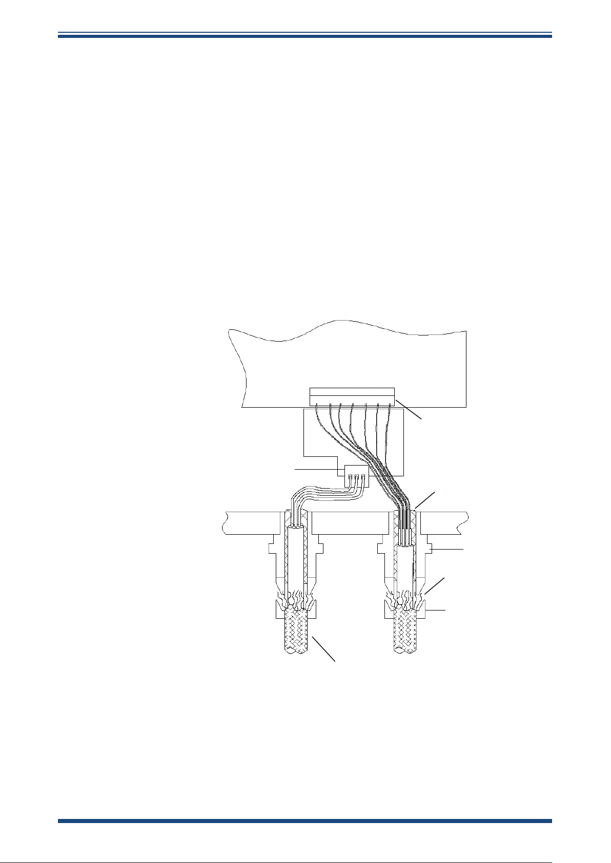
Terminals are marked:
L = Live
N = Neutral
E = Earth/Ground
Power supply
connector
0VAB
1 2 3 4 5 6 7
mA2-
L E N
mA2+
mA1-
mA1+
COMMS connector
Foil screens
fold back
to gland
Earth/Ground
Barrier gland
Braided screen
Gland
Earthing/Grounding
Collar
Connecting cable to be
compliant with
Special Conditions for Use
stipulated within the
ATEX & IECEx Certificates
Figure 6
Wiring Hook-Up Diagram
Michell Instruments 15
Page 24

INSTALLATION
2.5.3 Analog and Digital Communications
Two active 4-20 mA outputs and a Modbus RS485 digital interface (see Appendix B for
details) are provided with the Condumax II. The 4-20 mA outputs can be set individually
to represent one of the following:
• Hydrocarbon dew point (or signal in mV if in condensate mode)
• Hydrocarbon dew-point analysis pressure
• Water dew-point analysis pressure
• Water dew-point temperature (or moisture content)
NOTE: The maximum output resistance for the 4-20 mA outputs is 500 Ω.
Condumax II User’s Manual
Refer to Section 3.10.4 for the setting of the 4-20 mA outputs via the user interface and
refer to Appendix B.4 on setting the outputs via the Modbus interface.
16 97081 Issue 29.1, July 2019
Page 25
Condumax II User’s Manual
2.6 Condumax II Start-Up Purge Procedure
This is a mandatory procedure stipulated in the ATEX/IECEx
certication of the product. The procedure must be fully
carried out prior to the Condumax II having any power or
signal connections applied. It must also be fully carried
out after the Condumax II and associated gas handling
equipment has been installed and leak checked. Always
refer to Appendix G.4 - Special Conditions of Safe Use.
This procedure must be carried out at any time following
service or maintenance periods that cause any of the
Condumax II or associated gas handling equipment pipe
work to be disconnected.
It is not necessary to carry out this procedure if power or
signal connections only, have been disconnected.
INSTALLATION
1. Before start-up, ensure that all power and signal connections to the
Condumax II are fully isolated.
2. Ensure that all inlet & outlet gas connections to the Condumax II are
correct and leak tight checked.
3. Fully open the ow control valve of the owmeter on the hydrocarbon
dew-point channel and, if also tted, the water dew-point channel.
4. Set the solenoid valve to the PURGE position (fully screwed in clockwise)
by using the manual override operating adjuster mounted on the
base of the solenoid valve body. Indication of the manual override position
is shown on a label attached to the solenoid Access to the solenoid valve
is obtained by removing the enclosure cover. Refer to Section 4.2 for
removal and retting of the enclosure cover.
The manual override operating adjuster is provided
only to allow initial system set-up and purge in an
unpowered condition. This manual override adjuster
must never be operated while in a pressure induced
condition. The manual operation of the valve is not
required for the normal operating cycle of the system.
5. Fully open the sample gas inlet isolation valve.
6. Gradually open the pressure regulator until full scale ow is observed on
the hydrocarbon dew-point channel owmeter and the water dew-point
channel owmeter, if tted.
Michell Instruments 17
Page 26
INSTALLATION
HYDROCARBON
DEW-POINT
CHANNEL
WATER DEW-POINT
CHANNEL
GAS IN GAS OUT
GAS IN GAS OUT
CONDUMAX II
See NOTE 2
FLOWMETER
FLOWMETER
NON-RETURN
VALVE
GAS OUTLET
GAS INLET
ISOLATION VALVE
PRESSURE
GAUGE
PRESSURE
REGULATOR
GAS INLET
NOTE:
1. Connecting pipework to be 4mm I/D bore, 316L stainless steel tube
2. Components and pipework only required if water dew-point channel is installed into Condumax
See NOTE 2
7. Allow the sample gas to purge the system for the period of time indicated below:
• Total purge time must be a minimum of 1 minute at 1 Nl/min (0.06
• For every additional meter of 4mm internal bore pipe work of a
8. After the appropriate purge duration the gas inlet isolation valve may be closed.
9. Return the manual override valve adjuster on the Solenoid to the NORMAL
OPERATING position (fully unscrewed counter-clockwise).
10. The enclosure cover may now be replaced. NOTE: Before any power or signal
lines are connected the enclosure cover must be fully tted.
11. After the enclosure cover has been retted the Condumax II is ready for immediately
start-up. NOTE: If start-up is delayed then the purge procedure must be
repeated.
Condumax II User’s Manual
Nm3/hr) (2.1 scfh).
Assumes total system (see diagram below) pipe length is 3m (9.8ft)
and internal pipe bore is the recommended 4mm internal bore.
sampling system, continue the gas purge for an additional 15
seconds at 1 Nl/min (0.06 Nm3/hr) (2.1 scfh).
Figure 7
Minimum Requirements for Start-Up Purging
2.7 Sample Gas Flows
The sample gas ows for the system should be set as follows:
• For the hydrocarbon dew-point channel it is recommended that a ow of
approximately 1 Nl/min (0.06 Nm3/hr) (2.1 scfh) is set. This ow setting
gure is not required to be precise as its purpose is only to ensure that
18 97081 Issue 29.1, July 2019
a representative sample of gas is presented to the measurement sensor.
During the measurement cycle the sample gas ow is isolated as the
measurement is made in a static ow condition.
Page 27
Condumax II User’s Manual
• To increase the speed of response of the measurement of the main
process gas it is highly recommended that a fast bypass loop is installed
into the gas sampling system. The recommended ow through the bypass
loop should be typically 3 to 4 times that of the hydrocarbon channel.
Therefore, typically, the bypass gas ow should be set to approximately 3
to 4 Nl/min (0.18 to 0.24 Nm3/hr) (6.3 to 8.5 scfh).
• If a water dew-point channel is tted, the gas ow through its sensor
should be set at approximately 3 Nl/min (0.18 Nm3/hr) (6.3 scfh).
2.8 Sample Flow Alarms
The ow switches are supplied to alert the user to either
severely reduced or discontinuation of sample gas ow
INSTALLATION
through the system.
An alarm state will be indicated on the Error Message line at the bottom of the MAIN
display. Refer to Section 4.6 for further details.
After the correct ow of sample gas is set, the alarm states will be indicated when the
gas ow has fallen below that required to make eective measurements.
The ow switches tted are adjusted during factory test to activate the alarm when
the ow falls below approximately 20 to 10% of the normal recommended sample ow
setting (see Section 2.7). During the factory setting procedure the gas pressure that is
applied represents the most common application analysis conditions for hydrocarbon
(27 barg (391 psig)) and water (68 barg (986 psig)) dew-point sensors.
The operation of these variable area ow switches are inuenced by pressure. For
increased pressure the ow alarm activation point will be at a higher ow rate and
conversely, for reduced pressure, the activation point will be at a lower rate. These
devices exhibit a hysteresis that may require a ow of greater than 100% of the
recommended ow setting for a brief period in order to clear the alarm condition.
NOTE: If the Condumax II main unit is going to be operating with signicantly
dierent analysis pressures to those used during factory testing, then ne
re-adjustment of the ow switches may be benecial to suit the application
conditions. If this is the case contact Michell Instruments (www.michell.
com) for guidance as to how adjustments can be made on site.
Michell Instruments 19
Page 28

OPERATION
3 OPERATION
At switch-on, the system synchronizes to the on-board real-time clock, heats the optical
surface to the set-point temperature and adjusts the optical levels to give a signal
level of 0.00%. When the ‘next measurement’ time counts down to 0 minutes and 0
seconds, the measurement cycle commences and the system cools the optical surface
at a controlled rate until the signal level increases to 100% of the trip point. Once
reached, the optical surface temperature is recorded as the hydrocarbon dew point,
along with the hydrocarbon channel pressure, water dew point (if this option is tted)
and water channel pressure. The optical surface is then heated to the set-point and
the optics level is re-adjusted to give a signal level of 0.00%. The cycle is repeated
continuously at ‘cycle time’ intervals, which are factory set at 10 minute intervals but
may be user adjusted.
3.1 Timing Synchronization
At switch-on, the instrument will display the MAIN page (Section 3.6) and synchronize
itself to the on-board real time clock, in order to start the measurement cycles at a
time (hrs:mins) that is divisible by 10 - i.e. 10, 20, 30, 40, 50 or 60 (0). If the rst start
time is less than 2 minutes away, then the system will start measurements on the next
permissible start time. For example, if the instrument is switched on at 6 minutes past
the hour, then the instrument will take its rst measurement at 10 minutes past the
hour. However, if the instrument is switched on at 9 minutes past the hour, then the rst
measurement will begin at 20 minutes past the hour, to ensure there is enough time for
the system to auto-calibrate itself.
Condumax II User’s Manual
3.2 Recovery Phase
Auto-calibration commences at switch-on and after every measurement cycle. The
sensor mirror is heated to the mirror temperature set-point and the optics level is
adjusted to give a signal level of 0.00%. This procedure is shown on the STATUS Page
where the mirror temperature, signal and optics values can be observed.
3.3 Measurement Phase
The Condumax II can be set to function in one of 2 modes - Condensate Mode and
Measurement Mode are mutually exclusive. One is the inverse of the other.
Measurement Mode: HC dew-point temperature at a set trip point (threshold for
signal change, mV). This is the normal operating mode for the analyzer.
Condensate Mode: Signal change (mV) at a customer set cooling trip temperature.
This mode can be applied temporarily by the user if harmonization of HC dew-point
temperature measurement sensitivity to a desired reference value is required. As an
example, the Trip Temperature could be set to the user's reference HC dew point
temperature in order to determine, through a series of Condensate Mode measurements,
the Signal Change 9mV0 setting required in order for Condumax II to replicate the same
measured value in normal Measurement Mode operation. For further information refer
to section below.
• Measurement Mode
When the phase duration time reduces to 0 minutes and 0 seconds, as
shown in the bottom line of the MAIN and STATUS Pages, the system will
deactivate the internal sample solenoid valve to stop the gas sample ow and
reduce the temperature of the mirror at a controlled rate until the signal level
has increased to 100% of the signal level trip point (refer to Appendix D.1).
Once this detection threshold is reached the optical surface temperature will
be reported as the HCdp.
20 97081 Issue 29.1, July 2019
Page 29

Condumax II User’s Manual
During every measurement cycle, and based on the previous measurement,
the optical surface temperature ramp rate is optimized to be at 0.05°C/sec
at the point of hydrocarbon dew-point measurement.
After the signal trip point has been reached, the system will re-enter the
Recovery Phase, control the temperature of the optical surface to the
set-point, adjust the signal level to 0.00% and count down to the next
Measurement Phase.
• Condensate Mode
When the phase duration time reduces to 0 minutes and 0 seconds, the
system will deactivate the internal solenoid valve and cool the optical surface
at a controlled rate until the the user set trip temperature is reached. This
mode provides a method to observe signal change to a dened temperature
(user-set trip temperature - refer to Appendix D.1), whereby the change in
optical detection signal is recorded and displayed in mV.
The duration of the Recovery Phase in both modes is dependant upon the time taken to
reach the trip point or temperature and the duration between measurements. Typically,
for factory-default 10 minute cycle time, the measurement cooling duration is 2 to 3
minutes with the remaining 8 to 7 minutes Recovery Phase.If the system does not reach
the trip point or temperature, then the system will re-enter the Recovery Phase after
the maximum cooling time has expired.
OPERATION
3.3.1 Water Dew-Point Measurement
If a water dew-point sensor is tted, the instrument will detect its presence at switch-on
and display both water and hydrocarbon dew point and pressures as shown in Section
3.12. The water dew point and water dew-point pressure readings are updated at 1
second intervals.
3.3.2 Signal Changes and Trip Point
The measurement circuits within the instrument are very sensitive and are capable of
sensing ųV changes in the optical detection circuit. When condensate forms on the
optical surface of the sensor, the received light level progressively falls and is seen on
the status page as an increase in signal change This is dened as sensor optical surface
wet-out. The smallest detectable signal changes can be regarded as the inception
of condensate formation. However, for mixed hydrocarbon gas streams where a tail
of heavy components is present, this initial change is of little signicance since the
amounts of condensate are minute and are often undetectable by sensitive chemical
analysis methods such as gas chromatography.
The magnitude of the change in the optical detection circuit is a function of the quantity
of condensate formed on the sensor surface. Therefore, a signal change threshold can
be set which corresponds to some signicant condensate quantity; this threshold level is
referred to as the ‘trip point’. A ‘trip point’ value can be selected to produce a measured
dew-point temperature which agrees with the value predicted by the extrapolation of
the linear regression plot of liquid/gas ratio (LGR as a function of temperature) to zero
condensate for the gas stream under test.
Michell Instruments 21
Page 30

OPERATION
As the detection principle of the Condumax II is essentially quantitative it can itself be
utilized to produce a graphical representation akin to the LGR relationship that can then
be used to judge the ‘trip point’ required for the specic gas under test. Refer to Section
3.3.3 on sensitivity calibration.
In applications at monitoring points where a specic analysis method is stipulated
in a contractual specication, e.g. a manual visual optical dew-point measurement
instrument, then an alternative method is to select a ‘trip point’ value that corresponds
to the maximum dew-point found by repeated and careful measurement using the
stipulated method. In practice, the factory default setting for the ‘trip point’ of 275 mV
for analysis pressure at 27 barg should prove satisfactory if no detailed calibration is
available and will return a measured dew-point 0.5 to 1°C above the value obtained
from manual visual optical techniques applied by an experienced operator observing
best practices (ASTM, D1142). An analysis adjustment to 27 barg is the most common
measurement practice when monitoring transmission quality gas, in order to determine
HC dew-point at the cricondentherm condition (highest temperature at which a twophase equilibrium will exist on the phase envelope). Analysis at an alternative pressure
may require adjustment of the trip point to a revised setting, in order to maintain
a consistent sensitivity of analysis. If an alternative analysis is stipulated in the
measurement practices or contractual gas quality specications relevant to a specic
application for Condumax II, please contact Michell Instruments for advice.
Condumax II User’s Manual
The processes and signal changes that occur during the formation of condensate on
the sensor surface can be monitored using Modbus RTU digital communications via PC
software. Contact Michell Instruments (see www.michell.com) for more information.
Care should be taken if checking the span of the signal change when using a rich binary
test gas, as a very rapid change in the signal will result in an optical surface wet-out.
3.3.3 Sensitivity Calibration
When a sensitivity calibration is initiated (Section 3.11), the system will check to ensure
the optical surface temperature is within 1°C of the optical surface temperature setpoint and the signal is 0.00%. Once these conditions are met, the system will decrease
the optical surface temperature at a controlled ramp rate until the signal has reached
100% of range (1500 mV), or after 10 minutes if 100% cannot be reached.
In order for the system to compute the required optical surface temperature ramp
rate, it cools the optical surface down to the Sensitivity Calibration Temperature that is
computed from the last hydrocarbon dew-point measurement. This can be changed for
diagnostic purposes by the user interface controls.
Once the sensitivity calibration is complete, a table of signal sensitivity vs. temperature
is displayed by the instrument or can be downloaded by the Modbus communications
to be plotted on a graph.
From the graph below, the signal trip point can be determined by cross-referencing the
known dew point of the gas to a sensitivity value. This sensitivity point should then be
entered into the instrument as the signal trip point, so that, during the Measurement
Phase, the instrument will record the temperature of the optical surface (HCdp) when
the signal reaches the signal trip point.
22 97081 Issue 29.1, July 2019
Page 31

Condumax II User’s Manual
1500
1400
1300
1200
1100
1000
900
800
700
600
500
400
300
200
100
0
-20 -10 0 +10
MIRROR TEMPERATURE Deg C
SIGNAL LEVEL mV
OPERATION
Figure 8
Sensitivity Calibration Plot (Example)
As shown above, the least squares regression of this plot can be utilized to set the Trip
Point. i.e. instrument measurement sensitivity. In the case shown a trip level of 275
mV would be determined.
3.3.4 Adjustment of Measurement Sensitivity to User Defined Reference
Condensate mode (see Section 3.3) is a useful feature if the customer decides to ‘ne
tune’ the Trip point to achieve a harmonized reading with a secondary measurement
device (such as Bureau of Mines dew-point apparatus applying ASTM D1142 method).
Secondary measurement device reads x HC dew point at pressure y (which must be
the analysis pressure required on the Condumax II). Set Condumax II to analysis
pressure y, and operate in Condensate Mode with Trip Temperature set to x, the value
measured by the secondary measurement devise. Allow the Condumax II to perform
at least 3 measurement cycles to assure measurement stability with constant sample
gas composition and optimum measurement cooling rate, <0.1°C/sec (observed in the
Status Page). Implement the harmonization of measurement sensitivity adjustment by
returning the Condumax II to normal Measurement Mode and setting the Trip Point to
the signal change mV value obtained in Condensate Mode.
The facility to adjust the Trip Point setting allows the user to harmonize on-line process
measurement sensitivity of the Condumax II with customer’s preferred reference
method or to achieve conformance with any relevant regulatory standards that may
apply, most typically:
1. Bureau of Mines chilled-mirror dew point apparatus applying ASTM D1142.
2. Potential Hydrocarbon Liquid Content analysis (PHLC) applying ISO6570.
Michell Instruments 23
3. Measurements of synthesized natural gas mixture of certied composition
with prediction of HC dew-point temperature from equation of state
calculation.
Page 32

OPERATION
3.4 User Interface
3.4.1 Interface Controls
Condumax II User’s Manual
Condumax II
Hydrocarbon Dew-point Analyzer
-11.0 0CHCdp
27.0 BarG
@
-32.5 0CWdp
@
69.0 BarG
NEXT MEASUREMENT: 0m 11s
VFD Display
Blue LEDs
MENU
MAIN
MENU/
MAIN
Button
Up/Down
Arrow
Buttons
SELECT
SELECT
Button
Figure 9
User Interface
The diagram above illustrates the user interface, which consists of a vacuum uorescent
display and four touch sensitive pads that facilitate user interaction through the glass
of the enclosure.
3.4.2 ‘Up/Down Arrow’ Buttons
Figure 10
‘UP/DOWN ARROW’ Buttons
The Up () and Down () buttons are used to change pages, scroll through lists and
adjust values.
24 97081 Issue 29.1, July 2019
Page 33

Condumax II User’s Manual
3.4.3 ‘SELECT’ Button
OPERATION
SELECT
The SELECT button is used to select or de-select a highlighted item in a menu list.
3.4.4 ‘MENU/MAIN’ Button
The MENU/MAIN button is used to toggle between the MAIN page and the MENU
page, or return to the MAIN page from any location within the menu structure.
Figure 11
Figure 12
‘SELECT’ Button
MENU
MAIN
‘MENU/MAIN’ Button
Michell Instruments 25
Page 34

OPERATION
3.5 Menu Structure
The diagram below shows a map of the menu structure:
KEY
Choices
Menu Pages
Other Pages
Start Up
Banner
Main Page
MENU
MAIN
Condumax II User’s Manual
MENU
MAIN
Press MENU/MAIN button to
get back to Main Page from
any location (unless instrument is
executing sensitivity calibration)
MENU
MAIN
Menu Page
NO
Status Page
1
Status Page
2
SELECT
Error ?
YES
Error Report
Page
SELECT
STATUS
SELECT
View
Logged
Data
SELECT
LOG MENU
SELECT
View
Statistics
SELECT
Statistics
Page 1
Statistics
Page 2
Statistics
Page 3
Statistics
Page 4
View
System
Faults
SELECT
Logged
Error Codes
VIEW/ADJ
VARIABLES
SELECT
Password
Page
NO
SENSITIVITY
SELECT
Password
Correct?
YES
Variables
Page 1
CAL
Execute
Sens Cal
SELECT
Sensitivity
Cal Menu
WATER DP
SELECT
View Sens
Cal Data
Sensitivity
Cal Data
SENSOR
SELECT
CONTACT/
ABOUT
SELECT
Sensor 1 Sensor 2
SELECT
Sensor 1
info
SELECT
SELECT
Sensor 2
info
Contact Info
Variables
Page 2
Variables
Page 3
Variables
Use Up/Down arrow buttons
to scroll through
menu items and pages
Page 4
Variables
Logged Data Pages
Figure 13
Page 5
Menu Structure
26 97081 Issue 29.1, July 2019
Page 35

Condumax II User’s Manual
3.6 Main Page
OPERATION
0.0 0CHCdp
@
0.0 psig
6.4 0CWdp
@
NEXT MEASUREMENT: 7m 45s
Figure 14
NEXT MEASUREMENT: 9m 5s
Figure 15
The MAIN page displays the measured parameters and the instrument’s operational
status. The information shown is dependent upon whether a water dew-point sensor is
tted or not, as shown above. If a water dew-point sensor is tted, then dew points for
hydrocarbon (°C HCdp) and water (°C Wdp) will be shown along with their associated
pressures, otherwise only dew point and pressure for hydrocarbon will be displayed.
0.0 psig
MAIN Page With Wdp Sensor Fitted
7.7
0.0 psig
MAIN Page Without Wdp Sensor Fitted
0
CHCdp
The text in the bottom line indicates the time duration until the next Measurement
Phase and any system faults that may occur. See Section 4.6 for more information on
system faults.
NOTE: When in condensate mode, the measured value displayed will be the
signal level (x10) mV, i.e. 4.0 = 40.0 mV, at the user-set trip temperature.
3.7 Menu Page
Access to the instrument’s status, variables, logged data and system information is
available through this page. Use the Up () and Down () buttons to highlight the
page of interest and press the SELECT button to access.
MENU
STATUS
LOGGING MENU
VIEW/ADJ VARIABLES
SENSITIVITY CAL
WATER DP SENSOR
CONTACT INFO
Figure 16
Michell Instruments 27
MENU Page
Page 36

OPERATION
3.8 Status Pages
STATUS PAGES 1 and 2 provide status and diagnostic information from the instrument.
3.8.1 Status Page 1
Condumax II User’s Manual
STATUS PAGE 1/2
o
MIRR TEMP 50.1
C
SIGNAL 0.00 %
OPTICS 9.10 %
o
COOLING 0.00
C/S
SOL DRIVE ON
NEXT MEASUREMENT: 2m 11s
Figure 17
STATUS Page 1
MIRR TEMP Display term which refers to the Optical Surface and is an abbreviation
for ‘mirror temperature’. This is the surface upon which the actual
hydrocarbon dew-point measurement is made, and the temperature
displayed is the current real-time temperature of the optical surface
(MIRR TEMP). During the Recovery Phase the optical surface
temperature will rise to the set-point temperature and, during a
Measurement Phase, the temperature will decrease at a controlled
rate until the HCdp is reached. See Appendix D.4 - Heat Temp - for
more details.
SIGNAL Measured signal from the sensor, which is displayed as a percentage
of the trip point.
OPTICS Measure of the condition of the optical surface. Typically a clean optical
surface will be indicated by a measurement of between 2 to 10%. If
contamination accumulates on the optical surface the % value will
increase.
COOLING Cooling rate of the mirror during the Measurement Phase. It is updated
every second during the Measurement Phase, but holds its value when
the trip point is reached, until the next Measurement Phase begins.
SOL DRIVE Drive to solenoid, and is either ON or OFF. During the Measurement
Phase the solenoid drive is OFF. During the Recovery Phase the
solenoid drive is ON.
28 97081 Issue 29.1, July 2019
Page 37

Condumax II User’s Manual
3.8.2 Status Page 2
WDP ALARM : OFF
HCDP ALARM : OFF
HCDP FLOW : OFF
WDP FLOW : OFF
INT TEMP : 25.3
NEXT MEASUREMENT: 2m 6s
STATUS PAGE 2/2
OPERATION
O
C
Figure 18
STATUS Page 2
WDP ALARM Water dew-point alarm status, will display either ON or OFF.
If the water dew point rises above the WDP set-point, ON will be
displayed.
When the water dew-point channel is not tted the indication will
continuously display OFF. See Appendix D.3 for more information on
setting alarm set point.
HCDP ALARM Hydrocarbon dew-point alarm status, will display either ON or OFF.
If the hydrocarbon dew point rises above the HCDP set-point, ON will
be displayed. See Appendix D.3 for more information on setting alarm
set point.
HCDP FLOW Hydrocarbon dew-point ow switch status - displays ON during the
Recovery Phase and OFF during the Measurement Phase.
WDP FLOW Water dew-point ow switch status, either ON or OFF.
When the water dew-point channel is not tted the indication will
continuously display OFF.
INT TEMP The internal temperature within the instrument.
Michell Instruments 29
Page 38

OPERATION
LOGGED DATA
HCDp 6.2
o
C
HCDp Pr 0.0 Psig
WDp 0.3
o
C
WDp Pr 0.0 Psig
NO. 1 10:20 29/06
Sample Number Time of Sample
Date (no year)
Values
Measurement Units
3.9 Logging Menu Page
This page allows the viewing of the logged data or statistical information on the logged
data.
3.9.1 Logged Data Page
This page allows access to the previous measurement results made by the instrument.
A rolling total of a maximum of 150 samples can be logged, which represents a
measurement history of 150 x (measurement time) in minutes. Sample number 1
represents the most recent measurement taken. After 150 measurements have been
logged the oldest measurement will be deleted and replaced as each new measurement
is logged.
Access to each measurement sample is via the Up () and Down () buttons, which
may be used to scroll through each page of information. If faster scrolling is required
(to quickly move to another sample) then this can be accomplished by pressing the
SELECT button, increasing the sample number by 10. When the sample number selected
is greater than that acquired or is greater than 150, Sample 1 will be selected and
displayed.
Condumax II User’s Manual
Each page of sampled data contains:
Sample number (1 to 150; 1 being the most recent)
Date of sample (dd/mm)
Time of sample (24 hr format, hh:mm)
The values of HCdp, Wdp, HCdp Pr and Wdp Pr
The units of measurement
30 97081 Issue 29.1, July 2019
Figure 19
LOGGED DATA Page
Page 39

Condumax II User’s Manual
3.9.2 Statistics
These pages display the maximum, minimum and average values for each measured
parameter for up to 150 previous measurement samples. RESET LOG re-sets the
logging statistics.
STATISTICS PAGE 1/4
HCDp Max -3.0
at 23:10 on 07/12
HCDp Min -21.2
at 07:20 on 01/04
OPERATION
o
C
o
C
HCDp Avr -13.7
Figure 20
Use the Up () and Down () buttons to scroll through the statistics.
3.9.3 Viewing Historical System Faults
This page displays a record of the last six system faults that have occurred and have
subsequently been corrected, in order to assist in the diagnosis of any past anomaly in
measured values. Any present system faults will be displayed in the bottom message
line of the MAIN page.
LOGGED ERROR CODES
CODE TIME & DATE
0186 11:10 03/09/15
0182 11:20 03/09/15
0186 11:30 03/09/15
0182 11:40 03/09/15
0186 12:10 03/09/15
0182 10:15 04/09/15
STATISTICS Page
o
C
Figure 21
Refer to Section 4.6 for information about the Error codes.
Logged Error Codes
Michell Instruments 31
Page 40

OPERATION
3.10 Adjusting and Viewing System Variables
3.10.1 Enter Password
To safeguard against unauthorized adjustment of set-up parameters and variables, an
entry lock is provided.
The user must rst input the access code to enter the VIEW/ADJUST VARIABLES area.
The password is a 4-digit number: 7316
ENTER PASSWORD
USE ARROW KEYS AND
SELECT KEY
O 0 0 0
Condumax II User’s Manual
Use the Up () and Down () buttons to change the highlighted digit and press the
SELECT button to enter and move to the next digit. Inputting 4 correct digits will result
in access to the Variable Pages as detailed in the following sections.
3.10.2 Variable Pages
Five pages are used to display the system variables. They can be adjusted by using the
Up () and Down () and SELECT buttons.
Use the Up () and Down () buttons to scroll up and down the list and from page
to page. To select a variable for adjustment, scroll to the desired variable and press
the SELECT button. A small box will appear beside the value to indicate that it can
be adjusted. Use the Up () and Down () buttons to change the value. NOTE:
Numerical values can be changed at a faster rate by extending the duration
of the Up () and Down () button press.
Figure 22
Password Page
VARIABLES PAGE 1/5
MODE MEASURE
TRIP POINT 275.0 mV
MAX COOL 05 mins
CYCLE TIME 10 mins
o
MIN COOL -31.0
HEAT TEMP 50.0
Figure 23
(may vary in appearance)
32 97081 Issue 29.1, July 2019
Variables Page
C
o
C
Page 41

Condumax II User’s Manual
3.10.3 Variables Page 1
For more information on each variable refer to Appendix D.1.
Variable Brief Description
OPERATION
MODE
TRIP POINT
TRIP TEMP
MAX COOL Maximum Cooling Time
CYCLE TIME Frequency of Measurement Cycles
MIN COOL Minimum Cooling Limit
RESET LOG Resets the Logging Statistics
3.10.4 Variables Page 2
This page contains the variables to congure the mA output ranges. For more information
on each variable refer to Appendix D.2.
Variable Brief Description
OUTPUT1 mA1 Output configuration
O/P 1 MIN Value that 4 mA represents for Output 1
O/P 1 MAX Value that 20 mA represents for Output 1
OUTPUT2 mA2 Output configuration
O/P 2 MIN Value that 4 mA represents for Output 2
O/P 2 MAX Value that 20 mA represents for Output 2
Instrument mode, CONDENSATE or MEASURE
Hydrocarbon Condensation Trip Point (only available in
MEASURE mode)
Optical Surface Trip Temperature (only available in
CONDENSATE mode)
3.10.5 Variables Page 3
For more information on each variable refer to Appendix D.3.
Variable Brief Description
Wdp ALARM Water dew-point alarm point
HI DP ALARM High hydrocarbon dew-point alarm point
DEG C OR F Units for temperature and dew point
PRESS. UNIT Units for pressure
TIME Real time clock
DATE Calendar
Michell Instruments 33
Page 42

OPERATION
3.10.6 Variables Page 4
For more information on each variable refer to Appendix D.4.
Variable Brief Description
INST ADDR Instrument network address
THERMO O/S Thermocouple offset
SET DEFAULT Resets instrument to default configuration
INT TEMP SP
HEAT TEMP
HEAT TYPE Optical Surface recovery temperature - Absolute or Relative
Condumax II User’s Manual
Internal temperature set-point
Optical surface set-point temperature or differential heating
margin, depending on HEAT TYPE - Absolute or Relative -
respectively
3.10.7 Variables Page 5
For more information on each variable refer to Appendix D.5.
Variable Brief Description
HEAT RAMP
MSK
CELL CONST.
DIFF COOL
Wdp CHANNEL
(optional)
Time taken to reach the recovery temperature set-point
(recovery phase)
Factory configuration setting
Do not adjust without consultation with Michell
Instruments
Cell constant
Optical compensation factor specific to an individual sensor
cell assembly
Differential cooling limit: ΔT internal temperature - mirror
temperature (optical surface)
Selects the displayed parameter for the water dew-point
channel
Dew point or moisture content in natural gas (lb/MMSCF,
ppmV, mg/m3)
34 97081 Issue 29.1, July 2019
Page 43

Condumax II User’s Manual
3.11 Sensitivity Calibration
This is a sub-menu where the user can execute a Sensitivity Calibration procedure or
view data measured during the last Sensitivity Calibration procedure.
3.11.1 Executing the Sensitivity Calibration
Selecting EXECUTE SENS CAL displays the Sensitivity Calibration Temperature computed
from the last hydrocarbon dew-point measurement. NOTE: This should generally
be left unchanged, however it can be adjusted via the user interface for
diagnostic or investigative purposes.
SENSITIVITY CAL MENU
SENSITIVITY CAL TEMP
8.5
OPERATION
0
C
Use UP/DOWN keys
to adjust
Figure 24
To select the Sensitivity Calibration Temperature and initiate the Sensitivity Calibration
procedure, press the SELECT button. NOTE: To commence a Sensitivity
Calibration, the System Variable Heat Type must be set to ABSOLUTE and the
Heat Temperature must be set to +50°C (+122°F). See Appendix D.4. This
Heat Temperature must be achieved in Recovery Mode (see Section 3.10.6).
This procedure cools the mirror from an elevated temperature and records the mirror
temperature against the signal level. While the sensitivity calibration is in process, the
results taken are displayed as and when they are sampled. The calibration procedure
can be exited at any time by pressing the MENU/MAIN button.
3.11.2 Viewing the Calibration Data
These pages contain the data gathered in the last executed Sensitivity Calibration.
There are two pages of data and the user can scroll through the pages using the Up
() and Down () buttons.
Sensitivity Calibration Page
SENS.CAL DATA PAGE 1/2
o
C
SIG LVL
50.0
100.0
200.0
300.0
400.0
Figure 25
Michell Instruments 35
Sensitivity Calibration Data Page
MIR TMP
5.6
3.8
2.9
1 .1
0.3
Page 44

OPERATION
3.12 Water Dew-Point Sensor Information
This page contains the information relating to the water dew-point sensor.
WDP SENSOR
HOURS USED 00006
NEXT CAL 11/2013
SENSOR S/N FB89-010
Condumax II User’s Manual
Figure 26
Hours Used Duration that the sensor has been in active use
Next Cal Next recommended calibration date of sensor
Sensor S/N Serial number of sensor
Water Dew-Point Sensor Information Page
3.13 Contact/About Information
This page contains contact information about Michell Instruments.
CONTACT/ABOUT
MICHELL INSTRUMENTS
WEB: WWW.MICHELL.COM
E-MAIL: UK.INFO@MICHELL.COM
TEL: [44]1353658000
FIRMWARE: 36111 v03.04IGT
Figure 27
Firmware sux IGT and ISO signies the conversion method applied for moisture
content in natural gas - either IGT Technical Bulletin No. 8 or ISO18453 respectively.
Contact/About Information Page
36 97081 Issue 29.1, July 2019
Page 45

Condumax II User’s Manual
4 MAINTENANCE
The power to the enclosure must be turned o before any
work is carried out in the measurement system enclosure.
Gas line connections to the measurement system must be
isolated and de-pressurized before any work commences.
Before powering up the instrument the ‘Start up purge
procedure’ must be carried out. See Section 2.6.
Any loose or disturbed pipework or couplings must be leak
MAINTENANCE
Observe de-energize durations.
tested.
The design of the Condumax II sensor cell and measurement system is such that no
specic routine maintenance is required. However, if a fault does occur with the system
that is not covered within this manual please contact Michell Instruments (see contact
information at www.michell.com) or your local representative.
4.1 Calibration
In order to maintain the calibration to factory standards, Michell Instruments
recommends that the hydrocarbon dew-point sensor cell assembly is replaced after
every 24 months service, in order to refresh the analyzer's certied calibration and as
an eective preventative maintenance routine. (All critical measurement and operation
devices are contained within the analyzer cell assembly: light source, detector, peltier
heat-pump, optical surface and temperature sensor). A spare cell can be ordered to
be held in the site stores. The replaced cell assembly can then be returned to Michell
Instruments for full refurbishment, test, calibration and re-certication, to replenish the
user's spares stock. For more information refer to Section 1.2.4.
Michell Instruments recommends that the water dew-point sensor should be returned
for calibration on a 12 monthly basis to ensure optimum operation. Michell Instruments
oers a calibration exchange program, where a replacement sensor can be supplied
as an operational replacement and the original item returned to Michell to complete
the exchange. Replacement sensors are fully inter-changeable, ‘plug and play’, with
calibration characterization data held in on-board non-volatile memory such that no
user programming or conguration setting is required at time of replacement.
NOTE: The water dew-point sensor calibration intervals may need to be
reduced if the operation of the sensor is within potentially aggressive or
corrosive sample media (such as sour natural gas). The interval may therefore
need to be shortened to 6 months (or lower in extreme cases) in order to
maintain satisfactory analyzer performance.
Michell Instruments 37
Page 46

MAINTENANCE
All of the procedures below can only be carried
out by rst unscrewing the enclosure glass cover
and removing the user interface assembly.
4.2 Enclosure Cover and User Interface
The enclosure cover is part of the ameproof protection for the enclosure and has IP66/
NEMA 4 rating. It should be rmly closed to ensure ameproof integrity and continued
environmental protection. For prolonged and easy operation ensure that the threads
are always lubricated with a light grease. A grub screw is used as a locking device. This
should be loosened before unscrewing the cover counter-clockwise.
The user interface assembly uses two ¼ turn bayonet style fasteners to secure it. These
are nger operated and should be turned clockwise to lock and counter-clockwise to
release. The user interface, once disconnected from the two ¼ turn fasteners, can
be temporarily re-positioned on the instrument by securing the right-hand fastener
in the left-hand mount. This will situate the interface assembly in an overhanging
position outside of the enclosure allowing greater access. If there is insucient space
to accommodate the overhanging user interface assembly on the left-hand side, it may
be rotated 180° (upside down) and placed on the right-hand side.
Condumax II User’s Manual
Always keep the bayonet ttings lightly lubricated. If required, the user interface can
be fully disconnected from the instrument by disconnecting the ribbon cable connection
to the main processor PCB.
38 97081 Issue 29.1, July 2019
Page 47

Condumax II User’s Manual
MAINTENANCE
4.3 Inspection/Cleaning of Hydrocarbon Sensor Cell Optical Surface
The power to the enclosure must be turned o before any
work is carried out in the measurement system enclosure.
Observe de-energize durations.
If the sensor cell optical surface is badly contaminated or damaged or if there is
uncertainty about its accuracy, then it should be replaced.
To clean the sensor cell follow the instructions below:
1. Isolate the incoming sample gas line by closing the sample inlet isolation valve
and allowing the system to depressurize. Isolate the power. NOTE: Always
refer to Appendix G.4 - Special Conditions of Safe Use.
2. Disconnect the LED and detector connectors from the main processor PCB.
3. Remove the four M6 stainless steel cap head screws at the top of the cell
retaining the optical housing and carefully withdraw the optical housing.
Caution: The quartz glass window within the optical housing is now free
to slide out - ensure this item is secured during removal. On occasion
the quartz glass window sealing O-ring may be adhered to the window.
4. The optical surface is now viewable and accessible for cleaning through the
top of the cell assembly. CAUTION: No attempt should be made to further
disassemble the cell, as this will invalidate any previous calibration.
5. Clean the surface using very light pressure with a laboratory grade wool cotton
bud moistened with a suitable solvent, e.g. laboratory grade acetone (99.9%,
HPLC grade) or Dichloromethane [methylene chloride] (99.9%, HPLC grade).
Caution: Cosmetic grade acetone (i.e. nail varnish remover) should not
be used as residues may remain on the optical surface which can eect
measurement performance.
Clean, using a gentle circular motion, beginning at the centre of the optical
surface and progressing to the outside. Clean repeatedly ve or six times
using a new area of cloth or cotton bud each time. Leave the optical surface
open to the atmosphere for 5 minutes after cleaning.
6. Ensure that any particulate matter from the use of the cloth or cotton bud is
removed.
7. Clean the quartz glass window with a clean dry cloth, taking care not to
scratch it.
8. Re-assemble the sensor cell optical housing in the reverse order. Ensure that
the quartz window O-ring is correctly seated and that the M6 screws are fully
tightened.
Michell Instruments 39
Page 48

MAINTENANCE
9. To ensure the full requirement of this product's safety certicate is maintained,
a gas pressure test and appropriate leak check at 1.5x the max operating
pressure must be carried out before the full product is re-energized.
If gross liquid contamination of the system occurs, contact
Michell Instruments for further advice.
If minor liquid contamination of the system occurs, purging
the system with an inert cylinder gas may prove an eective
cleaning method without the need for disassembly of the
Condumax II User’s Manual
system.
4.4 Replacement of the Hydrocarbon Sensor Cell Assembly
The power to the enclosure must be turned o before any
work is carried out in the measurement system enclosure.
Observe de-energize durations.
To replace the sensor cell assembly, follow the instructions below:
1. Isolate the incoming sample gas line by closing the sample inlet isolation
valve and allow the system to depressurize. Isolate the power.
2. Disconnect all electrical connections to the sensor cell.
3. Disconnect the ⅛” sample in and out tube connections from the sensor
cell.
4. Remove the four M6 screws around the base plate of the cell. The heatsink
compound underneath the base plate acts as an adhesive. To break this
bond and aid removal of the cell re-t one of the M6 screws into the M6 hole
in the front left hand corner of the base plate and tighten. This action will
release the base plate from the enclosure. The cell assembly can now be
removed from the enclosure.
5. Replacement of the new sensor cell is in the reverse order (remember to
remove and re-use the corner screw). Before replacement, a light, even
application of thermally conductive paste must be applied to the full
underside of the sensor cell base plate. Ensure that no particulate matter has
adhered to either the base plate or the mating surface inside the enclosure.
Any particulate matter found must be removed before tting to ensure that
correct performance of the sensor cell is achieved. Ensure the four M6 cell
retaining screws are fully and evenly tightened.
6. To ensure the full requirement of this product's safety certicate is maintained,
a gas pressure test and appropriate leak check at 1.5x the max operating
pressure must be carried out before the full product is re-energized.
The unit will need to run a full sensitivity calibration after
replacing the Hydrocarbon Sensor Cell Assembly (refer to
Section 3.11).
7. Adjust Cell Constant to value stipulated on Calibration certicate.
40 97081 Issue 29.1, July 2019
Page 49

Condumax II User’s Manual
4.5 Replacement of the Water Dew-Point Sensor
The power to the enclosure must be turned o before any
work is carried out in the measurement system enclosure.
Observe de-energize durations.
To replace the water dew-point sensor, follow the instructions below:
1. Isolate the incoming sample gas line by closing the sample inlet isolation
valve and allow the system to depressurize. Isolate the power and observe
the de-energize duration.
2. Disconnect the ribbon cable connectors from the PCB on the water dewpoint sensor.
MAINTENANCE
3. While restraining the sensor block with a suitably sized spanner
(wrench), loosen and remove the ⅛” water dew-point sensor sample
pipe connections.
4. Disconnect the pressure transducer from the connector cable to the main
processor PCB.
5. Remove the M3 cap head screw securing the water dew-point sensor
assembly to the stay bracket and remove the assembly from the enclosure.
6. Fit the replacement water dew-point sensor assembly to the stay bracket
and secure with the M3 cap head screw.
7. Re-t and fully tighten the ⅛” water dew-point sensor sample pipe
connections.
8. Reconnect the ribbon cables and the pressure transducer connection to
the main processor PCB.
To ensure the full requirement of this product's safety
certicate is maintained, a gas pressure test and
appropriate leak check at 1.5x the max operating pressure
must be carried out before the full product is re-energized.
Michell Instruments 41
Page 50

MAINTENANCE
4.6 Troubleshooting
4.6.1 Error Messages
If a system errors occur, an Error Message will appear at the bottom line of the MAIN
page describing the problem. If more than one system error has occurred, the Error
Messages associated with those faults will continually scroll in turn.
Condumax II User’s Manual
234.6
UNABLE TO ADJUST OPTICS
Figure 28
Error Message Possible Cause
Commonly due to hydrocarbon dew-point temperature being
below the user adjustable Lower Cooling Limit or the lowest
HCdp below cooling
limit
Unable to adjust
optics
No flow during
recovery phase
Flow during
Measurement Phase
Rapid pressure drop
Thermocouple failure
Heat pump failure
Failed to reach
recovery temperature
HCdp pressure
transmitter failure
Wdp pressure
transmitter failure
Internal temperature
fault
Wdp sensor under
range
Wdp sensor over
range
Wdp temperature
sensor fault
No Wdp flow
cooling depression being reached during a measurement cycle.
Alternatively this could be due to malfunction of the heat-pump,
heat-pump drive or optical components, if indicated in combination
with other analyzer status messages to that effect.
Failure of one of the optical components or electronic fault.
Shut off valve closed or needle valve adjusted in the sampling
system. Solenoid fault.
Solenoid failure.
Change in the sample gas line pressure.
Device failure, connection or electronic fault.
Device or heat-pump drive failure.
Heat-pump failure or heat-pump drive failure.
HCdp flow disconnected or device failure.
Wdp flow disconnected or device failure.
Device or electronic fault.
Sensor tile failure.
Sensor tile failure.
Temperature sensing device failure.
Shut off valve closed or needle valve adjusted in the sampling
system. Solenoid fault.
0.0
(x10) mV
psig
Error Messages
42 97081 Issue 29.1, July 2019
Page 51

Condumax II User’s Manual
4.6.2 Logged Error Codes
This page displays a record of the last six system Errors Codes that have occurred in
order to assist in the diagnosis of any past anomalies. Errors Codes are only logged
at the end of every measurement cycle and indicate a change in status of single or
multiple errors. For example, if an Error Code 0004 was logged this would indicate
NO FLOW DURING RECOVERY PHASE. If an Error Code of 0000 was next logged this
would indicate that the error had now cleared, i.e. the status had changed.
At rst switch on of the Condumax II nothing will appear in the ERROR CODE column.
When an error has occurred, but then cleared so that no outstanding errors exist, 0000
will then be logged continually.
LOGGED ERROR CODES
CODE TIME & DATE
0186 11:10 03/09/15
0182 11:20 03/09/15
0186 11:30 03/09/15
0182 11:40 03/09/15
0186 12:10 03/09/15
0182 10:15 04/09/15
MAINTENANCE
Figure 29
Logged Error Codes and Error Indication (Modbus Register 35). See also Appendix F
‘FORMAT C’ for more details.
Error Code Error Message
0000 All previous errors now cleared
0001 HCdp below cooling limit
0002 Unable to adjust optics
0004 No flow during recovery phase
0008 Flow during Measurement Phase
0010 Rapid pressure drop
0020 Thermocouple failure
0040 Heat pump failure
0080 Failed to reach recovery temperature
0100 HCdp pressure transmitter failure
0200 Wdp pressure transmitter failure
0400 Internal temperature fault
0800 Wdp sensor under range
1000 Wdp sensor over range
2000 Wdp temperature sensor fault
4000 No Wdp flow
Logged Error Codes
The 4 digit error codes are a hexadecimal number and are dependent upon the bits set
within the error indication register.
Michell Instruments 43
Page 52

MAINTENANCE
If more than one error has occurred, then the Error Codes will be added together.
Examples:
1 Error Code 0104 =
Error Code 0100 (HCdp pressure transmitter failure)
plus
Error Code 0004 ( No ow during the recovery phase)
(0100 + 0004 = 0104)
2 Error Code 00C0 =
Error Code 0080 (Failed to reach recovery temperature)
plus
Error Code 0040 (Heat-pump failure)
(0080 + 0040 = 00C0)
Condumax II User’s Manual
3 Error Code 0182 =
Error Code 0100 (HCdp pressure transmitter failure)
plus
Error Code 0080 (Failed to reach recovery temperature)
plus
Error Code 0002 (Unable to adjust Optics)
(0100 + 0080 + 0002 = 0182)
NOTE: In hexadecimal
A = 10
B = 11
C = 12
D = 13
E = 14
F = 15
4.6.3 mA1 Output Analyzer Fault Alarm
The mA1 output has the facility to output an analyzer fault alarm condition of 23 mA
when one or more of the error conditions occur, as described in Section 4.6, in order to
facilitate a hardware indication of a fault condition.
To activate this alarm when a specic error condition occurs, the corresponding error
bit in the Modbus ERROR MASK register (40) has to be set to a ‘1’. For example, to
activate this alarm if the instrument is unable to reach the trip point, then the ERROR
MASK register has to be set to 0001. Likewise, if the alarm is to activate when there is a
‘HCdp pressure transmitter failure’ and/or ‘Failed to reach recovery temperature’ and/or
‘Unable to adjust Optics’ error condition as in Example 3 above, then the ERROR MASK
register has to be set to 0182.
Refer to Appendix B on Modbus RTU Communications and Appendix F on Number
Formats for additional information.
44 97081 Issue 29.1, July 2019
Page 53

Condumax II User’s Manual
4.6.4 Heat-Pump Depression
There may be circumstances when the performance of the heat-pump or heat-pump
drive circuitry may be in question, i.e. when the heat-pump failure error message is
observed.
In this situation the heat-pump performance can be easily determined by using the
CONDENSATE Mode feature of the instrument.
Firstly, set the instrument to CONDENSATE Mode and set the trip temperature to –35°C
(-31°F) and the maximum cool time to 10 minutes. See Section 3.10.3 for more details.
Secondly, after exiting the MENU pages, select the STATUS page and observe the
optical surface temperature during the Measurement Phase. The system will then cool
the optical surface down to its absolute maximum until the 10 minute Measurement
Phase has expired.
NOTE: When the system is operating correctly it is capable of cooling the
optical surface to approximately -32°C from an ambient temperature of 21°C.
However, this value will increase at elevated ambient temperatures.
MAINTENANCE
In the unlikely event that a fault has occurred with the heat-pump or associated circuitry,
then no cooling, or a much reduced ∆T, from the recovery temperature is symptomatic
of these faults.
Michell Instruments 45
Page 54

APPENDIX A
Condumax II User’s Manual
Appendix A
Technical Specications
46 97081 Issue 29.1, July 2019
Page 55

Condumax II User’s Manual
Appendix A Technical Specications
Hydrocarbon Dew-point Sensor
APPENDIX A
Measuring Technique
Gas Wetted Components
Optical Surface
Sensor Cooling
Range
Sample Gas Flow Rate 0.5 to 1 Nl/min (0.03 - 0.06 Nm3/hr) (1.1 to 2.1 scfh) alarm standard
Accuracy ± 0.5°C hydrocarbon dew point
Operarating Pressure Max. 100 barg (1450 psig)
DARK SPOTTM fixed sample analysis. Direct photo-detection of
hydrocarbon condensate at hydrocarbon dew-point temperature
Stainless steel (AISI 316L grade) Viton® O-ring sealed quartz glass
window
Etched stainless steel (AISI 321 grade), conical depression, and
embedded miniature precision thermocouple
Automatic via 3-stage Peltier effect electronic cooler under adaptive
control
>50°C range depression from operating temperature of Main Unit at
27 barg (391 psig) sample pressure
Water Dew-Point Sensor
Measurement Technique Michell Ceramic Moisture Sensor
Gas Wetted Components 316 stainless steel
Range Calibrated from -100 to +20°Cdp
Accuracy
Sample Gas Flow Rate 1 to 5 Nl/min (0.06 to 0.3 Nm3/hr) (2.1 to 10.6 scfh) alarm standard
Operating Pressure Max. 138 barg (2000 psig)
±1°C from -59 to +20°Cdp
±2°C from -100 to -60°Cdp
Pressure Measurement
Range
Accuracy ±0.25% FS
Temperature Dependance 1.5% FS / 100°C (0.83% FS / 100°F)
Display Resolution 0.1 MPa and barg (1 psig)
HCdp 0 - 100 barg (0 - 1450 psig)
Wdp 0 - 200 barg (0 to 2900 psig)
Measurement System
Materials
Flow Switch
Hydrocarbon Sample Shut
Off
Enclosure
Ingress Protection IP66 / NEMA 4
Operating Environment Indoors/Outdoors –20 to +50°C, Max 95% RH
Sample Gas Connections
All gas-wetted parts are stainless steel (AISI 316L grade) with Viton®
soft parts
Stainless steel (AISI 316L grade)
Normally open in flow condition
12 V DC Solenoid valve, stainless steel (AISI 316L grade) with Viton®
soft parts
Aluminum enclosure EExd, Chromate primed and polyester coated
black Tested to BS3900
Internally heated for condensation protection
1/8" NPT(F) female ports for both hydrocarbon and water dew-point
channels
Michell Instruments 47
Page 56

APPENDIX A
Condumax II User’s Manual
Modbus RTU RS485 @ 9600 baud rate
Outputs
Two 4-20 mA linear (non-isolated) outputs, user configurable for any
combination of dew-point or pressure parameters
Process and analyzer status via software register and display
Alarms
annotation
Integrated low flow alarms for each sample flow
Analyzer status fault flag 23 mA on mA output 1
3 off pre-machined ISO M20 tapped holes in base of enclosure for
Cable Entries
cable glands
1 off blank fitted
Power Supply 90 to 260 V AC, 47/63 Hz (125 W)
Weight 25kg (55lbs) maximum
Hazardous Area Certication
ATEX II2G Exd IIB + H2 Gb T6 (Tamb -40°C to +44°C)
T5 (Tamb -40°C to +59°C)
IECEX Exd IIB + H2 Gb T6 (Tamb -40°C to +44°C)
Certification Codes
T5 (Tamb -40°C to +59°C)
cCSAus Class I, Division 1, Groups B, C & D T6 (Tamb -40°C to +44°C)
T5 (Tamb -40°C to +59°C)
TR CU 012 1Exd IIB + H2 Gb T6 (Tamb -40°C to +44°C)
T5 (Tamb -40°C to +59°C)
Pattern Approvals GOST-R, GOST-K
A.1 Mounting Drawing
245mm 9.65"
355mm [13.9"]
1/8" NPT Female (ATEX/IECEx/CSA)
Hydrocarbon Dew-Point Channel
1/8" NPT Female (ATEX/IECEx/CSA)
290mm [11.41"]
Water Dew-Point Channel
Flame Arrestor
Flame Arrestor
270mm 10.63"
4 off M12 (1/2")
Clearance
318mm 12.52"
Enclosure Breather
Flame Arrestor
Do NOT obscure
Hydrocarbon Dew-Point Channel
Flame Arrestor
1/8" NPT Female (ATEX/IECEx/CSA)
Water Dew-Point Channel
Flame Arrestor
1/8" NPT Female (ATEX/IECEx/CSA)
Cable Entry Glands
3 off M20 (ATEX)
310mm [12.20"]
48 97081 Issue 29.1, July 2019
3 off M20 -> 1/2" NPT Thread Adaptor (CSA)
Page 57

Condumax II User’s Manual
A.2 Flow Diagram
APPENDIX A
GAS OUT
FLAME
ARRESTORS
GAS OUT
2
TRANSMITTER
PRESSURE
SOLENOID VALVE
1
GAS SAMPLING BLOCK
TRANSMITTER
PRESSURE
MICHELL WATER
DEW-POINT SENSOR
SENSOR CELL
DEW-POINT
HYDROCARBON
12
FLOW
(DO NOT OBSTRUCT)
ENCLOSURE BREATHER
GAS IN
FLAME
SWITCH SWITCH
FLOW
ARRESTORS
GAS IN
MAX. 138/206 BARG MAX. 100 BARG
Michell Instruments 49
Page 58

APPENDIX A
A.3 Wiring Hook-Up Diagram
Terminals are marked:
Condumax II User’s Manual
L = Live
N = Neutral
E = Earth/Ground
Power supply
connector
0VAB
1 2 3 4 5 6 7
mA2-
L E N
mA2+
mA1-
mA1+
Connecting cable to be
compliant with
Special Conditions for Use
stipulated within the
ATEX & IECEx Certificates
COMMS connector
Foil screens
fold back
to gland
Earth/Ground
Barrier gland
Braided screen
Gland
Earthing/Grounding
Collar
For ATEX/IECEx installations: EExd Barrier Glands MUST be used when installing. Refer
to the separate Installation & Maintenance Information sheet supplied.
50 97081 Issue 29.1, July 2019
Page 59

Condumax II User’s Manual
APPENDIX B
Appendix B
Modbus RTU
Communications
Michell Instruments 51
Page 60

APPENDIX B
Device Address
Function Code
Data Bytes
CRC
Device Address
Function Code
Data Bytes
CRC
Risposta dallo Slave
MASTER
SLAVE
Appendix B Modbus RTU Communications
B.1 Introduction
Implemented within the Condumax II are Modbus RTU communications that enable
remote access to the instruments’ conguration and data logging facilities. This protocol
oers two-way communication between a PC or PLC known as the master, to one or
more instruments known as slaves. Communication is achieved by the master reading
or writing to registers within the slave. The slave will act upon information contained
within the registers that can be written, and the master can obtain measured values and
status information from the register that can be read. Appendix B.4 lists these registers
and Appendix F species the number or data formats that apply to each register.
B.2 Modbus RTU Basics
Modbus RTU operates on a Query-Response Cycle (see the diagram below), where the
function code in the query tells the addressed slave device which actions to perform
using the information contained in the data bytes. The error check eld provides a
method for the slave to validate the integrity of the message contents.
Condumax II User’s Manual
If the slave makes a normal response, the function code in the response is an echo of
the function code in the query and the data bytes will contain data collected by the
slave, such as register values or status information. If an error occurs, the function
code is incremented by 80H to indicate that the response is an error response, known
as an exception, and the data bytes contain a code to describe the error. The error
check eld allows the master to conrm that the message contents are valid.
B.3 Modbus RTU Basics
Messaggio di Domanda dal Master
52 97081 Issue 29.1, July 2019
The physical connection from the master to the Condumax II uses 2-wire RS485
plus a ground connection, whereby data lines A, B and ground are connected to a
communication connector within the instrument. The serial port protocol is as follows:
Baud Rate: 9600
Start Bit: 1
Data bits: 8
Parity: None
Stop bit: 2
Page 61

Condumax II User’s Manual
B.4 Register Map
The following two tables describe the instruments’ registers with their address location,
Modbus function and the number format. The following table provides more details on
the formatting of each parameter in the register map.
System Parameters
APPENDIX B
Address
dec
0 3/6 Instrument address R/W 01H F
1 3 Water dew point R A
2 3 Ambient temperature R A
3 3 Hydrocarbon dew point R A
4 3 Status R D
5 3 Signal Level in mV R H
6 3 Signal Level as % of Trip Point (0.01%) R A
7 3 Phase Time Left mins + secs R I
8 3 Cooling Rate 0.01°C/sec R A
9 3 Hdp Pressure value R H
10 3 Wdp Pressure value R H
11 3 Mirror temp R A
12 3/6 mA1 output maximum value R/W 1388H
13 3/6 mA1 output minimum value R/W EC78H
14 3/6 mA2 output maximum value R/W 1388H
15 3/6 mA2 output minimum value R/W EC78H
16 3/6 mA output configuration R/W 100H B
17 3 Emitter drive as a % R A
18 3/6 Max cooling time R/W 500H I
19 3/6 Measurement time R/W 1000H I
20 3/6 Condensation trip temperature R/W F830H A
21 3/6 Minimum cooling limit R/W FC18H A
22 3/6 High dew-point alarm set point R/W 0H A
23 3/6 Wdp dew-point alarm set point R/W 0H A
24 3/6 RTC Year(val 1) + Month (val 2) R/W I
25 3/6 RTC Date (val 1) + Hours(val 2) R/W I
26 3/6 RTC Mins(val 1) + Secs (val 2) R/W I
27 3/6 Signal Trip Point in mV R/W 0113H F
28 3/6 Set temp when heating R/W 1388H A
29 3/6 Units / Command R/W 0H E
30 3 Water DP sensor – Batch number R I
31 3 Water DP sensor – Serial number R I
32 3 Water DP sensor - Year R I
33 3 Water DP sensor – Month and day R I
34 3 Water DP sensor – Hours of operation R F
35 3 Error indicator R C
36 3/6 Pressure drop rate as a % R/W 1388h A
37 3 Internal temperature R A
Modbus
function
Function
Read/
Write
Default
Value
Configuration
for a pressure
Register
A; or H if the
output is set
Michell Instruments 53
Page 62

APPENDIX B
Condumax II User’s Manual
Address
dec
Modbus
function
Function
Read/
Write
Default
Value
Configuration
38 3/6 Internal temp set-point R/W 07D0H A
39 3 Sensitivity progress 0 to 10 R F
40 ERROR MASK R/W 0000H C
41 3/6 Signal gain R/W 1000 A
42 Sensitivity cal. temperature R/W A
43 Heat time R/W 5H I
44 Cool temperature R/W A
45 002D Heat power >= +10 R/W H
46 002E Heat power > 0 < +10 R/W H
47 3 Sensitivity Cal - 10% R A
48 3 Sensitivity Cal - 20% R A
49 3 Sensitivity Cal - 30% R A
50 3 Sensitivity Cal - 40% R A
51 3 Sensitivity Cal - 50% R A
52 3 Sensitivity Cal - 60% R A
53 3 Sensitivity Cal - 70% R A
54 3 Sensitivity Cal - 80% R A
55 3 Sensitivity Cal - 90% R A
56 3 Sensitivity Cal - 100% R A
57 3 Instrument type R 001H I
58 3 Firmware version number R I
59 3 HCdp max R A
60 3 Occurred @ day (val 1) + month (val 2) R J
61 3 Occurred @ hour (val 1) + min (val 2) R J
62 3 HCdp min R A
63 3 Occurred @ day (val 1) + month (val 2) R J
64 3 Occurred @ hour (val 1) + min (val 2) R J
65 3 HCdp average R A
Register
66 3 Wdp max R A
67 3 Occurred @ day (val 1) + month (val 2) R J
68 3 Occurred @ hour (val 1) + min (val 2) R J
69 3 Wdp min R A
70 3 Occurred @ day (val 1) + month (val 2) R J
71 3 Occurred @ hour (val 1) + min (val 2) R J
72 3 Wdp average R A
73 3 HCdp pressure max R H
74 3 Occurred @ day (val 1) + month (val 2) R J
75 3 Occurred @ hour (val 1) + min (val 2) R J
76 3 HCdp Pressure min R H
77 3 Occurred @ day (val 1) + month (val 2) R J
78 3 Occurred @ hour (val 1) + min (val 2) R J
79 3 HCdp Pressure average R H
54 97081 Issue 29.1, July 2019
Page 63

Condumax II User’s Manual
APPENDIX B
Address
dec
80 3 Wdp pressure max R H
81 3 Occurred @ day (val 1) + month (val 2) R J
82 3 Occurred @ hour (val 1) + min (val 2) R J
83 3 Wdp pressure min R H
84 3 Occurred @ day (val 1) + month (val 2) R J
85 3 Occurred @ hour (val 1) + min (val 2) R J
86 3 Wdp pressure average R H
87 0056 Heat power ≤ 0 > -10 R/W H
88 0057 Heat power ≤ -10 R/W H
Modbus
function
Function
Read/
Write
Default
Value
Configuration
157 00A3 Differential cooling limit R/W A
160 Moisture content value for natural gas (Hi
Word)
161 Moisture content value for natural gas (Hi
Word)
R L
R L
Register
Data logging
256 3 Date Day + Month @ t 0 R J
257 3 Time Hours + Mins @ t 0 R J
258 3 Wdp pressure @ t 0 R H
259 3 HCdp pressure @ t 0 R H
260 3 Wdp @ t 0 R R A
261 3 HCdp @ t 0 R A
262 3 Date Day + Month @ t -1 R J
263 3 Time Hours + Mins @ t -1 R J
264 3 Wdp pressure @ t -1 R A
265 3 HCdp pressure @ t -1 R A
266 3 Wdp @ t -1 R A
267 3 HCdp @ t -1 R A
1150 3 Date Day + Month @ t - 149
1151 3 Time Hours + Mins @ t - 149
1152 3 Wdp pressure @ t - 149
1153 3 HCdp pressure @ t - 149
1154 3 Wdp @ t - 149
1155 3 HCdp @ t - 149
NOTE: To download logged data, calculate the start address by the following formulae
(sample Number x 6) + 256. Start addresses that do not coincide with the first register
of a sample will generate an exception response. Due to the maximum limit of 125 data
registers that can be read in one transmission, as defined by the modbus RTU standard,
only 20 samples can be downloaded at anyone time. Therefore, eight reads are required
to download all 150 samples.
Michell Instruments 55
Page 64

APPENDIX C
Condumax II User’s Manual
Appendix C
Software
56 97081 Issue 29.1, July 2019
Page 65

Condumax II User’s Manual
Appendix C Software
Software is available for the Condumax II to provide full remote control of up to 31
instruments, which has access to all readable and write-able registers as described in
Appendix B, along with charting and data logging facilities.
The Condumax II Application Software provides the user with advanced acquisition,
logging and charting features for full remote control and monitoring of the Condumax
II.
With the Condumax II Application Software it is possible to:
• View all main parameters of interest
• Modify parameters
• Record parameters to a virtual chart recorder
• Record parameters to a le
APPENDIX C
• Acquire data from up to 31 Condumax II instruments
• Perform remote diagnostics
C.1 System Requirements
For a desktop computer, the following specications apply:
• Microsoft Windows 7, 98SE, ME, 2000, XP or 7 operating system
• Spare RS232 port (normally labelled COM1, COM2 etc)
• Minimum of 64 MB of RAM (128M or higher recommended)
• Minimum of 200 MB of free hard disk space (application approximately
3.5 MB spare for log les)
• Intel Pentium II class processor, 200 MHz or higher
Modbus RTU Active-X control software is also available to simplify software development.
This software allows plant software engineers to full integrate the Condumax II and
Condumax II application software into their plant DCS system.
Contact Michell Instruments for more information (see www.michell.com for contact
information).
Michell Instruments 57
Page 66

APPENDIX D
Condumax II User’s Manual
Appendix D
Variables Pages
58 97081 Issue 29.1, July 2019
Page 67

Condumax II User’s Manual
Appendix D Variables Pages
D.1 Variables Page 1
Variable: MODE
Adjustable Range/Options: MEASURE or CNDSATE (default: MEASURE)
Description: When MEASURE is selected, the instrument is in normal measurement
mode. CNDSATE is an abbreviation for CONDENSATE. In this mode the
mirror in the sensor is cooled to the user set TRIP TEMP (trip temperature)
during each measurement cycle. Therefore the change in signal level
during a measurement is related to the quantity of condensate formed on
the mirror surface.
Variable: TRIP POINT (available only when instrument is in MEASURE MODE).
Adjustable Range/Options: 0.00 to 999mV in 1mV steps (default: 275mV)
APPENDIX D
Description: The TRIP POINT is an adjustment of the quantity of condensate that must
form on the mirror surface to cause the instrument to signal a hydrocarbon
dew-point presence. The trip point value is selected by the user to full
the requirements of each specic application.
Refer to section 3.3.2 for advice on adjusting TRIP POINT appropriate to
the user's specications.
Variable: TRIP TEMP (available only when instrument is in CNDSATE MODE)
Adjustable Range/Options: -100 to +100°C (default –10°C)
Description: The mirror in the sensor is cooled to the TRIP TEMP (trip temperature)
during each measurement cycle. The signal change between a clear mirror
surface and the condition of the mirror surface up to the TRIP TEMP
is recorded. The signal change is related to the quantity of condensate
formed on the mirror surface.
Variable: MAX COOL
Adjustable Range/Options: 2 to 5 minutes in 1-minute steps (default: 4 minutes)
Description: MAX COOL (Maximum Cooling Time) is the maximum duration of cooling
during a MEASURE or CONDENSATE mode cycle. The cooling cycle is
aborted if the TRIP POINT or TRIP TEMP fails to be reached and the
analyzer enters Recovery Phase. In such a case, the display and analog
output values will remain as per the last successfully completed MEASURE
or CONDENSATE mode cycle. If the maximum cooling time has expired
without the mirror surface reaching the TRIP POINT or TRIP TEMP then
this will be agged as an error. See Section 4.6 for error messages.
Michell Instruments 59
Page 68

APPENDIX D
Variable: CYCLE TIME
Adjustable Range/Options: 10 to 60 minutes in 5-minute steps (default: 10 minutes)
Description: The CYCLE TIME is the frequency at which measurement cycles are
Variable: MIN COOL
Adjustable Range/Options: -100 to +100°C (default –35°C)
Description: MIN COOL (Minimum Cooling Limit) should be set to 55°C lower than the
NOTE: If the MIN COOL temperature is reached during a measurement
Condumax II User’s Manual
repeated.
analyzer Main Unit internal operating temperature / 50°C below the air
temperature inside the sampling system enclosure.
cooling cycle without detection of HCdp (TRIP POINT not reached), then the
measurement cooling cycle is aborted and the recovery cycle commences.
On such occurrences, the analyzer measurement display and outputs for
HCdp will update to the temperature achieved during the cooling cycle and
the ‘HCdp below cooling limit’ message will be displayed at the bottom
of the display. In such cases the Condumax II conrms that the HCdp is
at an exceptionally low level, lower than the MIN COOL setting. Normal
measurement of HCdp will recommence automatically at the next cycle
when the value rises above the MIN COOL setting.
The same measurement cooling cycle abort/automatic resume function
applies to other relevant program settings: MAX COOL and DIFF COOL,
triggering ‘HCdp below cooling limit‘ message.
Variable: RESET LOG
Adjustable Range/Options: NONE
Description: Resets the logging statistics so that the variation in measurements can be
recorded from a user dened start point.
60 97081 Issue 29.1, July 2019
Page 69

Condumax II User’s Manual
D.2 Variables Page 2
Variable: OUTPUT1
Adjustable Range/Options: HCdp ((x10)mV in condensate mode), Wdp, HCpr, Wpr,
Description: Output conguration for mA1. Choose the parameter that corresponds to
mA1 output.
Variable: O/P 1 MIN
Adjustable Range/Options: -327 to +327°C (default –50°C)
Description: Zero point of mA1 output. Value of parameter to correspond to minimum
output.
APPENDIX D
Wdp Temp (sample gas temperature), Moisture Content
in Natural Gas (dependent upon Wdp CHANNEL
selection - refer to Appendix D.5)
Variable: O/P 1 MAX
Adjustable Range/Options: -327 to +327°C (default +50°C)
Description: Full-scale point of mA1 output. Value of parameter to correspond to
maximum output.
Variable: OUTPUT2
Adjustable Range/Options: HCdp ((x10)mV in condensate mode), Wdp, HCpr, Wpr,
Wdp Temp (sample gas temperature), Moisture Content
in Natural Gas (dependent upon Wdp CHANNEL
selection - refer to Appendix D.5)
Description: Output conguration for mA2. Choose the parameter that corresponds to
mA2 output.
Variable: O/P 2 MIN
Adjustable Range/Options: -327 to +327°C (default –50°C)
Description: Zero point of mA2 output. Value of parameter to correspond to minimum
output.
Variable: O/P 2 MAX
Adjustable Range/Options: -327 to +327°C (default +50°C)
Description: Full-scale point of mA2 output. Value of parameter to correspond to
maximum output.
Michell Instruments 61
Page 70

APPENDIX D
D.3 Variables Page 3
Variable: Wdp ALARM
Adjustable Range/Options: -100 to +100°C (default 0°C)
Description: Water dew-point alarm point. An error will be agged on the front panel
display MAIN page or STATUS page if the alarm level is exceeded. See
Section 4.6 for error messages.
Variable: HI DP ALARM
Adjustable Range/Options: -100 to +100°C (default 0°C)
Description: High Hydrocarbon dew-point alarm point. This should be set to the process
or specication limit of the specic application. An error will be agged on
the front panel display MAIN page or STATUS page if the alarm level is
exceeded. See Section 4.6 for error messages.
Condumax II User’s Manual
Variable: °C or °F
Adjustable Range/Options: °C or °F (default °C)
Description: Temperature and dew-point units of measurement, in °C or °F
NOTE: Changing temperature units will set the default values
and clear the logged data.
Variable: PRESS. UNIT
Adjustable Range/Options: psig, barg, MPa (default psig)
Description: Units of measurement for the pressure values - psig, barg or MPa may be
selected.
NOTE: Changing pressure units will clear the logged data.
Variable: TIME
Adjustable Range/Options: hh:mm; 00:00 to 23:59
Description: The real-time clock in 24hr format. Minutes and hours may be adjusted.
Pressing either the Up () or Down () buttons will increment or
decrement the minute eld and the corresponding hour eld will change
accordingly and automatically.
Variable: DAT E
Adjustable Range/Options: Day: 01-31, Month: 01-12, Year: 00-99
Description: The date. Format: ddmmyy. To adjust day, highlight the DATE eld, and
press the SELECT button and a ‘d’ should appear to the right of the year
value. Use the Up () or Down () buttons to adjust the day. To adjust
month and year press the SELECT button again and a ‘m’ should appear
to the right of the year value. Use the Up () or Down () buttons to
adjust the month. As the month increases or decreases, the year eld will
change accordingly and automatically. Press the SELECT button to nish.
62 97081 Issue 29.1, July 2019
Page 71

Condumax II User’s Manual
D.4 Variables Page 4
Variable: INST ADDR
Adjustable Range/Options: 0-31
Description: Unique instrument address for networking. This address is used by the
MODBUS protocol to specify the location of the Condumax II instrument
in the network.
Variable: THERMO O/S
Adjustable Range/Options: -10 to +10°C
Description: A value that is used to trim out the tolerance of the thermocouple cold
junction compensation circuit - factory setting. Do Not Adjust.
APPENDIX D
Variable: SET DEFAULT
Adjustable Range/Options: NONE
Description: Sets instrument to default conguration. All the default values for all the
variables and parameters are set.
The default values are:
• Mode Measure
• Signal trip point 275 mV
• Max cool time 4 minutes
• Cycle time 10 minutes
• Minimum cooling limit -35°C (-31°F)
• mA1 o/p HCdp
• mA1 max +50°C (+122°F)
• mA1 min -50°C (-58°F)
• mA2 o/p Wdp
• mA2 max +50°C (+122°F)
• mA2 min -50°C (-58°F)
• Wdp alarm s/p 0°C (+32°F)
• HCdp alarm s/p 0°C (+32°F)
• Deg C or F °C
• Pressure psig
• Internal temperature set-point +20°C (+68°F)
• Heating temperature +50°C (+122°F)
• Heat type Absolute
• Heat ramp 3 minutes
• Dierential cooling limit +60°C (+140°F)
• Water dew-point channel Dew point
Michell Instruments 63
Page 72

APPENDIX D
Variable: INT TEMP SP
Adjustable Range/Options: 0 to +50°C (default +20°C)
Description: Sets the set-point for the internal heater.
Variable: HEAT TEMP
Adjustable Range/Options: -20 to +70°C (default +50°C)
Description: During a recovery cycle, the mirror surface temperature will be heated
Variable: HEAT TYPE
Adjustable Range/Options: Absolute or relative (default Absolute)
Condumax II User’s Manual
to and maintained at the HEAT TEMP (Heat Temperature) until the next
measurement. This temperature should be suciently high to clear the
mirror of any condensate and burn o any other contamination.
Description: During a recovery cycle, the mirror surface temperature will be heated
to and maintained at the HEAT TEMP (Heat Temperature) until the next
measurement. HEAT TEMP can either be absolute, or relative to the
previously recorded dew point.
64 97081 Issue 29.1, July 2019
Page 73

Condumax II User’s Manual
D.5 Variables Page 5
Variable: HEAT RAMP
Adjustable Range/Options: 1-5 (mins) (default 3 mins)
Description: The ramp time to reach the recovery temperature.
Variable: MSK
Adjustable Range/Options: NONE (default 0.0)
Description: Factory conguration setting. Do not adjust without consultation
with Michell Instruments.
APPENDIX D
Variable: CELL CONST.
Adjustable Range/Options: 2000 to 5000
Description: Cell constant. The cell constant is specic to a sensor cell and should be
re-set at the time of sensor cell replacement to the value stipulated on the
Calibration certicate.
Variable: DIFF COOL
Adjustable Range/Options: Δ 50 to 65°C (default +60°C)
Description: Dierential cooling limit: ΔT internal temperature - mirror temperature
(optical surface). This function limits the workload on the Peltier heat
pump during exceptionally high temperature operation and/or low dewpoint excursions.
Variable: Wdp CHANNEL
Adjustable Range/Options: DP, LBMMSCF, PPMV NG, mgm
-3
(default DP)
Description: Sets the display option for the Wdp channel: Dew Point (DP) or Moisture
Content. Setting one of the moisture units for natural gas (LBMMSCF,
PPMV NG, mgm-3) enables its selection for output mA1 and mA2. The
conversion method applied for moisture content is specic to the rmware
version installed on the analyzer, either IGT Technical Bulletin No. 8 or
ISO18453. Refer to Section 3.13.
Michell Instruments 65
Page 74

APPENDIX E
Condumax II User’s Manual
Appendix E
Modbus RTU Details
66 97081 Issue 29.1, July 2019
Page 75

Condumax II User’s Manual
Appendix E Modbus RTU Details
E.1 Message Framing
APPENDIX E
START ADDRESS
3.5t 1 byte 1 byte n x bytes 2 bytes 3.5t
Start and End
The message begins and ends with a silent delay of 3.5 character times at the baud
rate of the network.
Address
The rst byte transmitted is the address of the Condumax instrument, which has an
address range of 1 to 247 or 01H to F7H. The master addresses the Condumax by
placing an address in the address byte and, if matched by the Condumax own address,
it will response to the message, otherwise it will be ignored. See Appendix B on setting
the address.
Function Code
FUNCTION
CODE
DATA CRC END
The function code tells the Condumax which operation is to be performed on the data
in the following data bytes. The only valid codes are 03 (Read Holding Registers), or
06 (Write To Single Register) as these are the only two implemented in the Condumax.
An exception can occur if the message contains an unsupported function code, an illegal
data address or an illegal data value. If this occurs, the function code is incremented
by 80H and the data bytes returned are set to a value that describes the error. See the
section on exception responses.
Data Bytes
The data bytes within the message from the master contain additional information that
the Condumax must use to perform the action dened in the function code, such as the
starting register address and the number of registers to be retrieved.
CRC
The CRC is a 2 byte error check value from the result of a Cyclical Redundancy Check
calculation performed on the message contents. The CRC is appended to the message
as the last eld in the message, whereby the low-order byte is appended rst, followed
by the high-order byte.
Michell Instruments 67
Page 76

APPENDIX E
ENTRY
Address in message = Instrument Address
Function code supported
Exception Code = 01
0x0000 <= Quantity of Registers <= 0X007d
Exception Code = 03
Exception Code = 02
Starting Address = OK
AND
Starting Address + Number of Registers = OK
Request Processing
Reading Registers = OK
Exception Code = 04
Sends Response with data
Sends Exception Response
EXIT
Condumax II User’s Manual
E.2 Implemented Functions
03 Read Holding Registers
This function code is used to read the contents of a contiguous block of holding registers
where the master species the starting address and the number of registers to be read.
The gure below shows the state diagram of how the message is processed with the
exceptions that may be raised.
68 97081 Issue 29.1, July 2019
Figure 30
Reading Holding Registers State Diagram
Page 77

Condumax II User’s Manual
The table below is an example of a message sent by the master, to read the signal
level (register 6) and the phase time left (register 7). The message shows a master
addressing a Condumax with a slave address of 01H and a Modbus function of 03H,
that informs the Condumax that it wishes to read two registers starting from address
06H, where bytes 3 & 4 hold the starting address and bytes 5 & 6 hold the number of
registers to be read. Bytes 7 & 8 contain the CRC code that is calculated using bytes 1
to 6 as represented below.
Byte No Meaning Value
1 Slave address 01H
2 MODBUS function code 03H
3 Starting address MSB 00H
4 Starting address LSB 06H
5 No of points MSB 00H
6 No of points LSB 02H
7 CRC Lo Byte ??H
8 CRC Hi Byte ??H
APPENDIX E
Read Request Message
In response to the above message, the Condumax will transmit with the following
message.
Read Response Message
Byte No Meaning Value
1 Slave address 01H
2 MODBUS function code 03H
3 Byte count 04H
4 Data MSB 13H
5 Data LSB 97H
6 Data MSB 05H
7 Data LSB 26H
8 CRC Lo Byte ??H
9 CRC Hi Byte ??H
This response repeats the address of the Condumax and the function code, along with
the byte count, the data and the CRC. In this example, the request asked for the values
from two registers therefore, the number of bytes returned is four, the value of register
6 is contained in bytes 4 & 5 and the value of register 7 in bytes 6 & 7. Register 6 =
50.15% and register 7 = 5m 26s in this example.
Any errors within the data of Read Request Message, will result in an exception being
raised.
Michell Instruments 69
Page 78

APPENDIX E
ENTRY
Address in message = Instrument Address
Function code supported
Exception Code = 01
0x0000 <= Register Value<= 0xFFFF
Exception Code = 03
Exception Code = 02
Register Address == OK
Request Processing
Write To Single Register = OK
Exception Code = 04
Mirrors Request
Sends Exception Response EXIT
Condumax II User’s Manual
06 Write to Single Register
This function code is used to write a 16 bit value into a single register, and the master
species the address and the value to be written. The gure below shows the state
diagram of how the message is processed with the exceptions that may be raised.
Figure 31
70 97081 Issue 29.1, July 2019
Write Single Register State Diagram
Page 79

Condumax II User’s Manual
The table below shows the data bytes in a write to register message. Bytes 1 to 4
contain the address of the Condumax, Modbus function, starting register address and
the data value to be written. In this example, a master sends FC18H, to address 0015H,
to a Condumax with an address of 01H. The CRC is calculated using the data in bytes
1 to 6.
Write Single Register Request and Response
Byte No Meaning Value
1 Slave address 01H
2 MODBUS function code 06H
3 Starting address MSB 00H
4 Starting address LSB 15H
5 Data MSB FCH
6 Data LSB 18H
7 CRC Lo Byte ??H
8 CRC Hi Byte ??H
APPENDIX E
The normal response from the Condumax is to re-transmit the received message.
However, if the data within the message is incorrect, then an exception response will
be transmitted.
Michell Instruments 71
Page 80

APPENDIX E
E.3 Exceptions
A message request from the master will raise an exception response from the slave
(Condumax) if:
• the function code is unsupported
• the register quantity > 127 (0x007D)
• the register address is invalid
• the register address + the quantity of register is invalid
• an error occurred while performing the function
The exception response will contain the function code incremented by 80H and the
exception code.
Condumax II User’s Manual
The table below lists the codes supported along with an explanation of each code:
Code Name Meaning
01
02
03
04
ILLEGAL FUNCTION
ILLEGAL DATA
ADDRESS
ILLEGAL DATA VALUE
SLAVE DEVICE
FAILURE
Example of an Exception Response that reads a discrete inputs
message generating an illegal function exception
The function code received in the query is not an
allowable action for the slave (Condumax).
The data address received in the query is not
allowable. More specifically, the combination of
starting address and number of registers is invalid
for the slave.
A value contained in the query data field is not an
allowable value for the slave.
An unrecoverable error occurred while the slave was
attempting to perform the requested action.
Byte Meaning Value
1 Slave Address 01H
2 Function 82H
3 Exception Code 01H
4 CRC ??
The example above shows that the function code (02H) sent in the request has been
incremented by 80H with the exception code 01H included as the data within the
message.
72 97081 Issue 29.1, July 2019
Page 81

Condumax II User’s Manual
APPENDIX F
Appendix F
Number Formats
Michell Instruments 73
Page 82

APPENDIX F
Appendix F Number Formats
Format A
15 14 13 12 11 10 9 8 7 6 5 4 3 2 1 0
Condumax II User’s Manual
Sign bit = 1 for -ve values (signed int)
7FFF = 327.67
8000
The value in bits (15 to 0) + 1 is divided by 100 to give 0.01 resolution.
= -327.68
Value
In the sole case of MODBUS Register 44, COOL TEMPERATURE, the value in bits (15 to
0) + 1 is divided by 10 to give 0.1 resolution.
Format B mA Output Conguration
15 14 13 12 11 10 9 8 7 6 5 4 3 2 1 0
r/w r/w r/w r/w r/w r/w r/w r/w r/w r/w r/w r/w r/w r/w r/w r/w
0 = 4-20mA, 1 = 0-20mA
0 = HCdp
1 = WDP
2 = HCDP Pressure
3 = WDP Pressure
4 = Ambient Temp
5 = LBMMSCF
6 = PPMV (NG)
7 = gm
-3
OUTPUT 2
0 = HCdp
1 = WDP
2 = HCDP Pressure
3 = WDP Pressure
4 = Ambient Temp
5 = LBMMSCF
6 = PPMV (NG)
7 = gm
0 = 4-20mA, 1 = 0-20mA
-3
OUTPUT 1
NOTE: In condensate mode, HCdp is equal to the signal level in (x10)mV,
when the mirror temperature reaches the trip temperature.
74 97081 Issue 29.1, July 2019
Page 83

Condumax II User’s Manual
Format C
15 14 13 12 11 10 9 8 7 6 5 4 3 2 1 0
r r r r r r r r r r r r r r r r
Error Conditions
Bit 0 HCdp below cooling limit, also for sensitivity calibration failure
Bit 1 Unable to adjust optics
Bit 2 No ow during recovery phase
Bit 3 Flow during Measurement Phase
Bit 4 Rapid pressure drop
Bit 5 Thermocouple failure and over or under range (> 120 or < -100)
Bit 6 Heat pump failure
Bit 7 Failed to reach recovery temperature
APPENDIX F
Bit 8 HCdp pressure transmitter failure
Bit 9 Wdp pressure transmitter failure
Bit 10 Internal temperature fault
Bit 11 Wdp sensor under range
Bit 12 Wdp sensor over range
Bit 13 Wdp temperature sensor fault
Bit 14 No Wdp ow
Format D Status Word
15 14 13 12 11 10 9 8 7 6 5 4 3 2 1 0
Wdp Flow
Wdp Alarm
HCdp Alarm
HCdp Flow
Solenoid
Wdp sensor
fitted
Operation
Status
XXX0 = Measurement
XXX1 = Recovery
XXX2 = Initializing
XXX4 = Sensitivity Cal
1 = ON or Fitted
0 = OFF or Not Fitted
Michell Instruments 75
Page 84

APPENDIX F
15 14 13 12 11 10 9 8 7 6 5 4 3 2 1 0
w w w r/w r/w r/w r/w
Reset
Guasti
Reset
Logging
Modalità
0 = misur
1 = cond
Intervallo di pressione
0 = psig
1 = barg
2 = KPa
0 = °C
°C/F
1 = ON / Montato / Avviato
0 = OFF oppure Non Montato
Avvia Cal Sensibilità
Format E Units Command
Condumax II User’s Manual
The default values are shown in Appendix D.4.
NOTE: When initiating a command, i.e. the resetting of defaults, logging or
a sensitivity calibration, the value of bits 0 to 3 are insignicant and do not
need to be set. However, if you are setting units or changing mode, then bits
0 to 3 need to reect the required set-up of the instrument. i.e. the mode of
the instrument cannot be changed without setting the units of pressure or
temperature.
Format F
15 14 13 12 11 10 9 8 7 6 5 4 3 2 1 0
r/w r/w r/w r/w r/w r/w r/w r/w r/w r/w r/w r/w r/w r/w r/w r/w
0 to 65535
Format H
15 14 13 12 11 10 9 8 7 6 5 4 3 2 1 0
The value in bits (15 to 0) + 1 is divided by 10 to give 0.1 resolution.
76 97081 Issue 29.1, July 2019
Bit di segno = 1 per valori –ve (intero con segno)
7FFF = 3276.7
8000 = -3276.8
Valore
Page 85

Condumax II User’s Manual
Format I
15 14 13 12 11 10 9 8 7 6 5 4 3 2 1 0
r/w r/w r/w r/w r/w r/w r/w r/w r/w r/w r/w r/w r/w r/w r/w r/w
Hi
The values for Hi & Lo are in BCD, therefore 10H = 10, 58H = 58 and 09H = 9 etc… Bits
15 to 12 in the Wdp batch number (001D) are allowed to have a value between A to F,
otherwise they are invalid.
Values for Cycle Time and Max Cool Time are in units of 5 minutes.
Format J
APPENDIX F
Lo
15 14 13 12 11 10 9 8 7 6 5 4 3 2 1 0
Hi
Values in HEX i.e. 17th March = 1103H
Format L - Floating Point Representation
The moisture content in natural gas of the water dew point is represented in IEEE-754
single precision oating point format, in order to cater for the wide range in the value of
ppm(v). This format is ‘Big Ended’ which means that the high byte is at a lower address
in memory than the Lo byte, and is represented as such in the register memory map.
The IEEE-754 format is shown below.
Bit 31 Bits 30 to 23 Bits 22 to 0
Sign bit
0 = +
1 = -
Exponent Field
has a +127 bias value
Decimal representation of binary
Where 1.0 <= value < 2.0
Lo
mantissa
Michell Instruments 77
Page 86

APPENDIX F
Examples of oating point to HEX are shown below.
1) +10.3
sign bit = 0
Exponent = 3, therefore exponent eld = 127 + 3 = 130, and bits 30 to 23 = 1000 0010
The mantissa = 1.2875 which in binary representation = 1010 0100 1100 1100 1100 1101
Adjusting the mantissa for the exponent moves the decimal point to the right if positive
and to the left if negative.
As the exponent is = 3 then the mantissa becomes = 1010 0100 1100 1100 1100 1101,
therefore:
Condumax II User’s Manual
1010 = (1x23) + (0x22) + (1x21) + (0x20) = 10 and
0100 1100 1100 1100 1101 = (0x2-1) +(1x2-2) + -- + (1x2
-20
) = 0.3
Therefore the word value = 0100 0001 0010 0100 1100 1100 1100 1101
= 4124CCCD
Consequently for sensor 1 register 0001 = 4124 and register 0002 = CCCD
2) - 0.0000045
sign bit = l
Exponent = -18, therefore exponent eld = 127 + (-18) = 109 , and bits 30 to 23 =
0110 1101
The mantissa = 1.179648 which in binary representation = 1001 0110 1111 1110 1011 0101
i.e. (1x2
-18
) + (1x2
-21
) + (1x2
-23
) etc.. = 0.0000045
Therefore the word value = 1011 0110 1001 0110 1111 1110 1011 0101
= B696FEB5
Consequently for sensor 1 register 0001 = B696 and register 0002 = FEB5
78 97081 Issue 29.1, July 2019
Page 87

Condumax II User’s Manual
APPENDIX G
Appendix G
Hazardous Area
Certication
Michell Instruments 79
Page 88

APPENDIX G
Appendix G Hazardous Area Certication
The Condumax II is certied compliant to the ATEX Directive (2014/34/EU) and IECEx
for use within Zone 1 and Zone 2 Hazardous Areas and has been assessed so by Element
Materials Technology Ltd (Notied Body 0891).
The Condumax II is certied compliant to North American Standards (USA and Canada)
for use within Class I, Divi sion 1, Groups B, C and D Hazardous Locations and has been
assessed so by CSA.
G.1 Product Standards
This product conforms to the Standards:
EN60079- 0:2012/ A11:2013
IEC60079-0:2011
EN60079-1:2007 IEC60079-1:2007
CSA C22.2 No. 142-M1987 UL508
C22.2 No. 30-M1986 UL1203
Condumax II User’s Manual
G.2 Product Certication
This product is attributed with the product certication codes:
ATEX
II2G Exd IIB + H2 Gb T6 (Tamb -40°C to +44°C)
T5 (Tamb -40°C to +59°C)
IECEX
Exd IIB + H2 Gb T6 (Tamb -40°C to +44°C)
T5 (Tamb -40°C to +59°C)
cCSAus
Class I, Division 1, Groups B, C & D T6 (Tamb -40°C to +44°C)
T5 (Tamb -40°C to +59°C)
G.3 Global Certicates/Approvals
ATEX TRAC11ATEX21319X
IECEx TRC 11.0008X
cCSAus 1701657
These certicates can be viewed or downloaded from our website at:
http://www.michell.com
Special attention should be paid to the Special Conditions
for Safe Use and the Conditions of Certication listed in the
certicates shown on the website.
80 97081 Issue 29.1, July 2019
Page 89

Condumax II User’s Manual
G.4 Special Conditions of Use
1. Do not open when an explosive gas atmosphere may be present.
2. External cables shall be compatible with a temperature of 80°C (T6) or
95°C (T5)
3. Maximum process pressure shall not exceed 138 Barg for the hydrocarbon
dewpoint circuit.
4. Maximum combined process ow into the enclosure shall not exceed
1.5 LPM.
5. All process lines shall be purged to ensure the process gas or liquid is
above it’s upper explosive limit before applying power.
6. Where painted or powder coated, the enclosures could present an
electrostatic hazard. Clean only with a damp or anti-static cloth.
7. The enclosure is to be earthed externally using the earth point provided.
8. Only suitably ATEX / IECEx certied (as appropriate) cable glands and
blanking elements shall be used.
APPENDIX G
Refer to the relevant sections within this manual for the connection, wiring and cable g
landing requirements.
G.5 Maintenance and Installation
The Condumax II must only be installed by suitably qualied personnel and in accordance
with the instructions provided and the terms of the applicable product certicates.
Maintenance and servicing of the product must only be carried out by suitably trained
personnel or returned to an approved Michell Instruments’ Service Center.
Flame paths are not intended to be repaired.
Michell Instruments 81
Page 90

APPENDIX H
Condumax II User’s Manual
Appendix H
Quality, Recycling
& Warranty
Information
82 97081 Issue 29.1, July 2019
Page 91

Condumax II User’s Manual
APPENDIX H
Appendix H Quality, Recycling, Compliance & Warranty Information
Michell Instruments is dedicated to complying to all relevant legislation and directives. Full information
can be found on our website at:
www.michell.com/compliance
This page contains information on the following directives:
• ATEX Directive
• Calibration Facilities
• Conflict Minerals
• FCC Statement
• Manufacturing Quality
• Modern Slavery Statement
• Pressure Equipment Directive
• REACH
• RoHS2
• WEEE2
• Recycling Policy
• Warranty and Returns
This information is also available in PDF format.
Michell Instruments 83
Page 92

APPENDIX I
Condumax II User’s Manual
Appendix I
Analyzer Return Document
&
Decontamination Declaration
84 97081 Issue 29.1, July 2019
Page 93

Condumax II User’s Manual
APPENDIX I
Appendix I Analyzer Return Document & Decontamination Declaration
Decontamination Certicate
IMPORTANT NOTE: Please complete this form prior to this instrument, or any components, leaving your
site and being returned to us, or, where applicable, prior to any work being carried out by a Michell
engineer at your site.
Instrument Serial Number
Warranty Repair? YES NO Original PO #
Company Name Contact Name
Address
Telephone # E-mail address
Reason for Return /Description of Fault:
Has this equipment been exposed (internally or externally) to any of the following?
Please circle (YES/NO) as applicable and provide details below
Biohazards YES NO
Biological agents YES NO
Hazardous chemicals YES NO
Radioactive substances YES NO
Other hazards YES NO
Please provide details of any hazardous materials used with this equipment as indicated above (use continuation sheet
if necessary)
Your method of cleaning/decontamination
Has the equipment been cleaned and decontaminated? YES NOT NECESSARY
Michell Instruments will not accept instruments that have been exposed to toxins, radio-activity or bio-hazardous
materials. For most applications involving solvents, acidic, basic, ammable or toxic gases a simple purge with dry
gas (dew point <-30°C) over 24 hours should be sufcient to decontaminate the unit prior to return.
Work will not be carried out on any unit that does not have a completed decontamination declaration.
Decontamination Declaration
I declare that the information above is true and complete to the best of my knowledge, and it is safe for Michell
personnel to service or repair the returned instrument.
Name (Print) Position
Signature Date
F0121, Issue 2, December 2011
Michell Instruments 85
Page 94

NOTES:
Condumax II User’s Manual
86 97081 Issue 29.1, July 2019
Page 95

Page 96

http://www.michell.com
 Loading...