

Page 1
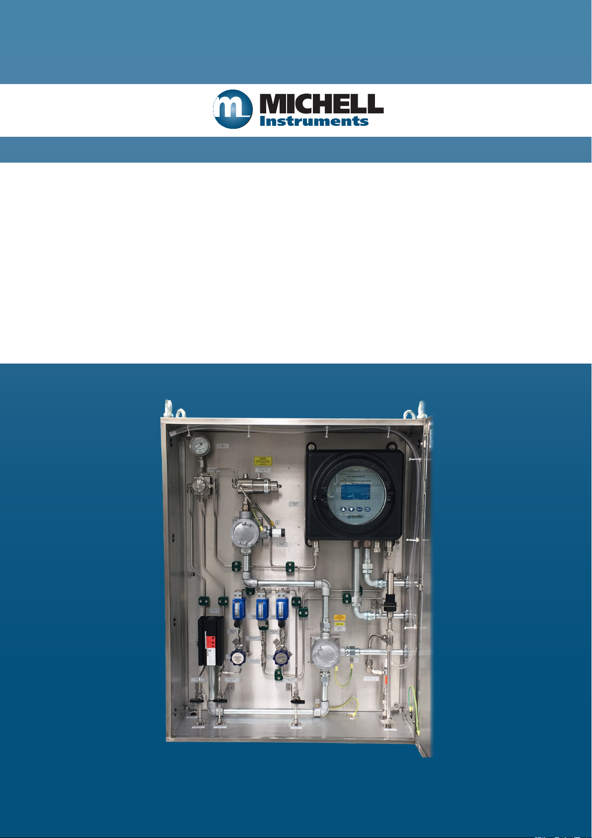
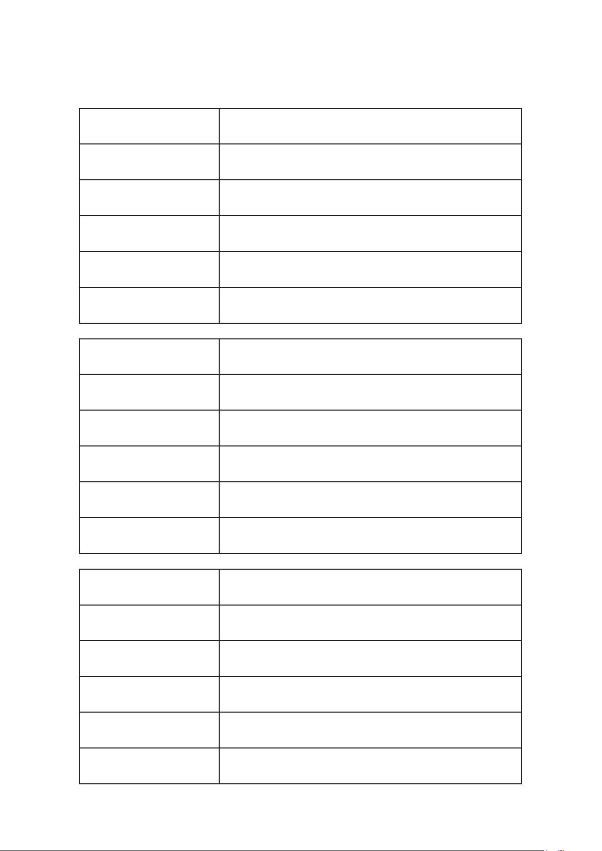
Condumax II
(Class 1 Division 1)
Hydrocarbon Dew-Point Analyzer
Sampling System
Installation, Operation & Maintenance Manual
97525, Issue 1
November 2016
Page 2
Please ll out the form(s) below for each instrument that has been purchased.
Use this information when contacting Michell Instruments for service purposes.
Instrument
Code
Serial Number
Invoice Date
Location of Instrument
Tag No
Instrument
Code
Serial Number
Invoice Date
Location of Instrument
Tag No
Instrument
Code
Serial Number
Invoice Date
Location of Instrument
Tag No
Page 3
Condumax II
For Michell Instruments' contact information please go to
www.michell.com
© 2016 Michell Instruments
This document is the property of Michell Instruments Ltd. and may not be copied or
otherwise reproduced, communicated in any way to third parties, nor stored in any Data
Processing System without the express written authorization of Michell Instruments Ltd.
Page 4

Condumax II Sampling System -
NEC Compatible IOM Manual
Contents
Safety ................................................................................................................................vi
Electrical Safety ...........................................................................................................vi
Pressure Safety ............................................................................................................vi
Toxic Materials .............................................................................................................vi
Repair and Maintenance ...............................................................................................vi
Safety Conformity ........................................................................................................vi
Abbreviations ..................................................................................................................... vii
Warnings ........................................................................................................................... vii
1 INTRODUCTION ................................................................................................1
1.1 General ............................................................................................................ 1
2 INSTALLATION ..................................................................................................4
2.1 Gas Connections ............................................................................................... 6
2.2 Power Supply Connection .................................................................................. 6
2.3 Output Wiring Connections ................................................................................ 7
3 OPERATION ......................................................................................................9
3.1 System Start-Up Procedure .............................................................................. 10
3.2 System Shut-Down Procedure .......................................................................... 11
3.3 Pressure Regulator Temperature Control ........................................................... 12
4 OPTIONS ........................................................................................................13
4.1 Enclosure Heater Temperature Control .............................................................. 13
4.2 Enclosure Cooling ........................................................................................... 13
5 MEMBRANE AND PARTICULATE FILTER ELEMENT REPLACEMENT .......................14
5.1 Service Intervals ............................................................................................. 14
5.2 Installing the Filter Element and Membrane ...................................................... 14
iv 97525, Issue 1, November
Page 5

Condumax II Sampling System -
NEC Compatible IOM Manual
Appendices
Appendix A Technical Specications ..............................................................................18
Appendix B Quality, Recycling & Warranty Information ................................................... 20
B.1 Pressure Equipment Directive (PED) 97/23/EC ..............................20
B.2 Recycling Policy .......................................................................... 20
B.3 WEEE Compliance .......................................................................20
B.4 RoHS2 Compliance ...................................................................... 21
B.5 Warranty ....................................................................................21
B.6 Reach Compliance ....................................................................... 22
B.7 Calibration Facilities ..................................................................... 22
B.8 Return Policy ..............................................................................23
B.9 Manufacturing Quality ................................................................. 23
Appendix C Analyzer Return Document & Decontamination Declaration .......................... 25
Figures
Figure 1 Condumax II Sampling System - Indoor Version ...........................................4
Figure 2 Condumax II Sampling System - Outdoor Version .........................................5
Tables
Table 1 Wire colors .................................................................................................6
Table 2 Terminal marks ...........................................................................................7
Table 3 Minimum cable requirements, power connectors ............................................7
Table 4 Wire Numbers, HC Dew-Point Version ...........................................................7
Table 5 Wire Numbers, HC and Water Dew-Point Version ...........................................8
Table 6 Minimum cable requirements, wire connectors ...............................................8
Table 7 Potentionmeter markings - CSA Version ...................................................... 12
Michell Instruments v
Page 6

Condumax II Sampling System -
NEC Compatible IOM Manual
Safety
The manufacturer has designed this equipment to be safe when operated using the procedures
detailed in this manual. The user must not use this equipment for any other purpose than that
stated. Do not apply values greater than the maximum value stated.
This manual contains operating and safety instructions, which must be followed to ensure the safe
operation and to maintain the equipment in a safe condition. The safety instructions are either
warnings or cautions issued to protect the user and the equipment from injury or damage. Use
competent personnel using good engineering practice for all procedures in this manual.
Electrical Safety
The instrument is designed to be completely safe when used with options and accessories supplied
by the manufacturer for use with the instrument. The input power supply voltage limits are 110 to
120 V AC, 60 Hz or 220 to 240 V AC, 50 Hz.
Pressure Safety
DO NOT permit pressures greater than the safe working pressure to be applied to the instrument.
The specied safe working pressure is 100 barg (1450 psig). Refer to Appendix A, Technical
Specications.
Toxic Materials
The use of hazardous materials in the construction of this instrument has been minimized. During
normal operation it is not possible for the user to come into contact with any hazardous substance
which might be employed in the construction of the instrument. Care should, however, be exercised
during maintenance and the disposal of certain parts.
Repair and Maintenance
The instrument must be maintained either by the manufacturer or an accredited service agent. Refer
to www.michell.com for details of Michell Instruments’ worldwide ofces contact information.
Safety Conformity
This product meets the essential protection requirements of the relevant EU directives.
vi 97525, Issue 1, November
Page 7
Condumax II Sampling System -
NEC Compatible IOM Manual
Abbreviations
The following abbreviations are used in this manual:
AC alternating current
barg pressure unit (=100 kP or 0.987 atm)
°C degrees Celsius
°F degrees Fahrenheit
lbs pound(s)
kg kilogram(s)
HCdp hydrocarbon dew-point
Nl/min normal liters per minute
m meter(s)
mA milliampere
max maximum
m3/hour cubic meters per hour
mm millimeters
% percentage
psig pounds per square inch
temp temperature
V Volts
W Watts
Warnings
The following general warnings listed below are applicable to this instrument. They are
repeated in the text in the appropriate locations.
Where this hazard warning symbol appears in the following
sections it is used to indicate areas where potentially hazardous
operations need to be carried out.
Where this symbol appears in the following sections it is used to
indicate areas of potential risk of electric shock.
Michell Instruments vii
Page 8

Condumax II Sampling System -
NEC Compatible IOM Manual
This page intentionally left blank
viii 97525, Issue 1, November
Page 9

Condumax II Sampling System -
NEC Compatible IOM Manual
1 INTRODUCTION
1.1 General
The Condumax II Hydrocarbon Dew-Point Analyzer Sampling System is specifically
designed for the measurement of hydrocarbon and water dew-point in natural gas.
The addition of water dew-point is optional to factory order. The system is configured
with the necessary pressure letdown and flow control required for measurement at
pressure before finally venting to an atmospheric or a low pressure flare line system.
A fast-loop bypass flow arrangement is included to reduce sample flow response time
lag and to enable the filter to be drained automatically of any potential hydrocarbon
liquids and hydrates formed. Tube and process connections are 1/4” OD.
HC dew-point analysis pressure is adjusted by a heated pressure regulator in the
range up to 35 barg (500 psig). However, it is typical for measurements to be made at
the cricondentherm condition of 27 barg (400 psig), where the highest HC dew-point
temperature will be detected on the retrograde phase envelope.
INTRODUCTION
The water dew-point (where fitted) is measured at full pipeline pressure, to determine
the highest water dew-point for the gas sample being analyzed.
The complete Condumax II Hydrocarbon Dew-Point Analyzer Sampling System can be
located close to the gas sample take-off point in a potentially explosive environment
- designated Class 1 Division 1 hazardous area.
The indoor version Sampling System gas handling components are assembled on
a stainless steel plate suitable for wall mounting within a temperature controlled
analyzer house.
The outdoor version Sampling System is housed within a stainless steel enclosure (304
or 316) for direct field installation next to the process line (with overall environmental
protection to IP66).
The Sampling System must be located in a constant temperature controlled environment
of at least +10°C (+18°F) above the highest envisaged dew-point temperature.
All sample gas wetted metallic parts are in AISI 316L stainless steel with Viton® soft
parts that comply with the NACE standard MR-01-75 (latest edition). Tube fittings are
twin ferrule compression type. All gas and cable entries are located in the base of the
enclosure.
The sample flow gas handling components are as follows:
• Gas Inlet Isolation Valve (BV1):
Allows user to manually isolate the system from the process sample gas
supply line for maintenance or servicing.
• Coalescing & Membrane Filter (F1):
Provides system protection from contamination of liquid carry-over of
hydrocarbon / glycol mist particles using membrane ltration.
Michell Instruments 1
Page 10

INTRODUCTION
• Line Pressure Gauge (PG1):
Indicates the sample gas line pressure.
• HCdp Pressure Regulator (PR1):
Allows the user to manually set the sample gas analysis pressure for
hydrocarbon dew-point measurement.
• HC and H2O Dew-Point Analyzer (Condumax II):
Provides measurement and output of hydrocarbon & water dew point of the
sample gas.
• Non Return Valve (NRV1):
Provides system protection from back pressure of vent gas when sample gas
is not owing.
Condumax II Sampling System -
NEC Compatible IOM Manual
• HCdp Flow Metering Valve (FV1):
Allows the user to manually set the sample gas ow rate across the
hydrocarbon dew-point sensor.
• HCdp Flowmeter (FM1):
Provides indication of the sample gas ow rate across the hydrocarbon dewpoint sensor.
• H2Odp Letdown Pressure Regulator (PR3) {if tted}:
Provides pressure letdown from line pressure to a lower vent pressure.
• Non Return Valve (NRV3) {if tted}:
Provides system protection from back pressure of vent gas when sample gas
is not owing.
• H2Odp Flowmeter/Metering Valve (FM3) {if tted}:
Allows the user to manually set and provide indication of the sample gas
owrate across the water dew-point sensor.
• Gas Outlet Isolation Valve (BV2):
Allows the user to manually isolate the system from the gas outlet line for
maintenance or servicing.
2 97525, Issue 1, November
Page 11

Condumax II Sampling System -
NEC Compatible IOM Manual
The bypass ow gas handling components are as follows:
• Bypass Flow Letdown Pressure Regulator (PR2):
Provides pressure letdown from sample line pressure to a lower vent pressure.
• Non Return Valve (NRV2):
Provides system protection from back pressure of vent gas when sample gas
is not owing.
• Bypass Flowmeter & Valve (FM2):
Allows the user to manually set and provide indication of the bypass gas ow
rate across the membrane lter.
• Letdown Gas Vent Isolation Valve (BV3):
INTRODUCTION
Allows the user to manually letdown the sample gas pressure trapped in the
system for maintenance or servicing.
Michell Instruments 3
Page 12

INSTALLATION
2 INSTALLATION
The Condumax II Hydrocarbon Dew-point Analyzer Sampling System gas handling
components are assembled onto a stainless steel mounting plate suitable for wall
mounting.
The indoor version Sampling System should be located in a constant temperature
controlled environment of at least +10°C (+18°F) above the highest envisaged dewpoint
temperature at a point as close to the sample gas take-off point as possible. This
will minimize sample line response time lag in a designated IEC Zone 1 and Zone 2
hazardous area and NEC Class 1, Group B (for CSA Version Sampling System).
The outdoor version Sampling System provides environmental ingress protection to IP66
and should be mounted vertically, free of any appreciable vibration, in a permanently
shaded position to prevent heating effects through sun radiation. The Sampling System
enclosure has thermostatically controlled heating (xed set point, optional adjustable).
Enclosure cooling, using a compressed-air-driven vortex tube and adjustable thermostat,
is recommended for installation in hot climates.
Condumax II Sampling System -
NEC Compatible IOM Manual
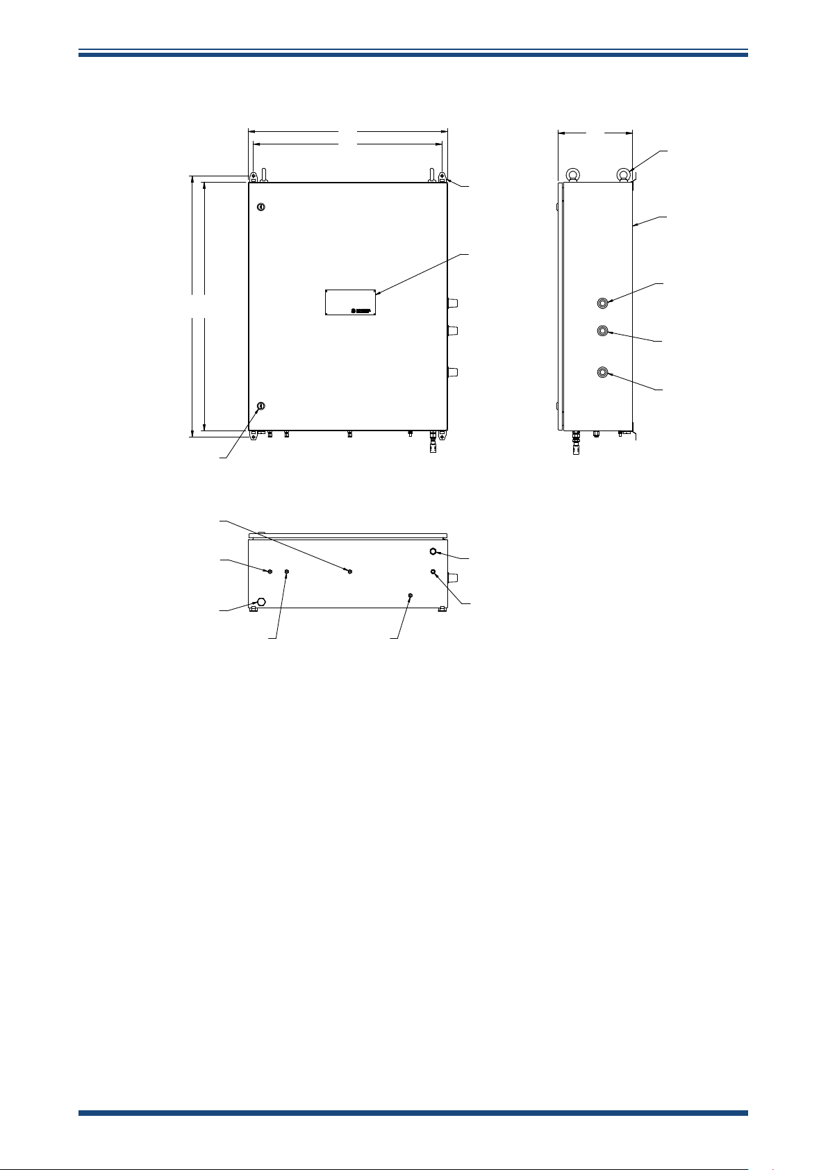
GAS INTLET CONNECTION
6mm/1/4" OD TUBE FITTING
GAS OUTLET CONNECTION
6mm/1/4" OD TUBE FITTING
750mm 30"
700mm 28"
970mm 38"
938mm 37"
EARTH BONDING
CONNECTION
LET DOWN GAS VENT
6mm/1/4" OD TUBE FITTING
CONDUIT ENTRY (1/2" NPT)
FOR OUTPUT CABLE
CONDUIT ENTRY (1/2" NPT)
FOR SUPPLY CABLE
316SS MOUNTING
PLATE
MOUNTING HOLES
O
8MM (5/16")
250mm 10" 13m m 1"
Figure 1
Condumax II Sampling System - Indoor Version
4 97525, Issue 1, November
Page 13
Condumax II Sampling System -
NEC Compatible IOM Manual
INSTALLATION
1050
DOUBLE BIT
LOCKS (3mm)
SAMPLE GAS OUTLET
(1/4" OD TUBE)
800
758
316SS MOUNTING
BRACKETS
(
O
10mm HOLES)
316SS ENGRAVED
NAME/TAG PLATE
MODEL: CONDUMAX II
TYPE: HC DEW POINT ANALYZER
SERIAL NUMBE R : nnnnnn /201 6
TAG NUMBER :
1000
www.michell.com
300
GALVANISED STEEL
LIFTING EYE BOLTS
316SS, IP66,
INSULATED
ENCLOSURE
ANALYZER
POWER INLET
(1/2" HUB)
ANALYZER
SIGNAL OUT PUTS
(1/2" HUB)
HEATING
POWER INL ET
(1/2" HUB)
SAMPLE GAS INLET
(1/4" OD TUB E)
BREATHER/DRAIN
LETDOW N GAS VENT /DRAIN
(1/4" OD TUBE )
Figure 2
WARM AI R VENT
VIA SILENCER
INSTRUMENT AIR INLET
(1/4" NPTF)
EARTHING
POST (M8)
Condumax II Sampling System - Outdoor Version
Michell Instruments 5
Page 14
INSTALLATION
2.1 Gas Connections
Ensure that the process sample gas supply line is well ushed
Connections are as follows:
1. Sample Gas Inlet
¼” OD Swagelok® tube tting
(100 narg (1450 psig) maximum supply pressure)
2. Sample Gas Outlet
¼” OD Swagelok® tube tting
(Vent to atmosphere/low pressure are. 7 barg (101 psig) maximum back
pressure)
Condumax II Sampling System -
NEC Compatible IOM Manual
through to clear any liquids and debris present, prior to
connection to the Sampling System.
3. Letdown Gas Vent
¼” OD Swagelok® tube tting (NEC version)
(Vent to atmosphere)
NOTE: All tube tting connections are made directly onto the isolation ball
valves.
2.2 Power Supply Connection
A single-phase AC mains power supply is required to operate the Sampling System.
The factory-set power supply voltage is indicated on a yellow label located on the rear
panel. NOTE: The user cannot change the specied power supply voltage.
The Condumax II analyzer is powered via the mains from the analyzer conduit.
Wire Color Power Connection
Brown Line Voltage
Blue Neutral
Green/Yellow Earth
Table 1 Wire colors
6 97525, Issue 1, November
Page 15

Condumax II Sampling System -
NEC Compatible IOM Manual
Wiring connections, for power to heater circuit and heated regulator are made onto
terminals within the Power Circuits conduit box.
Terminals are marked:
Terminal No. Power Connection
1 Line Voltage
4 Neutral
Table 2 Terminal marks
NOTE: A ground/earth stud is provided in the base of the enclosure. This
must be used to earth bond the Sampling System.
INSTALLATION
Ground / Earth
A local power isolator switch MUST BE provided on the Power Circuit to the Condumax
II Hydrocarbon Dew-Point Analyzer for maintenance or servicing. Note: This switch
only isolates power to the analyser NOT any other circuits.
Minimum Cable Requirements
Power Cable 3 core, 0.75mm2 conductor area (6A)
Table 3 Minimum cable requirements, power connectors
2.3 Output Wiring Connections
Two analog 4-20 mA outputs and a Modbus RS485 digital interface are available.
Connections are made onto wires from the Outputs conduit.
Wires are marked:
Wire No. Output
1 Modbus RS485 digital comms Earth
2 Modbus RS485 digital comms A
3 Modbus RS485 digital comms B
4 Pressure measurement current - mA2
5 Pressure measurement current + mA2
6 Hydrocarbon dew-point measurement current - mA1
7 Hydrocarbon dew-point measurement current +mA1
Table 4 Wire Numbers, HC Dew-Point Version
HC Dew-Point Version
Michell Instruments 7
Page 16

INSTALLATION
Recommended Minimum Cable Requirements
Condumax II Sampling System -
NEC Compatible IOM Manual
HC and Water Dew-Point Version
Wire No. Output
1 Modbus RS485 digital comms Earth
2 Modbus RS485 digital comms A
3 Modbus RS485 digital comms B
4 Water dew-point measurement current - mA1
5 Water dew-point measurement current + mA1
6 Hydrocarbon dew-point measurement current - mA1
7 Hydrocarbon dew-point measurement current + mA1
Table 5 Wire Numbers, HC and Water Dew-Point Version
Communications Cable
Communications Cable
Table 6 Minimum cable requirements, wire connectors
For use with 4-20mA only or Modbus only
1 pair individually and overall screened, 0.5mm2 conductors
For use with 4-20mA and Modbus
2 pair individually and overall screened, 0.5mm2 conductors
8 97525, Issue 1, November
Page 17

Condumax II Sampling System -
NEC Compatible IOM Manual
3 OPERATION
Operation of the Condumax II Sampling System should be carried out in conjunction
with, and referring to, the Condumax II Hydrocarbon Dew-Point Analyzer User Manual
prior to commencing the System Start-Up Procedure (Section 3.1).
Before commencing the start-up procedure it is essential to ensure that the installation
conforms to the correct hazardous area and local plant standards.
Before any gas pressure is applied, check that all gas inlet & outlet connections are fully
tightened up and that all valves and regulators are in the closed position.
Additionally, for the outdoor version, the heater/thermostat circuit will need to achieve
the set-point temperature.
OPERATION
BEFORE power is applied to the Sampling System check that the
Condumax II Power Isolator switch is set to the
Apply power to the Sampling System and allow the pressure regulator temperature
to stabilize. This will prevent the possibility of condensation occurring within the gas
handling components during start-up.
There is a mandatory purge procedure stipulated as part of the
certication of the Condumax II product. This procedure must
be fully carried out prior to any power or signal connections to
the Condumax II being energized.
This procedure must also be carried out at any time following
service or maintenance periods that cause any of the Condumax
II or associated gas handling equipment sample lines to be
disconnected.
It is not necessary to carry out this procedure of, during a shut
down period, the sample lines have not been disconnected or of
the power or signal connections only have been connected.
OFF position.
Before commencement of the start-up procedure ensure that
all power and signal connections to the Condumax II are fully
isolated and if necessary observe the stipulated de-energization
period of 45 minutes.
Michell Instruments 9
Page 18

OPERATION
3.1 System Start-Up Procedure
Proceed as follows:
1. Unscrew and remove the Condumax II ameproof enclosure cover after
rst loosening the hex grub screw.
2. The user interface/display assembly uses two ¼-turn bayonet style fasteners
to secure it and are nger operated - clockwise to lock, counter-clockwise
to release. Temporarily, the user interface/display once disconnected from
the two ¼-turn fasteners, can be re-positioned on the instrument by
securing the right-hand fastener in the left-hand fastener position. This
will situate the user interface/display assembly in an overhanging position
outside of the enclosure, allowing greater access. If there is insufcient
space to accommodate the overhanging user interface/display assembly
on the left-hand side then it can be fully disconnected from the instrument
by disconnecting the ribbon cable connection to the main processor PCB.
3. Locate the solenoid valve and the manual override operating adjuster
(brass screw handle) mounted on the base of the solenoid valve body.
Condumax II Sampling System -
NEC Compatible IOM Manual
4. Adjust the solenoid valve to the PURGE POSITION (fully screwed in
clockwise) as shown on the label attached to the solenoid valve.
5. Ensure the Letdown Gas Vent Isolation Valve (BV3) is CLOSED.
6. OPEN the Gas Outlet Isolation Valve (BV2).
7. Slowly OPEN the Gas Inlet Isolation Valve (BV1) to allow sample gas to
enter the Sampling System.
8. Fully OPEN the Bypass Flow Letdown Pressure Regulator (PR2).
9. Adjust the Bypass Flow Flowmeter/Metering Valve (FM2) to indicate a gas
ow rate of approximately 0.4m³/hour (6.7 Nl/min) (full-scale).
10. Slowly OPEN the HCdp Pressure Regulator (PR1) to provide a purge ow
through the Condumax II (2 full turns).
11. Adjust the HCdp Flow Metering Valve (FV1) to indicate a sample gas ow
rate of approximately 0.12m³/hour (2 Nl/min) (full-scale) on the HCdp
Flowmeter (FM1).
12. Fully OPEN the H2Odp Letdown Pressure Regulator (PR3) {if tted}.
13. Adjust the H2Odp Flowmeter/Metering Valve (FM3) {if tted} to indicate a
sample gas owrate of approximately 0.2 to 0.3m3/hour (3.3 to 5 Nl/min)
mid to three-quarters full scale).
14. Allow the sample gas to purge the system for a minimum period of 3
minutes.
15. Re-adjust the solenoid valve to the Normal Operating Position (fully
unscrewed counter-clockwise) as shown on the label attached to the
solenoid valve.
16. Re-t the Condumax II user interface/display assembly and ameproof
enclosure cover.
10 97525, Issue 1, November
Page 19

Condumax II Sampling System -
NEC Compatible IOM Manual
17. After the ameproof enclosure cover has been retted the Condumax II is
ready for power up.
18. Switch on the power to the Condumax II using the Condumax II Power
Isolator switch located on the Power Circuits junction box.
19. Re-adjust the HCdp Pressure Regulator (PR1) to set the HCdp gas analysis
pressure. Pressure is indicated on the main display of the Condumax II.
It is normal practice for an analysis pressure of 391 psig (27 barg) to
be set for the analysis of hydrocarbon dew point, as it is the recognized
cricondentherm condition (pressure at which the highest hydrocarbon
dew-point temperature will exist).
NOTE: The water dew-point gas analysis pressure is set at full
line pressure and has no adjustment.
20. Re-adjust the hydrocarbon dew-point sample gas ow rate to approximately
0.06m³/hour (1 Nl/min) using the HCdp Flow Metering Valve (FV1).
21. Re-adjust the water dew-point sample gas owrate to approximately
0.2m3/hour (3.3 Nl/min) using the H2Odp Flowmeter/Metering Valve (FM3)
{if tted}.
OPERATION
22. Re-adjust the bypass ow rate to approximately 0.4m³/hour (6.6 Nl/min)
using the Bypass Flow Flowmeter/Metering Valve (FM2).
23. Close the cabinet door and allow the temperature to stabilize for at least
one hour before monitoring a measurement.
Refer to the Condumax II Hydrocarbon Dew-Point Analyzer User’s Manual for further
operating instructions.
3.2 System Shut-Down Procedure
There is a mandatory de-energization time period of 45 minutes
stipulated in the certication of the Condumax II product. This
special condition must be fully carried out prior to removing the
cover of the Condumax II ameproof enclosure.
Proceed as follows:
1. Isolate the Sampling System from the sample gas supply line by CLOSING
the Gas Inlet Isolation Valve (BV1).
2. Allow a short time for the Sampling System to vent/depressurize before
attempting to carry out any work on the system.
3. Depressurize the Sampling System by CLOSING the Gas Outlet Isolation
Valve (BV2) and OPENING the Letdown Gas Vent Isolation Valve (BV3).
4. Ensure the Condumax II Power Isolator switch is in the OFF position.
5. After power down a minimum period of 45 minutes must be observed
before removing the cover of the Condumax II.
Michell Instruments 11
Page 20

OPERATION
3.3 Pressure Regulator Temperature Control
WARNING
This operation will expose electrical parts operating at high
voltage. Therefore, isolate the power supply from the Sampling
System before making adjustments.
The heated pressure regulator contains an adjustment for the temperature control
set point (factory-set to approximately +40°C (+104°F)). It may need adjustment to
increase/decrease the heat requirements to the regulator dependent on the high/low
inlet gas pressure.
This can be identied by the manufacturer markings:
CSA version GO HPR-2 markings
Condumax II Sampling System -
NEC Compatible IOM Manual
CSA Version - GO HPR-2 Pressure Regulator
To adjust the setting proceed as follows:
1. Unscrew and remove the cover of the junction box after rst loosening the
hex grub screw.
2. Adjust the heater output by turning the potentiometer clockwise to increase
and anti-clockwise to decrease.
3. The seven markings around the potentiometer equate to an approximate
temperature value for the heater of:
1 = +75°F (+24°C) Recommended setting
2 = +80°F (+27°C)
3 = +85°F (+29°C)
4 = +95°F (+35°C)
5 = +110°F (+43°C)
6 = +130°F (+54°C)
7 = +175°F (+79°C)
Table 7 Potentionmeter markings - CSA Version
Other settings may be advised by Michell
Instruments, dependent upon application
Should not be set
4. Screw back the junction box cover and tighten the hex grub screw.
12 97525, Issue 1, November
Page 21

Condumax II Sampling System -
NEC Compatible IOM Manual
4 OPTIONS
4.1 Enclosure Heater Temperature Control
Sampling systems can be tted with temperature control, to maintain a constant
temperature environment of at least 10°C (18°F) above the highest envisaged dewpoint temperature, independent of surrounding temperature variations. The temperature
control system, consists of a heater controlled by a xed preset thermostat to provide
internal ambient air temperature control of >+15°C (>+59°F) or >+35°C (>+95°F).
4.2 Enclosure Cooling
A sampling system enclosure cooling kit can be tted to the stainless steel enclosure.
The cooling device is a Vortex tube driven by instrument grade (liquid and particulatefree) compressed air. A mechanical thermostat controls the air ow through the vortex
tube and is factory set, to maintain an internal ambient <+40°C (104°F). A manifold
(clear plastic pipe) positioned around the internal walls of the enclosure distributes the
cooling air throughout.
OPTIONS
Michell Instruments 13
Page 22

MAINTENANCE
Condumax II Sampling System -
NEC Compatible IOM Manual
5 MEMBRANE AND PARTICULATE FILTER ELEMENT REPLACEMENT
5.1 Service Intervals
The life expectancy of the lter elements is dependent upon operating conditions in
each specic application. As a minimum it is recommended that the lter elements
be changed every 12 months. If inspection of a removed element shows that it is in
poor/good condition after 12 months of operation then the operating period between
replacements may be reduced/increased accordingly.
The disposable microber lter element cannot be cleaned as the solids are trapped
within the depth of the element not on the surface. Also ensure that all O-rings are
changed at regular intervals, preferably at the same time as the lter elements.
5.2 Installing the Filter Element and Membrane
Warning
The lter housing is a pressure vessel; it must never be used
above its stated maximum allowable working pressure and
must be used within its stated temperature range. Ensure that
these items are used in well-designed piping systems with
suitable indicators to warn users and servicing personnel of the
presence of pressure and high temperatures. Wherever possible
use pressure limiting or saftey devices. Remember that the
pressure rating os reduced at high temperatures. Consult Michell
Instruments for guidance.
It is the responsibility of the user to ensure that the materials
of construction of the lter housing, gasket and lter media are
suitable for the intended application. During every servicing, a
visual inspection must be made of the surfaces of the housing
for signs of corrosion, erosion or general wear. The housing
must be removed from service if any of these signs are evident
as there are no corrosion allowances used used in the design of
these lters. It is not recommended that these lters be used on
unstable uids.
The following items have not been taken into account during the design of the lter
housing:
1. Static pressure and mass of contents
2. Trafc, wind and earthquake loading
3. Reaction forces and moments resulting from mounting
4. Corrosion, erosion and fatigue
5. Decomposition of unstable uids
6. External re
14 97525, Issue 1, November
Page 23

Condumax II Sampling System -
1
2
3
4
NEC Compatible IOM Manual
Installing the Filter Housing
As the lter housing is a pressure vessel the system connections and accessory outlets
must be leak tight. It is good practice to use a pipe sealant on the ttings prior to
connecting to the lter housing ports. This will allow disassembly at a later time, if
required. Any sealant such as PTFE tape, paste or other compound may be used if
compatible with the ltered media. The torque value of the ttings will depend upon
the quality of the ttings and the type of sealant used but should typically be between
40Nm and 75Nm. Ensure the ttings get inspected during servicing and re-tightened if
necessary. It is not recommended that heads and bowls from different lter assemblies
are swapped.
When installing lter housing and elements care should be taken to ensure the head
and bowls are kept as a pair. It is not recommended that heads and bowls from different
lter assemblies be swapped.
Wherever possible, installation of lter housings should be made using an appropriate
mounting bracket to avoid excessive loads on the piping.
MAINTENANCE
Changing the Filter Element
Ensure there is no pressure in the housing. Remove the bowl, element retainer and lter
element.
The disposable coalescing lter element is sealed by compression against a at surface.
Gaskets are not required between the lter element and components of the housing.
The element is located by guides which t the inside diameter of the tube at each end.
The element is sealed by tightening a threaded element retainer.
Before replacing the housing bowl ensure that the mating threads and
sealing faces are clean and damage free. It is recommended that the
threads and sealing faces are lubricated with a small amount of silicone
grease before assembly. In the case of ‘S’ type stainless steel housings
tted with a solid PTFE gasket the bowl should be tightened to a torque
of between 30Nm and 40Nm.
Michell Instruments 15
Page 24

MAINTENANCE
Membrane Replacement
The membrane is held in place by the O-ring.The whole membrane holder unit comes
free from the housing leaving the lter housing /body still intact with the process lines
with no need to loosen connections. The membrane can then be replaced on a work
bench using a round nose pair of tweezers - the old O-ring is removed with the old
membrane. The sintered disc should be removed and cleaned or replaced. Drag a new
membrane over the sintered disc carefully as not to cause damage, until centralized
over the sintered disc and O-ring groove. Place the new O-ring over/around the new
membrane and gently push into the O-ring groove. Replace the coalescing lter element
where applicable with a new element and screw/locate the whole membrane holder
back into the lter housing/body. The inlet is stamped no.1 and the outlet is stamped
no.2, the other two ports are drain ports. Both can be used or one drain may be blanked
off with a plug.
Service Intervals
A disposable microber lter element continues to lter at its original efciency as long
as it is kept in service. The life of the element is determined by the increase in ow
resistance caused by trapped solids in the element. The element should be changed
when the ow falls below an acceptable level, or the pressure drop becomes too high.
In any case the element should be replaced before the pressure drop across it reaches
0.7 bar. The disposable microber lter elements cannot be cleaned as the solids are
trapped within the depth of the element, not on the surface.
Condumax II Sampling System -
NEC Compatible IOM Manual
Ensure that gaskets are changed at suitable intervals. The interval time will depend on
service and operating conditions, but it should be at least every three months.
16 97525, Issue 1, November
Page 25

Condumax II Sampling System -
NEC Compatible IOM Manual
APPENDIX A
Appendix A
Technical Specications
Michell Instruments 17
Page 26

APPENDIX A
Condumax II Sampling System -
NEC Compatible IOM Manual
Appendix A Technical Specications
General
Gas Wetted Materials 316L stainless steel with Viton® soft parts
Sample Gas Hydrocarbon/Natural Gas
Sample Gas Pressure 10 to 100 barg (145 to 1450 psig)
HCdp range = 0.02 to 0.13 m³/hour (0.3 to 2.2 Nl/min)
Sample Gas Flow rate
Bypass Gas Flow Rate
Filters Coalescing & membrane lter
Enclosure
Sample Gas Connections ¼” OD Swagelok® twin ferrule tube ttings
Cable Entries Conduit with individual wires
Power Supply 110 to 120 V AC 60 Hz
Power Consumption 400 W max
Operating Temperature
Weight 75kg (165lbs) max
(nominal setting = 0.06 m³/hour (1 Nl/min))
H2Odp range = 0.04 to 0.4 m³/hour (0.6 to 6.6 Nl/min)
(nominal setting = 0.2 m³/hour (3.3 Nl/min))
Range = 0.04 to 0.4 m³/hour (0.6 to 6.6 Nl/min)
(nominal setting = 0.2 m³/hour (3.3 Nl/min))
304/316 stainless steel tted with wall-mounting brackets
(Ingress protection rated to IP66)
-20 to +60°C (-4 to +140°F) <95%RH
(+40°C (+104°F) max continuous operation)
Optional
Compressed air via Vortex tube controlled by a mechanical
Enclosure Cooling
(Optional)
Enclosure Heating 100 W Heater with fixed preset +20ºC or +40ºC set-point thermostat
thermostat. Maximum cooling capacity = 410W @ internal temp
of +35°C (+95°F) and external temp of +55°C (+131°F) with
maximum air input temp of +40°C (+104°F)
18 97525, Issue 1, November
Page 27

Condumax II Sampling System -
NEC Compatible IOM Manual
APPENDIX B
Appendix B
Quality, Recycling
& Warranty
Information
Michell Instruments 19
Page 28

APPENDIX B
Condumax II Sampling System -
NEC Compatible IOM Manual
Appendix B Quality, Recycling & Warranty Information
B.1 Pressure Equipment Directive (PED) 97/23/EC
The above Directive has been implemented in United Kingdom Law by the Pressure
Equipment Regulations 1999.
The Regulations require that all pressure equipment and assemblies within the scope of
the Pressure Equipment Directive must be safe when placed on the market or put into
service.
Michell Instruments’ products have been assessed and, as referenced against the
Classication Charts detailed in Annex II of the Directive, do not fall into the requirements
for CE marking compliance with the Pressure Equipment Directive.
Article 3, paragraph 3 states that any product containing a pressurized uid that does
not qualify for compliance should, nevertheless, be constructed with Sound Engineering
Practice (SEP).
Michell Instruments attests here that its products have been designed, manufactured &
tested to assure safe operation, and in accordance with Sound Engineering Practices.
B.2 Recycling Policy
Michell Instruments is concerned with the protection of the environment. It is our
commitment to reduce and eliminate from our operations, wherever possible, the use
of substances which may be harmful to the environment. Similarly, we are increasingly
using recyclable and/or recycled material in our business and products wherever it is
practical to do so.
To protect natural resources and to promote material reuse, please separate batteries
from other types of waste and recycle responsibly. If batteries are not properly disposed
of, these substances can cause harm to human health and the environment.
The product that you have purchased may contain recyclable and/or recycled parts and
we will be happy to provide you with information on these components if required. For
further information please see the following sections.
B.3 WEEE Compliance
Directive 2012/19/EU 4 July 2012 on Waste Electronic and Electrical Equipment (WEEE)
The Waste Electronic and Electrical Equipment (WEEE) Directive places rules upon
European manufacturers of electrical and electronic equipment. The directives’ aim is
to reduce the impact that electronic devices have on the environment.
Michell Instruments is in full compliance with the WEEE Directive and is registered with
an approved recycler (Registration No. WEE/JB0235YW) and treats the requirement of
the directive and the protection of the environment with the utmost importance. All
Michell Instruments’ products are appropriately marked indicating their requirement for
recycling.
It may be required to return certain instruments for treatment at the end of their
working life.
Feb 2013
20 97525, Issue 1, November
Page 29

Condumax II Sampling System -
NEC Compatible IOM Manual
B.4 RoHS2 Compliance
Directive 2011/65/EU of the European Parliament and of the Council of 8 June 2011
The Restriction of Hazardous Substances (RoHS) Directive places rules upon European
manufacturers of electrical and electronic equipment. The directives’ aim is to reduce
the impact that electronic devices have on the environment.
According to the EC Directive 2002/95/EC, Michell Instruments’ products qualify as
Category 9, Control and Monitoring Equipment. Under the 2002/95/EC Directive,
Category 9 products are exempt from compliance with the Directive.
However, the careful design of all Michell Instruments’ products takes into consideration
the requirements of the Directive and, wherever possible, compliance is achieved. All
future products will be developed entirely using compliant materials. Furthermore,
Michell Instruments is taking active steps to remove non-compliant materials and
components from existing products wherever these may occur. Presently, none of the
non-compliant materials are known to occur in Michell Instruments’ products.
APPENDIX B
The new Directive 2011/65/EU (RoHS2) entered into force on 21 July 2011 and required
all Member States to transpose the provisions into their respective national laws by 2
January 2013.
Under the provisions of the RoHS2 EU Directive 2011/65/EU (Article 3, [24]) denes
‘Control and Monitoring Equipment’ specically as ‘monitoring and control instruments
designed exclusively for industrial or professional use’.
RoHS2 EU Directive 2011/65/EU states the closing date for compliance of any Control
and Monitoring Equipment product sold into the EU market place as 22nd July 2017.
However, the careful design policy of all Michell Instruments’ products continues to
attain compliance in the shortest practical timescales and strives to ensure that less than
0.1% of total mass per product, of all non-compliant materials, appear within them.
Michell Instruments continues to monitor suppliers and material sources to ensure that
compliance of goods provided is maintained.
January 2013
B.5 Warranty
Unless otherwise agreed, the Supplier warrants that, as from the date of delivery for
a period of 12 months, the goods and all their component parts, where applicable, are
free from any defects in design, workmanship, construction or materials.
The Supplier warrants that the services undertaken shall be performed using reasonable
skill and care, and be of a quality conforming to generally accepted industry standards
and practices.
Except as expressly stated, all warranties whether express or implied, by operation
of law or otherwise, are hereby excluded in relation to the goods and services to be
provided by the Supplier.
All warranty services are provided on a return to base basis. Any transportation costs
for the return of a warranty claim shall reside with the Customer.owner’s approval to
proceed, the product will be repaired and returned.
Michell Instruments 21
Page 30

APPENDIX B
B.6 Reach Compliance
Regulation (EC) No. 1907/2006
Registration, Evaluation, Authorisation and Restriction of Chemicals (REACH)
Michell Instruments is a manufacturer of moisture measurement and gas analysis
instrumentation and is a ‘downstream’ user of chemicals, as described by the EU Council
Directive 76/769/EEC. The products we supply are not raw chemical products (goods).
Under normal and reasonably foreseeable circumstances of application, the goods
supplied to you shall not contain or release any prohibited chemicals. No listed SVHC
(Substances of Very High Concern) appear within products manufactured by Michell
Instruments. Therefore the 0.1% mass per product, or total usage of 1 tonne/year,
will never be exceeded. For these reasons we are neither required by obligation for
registration nor for the creation of material safety data sheets (MSDS) for our products.
Our continued review of the SVHC Candidate List and latest additions is to ensure we
remain compliant.
Condumax II Sampling System -
NEC Compatible IOM Manual
Michell Instruments maintains a hazardous material register in which MSDS data sheets
are collated, and we will check that our suppliers will comply to REACH requirements for
all materials and substances we use in the processes of our manufacturing.
In the unlikely event that any chemicals of concern appear in our products in quantities
greater than 0.1% of total mass per product we will immediately inform you by
correspondence according to the REACH Article 33 requirements. Our current appraisal
is, however, that we do not expect or foresee such an incidence.
January 2013
B.7 Calibration Facilities
Michell Instruments’ calibration facilities are among the most sophisticated in the world
and have been recognized for their excellence.
Traceability to the National Physical Laboratory (NPL) UK is achieved through our UKAS
Accreditation (Number 0179). This covers dew point over the range -90 to +90°C (-130
to +194°F) and also Relative Humidity.
Dew-point calibrations are also traceable to the National Institute for Standards &
Technology (NIST) USA over the range -75 to +20°C (-103 to +68°F).
NOTE: Standard traceable calibration certicates for instruments and sensors
are not issued under our UKAS accreditation. UKAS certicates are usually to
special order and are clearly identied.
22 97525, Issue 1, November
Page 31

Condumax II Sampling System -
NEC Compatible IOM Manual
B.8 Return Policy
If a Michell Instruments’ product malfunctions within the warranty period, the following
procedure must be completed:
1. Notify a Michell Instruments’ distributor, giving full details of the problem,
the model variant and the serial number of the product.
2. If the nature of the problem indicates the need for factory service then the
instrument should be returned to Michell Instruments, carriage prepaid,
preferably in the original packaging, with a full description of the fault
and the customer contact information.
3. Upon receipt, Michell Instruments will evaluate the product to determine
the cause of the malfunction. Then, one of the following courses of action
will be taken:
• If the fault is covered under the terms of the warranty, the
instrument will be repaired at no cost to the owner and returned.
APPENDIX B
• If Michell Instruments determines that the fault is not covered
under the terms of the warranty, or if the warranty has expired,
an estimate for the cost of the repairs, at standard rates, will be
provided. Upon receipt of the owner’s approval to proceed, the
product will be repaired and returned.
B.9 Manufacturing Quality
Michell Instruments is registered with the British Standards Institute for Quality
Assurance to:
BS EN ISO 9001: 2008
Rigorous procedures are performed at every stage of production to ensure that the
materials of construction, manufacturing, calibration and nal test procedures meet the
requirements laid down by our BSI approved Quality System.
Please contact Michell Instruments (www.michell.com) if the product does not arrive in
perfect working order.
Michell Instruments 23
Page 32

APPENDIX L
Condumax II Sampling System -
NEC Compatible IOM Manual
Appendix C
Analyzer Return Document
&
Decontamination Declaration
24 97525, Issue 1, November
Page 33

Condumax II Sampling System -
APPENDIX L
NEC Compatible IOM Manual
Appendix C Analyzer Return Document & Decontamination Declaration
Decontamination Certicate
IMPORTANT NOTE: Please complete this form prior to this instrument, or any components, leaving your
site and being returned to us, or, where applicable, prior to any work being carried out by a Michell
engineer at your site.
Instrument Serial Number
Warranty Repair? YES NO Original PO #
Company Name Contact Name
Address
Telephone # E-mail address
Reason for Return /Description of Fault:
Has this equipment been exposed (internally or externally) to any of the following?
Please circle (YES/NO) as applicable and provide details below
Biohazards YES NO
Biological agents YES NO
Hazardous chemicals YES NO
Radioactive substances YES NO
Other hazards YES NO
Please provide details of any hazardous materials used with this equipment as indicated above (use continuation sheet
if necessary)
Your method of cleaning/decontamination
Has the equipment been cleaned and decontaminated? YES NOT NECESSARY
Michell Instruments will not accept instruments that have been exposed to toxins, radio-activity or bio-hazardous
materials. For most applications involving solvents, acidic, basic, ammable or toxic gases a simple purge with dry
gas (dew point <-30°C) over 24 hours should be sufcient to decontaminate the unit prior to return.
Work will not be carried out on any unit that does not have a completed decontamination declaration.
Decontamination Declaration
I declare that the information above is true and complete to the best of my knowledge, and it is safe for Michell
personnel to service or repair the returned instrument.
Name (Print) Position
Signature Date
F0121, Issue 2, December 2011
Michell Instruments 25
Page 34

http://www.michell.com
 Loading...