

Page 1

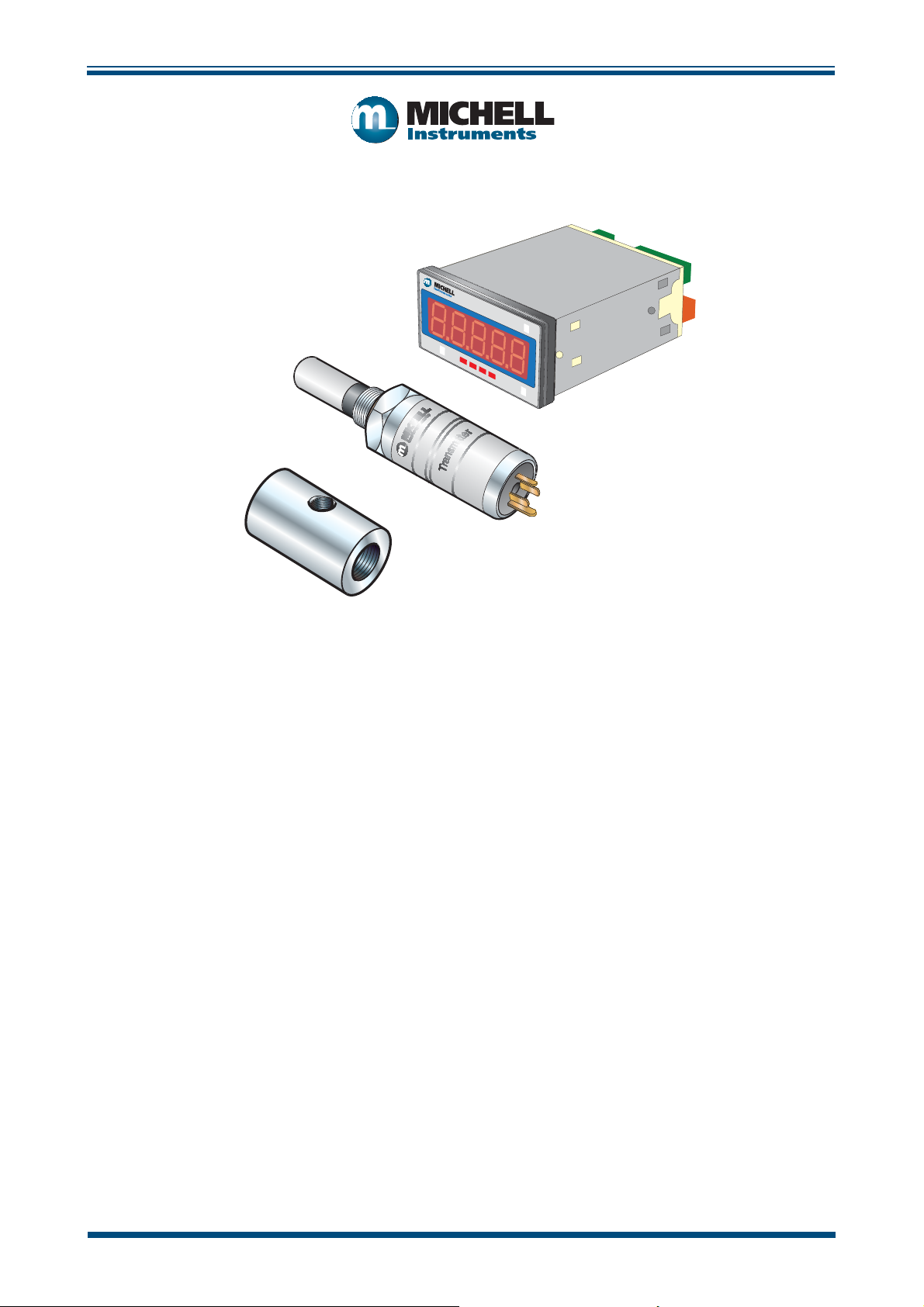
Cermet II
Hygrometer
User’s Manual
°Cdp
°Fdp
Setup
97049 Issue 25.3
October 2016
Cermet II
Advanced Online
©
ª
Page 2

Please fi ll out the form(s) below for each instrument that has been purchased.
Use this information when contacting Michell Instruments for service purposes.
Instrument
Code
Serial Number
Invoice Date
Location of Instrument
Tag No
Instrument
Code
Serial Number
Invoice Date
Location of Instrument
Tag No
Instrument
Code
Serial Number
Invoice Date
Location of Instrument
Tag No
Page 3
°Cdp
°Fdp
Setup
Cermet II
Advanced Online
Cermet II
©
ª
For Michell Instruments' contact information please go to
www.michell.com
© 2016 Michell Instruments
This document is the property of Michell Instruments Ltd. and may not be copied or
otherwise reproduced, communicated in any way to third parties, nor stored in any Data
Processing System without the express written authorization of Michell Instruments Ltd.
Page 4

Cermet II User’s Manual
Contents
Safety ................................................................................................................................vi
Electrical Safety ...........................................................................................................vi
Pressure Safety ............................................................................................................vi
Toxic Materials .............................................................................................................vi
Repair and Maintenance ...............................................................................................vi
Calibration ...................................................................................................................vi
Safety Conformity ........................................................................................................vi
Abbreviations .....................................................................................................................vii
Warnings ...........................................................................................................................vii
1 INTRODUCTION ................................................................................................1
1.1 Features ............................................................................................................ 1
2 INSTALLATION ..................................................................................................2
2.1 Unpacking the Instrument ................................................................................... 2
2.1.1 Unpacking the Cermet II Transmitter .............................................................. 3
2.1.2 Unpacking the Cermet II Monitor ................................................................... 4
2.1.3 Accessories Pack .......................................................................................... 4
2.2 Cermet II Components ....................................................................................... 5
2.3 Monitor .............................................................................................................. 6
2.4 Monitor Panel Layout .......................................................................................... 6
2.5 Preparation of the Transmitter Cable .................................................................... 7
2.6 Transmitter Mounting .......................................................................................... 8
2.6.1 Transmitter Mounting - Sample Block and Gas Connections (Optional) .............. 9
2.6.2 Transmitter Mounting - Direct Pipeline Connection ......................................... 11
2.6.3 Transmitter Mounting - With Additional Process Connection Adapter .............. 12
2.7 Monitor Mounting ............................................................................................. 13
2.8 Electrical Connections ....................................................................................... 14
2.8.1 High Voltage Power Supply Input ................................................................. 14
2.8.2 Low Voltage Power Supply Input ................................................................. 15
2.9 Pressure Transducer Connection (Optional) ........................................................ 15
2.10 Transmitter Cable Connection ............................................................................ 16
3 OPERATION - MONITOR ...................................................................................17
3.1 Set-Up Security Feature .................................................................................... 17
3.2 Selecting the Engineering Units ......................................................................... 18
3.3 Changing the Setpoint Values ............................................................................ 18
3.4 Hysteresis, Make/Break delay & delay type ......................................................... 19
3.5 Analog Output Scaling ...................................................................................... 19
3.6 Display Brightness Adjustment .......................................................................... 20
3.7 Digital Communications..................................................................................... 20
3.8 Pressure Compensation ..................................................................................... 21
3.9 Using a Pressure Transducer ............................................................................. 21
3.9.1 Manual Pressure Input Calibration ................................................................ 22
3.10 Automatic Pressure Input Calibration ................................................................. 22
3.11 Using a Fixed Pressure Input in Single Channel Mode .......................................... 23
4 OPERATION - TRANSMITTER ............................................................................24
5 MAINTENANCE ................................................................................................25
iv 97049 Issue 25.3, October 2016
Page 5

Cermet II User’s Manual
Figures
Figure 1 Unpacking - Monitor and Accessories ...........................................................2
Figure 2 Transmitter Unpacking Method ....................................................................3
Figure 3 Unpacking - Monitor ...................................................................................4
Figure 4 Unpacking - Accessories Pack ......................................................................4
Figure 5 Components ...............................................................................................5
Figure 6 Control Layout and Functions ......................................................................6
Figure 7 Connector Terminal Block Removal ..............................................................7
Figure 8 Sample Block Gas Connections ....................................................................9
Figure 9 Transmitter Mounting - Sensor Block ..........................................................10
Figure 10 Transmitter Mounting - Pipe or Duct...........................................................11
Figure 11 Transmitter Mounting with Adapter ...........................................................12
Figure 12 Mounting the Monitor ...............................................................................13
Figure 13 High Voltage Power Supply Connections .....................................................14
Figure 14 Low Voltage Power Supply Connections ......................................................15
Figure 15 Electrical Connection Detail .......................................................................15
Figure 16 Cable Connections ....................................................................................16
Figure 17 Connector Installation ...............................................................................16
Figure 18 Location of the Lockout Switches ...............................................................17
Figure 19 Installation Location .................................................................................24
Figure 20 Indication of Dead Space ..........................................................................24
Figure 21 Replacement of HDPE Guard .....................................................................25
Tables
Table 1 Cable Connections ..................................................................................... 16
Table 2 Operation Access Levels ............................................................................. 17
Appendices
Appendix A Technical Specifi cations .............................................................................. 27
Appendix B Setup Codes .............................................................................................30
Appendix C Register Settings Accessible by Digital Communication ................................ 33
Appendix D EU Declaration of Conformity......................................................................36
Appendix E Quality, Recycling & Warranty Information ...................................................38
E.1 Pressure Equipment Directive (PED) 97/23/EC ...............................38
E.2 Recycling Policy .......................................................................... 38
E.3 WEEE Compliance ........................................................................ 38
E.4 RoHS2 Compliance ......................................................................39
E.5 Warranty ..................................................................................... 39
E.6 REACH Compliance ...................................................................... 40
E.7 Return Policy ............................................................................... 40
E.8 Calibration Facilities .....................................................................41
E.9 Manufacturing Quality .................................................................. 41
E.10 FCC (EMC REquirements for North America) ..................................41
Appendix F Return Document & Decontamination Declaration ........................................ 43
Michell Instruments v
Page 6

Cermet II User’s Manual
Safety
The manufacturer has designed this equipment to be safe when operated using the procedures
detailed in this manual. The user must not use this equipment for any other purpose than that
stated. Do not apply values greater than the maximum value stated.
This manual contains operating and safety instructions, which must be followed to ensure the safe
operation and to maintain the equipment in a safe condition. The safety instructions are either
warnings or cautions issued to protect the user and the equipment from injury or damage. Use
qualifi ed personnel and good engineering practice for all procedures in this manual.
Electrical Safety
The instrument is designed to be completely safe when used with options and accessories supplied
by the manufacturer for use with the instrument.
Pressure Safety
DO NOT permit pressures greater than the safe working pressure to be applied to the instrument.
The specifi ed safe working pressure is 45 MPa (450 barg / 6500 psig). Refer to the Technical
Specifi cations in Appendix A.
Toxic Materials
The use of hazardous materials in the construction of this instrument has been minimized. During
normal operation it is not possible for the user to come into contact with any hazardous substance
which might be employed in the construction of the instrument. Care should, however, be exercised
during maintenance and the disposal of certain parts.
Repair and Maintenance
The instrument must be maintained either by the manufacturer or an accredited service agent. Refer
to www.michell.com for details of Michell Instruments’ worldwide offi ces contact information.
Calibration
The recommended calibration interval for the Cermet II transmitter is 12 months unless it is to
be used in a mission-critical application or in a dirty or contaminated environment in which case
the calibration interval should be reduced accordingly. The instrument should be returned to the
manufacturer, Michell Instruments Ltd., or one of their accredited service agents for re-calibration.
Michell Instruments can offer a variety of re-calibration and exchange transmitter schemes to suit
your specifi c needs. A local representative will be pleased to provide detailed, custom advice.
Safety Conformity
This product meets the essential protection requirements of the relevant EU directives.
vi 97049 Issue 25.3, October 2016
Page 7

Cermet II User’s Manual
!
DANGER
Electric
Shock Risk
Abbreviations
The following abbreviations are used in this manual:
AC alternating current
atm pressure unit (atmosphere)
barg pressure unit (=100 kP or 0.987 atm) (gauge)
DC direct current
EU European Union
3
grams per cubic meter
g/m
Hz Hertz
lb pound
lbs/MMSCF pounds per million standard cubic feet
Nl/min liters per minute
mA milliampere
Nm nanometer
ppm
psig pound(s) per square inch (gauge)
sec second(s)
°C degrees Celsius
°F degrees Fahrenheit
V Volts
Warnings
The following general warnings listed below are applicable to this instrument. They are
repeated in the text in the appropriate locations.
parts per million (by volume)
V
Where this hazard warning symbol appears in the following
sections, it is used to indicate areas where potentially
hazardous operations need to be carried out.
Where this symbol appears in the following sections it is used to
indicate areas of potential risk of electric shock.
Michell Instruments vii
Page 8

Cermet II User’s Manual
1 INTRODUCTION
The Cermet II hygrometer is an instrument designed for the continuous online
measurement of moisture content in non-corrosive gases, over an operational range
of -100 to +20°C (-148 to +68°F) dew point and equivalent units (see Technical
Specifi cations, Appendix A).
The system comprises a programmable monitor confi gured to accept a unique Michell
data string from the Cermet II transmitter. The zero and span of the monitor are set to
cover the dew-point range -100 to +20°Cdp (-148 to +68°Fdp) at operating pressures
up to 45 MPa (450 barg / 6500 psig).
Two alarm outputs are provided for connection to external systems which are userconfi gurable both in terms of setpoint and operating mode. Current output is standard
and factory set at 4-20 mA (or optionally set at 0-20 mA or 0-10 V).
The monitor has a pressure input channel for any industry standard 2-wire pressure
transmitter. In addition to providing a pressure measurement, the pressure signal can
be used to provide real-time pressure compensation on the primary channel when
displaying ppm values. The customer can also set a fi xed pressure compensation value.
The pressure input only affects the ppmV (parts per million by volume), lbs/MMSCF
(pounds per million standard cubic feet) and g/m3 (grams per cubic meter) units. For
dew point, the displayed value is a pressure dew point.
INTRODUCTION
1.1 Features
• Wide measurement range, calibrated -100 to +20°Cdp
• ±1°Cdp measurement accuracy
• Pressure sensor input
• Up to 4 alarm relays
• User selectable units of measurement
• Easy to read display
• Analog and digital outputs
Michell Instruments 1
Page 9
INSTALLATION
2 INSTALLATION
It is essential that the connection of electrical and gas supplies
!
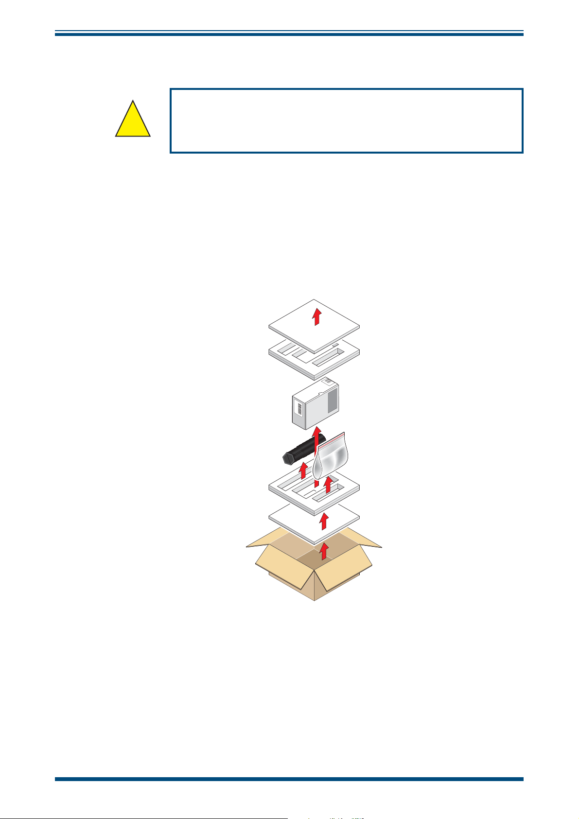
2.1 Unpacking the Instrument
The Cermet II hygrometer and accessories are packed in a box and the method of
unpacking is shown as follows:
to this instrument be undertaken by competent personnel.
Cermet II User’s Manual
Figure 1
2 97049 Issue 25.3, October 2016
Unpacking - Monitor and Accessories
Page 10
Cermet II User’s Manual
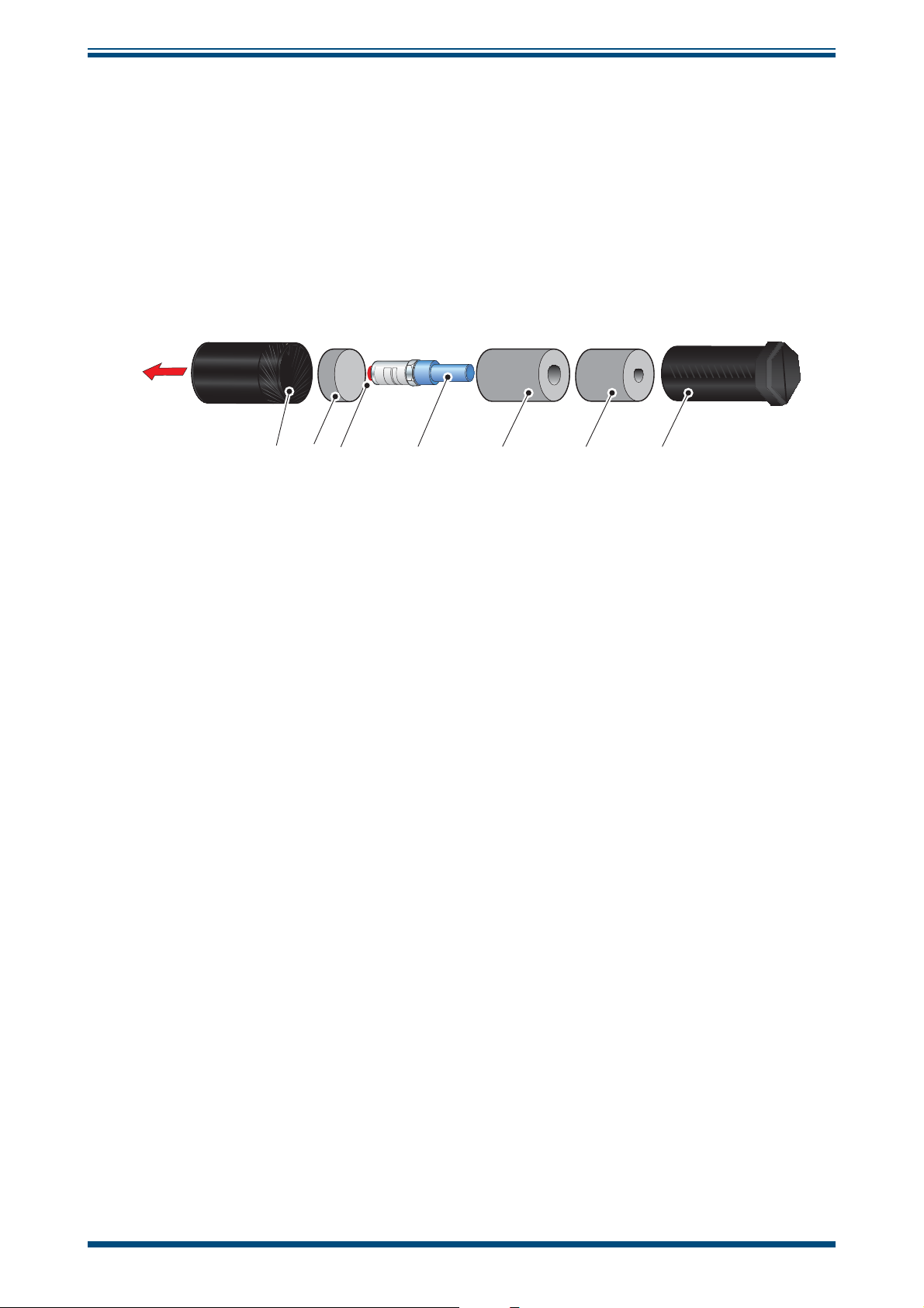
2.1.1 Unpacking the Cermet II Transmitter
On delivery, check that all the following standard components are in the packing tube:
• Cermet II Transmitter
• Bonded Seal
• Certifi cate of Calibration
Unpack the dew-point transmitter tube as follows:
INSTALLATION
7653 421
Figure 2
1. Unscrew the cap (1) from the packing tube (7).
2. Remove the foam block (2).
3. Pull out the transmitter (4) from the tube, complete with the two foam
covers (5) and (6) and the red protective cap (3).
4. Remove the foam covers from the transmitter but leave the blue plastic
protective cover (4) and the red cap (3) in place until ready for installation.
NOTE: The transmitter sensing element is protected while in transit by a blue
cover containing a small desiccant capsule. The connection pins are protected
by a red plastic cap. None of these plastic items are required for the operation
of the transmitter.
Transmitter Unpacking Method
Michell Instruments 3
Page 11
INSTALLATION
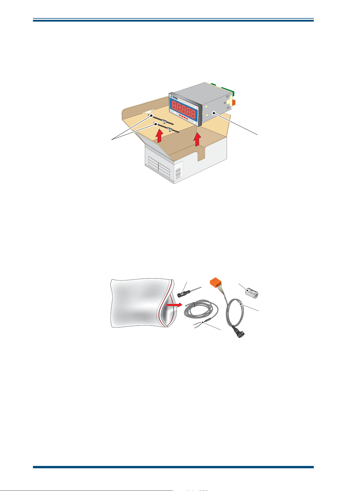
2.1.2 Unpacking the Cermet II Monitor
The monitor (2) is packed, together with its fi xing clamps (1) as shown below.
Cermet II User’s Manual
°Cdp
Cermet II
Advanced Online
°Fdp
Setup
©
ª
1
2.1.3 Accessories Pack
The accessories pack is shown below:
Figure 3
Unpacking - Monitor
1
2
4
3
2
Figure 4
Unpacking - Accessories Pack
4 97049 Issue 25.3, October 2016
Page 12
Cermet II User’s Manual
Cermet II
Hygrometer
User’s Manual
97049 Issue 25.1
June 2015
°C
dp
°
F
dp
C
e
r
m
e
t I
I
Ad
v
an
c
e
d
O
nl
in
e
©
ª
Setup
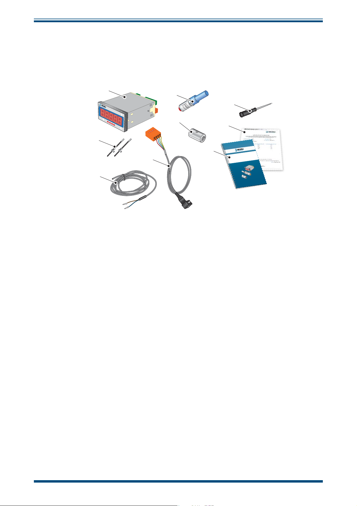
2.2 Cermet II Components
On delivery, please check that all the following standard components are present in the
packing box. Report any shortages immediately.
INSTALLATION
1
4
°Cdp
Cermet II
Advanced Online
°Fdp
Setup
©
9
ª
5
8
2
7
3
6
Figure 5
Components
1. Cermet II Monitor
2. Clamps
3. Transmitter cable assembly
4. Cermet II Transmitter
5. Screwdriver
6. Power cable
7. User’s manual
8. Calibration certifi cate
9. Sample block
Michell Instruments 5
Page 13
INSTALLATION
2.3 Monitor
The monitor has a 5-digit display, set-up on delivery to display a dew-point temperature
range of -100° to +20°Cdp (-148° to +68°Fdp).
Dew-point temperature units are displayed by the last LED located to the far right of
the display. On delivery, °Cdp is set-up. If required, the units can be changed to °F. The
method of confi guring the unit for °F is described in Section 3.2.
Optionally, the instrument can be set-up to read moisture content in parts per million
(ppmV), pounds per million standard cubic feet (lbs/MMSCF) or grams per cubic meter
(g/m3). This option requires the hygrometer to be set-up as detailed in Section 3.2.
Four alarm indications are provided by four LEDs located on the bottom of the display.
These are marked SP1, SP2, SP3, SP4. Access to the alarm relay contacts is provided
on the rear panel. The connection for these alarm relay contacts is shown in
NOTE: Every monitor is factory fi tted with 2 alarm relays as standard.
Cermet II User’s Manual
Figure 15
.
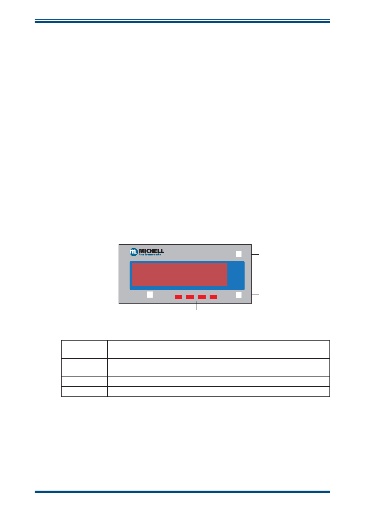
2.4 Monitor Panel Layout
Figure 6
shows the layout of these controls and their respective operational functions.
Setup
1
2
Increases the value of the displayed parameter; moves through each
displayed parameter
Decreases the value of the displayed parameter; moves through each
displayed parameter
3 LED annunciations for Setpoints 1 - 4
4 Saves programming settings, moves between programming steps
h
Cermet II
Advanced Online
ª
h
4
3
©
h
h
1
2
Figure 6
Control Layout and Functions
6 97049 Issue 25.3, October 2016
Page 14
Cermet II User’s Manual
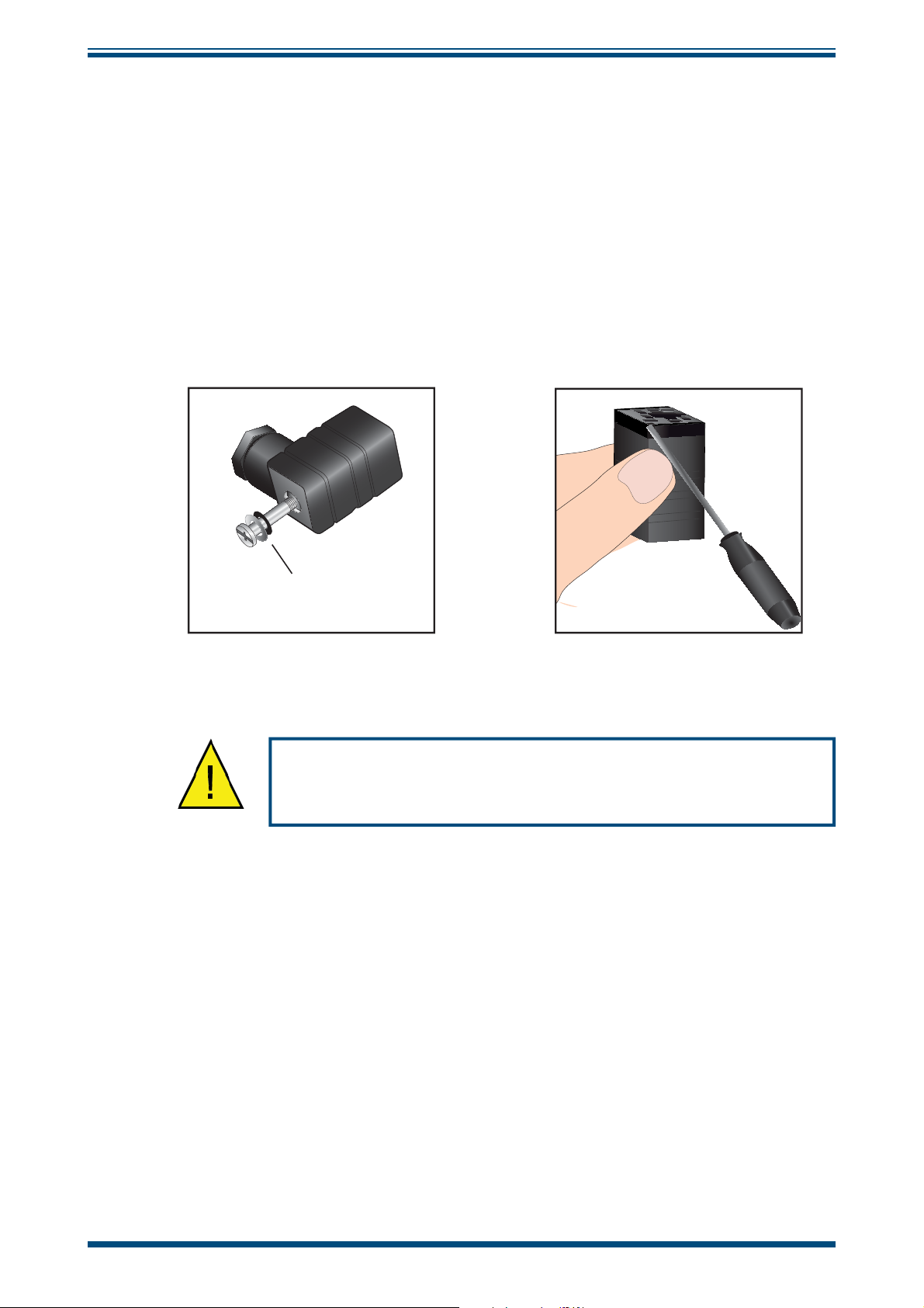
2.5 Preparation of the Transmitter Cable
The transmitter cable is supplied as standard. Replacement of additional cables can be
obtained by contacting your local distributor or Michell Instruments (see www.michell.
com for details).
The cable is pre-wired so no user wiring is required. If the cable needs to be re-wired,
see below:
Cable connection to the Cermet II transmitter is made via the removable connector.
Removing the central screw enables the connector terminal block to be removed from
the outer housing by using a small screwdriver to prise it clear.
INSTALLATION
i
O-ring
and washer
Figure 7
Caution: When removing the central screw ensure that the
small sealing O-ring and the washer are retained on the screw
Connector Terminal Block Removal
and are present during re-installation.
Michell Instruments 7
Page 15

INSTALLATION
2.6 Transmitter Mounting
Prior to installation of the transmitter, unscrew and remove the blue plastic cover and
retain for future use. Take care to prevent any contamination of the transmitter before
installation (handle the transmitter by the main body only, avoiding contact with the
sensor guard).
The transmitter can be mounted into either a fl ow-through sampling block (optional) or
directly inserted into a pipe or duct and can be operated at pressures of up to 45 MPa
(450 barg / 6500 psig) when fi tted with the bonded seal provided.
The recommended gas fl ow rate, when mounted in the optional sampling block, is 1 to
5 Nl/min (2.1 to 10.6 scfh). However, for direct insertion applications, gas fl ow can be
from static to 10 m/sec (32.8 fps).
NOTE: Pass the bonded seal over the 5/8”- 18 UNF mounting thread and
assemble into the sampling location by hand using the wrench fl ats only. DO
NOT grip and twist the transmitter cover when installing the transmitter.
When installed, fully tighten using a wrench until the seal is fully compressed and to the
following torque setting:
Cermet II User’s Manual
5/8” - 18 UNF 30.5 Nm (22.5 ft-lbs)
8 97049 Issue 25.3, October 2016
Page 16
Cermet II User’s Manual
INSTALLATION
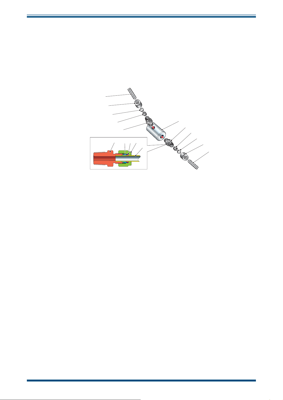
2.6.1 Transmitter Mounting - Sample Block and Gas Connections (Optional)
Sample gas connections are made to the Gas In and Gas Out ports on the sample block
see
Figure 8.
Either port on the sample block may be used as the Gas Input port (i.e.
for connection purposes the ports are interchangeable).
Normally, connections are made via stainless steel pipework, in which case the sensor
block/transmitter assembly will be self supporting. If Tefl on tubing is used it may be
necessary to support the assembly with a body clip.
1
2
3
4
5
2345
1
6
5
4
3
2
1
Figure 8
Sample Block Gas Connections
Both the Input and Output gas connections are ⅛” NPT. It is recommended that both
the Gas Input and Output connections are made made via ⅛” NPT to 6mm or ⅛” NPT
to ¼” stainless steel tube adaptors (2 to 5 -
Figure 8)
. The method of connection to the
sensor block (6) is as follows:
NOTE: The following description relates to 6mm tube fi xings. The sample
block ports are both ⅛” NPT female process connections. Tube adaptors are
not supplied with the equipment but can be obtained by contacting your local
distributor or Michell Instruments (see www.michell.com for details).
1. Cut a suitable length of 6mm (¼” U.S.) stainless steel tubing (1) to the
correct length and, if necessary, bend to shape to suit the location of the
sensor block assembly. NOTE: To facilitate ease of connection to the
port, at least 75mm (3”) of the tubing coming out of the Gas In
port must be straight.
2. Clean off any burrs or metal shavings adhering to the tubing.
3. Screw the ⅛” NPT (¼” U.S.) NPT Swagelok adaptor (5) into the ⅛” NPT
(¼” U.S.) NPT inlet port in the sensor block (6) and tighten to a torque
setting of 35 Nm (25 lbf-ft).
4. Pass the stainless steel tubing (1) through the locking nut (2). NOTE:
Threads towards the gas port.
5. Fit the back ferrule (3) over the stainless steel tubing (1) with the bevelled
end facing the back of the front ferrule (4).
6. Place the front ferrule (4) over the stainless steel tubing (1), bevelled end
towards the adaptor (5).
Michell Instruments 9
Page 17

INSTALLATION
7. Push the stainless steel tubing (1) as far as it will go into the adaptor (5)
and tighten up the locking nut (2) fi nger tight.
8. Hold the adaptor (5) fl ats with a spanner and tighten up the locking
nut (2) to a torque setting of 35 Nm (25 lbf-ft) (1¼ turns). This action
compresses the front ferrule (4) and back ferrule (3) onto the tubing to
form a gas tight seal.
9. Connect up the other gas port as described in steps 1 to 8 above.
To mount the transmitter into the sample block (preferred method), proceed as follows,
refer to
1. Remove the blue protective cover (2) and its desiccant capsule (2a), from
Figure 9.
the tip of the transmitter.
Cermet II User’s Manual
The following procedure must be carried out by a
qualifi ed installation engineer.
2. Fit the bonded seal (3) over the threaded part of the transmitter body.
WARNING: Under no circumstances should the sensor
guard be handled with the fi ngers.
3. Screw the transmitter (1) into the sample block (4) and tighten to a
minimum torque setting of 30.5 Nm (22.5 ft-lbs). NOTE: Use the fl ats
of the hexagonal nut and not the transmitter body.
4. Fit the transmitter cable/connector assembly to the plug located on the
base of the transmitter and tighten the fi xing screw (see Section 2.10).
2
2a
1
4
3
Figure 9
Transmitter Mounting - Sensor Block
10 97049 Issue 25.3, October 2016
Page 18

Cermet II User’s Manual
2.6.2 Transmitter Mounting - Direct Pipeline Connection
INSTALLATION
The transmitter may be directly mounted into a pipe or duct, as shown in
Figure 10.
CAUTION: Do not mount the transmitter too close to the
bottom of a bend where any condensate in the pipeline
might collect and saturate the probe.
The pipe or duct will require a thread to match the transmitter body thread. Fixing
dimensions are shown in
Figure 10
. For circular pipework, to ensure the integrity of a
gas tight seal, a mounting fl ange will be required on the pipework in order to provide a
fl at surface to seal against.
The following procedure must be carried out by
competent personnel.
1. Ensure that the blue protective cover (and its desiccant capsule) has been
removed from the tip of the transmitter.
WARNING: Under no circumstances should the
sensor guard be handled with the fi ngers.
2. Fit a bonded seal (2) over the threaded part of the transmitter body.
3. Screw the transmitter (3) into the pipe (1). Tighten enough to obtain a
gas tight seal. (Torque will depend upon the pipeline material.) NOTE: Do
not overtighten or the thread on the pipework may be stripped.
V
1
2
3
1
L
2
48mm
3
(1.9”)
Figure 10
Transmitter Mounting - Pipe or Duct
Michell Instruments 11
Page 19

INSTALLATION
2.6.3 Transmitter Mounting - With Additional Process Connection Adapter
Cermet II User’s Manual
!
To mount the adapter into the transmitter, proceed as follows (see
1. Ensure that the protective cover (2), and its desiccant capsule (2a), have
been removed from the tip of the transmitter.
2. Fit the bonded seal (3) over the threaded part of the transmitter body.
3. Screw the adapter (4) onto the threaded part of the transmitter and tighten
to 30.5 Nm (22.5 ft-lbs). NOTE: Use the fl ats of the hexagonal nut and
not the transmitter body.
!
4. Screw the transmitter (1) with its seal (3) and adapter (4) into the sample
block (see Section 2.6.1) or pipeline (see Section 2.6.2) and fully tighten
using a wrench until the seal is fully compressed and to the following torque
settings:
The following procedure must be carried out by a qualifi ed
installation engineer.
Figure 11)
WARNING: Under no circumstances should the sensor guard be
handled with the fi ngers.
:
G 1/2” BSP 56 Nm (41.3 ft-lbs)
3/4” - 16 UNF ` 40 Nm (29.5 ft-lbs)
1/2” NPT Use a suitable sealant e.g. PTFE tape using
correct taping procedures
NOTE: Use the fl ats of the hexagonal nut and not the transmitter
body.
2
2a
4
1
3
Figure 11
Transmitter Mounting with Adapter
12 97049 Issue 25.3, October 2016
Page 20

Cermet II User’s Manual
2.7 Monitor Mounting
The monitor is designed for panel mounting and requires a panel cut-out of 46 x 92mm
(1.8 x 3.6”). The recommended panel thickness is 2 to 5mm (0.08 to 0.2”).
To mount the unit, proceed as follows:
°Cdp
Cermet II
Advanced Online
°Fdp
Setup
INSTALLATION
Cermet II
°Cdp
Advanced Online
°Fdp
©
ª
Setup
©
ª
1
3
Figure 12
2
Mounting the Monitor
1. Pass the monitor (1) through the front of the panel (2).
2. Support the monitor and attach mounting fi xing brackets onto the
side of the monitor.
3. Tighten the fi xing screw (3) fi nger tight, against the back of the
panel.
4. Ensure that the monitor is sitting fl ush to the front of the panel (2)
and tighten the fi xing screws evenly against the back of the panel.
Caution: Do not overtighten the screws as this could cause the case to crack.
Michell Instruments 13
Page 21

INSTALLATION
2.8 Electrical Connections
The power supply voltage is indicated on the connection detail label located on the
monitor. As the monitor is provided for continuous operation it does not have an ON/
OFF switch.
The power supply to the monitor may be one of the following, dependant on the type
ordered.
2.8.1 High Voltage Power Supply Input
For high voltage powered display
• 85 to 265 V AC 50/60 Hz and 95 to 370 V DC
It is essential that the connection of electrical supplies to this
instrument be undertaken by competent personnel.
Cermet II User’s Manual
Connect the power supply to the monitor (1) as shown in
V
L
Figure 13.
LV
Wiring Connection:
L Brown wire
V Blue wire
Figure 13
High Voltage Power Supply Connections
14 97049 Issue 25.3, October 2016
Page 22

Cermet II User’s Manual
2.8.2 Low Voltage Power Supply Input
For low voltage powered display
• 18 to 36 V AC and 9 to 60 V DC
INSTALLATION
Connect the power supply to the monitor (1) as shown in
V
L
Figure 14
Low Voltage Power Supply Connections
Figure 14.
LV
Wiring Connection:
L Brown wire
V Blue wire
2.9 Pressure Transducer Connection (Optional)
The monitor provides excitation voltage (24 V DC @ 20 mA) for an auxiliary 2-wire
transmitter used in the dual channel confi guration. Connect (+) of the pressure
transmitter to pin 6 of the monitor and (-) of the pressure transmitter to pin 5 of the
monitor. Refer to
Figure 15
Red
Blue
for details.
RELAY
RELAY
RELAY
SP1
SP3
C
N
O
NON
N
O
C
M
30
29 28 27 26 25 24 23 17
1 2 3 4 5 6 8 9 10 11
3 1 2
DEW-POINT
SENSOR
SP2
N
O
C
PRESSURE SENSOR
- +
PRESSURE
SENSOR
RELAY
C
O
M
SP4
N
O
CONTROL INPUTS
Green
Yellow
SERIAL
INTERFACE
ANALOG
OUTPUT
- +
14
N E
L
POWER
16
15
Figure 15
Electrical Connection Detail
Michell Instruments 15
Page 23

INSTALLATION
2.10 Transmitter Cable Connection
The diagram below shows the identity of the connector terminals.
GREEN
Signal (B)
PIN 1
RED
+Power
PIN 3
PIN 2
BLUE
Ground
YELLOW
Signal (A)
YELLOW
GREEN
BLUE
RED
Cermet II User’s Manual
4
3
2
1
YELLOW Signal (A)
GREEN Signal (B)
BLUE Ground
RED +Power
Figure 16
Cable Connections
The transmitter cable connections are shown in the table below and in the fi gure above.
Connection Red wire Blue wire Green wire Yellow wire
Monitor Pin 1 Pin 2 Pin 3 Pin 4
Transmitter Pin 3 GND Pin 1 Pin 2
Table 1 Cable Connections
When installing the connector, and to ensure that full ingress protection is achieved, the
securing screw (with the O-ring and washer) must be tightened to a minimum torque
setting of 3.4 Nm (2.5 ft-lbs). The transmitter cable used must be a minimum diameter
of 4.6mm (0.2”).
i
O-ring
and washer
Figure 17
Connector Installation
16 97049 Issue 25.3, October 2016
Page 24

Cermet II User’s Manual
3 OPERATION - MONITOR
NOTE: When the instrument is fi rst powered up the display may show a zero
value for about 1 second, followed by a fl ashing
5 seconds, before showing a dew-point value. This is normal and does not
indicate a problem with the instrument.
There are two levels of operation:
OPERATION
OPEN for approximately
User
(No access to programming codes)
Changing display brightness Advanced setpoint programming
Monitoring setpoint values Analog output calibration and scaling
Table 2 Operation Access Levels
3.1 Set-Up Security Feature
To prevent unauthorized access, the monitor has two DIP-switches that can be accessed
by removal of the faceplate (refer to
ON position protects that mode, OFF makes alterations possible.
The
Transmitter connection fault relay set-up
Figure 18)
Advanced
(Access to programming codes)
Auxiliary (optional) channel set-up
Setting the engineering units
Other related advanced functions
.
• The
SETPOINT LOCKOUT switch (SW1) enables or disables Setpoint
Programming mode.
• The
PROGRAM LOCKOUT switch (SW2) enables or disables Code
Programming mode.
Figure 18
MONITOR WITHOUT FACEPLATE
h
O
2
F
1
-73.5C
SP1 SP2 SP3 SP4
F
h
Location of the Lockout Switches
PROGRAM
LOCKOUT
SW2
SETPOINT
LOCKOUT
SW1
Michell Instruments 17
Page 25

OPERATION
3.2 Selecting the Engineering Units
1. Enter the PROGRAM UNLOCK mode (Section 3.1).
Cermet II User’s Manual
2. Press
SETUP and to scroll through the menus.
The monitor can display Dew point in °C or °F, PPM(V), lbs/MMSCF or g/m3 (Natural
Gas). The selection of these units is achieved by setting
CODE 4 and CODE 7 as shown
below:
Required Display Unit CODE 7 CODE 4
Dew point in °C 000 207
Dew point in °F 000 217
PPM
V
100 -
lbs/MMSCF 200 -
3
g/m
(Natural Gas) 300 -
To set the range and resolution for PPM(V), lbs/MMSCF and g/m3 , set digit 3 of
CODE
7 to:
0123
0 1 – 9999 0.1 – 999.9 0.01 – 99.99 0.001 – 9.999
For example, by setting
CODE 7 to 102, displays PPM
maximum of 99.99. Should the measured value exceed 100 PPM
will be displayed.
3.3 Changing the Setpoint Values
1. Enter the SETPOINT UNLOCK mode as described in Section 3.1.
2. Press
are altered by setting
to the required trip level. These are entered directly in the appropriate
engineering units. When displaying PPM(V), then the setpoints are set in
PPM(V) units.
The full matrix of codes for alarm confi guration can be seen in Appendix B, Setpoint
control.
SETUP and simultaneously to access. The setpoints of the relays
SP_n (where n = 1 to 4 and represent SP1 to 4),
with a resolution of 0.01 to a
V
with this setting, oVEr
V
18 97049 Issue 25.3, October 2016
Page 26

Cermet II User’s Manual
3.4 Hysteresis, Make/Break delay & delay type
Associated with each setpoint is a Hysteresis Value, Make delay time, Break delay time
and a Delay type. To gain access to these parameters, set
the features by pressing the or buttons.
The hysteresis value is the value above and below the nominal setpoint at which the
relay trips.
The Make delay time is the time delay between the setpoint being reached and the relay
energizing. The Break delay time is the time delay between the relay being energized
and it de-energizing. The maximum make and break delay time is 9 hours, 6 minutes,
6 seconds, in increments of 1 second.
The setpoint can have four different Delay types:
NorM (normal)
•
•
rEPt (repeat)
OPERATION
SPC_n = xx7, and scroll to
•
1Shot
• PuLSE
If Delay = NorM
If Delay =
If Delay =
If Delay =
rEPt
1Shot
PuLSE
The relay will function normally with the inclusion of the time delays
The make and break delays will repeat continually until the setpoint
source returns to a level that deactivates the setpoint
The relay will energize after the entered delay period and remain
energized
The relay will energize, de-energize after the period entered and
thereafter will remain de-energized
3.5 Analog Output Scaling
1. Enter the PROGRAM UNLOCK mode (see Section 3.1).
2. Press
SETUP, followed by the button, then SETUP again.
3. Press the or buttons to scroll through to the
analog output can be scaled by setting
zero value to the required output at 4 mA (or 0 V) and the full scale
value to the output required at 20 mA (or 10 V).
4. To exit the
button to scroll through the menus.
See Appendix B - Setup Codes for more information on output scaling options.
CAL menu press SETUP, set CAL to 000 and use the
CAL to 061 and setting the
CAL menu. The
Michell Instruments 19
Page 27

OPERATION
3.6 Display Brightness Adjustment
1. To adjust the display brightness press the SETUP and buttons
simultaneously.
Cermet II User’s Manual
2. The display toggles between [
setting.
3. Adjust the display brightness required (from 0 to 7) by pressing the
or buttons.
4. Press
SETUP seven times to exit the programming mode.
3.7 Digital Communications
The monitor is fi tted with ASCII RS232 communication interface as standard (RS485
optional). Communication settings are found as follows:
1. Set CAL to
2. Press SETUP once and then the or buttons to change the baud rate.
Baud rates are 300, 600, 1200, 2400, 4800, 9600, 19,200 and 57.6 K.
3. Press
buttons to change the parity bit. Parity settings are odd, even or off.
100.
SETUP again to advance to the parity bit and then the or
bri] and [5], where 5 is the default
4. Press
are 0 to 255. NOTE: address 0 is not a valid RS485 address.
5. Press
The default communication confi guration is:
The commands used to read and write to the monitor follow the protocol shown below:
Start Character
Meter Address An ASCII number from
SETUP again to advance to the address settings. Address settings
SETUP again to return to CAL.
Baudrate 9600
Data bits 8
Parity none
Flow control none
s or S for the start character (must be fi rst character in
string).
0 to 255 for the meter address.
Read/Write The next character must be an ASCII
w for write. Any other character will abort the operation.
or
R or r for read, or an ASCII W
20 97049 Issue 25.3, October 2016
Page 28

Cermet II User’s Manual
Register Address The register address for the read/write operation is specifi ed
next. It can be either an ASCII number from
registers 1 - 18 can be accessed by entering and ASCII letter
from
character is omitted in a read command, the meter will always
respond with the data value currently on the display. (The
register address must be specifi ed for a write command).
For a full list of the register, that can be read or written to,
see Appendix C.
Separator After the register address in a write command, the next character
must be something other than an ASCII number. This is used
to separate the register address from the data value. It can
be a space or a
*.
a
Data Value After the separator character, the data value is sent. It must be an
ASCII number in the range of
OPERATION
0 to 255 or
A to R (or a to r, not case sensitive). If the address
comma or any other character except a $ or
-32766 to 32766.
Terminate The last character in the message is the message terminator and this
must be either a
a minimum delay of 50mS is inserted before a reply is sent.
If the
inserted before a reply is sent. (the
not appear anywhere else in the message string).
* is used as a terminator, a minimum delay of 2mS is
3.8 Pressure Compensation
Enter the PROGRAM UNLOCK mode as described in Section 3.1.
The monitor has the ability to measure pressure in order to provide a pressure
compensated value for PPM(V), lbs/MMSCF or g/m3.
3.9 Using a Pressure Transducer
In order to enable the use of a pressure transducer set CODE 4 to 307 (dual channel
mode), and while pressing
pressing
SETUP until CODE 4 is displayed.
SETUP, press once. Release both buttons and keep
$ or a *. If the $ is used as a terminator,
$ and * characters must
• To display dew point whilst measuring pressure, set
show dew point in °C; or 317 for dew point in °F.
• To display pressure in psig set
barg set
CODE 6 to 100.
CODE 6 to 000; or to display pressure in
CODE 4 to 307 to
Michell Instruments 21
Page 29

OPERATION
3.9.1 Manual Pressure Input Calibration
The pressure input channel must be confi gured to the range of the pressure transducer.
This is achieved by setting
SCA_2.
SCA_2 = 0.0062 per 100 psig
OFF_2 = pressure range – ((20,000 x (pressure range\1000))\16)
For example, for a pressure transducer with a range of 0 to 1000 psig:
SCA_2 = 0.0062 x 10 = 0.0620
OFF_2 = 1000 – ((20,000 x (1000\1000))\16) = -250
If you are using a pressure transducer in barg, convert the value to psig using a multiplier
of 14.5. For example, for a pressure transducer with a range of 0 to 100 barg:
CAL to 012 and entering values for offset OFF_2 and scale
Cermet II User’s Manual
SCA_2 = 0.0062 x 14.5 = 0.0899
OFF_2 = 1450 – ((20,000 x (1450\1000))\16 = -362
To exit the
screen.
CAL menu, set CAL to 000 and press SETUP six times to return to the main
3.10 Automatic Pressure Input Calibration
Alternatively, the pressure input can be calibrated using a 4-20 mA source.
1. Connect the current source between pin 2 (-ve) and pin 5 (+ve).
2. Set
CAL to 022 and press SETUP. The monitor will then display
ZEro and fl ash 0.
3. Set the mA source to 4.0 mA and press
4. Press
scale pressure value.
5. Set the mA source to 20.0 mA and use the or buttons to set
the required pressure range.
SETUP and the monitor will display SPAn and fl ash the full
SETUP to set 0 at 4 mA.
6. Press
7. Set
SETUP to set the required pressure for 20.0 mA.
CAL to 000 and press the button to leave the menu.
22 97049 Issue 25.3, October 2016
Page 30

Cermet II User’s Manual
3.11 Using a Fixed Pressure Input in Single Channel Mode
In order to display pressure compensated values of ppmV without the use of a pressure
transducer, enter the pressure value manually.
OPERATION
1. Enter the
2. Press
select
3. Select the required pressure compensated value, i.e.
10X for ppm
4. Exit the menus (see Section 3.1) and exit the
mode.
5. Press
pressure. To change the pressure, use the or buttons and
then press
PROGRAM UNLOCK mode (see Section 3.1).
SETUP and the button to scroll through the menus and
CODE 7.
/ ppbV and CAL = 052 (see Table 3).
V
PROGRAM UNLOCK
SETUP for two seconds. The display will show the set
SETUP to confi rm.
CODE 7 =
Michell Instruments 23
Page 31

OPERATION
4 OPERATION - TRANSMITTER
Operation is very simple assuming the following installation techniques are adhered to:
Sampling Hints
Be Sure the Sample is Representative of the Gas Under Test:
The sample point should be as close to the critical measurement point as possible. Also,
never sample from the bottom of a pipe as entrained liquids may be drawn into the
sensing element.
Cermet II User’s Manual
Figure 19
Minimize Dead Space in Sample Lines:
Dead space causes moisture entrapment points, increased system response times and
measurement errors, as a result of the trapped moisture being released into the passing
sample gas and causing an increase in partial vapor pressure.
Figure 20
Remove Any Particulate Matter or Oil from the Gas Sample:
Particulate matter at high velocity can damage the sensing element and similarly, at
low velocity, they may 'blind' the sensing element and reduce its response speed. If
particulate, such as degraded desiccant, pipe scale or rust is present in the sample gas,
use an in-line fi lter, as a minimum level of protection. For more demanding applications
Michell Instruments offers a range of sampling systems (for more information contact
www.michell.com).
Installation Location
Deadspace
Indication of Dead Space
Use High Quality Sample Tube and Fittings:
Michell Instruments recommends that, wherever possible, stainless steel tubing and
fi ttings should be used. This is particularly important at low dew points since other
materials have hygroscopic characteristics and adsorb moisture on the tube walls,
slowing down response and, in extreme circumstances, giving false readings. For
temporary applications, or where stainless steel tubing is not practical, use high quality
thick walled PTFE tubing.
Position Transmitter away from Heat Source:
It is recommended, as good instrumentation practice, that the transmitter is placed
away from any heat source to avoid adsorption/desorption.
24 97049 Issue 25.3, October 2016
Page 32

Cermet II User’s Manual
5 MAINTENANCE
Calibration
Routine maintenance of the Cermet II Transmitter is confi ned to regular re-calibration
by exposure of the transmitter to sample gases of known moisture content to ensure
that the stated accuracy of the transmitter is maintained. Calibration services traceable
to the UK
and Technology
Michell Instruments offers a variety of re-calibration and exchange transmitter schemes
to suit specifi c needs. A Michell representative can provide detailed, custom advice (for
Michell Instruments’ contact information go to www.michell.com).
Transmitter Guard Replacement
The transmitter is supplied with a white HDPE guard (standard) or a stainless steel
guard (if specifi ed at time or order). The method of replacement is the same for both
types.
National Physical Laboratory
(NIST) are provided by Michell Instruments.
(NPL) and the US
MAINTENANCE
National Institute of Standards
HDPE Guard
The HDPE guard provides <10μm protection to the dew-point sensor. It is designed
to show any contamination and the guard should be changed if the surface becomes
discolored.
When replacing the guard, care should be taken to handle the guard by the bottom part
only. Replacement guards (EA2-HDPE) - pack of 10 - can be obtained by contacting
Michell Instruments (www.michell.com) or your local distributor.
HANDLE,
USING
x
GLOVES, BY
BLACK PART
ONLY
E
n
e
H
m
C
u
I
r
6
t
s
0
M
n
9
I
0
Figure 21
Replacement of HDPE Guard
r
Stainless Steel Guard
The stainless steel guard provides <80μm protection to the dew-point sensor. It is
designed to show any contamination and the guard should be changed if the surface
becomes discolored.
When replacing the guard, care should be taken to handle the guard by the bottom part
only. A replacement guard (SSG) can be obtained by contacting Michell Instruments
(www.michell.com) or your local distributor.
Bonded Seal
If the installed bonded seal gets damaged or lost, a pack of 5 replacement bonded seals
can be obtained by contacting Michell Instruments, or your local distributor, and quoting
part number BS-58-PK5.
Michell Instruments 25
Page 33

APPENDIX A
Cermet II User’s Manual
Appendix A
Technical Specifi cations
26 97049 Issue 25.3, October 2016
Page 34

Cermet II User’s Manual
Appendix A Technical Specifi cations
Monitor
APPENDIX A
Display
5 digit LED
7-segment digit, 14.2 mm(0.56”)
Display Color Red
Temperature and Alarm
Indicators
Red LED’s
Performance Specifi cations
Measurement Ranges -19999 to 99999
Dew point ±0.5°C (±1.0°F)
Accuracy
ppm
, lbs/MMSCF and g/m3 ±1% of reading
V
Pressure ±0.5% full-scale reading
Electrical Specifi cations
Dew-Point Input Channel Digital signal from Michell dew-point transmitter
Pressure Input Channel
(optional)
2-wire pressure transducer, 4-20 mA (loop-powered)
Dew point: -100 to +20°C
Output Scaled Range
Moisture content in gas: 0 to 9999 ppm
and g/m
3
, 0 to 1000 lbs/MMSCF
V
Non-standard available upon request
Standard: 4-20 mA
Re-transmittion Output
Signals
Optional: 0-20 mA (max load 500 Ω) or 0 - 10 V optional (min
load 5 K Ω)
User scaleable
Standard: Two relays SP1 and SP2, fully user programmable
Form C contacts rated 10 A, 240 V AC or 8 A, 24 V DC
Alarm Relays
Non-inductive load
Optional: Two extra relays, SP3 and SP4, fully user programmable
Form A contacts rated 5 A, 240 V AC or 5 A, 30 V DC
Non-inductive load
Power Connection 2m (6.56ft), 3 wire
Power Supply
Standard: 85 to 265 V AC, 50/60 Hz or 95 to 370 V DC
Optional: 18 to 36 V AC or 9 to 60 V DC
Power Consumption 10 W max
Copper braid screened cable, 4 core 7/0.2 (0.22mm²), stranded,
tinned copper conductors, PVC, insulated, Melinex taped, black
Transmitter Cable
PVC outer
Fitted with transmitter connector and terminations for monitor
Max length 1000m (3280ft)
Operating Specifi cations
Operating Mode Continous
Operating Temperature 0 to +50°C (+32 to +122°F)
Mechanical Specifi cations
Ingress Protection
Standard: IP54 / NEMA 12 (at front),
Optional: Extra protection cover IP66 / NEMA 4
Dimensions 96 x 48 x 142mm (3.8 x 1.9 x 5.6")
Mounting Panel mounting (1/8 DIN cut out 92 x 45mm (3.62 x 1.77”))
Weight 0.6kg (1.32lbs)
Michell Instruments 27
Page 35

APPENDIX A
Cermet II User’s Manual
Transmitter
Performance Specifi cations
Measurement Range -100 to +20°Cdp (-148 to +68°Fdp) dew point
Accuracy
±1°C dew point (+20 to -60°C) (+68 to -76°F)
±2°C dew point (-60 to -110°C) (-76 to -166°F)
Response Time 5 mins to T95 (dry to wet)
Repeatability 0.5°Cdp (0.9°Fdp)
Calibration 13 point calibration with traceable 7 point calibration certifi cate
Electrical Specifi cations
Output Signal
4-wire connection, digital signal
User-confi gurable over range
Output Dew point
Dew point: -100 to +20°C
Output Scaled Range
Moisture content in gas: 0 to 9999 ppm
and g/m
3
, 0 to 1000 lbs/MMSCF
V
Non-standard available upon request
Supply Voltage 12 to 28 V DC
Load Resistance Max 250 Ω @ 12 V (500 Ω @ 24 V)
Current Consumption 20 mA max
CE Conformity 2004/108/EC
Operating Specifi cations
Operating Temperature -40 to +60°C (-40 to +140°F)
Operating Pressure 45 MPa (450 barg ) max
Mounted in standard sampling block: 1 to 5 Nl/min (2.1 to 10.6
Flow Rate
scfh)
Direct insertion: 0 to 10 m/sec (0 to 32.8 fps)
Temperature Coeffi cient Temperature compensated across operating temperature range
Mechanical Specifi cations
Ingress Protection
IP66 in accordance with standard BS EN60529:1992
NEMA 4 in protection accordance with standard NEMA 250-2003
Housing Material 316 stainless steel
Filter (sensor protection)
Process Connection &
Material
Standard: HDPE Guard < 10μm
Optional: 316 stainless steel sintered guard < 80μm
5/8” - 18 UNF 316 stainless steel
Weight 150g (5.3oz)
Interchangeability Fully interchangeable transmitter
Electrical Connection Hirschmann GDS series (DIN 4350-C)
Diagnostic Conditions
(factory programmed)
Digital Diagnostic
Communications
Condition
Sensor fault
Under-range dew point
Over-range dew point
Communications RS485, 2-wire Modbus RTU
Output
23 mA
4 mA
20 mA
28 97049 Issue 25.3, October 2016
Page 36

Cermet II User’s Manual
APPENDIX B
Appendix B
Setup Codes
Michell Instruments 29
Page 37

APPENDIX B
Appendix B Setup Codes
CAL Calibration modes for input and output
DEFAULT VALUE = 052
Cermet II User’s Manual
Digit 1st digit (left most)
Calibration Mode
Calibration functions as
0
per 2nd and 3rd digit
Set baud rate, parity and
1
serial address
2 N/A N/A Pressure input
3 N/A N/A N/A
4 N/A N/A N/A
5 N/A Manual adjust N/A
6 N/A
2nd digit
Calibration Function
No function No function
Manual calibration (channel as per 3rd
digit)
Analog output scaling (analog channel
as per 3rd digit)
3rd digit
Object for Calibration
Processed result (dew
point, ppm
g/m3)
N/A
, lbs/MMSCF,
V
CODE 1 Tendency Indication, Additional LED’s, Display data source, Flashing,
Decimal points, Rounding
DEFAULT VALUE = 200
Digit 1st digit (left most)
Additional LED’s
LED annunciators are
0
always off
LED annunciators are
on when relays are de-
1
energized
LED annunciators are on
2
when relays are energized
2nd digit
Display Data Source
Processed data - result (dew point,
ppmV, lbs/MMSCF, g/m3)
Processed data - channel 1 (dew
point only)
Processed data - pressure N/A
3rd digit
0 only (No Function)
N/A
N/A
CODE 3 Serial mode and analog output source
DEFAULT VALUE = 000
Digit 1st digit (left most)
Serial Mode
0 ASCII mode
1 N/A
2 N/A
2nd digit
Analog Output 1 Source
Analog output 1 from processed
result data (dew point, ppmV, lbs/
MMSCF, g/m3)
Analog output 1 from processed data
(dew point only)
Analog output 1 from processed data
(pressure)
3rd digit
0 only (No Function)
N/A
N/A
N/A
30 97049 Issue 25.3, October 2016
Page 38

Cermet II User’s Manual
CODE 4 Channel 1 Measurement task, Sampling rate
DEFAULT VALUE = 207
APPENDIX B
Digit 1st digit (left most)
Analog Sample Rate
0 N/A Dew point in degrees C N/A
1 N/A Dew point in degrees F N/A
2 Single channel (50 Hz) N/A N/A
3 Dual channel (50 Hz) N/A N/A
2nd digit
Analog Output 1 Source
3rd digit
0 only (No Function)
CODE 6 Channel 2 Measurement task
DEFAULT VALUE = 000
Digit 1st digit (left most)
Measurement Task
0 Pressure in psig N/A N/A
1 Pressure in barg N/A N/A
2nd digit
0 only (No Function)
3rd digit
0 only (No Function)
CODE 7 Result processing
DEFAULT VALUE = 000
Digit 1st digit (left most)
Measurement Task
0 Dew point N/A 1 – 9999
1 ppm
2 lbs/MMSCF N/A 0.01 – 99.99
3 g/m
V
3
(Natural Gas) N/A 0.001 – 9.999
2nd digit
0 only (no function)
N/A 1 – 999.9
3rd digit
Range for Result
Setpoint control 1 – 6 Relay latching, relay setup, source
DEFAULT VALUE = 000 (Prog/Down menu after setpoints)
Digit 1st digit (left most)
Relay Sense
Relay energized above
0
setpoint value
Relay energized below
1
setpoint value
2 N/A Pressure De-energized relay
3 N/A Open transmitter connection N/A
4 N/A Open / short circuit transmitter
5 N/A Open / short circuit thermistor
6 N/A All transmitter faults
7 N/A N/A
2nd digit
Setpoint Source
Processed result data (dew point,
ppmV, lbs/MMSCF, g/m3)
Dew point only Relay latched
3rd digit
Setpoint Function SP1 – SP4
No function
Relay off for open transmitter
connection
Relay on for open transmitter
connection
Relay toggles at 1 Hz for
transmitter connection fault
Set-up hysteresis, make/
break delay and delay type
Michell Instruments 31
Page 39

APPENDIX C
Cermet II User’s Manual
Appendix C
Register Settings Accessible
by Digital Communication
32 97049 Issue 25.3, October 2016
Page 40

Cermet II User’s Manual
APPENDIX C
Appendix C Register Settings Accessible by Digital Communication
Register
Number
1 Alarm Status
2 N/A
3 Processed Data – Result
4 Processed Data – Channel 1 (dew-point)
5 Processed Data – Channel 2 (pressure)
6 Setpoint 1
7 Setpoint 2
8 Setpoint 3
9 Setpoint 4
10 to 23 N/A
24 Scale Value – Result
25 Scale Value – Channel 1
26 Scale Value – Channel 2
27 Offset Value – Result
28 Offset Value – Channel 1
29 Offset Value – Channel 2
30 to 33 N/A
34 D/A Zero – Analogue O/P 1
35 N/A
36 D/A Full Scale – Analogue O/P 1
37 to 64 N/A
65 Hysteresis - Setpoint 1
66 Hysteresis - Setpoint 2
67 Hysteresis - Setpoint 3
68 Hysteresis - Setpoint 4
69 to 70 N/A
71 Make Delay - Setpoint 1
72 Make Delay - Setpoint 2
73 Make Delay - Setpoint 3
74 Make Delay - Setpoint 4
75 to 76 N/A
77 Break Delay - Setpoint 1
78 Break Delay - Setpoint 2
79 Break Delay - Setpoint 3
80 Break Delay - Setpoint 4
81 to 128 N/A
129 Cal Mode
130 Code 1
131 Code 2
132 Code 3
Function Read Only
Michell Instruments 33
Page 41

APPENDIX C
138 to 141 Reserved
146 to 147 N/A
151 to 152 N/A
155 to 192 N/A
133 Code 4
134 Code 5
135 Code 6
136 Code 7
136 Code 8
142 Setpoint 1 Control Register
143 Setpoint 2 Control Register
144 Setpoint 3 Control Register
145 Setpoint 4 Control Register
148 Brightness
149 Baudrate Settings
150 Serial Address
153 Model Number
154 Version Number
193 Delay Type – Setpoint 1
194 Delay Type – Setpoint 2
195 Delay Type – Setpoint 3
196 Delay Type – Setpoint 4
Cermet II User’s Manual
34 97049 Issue 25.3, October 2016
Page 42

Cermet II User’s Manual
APPENDIX D
Appendix D
EU Declaration of Conformity
Michell Instruments 35
Page 43

APPENDIX D
Appendix D EU Declaration of Conformity
Cermet II User’s Manual
36 97049 Issue 25.3, October 2016
Page 44

Cermet II User’s Manual
APPENDIX E
Appendix E
Quality, Recycling
& Warranty
Information
Michell Instruments 37
Page 45

APPENDIX E
Cermet II User’s Manual
Appendix E Quality, Recycling & Warranty Information
E.1 Pressure Equipment Directive (PED) 97/23/EC
The above Directive has been implemented in United Kingdom Law by the Pressure Equipment
Regulations 1999.
The Regulations require that all pressure equipment and assemblies within the scope of the Pressure
Equipment Directive must be safe when placed on the market or put into service.
Michell Instruments’ products have been assessed and, as referenced against the Classifi cation Charts
detailed in Annex II of the Directive, do not fall into the requirements for CE marking compliance
with the Pressure Equipment Directive.
Article 3, paragraph 3 states that any product containing a pressurized fl uid that does not qualify for
compliance should, nevertheless, be constructed with Sound Engineering Practice (SEP).
Michell Instruments attests here that its products have been designed, manufactured & tested to
assure safe operation, and in accordance with Sound Engineering Practices.
E.2 Recycling Policy
Michell Instruments is concerned with the protection of the environment. It is our commitment to
reduce and eliminate from our operations, wherever possible, the use of substances which may be
harmful to the environment. Similarly, we are increasingly using recyclable and/or recycled material
in our business and products wherever it is practical to do so.
To protect natural resources and to promote material reuse, please separate batteries from other
types of waste and recycle responsibly. If batteries are not properly disposed of, these substances
can cause harm to human health and the environment
The product that you have purchased may contain recyclable and/or recycled parts and we will be
happy to provide you with information on these components if required. For further information
please see the following sections.
E.3 WEEE Compliance
Directive 2012/19/EU 4 July 2012 on Waste Electronic and Electrical Equipment (WEEE)
The Waste Electronic and Electrical Equipment (WEEE) Directive places rules upon European
manufacturers of electrical and electronic equipment. The directives’ aim is to reduce the impact
that electronic devices have on the environment.
Michell Instruments is in full compliance with the WEEE Directive and is registered with an approved
recycler (Registration No. WEE/JB0235YW) and treats the requirement of the directive and the
protection of the environment with the utmost importance. All Michell Instruments’ products are
appropriately marked indicating their requirement for recycling.
It may be required to return certain instruments for treatment at the end of their working life.
Feb 2013
38 97049 Issue 25.3, October 2016
Page 46

Cermet II User’s Manual
E.4 RoHS2 Compliance
Directive 2011/65/EU of the European Parliament and of the Council of 8 June 2011
The Restriction of Hazardous Substances (RoHS) Directive places rules upon European manufacturers
of electrical and electronic equipment. The directives’ aim is to reduce the impact that electronic
devices have on the environment.
According to the EC Directive 2002/95/EC, Michell Instruments’ products qualify as Category 9,
Control and Monitoring Equipment. Under the 2002/95/EC Directive, Category 9 products are exempt
from compliance with the Directive.
However, the careful design of all Michell Instruments’ products takes into consideration the
requirements of the Directive and, wherever possible, compliance is achieved. All future products
will be developed entirely using compliant materials. Furthermore, Michell Instruments is taking
active steps to remove non-compliant materials and components from existing products wherever
these may occur. Presently, none of the non-compliant materials are known to occur in Michell
Instruments’ products.
APPENDIX E
The new Directive 2011/65/EU (RoHS2) entered into force on 21 July 2011 and required all Member
States to transpose the provisions into their respective national laws by 2 January 2013.
Under the provisions of the RoHS2 EU Directive 2011/65/EU (Article 3, [24]) defi nes ‘Control and
Monitoring Equipment’ specifi cally as ‘monitoring and control instruments designed exclusively for
industrial or professional use’.
RoHS2 EU Directive 2011/65/EU states the closing date for compliance of any Control and Monitoring
Equipment product sold into the EU market place as 22nd July 2017.
However, the careful design policy of all Michell Instruments’ products continues to attain compliance
in the shortest practical timescales and strives to ensure that less than 0.1% of total mass per
product, of all non-compliant materials, appear within them. Michell Instruments continues to
monitor suppliers and material sources to ensure that compliance of goods provided is maintained.
January 2013
E.5 Warranty
Unless otherwise agreed, the Supplier warrants that, as from the date of delivery for a period of 12
months, the goods and all their component parts, where applicable, are free from any defects in
design, workmanship, construction or materials.
The Supplier warrants that the services undertaken shall be performed using reasonable skill and
care, and be of a quality conforming to generally accepted industry standards and practices.
Except as expressly stated, all warranties whether express or implied, by operation of law or
otherwise, are hereby excluded in relation to the goods and services to be provided by the Supplier.
All warranty services are provided on a return to base basis. Any transportation costs for the return
of a warranty claim shall reside with the Customer.
Michell Instruments 39
Page 47

APPENDIX E
E.6 REACH Compliance
Regulation (EC) No. 1907/2006
Registration, Evaluation, Authorisation and Restriction of Chemicals (REACH)
Michell Instruments is a manufacturer of moisture measurement and gas analysis instrumentation
and is a ‘downstream’ user of chemicals, as described by the EU Council Directive 76/769/EEC. The
products we supply are not raw chemical products (goods).
Under normal and reasonably foreseeable circumstances of application, the goods supplied to you
shall not contain or release any prohibited chemicals. No listed SVHC (Substances of Very High
Concern) appear within products manufactured by Michell Instruments. Therefore the 0.1% mass
per product, or total usage of 1 tonne/year, will never be exceeded. For these reasons we are neither
required by obligation for registration nor for the creation of material safety data sheets (MSDS) for
our products.
Cermet II User’s Manual
Our continued review of the SVHC Candidate List and
compliant.
Michell Instruments maintains a hazardous material register in which MSDS data sheets are collated,
and we will check that our suppliers will comply to REACH requirements for all materials and
substances we use in the processes of our manufacturing.
In the unlikely event that any chemicals of concern appear in our products in quantities greater than
0.1% of total mass per product we will immediately inform you by correspondence according to the
REACH Article 33 requirements. Our current appraisal is, however, that we do not expect or foresee
such an incidence.
January 2013
E.7 Return Policy
If a Michell Instruments’ product malfunctions within the warranty period, the following procedure
must be completed:
1. Notify a Michell Instruments’ distributor, giving full details of the problem, the
model variant and the serial number of the product.
latest additions is to ensure we remain
2. If the nature of the problem indicates the need for factory service then the
instrument should be returned to Michell Instruments, carriage prepaid, preferably
in the original packaging, with a full description of the fault and the customer
contact information.
3. Upon receipt, Michell Instruments will evaluate the product to determine the cause
of the malfunction. Then, one of the following courses of action will be taken:
• If the fault is covered under the terms of the warranty, the
instrument will be repaired at no cost to the owner and returned.
• If Michell Instruments determines that the fault is not covered
under the terms of the warranty, or if the warranty has expired,
an estimate for the cost of the repairs, at standard rates, will be
provided. Upon receipt of the owner’s approval to proceed, the
product will be repaired and returned.
40 97049 Issue 25.3, October 2016
Page 48

Cermet II User’s Manual
E.8 Calibration Facilities
Michell Instruments’ calibration facilities are among the most sophisticated in the world and have
been recognized for their excellence.
Traceability to the National Physical Laboratory (NPL) UK is achieved through our UKAS Accreditation
(Number 0179). This covers dew point over the range -90 to +90°C (-130 to +194°F) and also
Relative Humidity.
Dew-point calibrations are also traceable to the National Institute for Standards & Technology (NIST)
USA over the range -75 to +20°C (-103 to +68°F).
NOTE: Standard traceable calibration certifi cates for instruments and sensors are not
issued under our UKAS accreditation.
E.9 Manufacturing Quality
Michell Instruments is registered with the British Standards Institute for Quality Assurance to:
APPENDIX E
BS EN ISO 9001: 2008
Rigorous procedures are performed at every stage of production to ensure that the materials of
construction, manufacturing, calibration and fi nal test procedures meet the requirements laid down
by our BSI approved Quality System.
Please contact Michell Instruments (www.michell.com) if the product does not arrive in perfect
working order.
E.10 FCC (EMC Rquirements for North America)
This device complies with part 15 of the FCC Rules. Operation is subject to the following two
conditions:
1. This device may not cause harmful interference.
2. This device must accept any interference, including interference that may cause
undesired operation.
This equipment has been tested and found to comply with the limits for a Class A digital device,
pursuant to part 15 of the FCC Rules. These limits are designed to provide reasonable protection
against harmful interference when the equipment is operated in a commercial environment. This
equipment generates, uses, and can radiate radio frequency energy and, if not installed and used
in accordance with the user manual, may cause harmful interference to radio communications.
Operation of this equipment in a residential area is likely to cause harmful interference in which
case the user will be required to correct the interference at his own expense. This product must be
operated as per the operating instructions provided. Do not make any alterations or modifi cations
to the product. Any unauthorized alterations or modifi cations made to this product may require you
to stop operating the product.
Canadian Radio Interference Regulations.
This Class A digital product complies with Canadian ICES-001. Règlement canadien sur les
interférences radio. Ce produit numérique de classe A est conforme à la norme NMB-001.
Michell Instruments 41
Page 49

APPENDIX F
Cermet II User’s Manual
Appendix F
Return Document
&
Decontamination Declaration
42 97049 Issue 25.3, October 2016
Page 50

Cermet II User’s Manual
Appendix F Return Document & Decontamination Declaration
'HFRQWDPLQDWLRQ&HUWL¿FDWH
IMPORTANT NOTE: Please complete this form prior to this instrument, or any components, leaving your
site and being returned to us, or, where applicable, prior to any work being carried out by a Michell
engineer at your site.
Instrument Serial Number
Warranty Repair? YES NO Original PO #
Company Name Contact Name
Address
Telephone # E-mail address
Reason for Return /Description of Fault:
APPENDIX F
Has this equipment been exposed (internally or externally) to any of the following?
Please circle (YES/NO) as applicable and provide details below
Biohazards YES NO
Biological agents YES NO
Hazardous chemicals YES NO
Radioactive substances YES NO
Other hazards YES NO
Please provide details of any hazardous materials used with this equipment as indicated above (use continuation sheet
if necessary)
Your method of cleaning/decontamination
Has the equipment been cleaned and decontaminated? YES NOT NECESSARY
Michell Instruments will not accept instruments that have been exposed to toxins, radio-activity or bio-hazardous
PDWHULDOV)RUPRVWDSSOLFDWLRQV LQYROYLQJVROYHQWVDFLGLFEDVLFÀDPPDEOHRUWR[LFJDVHVDVLPSOHSXUJHZLWKGU\
JDVGHZSRLQW&RYHUKRXUVVKRXOGEHVXI¿FLHQWWRGHFRQWDPLQDWHWKHXQLWSULRUWRUHWXUQ
Work will not be carried out on any unit that does not have a completed decontamination declaration.
Decontamination Declaration
I declare that the information above is true and complete to the best of my knowledge, and it is safe for Michell
personnel to service or repair the returned instrument.
Name (Print) Position
Signature Date
F0121, Issue 2, December 2011
Michell Instruments 43
Page 51

NOTES:
Cermet II User’s Manual
44 97049 Issue 25.3, October 2016
Page 52

http://www.michell.com
 Loading...