

Page 1
RedEdge 3 User Manual Rev 06
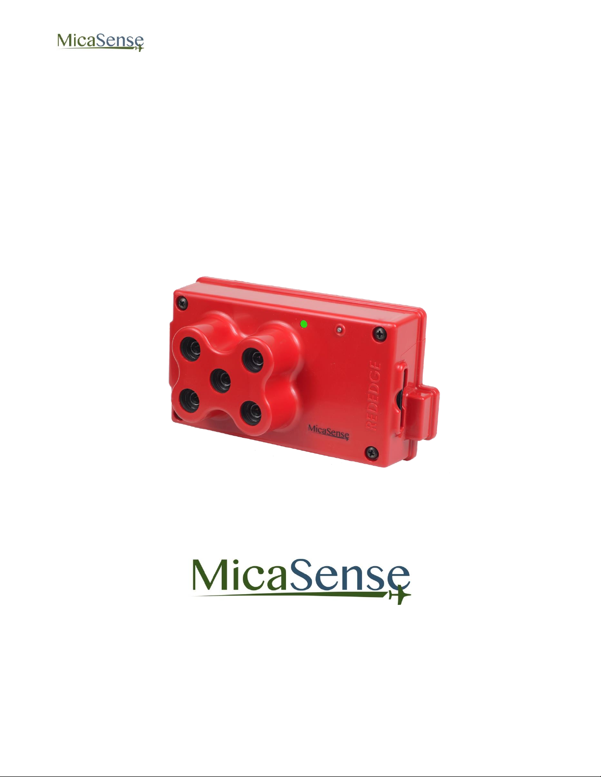
MicaSense RedEdge™ 3
Multispectral Camera
User Manual
Rev 06 – October 2015
MicaSense, Inc.
Seattle, WA
© 2015 MicaSense, Inc. Page 1 of 33
Page 2
RedEdge 3 User Manual Rev 06
TABLE OF CONTENTS
1. REDEDGE 3 OVERVIEW 4
2. USING THE REDEDGE CAMERA 5
2.1. GETTING STARTED: CONNECTIONS 5
2.2. USING THE REDEDGE CAMERA 7
3. CAMERA CONFIGURATION AND LIVE VIEW 9
3.1. ESTABLISHING WIFI CONNECTION 9
3.2. HOME PAGE 10
3.3. LIVE VIEW PAGE 11
3.4. COVERAGE PAGE 13
3.5. SETTINGS PAGE 17
3.5.1. TIMER MODE 18
3.5.2. EXTERNAL TRIGGER MODE 19
3.5.3. OVERLAP MODE: 20
3.5.4. ADVANCED CONFIGURATION: 21
3.5.5. MANUAL EXPOSURE: 22
4. MAPPING OPERATIONS 23
5. EXTERNAL CONNECTIONS 24
6. FILE STORAGE 25
7. DATA COLLECTION RECOMMENDATIONS 26
8. CHECKLIST FOR OPERATION 29
9. FIRMWARE UPDATE 31
10. SPECIFICATIONS 32
© 2015 MicaSense, Inc. Page 2 of 33
Page 3

RedEdge 3 User Manual Rev 06
DISCLAIMER OF WARRANTIES AND LIMITATION OF LIABILITY
MICASENSE MAKES NO REPRESENTATION OR WARRANTY, EXPRESS OR IMPLIED, WITH RESPECT
TO THE REDEDGE CAMERA. MICASENSE DISCLAIMS ANY LIABILITY FOR INDIRECT, CONSEQUENTIAL,
PUNITIVE, OR SPECIAL DAMAGES, INCLUDING WITHOUT LIMITATION DAMAGES FOR LOST DATA,
LOST REVENUE, LOST PROFITS, OR REPLACEMENT PRODUCT COSTS ARISING OUT OF THE
PURCHASE, USE, OR PERFORMANCE OF THE REDEDGE CAMERA, UNDER ANY THEORY OF LIABILITY,
EVEN IF MICASENSE HAS BEEN ADVISED OF THE POSSIBILITY OF SUCH DAMAGES. MICASENSE
DISCLAIMS ANY IMPLIED WARRANTY OF MERCHANTABILITY OR FITNESS FOR A PARTICULAR
PURPOSE, AND DISCLAIMS ANY IMPLIED WARRANTY ARISING FROM A COURSE OF PERFORMANCE,
DEALING, USAGE, OR TRADE PRACTICE. THE PRICE OF PRODUCTS DISTRIBUTED BY MICASENSE OR
ITS AUTHORIZED DEALERS REFLECTS THE ALLOCATION OF RISK ARISING FROM THE WARRANTY
EXCLUSIONS AND THIS DISCLAIMER AND LIMITATION OF LIABILITY.
© 2015 MicaSense, Inc. Page 3 of 33
Page 4
RedEdge 3 User Manual Rev 06
1. RedEdge 3 Overview
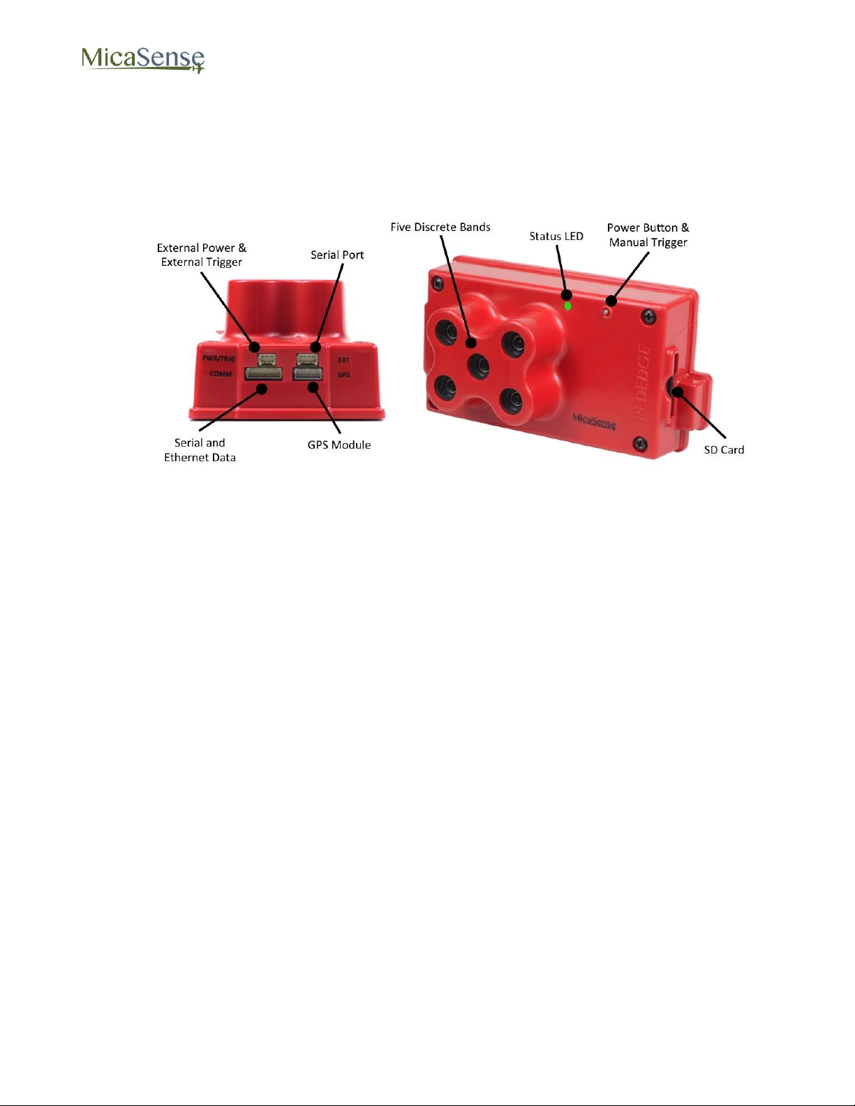
The MicaSense RedEdge 3 is a professional multispectral camera capable of simultaneous
capture of five discrete spectral bands to generate precise and quantitative information on the
vigor and health of crops.
Figure 1: RedEdge Camera Features and Connections
© 2015 MicaSense, Inc. Page 4 of 33
Page 5
RedEdge 3 User Manual Rev 06
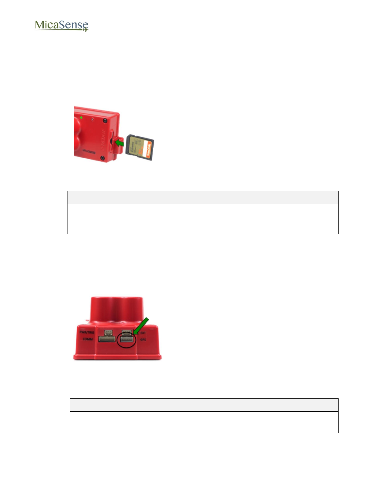
Insert SD Card
Insert SD card, label side facing up, until it
clicks into place.
To remove SD card, press the edge of the
card until the spring mechanism unlatches.
NOTE
An SDHC Class 10 SD card with a write-speed capability of at least 45 MB/s is
required (32 GB SanDisk Extreme recommended). SDXC SD cards are not
compatible with the RedEdge camera.
Connect GPS Module
If stand-alone GPS module is used:
o Connect one end of 6-pin cable to
camera connector labeled “GPS”.
o Connect other end of 6-pin cable to
GPS module connector labeled
“GPS”.
For more advanced integrations where
GPS data is provided by the autopilot or
other GPS source, refer to RedEdge
Integration Guide.
To remove connectors, do not pull on
wires; instead use a small flathead
screwdriver to pry out the connector. See
Section 5.
CAUTION
Always connect the GPS module to the camera before turning on the camera.
Failure to do so may damage the GPS module.
2. Using The RedEdge Camera
2.1. Getting Started: Connections
© 2015 MicaSense, Inc. Page 5 of 33
Page 6
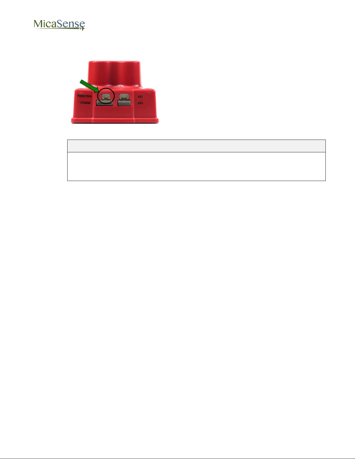
Connect Power Cable
Refer to RedEdge Integration Guide for
details on power requirements and
connector pinout.
Connect power cable to connector
labeled “PWR/TRIG”.
To remove connector, do not pull on
wires; instead use a small flathead
screwdriver to pry out the connector. See
Section 5.
CAUTION
Power must not exceed 5.5 V DC. Ensure correct pinout and polarity before
connecting power. Failure to follow these instructions may result in permanent
damage to the camera.
RedEdge 3 User Manual Rev 06
© 2015 MicaSense, Inc. Page 6 of 33
Page 7
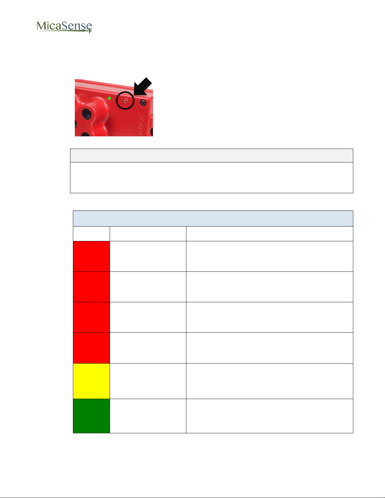
RedEdge 3 User Manual Rev 06
Power ON the Camera
Press and release the ON/OFF button.
The Status LED will remain OFF while the
camera is initializing (approx. 5 seconds).
After initialization has completed, Status LED
will flash at approximately once every 1.5
seconds.
NOTE
The camera will automatically turn ON when power is first applied to the external
power connector. If the camera is manually turned OFF, it can be re-powered ON
by pressing the ON/OFF button.
Status LED Indicators
Color
Type
Meaning
Red
1 Flash
No SD card installed
Red
2 Flashes
SD card is full or close to full
Red
3 Flashes
GPS timeout
Red
4 Flashes
Low power source indication
Yellow
1 Flash
GPS unit detected, but does not have a fix
Green
1 Flash
Camera is ready for operation (GPS is good
and SD card has > 2 GB space available)
2.2. Using the RedEdge Camera
© 2015 MicaSense, Inc. Page 7 of 33
Page 8
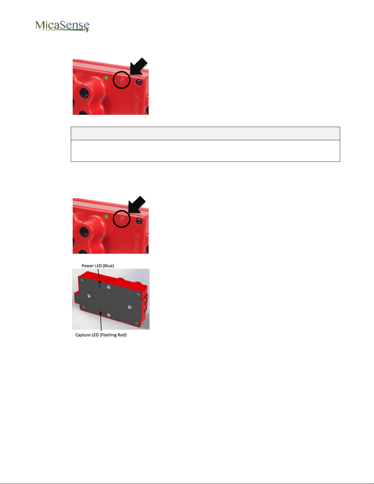
RedEdge 3 User Manual Rev 06
To Power OFF the Camera:
Press and hold the ON/OFF button for at least 4
seconds.
The Status LED will stop flashing once the
camera has shut down.
CAUTION
Always power OFF the camera before removing the SD card. Failure to do so
may corrupt some of the files in the SD card.
Capturing Images (Manual Trigger)
With the camera turned ON and SD card
installed, press and release the trigger button.
The camera will command a capture and the red
LED on the back cover will flash three times to
indicate that a capture has been taken and the
data is being written to the SD card.
© 2015 MicaSense, Inc. Page 8 of 33
Page 9
RedEdge 3 User Manual Rev 06
Home Page
Live View Page
Coverage Page
Settings Page
3. Camera Configuration and Live View
The RedEdge camera hosts a Wi-Fi access point that is used in conjunction with any Wi-Ficapable device for configuration of the camera and live preview of images acquired with the
camera.
3.1. Establishing WiFi Connection
Any device (computer, tablet, or smart phone) can be used to establish a connection with the
camera. To establish the WiFi connection:
1. Turn on the camera and wait for initialization process to complete
2. Use the device’s WiFi configuration method to search for a WiFi access point called
“rededgeXXXXXXX”, where “XXXXXXX” is the 7-digit serial number of the camera.
3. The password for this WiFi access point is “micasense”.
Once connected to the camera’s WiFi, open any web browser and access the camera’s web
page by typing in “192.168.10.254” in the address bar of the browser.
There are 4 main “pages” for the camera:
© 2015 MicaSense, Inc. Page 9 of 33
Page 10
RedEdge 3 User Manual Rev 06
3.2. Home Page
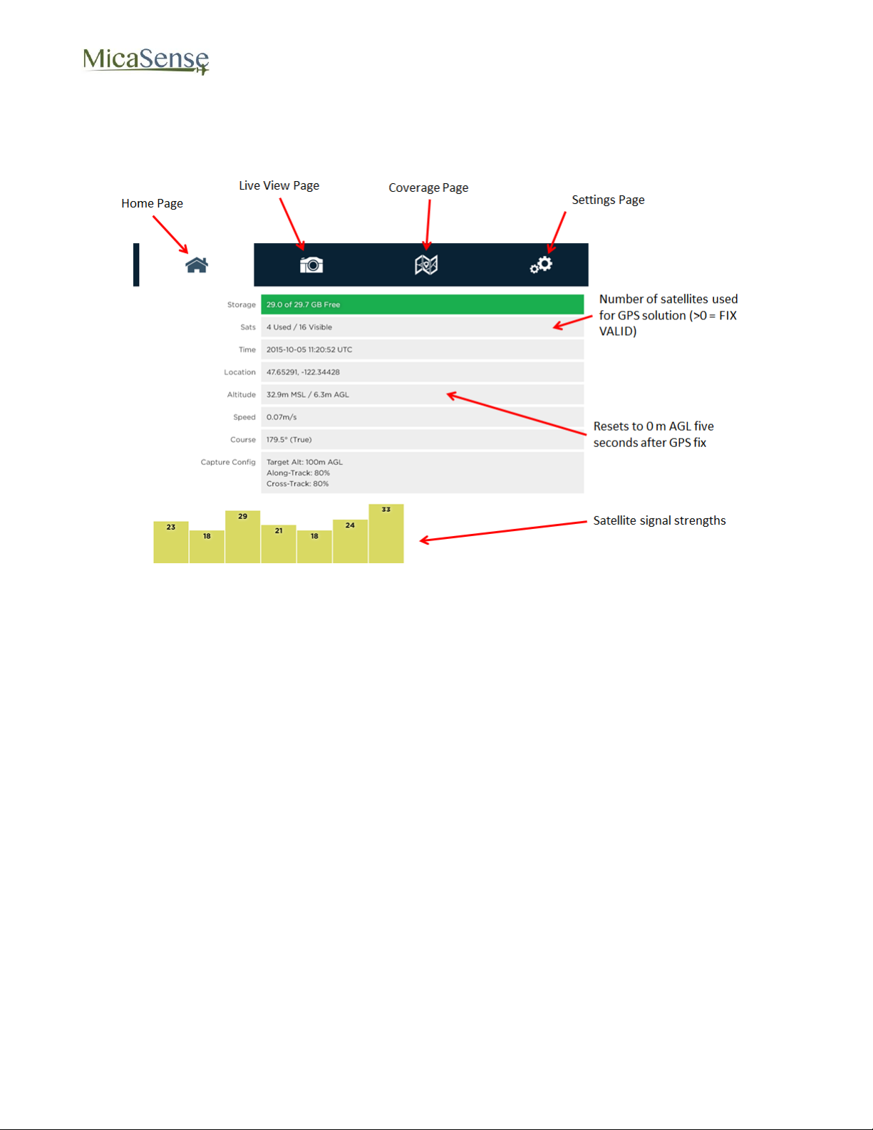
Provides status information for the camera and the GPS receiver that is connected to it.
Figure 2: Home Page
© 2015 MicaSense, Inc. Page 10 of 33
Page 11
RedEdge 3 User Manual Rev 06
3.3. Live View Page
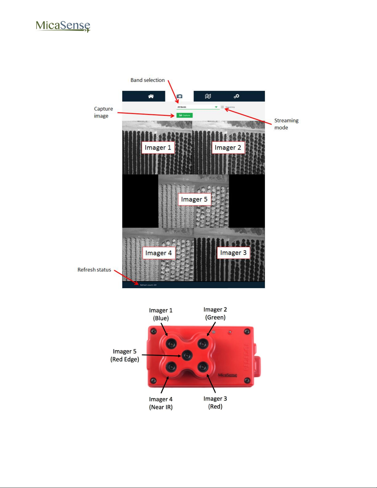
Provides a live preview of images captured with the camera.
Figure 3: Live View Page
Figure 4: Imager Nomenclature
© 2015 MicaSense, Inc. Page 11 of 33
Page 12
RedEdge 3 User Manual Rev 06
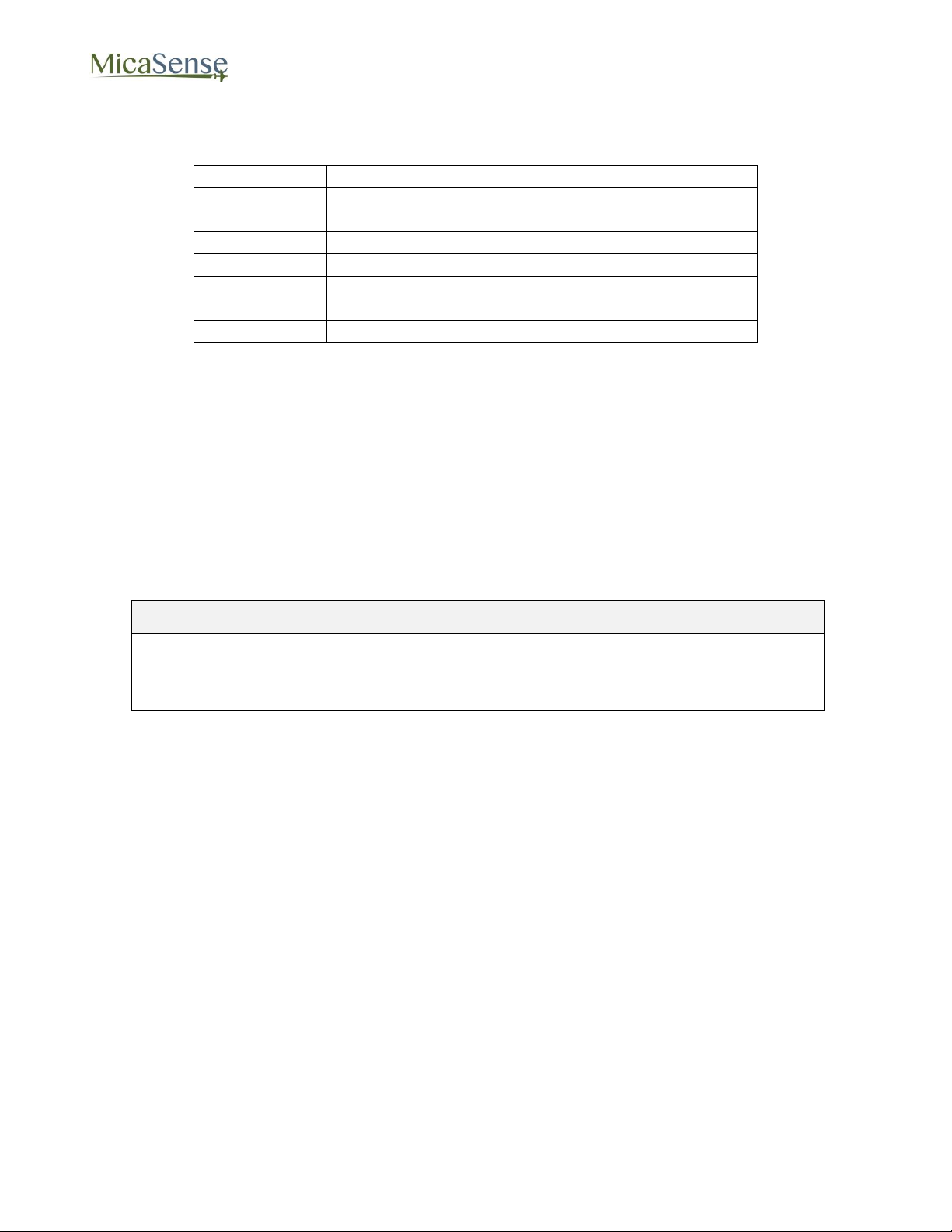
Setting
Action
Multi
Shows all five single-band images at once in a
matrix
Band 1
Shows imager #1 (Blue filter)
Band 2
Shows imager #2 (Green filter)
Band 3
Shows imager #3 (Red filter)
Band 4
Shows imager #4 (Near IR filter)
Band 5
Shows imager #5 (“Red Edge” filter)
NOTE
Streaming mode is intended for live-preview. It is recommended that streaming
mode be disabled before any other operations (particularly before enabling AutoCapture mode).
Whenever the camera captures images, the image(s) will be displayed in the Live View page
based on the setting of the “Band” pull-down menu
Capture: The Capture button forces a capture for the camera, and is equivalent to pressing
the manual trigger button on the camera.
Streaming: The Streaming checkbox is used for near-real-time preview images from the
camera. When the Streaming mode is enabled, the images shown will update as quickly as
the camera can support it (currently approx. twice a second). Note that Streaming mode does
not save any images to the SD card. It just enables fast capture of the camera for preview
purposes only.
© 2015 MicaSense, Inc. Page 12 of 33
Page 13
RedEdge 3 User Manual Rev 06
3.4. Coverage Page
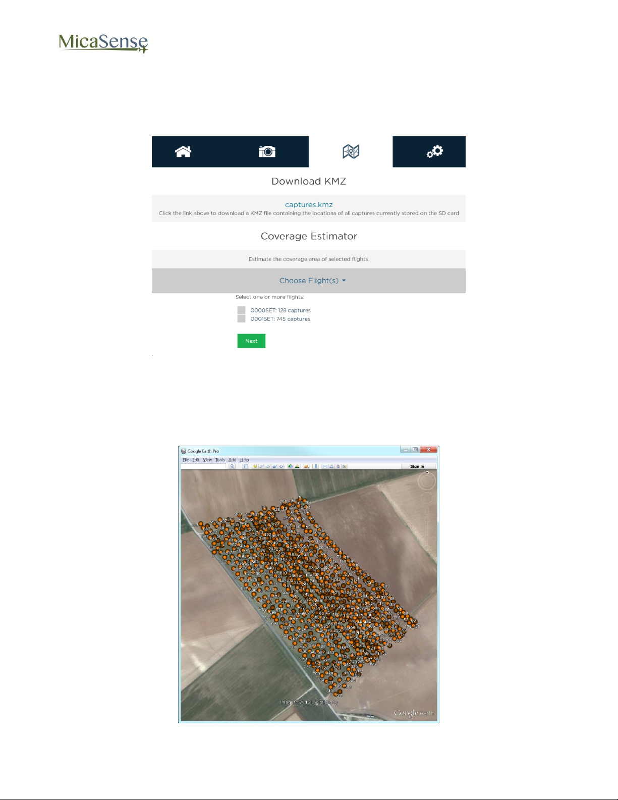
The coverage page provides information on the geographic location where images in the SD
card were captured based on the GPS module information.
Figure 5: Coverage Page
Clicking the “captures.kmz” link will cause the camera to generate a KMZ file that will be
downloaded by your browser. The KMZ file contains the lat/lon/alt of all captures in the SD
card and can be used to verify coverage after a flight or series of flights. The KMZ file can be
opened using Google Earth or a GIS application.
Figure 6: KMZ File Can Be Viewed In Applications Like Google Earth
© 2015 MicaSense, Inc. Page 13 of 33
Page 14
RedEdge 3 User Manual Rev 06
The Coverage Estimator is a tool for quickly checking that a flight has sufficient overlap.
From the initial Coverage Page, select one or more image sets to estimate and click “Next”
(note: image sets must be geographically close together in order to work properly).
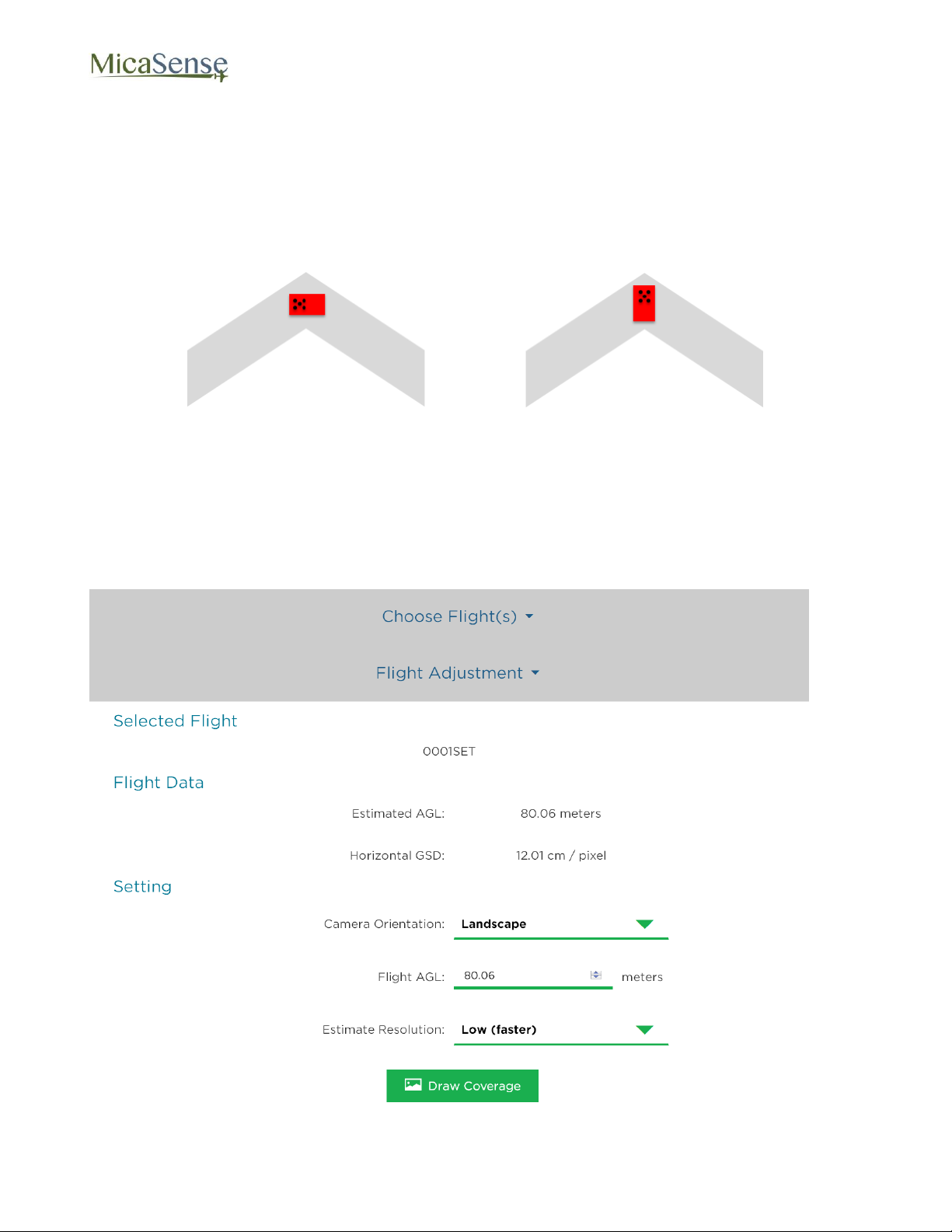
The Flight Adjustment tab should appear, and show a summary of its current estimation
settings. Camera Orientation indicates the directionality of the camera with respect to the
aircraft, as shown below.
Figure 7: Landscape Orientation on Left, Portrait Orientation on Right
The Flight AGL is estimated based on the GPS positions recorded for the images, with the
assumption that calibration panel pictures were taken near ground level, but if the estimate is
incorrect, you can manually enter the correct AGL.
The Estimate Resolution sets the quality of the output map. Low is sufficient for most
applications.
Figure 8: Confirm or Edit Coverage Estimate Settings
© 2015 MicaSense, Inc. Page 14 of 33
Page 15
RedEdge 3 User Manual Rev 06
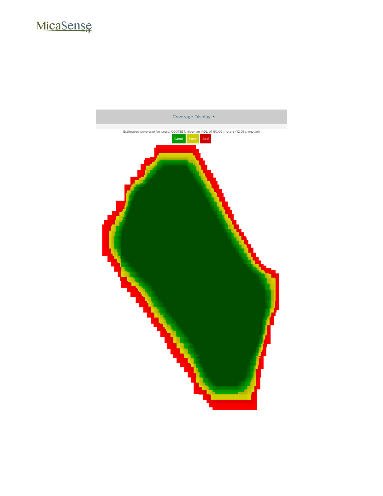
Clicking “Draw Coverage” will render the coverage estimate. The rendering time depends on
your device’s CPU, the size of the field, number of images, flight AGL, and quality setting, but
typically runs in under 30 seconds on a modern smart phone.
Finally, you will be presented with an estimate of your coverage. Any area that is dark green
has a high probability of correctly being processed in ATLAS. Areas that are yellow may
work, but likely will not. Red areas will almost certainly not process correctly.
Figure 9: Example of Good Field Coverage
Edges around the field will typically show as red or yellow. This is okay as long as the data
you are trying to collect is all contained within the dark green region.
© 2015 MicaSense, Inc. Page 15 of 33
Page 16
RedEdge 3 User Manual Rev 06
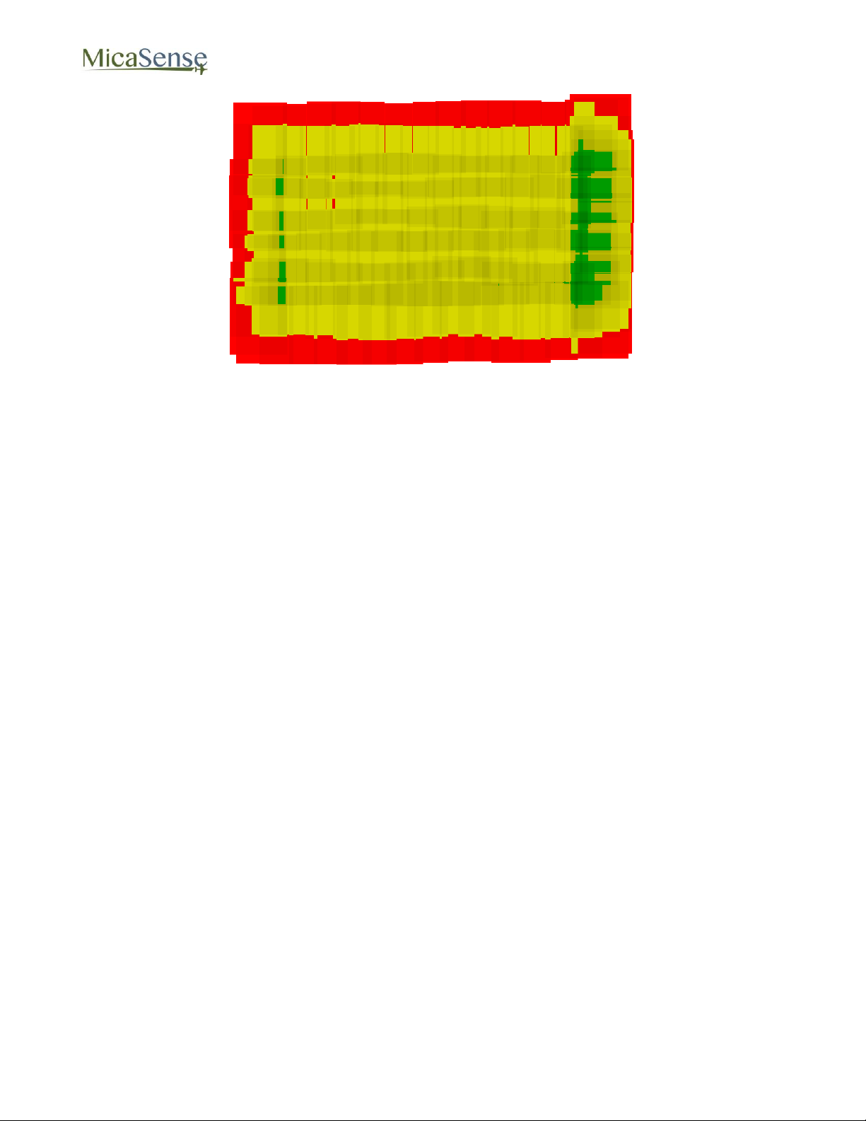
Figure 10: Example of Poor Field Coverage
If you discover your field coverage estimate is similar to the poor field coverage map shown
above, double check to make sure the Flight AGL is set correctly. If the Flight AGL is
incorrect, click back on the Flight Adjustment section, correct the Flight AGL, then click on
“Draw Coverage” again. If the Flight AGL is correct, your overlap settings may have be
wrong. You will need to capture more images of the field to ensure that post-processing will
be successful.
© 2015 MicaSense, Inc. Page 16 of 33
Page 17
RedEdge 3 User Manual Rev 06
3.5. Settings Page
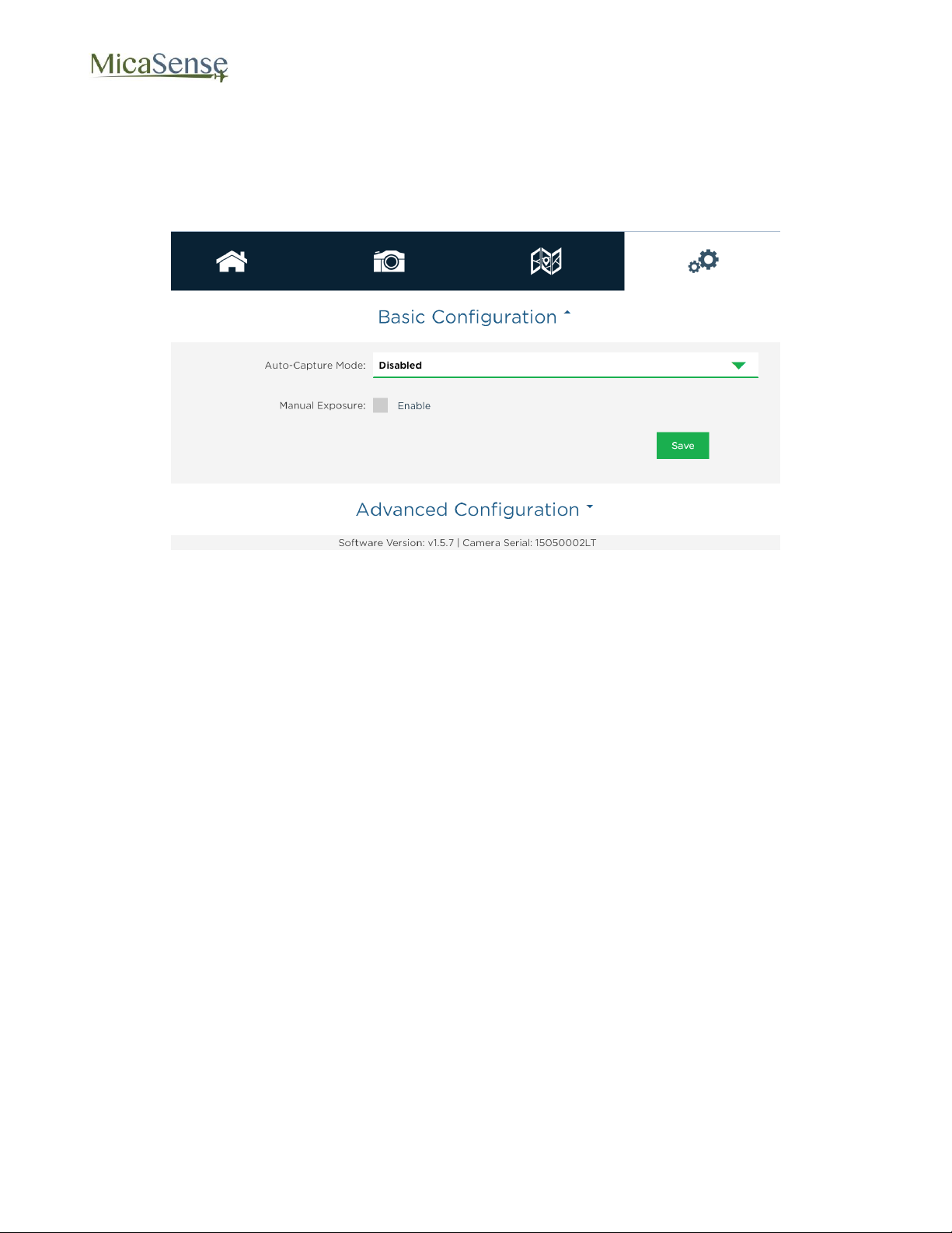
The settings page is used primarily to configure the Auto-Capture options for the camera. The
camera supports three methods of Auto-Capture: Timer mode, External Trigger mode, and
Overlap mode.
Figure 11: Settings Page
© 2015 MicaSense, Inc. Page 17 of 33
Page 18
RedEdge 3 User Manual Rev 06
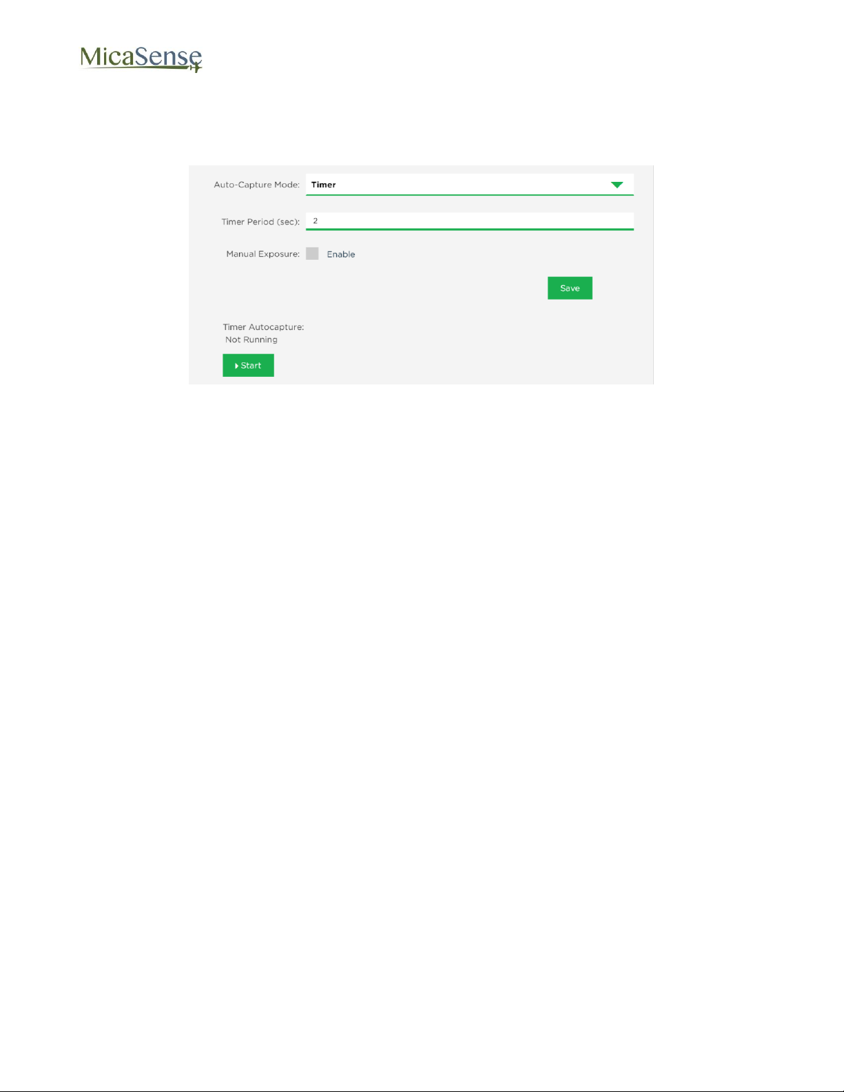
3.5.1. Timer Mode
1. Use the drop-down menu to select Auto-Capture Mode as “Timer”
Figure 12: Timer Mode
2. In the updated window, specify the interval between pictures to the desired setting. If
the timer interval is set to less than 1.0 seconds, the camera will capture as quickly as
it can (about once a second).
3. Press the “Save” button to save the Timer mode settings.
4. Press the Start button to begin capturing images at the desired interval rate.
5. Press the Stop button to stop capturing images
6. You can review and verify that images are being captured by selecting the Live View
page. Use the “Multi” setting in that page to verify that all five imagers are functioning
correctly and the images displayed are being updated at the interval rate selected.
© 2015 MicaSense, Inc. Page 18 of 33
Page 19
RedEdge 3 User Manual Rev 06
Setting
Meaning
Rising Edge
Camera will trigger on the rising edge of a pulse
Falling Edge
Camera will trigger on the falling edge of a pulse
Short PWM
Camera will trigger if PWM transitions from
longer than Threshold to shorter than Threshold
Long PWM
Camera will trigger if PWM transitions from
shorter than Threshold to longer than Threshold
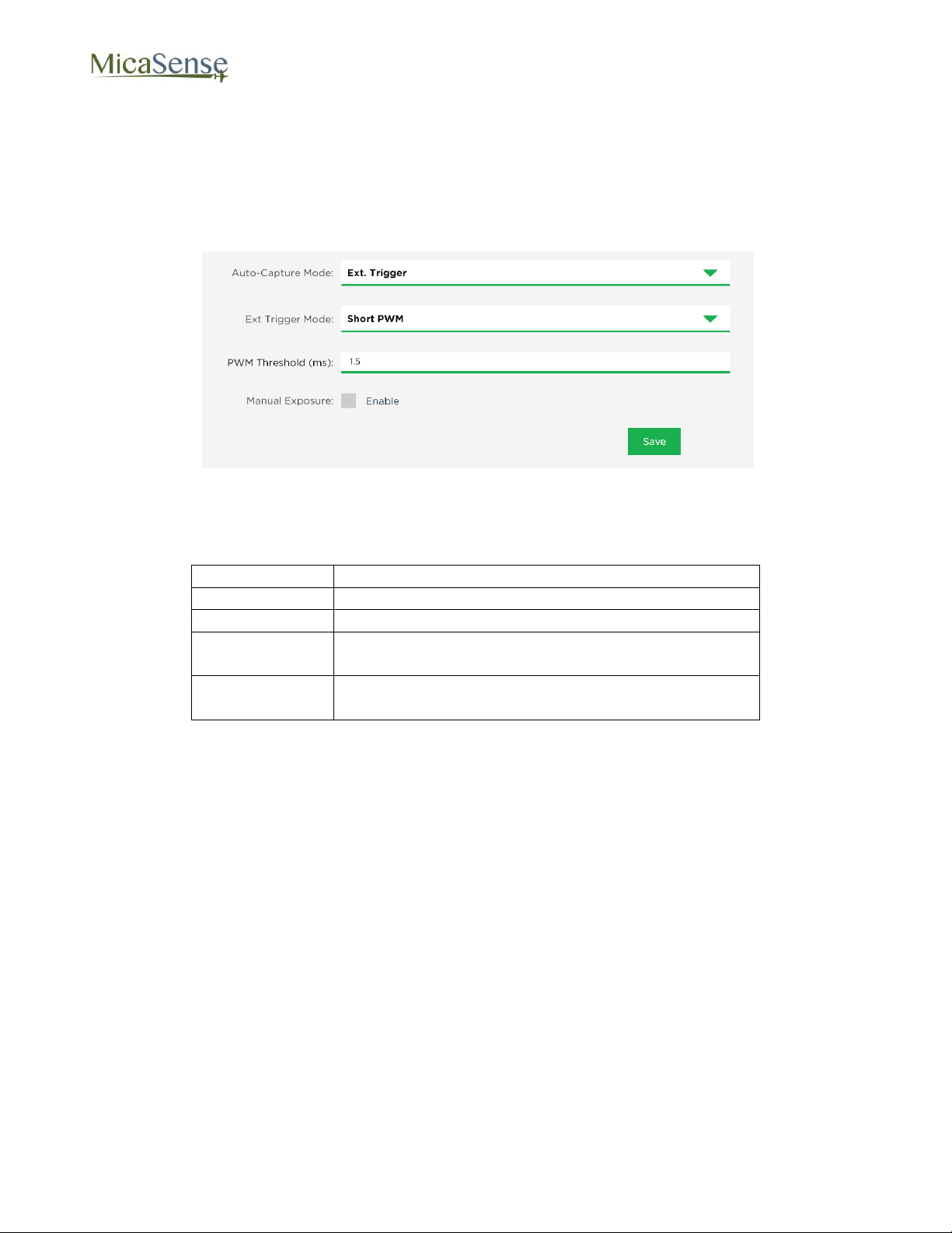
3.5.2. External Trigger Mode
1. For external trigger mode, you will need to connect a triggering signal to the camera –
refer to the RedEdge Integration Guide.
2. Use the drop-down menu to select Auto-Capture Mode as “Ext. Trigger”
Figure 13: External Trigger Mode
3. In the updated window, select the external trigger mode from the list. The settings are
as follows:
4. For PWM mode, enter the threshold PWM – note that this value is in ms (milliseconds), so the value is typically between 1.0 and 2.0.
5. Press the “Save” button to save the External Trigger mode settings.
6. Verify that the triggering is functioning by commanding a camera capture through the
host device and viewing the updated image in the Live View page.
© 2015 MicaSense, Inc. Page 19 of 33
Page 20
RedEdge 3 User Manual Rev 06
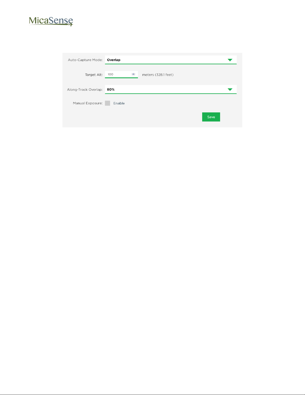
3.5.3. Overlap Mode:
1. Use the drop-down menu to select Auto-Capture Mode as “Overlap”
Figure 14: Overlap Mode
2. In the updated window, select the Target Alt to be the altitude AGL at which the aircraft
will be operating during the mapping mission. Note that this is specified as AGL
(Above Ground Level) altitude.
3. Specify the Along-Track Overlap in % of image that is common between one image
and the adjacent one.
4. Press the “Save” button to confirm the settings.
5. When the aircraft reaches the target altitude minus 50 meters, it will initiate taking
captures and will take a capture if the distance traveled is detected to be greater than
the required distance as specified in the % overlap setting.
6. When the measured altitude is lower than target altitude minus 50 meters, the camera
stops taking captures.
© 2015 MicaSense, Inc. Page 20 of 33
Page 21
RedEdge 3 User Manual Rev 06
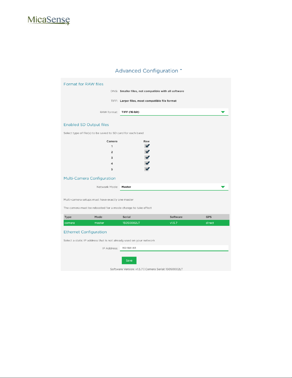
3.5.4. Advanced Configuration:
The Advanced Configuration menu provides controls for managing file storage for RedEdge,
as well as Ethernet and Multi-Camera configurations.
Figure 15: Advanced Configuration
You can specify the RAW Format to be either 12-bit DNG or 16-bit TIFF. The 12-bit DNG
format will produce files that are 25% smaller in size than 16-bit TIFF files.
The menu also enables the user to specify which bands to capture to SD card. The default of
capturing all 5 bands is the recommended setting. However, if only a subset of the bands are
desired, the other bands can be de-selected. Click “Save” button to commit any changes.
© 2015 MicaSense, Inc. Page 21 of 33
Page 22

RedEdge 3 User Manual Rev 06
The Network Mode is only relevant if you have more than one RedEdge camera. The table
below the setting indicates the settings of all other networked cameras. In addition to
configuring a single master, all of the camera software versions should match. After changing
the camera’s network mode, you must click “Save”, and then reboot the camera in order of
the new setting to take effect.
Ethernet Configuration allows you to assign a different IP address to the camera. Note that
this will NOT configure the WiFi address, which will always be 192.168.10.254.
3.5.5. Manual Exposure:
Manual exposure checkbox enables manual control of the exposure and gain of the camera,
with settings available in the Live View Page. This is an advanced operation option and
should normally NOT be enabled.
© 2015 MicaSense, Inc. Page 22 of 33
Page 23
RedEdge 3 User Manual Rev 06
Item
Value
Lens Focal Length
5.5 mm
Lens Field of View
47.2 deg. HFOV
Imager Size
4.8 mm x 3.6 mm
Imager Resolution
1280 x 960 pixels
16-bit TIFF
Format
16-bit TIFF
Format
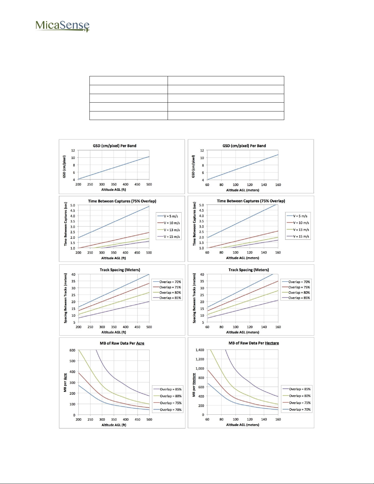
4. Mapping Operations
For proper overlap settings during mission planning, the following information may be
required:
Figure 16 shows parameters for mission planning and file storage planning.
© 2015 MicaSense, Inc. Page 23 of 33
Figure 16: Mission Planning Information
Page 24
RedEdge 3 User Manual Rev 06
5. External Connections
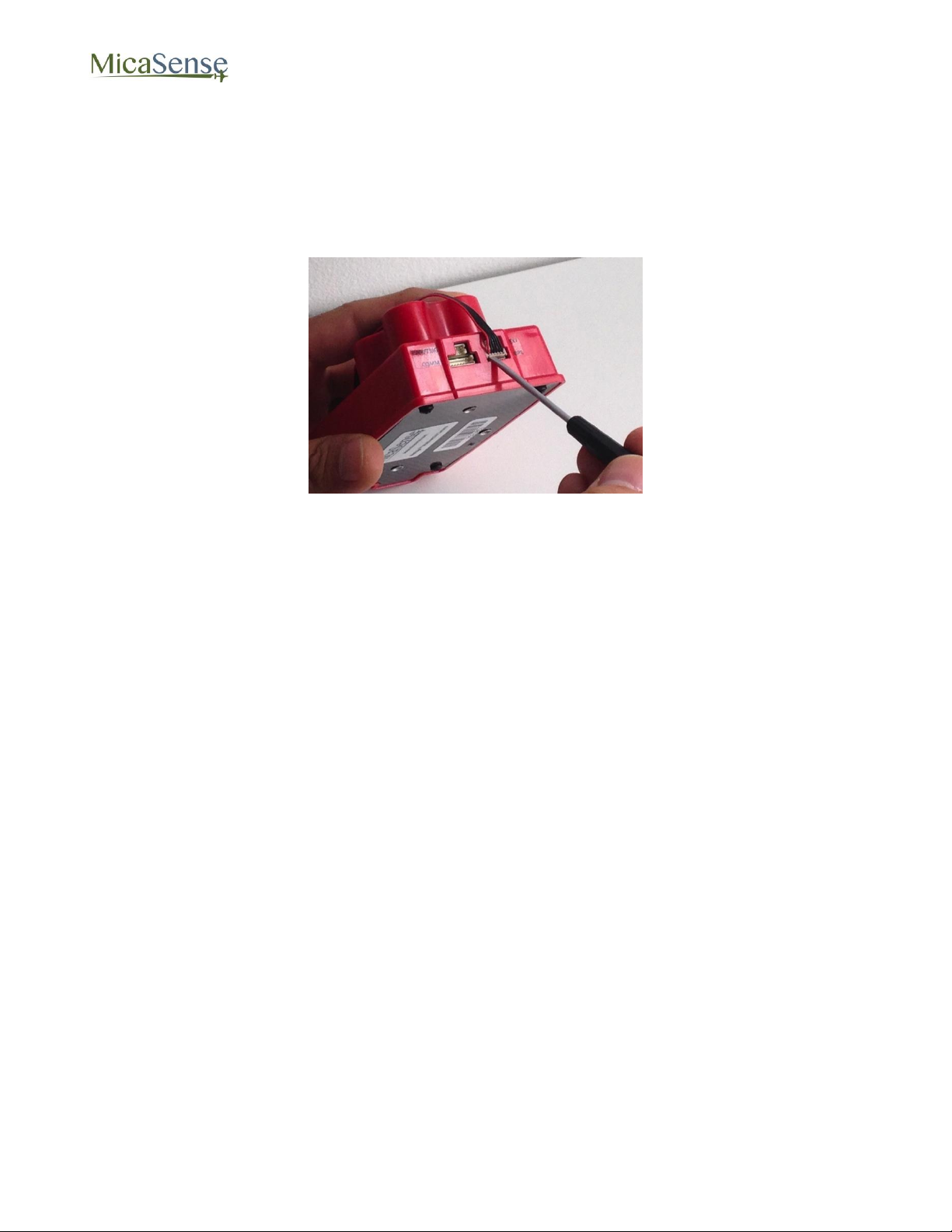
Refer to RedEdge Integration Guide for details on connectors, pin-outs, and voltage
specifications. When removing the cables that plug into these connectors, use a small
flathead screwdriver to pry off the connector at the plastic interface. Do not pull on the wires
to unplug these connectors.
Figure 17: Removal of Connectors Using Small Flathead Screwdriver
© 2015 MicaSense, Inc. Page 24 of 33
Page 25
RedEdge 3 User Manual Rev 06
Format
Average File Size
12-Bit DNG
1.8 MB per file (5 files per capture)
16-Bit TIFF
2.5 MB per file (5 files per capture)
6. File Storage
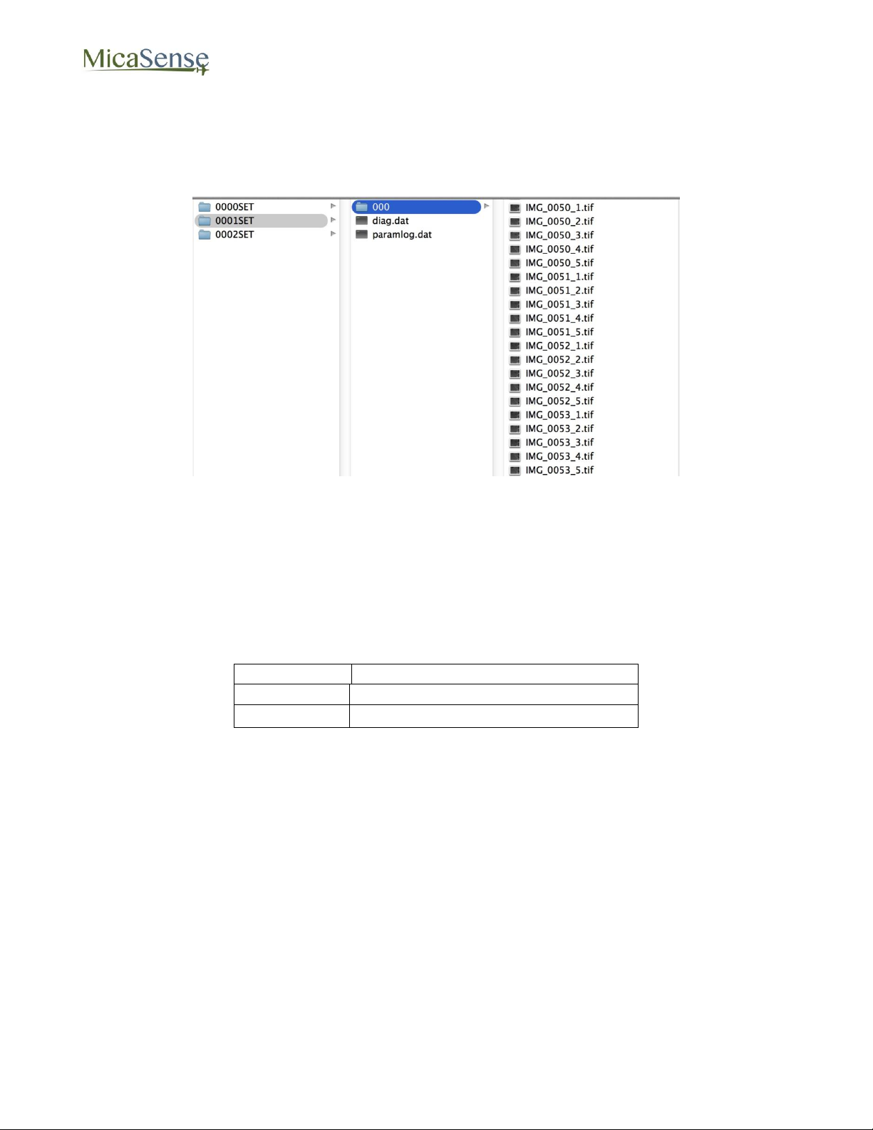
The RedEdge camera stores files in the SD card in a folder structure. A new folder is created
for each time the camera is powered up.
Figure 18: File Structure of SD Card
Within each folder, a subfolder with the images themselves is created. If more than 999
images are stored, a second image folder is created (“000” and “001” for instance). Two log
files are also created.
Within each subfolder, a group of 5 files is created for each image capture (5 TIFF files). The
suffix at the end of each file indicates the imager number (see Figure 4), from 1 through 5.
The TIFF files are 12-bit resolution stored in either 12-bit DNG RAW format or 16-bit TIFF
RAW format depending on the setting (see Section 3.5.4). The resolution is 1280x960 pixels.
Metadata tags are embedded for each file in standard format.
© 2015 MicaSense, Inc. Page 25 of 33
Page 26
RedEdge 3 User Manual Rev 06
7. Data Collection Recommendations
In order to accurately process data captured with MicaSense’s RedEdge camera, the
following recommended guidelines should be observed during collection of the data:
1. A GPS receiver module or other source of GPS information should be connected to
the RedEdge camera and a valid GPS fix should be verified prior to flight.
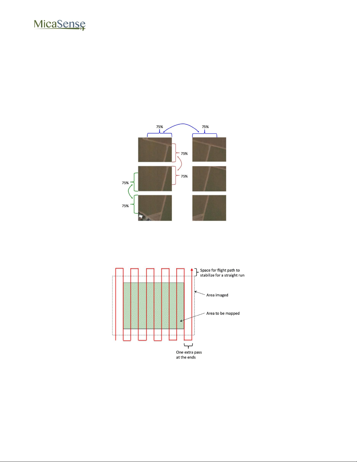
2. A minimum cross-track and along-track overlap of at least 75% is recommended.
Figure 19: Overlap Recommendations
3. At least one track of the flight area should be outside all edges of the field to be
mapped (to ensure that there is data going all the way to the edges of the field)
Figure 20: Coverage Area for Mapping a Field
4. View of camera should be within 10 degrees of Nadir (within 10 degrees of straight
down with respect to the Earth) during the mapping portions of the flight. Use of a
nadir-pointing gimbal for the camera is highly recommended.
© 2015 MicaSense, Inc. Page 26 of 33
Page 27
RedEdge 3 User Manual Rev 06
NOTE
The camera applies a different gain/exposure optimization method for panel
captures versus captures taken in flight. You should capture images of the panel
using the Capture button on the Wi-Fi interface or by pressing the physical
capture button on the camera.
Do not use Timer, Overlap, or External Trigger modes for panel captures.
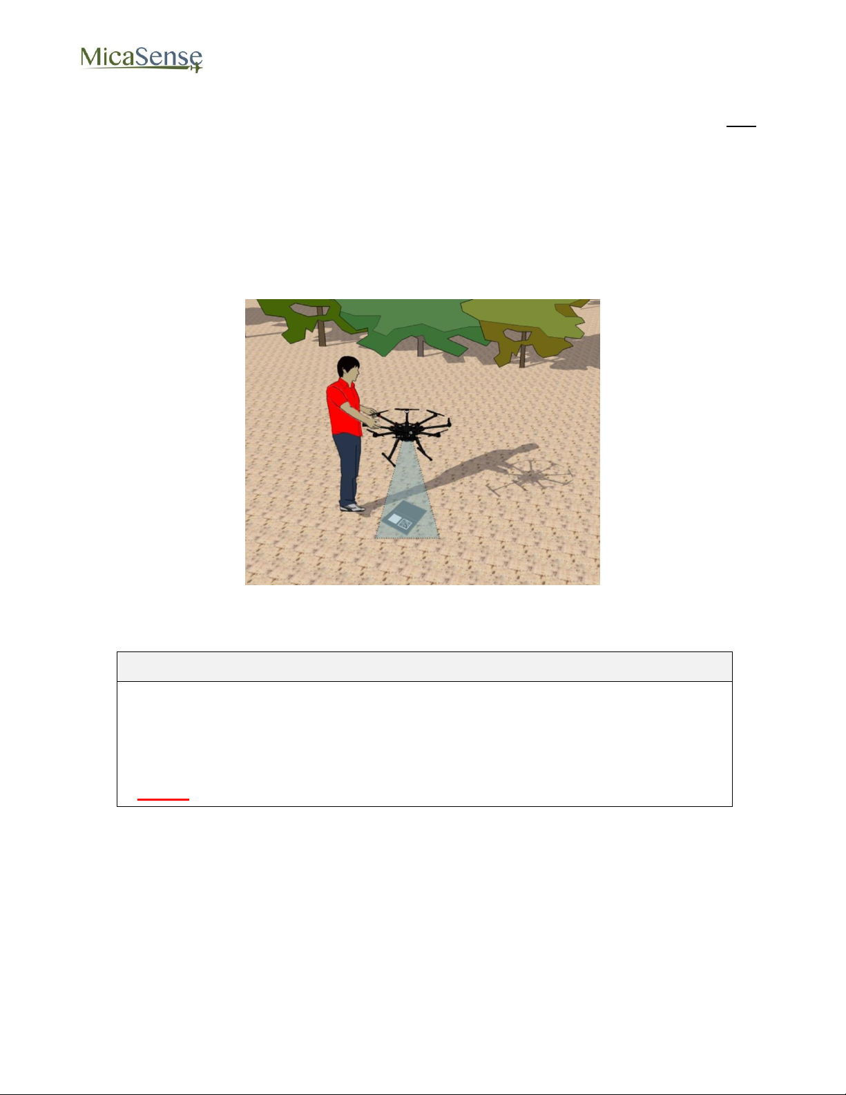
5. For accurate reflectance data, pictures of a calibrated reflectance panel (Spectralon or
similar) should be captured from directly overhead the panel immediately before and
immediately after each flight.
When imaging the reflectance panel, place the panel flat on the ground and ensure
that it is not shadowed by anything, that it is receiving direct light from the sun or sky,
and that the angle of view from the camera to the panel is as perpendicular as
possible (without shadowing). Avoid having the sun reflect off any surface and hit the
panel. It’s best to place your shadow just to the left or right of the panel (see below for
recommended position).
Figure 21: Capturing Reflectance Panel Image
© 2015 MicaSense, Inc. Page 27 of 33
Page 28
RedEdge 3 User Manual Rev 06
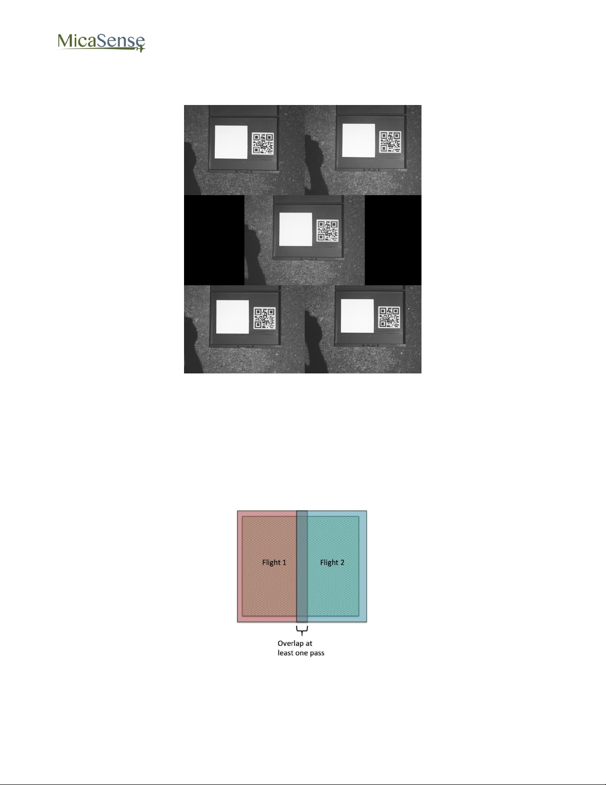
The panel should take approximately half of the view of the camera. If using a
MicaSense panel, ensure that the QR code is visible in the image.
Figure 22: Example of Panel Capture
6. It is recommended to gather data during weather that provides consistent illumination
(avoid days with clouds that move in and out and cast changing shadows on the
ground).
7. For best results, data collection should be done within 2.5 hours of local solar noon.
8. For vineyards and plants with significant height above the ground, optimal results are
obtained when the flight path is perpendicular to the rows if possible.
9. If a field needs to be flow in more than one flight, the coverage regions for each flight
should overlap:
Figure 23: Multiple Flights for the Same Field Should Overlap
© 2015 MicaSense, Inc. Page 28 of 33
Page 29
RedEdge 3 User Manual Rev 06
SD card installed
Power cable connected
GPS for camera connected and connectors secured
Lenses are clean, not scratched, clear of obstructions
If using external trigger: trigger cable connected to triggering source
If using gimbal: gimbal is functional and operating properly
Apply power or manually turn ON camera - verify boot-up complete (blinking Status LED)
Connect to camera using WiFi-capable device
Connect to “rededgeXXXXXX” WiFi network (password = “micasense”)
Open web browser and point to 192.168.10.254
Select Home Page
Verify voltage is good (green background, 4.0 to 5.5 V DC)
Verify free space on SD card sufficient for mission
Verify GPS date and time are correct
Wait for GPS fix
Confirm GPS fix (> 3 Satellites Used)
Confirm green blinking Status LED
Configure auto-capture mode - press “Save” after all changes
Select Live View Page
Point camera at reflectance panel (make sure camera has GPS fix)
Panel placed on ground, far from any obstructions
Panel fills about half the camera’s field of view
Camera pointed as perpendicular to panel as possible
No shadows on panel
Direct sunlight illumination on panel (no reflected lighting)
Press “Capture” button on Live View Page and verify image captured correctly
Take at least two captures
Panel captures should ONLY be commanded from the Live View Page interface
or by pressing the physical trigger button. Do not use Timer, Overlap, or External
Trigger mode for capturing panel images.
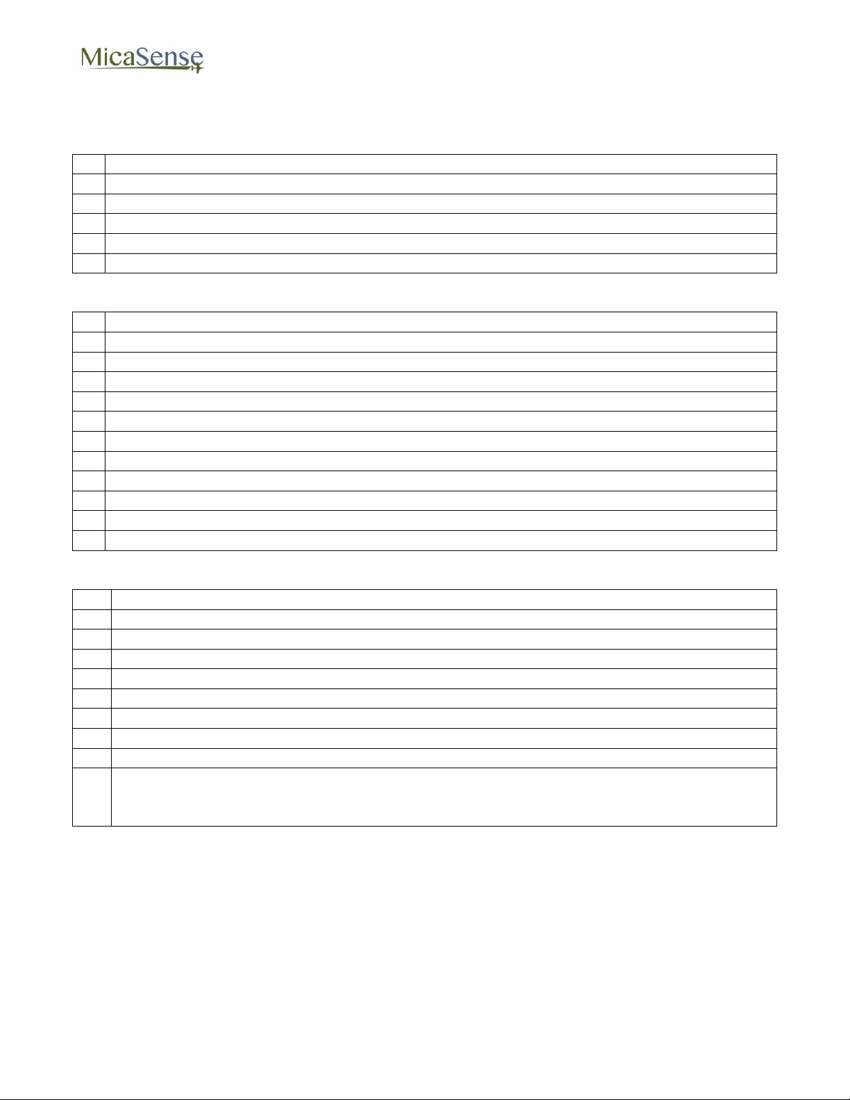
8. Checklist for Operation
1. Before Power-Up
2. Camera Power-On and Configuration
3. Before-Flight Reflectance Panel Images
© 2015 MicaSense, Inc. Page 29 of 33
Page 30
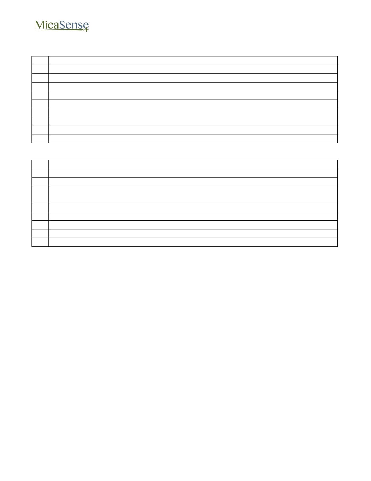
4. Immediately Before Flight
Confirm green Status LED in front of camera
Verify auto-capture settings
If using Timer mode:
When ready to launch, press "Start” in Settings Page
Go to Live View page and verify capture at desired interval
If using Overlap mode:
When ready to launch, press "Start” in Settings Page
If using External Trigger mode:
Force a manual trigger capture using aircraft’s controller
In Live View Page, verify image captured
Connect to camera using WiFi capable device
In Home Page, verify SD card free space:
If SD card is full it is likely some pictures were not captured
If desired, download KML file from Coverage Page and view in Google Earth or GIS
application
If using Timer auto-capture mode:
In Settings Page, click “Stop” button
Obtain after-flight reflectance panel images
Same process as before-flight reflectance panel images
Power camera OFF (hold power button for at least 4 seconds)
5. After Flight
RedEdge 3 User Manual Rev 06
© 2015 MicaSense, Inc. Page 30 of 33
Page 31
RedEdge 3 User Manual Rev 06
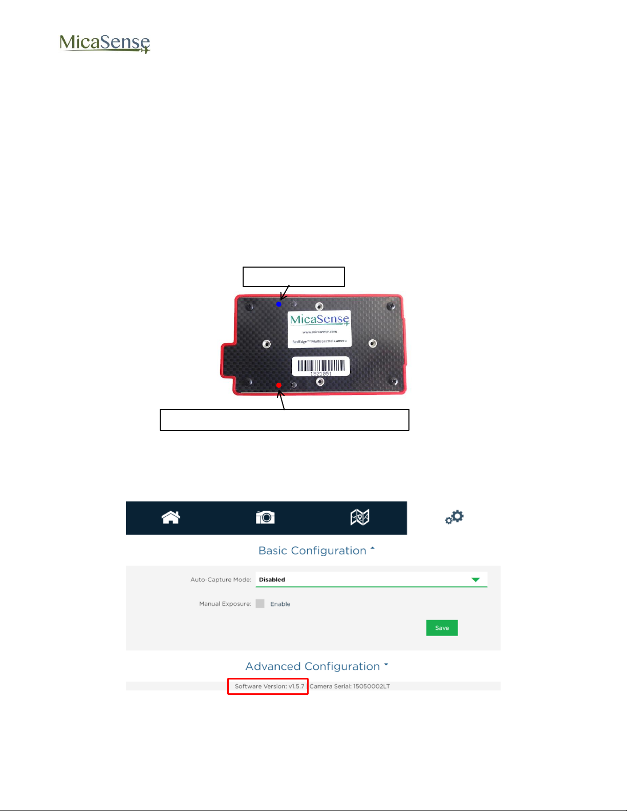
Power LED (Blue)
Status LED (Red) – Flashes During Programming
9. Firmware Update
The firmware in the RedEdge camera can be easily updated following these steps:
1. Copy the rededge.bin file to the root folder of any SD card (the SD card that came
with the camera is recommended).
2. With camera powered OFF, insert SD card into camera.
3. Provide a source of power (5.0 Volts DC at 5 Watts) to the camera and power camera
ON if it doesn’t power on automatically. The red light on the back of the camera will
immediately start to rapidly flash, indicating that the camera is installing the firmware.
When the red light stops flashing, the installation process is complete (should be less
than 30 seconds).
4. The camera should then boot up normally, and the light in the front will flash at
approximately a once per second interval.
5. Verify the software was updated by checking the “Settings” page on the camera’s web
page. The firmware version number is shown at the bottom of the page.
6. Remove the SD card and delete the bin file (otherwise each time you power up the
camera, it will install the firmware).
© 2015 MicaSense, Inc. Page 31 of 33
Page 32
10. Specifications
Basic Specifications
Weight
150 g
Dimensions
12.1 cm x 6.6 cm x 4.6 cm (4.8” x 2.6” x 1.8”)
Power
5.0 V DC, 4 W nominal
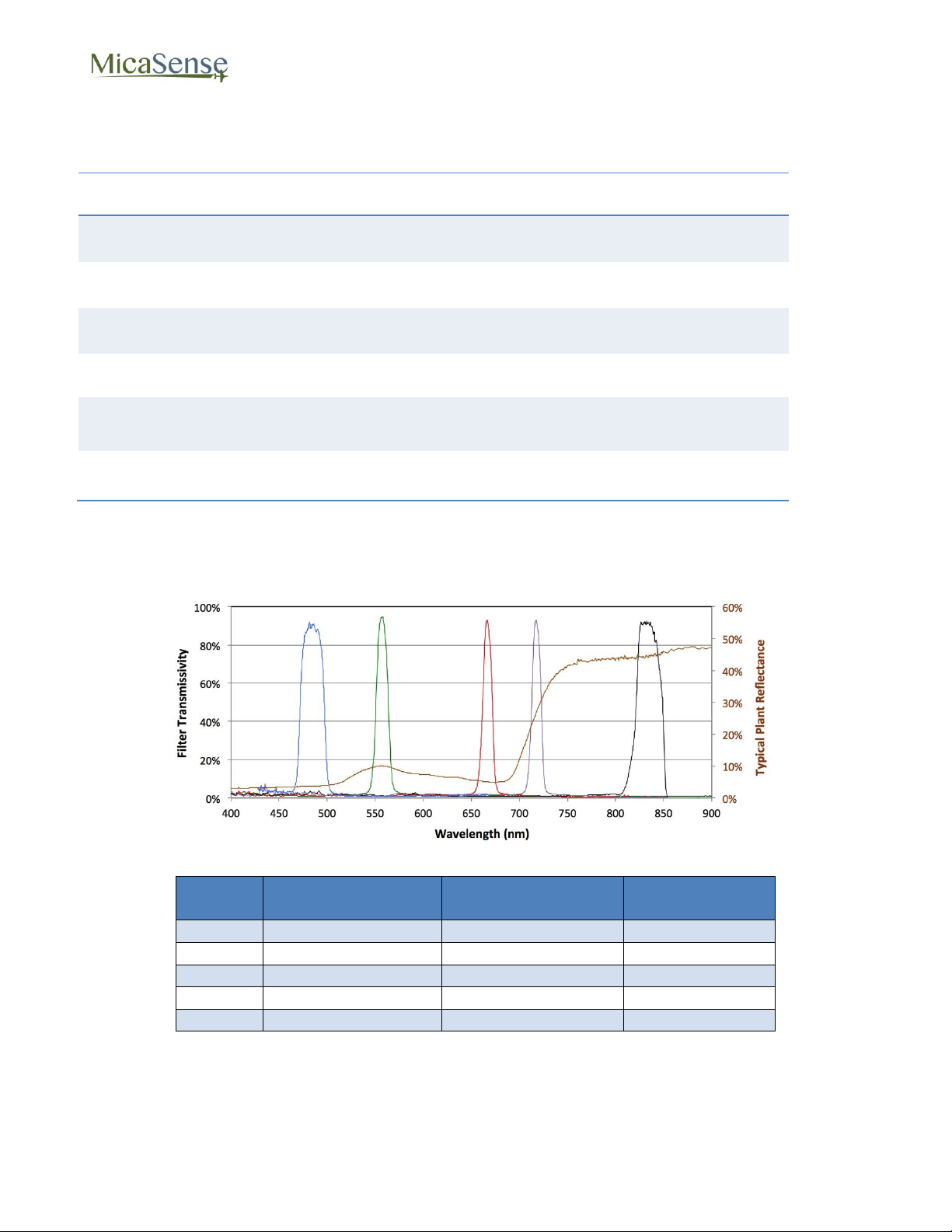
Spectral Bands
Narrowband: Blue, Green, Red, Red Edge, Near IR
Ground Sample
Distance
8.2 cm/pixel (per band) at 120 m (400 ft.) AGL
Capture Speed
1 capture per second (all bands), 12-bit RAW
Band
Number
Band Name
Center
Wavelength (nm)
Bandwidth
FWHM (nm)
1
Blue
475
20 2 Green
560
20 3 Red
668
10
4
Near IR
840
40
5
Red Edge
717
10
Spectral Bands
RedEdge 3 User Manual Rev 06
© 2015 MicaSense, Inc. Page 32 of 33
Page 33

RedEdge 3 User Manual Rev 06
MicaSense RedEdge™ 3 Multispectral Camera
User Manual
Rev 06 – October 2015
MicaSense, Inc.
1055 N 38TH ST
Seattle WA 98103
The contents of this manual are subject to change without notice
MicaSense, Inc. assumes no liability for incidental or consequential damages arising
from the use of this product, and any claims by a third party.
Copying of the contents of this manual, in whole or in part, as well as the scanner
applications is prohibited under the copyright law.
© 2015 MicaSense, Inc. Page 33 of 33
 Loading...