

Page 1
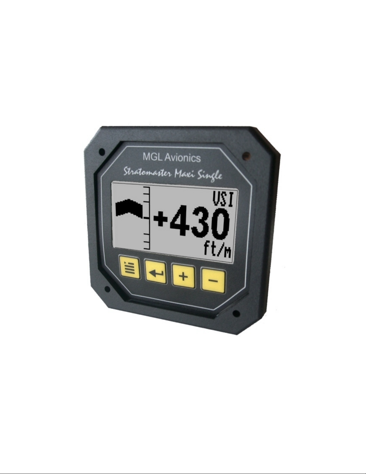
Stratomaster Maxi Single
VSI-2
Wide range digital VSI
The VSI-2 vertical speed indicator is a 3.5” instrument able to show true, altitude compensated
vertical speed in either feet/minute or meters/second.
Offering a digital readout with a wide range from +/-20 ft/min to as high as +/-10.000 ft/min, it also
offers a logarithmic analog display with a +/-2000 ft range.
The VSI-2 can be calibrated by the user once the instrument has been installed in the aircraft.
Page 2
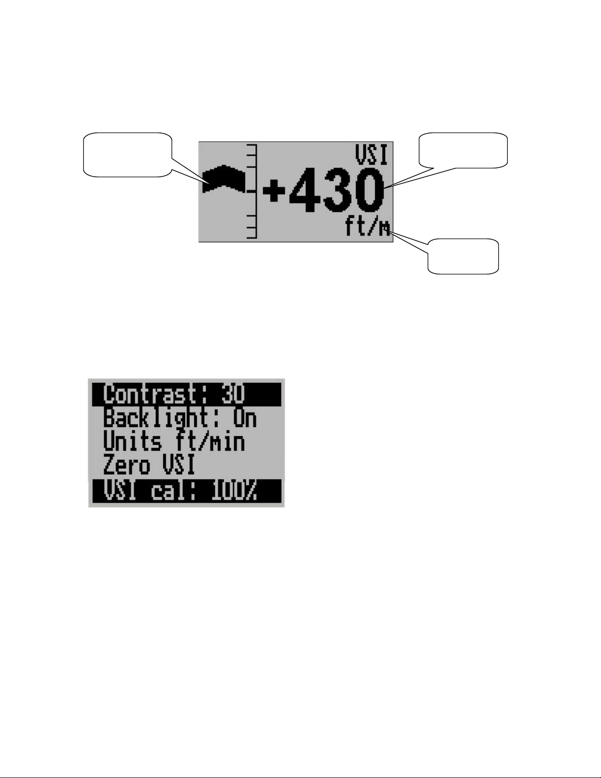
The main display
(log
Analog VSI
graph
arithmic)
Digital VSI
readout
Units of
measure
Setting up the VSI-2
Press the Menu key to enter the menu. You can move forward and backwards in the menu by
using the + and – keys. To change or select a menu item, move the highlight to the desired item
and then press the Select key. To end an edit or function, press the Menu key again.
To exit the menu and continue normal operation, press Menu again.
Contrast …
This function allows you to change the display contrast to your liking. You can select values from
about 20 to 45. (can vary depending on display type).
Backlight …
This function allows you to switch the display backlight on or off.
Page 3

Units …
Select if you want your VSI readout in feet/minute (ft/m) or meters/second (m/s). Note:
meters/second will be shown with two decimals, example: “1.23”.
Zero VSI
This function is used to set your VSI to read exactly 0ft/min. This is similar to setting the needle
on a mechanical VSI to point to zero by turning the adjustment knob on such a VSI.
The electronic VSI generally has much less drift compared to a mechanical VSI and this function
will only be used very occasionally. Ensure that you perform this function when no pressure
changes due to wind or other reasons are occurring.
VSI cal
This is a technical function that is used to calibrate your VSI to read exact rates of climb or
decent. This function works as a percentage of initial reading. The default setting for this function
is 100%. Increasing this value increases the VSI reading and decreasing the value decreases the
reading.
Suggested calibration method.
After you have installed the instrument, perform a calibration flight. This should be done in very
calm conditions. Turbulence and thermal activity will make accurate calibration impossible. Many
areas have ideal conditions during early mornings or late afternoons.
Place the instrument in “feet” units mode for ease of calibration.
Take your aircraft to a few thousand feet above ground and start a glide with a low power setting.
Take a stopwatch and when the glide is stable (stable VSI reading) start the stopwatch. Take
note of your altimeter reading at the same time.
Continue the stable glide for one minute exactly. After the minute has finished, take another
reading of your altimeter.
Example:
VSI reading during stable glide: -400 ft/min
Start altitude: 2500 ft.
End altitude: 2050 ft.
In the above example the VSI is under reading by about 12%. Set your VSI calibration to 112% to
cancel out the error.
ADC
This function is for technical personal. It is not used for ordinary operation of the unit. This
function can be accessed if the instrument is switched on and both “+” and “-“ keys are held at the
same time.
Page 4

Technical specifications:
Display temperature range (operational): -20 to +80 degrees C
Supply voltage: +8 to +18V. +24/28V with optional pre regulator.
Supply current: 35mA/70mA (backlight off/on)
Digital VSI range: +/-20ft/m to +/-10.000ft/m
Digital VSI resolution: 10ft.
Analog VSI range: +/-2000 ft/m, logarithmic scale.
Measurement accuracy: +/- 2%, relative to calibration.
Weight: 90 grams.
Warranty:
MGL avionics warrants their products for a period of one year from date of purchase against
faulty workmanship. Warranty is limited to the replacement of faulty components and includes the
cost of labor. Shipping costs are for the account of the purchaser.
Note for operation on supplies with inductive loads:
Any operation of electronic instrumentation on power supplies that are subject to high voltages
caused by operation of inductive loads (starter motors, solenoids, relays) are required to be fitted
with suitable protection.
All Smart Singles are guaranteed to withstand temporary over voltage up to 40V without
additional protection. We recommend that measures are taken to prevent voltage transients in
excess of this limit.
MGL Avionics recommends the fitment of a fuse in line with a 33V transorb (available from MGL
Avionics at low cost) to protect electronic instruments, radios and intercom systems. Only one
such arrangement is required for a cluster of instruments.
Please note that product warranty excludes damages caused by unprotected, unsuitable or
incorrectly wired electrical supplies.
This instrument is not certified by the FAA. Fitting of this instrument to certified aircraft is subject
to the rules and conditions pertaining to such in your country. Please check with your local
aviation authorities if in doubt.
This instrument is intended for ultralight, microlight, homebuilt and experimental aircraft.
Operation of this instrument is the sole responsibility of the pilot in command (PIC) of the aircraft.
This person must be proficient and carry a valid and relevant pilots license. This person has to
make him/herself familiar with the operation of this instrument and the effect of any possible
failure or malfunction. Under no circumstances does the manufacturer condone usage of this
instrument for IFR flights.
Page 5
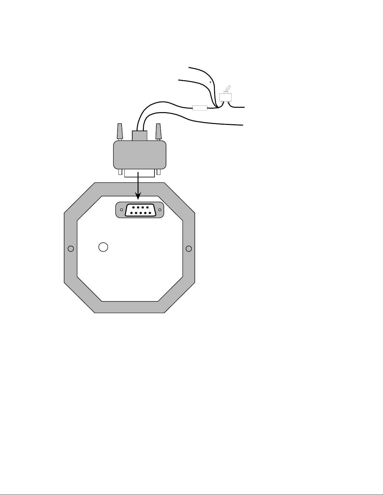
Installing the VSI-2
To other instruments
Connect static port
to suitable static line
on aircraft.
Note: leaving this port
unconnected may lead to
VSI errors as cabin
pressure chages due to
airflow or other factors
Static port
Cannon D-9
connector
RED
Fuse
BLACK
Suggested fuse rating:
1.0 A slow blow
Power
switch
Positive supply
(+12V from battery)
Negative supply
(airframe ground)
Installing the VSI-2 is quite simple.
Connect the supply terminals to your aircraft’s power supply (you need a dropping resistor or preregulator for 24/28V systems).
Install suitable power supply protection if you have a supply that can contain large voltage
transients such as can be created by starter motors and solenoids.
Ensure that the supply voltage will not drop below 8V during operation as this may result in
incorrect VSI readings.
Connect the static port to a suitable static air pressure line. If you have a slow aircraft or an
aircraft were the internal cabin pressure does not change during flight and is equivalent to the
outside air pressure you may find that it is not required to connect a static port.
For installations in typical ultralight aircraft pods, be aware of possible pressure changes inside
the pod during flight caused by ram air or suction effects. This may lead to a false indication of
vertical speed. Often these effects are dependent on the current angle of attack of the airflow
around your pod. You will need to install a suitable static port in these cases.
 Loading...