


Iefis
Table of contents
 Loading...
IEFIS panel installation manual
This document details hardware installation and system configuration of an iEFIS panel.
This document is applicable for the following iEFIS panels and iBOX devices:
IEFIS Discovery – 7” panel.
IEFIS Explorer – 8.5” panel.
IEFIS Challenger – 10.4” panel.
IBOX V1 – full function EFIS interface unit
IBOX V2 – low cost EFIS interface unit
Preliminary document
Document date: 5 July 2012
Page 1

Table of Contents
General........................................................................................................................................5
Example rear panel (Explorer EFIS)...........................................................................................6
Example system design..............................................................................................................7
The iBOX installation...................................................................................................................7
The iEFIS LAN............................................................................................................................8
IEFIS LAN terms.........................................................................................................................8
Primary LAN............................................................................................................................8
Secondary LAN.......................................................................................................................9
Active panel............................................................................................................................9
Inactive panel(s)......................................................................................................................9
Assigning iEFIS panel addresses...............................................................................................9
Configuration of the iEFIS system............................................................................................10
Navigating the menus................................................................................................................11
Configuring a system for the first time.......................................................................................11
The “system setup” menu.........................................................................................................13
Broadcast/Accept functions and setup.................................................................................13
Time/Date/Hobbs setup .......................................................................................................14
System units setup................................................................................................................14
System operation setup........................................................................................................14
Engine monitoring setup.......................................................................................................14
Flight Instruments setup.......................................................................................................14
Analog/Digital inputs setup...................................................................................................14
AGL and Flap warning setup................................................................................................15
Enable AOA calibration functions.........................................................................................15
Setup horizon sensor............................................................................................................15
Setup Compass sensor........................................................................................................15
Rotor craft instruments setup................................................................................................15
Setup Navigation...................................................................................................................15
Setup GPS and NMEA port operation..................................................................................16
Setup HSI/GSI Indicators......................................................................................................16
GLS/GVOR setup.................................................................................................................16
Terrain warning setup...........................................................................................................16
Traffic monitoring setup........................................................................................................16
Checklist functions................................................................................................................16
Voltage/Current setup .........................................................................................................17
Setup Autopilot......................................................................................................................17
Autopilot servo tests and checks..........................................................................................17
Serial port routing and allocations........................................................................................17
ADSB setup menu................................................................................................................17
Transponder setup menu......................................................................................................18
COM radio setup ..................................................................................................................18
ARINC setup.........................................................................................................................19
ARINC TX label setup...........................................................................................................19
Flap, pitch and roll trim indicator and control setup..............................................................19
Page 2

Video inputs setup menu......................................................................................................19
Calibrate Touch Screen.........................................................................................................19
Equipment Enables...............................................................................................................19
Standard System selections.................................................................................................20
IBOX functions and sensor setup.........................................................................................20
System Basic setup functions...............................................................................................20
Engine monitoring setup...........................................................................................................22
RPM 1 and RPM 2 setup menu............................................................................................23
Engine HP calculation setup.................................................................................................23
TC Channel scan setup........................................................................................................24
Using universal TC channels:...........................................................................................25
EGT setup menu...................................................................................................................26
CHT setup menu...................................................................................................................26
Oil temperature setup menu.................................................................................................27
Oil pressure setup menu.......................................................................................................27
Coolant temperature setup menu.........................................................................................28
AUX1 temperature setup menu............................................................................................28
AUX2 temperature setup menu............................................................................................28
Manifold pressure setup menu.............................................................................................28
Temp/TC 1,2,3,4 setup.........................................................................................................29
Current sensor setup menu..................................................................................................30
Fuel related setup ....................................................................................................................31
Fuel range/endurance setup.................................................................................................31
Fuel level sender damping....................................................................................................31
Setup RDAC 1,2,3,4 fuel probes and senders.....................................................................31
Fuel flow 1,2 setup menu......................................................................................................32
Fuel tank setup menu...........................................................................................................33
Physical tank multi point calibration......................................................................................34
Flight instruments setup............................................................................................................35
Airspeed indicator setup.......................................................................................................35
ARINC setup.............................................................................................................................37
ARINC transmitted labels.....................................................................................................38
Flap indicator and control setup................................................................................................39
Pitch trim indicator and control..................................................................................................41
Roll trim indicator and control...................................................................................................42
IBOX functions and sensor setup.............................................................................................44
Zero analog navigation inputs...............................................................................................44
Zero ASI and AOA sensors...................................................................................................44
ASI calibration.......................................................................................................................45
Altimeter calibration factor....................................................................................................45
VSI Calibration factor............................................................................................................45
Ambient temp calibration......................................................................................................45
ALT/ASI Factory calibration..................................................................................................45
Load iBOX firmware from SD/MMC card..............................................................................45
Notes on changing settings in the iBOX...............................................................................46
Serial port routing/Allocations...................................................................................................47
Flight data recording setup.......................................................................................................48
Page 3

Checklist setup..........................................................................................................................49
Sample wiring diagrams............................................................................................................51
12V or 24V systems with AvioGuard TM..................................................................................54
Example iBOX ARINC connections..........................................................................................55
Example iBOX RS232 wiring....................................................................................................56
Page 4

General
IEFIS consists of one or more panels, one or two iBOX units as well as sensors and control
interfaces as required.
As of writing of this document the following MGL devices are compatible with the iEFIS
system:
Up to 8 panels may be connected in a single system
iEFIS Discovery: 7” screen size panel
iEFIS Explorer: 8.5” screen size panel
iEFIS Challenger: 10.4” screen size panel
iBOX V1: Full feature, central interface for an iEFIS system (up to 2 units)
SP-6 CAN: Compass/Magnetometer (up to 2 units)
SP-7 CAN: AHRS (up to 4 units)
SP-8 CAN: SP-6 and SP-7 in one housing (up to 4 units)
SP-9 CAN: High grade AHRS (up to 4 units)
SP-10 CAN: Flap, trim and gear controller (up to 6 units, up to 2 functions/unit, 6 functions
max)
RDAC XF: Engine monitoring interface (up to 4 units/engines)
RDAC CAN: ECU interface (up to 2 units/engines)
MGL V6: COM radio (including full remote control)
MGL V10: COM radio (including full remote control)
MGL ECB system (up to 4 units, 48 breakers)
MGL iEFIS wireless node (one per system)
MGL iEFIS wired node (up to 8 – including iEFIS panels)
MGL Autopilot servos (Bank, Pitch, Yaw)
MGL/Garrecht mode-s transponder
The following third party products are compatible with the iEFIS system:
Garmin SL40 COM radio
Garmin SL30 NAV/COM radio
Garmin G430W and newer GPS/NAV/COM systems
Sandia aerospace STX-165R mode-c transponder
Vertical power VPX
Traffic systems compatible with ARINC 735 (TIS, TCAS, ADSB with TIS output)
Traffic systems: NAVWorx ADSB, FLARM, XRX PCAS
Transponders requiring greycode (gillman code) altitude encoder can be connected, using the
iBOX altimeter as alticoder source.
Older navigation systems (VOR/ILS) using +/-150mV differential outputs to drive indicators
can be connected as navigation source.
External autopilots can be connected to NMEA (RS232 port 6 on the iBOX) or connected to
ARINC steering signals.
Page 5
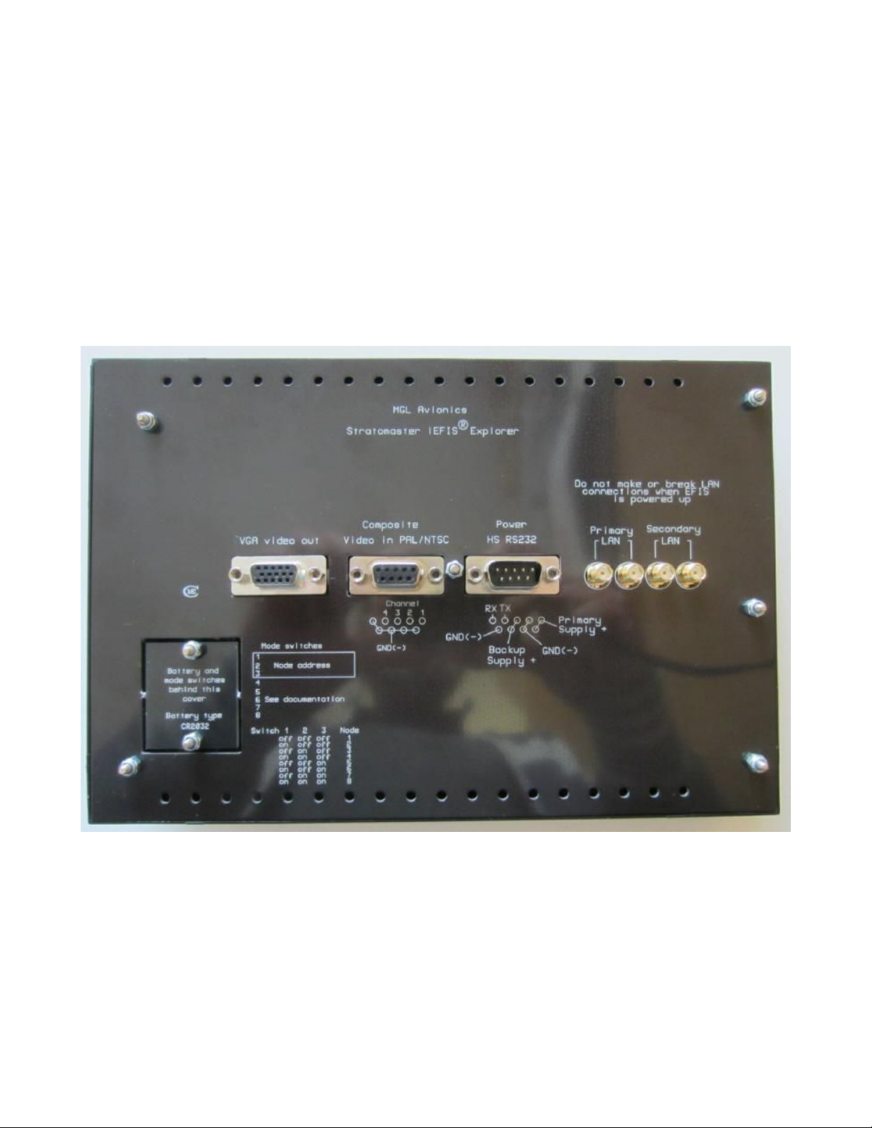
Example rear panel (Explorer EFIS)
This image shows the rear of a iEFIS panel.
Primary LAN: Two SMA connectors for the primary iBOX LAN
Secondary LAN: Two SMA connectors for the secondary iBOX LAN
Power: Male D9 socket for power, also provides a high speed RS232 port
Video: Female D9 socket provides four composite video inputs for cameras
VGA: Female D15 standard VGA socket provides video output. Note: Video timing may be
non-standard on some panels due to configuration. Please check if monitor can accept non
standard frame rates. Frame rates may vary depending on product from 30 to 60 Hz.
Access cover for internal lithium battery and DIPSWITCH array to set LAN node address.
Ensure that ventilation holes on top and bottom are not blocked in your installation. These
holes provide convection cooling for the internal electronics.
Page 6
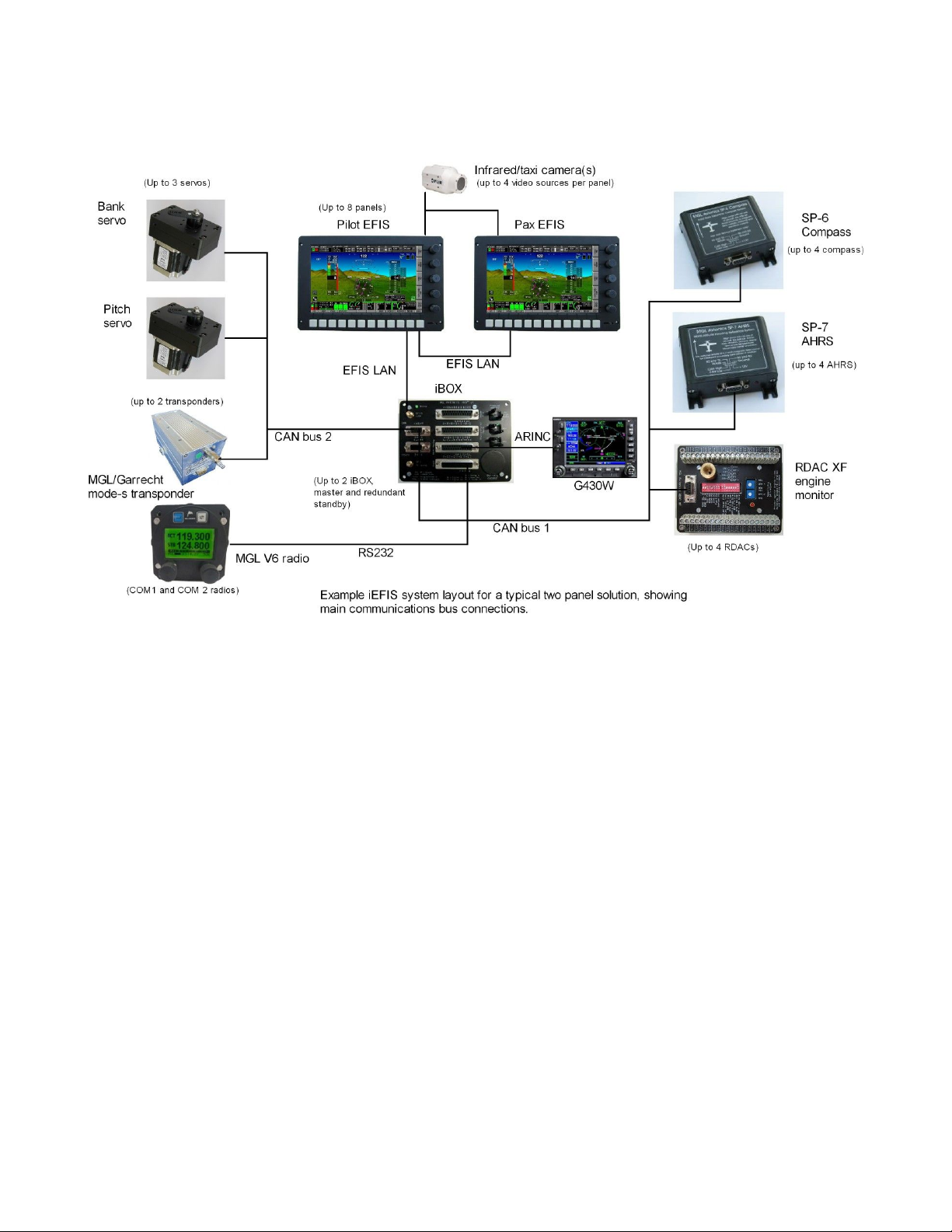
Example system design
The above image shows a typical small dual panel system with a single iBOX. It serves well
to illustrate the simplicity of the distributed system and ease of hardware installation.
Most MGL devices are connected to the iBOX using the CAN interface. The CAN bus uses a
simple two wire connection. A twisted pair wire is used for this. The CAN bus is simply
connected to each devices CAN interface terminals. The two wires are identified as “CAN H
and CAL L” and these connect to the corresponding terminals. Longer CAN bus runs require
a termination resistor on each end (120-180 ohms) while shorter runs (less than 9 ft) work
happily with just a single resistor of the same value.
Two CAN interfaces are available. These are exactly equivalent so you can connect any MGL
device to any of the two interfaces. The above image suggests to separate “sensors” and
“devices” onto the two CAN busses.
Note: Do NOT join CAN bus one to CAN bus two. They MUST remain independent.
Note: If you have two iBOX units, the CAN buses are joined between them: CAN bus
one to CAN bus one and CAN bus two to CAN bus two. The two iBOX units will use the
CAN bus to exchange data and status information.
The iBOX installation
Please consult the iBOX installation manual for specifics on the hardware installation of the
Page 7

iBOX system.
The iEFIS LAN
The transmission media for data between panels and iBOX is RG174 coaxial cable using
SMA connectors. Data is transmitted using a propriety, deterministic protocol at 2Mb/s.
Principles of the protocol are routed in the industrial ARCNET network topology with some
modifications. The protocol uses a token passing system in a TDM environment. The iEFIS
system lends itself to a communications master based protocol. The master is the iBOX as no
system makes sense without an iBOX.
A further utilization of the iEFIS network cable is the transfer of backup power during system
shutdown from the aircraft's battery via the iBOX “keep alive” wire. This greatly prolongs the
life time of panels built in user replaceable lithium backup battery. The backup battery is used
to maintain non-volatile memory in the panels.
Each panel supports two LAN connections, a primary and a secondary LAN. The secondary
LAN is only used if a second, redundant iBOX is used (this is optional).
Each LAN connection has two connectors. The two connectors are joined and provide a
simple means to extend the LAN cable to several panels. For example, in a two panel system
with a single iBOX, you would connect the iBOX LAN to the EFIS primary LAN on one panel
and then use the second primary LAN connector on the panel to connect to the primary lAN
panel of the second panel.
Image showing Primary LAN connected. Each group
of two connectors are simply connected internally to
each other. This implies that both connectors are
equivalent. These connectors eliminate the need to
create cable splices or use T-couplers.
Note: Never mix up the Primary and Secondary LAN. They must remain separate. Never join
the two LAN systems. They must remain independent.
IEFIS LAN terms
Primary LAN
The LAN connecting all of the primary LAN connectors at the back of the panels to the main
iBOX unit.
Page 8

Secondary LAN
The LAN connecting all of the secondary LAN connectors at the back of the panels to the
standby iBOX unit (this connection and the standby iBOX are optional).
Active panel
In the iEFIS system, one and only one panel is the “active” panel. The active panel has
special privileges such as being able to configure all of the system. The active panel also
controls the autopilot and is responsible for navigation and similar tasks.
Inactive panel(s)
All panels that are not “active” are “inactive”. They still behave like normal panels but cannot
configure the system. They do not actively navigate or control any connected devices. Should
an “inactive” panel require an action to be performed (for example, change of a radio
frequency), this request is sent to the “active” panel for execution.
“Inactive” panels can be seen as “passive” - they can do certain permitted functions via the
“active” panel and can monitor data as it flows on the LAN so essentially they behave in many
ways just like an active panel.
Assigning iEFIS panel addresses.
Before a system with more than one panel can be used, each panel must be assigned an
“address”. Addresses are simply numbers from 1 to 8 (for eight possible panels in a system).
You assign the address for a panel during installation. Remove the Back cover as shown in
this image and select the address on the DIPSWITCH array. A ballpoint pen works very well
to slide the switches.
Panel addresses assign a panels “priority”. The lower the number, the higher the priority. This
matters. The panel with the highest priority will be the “active” panel. Normally, you should
assign the highest priority to the panel in front of the pilot (I.e address “1”).
No two panels on the LAN may have the same address. This will cause a malfunction and
corresponding alerts will be shown on the affected panels.
Page 9
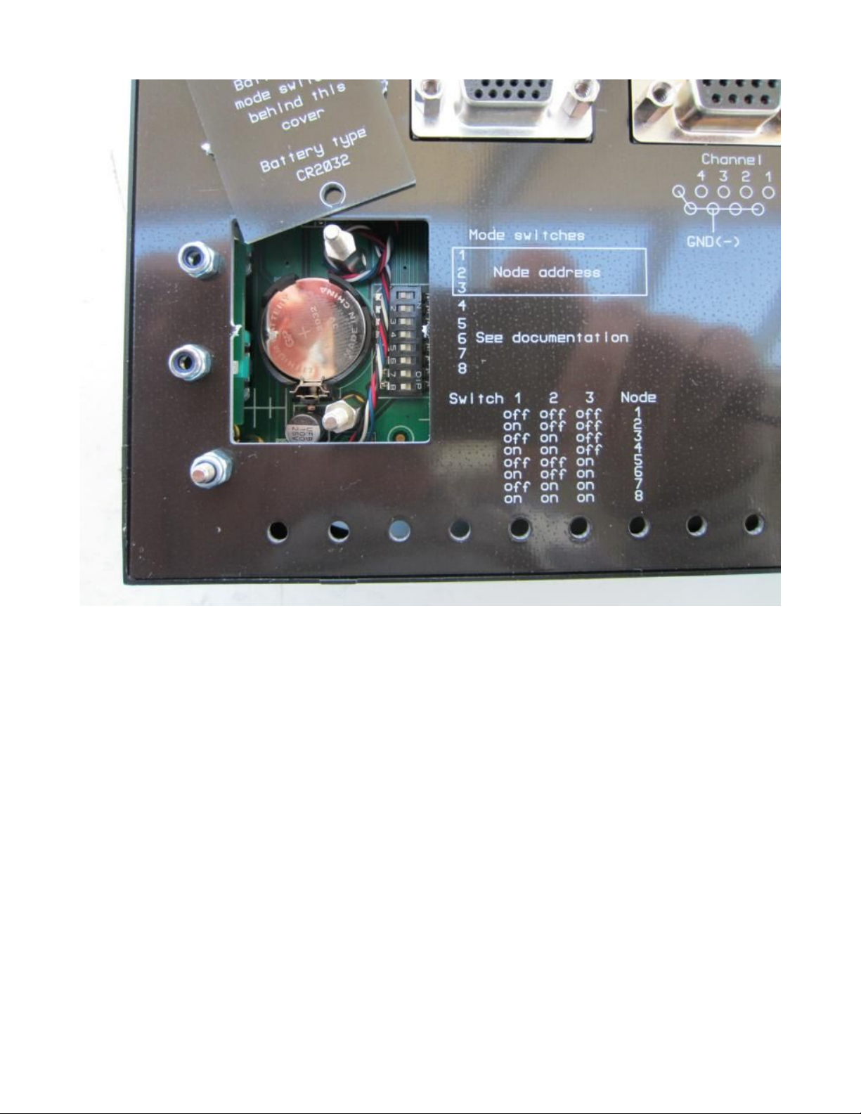
Node addresses are set using switches 1,2 and 3. The remaining switches are not currently
used but should be left in the “off” position to ensure compatibility with future software
functionality extensions that may use these switches.
Configuration of the iEFIS system
This section refers to the configuration of the software side of the system once the hardware
has been installed. Here you will select the various operating modes and settings and tell the
iEFIS system what is connected and where it is connected.
If you have more than one panel, your configurations will be done on the panel that is the
“active” panel. You can easily identify the active panel – it has the iBOX status field in the top
left corner of the display shown with a white surround.
Settings of your active panel are not automatically distributed to your other panels. You can
however “broadcast” your settings, once done, to the other panels. On each panel, you can
select what types of settings it should accept from the active panel. There may be cases
where you do not want the same settings on each panel so you are in complete control.
Page 10

Navigating the menus
This document follows this example convention:
Menu -> System Setup -> Engine monitoring setup -> Setup RDAC 1 probes and senders
This means:
1) Press the menu button
2) Tap on the “System setup” field or use the navigation buttons to select it.
3) Tap on the “Engine monitoring setip” field or use the navigation buttons.
4) Tap on the “Setup RDAC 1 probes and senders” field or use the navigation buttons.
Configuring a system for the first time
The first time you configure a system you will start by calibrating the tap screen.
You may do this at any time. The main reason you will calibrate the screen is the shape of
your finger. The system will measure the force you are pressing on the screen and will
determine the point you pressed the screen. Every finger is different and the center of force
will vary. Perform the calibration so you are happy the system detects the tap point where you
want it.
You may elect to have the tap point visible (I.e. Slightly above the point you press your finger)
or underneath your finger as you prefer. Experiment a little to find the best solution for you.
You can activate the touch screen calibration by clicking any of the top 3 rotary controls and
holding the control in the clicked position (press towards the panel) and then switch the panel
on (apply power) – hold until the system starts – it will now go straight into the tap screen
calibration function. This is also available in the setup menu.
To calibrate, follow the instructions in the center of the screen. Tap each of the three points in
turn – they are numbered 1,2 and 3. Then test the result by tapping on the screen and
observing where the hand pointer that appears points to. If you are in agreement, you can
confirm the new calibration or you can request a new attempt.
Once your tap screen calibration has been completed, it is time to choose one of the built in
options for the display layout. You may also use your own screen designs if you have
prepared them using the screen designer application. If you have obtained custom designed
screens from a third party, please refer to them for installation and configuration instructions
as they may differ from those presented here. In general however, most configuration should
be similar no matter what the screens look like.
You choose a general screen layout, engine display layout, fuel system layout and info screen
layout.
General layouts refer to the general appearance of the screen. You can choose from a
complex panel with pop down items on the top (such as radios) to a simple panel for a basic
system.
Engine layouts relate mainly to typical single engined systems and you will choose what items
Page 11

to monitor. For fuel tank layout your choice is how many fuel tanks and if you use fuel
pressure sensor and fuel flow sensor.
Custom screen designs are usually installed by executing a provided script file which includes
all screens and related items right down to individual setups. It is however also possible to
copy screen files individually to the systems “screens” folder. Any relevant screen file in this
folder automatically replaces any chosen “built-in” option.
Once your screen layout selection has been completed, it is time to configure the individual
settings. Here we start by setting the “real time clock” to the current time, setting up the
“hobbs”, “maintenance” and “tach” timers to their desired starting values, choosing the system
“units” (for example, you may want airspeed in miles per hour or knots) and attending to the
many individual settings that will dictate how the system will operate. These are outlined in
the following sections.
Page 12
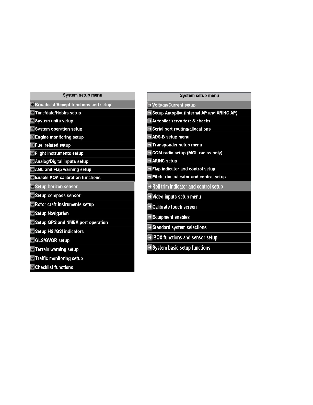
The “system setup” menu
Menu -> System setup
This is the central place in your iEFIS system where you control how the system operates.
This is the largest menu in the system.
Note: All setup functions are available in the “active” panel. All “inactive” panels may have
certain functions suppressed as they are not permitted to be executed in such a panel.
Broadcast/Accept functions and setup
Here you select if a panel may accept certain data from other panels. You can select to allow
setups to be accepted and what type of setups may be accepted.
You can also choose if a panel may accept navigation from other panels. Depending on your
requirements you may want to keep a panels navigation private to that panel. This will allow
you to setup a system where you can have two (or more) independent active navigation
solutions active at the same time.
This menu also contains a function allowing you “broadcast” your current setup. This provides
a quick way to send setups from your current panel to other panels. Example: Assume you
Page 13

have just changed the EGT temperature limits. You could now go and perform the same
changes on the other panels or you could simply broadcast your changes. Ensure that the
other panels have been setup to allow acceptance of such broadcasts.
Time/Date/Hobbs setup
Here you set your current system time, hobbs, tach, maintenance timer and airframe timer
values.
Note: all of these items are maintained in the iBOX so any changes are immediately available
to other connected panels.
If you have a dual iBOX system, ensure that both iBOX units are connected or else only one
iBOX will receive the updated values.
Note: You can use the iBOX status control to switch iBOX units at any time should you need
to confirm settings.
As a general rule, the standby iBOX will obtain all of these values from the main IBOX on
system startup if this is possible. For this reason both IBOX units must have at least one
functional CAN bus interface connected between them.
System units setup
Here you select the various units of measurement used in the system, for example
liters/gallons, mph/knots etc.
Note: By screen design some readouts may be fixed to a certain unit of measurement. This
does not apply to any of the built in screens, only custom designed screens.
System operation setup
Here you will find several fundamental setups like aircraft registration, automatic flight detect
settings etc. Please view and select all items in this menu as per your requirements:
Note: Aircraft registration entered here will be broadcast on “ADSB out” and mode-s
transponders.
Engine monitoring setup
This large setup item has a chapter of its own and is not described here.
Flight Instruments setup
Here you select basic flight instruments functionality such as V speeds for your airspeed
indicator, G-force meter ranges, VSI related functions etc.
Analog/Digital inputs setup
Here you can setup names for your iBOX analog and digital inputs. You can also setup
scaling for your inputs so input readings can be translated to meaningful readouts. You can
Page 14

also program alarm limits or states.
On-screen indications for these inputs require custom screen designs. Inputs can be
“connected” to bargraph and other analog displays or status displays for digital inputs.
Note: some inputs may be used for flap/trim position indicators – in those cases this is setup
in the relevant menus later in this section. The built in screens have displays for these that
you can enable.
AGL and Flap warning setup
This section allows you to configure a flap position indicator or select and configure a flap
controller (either VPX or MGL). You can also select a AGL warning limit that will result in a
voice alert “Ground proximity” if you have your iBOX audio output connected to your intercom
system.
Enable AOA calibration functions
Selecting this menu enables the AOA calibration flight items in the menu. These items depend
a little of the type of AOA system selected (Flight instruments setup).
Typically you calibrate lowest AOA (close to maximum speed straight and level flight), flaps
retracted stall and full flap stall. The latter two are referred to as “yellow” and “red” stall limits
as shown in the AOA indicator.
Note: The AOA indicator is a standard part of the built-in screen design. It is suppressed until
enabled.
Setup horizon sensor
Here you will find basic calibration functions for your AHRS. You can set bank/pitch angles to
zero and also slip to zero. This can be used to cancel out minor installation inaccuracy.
Please note: This should only be used to cancel out minor errors. If you detect larger angle
errors – please confirm that your AHRS sensor is correctly aligned with the airframe.
Setup Compass sensor
This section contains compass calibration functions. This is described in a separate document
common to all MGL EFIS systems.
Rotor craft instruments setup
This section contains mainly setup for the combined rotor craft engine and rotor RPM
instrument available with custom screen designs. Even if that is not used, basic rotor RPM
setups are found in this section.
Setup Navigation
Here you will find many setups directly related to navigation.
Page 15

If you have multiple navigation databases installed, you can select the currently active
database here. Also view the separate document “MGL Avionics map and database
installation”.
Setup GPS and NMEA port operation
Select GPS source used for position, heading and track if you have multiple sources. The
standard source is the iBOX (it has a built in GPS).
You can also select several optional NMEA sentences to be sent over the NMEA port. The
NMEA port is RS232 port 6 on the iBOX.
Setup HSI/GSI Indicators
Select which navigation sources you have connected in your system. Only navigation sources
you have enabled here can be selected using the HSI/GSI setup menus and functions.
GLS/GVOR setup
Here you setup details on how you would like the simulated ILS/Glideslope and simulated
VOR to work.
ILS/Glideslope is available as “GLS”. This uses the GPS in combination with runway
geographical data to emulate ILS and glide slope. Runway data is contained in your active
navidata file.
Please select the desired glide slope and runway intercept distance from the threshold.
Typical values may be 3 degrees and 300 feet for smaller aircraft.
VOR is simulated using the known geographic locations of VOR beacons in your navidata
database. DME is also simulated based on this data.
For VOR you can select a fixed maximum range of the simulated VOR beacon.
Terrain warning setup
Please select how you would like the GPS based terrain warning system to work. Terrain
warning requires that you install terrain data.
Traffic monitoring setup
Select details on the traffic monitoring system. For example, set up horizontal and vertical
distances before a traffic warning is activated.
Checklist functions
Here you can create and edit checklists. These are then available as you select the “check”
softkey. Checklists are text files you can also create using a suitable text editor (for example
note pad). Checklists may contain up to 32 lines (check items). Please use short descriptors
for every check item and verify that the lines will fit into the space provided.
Page 16

Tip: For sophisticated checklists consider creating a custom screen. Create checklists as
images and convert these as MIF files using the available MGL Avionics MIF converter. You
can then insert these checklist images as background to “info” pages (up to 10 pageable info
pages per screen). The checklists you create this way can then be mixed with any of the
available screen items.
Voltage/Current setup
Voltage monitoring and current measurement calibration functions.
Currents are calibrated by setting the “zero” point – this is the value measured at the current
monitoring port when no current is flowing through the current monitoring device. In addition a
“gain” value is entered so correct current is shown for the voltage deviation caused by the
current at the current measurement port.
Setup Autopilot
Please refer to the autopilot document for details on the autopilot setup.
Differences to the document:
iEFIS supports only MGL Avionics servos on CAN bus. For this reason selection of other
servo types is not available.
Autopilot servo tests and checks
This functions is used to engage and position servos for purposes of installation and
maintenance. It is not available if the aircraft is in “flight mode” or airspeed is not zero.
Serial port routing and allocations
Select what you have connected to the various serial RS232 ports available.
Note: Port 1 and Port 2 are high speed ports favored for devices like the VPX ECB and
Navworx ADSB system. If these systems are not used, these ports may be used for any other
device.
Port 6 is reserved and used as NMEA port so it is not available for general use.
After you have selected ports, please restart the system so changes are applied system wide.
ADSB setup menu
Select which kind of ADSB system you have connected. You can use passive (receiver only)
as well as transceivers (ADSB-OUT). In case of ADSB out, you need to enter various kinds of
fixed information that will be transmitted by your ADSB system.
Please do not activate your ADSB transceiver until you have entered all of the data correctly.
Failing to do so will result in your unit transmitting incorrect data. ATC is not going to like that !
Recommendation: Consider activating the ADSB/Transponder slave function if you are also
using a remote controlled transponder (mode-c or mode-s). If slaved, you can enter squawk
Page 17
Loading...