

Page 1
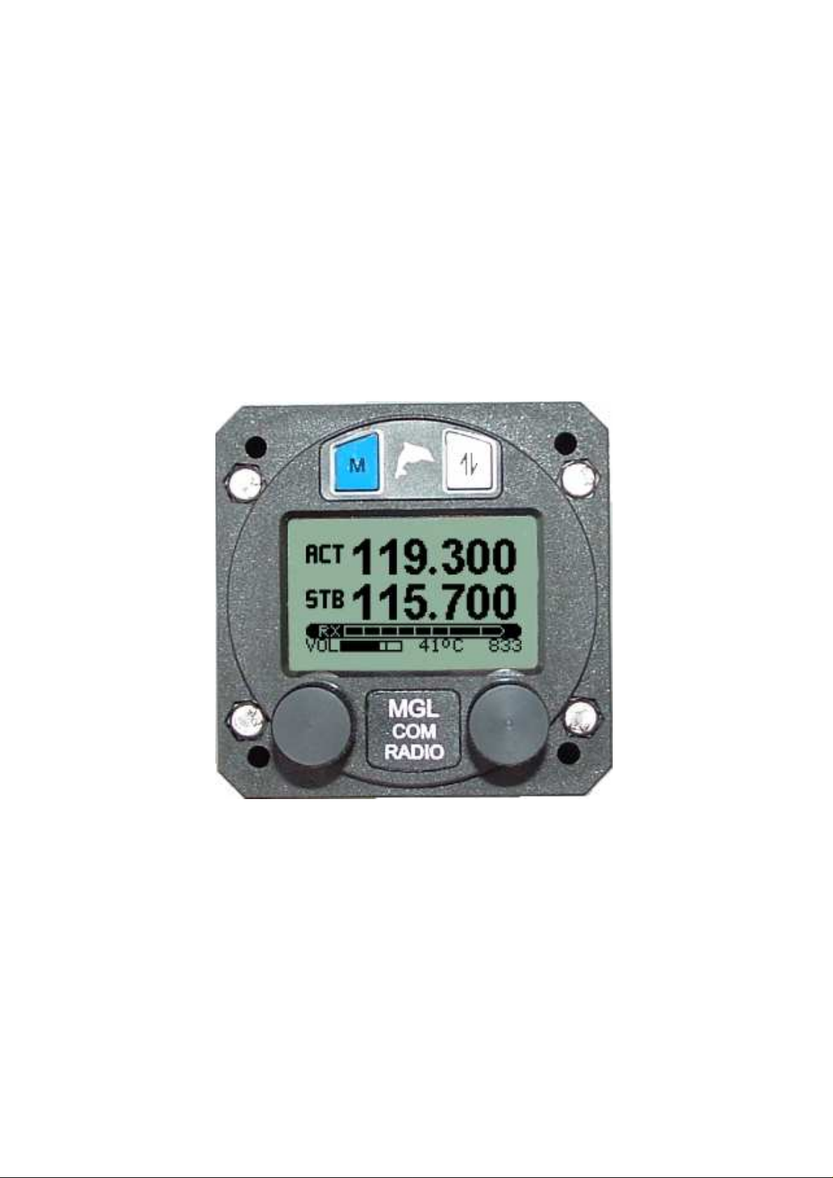
MGL Avionics
VHF Airband Transceiver
Model V6
User & Installation Manual
VERSION 1.1 - 10/2011
Page 2

General
Please read this manual before operating the V6 Transceiver
Please include this manual if ownership of the V6 Transceiver changes
Operational limitations, conditions and restrictions
Do not operate this unit outside of its specified temperature range – this may
result in malfunction or damage to the unit.
Observe the installation wiring diagrams. Incorrect wiring may damage this
unit.
Never operate this unit outside of its specified voltage range. Doing so may
cause serious damage to this unit. At all times ensure that no reverse polarity
power is applied to this unit. Reverse polarity will destroy this unit.
This Transceiver is designed to withstand the possible power surges that may
occur in a correctly wired power supply system of a typical aircraft. For this
reason the Transceiver may be left switched on when engines are started.
Please note that the supply voltage may drop below minimum operating
voltage during engine cranking. During this time operation of the radio will not
be possible.
Do not operate the transmitter of this unit without connecting a correctly
adjusted antenna. Doing so may result in damage to the unit.
The V6 Transceiver is not FAA type certified. This unit may only be used in
aircraft where such a unit is permitted under local rules. Typically these rules
permit operation in non-type certified aircraft such as home built and
experimental or sport category aircraft. Limitations may exist on maximum
altitudes above which a non-certified airband Transceiver may not be
operated. Please check local rules with the relevant authorities.
Use of this radio may be subject to a radio station license. Please contact the
local radio frequency spectrum governing body (such as the FCC) to inquire
as to the procedures required to obtain a radio station license.
Operation of this Transceiver may only be allowed by persons holding a valid
radio license (restricted or full).
Please do not operate this Transceiver illegally.
Please do not operate this Transceiver in an environment or in conditions
where its transmissions may cause interference to other electronic equipment
or systems.
Never operate an airband radio without the required qualifications to do so.
Never cause a nuisance to aircraft on the ground or in the air by misuse of
this Transceiver in any way.
Never compromise the safety of other aircraft with lengthy transmissions.
Keep transmissions short and to the point following established air to air and
air to ground rules and procedures.
2
Page 3

Table of Contents
General............................................................................................................2
Operational limitations, conditions and restrictions......................................2
The V6 Panel...................................................................................................5
The V6 controls................................................................................................6
The 'VOL/TEST' knob..................................................................................6
The 'ACTIVE' button....................................................................................7
The 'FREQUENCY' knob.............................................................................7
Setting frequencies..................................................................................8
Changing channels..................................................................................8
The STATUS display....................................................................................9
RX/TX bargraph......................................................................................9
Annunciators.........................................................................................10
The 'MENU' button.....................................................................................11
Menu structure.......................................................................................11
First Level Menu........................................................................................13
Ambient noise suppression...................................................................13
Squelch adjustment...............................................................................13
Program channels.................................................................................14
Contrast.................................................................................................14
Microphone level...................................................................................15
Music level.............................................................................................16
Auxiliary input levels..............................................................................16
Microphone bandpass filter...................................................................16
Scanning state at power up...................................................................17
Frequency lists......................................................................................17
Setup ....................................................................................................17
Second Level Menu...................................................................................18
TX MIC VOX / HOT...............................................................................18
TX LOCK ON / OFF...............................................................................18
P-scan ON / OFF...................................................................................19
PTT Configuration.................................................................................19
Flip-Flop FS / Direct FS.........................................................................19
MIC Levels............................................................................................19
Pilot Isolate configuration......................................................................19
Auxiliary input configuration...................................................................20
Audio output configuration.....................................................................20
Sidetone configuration...........................................................................20
CHANNEL spacing................................................................................20
RESET..................................................................................................20
Installation......................................................................................................21
General installation notes..........................................................................21
Planning.....................................................................................................22
DB-25 connector pin out............................................................................23
Typical wiring diagrams.............................................................................24
Transceiver installation..............................................................................25
Specifications – Subject to change without notification.................................26
Physical.................................................................................................26
Transmitter............................................................................................26
Receiver................................................................................................26
Other.....................................................................................................27
Page 4

Power....................................................................................................27
FCC Statement..............................................................................................27
REFERENCE.................................................................................................28
4
Page 5
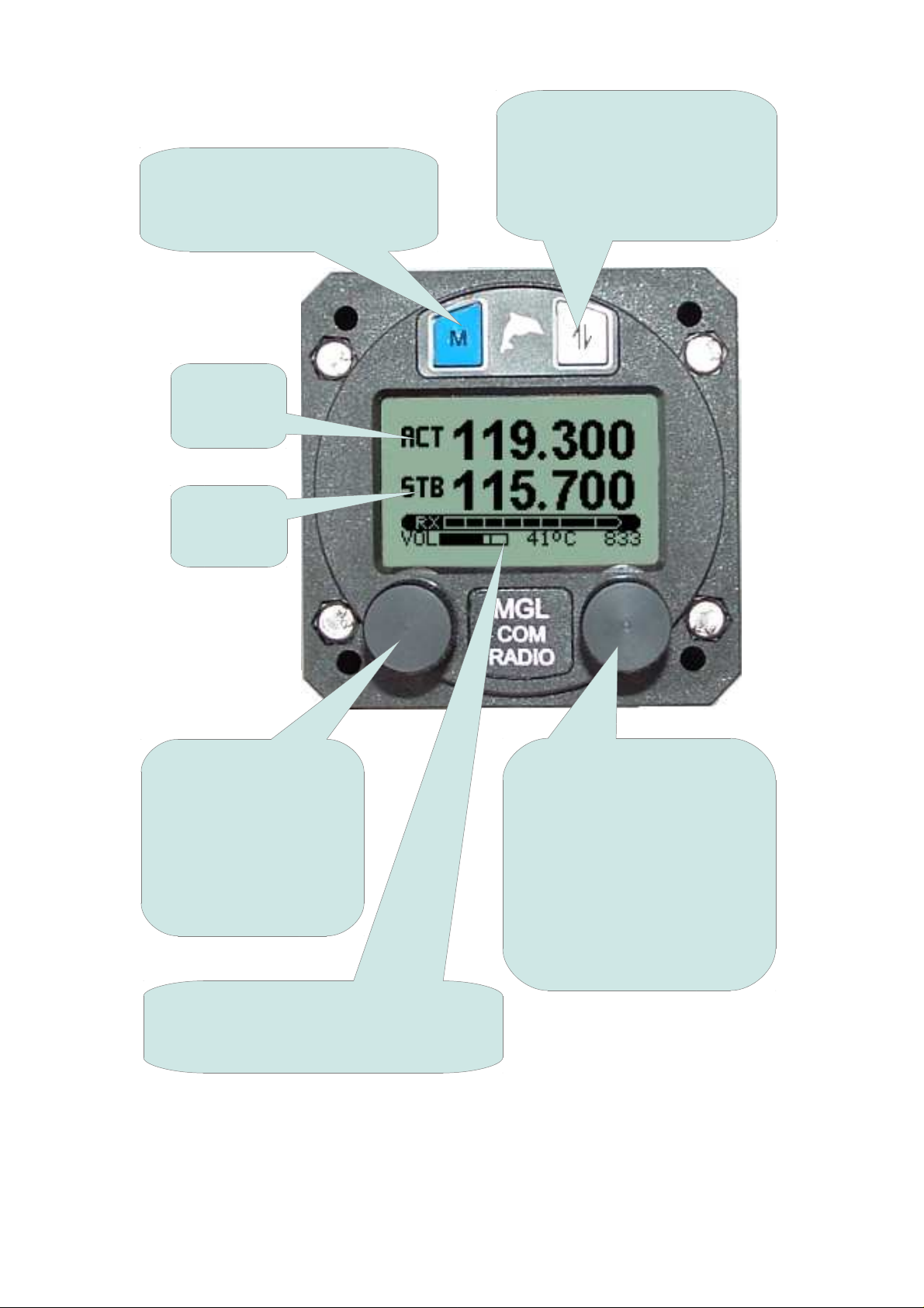
The V6 Panel
MENU button. Press this button
to enter the menus. There are
many adjustments and setup
options
The current
active
frequency
The current
standby
frequency
ACTIVE button. Pressing this
button exchanges active and
standby frequencies.
NB: holding this button down
enables further functions
VOL/TEST knob. This
provides adjustment of
VOLUME. Pressing the
knob inwards selects
TEST and 'opens' the
squelch. Holding this
knob down enables
further functions
STATUS display showing volume level,
voltage or transmitter temperature and
frequency setting information
This shows the V6 Transceiver in a Factory Default configuration with 'FlipFlop' frequency selection. The V6 Transceiver can be operated in other
modes depending on setup and installation.
5
FREQUENCY knob. This
provides adjustment of
operating FREQUENCY or
CHANNEL. In MHZ/KHZ
mode pressing this knob
inwards selects between MHZ
and KHZ entry. Holding this
knob down for 2 seconds
changes between MHZ/KHZ
and CHannel entry.
Page 6
The V6 controls
The 'VOL/TEST' knob
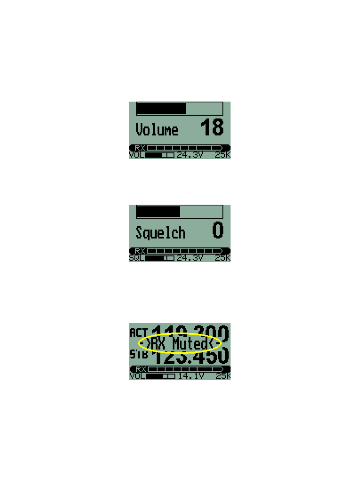
Rotating this control knob will adjust headphone volume. The Transceiver
defaults to volume adjustment. While adjusting the volume, the display will
change to a large bargraph and number indicating volume level setting.
Pressing the knob inwards will disable the squelch on the Receiver and allow
a quick receiver TEST. Squelch setting may be changed in the First Level
Menu.
Holding the VOL/TEST knob down and rotating counter-clockwise reduces
the volume level of the Radio only. This allows easy conversation over the
Intercom in the presence of heavy radio traffic. The reduced volume level is
adjustable downwards, but may not be switched off. While the Radio is
'MUTED' the screen flashes every five seconds.
Radio volume is restored by holding the VOL/TEST knob down and rotating
clockwise. Also, volume is automatically returned to normal by using the
transmitter (pressing a PTT).
6
Page 7
The 'ACTIVE' button
With a Factory Default setup, the display shows two frequencies – active and
standby. When the ACTIVE button is pressed, the standby frequency
becomes the active frequency and the active frequency becomes the standby
frequency.
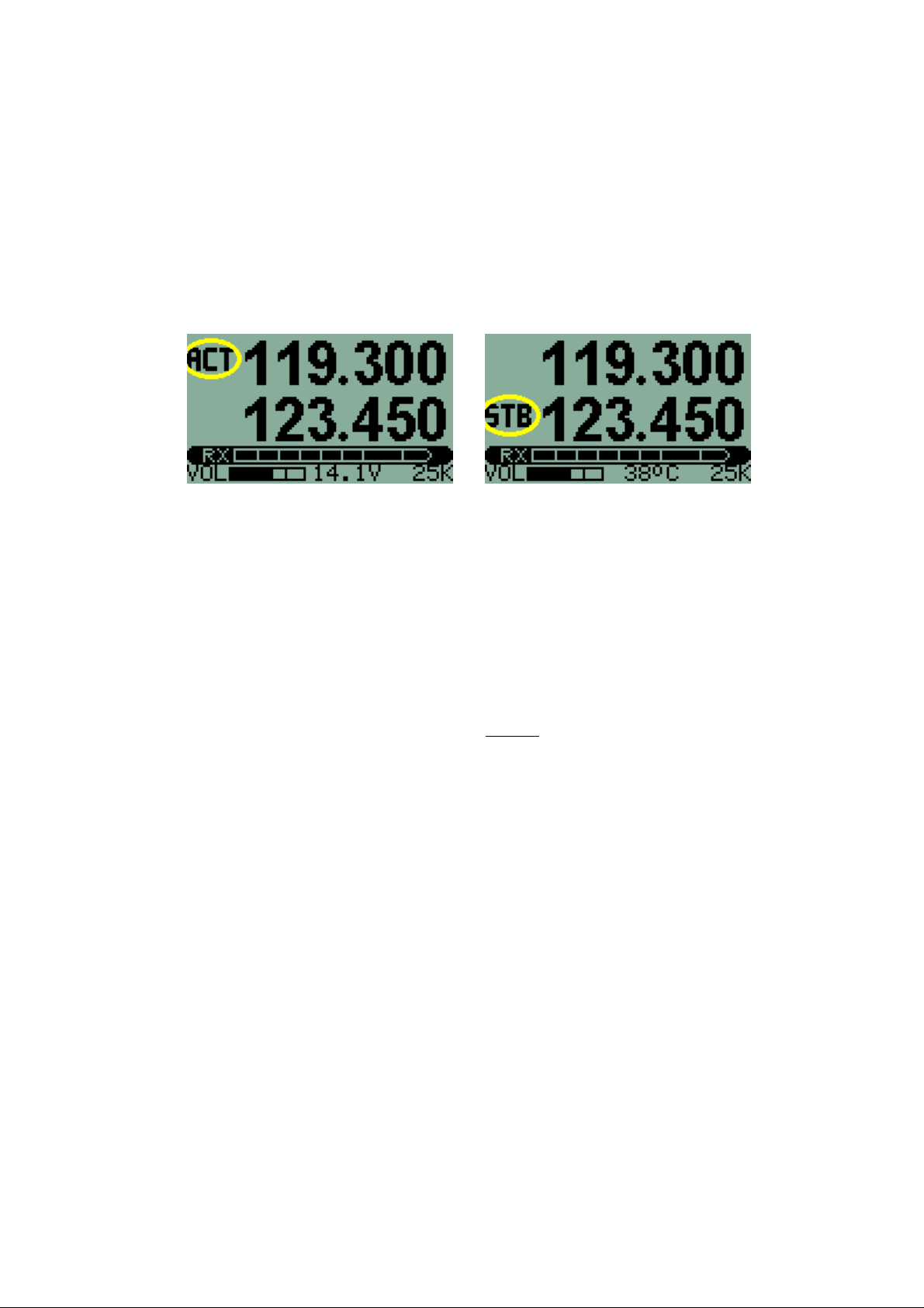
Holding down the ACTIVE button for 1 second will enable or disable
scanning (the Receiver 'scans' rapidly between active and standby
frequencies to check for incoming transmissions). Scanning is indicated by
alternate flashing of the ACTIVE and STANDBY annunciators on the display.
A short burst of beeps in the headphones gives an audible indication as
scanning is enabled or disabled so that it is not necessary to look at the
display. Three beeps indicate scanning has been enabled and two beeps that
it has been disabled.
If a transmission is detected, scanning stops and it is possible to listen to the
received signal. Scanning continues when the transmission ends. The
transmission may be on either the active or standby frequency.
NB: Holding down this button for three seconds will
automatically set the active frequency to the emergency
channel on 121.500 MHz.
It is possible for the Transceiver to operate with direct frequency entry. This
configuration may be selected in the second level of the Menu system. Only a
single frequency is shown on the display - the active frequency. This
frequency is changed directly. There is no standby frequency and no
scanning is possible.
The 'FREQUENCY' knob
This control is used to set the operating frequency of the Transceiver. The
setting acts on the standby frequency (or the active frequency if direct
frequency entry is being used).
A frequency is set on the V6 Transceiver either by entering MHZ/KHZ or by
selecting a memory Channel. Holding the FREQUENCY knob down for two
seconds changes from one to the other.
7
Page 8
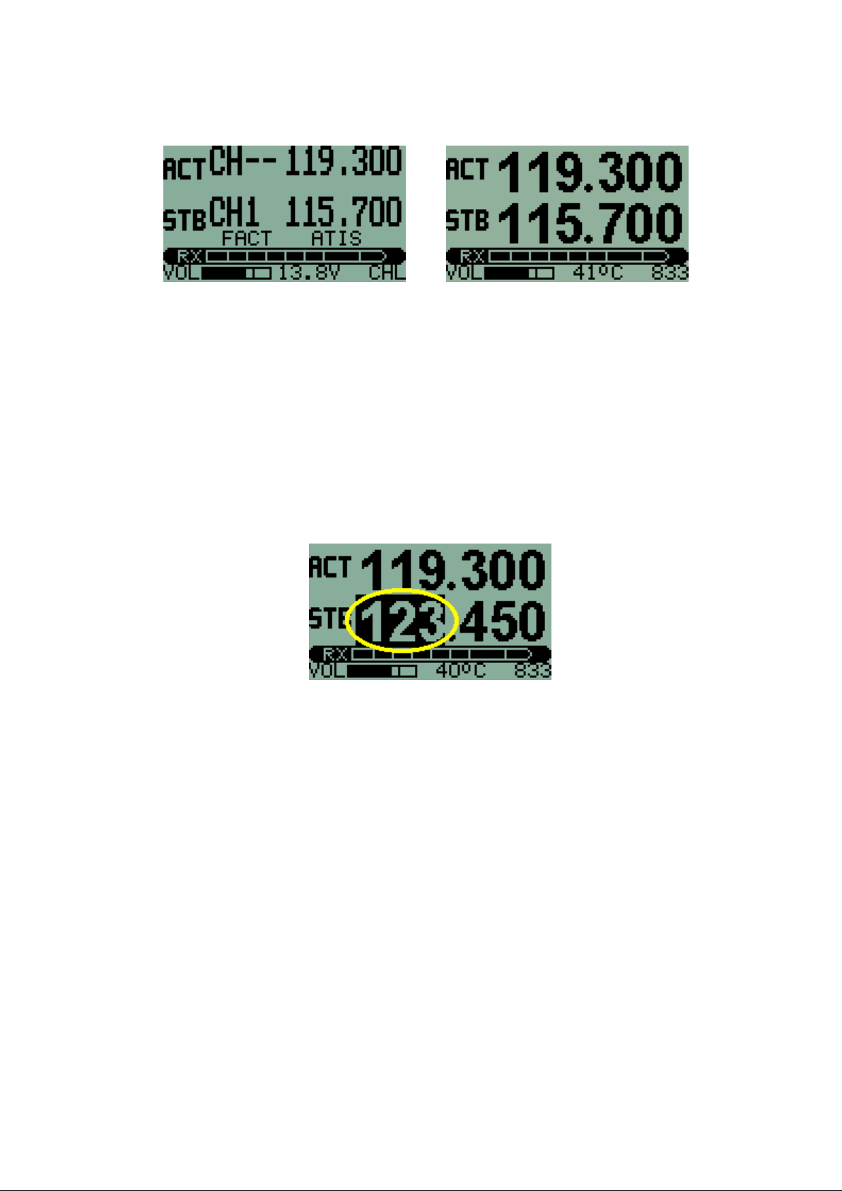
An indication of whether the Transceiver operating frequency is to be set by
MHZ/KHZ or CHanneL selection is shown on the display as indicated.
The spacing between frequencies may be in steps of 25KHz or 8.33KHz.
This may be set in the Second Level Menu. A 'speed-up' function is provided
for the FREQUENCY knob so that a new frequency or channel may be set up
quickly and easily.
Setting frequencies
With the method of frequency entry set to MHZ/KHZ a frequency is set by
pressing the FREQUENCY knob inwards momentarily until the desired part of
the frequency entry is highlighted on the display. The graphic below shows
'MHZ' entry, with that part of the display highlighted (with a dark background).
While the desired part of the entry is highlighted, the setting may be changed
by rotating the knob.
NB: KHZ rolls over without changing the MHZ value. Thus for example,
increasing KHZ will change from a frequency display of 124.975 to 124.000.
Likewise, decreasing KHZ from 124.000 will change the setting to 124.975.
This makes KHZ selection easier.
Pressing the FREQUENCY knob briefly switches between MHZ and KHZ
entry.
Changing channels
To switch to memory CHanneL entry hold down the FREQUENCY knob for
two seconds. Memory Channels may then be selected by rotating the knob.
NB: Channel selection rolls over from 99 to 1 or from 1 to 99.
8
Page 9
NB: If a frequency list has been uploaded from a compatible EFIS or GPS
and activated by menu function (in the First Level Menu), only 20 channels
will be available. The list size is determined by the SL30 and SL40
communications protocol and may have from 1 up to a maximum of 20
entries.
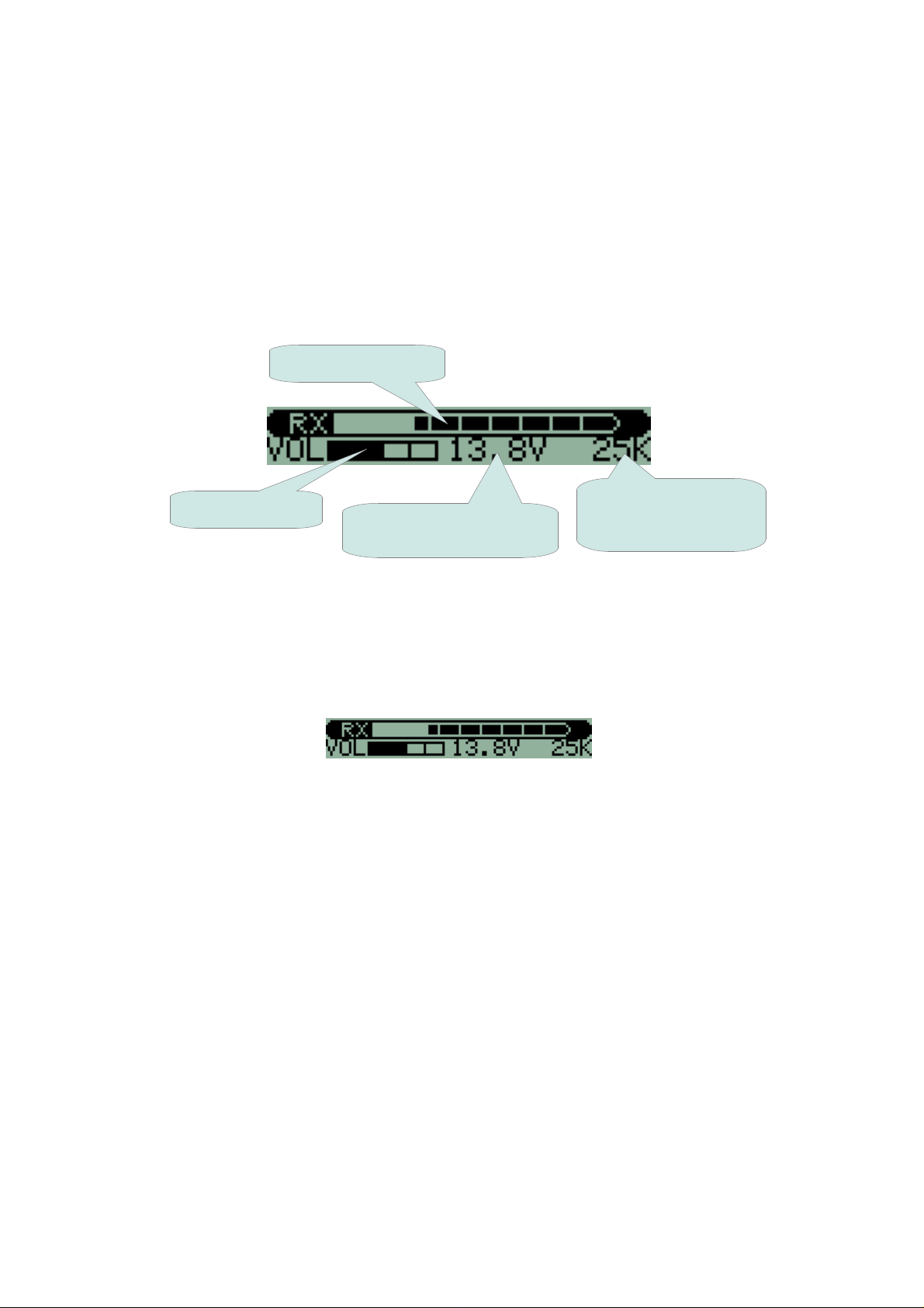
The STATUS display
The STATUS display provides an Rx/Tx bargraph, and annunciators for
volume level, supply voltage or transmitter temperature and frequency
spacing.
Rx/Tx bargraph
Frequency spacing
Volume level
Supply voltage (or
transmitter temperature)
25KHz/8.33KHz or
CHANNEL memory
RX/TX bargraph
The V6 Transceiver display includes a bargraph showing the strength of a
received signal during RX or modulation level of the transmitter during TX.
Due to good receiver sensitivity, signals of medium strength will fill the
bargraph.
Receiving transmission of moderate strength
During TX the bargraph shows modulation of the actual transmit carrier. This
is a visual form of side tone making it possible to judge how well the signal
from the microphone is modulating the transmitter. Note that this bargraph
does not show the level from the microphone – this shows directly the
modulation of the signal being transmitted.
Good modulation will cause the bargraph to just touch the right hand side of
the display for the loudest parts of transmission. Often this is achieved with
click “T” or “SHH” sounds. Average level of speech during transmission
should be between 50% and 75% on the bargraph.
The modulator for V6 transmitter is under direct microprocessor control. The
audio signal to be transmitted is processed using digital signal processing
algorithms before being sent to the modulator.
Software control of the modulator allows precise control of modulation under
varying power supply and temperature conditions. It also allows wide range
control of the audio signal amplitude at the modulator. This prevents overmodulation while still allowing deep and rich modulation of the carrier. This
9
Page 10

results in excellent audio quality of the transmitted signal and extends the
effective range of the transmitter.
Correct microphone level adjustment is required for optimum modulation
level. If a headset is changed to another type, microphone level should be
checked before use. The microphone level adjustment function (in the First
Level Menu) has a convenient bargraph readout, making adjustment simple
and accurate.
Annunciators
The bottom line of the display provides three annunciators.
On the left-hand side, a small bargraph indicates the setting of the volume
control.
In the center is a display of nominal supply voltage at the power terminals of
the connector on the rear of the case. This periodically changes to indicate
the temperature of the transmitter. The temperature is in Centigrade and may
rise as high as 95°C for high ambient temperatures and during periods of
intense use of the transmitter. Output power is reduced automatically at high
temperatures to limit the possibility of damage to the transmitter.
On the right-hand side is an indicator of the frequency method or spacing
used for setting the operating frequency. When using Channel memories, this
shows 'CHL'. For entering frequencies, either in Flip-flop or Direct modes, this
shows the frequency spacing. '25K' indicates that the frequency may be set in
steps of 25KHz while 833 indicates that frequencies are available in steps of
8.33KHz. Frequency setting and readout on the display is according to ICAO
standards for both spacings.
www.MGLAvionics.co.za to download the latest version of this User and
Visit
Installation Manual.
10
Page 11

The 'MENU' button
The MENU button allows entry to the two level menu system at any time. The
menus provide access to options and adjustments such as setting intercom,
VOX, and audio levels, and many others.
Menu structure
The V6 Transceiver provides setup options and adjustments on two menu
levels. The First Level Menu is accessed by pressing the “MENU” button. The
Second Level Menu with options that are usually only used during installation,
is accessed via the “Setup” function in the First Level Menu.
VOX/VOGAD adjustments
Squelch adjustment
Edit memory channels
Display contrast adjustment
Microphone level(s) (All or four separate levels according to
configuration)
Music level and mute adjustments
FIRST LEVEL MENU
Auxiliary input level(s) – according to configuration
Microphone bandpass filter
Scanning state at power up
Select from channel list(s) (ONLY available if lists are loaded)
Setup - enter Second Level Menu
TX microphone - HOT or VOX/VOGAD
TX lock on RX active
Priority scanning of active frequency
PTT configuration – Join or Separate
Flip-Flop or Direct frequency entry
Microphone level configuration – 1 or 4
Pilot Isolate configuration – 1+3 or 2+2
Auxiliary input configuration
Audio output configuration
SECOND LEVEL MENU
Sidetone configuration
25KHz or 8.33KHz channel spacing
RESET to factory defaults
11
Page 12
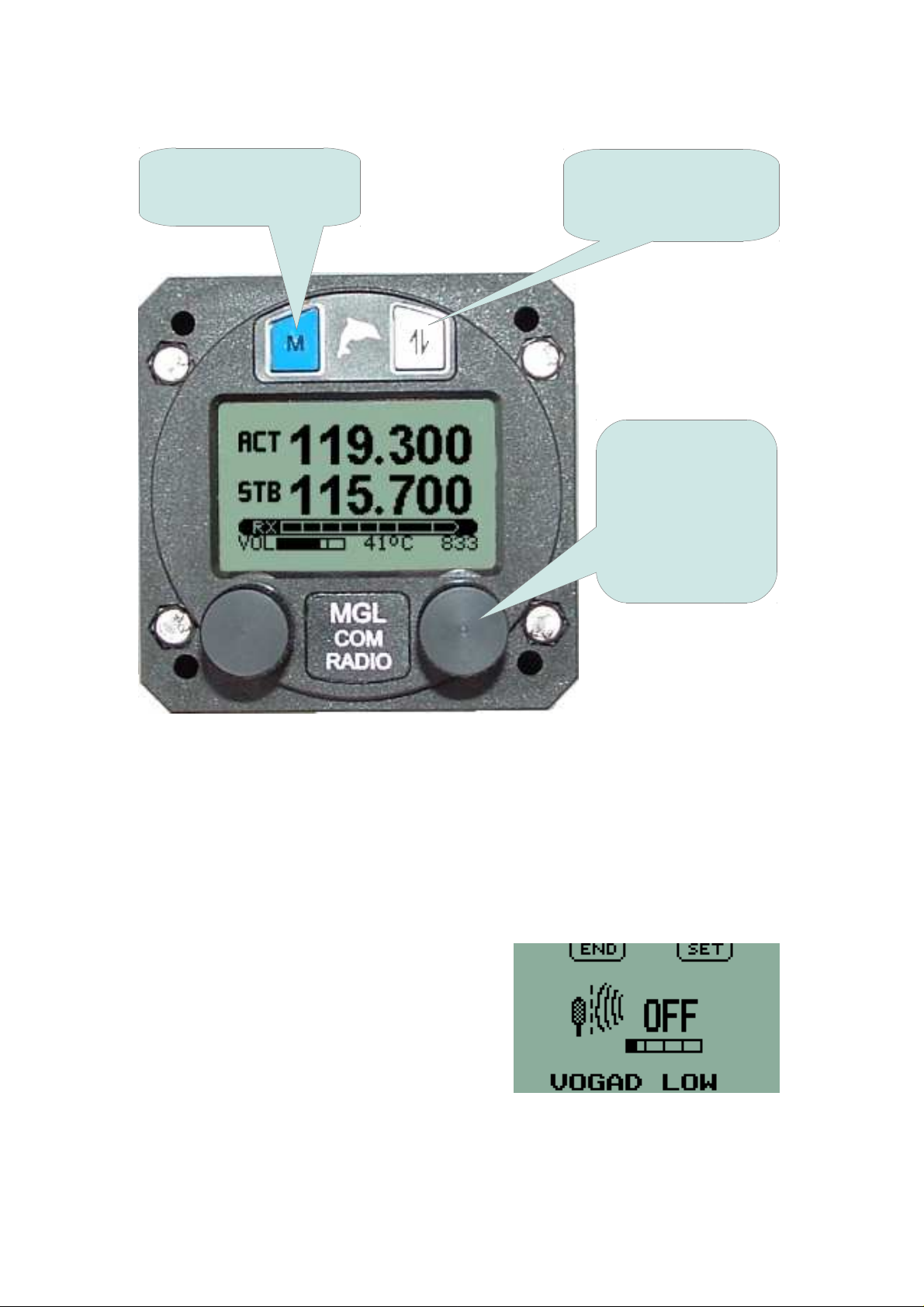
To return to normal
operating mode press
the MENU button
Press this button to
change/edit/select the
current menu item
Rotate the knob to
select the desired
menu function.
Press the knob to
change/edit/select
the current menu
item
Once a menu function has been selected, the display will change according
to available functionality. Pressing of the ACTIVE button and the
FREQUENCY knob are interchangeable except where indicated. Pressing
the MENU key as required will return the unit to the normal operating screen
– either Frequency display or Channel display. Also, any menu function will
default to the normal operating screen after 60 seconds.
As an example, this is the display for the
ambient noise suppression system function
allowing selection of the type of system to
be used and adjustment of the
level/'strength' of the selected system.
12
Page 13
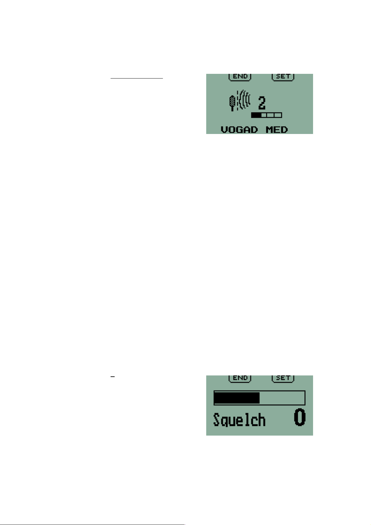
First Level Menu
Ambient noise suppression
Factory Default: VOGAD MED 2
The V6 Transceiver provides four different
ambient noise suppression systems.
Pressing the FREQUENCY knob (or the
ACTIVE button) cycles through the four
types. Rotating the knob adjusts the level or
'strength' for the selected type.
●
VOGAD (three types)
This is a proprietary VOGAD system developed by MGL Avionics. It
uses gain shaping with digital processing of the audio signal from the
microphone. The voice signal envelope is detected and used to
modulate microphone gain. Three types are provided – LOW,
MED(ium) and HIGH. The type should be selected depending on noise
level in the aircraft. Most general aviation aircraft will use a medium
setting. Each VOGAD type has up to 8 levels. As the level is
increased, gain falls more sharply below a threshold as set by the
VOGAD type.
It is important not to set the microphone level too high. This must be
correctly matched to the selected type. If the microphone level is too
high ambient noise may exceed the threshold for that type.
With the VOGAD system set up correctly, the microphone will seem to
be highly directional so that it must be placed directly in front of the
mouth.
A suggested starting point is VOGAD MED(ium) level 2.
●
VOX
This type simply switches off the microphone if sound is below a preset
threshold. Switching is done in a digitally controlled “soft” manner so
no sharp clicks are audible. Adjust the level so that ambient noise is
just below that required to switch on the microphone. If the level is set
too high, part of the first syllable may be 'lost'.
Squelch adjustment
Factory Default: 0
The display provides a large bargraph and
number for reference when setting the
squelch level. Pressing the FREQUENCY
knob (or the ACTIVE button) activates the
Squelch adjustment function. This is
indicated by the reference number flashing.
Rotating the FREQUENCY knob adjusts the
level between limits of -16 and +15. Adjust the squelch level so that static
noise from the receiver is just 'squelched' out. Too high a level may result in
weak transmissions not being received. Too low a level may result in noise
breaking though. A setting is accepted by pressing the FREQUENCY knob.
13
Page 14
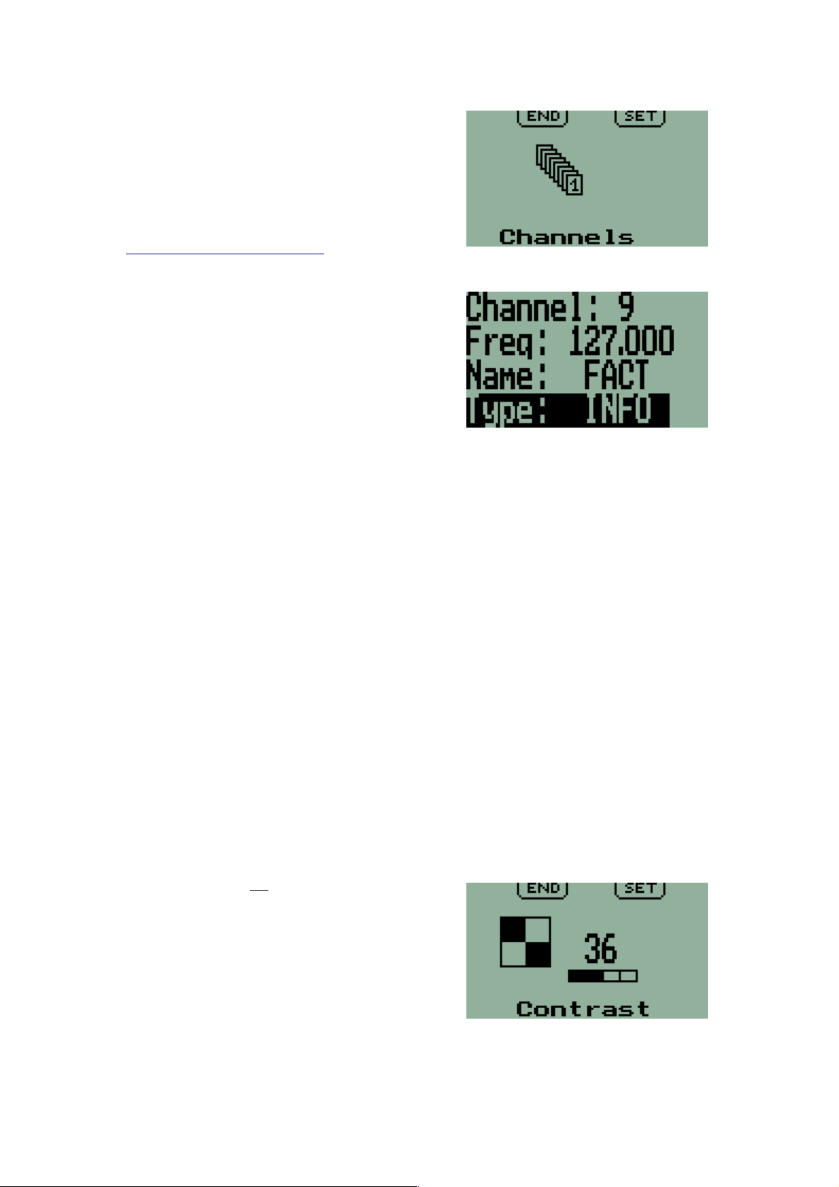
Program channels
This function supports memory channel
programming.
Memory channels may be programmed
using this function or they may be
downloaded from a PC via an RS232
connection using software available from
www.MGLAvionics.co.za
The V6 provides 99 memory channels for
user programmed frequencies. Each
channel has an associated frequency,
'Name' for the frequency (for example
airport name or code), and 'Type' for the
frequency (for example “ATIS”).
Rotating the VOL/TEST knob moves the
highlight (the line with a dark background) to
select a line for editing.
Channel selected:
Rotate the FREQUENCY knob to select the number of the channel to be
edited.
Frequency selected:
Press the FREQUENCY knob to select between the MHZ or KHZ part of the
frequency setting (the MHz or KHz part will flash to indicate which is
selected).
Rotate the FREQUENCY knob to change the setting.
Name or Type selected:
Press the FREQUENCY knob to cycle through the character positions to edit.
A flashing 'underline' or character indicates the position to be edited. Rotate
the FREQUENCY knob to change the character. Up to six characters are
available.
When finished with editing channels, press the 'MENU' button to return to the
First Level Menu.
Contrast
Factory Default: 40
This function is for adjusting display contrast
as required. A value between 30 and 40 is
suitable for most environments. A lower
value results in a lighter display while a
higher value results in a darker display.
Adjust the contrast so that dark areas are
fully saturated while light areas do not show
any darkening.
14
Page 15
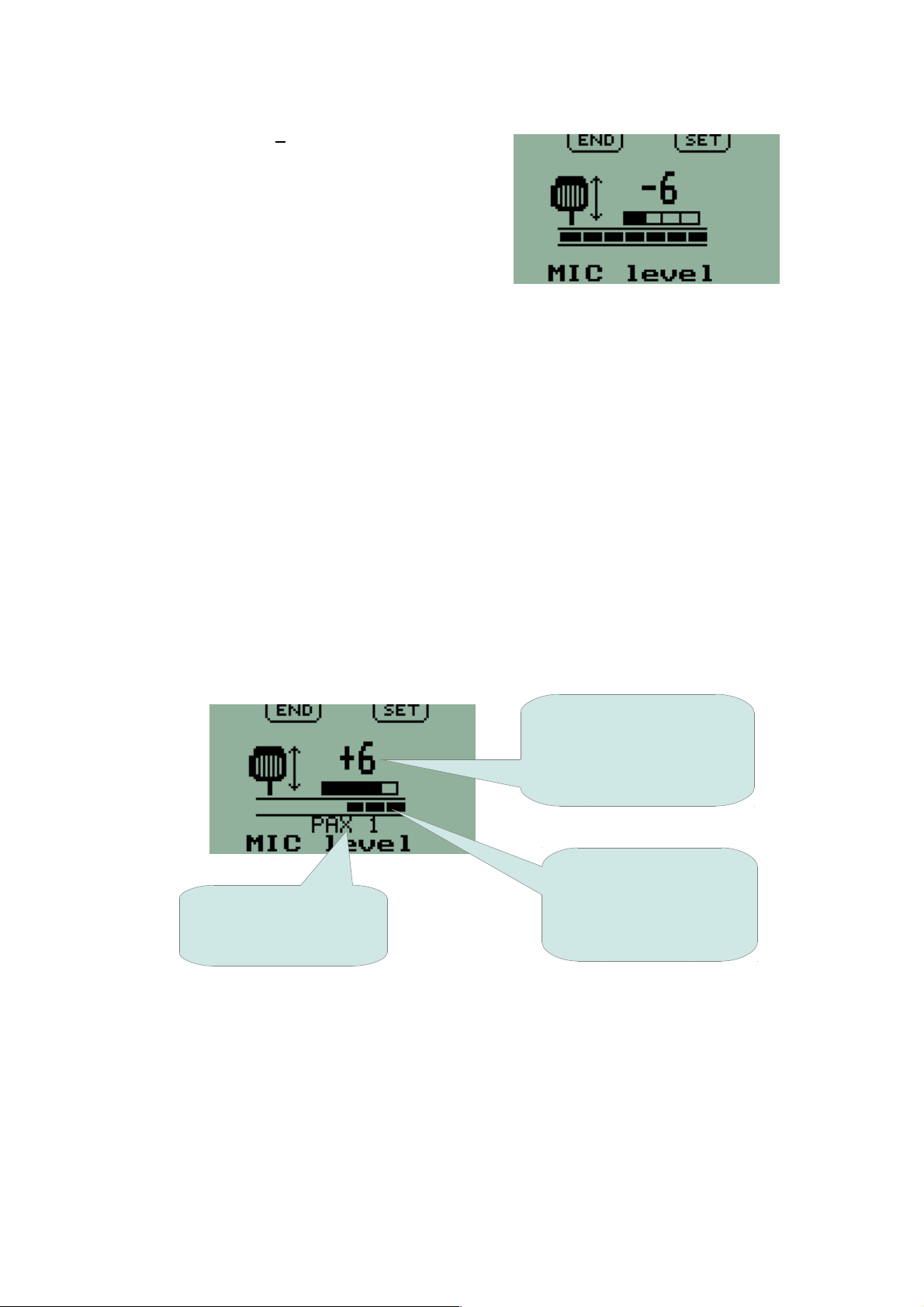
Microphone level
Factory Default: 0
This function allows adjustment of
microphone level. A bargraph is provided to
assist in adjustment to the correct level. The
level is correct when the bargraph remains
between about ½ and ¾ of the full range
while speaking normally into the
microphone, with excursions all the way to
the right only during the loudest parts of speech.
NB: For a single microphone, the level shown by the bargraph is for the Pilot
microphone input ONLY. No level is shown for the passenger microphone.
The adjustment affects all microphones equally.
Correct adjustment of this level is important. It affects operation of the
ambient noise suppression system and the modulation level of the
transmitter.
NB: By design the transmitter cannot be over-modulated if levels are set too
high. However, sound quality of the transmitted signal may suffer.
Using independent level settings for pilot and passenger microphone
circuits:
A function is available in the Second Level Menu to enable independent
adjustments for all four microphone circuits.
If enabled, each microphone has a separate screen for level adjustment.
Reference number
indicates selected level.
Flashes when selection
can be adjusted
Bargraph - indicating
Annunciator showing
microphone selected
for adjustment
correct MIC level
between ½ and ¾
during normal speech
15
Page 16
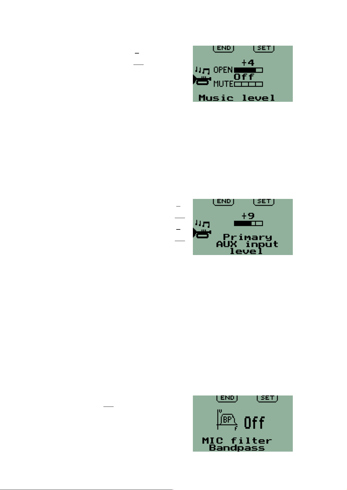
Music level
Factory Default: Open: 0
Mute: Off
A stereo music source such as an MP3
player may be connected to the stereo
music input.
Two adjustable levels are provided for this
input.
Open: This level applies if there is no audio from the intercom, the radio or
the auxiliary inputs.
Mute: This level applies if there is audio from any other source.
In particular, with the Mute level set lower than the Open level the music input
is reduced to the lower level when there is audio from any of the intercom,
radio or auxiliary inputs and returns to the higher level when that input
ceases.
Auxiliary input levels
Factory Default: Primary Open: 0
Mute: Off
Secondary Open: 0
Mute: Off
Two Auxiliary inputs are available – Primary
and Secondary. These may be configured in
the Second Level Menu either 'ON' or 'OFF' according to requirements. When
'ON', the level for each input is independently adjustable with each having its
own screen. The Primary input has priority over the Secondary input.
EFIS voice alerts or other audio sources may be connected to the auxiliary
inputs. Two adjustable levels are provided for each input.
'Open': This level applies if no audio is received from the microphones or
radio.
'Mute': This level applies if audio is received on any of the microphone circuits
or the radio.
In particular, with the 'Mute' level set lower than the 'Open' level an auxiliary
input is reduced to a lower level when the intercom or radio is in use and
returns when that input ceases. With a 'Mute' level set to 'OFF', that auxiliary
input is muted by radio reception or during use of the intercom.
Microphone bandpass filter
Factory Default: Off
For operation in high ambient noise levels
an additional voice bandpass filter can be
added for the microphone circuits.
16
Page 17
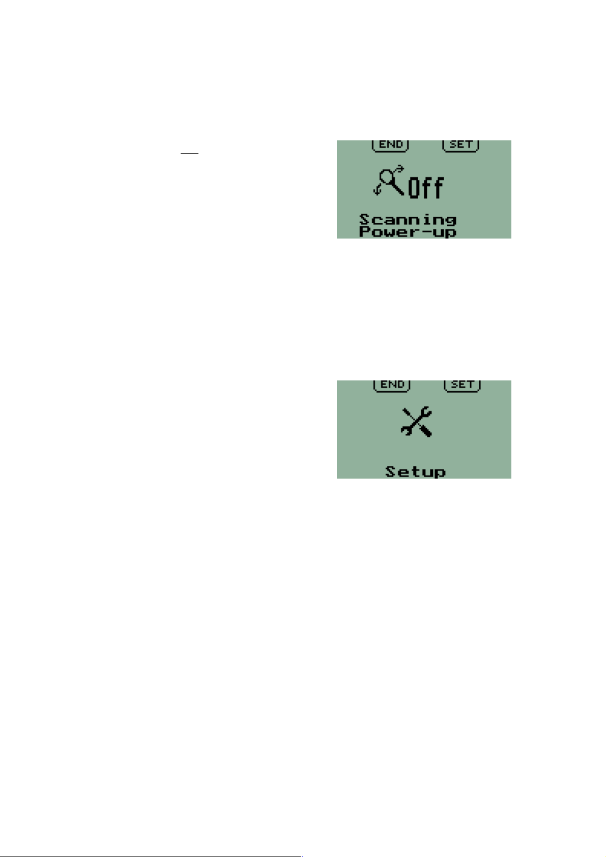
This can help reduce the effects of unwanted noise, in particular at low and
high frequencies. This filter has a sharp cutoff for frequencies below 500 Hz
and above 2.4KHz.
Scanning state at power up
Factory Default: Off
This function sets scanning 'ON' or 'OFF'
when the V6 Transceiver is switched on.
Scanning only applies for active/standby
(Flip-Flop) frequency setting and is always
disabled for direct frequency entry.
Scanning continuously checks for reception
on both active and standby frequencies.
Frequency lists
Setup
This is the entry point to the Second Level
Menu for options and settings relating to
installation of a V6 Transceiver.
17
Page 18
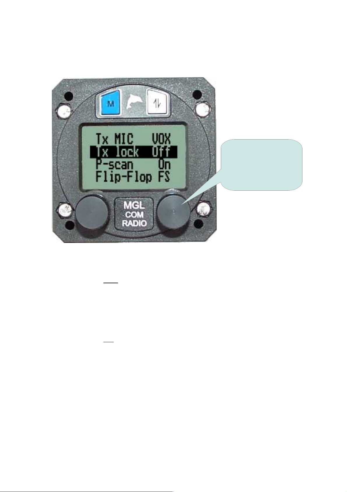
Second Level Menu
The Second Level Menu is accessed by selecting the 'Setup' function from
the First Level Menu.
Rotate the knob to
select the desired
function and then press
the knob inwards to
adjust that function.
TX MIC VOX / HOT
Factory Default: VOX
While transmitting the ambient noise suppression system may remain active -
'VOX' - or the microphone may be continuously live during the time of
transmission - 'HOT'.
TX LOCK ON / OFF
Factory Default: Off
Transmission may be prevented while a signal is being received on the active
frequency.
With TX LOCK 'ON' the PTT is disabled while there is a signal being received
(the squelch is 'open') on the active frequency.
18
Page 19

P-scan ON / OFF
Factory Default: Onf
Enable or disable Priority scanning. Priority scanning only applies to systems
set for Flip-Flop frequency selection.
With Priority scanning ON and scanning enabled, if reception is on the
standby frequency, there is a brief interruption once every second while the
radio checks the active frequency for a signal. If a strong enough signal is
detected on the active frequency, reception switches to the active channel
unconditionally. Once reception on the active channel ends, reception returns
to the standby frequency or scanning resumes.
PTT Configuration
Factory Default: Join
The V6 Transceiver has two PTT inputs. These may be operated
independently or together. PTT1 is associated with the PILOT microphone
and PTT2 with the PAX1 microphone.
For 'Separate', only the microphone circuit associated with its own PTT is
active during transmission – the other microphone is muted.
For 'Join', both microphone circuits are active during transmit and either PTT
may be used.
Flip-Flop FS / Direct FS
Factory Default: Flip-Flop
Selects either 'Flip-Flop' (active/standby) Frequency Selection or 'Direct'
Frequency Selection.
With Direct Frequency Selection only one frequency is displayed – that of the
active channel. There is no standby channel and scanning is not possible.
MIC Levels
Factory Default: 1
This may be configured for a single level to be used for all microphones or
four levels providing independent control for each of the four microphones.
Microphone level is set in the First Level Menu. Screens in the First Level
Menu change according to this setup.
Pilot Isolate configuration
Factory Default: 1 + 3
Two combinations of microphones with PILOT and PAX headphones are
possible. When the 'Isolate' input is active, microphones are associated with
headphone outputs according to the selected configuration. Receiver audio,
sidetone (during transmit), and Auxiliary inputs are all available to both
headphone outputs.
19
Page 20

For '1+3' and 'Isolate' active, the PILOT microphone is associated with the
PILOT headphones and all three PAX microphones are associated with the
PAX headphones.
For '2+2' and 'Isolate' active, the PILOT and PAX1 microphones are
associated with the PILOT headphones and the PAX2 and PAX3
microphones are associated with the PAX headphones.
Auxiliary input configuration
Factory Default: Off
The two Auxiliary inputs are designated Primary ('P') and Secondary ('S').
They may be configured to be 'ON' or 'OFF' in any combination. Pressing the
FREQUENCY knob cycles through four possible arrangements. Auxiliary
levels are set in the First Level Menu. Screens in the First Level Menu
change according to this setup.
Audio output configuration
Factory Default: IC & RX
An Audio output is provided that can be connected, for example, to a Voice
recorder or an external audio panel. The Receiver ('RX') and the Intercom
('IC') may be connected to this output. Pressing the FREQUENCY knob
cycles through four possible arrangements.
Sidetone configuration
Factory Default: ALL
Sidetone is available from the Transmitter and the Intercom. Pressing the
FREQUENCY knob cycles through three arrangements.
CHANNEL spacing
Factory Default: 25KHz
This allows selection of either 25KHz or 8.33KHz steps for setting operating
frequencies. The 8.33KHz setting allows operation in areas using these
channel allocations. All frequency definitions are in accordance with ICAO
standards (ref ICAO Annex 10 Vol 5 § 4.1.2.4)
RESET
This function allows the Transceiver to be reset to 'Factory Default' settings
as listed for each function above. Memory channels and current active and
standby frequencies are NOT affected by the RESET.
20
Page 21

Installation
This chapter describes basic installation options for the V10 Transceiver.
Visit www.MGLAvionics.co.za to download the latest version of this User and
Installation Manual.
General installation notes
Installation should be performed by a qualified aircraft electronics technician.
All wiring external to the V6 Transceiver to conform to relevant aircraft
standards. Flame proof or flame retardant insulation to be used on all wiring.
Installations must conform to local regulations.
All soldering to use acceptable electronic fluxed solder wire. Solder joints are
required to be of high quality to acceptable standards.
It is recommended that shielded cables are used for all audio signal
connections and digital communications links. Using unshielded cables may
result in interference or audio feedback.
Choose suitable power cable of sufficient diameter to carry the maximum
expected current to the V6 Transceiver (1.5A maximum).
It is mandatory to install a 2.5A-5A slow blow fuse or equivalent circuit
breaker in line to the supply of the V6 Transceiver.
Never share power to a Radio Frequency device with sensitive equipment
such as GPS receivers and EFIS systems. Route separate grounds and
power supply wiring to the V6 Transceiver.
Use good quality coaxial cable - RG400 or equivalent. Choose a low loss
cable if the antenna mount far from the Radio.
Ensure that BNC connectors on the antenna cable are fitted correctly. In
particular, ensure that there are no short circuits either inside the BNC
connector or at the antenna end of the cable. An incorrectly fitted connector
may result in poor performance and and may also damage the transmitter.
Never route the antenna cable in a bundle with other wires. Never bend the
antenna cable sharply as this degrades its function as a transmission line.
After installation verify proper operation of the V6 transmitter using a suitable
RF power meter with SWR readout. Ensure that the antenna is well matched
and is able to radiate the available RF power generated by the V6. Reflected
power due to poor antenna match may enter the aircraft ground system and
cause interference with other systems.
Before using the transmitter of the V6 Transceiver, ensure that microphones
are working and levels have been set correctly (in the First Level Menu).
21
Page 22

Planning
The V6 Transceiver is a complex combination of Radio and Intercom and may
be installed with many possible combinations of features. Careful planning of
the installation is necessary based on the configuration of the aircraft and
personal operating preferences.
Choose a position on the instrument panel where the Radio may be clearly
seen and easily reached to operate the controls. Where space behind the
panel is limited, it may be necessary to use special arrangements or fittings
for the connectors. A dimension as small as 150mm/6inches behind the panel
is possible.
The antenna and its mounting are critical to getting the best performance
from the Radio. Choose a suitable position to mount the antenna.
The V6 Transceiver has two PTT inputs. Some aircraft have two control
yokes or sticks, so that two PTT switches may be installed, one for each
position. With two switches installed and the PTT configuration in the Second
Level Menu set to 'Separate', only the PILOT microphone will be 'live' when
transmitting with PTT1 and similarly only the PAX1 microphone with PTT2.
Wiring must be arranged accordingly. For this arrangement, the PILOT
microphone has priority. This means that the PTT1/PILOT microphone will
'take over' transmission if PTT1 is activated, even if the PTT2/PAX1
microphone is transmitting. For an aircraft having a single stick and the PTT
configuration set to 'Join', a single PTT switch may be connected to either
PTT input and both the PILOT microphone and the PAX1 microphone will be
'live' when transmitting.
The Intercom of the V6 Transceiver is provided with a 'Pilot Isolate' facility.
When activated, this allows the two stereo audio output circuits to be
separated or 'Isolated'. When isolated, microphones are associated with
headphone outputs according to the arrangement selected in the Second
Level Menu. Thus the PAX1 microphone may be associated with either the
PILOT headphones or PAX headphones depending on whether 'Mic 1+3' or
'Mic 2+2' is selected respectively. If it is required that the pilot is 'on his own'
when 'Isolate' is activated then the headphones associated with the PAX1
microphone must be wired to the PAX headphone output and 'Mic 1+3'
selected. With this arrangement and the PTT configuration set to 'Separate',
when 'Isolate' is activated PTT2 does not affect the transmitter. Alternatively if
the microphones are to be separated two and two, then the headphones for
the PAX1 microphone are wired to PILOT headphone output and 'Mic 2+2'
selected.
The V6 has two mono auxiliary audio inputs, shown as AuxP and AuxS on the
connector pin-out below. These inputs are prioritized. Thus if an audio input
on AuxS (Secondary) is being passed though to the headphone outputs and
an input is applied to AuxP (Primary) input, this passes through instead and
AuxS is muted completely. AuxP has priority over AuxS. Thus AuxP might be
used for more important alarms or voice alerts (such as Terrain Warning) with
others (such as Oil Pressure) relegated to AuxS.
22
Page 23
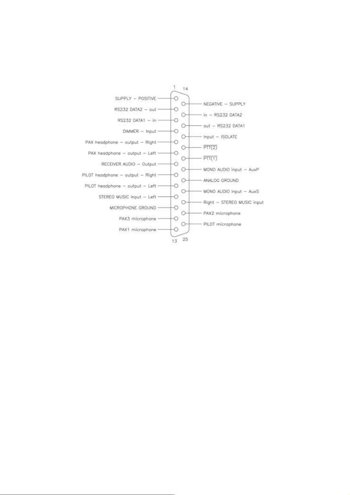
DB-25 connector pin out
A 25 pin female SubD connector on the rear panel provides all low frequency
signal and power connections to the V6 Transceiver. The wiring harness in
the aircraft requires a male DB-25 connector.
A clean DC supply of 12V or 24V nominal is required. Internal protection will
cause the Radio to be switched off if the DC voltage exceeds 32V. The
negative supply lead to the Radio should be terminated at a separate
connection point as close as possible to the negative terminal of the battery.
This will help to reduce interference from other electrically noisy equipment in
the aircraft.
A four microphone intercom circuit is provided with two stereo headphone
circuits. One microphone (the 'PILOT microphone') is intended for the pilot
and the others for passengers. It is possible to connect several microphones
in parallel at each input. In this case it is recommended that identical
headsets be used.
A stereo music input is provided. A suitable jack, such as a 3.5mm stereo
audio jack, should be provided if this input is to be used. An MP3 player may
then easily be connected. For best results, the jack should be insulated from
the airframe and its ground connected to the analog ground pin on the Radio.
Two mono auxiliary audio inputs are provided. These inputs can be used to
connect alarms, EFIS voice alerts and the like.
Two stereo headphone outputs are provided. These are capable of driving 8
ohm speakers or multiple (up to 8) standard aviation headsets. The pilot's
headset should be connected to the PILOT headphone output. The
installation may be wired for mono headsets. In this case, headphone
connections should use only one 'side' of the stereo outputs – all connected
23
Page 24
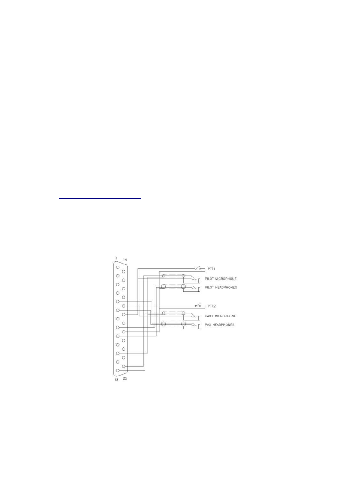
to the same side. The corresponding 'side' of the stereo input can then be
used for music.
Separate analog and microphone grounds are provided. They should not be
connected to supply ground or the airframe as this may introduce audio
interference. Insulating washers or an insulating panel should be used to
mount headset and microphone jacks so that these may be connected back
to the analog and microphone grounds respectively without connecting to the
airframe. Screened cable should be used for microphone connections.
Two PTT inputs are provided. A PTT is activated by connecting the input to
power supply ground or audio ground. Airframe ground may also be
acceptable.
A Pilot Isolate input is provided. This feature may be activated by connecting
the input to power supply ground or audio ground. Airframe ground may also
be acceptable.
Two independent RS232 serial communications ports are provided. These
may be used to connect to two independent EFIS systems for full remote
control of the V6 Transceiver. These ports are equivalent and
interchangeable. A specification for the communications protocol is available
at www.MGLAvionics.co.za.
Typical wiring diagrams
Power supply wiring is not shown. A 2.5A – 5A circuit breaker or fuse must be
installed. This is mandatory. Note the use of shielded audio cable and, in
particular, the connections for the shielding of that cable.
This diagram shows a minimal two place installation with wiring for both
external PTTs and headsets that provide built in PTT buttons.
24
Page 25
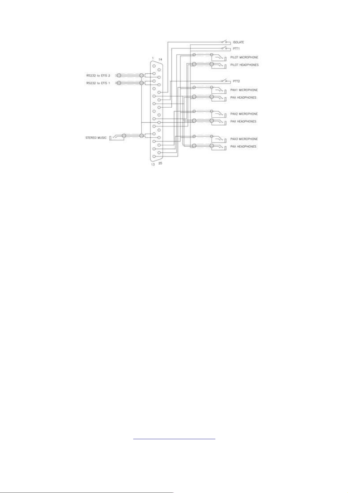
This diagram shows a more complex four place installation in a '1+3'
configuration including 'Pilot Isolate', a stereo music input and remote control
by two EFISs. Note the shielded cables used for the RS232 connections to
each EFIS and that the shields for those cables are only connected at one
end.
Transceiver installation
A minimum installation requires the following:
●
Power supply (typically 12VDC or 24VDC)
●
Pilot headset - microphone and headphones
●
Pilot PTT switch
●
Antenna tuned to the VHF airband connected via RG400 or equivalent
50 ohm coaxial cable
These optional items may be connected:
●
Up to three additional separate headsets
●
One additional PTT switch
●
Stereo music source
●
One or two auxiliary audio sources
●
One or two RS232 connections to EFIS systems (if used)
For more information visit
www.MGLAvionics.co.za
25
Page 26

Specifications
– Subject to change without notification
General
Frequency range RX: 108.000-136.975MHz
Frequency range TX: 118.000-136.975MHz
Frequency control: High resolution fully digital PLL (DPLL) with
precision reference oscillator and
CORTEX M3 micro-controller
Tuning steps: 1MHz, 25KHz or 8.33KHz
Display: Graphic LCD with green backlight – 36 x
20mm
Memories: 99 + 10 x 20 SL30/SL40 compatible
frequency lists
Physical
Configuration: Rear mount - standard Ø57mm / 2¼” cutout
Overall dimensions: W61mm x H61mm x D140mm
W2.3” x H2.3” x D5.5”
Installed depth: 120mm / 4.8” (excl. connectors and wiring)
Operating temperature range: -20ºC ... +55ºC
Weight: 250 grams
Transmitter
Configuration: LDMOS output stage with digital modulator
Output power TX: 6.5W ±10% at 13.8V (specified power
rating)
5W at 12V (typical)
3.5W at 10V (typical - low voltage operation)
Frequency tolerance: <5ppm (-20ºC ... +55ºC)
Modulation: AM (6K00A3E)
Spurious output: < -60 dBc
PTT timeout 35 secs (may be restarted)
Receiver
Configuration: Double conversion super heterodyne
1st IF 45MHz 2nd IF 455KHz
Sensitivity: < 2uV (-101dBm / 50Ω) for 6dB S+N/N
(m=30% 1KHz)
Spurious response: >10mV (-27dBm / 50Ω) – AGC method
Audio output power: >0.5W into 8
headsets)
Ω, 600Ω compatible (up to 8
Page 27

Other
Microphone: Electret
Microphone bias: 8.2V low noise / 1KΩ load
Audio subsystem: Digital with 24bit CODEC, 12KS/s, and DSP
Intercom: Four circuit with adjustable ambient noise
suppression
a) MGL Avionics propriety digital VOGAD
b) Conventional VOX
Music & Auxiliary Inputs: 2Vp-p (max) / 5KΩ load
Serial communications: 2 x RS232, Garmin SL30/SL40 compatible,
MGL EFIS compatible, full remote
control
Power
Voltage: Nominal 13.8VDC Negative ground
Voltage limits: 10.0 ... 32.0VDC (continuous operation, no
damage)
Current RX: <250mA / 13.8VDC (no signal, squelch
closed)
Current TX: <1.5A / 13.8VDC (50Ω load)
RF Exposure
This Transceiver generates RF electromagnetic energy while transmitting. For
compliance with RF exposure limits, the antenna gain should not exceed
0dBd (dipole antenna) and any persons should maintain a distance of at least
0.75m/2.5' during operation.
Do not operate this Transceiver in an explosive atmosphere
FCC Statement
This device complies with Part 15 of the FCC Rules. Operation is subject to
the condition that this device does not cause harmful interference,
This Transceiver has been tested for compliance with CFR 47 parts 2, 15,
and 87 as applicable and is registered accordingly. Any changes or
modifications not expressly approved may void the user's authority to operate
the equipment.
FCC ID: WSJV6 IC No:
27
Page 28

REFERENCE
ADJUST VOLUME or TEST Receiver
Rotate the VOL/TEST knob to adjust volume. Press VOL/TEST knob
to disable squelch for TEST. For Squelch setting enter the First Level
Menu by pressing the MENU button. Press the MENU button again to
exit the menu.
INTERCOM SETUP
Suggested starting point: VOGAD MED level 2 or VOX level 7
Microphone level must be set correctly
Select PTT Join/Separate according to equipment installation
- Refer to First Level Menu
SWITCH ACTIVE AND STANDBY FREQUENCY
Press ACTIVE button.
FREQUENCY ENTRY
SET STANDBY FREQUENCY
Press FREQUENCY knob. Standby frequency selection changes
between MHz and KHz. Rotate the knob to set frequency
SELECT 25KHZ OR 8.33KHZ TUNING STEPS
Second Level Menu function
CHANGE TO CHANNEL ENTRY
Press and hold FREQUENCY knob for two seconds
CHANNEL ENTRY
SELECT CHANNEL
Rotate FREQUENCY knob to set channel
CHANGE TO FREQUENCY ENTRY
Press and hold FREQUENCY knob for two seconds
SELECT SCANNING ON/OFF
Press and hold ACTIVE button for one second. Flashing 'ACT' and
'STB' annunciators indicate if scanning is 'ON'
NB: A 'priority scan' setup is available in the second level Menu
SET 121.5 MHz EMERGENCY CHANNEL
Press and hold ACTIVE button for three seconds. Active frequency will
change to 121.500 MHz
www.MGLAvionics.co.za to download the latest version of this User and
Visit
Installation Manual
 Loading...