

Page 1
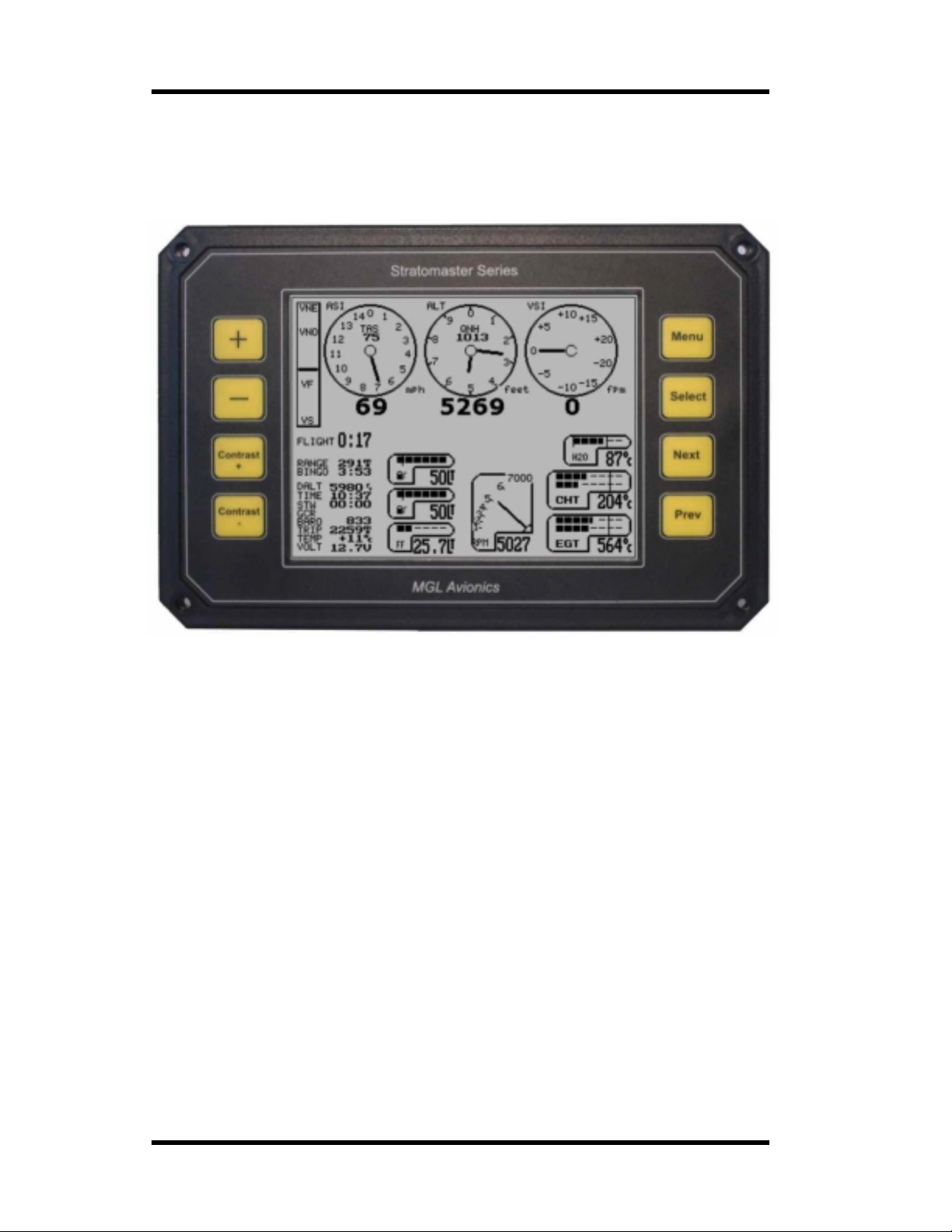
MGL Avionics Stratomaster Ultra Horizon XL Owner’s manual
Stratomaster Ultra Horizon XL
This document is intended for the Ultra Horizon XL instrument panel as
stand-alone or dual panel, with or without engine monitoring.
Owner's Manual
&
Installation guide
MGL Avionics
distributed by DELTA OMEGA
E-mail: [email protected]
Web: http://www.stratomaster.eu
Page 1
Page 2

MGL Avionics Stratomaster Ultra Horizon XL Owner’s manual
THE STRATOMASTER ULTRA HORIZON XL..............................................................................................6
TYPICAL INSTALLATION OPTIONS.............................................................................................................8
SPECIFICATIONS:....................................................................................................................................... 10
GENERAL SPECIFICATIONS..................................................................................................................................................10
TECHNICAL SPECIFICATIONS ULTRA DISPLAY UNIT.......................... ........................... .... ...................10
ALTIMETER........................................................................................................................................................................10
AIRSPEED INDICATOR.........................................................................................................................................................11
VSI................................................................................................................................................................................... 11
TECHNICAL SPECIFICATIONS RDAC...................... .... .................................................. ...........................11
REV COUNTER ...................................................................................................................................................................11
FUEL FLOW SENDER INPUT..................................................................................................................................................11
FUEL LEVEL SENDER INPUTS...............................................................................................................................................11
OIL PRESSURE SENDER INPUT.............................................................................................................................................11
NTC TEMPERATURE SENDER INPUTS...................................................................................................................................11
THERMOCOUPLE TEMPERATURE SENDER INP UTS..................................................................................................................11
POWER SUPPLY.................................................................................................................................................................12
THE STRATOMASTER ULTRA HORIZON XL FEATURES AND FUNCTIONS..........................................13
BASIC SYSTEM FUNCTIONS .................................................................................................................................................13
RDAC EMS FUNCTIONS..................................................................................................................................................... 13
AHRS AND COMPASS FUNCTIONS .......................................................................................................................................14
FLIGHT LOG.......................................................................................................................................................................14
THE ULTRA HORIZON XL MENUS.............................................................................................................16
THE MAIN MENU............................................................. .............................................................................17
FLIGHT…..........................................................................................................................................................................17
PILOT FOR FLIGHT LOG: ......................................................................................................................................................17
VIEW FLIGHT LOG ..............................................................................................................................................................17
THE RANGE CALCULATOR ...................................................................................................................................................17
FUEL LEVEL CALC.:….........................................................................................................................................................18
FUEL ACCU:…...................................................................................................................................................................18
STOPWATCH…..................................................................................................................................................................18
RESET DISTANCE COUNTER ................................................................................................................................................18
TAKEOFF DISTANCE MEASUREMENT.....................................................................................................................................18
Using the takeoff distance measurement function: .............................................................19
HORIZON & COMPASS SETUP..............................................................................................................................................19
AIRCRAFT SETUP ...............................................................................................................................................................19
SYSTEM SETUP..................................................................................................................................................................19
AIRCRAFT SETUP............................... ........................... .................................................. ...........................20
DATE AND TIME..................................................................................................................................................................20
HOBBS METER...................................................................................................................................................................20
MAINTENANCE METER ........................................................................................................................................................20
AIRCRAFT REGISTRATION ...................................................................................................................................................20
SYSTEM SETUP...........................................................................................................................................21
Mode and units setup..........................................................................................................21
Basic operation setup menu................................................................................................21
Move screen items...............................................................................................................21
Enable screen items............................................................................................................21
Primary flight selection ........................................................................................................21
Engine type quick select......................................................................................................21
Rotor craft setup menu........................................................................................................21
Engine detail setup menu....................................................................................................21
Alarm enable setup menu.................................................. .................................................. 21
Sender setup menu .............................................................................................................22
Fuel tank/level sender 1 ............................. .. .......................................................................22
Fuel tank/level sender 2 ............................. .. .......................................................................22
Calibration menu................................................... ... ............................................................22
Probe trouble shooter ....................................... ................................... ......................... .......22
Technical items....................................................................................................................22
Page 2
Page 3

MGL Avionics Stratomaster Ultra Horizon XL Owner’s manual
MODE AND UNITS SETUP..........................................................................................................................22
Altitude display units............................................................................................................22
Local pressure units ............................................................................................................22
Distance/Speed units...........................................................................................................22
Fuel quantity units................................................................................................................23
Temperature units................................................................................................................23
Oil Pressure units................................................................................................................23
MAP Pressure units...................... ... .................. ................... .................. ................... .. ........23
Start of flight detect..............................................................................................................23
Air distance reset.................................................................................................................23
Hour fraction mode..............................................................................................................23
Airtalk This unit is.................................................................................................................23
BASIC OPERATION SETUP MENU............................ ........................... ........................... ...........................23
Flight log RPM Trigger (Take-off RPM)...............................................................................24
Hobbs meter trigger RPM....................................................................................................24
Rev counter scale................................................................................................................24
Fuel low alarm tank 1..........................................................................................................24
Fuel low alarm tank 2..........................................................................................................24
Back light mode...................................................................................................................24
ALT scale.............................................................................................................................24
ASI scale..............................................................................................................................24
Tape resolution....................................................................................................................24
Fuel flow scale.....................................................................................................................24
Stall speed Vs......................................................................................................................24
Flap speed Vf.......................................................................................................................24
Maneuvering speed Vno......................................................................................................24
Never exceed speed Vne....................................................................................................24
Altitude alarm.......................................................................................................................24
MOVE DISPLAY ITEMS ...............................................................................................................................25
ENABLE SCREEN ITEMS............................................................................................................................25
PRIMARY FLIGHT SELECTION...................................................................................................................26
ENGINE TYPE QUICK SELECT................................................................. ..................................................27
ROTOR CRAFT SETUP MENU....................................................................................................................27
Rotor RPM low alarm: .........................................................................................................27
Rotor RPM high alarm:........................................................................................................27
Engine 100% RPM:.............................................................................................................27
Rotor pulses/10 revs:...........................................................................................................28
Rotor 100% RPM:................................................................................................................28
Engine/Rotor RPM display…...............................................................................................28
ENGINE DETAIL SETUP MENU..................................................................................................................28
EGT Channels…..................................................................................................................28
EGT alarm limit… ................................................................................................................28
CHT Channels…..................................................................................................................28
CHT alarm limit… ................................................................................................................29
EGT/CHT bargraph mode ............................ ... ....................................................................29
Oil Pressure limits................................................................................................................29
Oil and Coolant temperature limits......................................................................................29
MAP bargraph range.................... ... .................. .................................................. ................29
Fuel pressure low alarm ......................................................................................................29
ALARM ENABLE SETUP MENU.................................................................................................................30
SENDER SETUP MENU...............................................................................................................................31
Flow sender type.................................................................................................................31
Page 3
Page 4

MGL Avionics Stratomaster Ultra Horizon XL Owner’s manual
Tank mode:…......................................................................................................................31
Range calculation mode… ......................... .. ................................ .. .....................................31
CHT Thermocouple.............................................................................................................32
Coolant temperature probe..................................................................................................32
Oil Temperature probe ........................................................................................................32
Oil pressure sender.............................................................................................................32
Oil pressure max..................................................................................................................32
Pressure resistance…..................... ... .. ................... .................. ................... .................. .....32
Fuel pressure range ............................................................................................................32
Fuel pressure port................................................................................................................32
912/914 CHT type.............................. ......................... .........................................................33
The programmable temperature probe ...............................................................................33
The MGL precision temperature probe ...............................................................................33
FUEL TANK/LEVEL SENDER SETUP 1 AND 2..........................................................................................34
Notes on Slope error ............... ... .................................. .................................................. .....35
CALIBRATION MENU................................................................................ ..................................................36
Airspeed calibration.............................................................................................................36
Altimeter calibration.............................................................................................................36
VSI calibration......................................................................................................................36
Reset ASI and VSI to zero...................................................................................................37
Rev counter: Pulses per 10 revs.........................................................................................37
Fuel flow K-Factor............................................ .................................................. ............... ...37
Ambient temperature...........................................................................................................38
MAP calibration........ .................................................................................. ..........................38
PROBE TROUBLE SHOOTER..................... ........ ... ........ ........ ... ........ ........ .... ....... .... ........ ........ ... ..... ...........38
ULTRA HORIZON XL CONFIGURABLE DISPLAYS...................................................................................40
THE ALTIMETER.................................................................................................................................................................41
THE AIR SPEED INDICATOR .................................................................................................................................................42
THE VSI INDICATOR ...........................................................................................................................................................43
THE VSPEED INDICATOR..................................................................................................................................................... 43
THE REV COUNTER.............................................................................................................................................................44
About rev counter pickups.................... ...............................................................................44
EGT AND CHT THERMOCOUPLE DISPLAY.............................................................................................................................45
COOLANT TEMPERATURE INDICATOR ................................................................................................................................... 46
OIL TEMPERATURE AND OIL PRESSURE INDICATOR ...............................................................................................................46
The oil pressure indicator....................................................................................................46
The oil temperature indicator...............................................................................................47
MANIFOLD PRESSURE INDICATOR........................................................................................................................................ 47
THE FUEL FLOW AND FUEL LEVEL INDICATORS ......................................................................................................................47
The fuel flow indicator..........................................................................................................47
The fuel tank level indicators.............................................................................. . ................48
FUEL PRESSURE INDICATOR................................................................................................................................................ 48
NUMERIC INFORM A T ION DISPL AYS ....................................................................................................................................... 49
DALT (DENSITY ALTITUDE).................... ... ................... .................................................. ..49
BARO (BAROMETER)........................................................................................................49
TIME....................................................................................................................................49
FLIGHT................................................................................................................................50
GCR.....................................................................................................................................50
TEMP...................................................................................................................................50
TRIP.....................................................................................................................................50
VOLT ...................................................................................................................................50
RANGE................................................................................................................................50
BINGO.................................................................................................................................51
STW.....................................................................................................................................51
HOBBS METER...................................................................................................................51
MAINTENANCE METER.....................................................................................................52
GCR (Glide or climb ratio)...................................................................................................52
OPERATING THE ULTRA HORIZON..........................................................................................................52
Page 4
Page 5

MGL Avionics Stratomaster Ultra Horizon XL Owner’s manual
IFR DISPLAYS USING THE AHRS COMPONENTS...................... ........................... ........................... ........53
AHRS mode indicator................................................... ... ....................................................53
Slip indicator........................................................................................................................53
Turn indicator.......................................................................................................................53
The horizon display .............................................................................................................53
COMPASS AND HORIZON SETUP.............................................................................................................54
HORIZON SETUP................................................................ .........................................................................54
Set Bump factor...................................................................................................................54
Set Slew factor.....................................................................................................................54
Finding the right filter values....... .. ............................................................................... ... .....55
Attitude mode......... .. ............................................................................................................55
Attitude determination modes.................. ............................................................................55
IMU attitude determination ..................................................................................................55
Magnetometer based attitude determination.......................................................................55
Set inclination......................................................................................................................56
COMPASS SETUP.......................................................................................................................................57
Heading mode Magnetic / True...........................................................................................57
Local variation......................................................................................................................57
Tilt compensation mode......................................................................................................57
Enter Deviation SET mode..................................................................................................58
Clear Deviation calib................ ................................................ .. ..........................................58
SET NORTH, SOUTH, EAST, WEST......................................................................................................................................58
USING THE DEVIATION COMPENSATION FEATURE .............................................................................. 58
CARING FOR THE STRATOMASTER ULTRA..................................................... .......................................61
PITOT TUBE .......................................................................................................................................................................61
CLEANING .........................................................................................................................................................................61
CALIBRATION.....................................................................................................................................................................61
ALTIMETRY..................................................................................................................................................61
TRUE AIRSPEED (TAS)...............................................................................................................................63
WARRANTY..................................................................................................................................................64
DISCLAIMER................................................................................................................................................64
INSTALLATION MANUAL FOR THE STRATOMASTER ULTRA “H”........................................................66
INTRODUCTION.................................................................................................................................................................. 66
THE ULTRA HORIZON XL REAR PANEL...................................................................................................67
Rear panel connections and items:.....................................................................................67
CONNECTIONS TO THE ULTRA................. .... .................................................. ..........................................68
Power to the Ultra.................. .. .................................. . .. ... ....................................................68
Ambient temperature sender...............................................................................................69
External, visual alarm indicator............................................................................................69
External, audible alarm...................................................... ... ...............................................70
Pitot tube and static port......................................................................................................70
GETTING STARTED WITH THE ULTRA.....................................................................................................72
Page 5
Page 6
MGL Avionics Stratomaster Ultra Horizon XL Owner’s manual
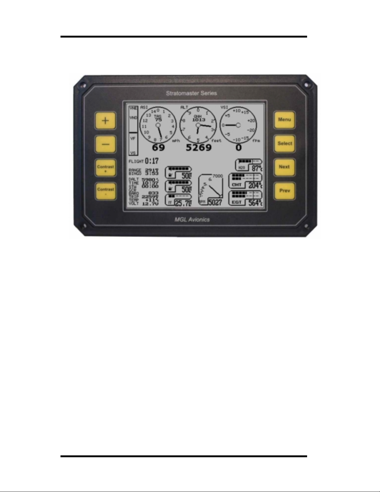
The Stratomaster Ultra Horizon XL
A typical setup including EMS (engin e mon ito r ing syst em)
The Strato mast er Ultra Horizon XL is a digital multifunction instrument designed for use in
ultralight, m icrolight, experimental and homebuilt a i r craft as wel l as any aircraf t that permit
use of such instrumentati on und er gen eral or speci al ope rat i ng per mit s.
The Ultra is designed around a tr ansflective 5.7” monochrome display panel with a w hite LED
backlight. Unlike current technology color displays, the mo nochrome panel is suited for
operation in direct sunlight making it the only viable choice for many small aircraft
applications. The panel does not need to be shaded a nd is capable of pr oducing a clearly
readable image even in very bright light conditions, with the light falling directly onto the
panel.
The Ultra Horizon XL replace s the following previous product r eleases:
1) Stratomaster Ultra L
2) Stratomaster Ultra X
3) Stratomaster Ultra HL and HX
4) Stratomaster Ultra R L (Rotorcraft).
The Ultra Horizon XL is a fully us er configurable panel that can be used as primary flight
instrument ati on display, engine moni tor or both.
The Ultra provides two disp lay pages, each page can be configured by the user, choosing
from a selection of more than 50 instruments and display items.
Each item on the screen may be placed where the user wants it and most instruments
provide several different display options. For example you can choose between analog
altimeter and a tape based altimeter amongst other choices.
Page 6
Page 7

MGL Avionics Stratomaster Ultra Horizon XL Owner’s manual
Panels may be designed on the Ultra itself or using a Microsoft Windows based panel design
program avail abl e fo r free download from www.MGLAvionics.co.za
Two Ultra pane ls may be connected to each other in a cockpit allowing Pilot/Co-Pilot displays
providing redundancy in case of failure.
The Ultra Hor izon XL can be connected to the following sensor sources:
RDAC A four channel thermocouple engine monitor
RDAC B twelve channel the rmocouple engine monito r
RDAC C four channel thermocouple engine monitor with manifold pressure sensor
RDAC D twelve channel thermocouple engine monitor with manifold pressure sensor
SP-1 two-axis magnetic compass.
SP-2 three axis, tilt compensated m agnetic compass.
SP-3h horizon / turn&bank sensor.
SP-3hc AHRS (attitude and heading reference system) , includes a three ax is tilt
compensated magnetic compass.
Details on either of the above can be found in the relevant manuals. Please browse the MGL
Avionics website www.MGLAvionics.co.za
Most civil aviati on authorities p er m it installation of the Ultra instrument as a secondary
instrument on ce r tified aircraf t. Please ensure that you obtain the required permits or STCs
before operating this instrument on a certified aircraft.
The Stratomaster Ultra has been designed with the following objectives in min d:
a) Provide a cost effective solution for a complete instrumentation system for small aircraft.
b) Provide inst rum en t a ti on with uncompromisin g accuracy and range .
c) Provide a display unit with a shape and form factor suitable for installation into most small
aircraft panels an d pods.
d) Provide a display with the b est possible viewing qualities over a wide temperature range,
taking into account operation in bright sunlight as well as low light conditions.
e) Provide a system that offers long term stability and reliability with specific attention to low and
medium frequency mechanical vibr ations and shock loads such as when taxing a light aircra ft
on rough ground.
f) Provide a system that is easy to install and that maintains its usefulness should a different
type of engine be installed in the aircraft.
The objectives have been achieved using the latest available embedded processing devices,
which result in a drastic reduction of the amount of individual components required. This has
a direct effect on improving reliability and reducing EMI (Electromagnetic interference), long a
bane of digita l systems.
Should you be using a RDAC X engine monitoring system, please refer to the manual that
was included with your RDAC for specific installation instructions.
for detaile d information on these sensor packages.
.
Page 7
Page 8
MGL Avionics Stratomaster Ultra Horizon XL Owner’s manual
Typical installation options
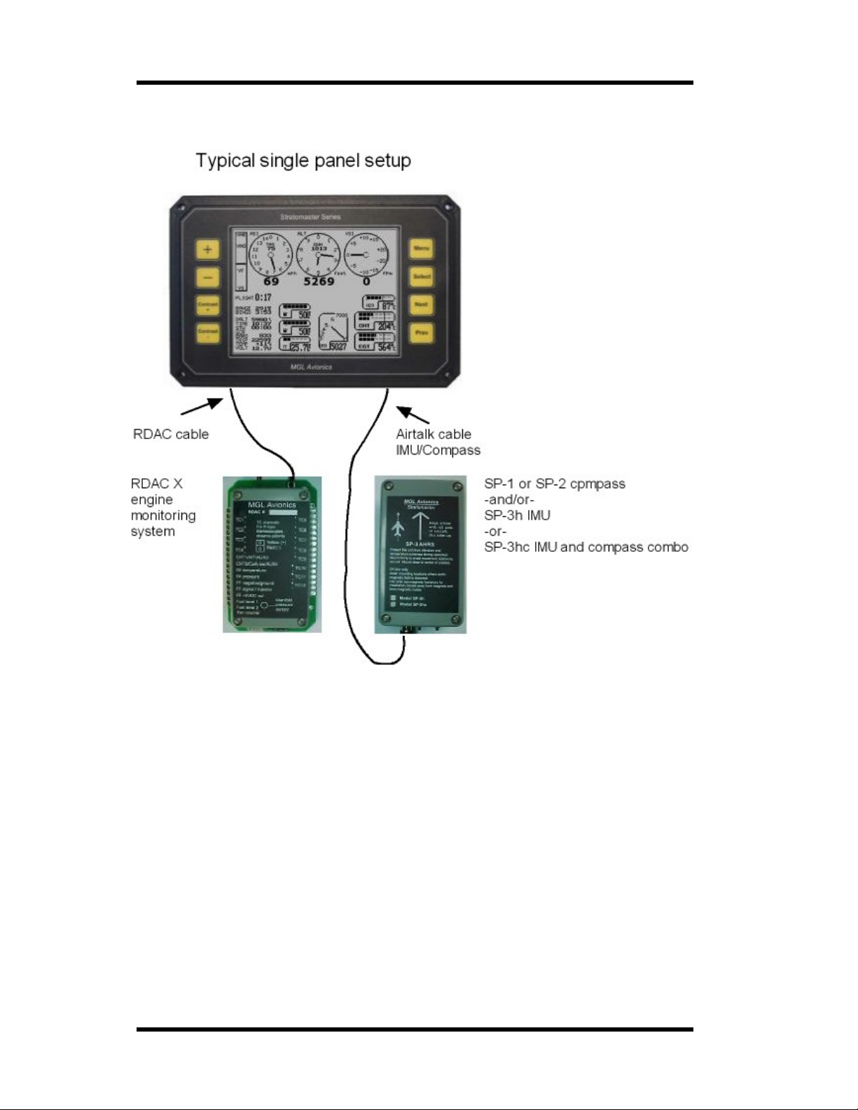
The above picture shows a typical single panel installation with an RDAC X engine mon itor and
SP-x compass or IM U sensor packa ge.
Both RDAC and SP-x sensor packa ge ar e optional compon ents, although most installations
make use of the RDAC engine monitoring system.
Page 8
Page 9
MGL Avionics Stratomaster Ultra Horizon XL Owner’s manual
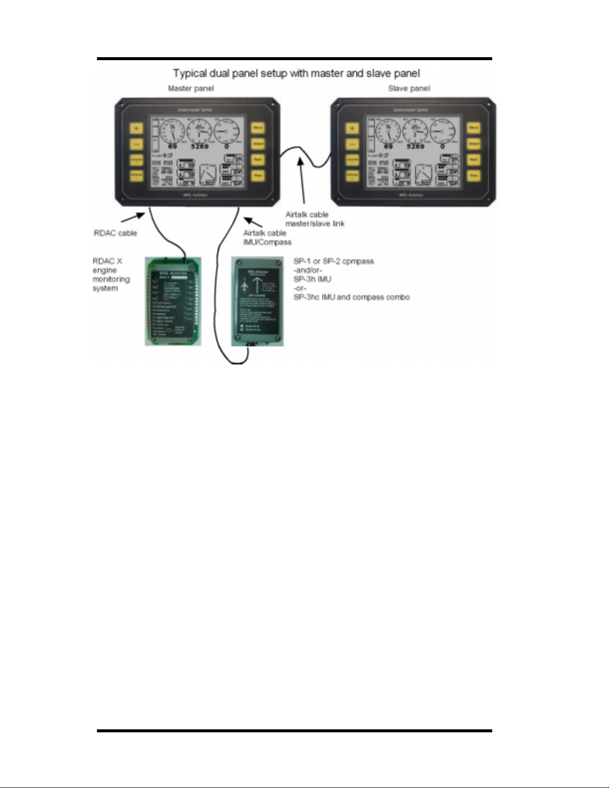
The above picture shows a dual pa nel setup. Two id entical Ultra panels are used . The left panel
is configured as master (setup in the mode menu) and the right panel is the slave.
The slave panel obtains all eng ine and other instrument data from the master panel via the airtalk
link.
RDAC engine monitor and SP-x com pass or IMU sensor packages are optional componen ts. It is
not strictly required that an Ultr a system has an engine monitor, although most installations d o.
For the above installation, the RDAC and tub ing for airspeed and altimeter would normally be
connected to both systems. This makes it pos si ble to change the master/slave assignment
should this be required.
For a dual panel layout, two distinctly differen t operating modes can be selected. The first is a
mode where both panels operate autonomously but will share the same engine mo nitoring RDAC
– the RDAC is wired to both pane ls. Also, the SP-3 is shared.
In this mode, the only interaction between the two panels is the adjustment of local pressure for
the altimeter. Yo u can change t he pressure setting on any panel and the other will follow.
The second dual panel mode uses one panel as passive and the other as active panel. The
active panel transmits all relevant data from altitude and airspeed to engine monitoring data to
the passive panel. The passive panel does not acquire any data of its own but uses the data from
the active panel instead.
Dual panel modes are setup in the Mode and Units setup menu.
Page 9
Page 10

MGL Avionics Stratomaster Ultra Horizon XL Owner’s manual
SPECIFICATIONS:
General specifications
Ultra Display unit:
Size: 202x135 mm. Moun ting depth 95mm (including co nnectors and wiring). Pan el cut out
196x122 mm.
Weight: 980 gram s. Excluding external senders, including RDAC unit.
Power supply requirements: 12V DC nominal. Range 6.5V DC to 28V DC. Internally
protected to 33 V DC.
Current consum p tion: 80 mA with back light at 13.8V DC. Exc l udes current requirements of
external se ns o r pac kag es if a ny .
External temperature sensor input: Optimized for National Semiconductor LM335
temperature sender.
Alarm output: Active low pull down transistor output suitable for switching of lam ps and LEDs
with droppin g resistors. Ma ximum current 0 .5A DC.
Air-talk link: Two Air-talk links are provided. These are used to connect to other Air-Talk
compatible devices. Standard aud io RCA cable and connectors are us ed as medium. Air-talk
is intended as a short distance, multi m aster communications link allow ing Air-talk compatible
devices to share infor mat io n. The Strato ma ster Ultr a uses the Air- talk link to connect to
another Stratomaster Ultra a PC, Flight data recorder (black box), and key download devices
(for transfer of the log to a remote PC).
The airtalk link is also used to connect either SP-1, SP-2 or SP-3 attitude and heading sensor
packages.
Rotor speed sensor input: This input is used for the split rotor speed and engine power
instrument. Intended for rotor craft such as Gyro planes and helicopters.
Technical specifications Ultra display unit
Altimeter
Range 0-40 000 ft (12 195 m), 1ft (or 1 m) dynamic resolution, 7.5 ft (or 2 m) static resolution
at sea level. Dynamic resolution applies with the aircraft in flight. Dynamic resolution is
measured by mathem a tic all y evaluating the turbulence created around the airc r a ft.
Basic accuracy at 20 degrees C (68 degrees F) +/- 30 ft (9 m) based on calibration to
mercury manometer at +/- 1 mb (0.0295 Inch of Hg).
Maximum theoretical error factor +/- 1.5% over temperature range 0-40 degrees C (104
degrees F). Typical error factor ove r temperature range 0-40 degrees C (104 degrees F) is
less than 0.5%
Note: The altimeter can be operated to altitud es above 40 000 ft (12 195 m). Rang e and
accuracy above the 40 000 ft (12 195 m) level are dependant on individual units. The
achievable range is in the regi on of 45 000 ft (13 720 m) to 60 000 ft (1 8 293 m) depend ing
on manufacturing tolerances of the pressure sensor.
Page 10
Page 11

MGL Avionics Stratomaster Ultra Horizon XL Owner’s manual
Airspeed indicator
Range 0-250 mph (402 Kph or 217 Knots), 1 mph (1 Kph or 1 Knot) resolution. Theoretical
accuracy 1% at 20 de grees C (68 degrees F), subject t o installation of pitot tube and a irflow
pattern arou nd aircraft.
VSI
Range +/- 9 990 ft. (3 045 m) Resolution truncated to 10 ft/minute (5cm per second).
Internally 1 ft/minute. Accuracy +/-5 %, Please note: The VSI is compensated for altitude.
Minimum display resolution is as low as 10 ft/min (5 cm per second) with a +/- 2 000 ft (610 m)
maximum reading.
Technical specifications RDAC
Rev counter
Range 0 to 9 999 revs. Resolutio n is dependant on rev counter setup in instrument.
Accuracy: +/- 0.0005% + resolution.
Fuel flow sender input
Accuracy of measurement is +/-0.05% subject to accuracy of fue l flow sender used. Example
sender is MGL Av ionics dual range fuel flow sender: +/- 3% uncalibrated, typically less than
1% calibrated.
Fuel level sender inputs
Intended for use with resistive fuel level probes. Can be used with most capacitive type
probes as well.
Input consists of a 1000 ohm pullup resistor to a 5 V DC source.
Measurement accuracy of input: +/-2%. Overall measurement accuracy of fuel level is subject
to quality and installation of chosen fuel level sender as well as com plexity and for m of tank
shape.
Using the prescribed calibration procedure we find we can calibrate within 5% of actual level
for most tank shapes.
Oil pressure sender input
1500 ohm pullup resistor to 5VDC s our ce. For use with typical VDO and similar resistive oil
pressure sender s. Supports senders that increase resistance with pressure as well as
senders that decrease resistance with pressure. Supports resistance ranges from 50 to 1000
ohms full range.
NTC temperature sender inputs
Measurement accuracy +/- 2% subject to accuracy of sender. Note: Senders are
manufactured with a tolerance of up to +/- 20%.
Thermocouple temperature se nder input s
Measurement accuracy +/- 1%. The thermocouple amplifier system used is highly stable and
long-term drift elimination is achieved by using a chopper stabilized system. The system
Page 11
Page 12

MGL Avionics Stratomaster Ultra Horizon XL Owner’s manual
employed features full, accurate cold junction com pensation and bow voltage correction. The
system is further highly immune to received EMI from high powered ra dio transmitte rs.
Power supply
The Stratomaster Ultra unit is optimized and intended for operation on a 12V DC supply such
as a motorcycle battery. However, it can be operated on any power supply down to about 6.5
volts as well as air c r af t power supplies of 24 or 28V DC.
Current consumption may vary slightly between units but is typically in the region of 40 mA
without display back light and 80 mA with display bac k ligh t.
Current consumption reduces as su pply voltage incr eases.
The unit is intern ally protected against temporary over voltage loads such as those that can
be produced by a cranking starter motor.
It is advisable to power the unit via a fuse or circuit breaker. A fuse rating of 1A (slow blow) is
recommended. Generally it is accepted to use cir cu it breakers that can be reset during flight
should the need arise. Ordinary fuses are not recommende d for aircraft use.
Page 12
Page 13

MGL Avionics Stratomaster Ultra Horizon XL Owner’s manual
The Stratomaster Ultra Horizon XL features and functions
Basic system functions
• Altitude to 40 000 ft (12 195 m ) calibrated, 1ft dynamic resolution
• Airspeed ASI analog and digital, TAS digital
• Stopwatch
• Glide and climb ratio to 1/99
• QNH 960 to 1 060 mb (28.3 - 31.3 Inch of Hg)
• QNE 1013 mb quick select (29.9 Inches of Hg)
• Time of day, Date for flight log entries
• Air time since take-off (or lesson time)
• Ambient temperature using external sensor
• Up to two Fuel level using flow sender or optional level sender
• Fuel flow usi ng optional flo w sender
• Current range estimate (range at current sp eed and fuel burn)
• Fuel bingo estimate (time unt il tank empty)
• Range calculator using manually entered ground speed
• Air distance made good
• Voltage. Supply to unit. Usually 12V battery.
• VSI +/- 9 990 ft/ m inute (50.7 meters per second) range
• Flight log storing up to 200 entries
• Hobbs meter, presetable to current engine time
• Density altimeter
• Barometer for ambient pressur e
• Aircraft registration number display
• Maintenance timer
• Warnings for en gine temper ature, speed high, speed low, maximum altitude, low fuel
level, etc
• Alarm output to switch a warning lamp
• Audio alarm output to drive a panel speaker or low level output for alarm tone injection
into a suitably equipped he adset or intercom system.
• Master and slave modes for dual instru m ent setup
• Measuring take-off run to 50 ft (15.24 m) above ground level
• Artificial horizon (requires SP-3h, SP-3hc)
• Slip indicator (requires SP-3h, SP-3 hc)
• Rate of turn indicator (requires SP-3h, SP-3hc)
• Compass (requires SP-1, SP-2 or SP-3hc)
• Air talk link for connection to:
A) PC’s and Laptops using optional cable
B) Stratomaster “Black Box” flight recorder
C) Stra tomast e r Ultra secon dary instrument
D) Key ring flight log download device
E) Compass and AHRS sensor pack ages
RDAC EMS functions
• Four or twelve channel thermocouple amplifier, high resolution chopper stabiliz ed system
with full cold jun ction compensat ion and bow voltage correction to laborator y st andards.
The inputs can accept K-type or J-type thermocouples (selectable via provided menu
functions)
• Oil and Water temperature NTC input compatible with most oil temperature senders and
the MGL water te m perature sender. Also accepts MGL precision semiconductor senders
for water and oi l temperature.
Page 13
Page 14

MGL Avionics Stratomaster Ultra Horizon XL Owner’s manual
• Universal rev counter input. Can be used on a wid e variety of en gines using a variety of
interface methods.
• Fuel flow sender input. Can be used with most commercial liquid flow senders.
Calibration v ia provided menu functions.
• Oil pressure sender input. Accepts most com mercial oil pressure senders includi ng those
from VDO.
• Fuel level sen der input with extensive calibr ation functions provided to allow direct
readout of fuel quantity corrected for tank shape and sender tolerances.
• LM335 sensor based temperature sender to indicate ice warning. The sender is normally
fitted to the out side of a carburetor, in close proximity to the throttle slider or valve or in
the intake airflow.
The EMS included with the Ultra “H” provides f or a wide variety of engines and the display
unit can be configured in many different ways as outlined under the “Device setup menu”.
AHRS and compass functions
Available funcions in this category depend on the capabilities of the sensor package
connected. The following list shows funct i ons available with the SP-3hc package.
• Bank /Pitch attitude display. This display resembles the artificial hor izon as found on typical
IFR panels. The attitude di splay is not restricted to a range of bank or pitch and is thus
fully aerobat ics capab le .
• Bank&Turn display. This consits of Rate 1 markers (2 minute standa rd r ate turn at 20
degrees bank) and a traditional “ball slip” display.
• Comp ass or gyro compass heading. Th is depends on the abilities of the connected
package.
Flight log
Perhaps one of the most useful features of the Stratomaster Ultra instrument is the ability to
record a flight log.
You can setup your Stratomaster Ultra to record a log entry in one of the following ways:
1. Automatic flight log norma l aircraft. This will automatically detect the start of a flight and
end of a flight. The unit uses engine revs in combination with airspeed to detect a flight.
This is the way most pilots pre fer to operate the Stratomaster U ltra.
2. Automatic flight log rotor craft. This operates sim ilar to above but a ir speed is not taken
into account. Instead, rotor speed above 70% of the 100% s etting is used to mark
possible start of a flight. If you select the split rotor/engine RPM display this mode is
automaticall y select ed.
3. Manual fligh t log. In this case the pilot manually starts a flight and ends it. This mode is
used mainly if no r ev counter input t o the instrument is available.
The Stratomaster Ultra will log all flights of longer than one minute. Any flights with less than one
minute accumulated time ar e not stored in the log.
The Stratomaster Ultra will store the last 200 f lights in the log.
At the end of a flight, the pilo t number selected in the main menu wil l be writ ten to the log entry
for the flight. This can be used to log airtime of several pilots, for example with aircraft sharing
schemes. The log can be viewed at any time. Please also note that the log may be dow nloaded
to a PC using a direct cable connection or key-ring download device (optional extras).
The following information pertaining to a flight will be logged:
Page 14
Page 15

MGL Avionics Stratomaster Ultra Horizon XL Owner’s manual
• Date (DD/MM) of take-off
• Take-off time.
• Flight time. Displayed in either hours and minut es or hours and fraction of hours
depending on setup.
• Highest altitude reached (In ft or meters depending on setup)
• Maximum airspeed obtained. Displayed airspeed depends on whether ASI or TAS is
selected. (Displayed in kilometers, miles or knots depending on setup).
• Hobbs meter reading at end of flight/lesson (Displayed in either hours and minutes or
hours and fracti on of hours depending on setup)
• Pilot number
Page 15
Page 16
MGL Avionics Stratomaster Ultra Horizon XL Owner’s manual
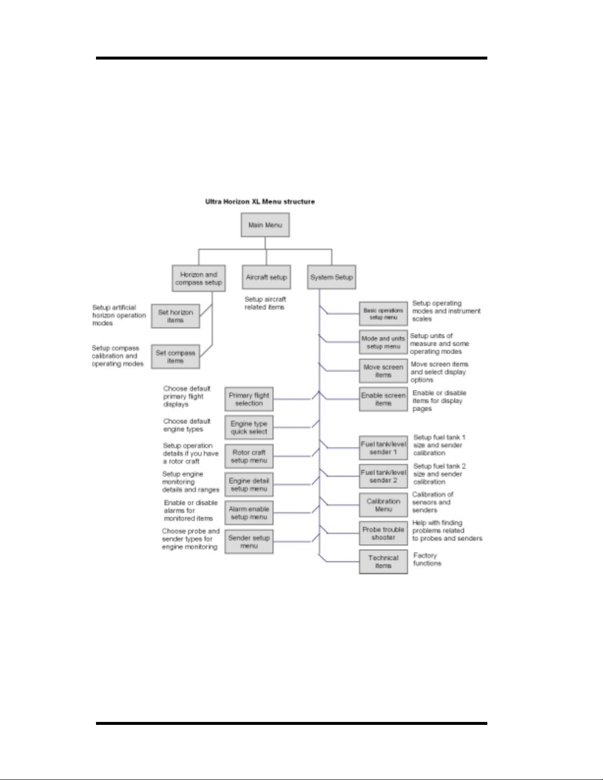
The Ultra Horizon XL menus
Nearlt all of the Ultra Horizons functions are accessed via menus. The menus are easily
navigated. Press Menu from any of the two main display pages to enter the “Main Menu”. From
here you have access to several functio ns and three sub menus.
Use the “Prev” and “Next” buttons to choose a menu item and press “Select” to enter the function
or sub menu. Some functions accessib le in the Main menu can be controlled directly with
“Select”, “+” or “-“ as indicated in the item itself.
The following graphic shows th e menu structure of the Ultra.
Page 16
Page 17
MGL Avionics Stratomaster Ultra Horizon XL Owner’s manual
The main menu
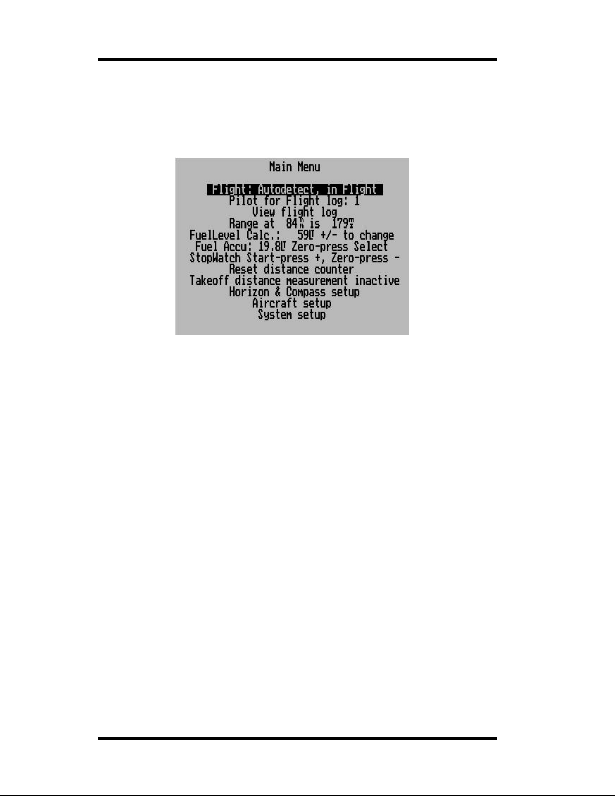
The main menu is entered fro m t he mai n instrument display by pressing the menu key .
The main menu is your route to accessing several additional functions as well as activating the
many setup and configuration menus and functions.
Flight…
This menu entry shows you your current flight detect status if you have automatic flight detect
enabled. The above displa y would be shown if you are in flight.
If you are using manual flight start and stop, then this menu entry will allow you to start and stop
flights. In this case automatic flight detect is disabled.
We recommend th at you use automatic flight dete ct.
Flight detection is relevant for logging of flights for your built in flight log.
Pilot for flight log:
When a flight ends the flight information is written to the built in flight log. Each log entry con tains
a field contain i ng the pilot number as selected in this field.
This can be used to keep track of flight times for several pilots when the aircraft is shared.
View Flight Log
This function allows you to view the logged flight details. The Ultra will maintain a log of the last
200 flights. The log can also be downloaded to a PC using the free flig ht log program f r om MGL
Avionics (download from the website www.MGLAvionics.co.za
direct cable connection using an airtalk to PC c able or you can use a M GL Avionics flight log
download ke y device to transfer flight log data from yo ur aircraft to your PC at home.
). The log can be download ed b y
The range calculator
The Stratomaster Ultra includes a useful range calculator if you have at mini m um a fuel flow
sender.
Page 17
Page 18
MGL Avionics Stratomaster Ultra Horizon XL Owner’s manual
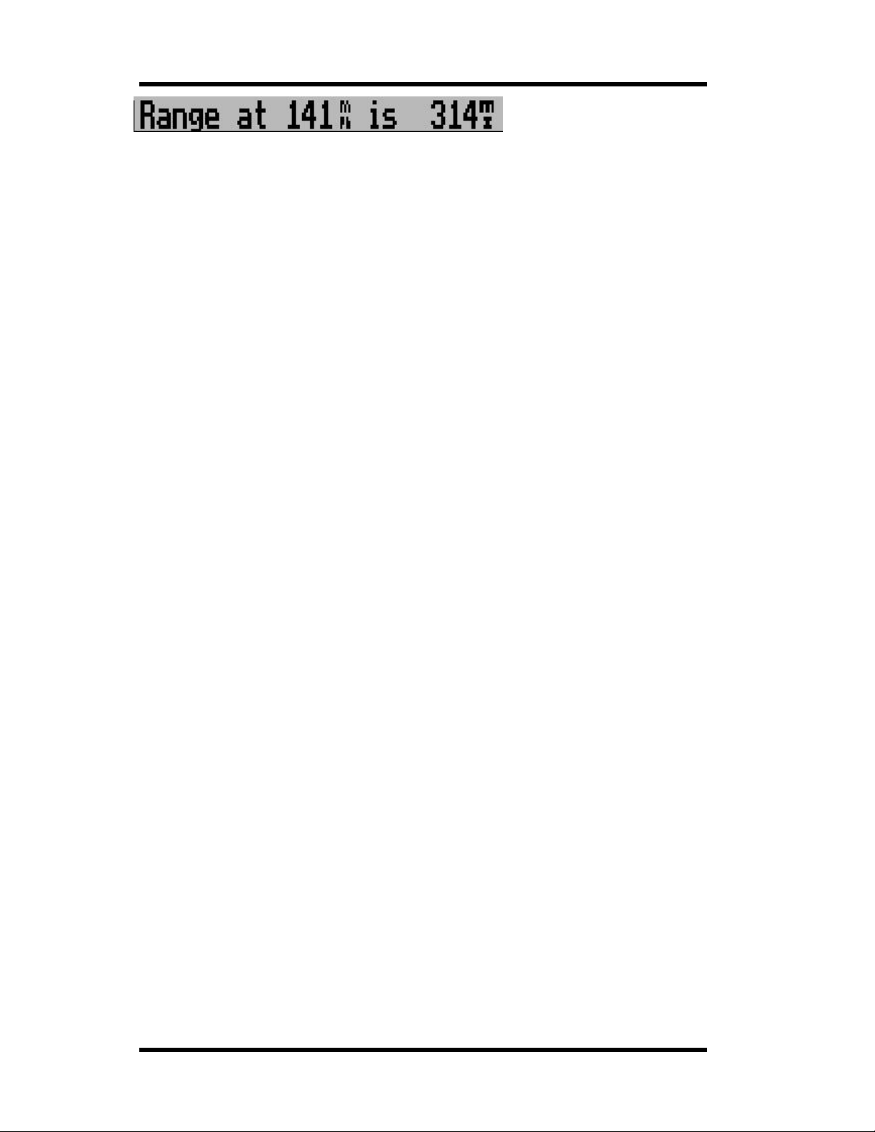
The range calculator defaults to your current TAS (true airspeed) as shown on the airspeed
indicator face (bottom right corner). This agrees with the range calculation as shown if you have a
range display enabled.
Move the menu highlight to the range calculator as shown above and you can now change the
speed using the + and – keys. You might want to enter your current ground speed as shown on a
GPS for example.
Range will be cal cu lated using your cu rrent fuel flow readi ng as a base as well as the current fuel
level.
As with all instrument readings, it is the pilot’s responsibility to use these figures responsibly.
Be certain that fuel level reflected is correct and that fuel flow as shown is calibrated and
trustworthy.
The range cal culator must never be used t o stretch a marg inal fuel range situation. It is the
pilot’s responsibility to work on actual fuel burn figures as well as loaded fuel quantities at
all times. Good airmanship includes always planning a flight with sufficient fuel reserves.
Fuel level Calc.:…
This menu entry allows you to adjust your calculated fuel level. You can use a c alculated fuel
level if you have a fuel flow sender connected.
Set the calculated fuel level equal to your loaded fuel whenever you fuel or de-fuel your aircraf t.
You can set either of the two fuel level displays to show you the calculated fuel level instead of a
physical fuel level obtained from a fuel level sender.
Fuel accu:…
This entry shows your accumulated fuel burn if you have a fuel flow sender connected. You can
reset the accumulator b y moving the hi ghl ig ht to this ent r y and then pressin g “Sele ct”.
Stopwatch…
This function allows you to start, stop and reset the built in stopwatch. To view the stopwatch, you
need to place the stopwatch display item onto one or both display pages.
Reset distance counter
This function r esets the airspeed based trip counter to zero. Place the highlight on this item and
then press “Select” to set the trip counter to zero.
Note: you can set up the system to clear this counter to zero every time you start a flight. This is
done in the Mode and units setup menu.
To view the dist ance trip counter you need to place the trip d isplay item onto one or two display
pages.
Takeoff distance measurement
Page 18
Page 19

MGL Avionics Stratomaster Ultra Horizon XL Owner’s manual
This interesting function will measure your takeoff distance based on the distance you have
traveled through a b od y of air to the po int wh ere your altitude is 50 ft higher the n at the point you
started. This corresponds to standard 50 ft obstacle takeoff distance measurements.
The distance shown will be fairly ind ependent on wind factors and correspon ds closely to the
zero windspe ed takeoff distance when use d on a tar runway.
For grass runways the distance will be influenced by the additional friction between your aircrafts
wheels and the grass runway. T his tends to make your takeoff run measured shorter if you
takeoff into significant wind when compared to zero windspeed using the same runway. Please
note, we are talking about di stance traveled though a moving body of air, not actual distance
traveled on the ground.
Using the takeoff distance measurement functi on:
Taxi to the start of your tak eoff run and finish your pre-t akeoff check s. When you are ready to roll,
move the highlight to this entry and press select. The display changes to:
Start your takeoff run…
Start your takeoff run immediately. Once you have exceeded an airspeed of 16mph the display
changes to:
Rolling…
Once you have exceeded 50 ft altitude gain the display changes again and will display your
takeoff distance:
Takeoff distance is 135m (example distance in meters)
Please note:
Once you have star ted the tak eoff distance meas ur ing mode, you may change back to the main
displa y s cr e e n .
Once you have reac hed a safe altitude, switch back to t he menu to read your takeoff distance.
Horizon & Compass setup
This entry branches into the horizon and compass setup menu. Yo u will only need these
functions if you have a SP-1 or SP-2 compass or SP-3h or SP-4hc I M U system.
The Horizon and Compass menu is described lat er in this manual.
Aircraft setup
This function branches into a menu that allows you to set items such as date/time, hobbs meter
etc.
System setup
This selection branches into the System setup menu. Here you will find all the items required to
customize your Ultra to your needs.
Page 19
Page 20
MGL Avionics Stratomaster Ultra Horizon XL Owner’s manual
Aircraft setup
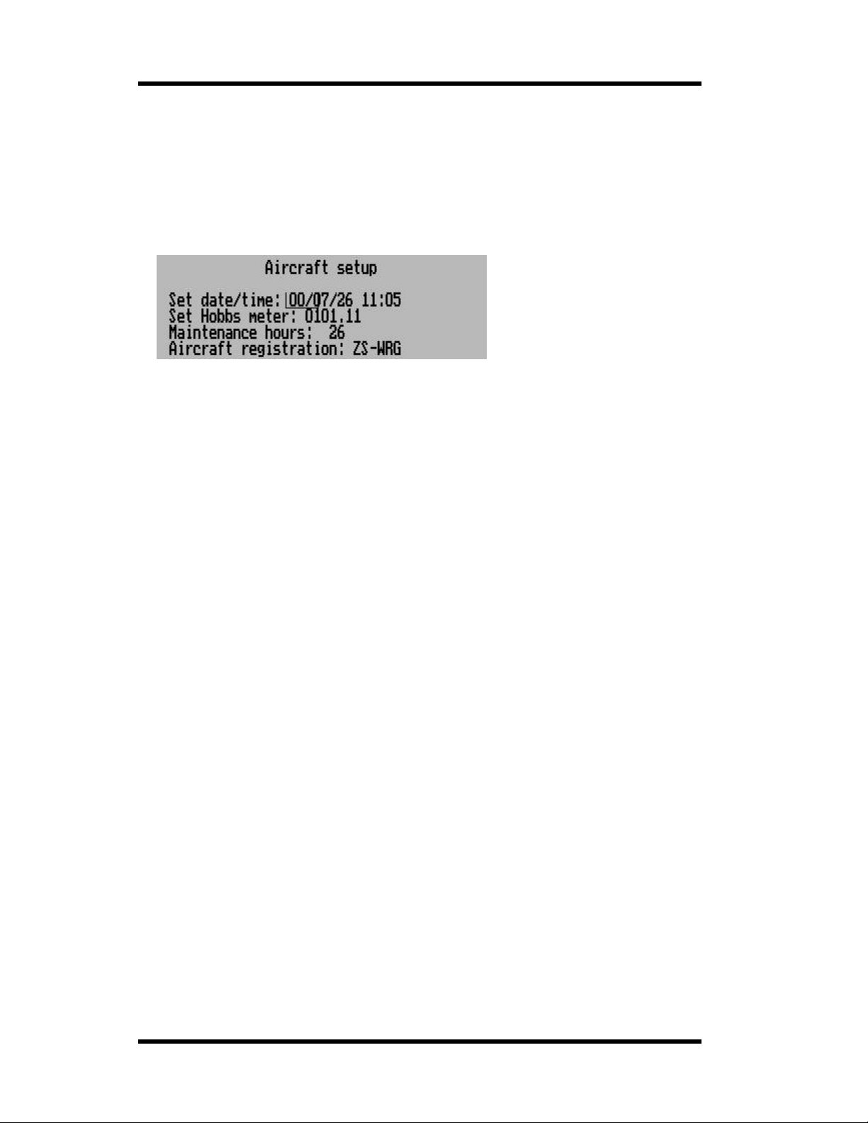
The following items are setup under the Aircraft setup:
a) Date and time for the built in cloc k
b) Hobbs meter pre-set
c) Maintenance meter
a) Aircraft registration number
Date and time
Date and time is used for your flight log. Time of day is a display av ailable both during flight
and on the ground. Please note: The year is never stored in the log. The only reason for
entering the year is to be able t o correct for le ap years. The internal real-time clock contains a
year based counter that can count from 0 to 3 for leap year correct ion.
Use Next/Prev to select the item and then use +/- to change it.
(Nb: The Stratomast e r Ult ra us es a 24- h our cloc k)
Hobbs meter
The hobbs meter contained the the Stratomaster Ultra is pre-settable. You can set the meter
to any time you like, usuall y t his would be to your currentl y known engine time.
Use the Prev/Ne xt keys to select the item and then use +/- to change it.
Maintenance meter
The maintenance meter can be viewed as a hobbs meter “in rever se”. It counts engine
running time down instead of up. This timer is used to control engine maintenance times, for
example spark plug changes or MPI ’s. The maintenance timer is subject to the setting of the
hobbs revs.
Use the Prev/Ne xt keys to select the item and then use +/- to change it.
Aircraft registration
Enter your name or aircraft registration marks into this field to personalize your instrument.
You have 6 characters available.
Use the Prev/Next keys to select a character and then use +/- to change it.
Available charac te r s :
Alphabet in capit al letters
Alphabet in small letters
Numbers 0 - 9
Page 20
Page 21
MGL Avionics Stratomaster Ultra Horizon XL Owner’s manual
Symbols:
! " # $ % & ' ( ) * + , . - . / : ; < = > ? @ [ ¥ ] ^ _ ` { | } ?
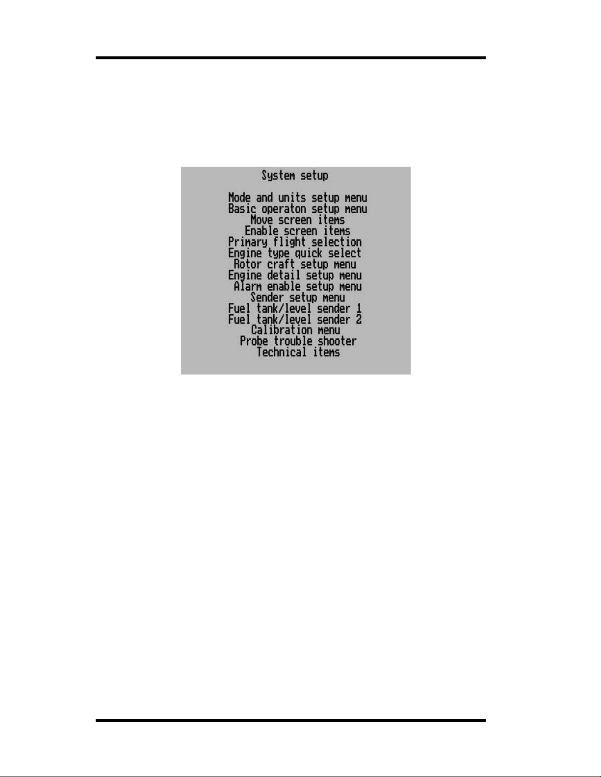
System setup
The system setu p menu is the largest of the menu systems in the Stratomaster Ultra. Here all
functions you re quire to customize and setup your Ultra are combined.
Mode and units setup
Select some oper ating modes and select units of measure.
Basic operation setup menu
Setup basic operat ing parameters, Vspeeds, scales etc
Move screen items
Enter the special display mode t hat allows you to m ove screen items and select display options
for display items supporting more tha n one method of display.
You will move items in the displa y p age that was acti ve when you ent er ed the main menu.
Enable screen ite ms
Here you select which items will appear on which of the two disp lay pages.
Primary fligh t selection
Select a standard VFR or IFR panel and program this into either display page one or two.
Engine type quick select
Select from standard engine types and program a standard layout for your selection. This is used
as a starting point for your engine configuratio n, however, popular engines are directly supported.
Rotor craft setup menu
Here you will find setup items that are relevant for r otor craft such a s h elicopters and gyro planes.
Engine detail setup menu
Engine monitoring details, ranges, alarm levels etc.
Alarm enable setup men u
Enable or disable the various alarm sources in the Ultra.
Page 21
Page 22
MGL Avionics Stratomaster Ultra Horizon XL Owner’s manual
Sender setup menu
Here you can selec t various types of senders for your engine monitoring and customize sender
usage.
Fuel tank/level sender 1
Here you set the fuel tank size for tank 1. You a lso calibrate the fuel level se nder for tank 1 here
(if used).
Fuel tank/level sender 2
Here you set the fuel tank size for tank 2. You a lso calibrate the fuel level se nder for tank 2 here
(if used).
Calibration menu
The calibration menu contain s functions to calibrate variou s sensors such as altimeter etc.
Probe trouble shooter
This function shows you a raw data display from the RDAC engine monitor. This can assist in
finding problems with probes and senders.
Technical items
This function contains items normally only used during manufacture of your Ultra. In production
versions this menu ent r y is hidden. It can be enabled by pressin g both + and – at the same tim e
when you switch on your Ultra.
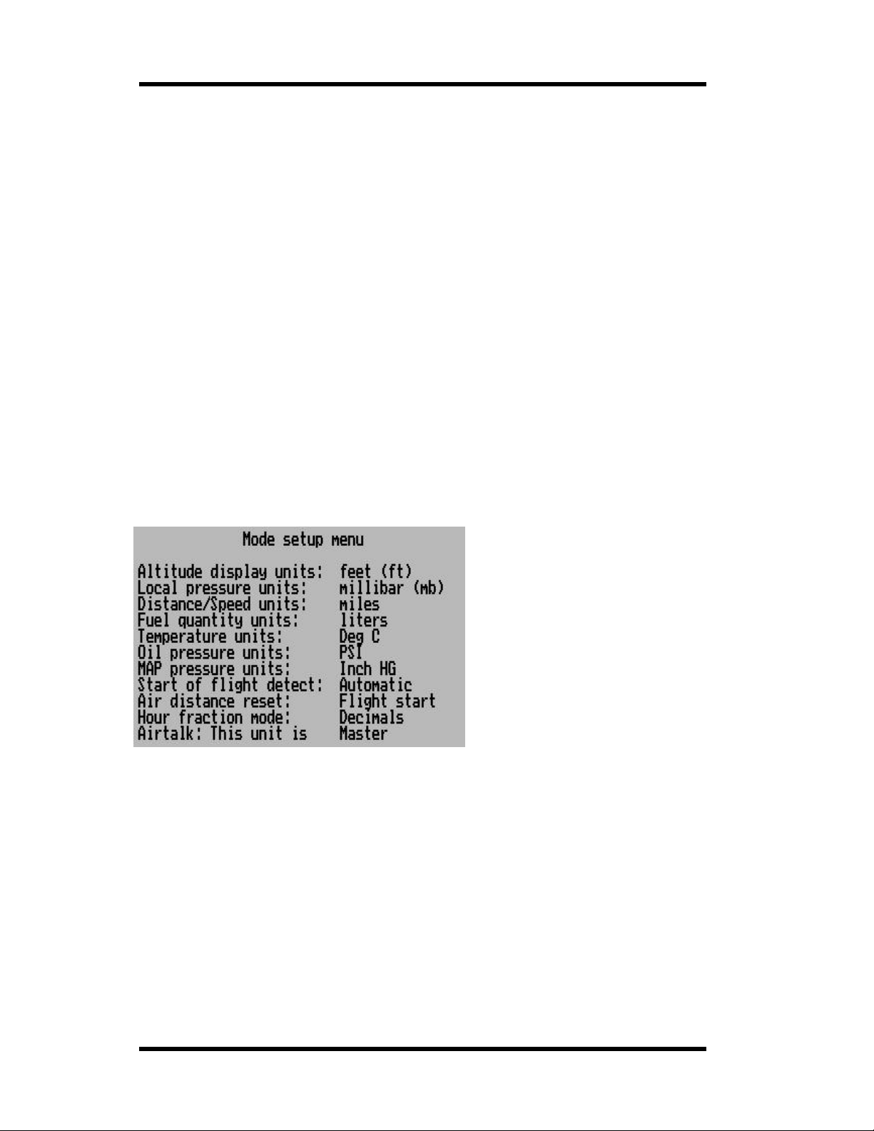
Mode and units setup
Altitude display units
Select whether you woul d lik e to displa y the altitu de in mete r s or feet. T hi s settin g al so
influences th e units used for the VSI. This will be selected to either feet/minute or
meters/second.
Local pressure units
Select your units of local pressure. Options are MilliBar (Hecto-Pascal) or Inches of Mercury.
QNH is the local pressure setting of your airf iel d as giv e n to y ou by your ATC. Be sure to use
the correct QNH to ensure that your altitude is displayed correctly according to local
conditions. This will keep your ATC happy as you will be flying your assigned altitude.
Distance/Speed units
Select how you want to displa y your distanc e. You can choo se betwe en Nauti ca l miles (Nm),
Statute miles (m) and Kilometer s (Km). This setting also influences your airspeed di splay,
resulting in the display of Knots, mph, or kph.
Distances are displayed by the distance traveled indication and range estimate.
Page 22
Page 23
MGL Avionics Stratomaster Ultra Horizon XL Owner’s manual
Fuel quantity units
Select if you want fuel quantity displayed in liters, imperial ga llons, U.S. gallons, Kilograms or
lbs. This setting also influences the fuel flow display.
Temperature units
Select if you would like temperatur e displayed in degrees Fahren heit or Celsius. This setting
influences all te m perature displays such as ambient, water or oil, EGT, CHT etc.
Oil Pressure units
Select if you wou ld like oil pressure displayed in Bar or PSI.
MAP Pressure units
Select if you would like MAP pressure displayed in Bar, PSI or inches of Mercury.
Start of flight detect
Select here if you want the instrument to detect the start of a flight automatically or if you
want to manually start and sto p a flight.
This setting is relevant for the automatic logbook and the flight timer display. If you choose
automatic flight detection, a flight starts if airspeed is above 30 mph (48 Kph or 26 Kn) and
engine revs above the limit set in the tak e- of f revs sett ing (b asic setup men u).
Flights are logg ed au tom atically if a flight dura tion of at least a minute has been detected.
In the manual flight detect mode, you can start and stop flights for logging purpose s yourself
using the main menu. We recommend you use the automatic flight detect mode.
Air distance reset
Select if you would like the air distance trip counter to reset to zer o automatically when you
start a flight. In any case you can reset this trip counter at any time manually from the main
menu.
Hour fraction mode
Select whether you want hour fractions to display in decimal fractions of an hour or in
minutes. This app li es fo r the displ ay of hobbs me te r and fli ght time. Time of day always
displays minutes.
Airtalk This unit is
If you have two Stratomaster units interconnected within your cockpit using the airtalk link,
you must set one unit to be the slave while the other is the master. This is relevant for the
QNH setting. If both instruments power up at th e same time, the QNH from the master is
transferred to the slave.
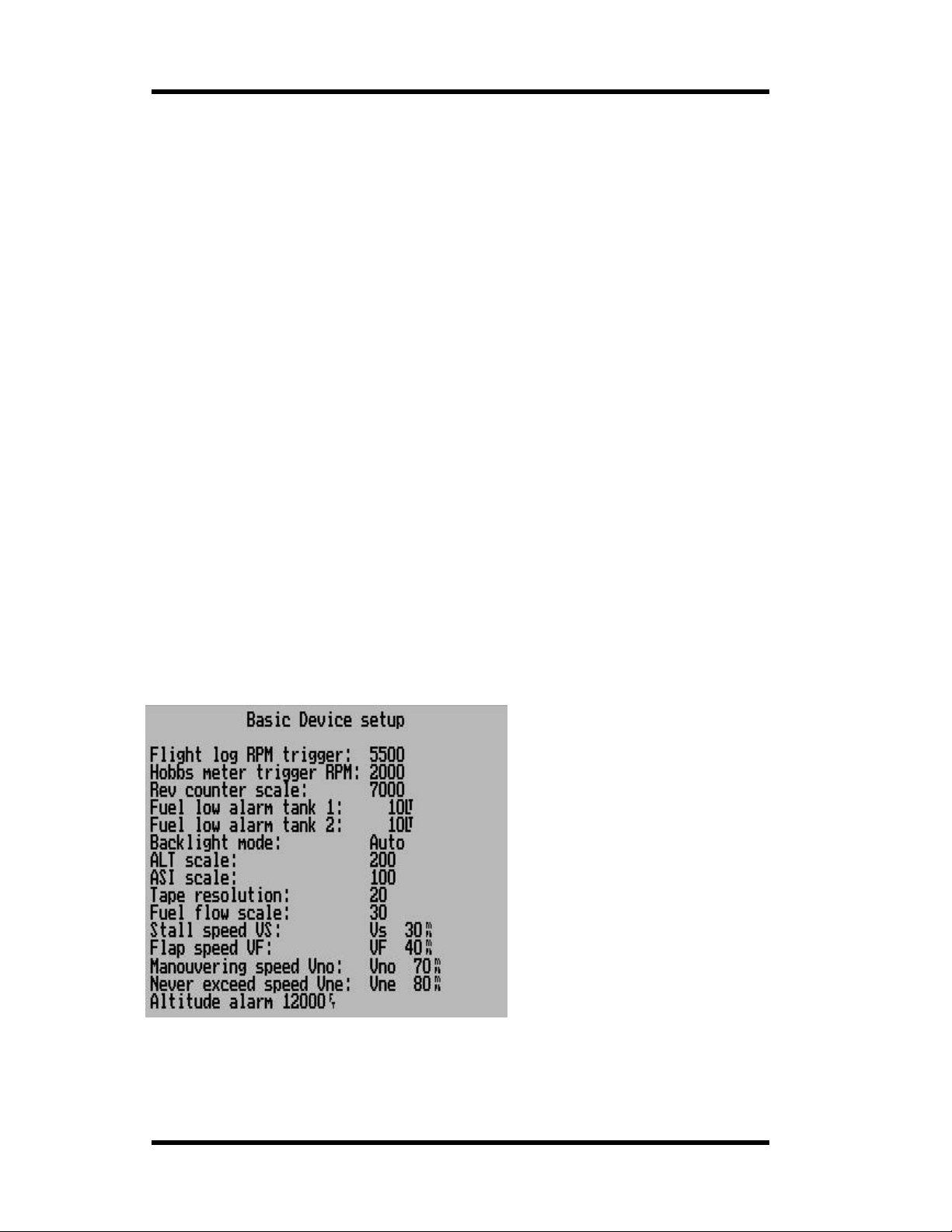
Basic operation setup menu
Page 23
Page 24

MGL Avionics Stratomaster Ultra Horizon XL Owner’s manual
Flight log RPM Trigger (Take-off RPM)
This is the rev limit to use for automatic take-off detection. Take-off detection is relevant for
the automatic logbook. The instrument uses a combination of take-off revs exceeded and
airspeed above 30 mph (48 kph or 26 knots) to de tect the start o f the flight.
Note: Once a flight is started, revs are ignored. Only airspeed is relevant then.
Hobbs meter trigger RPM
This is the rev limit above which engine running time is added to the hobbs meter and
maintenance meter. This setting allows you to choose whether or not to add engine idle
speed time to the hobbs meter. Should you wish to have engine idle count towards the hobbs
meter time, set t he Hobbs revs val ue to less than your normal engine idle speed.
Rev counter scale
Select the maximum RPM for the analog RPM indicator here. You ca n choose from
3000,4000,5000,6000,7000,8000 or 9000 RPM.
For example, a typical Rotax two-stroke would need a setting of 7000 RPM. A Rotax four
stroke would need a setting of 6000 while most other four stroke engines may need a setting
of 4000 or 5000.
Fuel low al arm t ank 1
Fuel low al arm t ank 2
Set the minimum fuel level below which the uni t will generate an alarm.
In order to use the fuel level alar m you must have either a fuel tank level sender installed or
you must use a fuel flow sender (in which case the fuel level can be ca lculated from a starting
value).
Please note that we recommend tha t you calibrate yo ur system in such a wa y that you have
reserve fuel at all times. It is not considered good airmanship to fly your tank empty!
Make allowance that any type of fu el flow or fuel level sensor may malfunction fo r whatever
reason. Should you find unusual, unexpected fuel economy reported by your system, you
most likely are g etting incorrect readings . Al ways backup your fuel manage ment with manual
inspections an d plan your flights using known fuel burn rates of your power p lant.
Back light mode
The back light can be used in one of th ree ways. Permanently on. Permanently off or in
“Auto mode”. In auto mode the back light will switch on if the engine is running or if any key
on the instrument is pressed. The back light will au tomatically swit ch off is there is the engine
is not running or no keys have been pressed for a period of ten minutes.
ALT scale
This setting determines the alt itude steps used wit h the tape based altimeter. Effectively this
sets the resolution of the altimeter tape. This setting is not r elevant for the analog altimete r .
ASI scale
Here you select what scale to use for your analog ASI (airspeed) indicator. You have a
choice of 80, 100, 150, 200, 300 or 400 units of measure. Units of m easure may be miles per
hour, kilometers per hour o r knots.
This setting is relevant for the a nalog ASI only.
Tape resolution
This setting dete rmin es the AS I ta pe resol u ti on if a tape based ASI is used.
Fuel flow scale
Here you select what scale to u s e for your fuel flow indicator.
Stall speed Vs
The Stall speed or mi nimum speed setting for the VSpeed display. Also sets the limit for the
low speed alarm.
Flap speed Vf
The maximum speed you may operate with flaps. Used for the spe ed arc.
Maneuvering speed Vno
Your maximum free maneuvering speed, often your maximum cruise speed. Used for the
speed arc.
Never exceed speed Vne
Your maximum allowable s peed. Used as limit for the hig h speed alarm. Also used for the
VSpeed display.
Altitude alarm
Your altitude ceiling above which an alarm will be issued. Note t hat the alarm must be
enabled separately.
Page 24
Page 25
MGL Avionics Stratomaster Ultra Horizon XL Owner’s manual
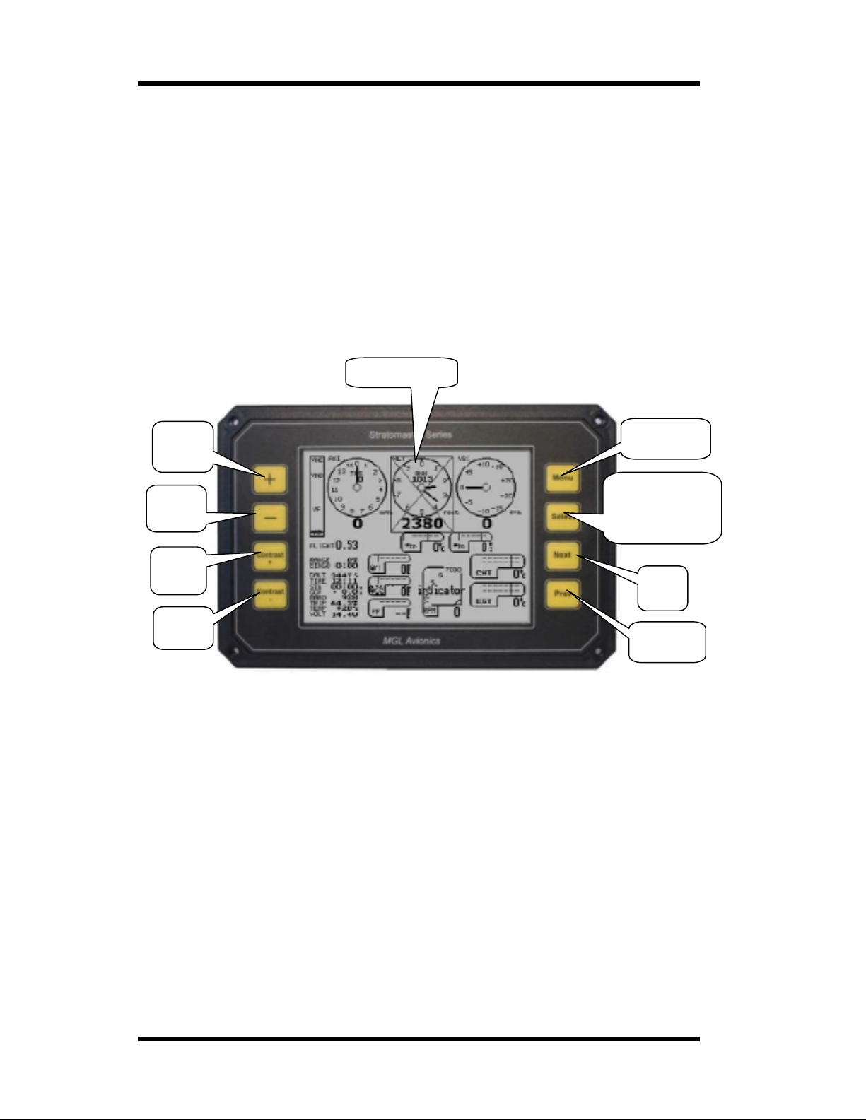
Move display items
This functions enters a special mode allowing you to move screen display items. Select the
display page that you want to modify before entering this function .
During the move function, the normal display will be shown with the currently selected item
indicated by a frame and a cross as shown in the image below.
If you want to a dd a new item, enable it onto the screen first using the “Enable screen items”
function, then enter the “Move display items”.
Select the item to move using the “Prev” and “Next” buttons.
“+” moves th e item right by 8 pixels.
“-“ moves the item left by 8 pixels.
“Contrast –“ moves the item up by 1 pixel.
“Contrast +” moves the item up by 1 pixel.
“Select” cycles through display options for the selected item.
“Menu” ends the move mode and resumes normal operation.
Selected item
Move
right
Move
left
Move
up
Move
down
End move
mode
Cycle through
display options
for selected
item
Next
item
Previous
item
You can also use the Windows based Ultra Horizon XL panel design pr ogr am to design your
panels and download them to your Ultra using a PC to airtalk cable.
This program is a free download from the MGL Avionics website. Airtalk cables are a low cost
option for your Ultra and are available with RS23 2 or USB interface.
Move mode should never be used in flight !
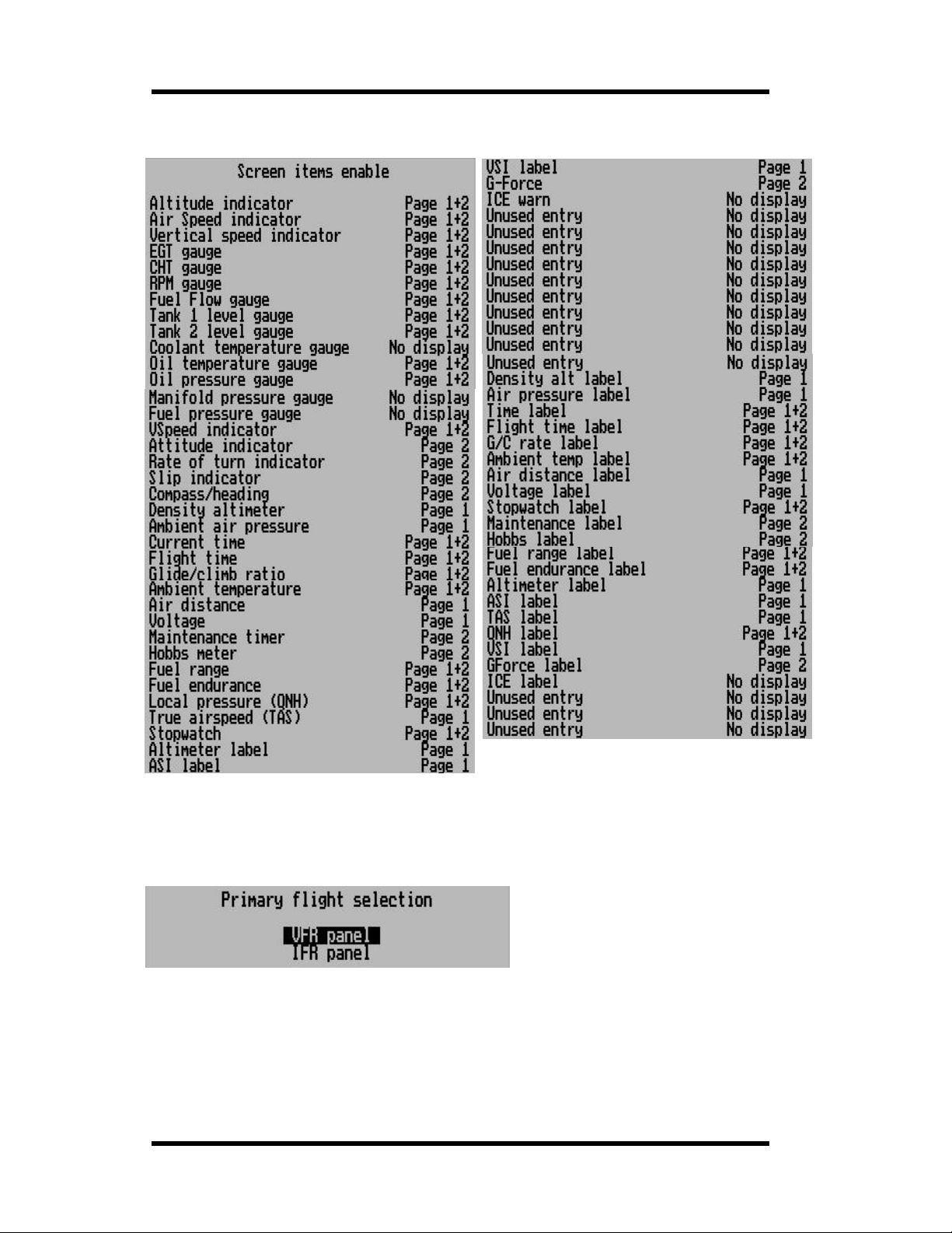
Enable screen items
This menu allows you to enable ev ery individual screen display item onto one or both of the
available dis play pages.
You would normally use this function to either remove or add an it em, then you would use the
“Move display items” function to move items to rearrange the display to suit your needs.
The following displays show the complete list of items using the def ault setup. Ther e are a few
entries mark ed “ Unused entry”. These are reserved for future expansion and have no current
Page 25
Page 26
MGL Avionics Stratomaster Ultra Horizon XL Owner’s manual
function. Your list may vary slightly from the l ist presented h ere as we may add additional disp lay
items in future versions.
To change any item, move the highlight to the item using the “Next” and “Prev” buttons, then use
“Select” to cycle through the options.
Primary flight selection
This function is included to allow you to reset your panel to the factory default. These two options
will create either a VF R or IFR panel but t hey will not change any of your engine setup or engine
display items placement on the scr een.
Once you have selected VFR or IFR panel, you will be asked on which display page you would
like to place the panel.
The factory de fault places t he VFR panel on page 1 and the IFR panel on page 2.
Should you never require IFR, you can use this funct ion to place a VFR panel on page 2 as well.
Page 26
Page 27
MGL Avionics Stratomaster Ultra Horizon XL Owner’s manual
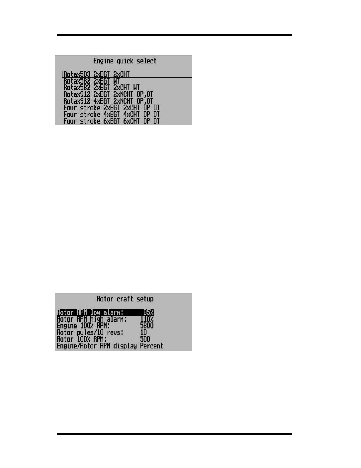
Engine type quick select
This function a llows you to setup a basic engine monitoring system mo st suitable for your engine.
Once you have made your selection, go into the engine detail set up menu to change any settings
as required for your engine.
These functions assume th at you are using def ault primary flight instrum ent s in their stand ard
locations (primary flight in struments at the top half of the display).
You will be asked if you would lik e to program your selection on page 1 or page 2. The engi ne
layouts are slightly different for the two pages. The layout for page 2 is more compact as it is
intended for the IFR screen which needs more space for the primary flight instruments.
It is advisable to program your engine choice into both pages one or two or else you could
end up with a different engine type monitoring in each page.
The selected eng ine type is intended as a starting point from w here you can customize the
settings to suit your engine and screen layout best.
Rotor craft setup menu
Should you want to use the Ultra with a helicopter or autogyro aircraft, simply change the rev
counter (RPM display) to rotor craft mode. You do this in the “Move screen items” function: Select
the rev counter and use “Select” to cycle through the display opt ions until you have the opposing
needle rotor and engine RPM display.
This setup menu allows you to cust omize your display according to your aircraft s needs.
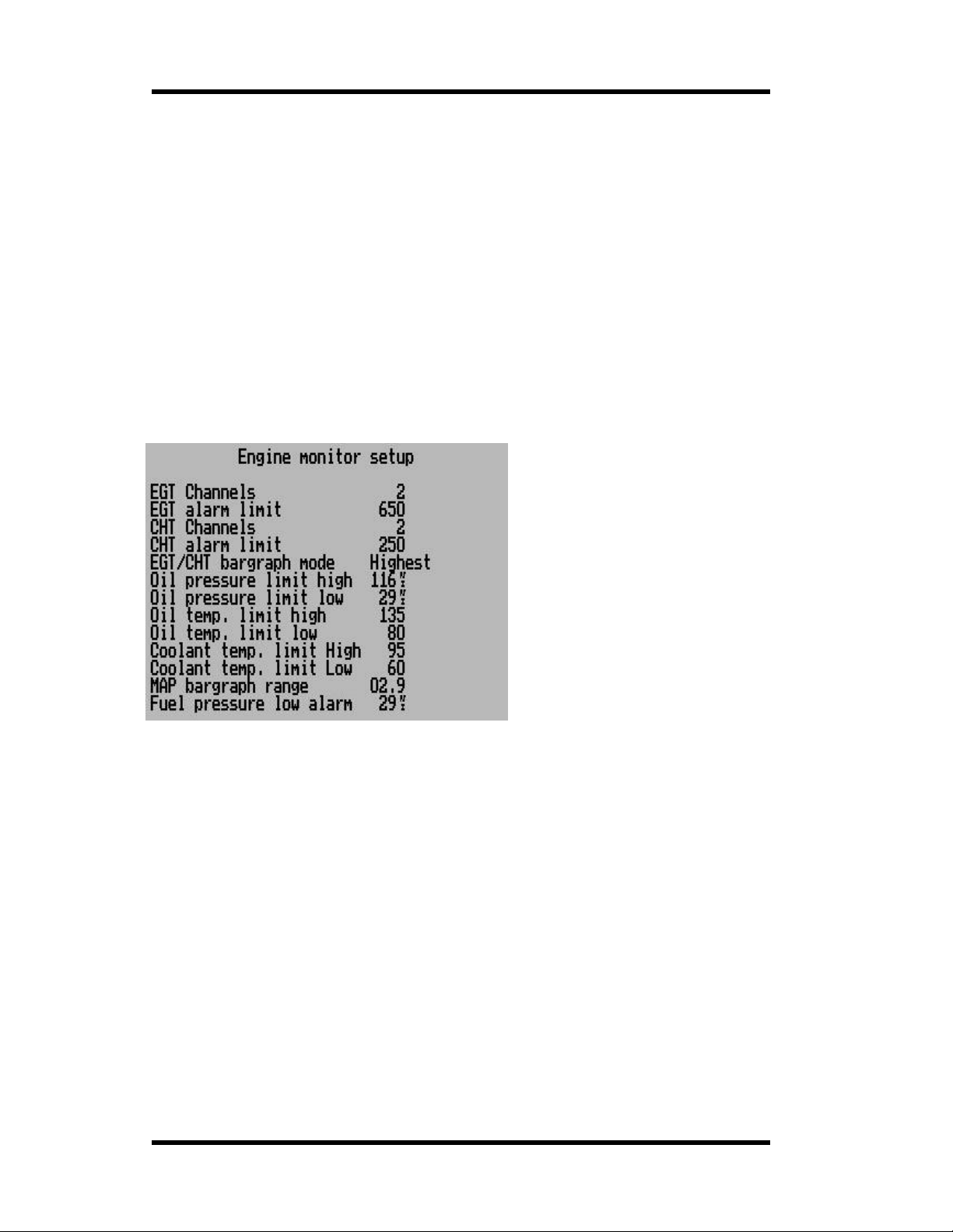
Rotor RPM low alarm:
Choose your low RPM limit for your r otor speed. This is entered as a percentage of your nominal
100% RPM (set below). Note: you still need to enable this alarm if you want to use it.
Rotor RPM high alarm:
Choose your maxim um permissible rotor RPM as a perce ntage relative t o your 100% setting.
Please note that you still have to enable this alarm if you want to use it.
Engine 100% RPM:
Enter the RPM value that corresponds to a 100% power setting. This is used to calculate the
correct 100% needle position for your engine RPM display.
Page 27
Page 28
MGL Avionics Stratomaster Ultra Horizon XL Owner’s manual
Rotor pulses/10 revs:
Enter the number of pulses your rotor speed pickup sensor will creat e for 10 full revolutions. If
your setup will create a single pulse per revolution, enter the value 10. Gyro aircraft will often use
a geartooth senso r on the prerotati on gear. In this ca se it is common to ente r values of 10 times
the number of gear teeth on th e gear . A typical value would be around 400.
Rotor 100% RPM:
Enter the RPM value that corr esponds to a 100% r otor speed (sett ing entered below). This is
used to calculate the correct 100% needle position for your rotor RPM display.
Engine/Rotor RPM display…
Select if you would like the numeric readout of your rotor/engi ne RPM display to read in percent
or in actual RPM.
We recommend that you cho ose RPM unt il yo u hav e your syste m setu p cor rectly.
It is common for Gyro planes to use RPM as readout while helicopters tend to use percent.
Engine detail setup menu
The engine detail setup menu allows you to cust omize your engine monitoring parameters. These
parameters will be set to factory defaults for the engine type you have selected if you have used
the “Engine type quick select”.
EGT Channels…
Enter the number of EGT channel s you would like t o mo nitor. You can select up to 12 chan nels
but the total num ber of EGT and CHT channels combined may not exceed 12.
The EGT display will change size as you add or remove channels. Should you require a large
number of channels but do not have sufficient display size, you can choose a more compact
scanning display using the “ M ove screen items” menu.
EGT channels start at RDAC input channel TC1.
EGT alarm limit…
Set the alarm limit (re d line ) as required for your engine. Most two st roke engine use a limit of 650
degrees Celsiu s. Many four strokes use 850 degrees Celsius. This value also sets the bargraph
display range. Please note that the EGT bargraph starts displaying when a temperature of 50% of
your alarm limit is reached. This ensures a good reso lution of the bargraph in the temperature
region that you would be inter este d in.
Verify the required EGT alarm limit for your eng ine by consulting the engine manufacturer or th e
documentation that came with your engine. Exceeding the recommended EGT temperat ure may
seriously dam ag e your engine.
CHT Channels…
Enter the number of CHT channels you would like to monitor. You ca n select up to 12 channels
but the total num ber of EGT and CHT channels combined may not exceed 12.
Page 28
Page 29

MGL Avionics Stratomaster Ultra Horizon XL Owner’s manual
The CHT display will change size as you add or remove channels. Should you require a large
number of channels but do not have sufficient display size, you can choose a more compact
scanning display using the “ M ove screen items” menu.
Rotax 912 and Rotax 914 engines have two built in CHT senders that are not thermocouples and
they cannot be used with the normal CHT channels. Thes e senders are ordinary NTC type oil
temperature senders.
You can use these senders with the Ultra by selecting “Rotax 912” in the CHT channels setup
(select the number of channels past 12). When you have done this, you can connect the two
Rotax CHT senders to the RDAC inputs CHT1 and CHT2 . I n the “Sender set up” menu, ensur e
that the Rotax 912 CHT probe type is selected to “Standard NTC”.
Verify the required CHT alar m limit for your engine by consult ing the engine manufacturer or the
documentation th at came with your engine. Exceeding t he recommended CHT temperature m ay
seriously dam ag e your engine.
CHT alarm limit…
Set the alarm limit (red line) as required for your engine. Many air cooled engines use a limit of
250 degrees Celsius whi le liqu id coo le d eng ine s hav e limit s arou nd 135 deg re es Cel ciu s. Man y
air cooled four stroke engines have o il cooled heads wit h a CHT limit of around 135 degrees a s
well.
This value also sets the bargraph display range. Please note that the CHT bargraph starts
displaying wh en a temperature of 50% of your alarm limit is reached. This ensure s a good
resolution of the bargraph in the temperature region that you would be interested in.
EGT/CHT bargraph mode
Select if you want the digital readout to show the highest temperature at all times or if you want
the digital reading to scan though the chann els.
Please note: This setting only affects the normal, large EGT or CHT display. Should you select
the compact di splay, scanning is enabled automatically.
Oil Pressure limits
Enter the oil pressure limits as yo u r equire them. Note that you can enter both a low and a high
limit and you can individually enable or disable these limits for alarm purposes in the “Alarm
enable setup menu”.
Most applications only monitor low pressure (oil pump failure or oil leak). You can also monitor for
high pressure if you like. High oil pressure may indicate blocked oil passages or a blocked oil
filter (depending where you measure the pressure).
Oil and Coolant temperature limi ts
Choose your coo ling system temperature alarm limits. Note that yo u can also choose a “l ow
temperature limit”. Man y water cooled engines require a minimum coo l ant temperatur e and this
function allows you to have an alarm if the tem per ature drops below your requir ed limit.
If you do not know what this limit is, select about 60 degrees C – this would be sufficient for most
engines. High limits range from about 80 degrees C to about 95 degrees C. Consult your engine
manufacturer’s sp ecifications.
Oil temperature high limits ar e usually in the region of 135 degrees Celcius.
You can individually enable or disable each of these alarms in the “Alarm enable setup menu”.
MAP bargraph range
This setting determines the display range window f or the manifold pre ssur e indicator bargraph.
For eample, if you select a value of 100 millibars, t he bargraph wi ll indicate +/-10 0 m illibars from
the standard s ea level pressure (1013.25 millibars).
Your selection would depend on the manifold pressure range that your engine produces and this
also differs if you have a turbo charged engine or not.
Fuel pressure low alarm
Select the minimum pressure required for your fuel pressure below which an alarm will be
activated. You still need to enab le the alarm separ ately.
Page 29
Page 30
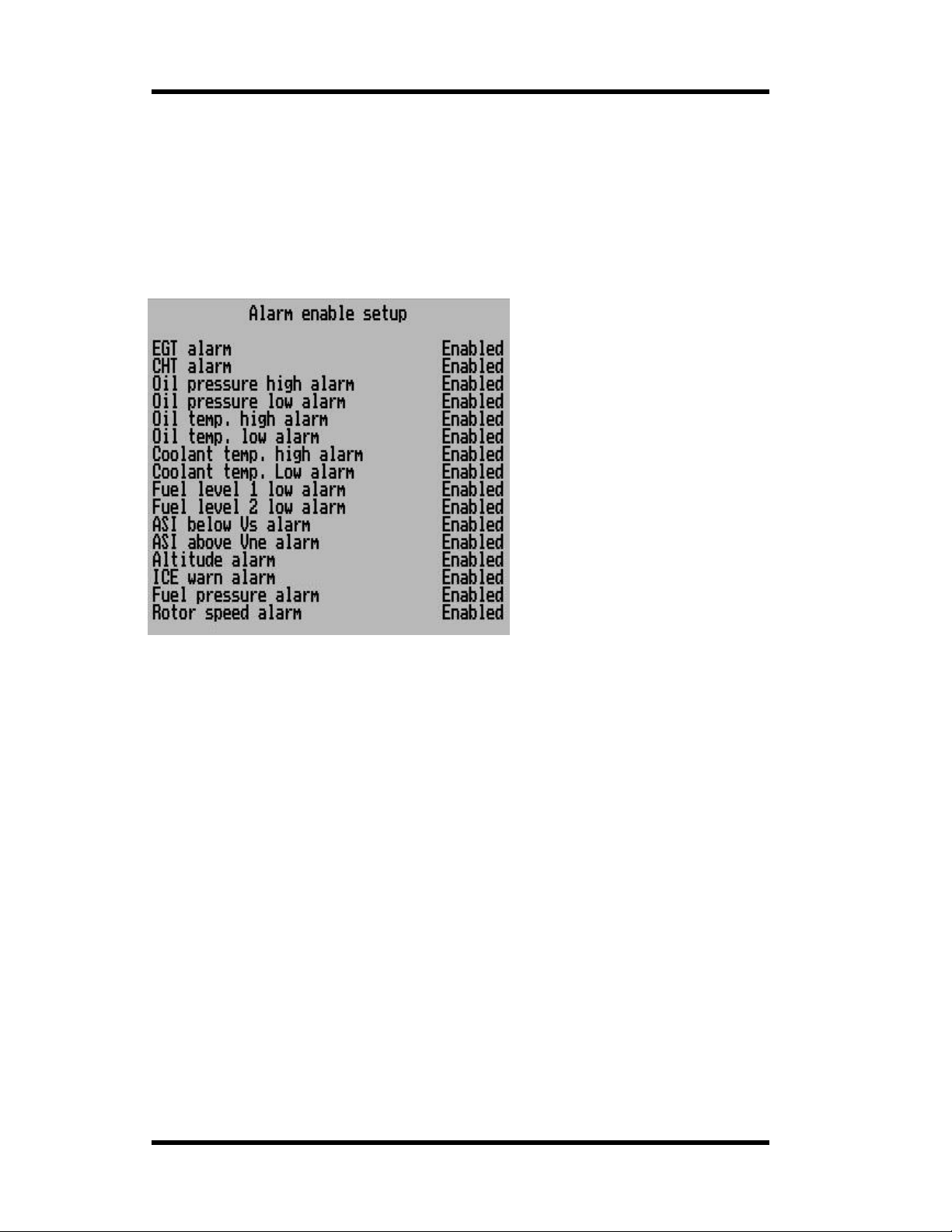
MGL Avionics Stratomaster Ultra Horizon XL Owner’s manual
Alarm enable setup menu
This menu controls the ind i vidua l alarm s in the Ultr a Hor izon XL s ystem You can enab le or
disable each alarm source as you require for your application.
A disabled alarm w ill never activate, r egardless of condition.
Please note that the ICE warning alarm requires installation of a suitable temperature probe in
your carburetor or airbox intake. This function is not normally used with fuel inject ed engines but
it may be used if the construction of air intake passages can promote ice build-up.
Page 30
Page 31
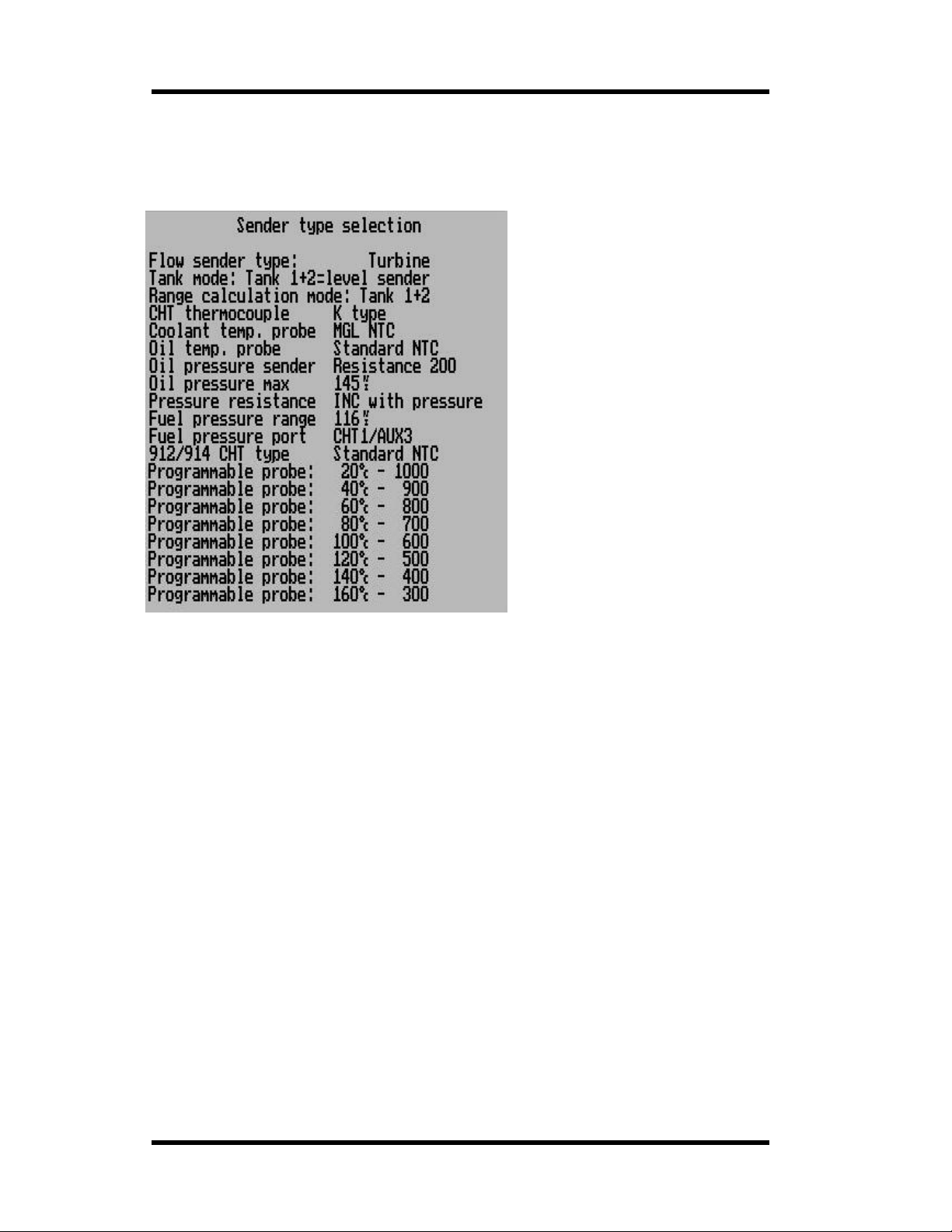
MGL Avionics Stratomaster Ultra Horizon XL Owner’s manual
Sender setup me nu
The sender setup selection menu is us ed to select the type of senders you have connected.
Flow sende r type
Select if you have a turbine type flow sender connected or are using the fuel injection s ystem
monitor to obtain fuel flow information. The possible selections are:
Turbine: Impeller or tu rbine type with pulsed output si gna l.
Injector H: High side injector.
Injector L: Low side injector.
H and L refers to the type of signa l used to switch the injector. Sh ould you select the
incorrect setting, fuel flow will decrease with engine power increasing. In this case simply
select the other setting.
Please note that you should select the K-factor suitable for your flow sender or injector. This
is done in the cal ibration menu. The correct K-factor is norma lly published for your flow
sender. For fuel injection systems, the correct factor is found by exp erimentation.
Tank mode:…
Here you select how you would lik e to use your two tank level displays .
Options are:
a) Tank 1 and Tank 2 are each connected to a physical fuel tank level sender
b) Tank 1 is connected to a physical level sender and tank 2 uses a calculated fuel level
c) Tank 2 is connected to a physical level sender and ta nk 1 uses a calculated f uel level
Calculated fu el levels require that a fuel flow sender is installed.
Range calculation mode…
Select which tanks to take into account for your f uel range and endurance calculations.
Options are:
a) Tank 1
b) Tank 2
Page 31
Page 32

MGL Avionics Stratomaster Ultra Horizon XL Owner’s manual
c) Tank 1+2
Range and endurance calculation requires a fuel flow sender.
CHT Thermocouple
CHT senders supplied by MGL Avionics are K-types. Some CHT senders from other
manufacturers ar e J-types.
The characteristics of J and K types are different so it is important that you select the correct
thermocouple type.
EGT thermocouples are K-type s. It is very rare that other types are used here.
Coolant temperature probe
This entry selects which probe you have connected as water temperature prob e.
You can select the M type probe (MGL supplied NTC probe) or the MGL precision
temperature probe (see below).
You can also select Westach NTC water or oil temperature probe s a nd the programmable
probe.
Oil Temperature probe
This entry selects which probe you have connected as oil temper ature probe.
You can select the Standard type probe or the MGL precision temperature probe (see
below).
The Standard type oil temperature sender is a type used in many engines and most oil
temperature pr ob es wi ll wo rk with this sett ing. The oil temperatu re pro be in a Rota x 912 is of
this type.
You can also select Westach NTC water or oil temperature probes and the programmable
probe.
Oil pressure sender
Oil pressure resistance refers to the resis t ance the oil pressure sende r will ex hi bi t at its
maximum pressure. 200 ohms is the reading for the oil pressure sender fitted as standard to
Rotax 912 and 914 engines at a pres su re of 10 bar. You can adjust the setting over a wide
range to allow use of the instrument with a large variety of oil pressure senders. Oil
pressure senders sup por ted must increa se res ist an ce fair l y linearly with pressure. Thi s is the
case with most standard automotive senders.
Most available automotive senders will be in t he range of 100 to 400 ohms. We recommend
the oil pressure senders available from VDO.
Most oil pressur e s enders increase the ir r esistance with pressure. There are a f ew types that
work in reverse to t his. These senders can also be use d.
Oil pressure max
This setting is the pressure at maximum resistance (or minimum resi stance if a reversed
type of pressure sender is used).
For example, the oil pressur e se nder fitted to Rotax 912 engines is a 10 bar type. Some
other senders are 5 bar types.
Pressure resist ance…
Select if your oil pressure senders resistance increases or decreases with pressure. Most
senders increase resistance with pressure.
Fuel pressure range
Select the pressure for your fuel pressure sender to deliver an output voltage of 5V.
The Ultra supports fuel pre ssure senders tha t can deliver a DC output voltage f r om 0V to 5V,
linear with applied pressure.
Fuel pressure port
Select where you have connected the fuel pressure sender on the RDAC. Optio ns are
CHT1/AUX3 or Fuel level in pu t 2.
Page 32
Page 33

MGL Avionics Stratomaster Ultra Horizon XL Owner’s manual
912/914 CHT type
Select the built in CHT probe type used for 912/914 engines. This should be set to “Standard
NTC” unless you are specifically using a different type of probe.
The programmable tem peratur e probe
You can select a user programmable probe for either coolant temperature, oil temperature or
Rotax 912 probes. Of course, if you would like to use the same type of probe for some or all
of these then you can use the programmab le probe for all of them.
In order to use the programma bl e probe, you need to tell the instrume nt ho w the pro b e
behaves with temperature.
Luckily, this is quite easy to do.
You will need an accurate reference thermometer that is able to work over the desired
range. If you do not have such a t her m ometer, simply use one of our K-type EGT or CHT
senders together with your Ultra !
We recommend you use cooking oil in a pan. Immerse both the reference thermometer and
the probe you want to use into the oil. Connect the probe to the oil temperature channel
input of the RDAC.
Use the Ultra s b uilt in probe trouble shooter t o get a reading from the probe.
Slowly heat the oil and monitor the oil temperature. Whenever the oil tempera ture reaches
any of the temperature marks, take a note of the probe reading in the probe trouble shooter.
Don’t worry if you do not get qu ite to 160 degrees, estimate thi s one if necessary.
Once you have obtained all the readings, enter these into th e above form in th e sender
setup menu. Now you are ready to use the pr ogrammable probe with your Ultr a.
Please note that this is designed for NTC probes which have a falling resistance with
temperature. Other probes cannot be used. NTC probes are the mos t common types.
The MGL precision temperature probe
MGL Avionics manufactures a precision temper ature probe based on an accurate and well
proven semiconductor chip. This sender is more expensive compared to the ordinary
automotive senders used in sta ndard applications but offers outstanding accuracy and as
additional advantage is completely electrically isolated from the engine it is fitted to. This is
an advantage in some installations as the te mp er ature readin g is not influenced by electrical
currents flowi ng in the engine. This sender ca n be us ed to me asure temperatures from zero
degrees Celsiu s to about 180 degrees Celcius. The sender is suitable for water or oil
temperature measurement s to an accuracy of + /-2 degrees over the full temperature range.
Page 33
Page 34
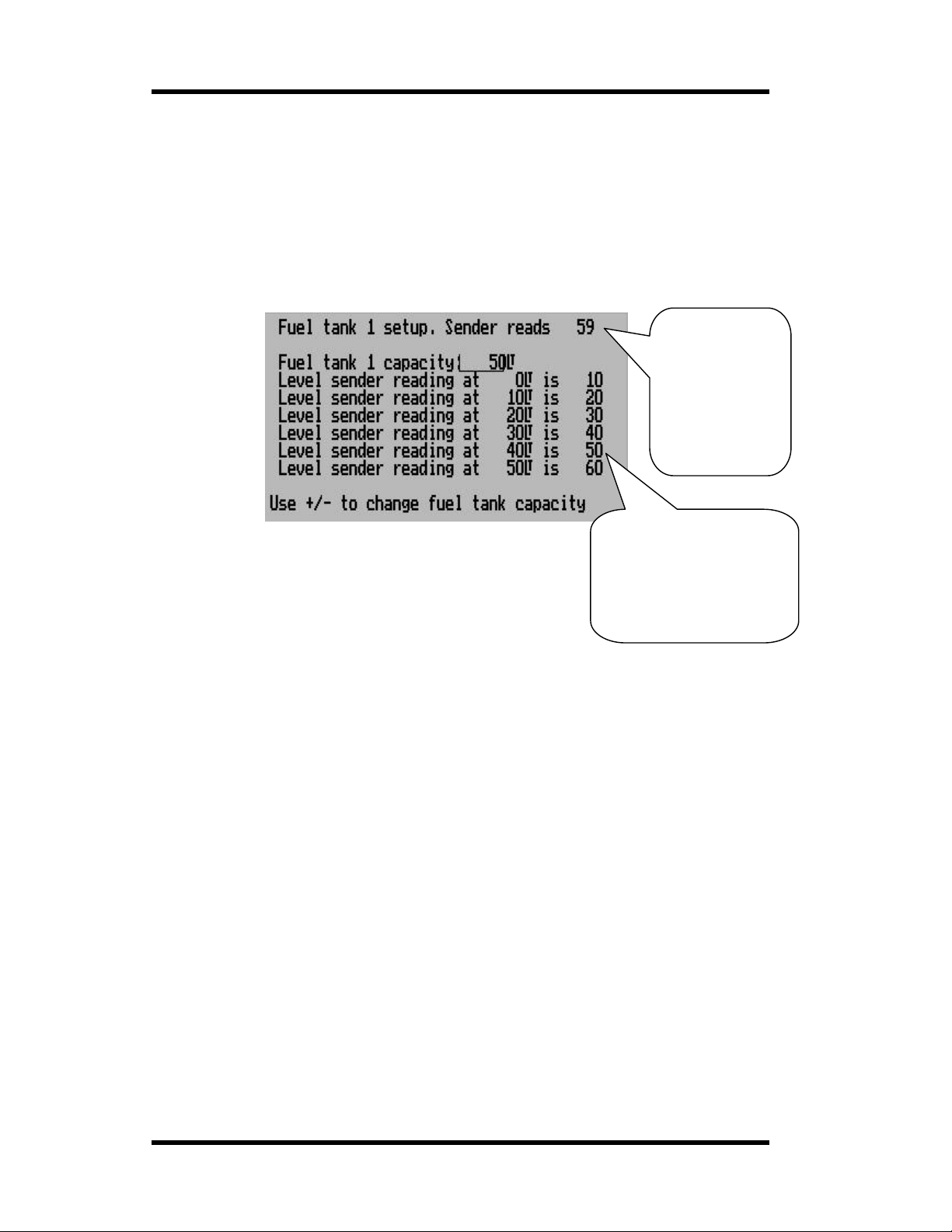
MGL Avionics Stratomaster Ultra Horizon XL Owner’s manual
Fuel tank/level sender setup 1 and 2
This function is used to setup and calibrate yo u fuel level sender(s). You would use this
function partial l y even if you do not have a fu el level sender in stall ed but are usin g a fuel flow
sender. In this case the instrument can provide you with a tank level display as well as it will
calculate the remaining fuel by subtracting fuel used (after you have given it a starting value).
In this case all you have to do in this menu is to enter the capacity of your fuel tank so that
the fuel level bargraph can show the correct level. You should also note that it is not possible
to enter a fuel level greater than the tank capacity even if you only use the fuel flow sender
and not a tank level sender.
This number is
the value read
from your fuel
level sender.
The actual value
is not important,
as long as it
changes with
fuel level.
Regardless of yo ur use of a fuel flow sender, you can install a
fuel level sender into your fuel tank. These level senders are
inexpensive and are available as after market replacement
fittings from a car spares outlet. We recommend the senders
available from VDO. Be aware that some makes of cheap
level senders can prove troublesome, as the lever arms tend
to be stick y. Th is prevents the floats from floating on th e s urface of the fuel at all times. As a
consequence, this will lead to incorrect fuel level indication.
Once you have installed a fuel level sender into your tank, make sure the float can travel all
the way from em pty to full pos ition without hindrance of any kind.
The calibration procedure should be carried out with your air c raft in flight att i tude. This means
you need to lift t he tail if you have a tail-dragger or lift the nose wheel if you have a
weightshift trike. You start the calibration pro c edure with an empty tank.
Your first dete rmi nation should be how muc h reserve fuel you shoul d car ry . Res er ve fuel
would be fuel that is not taken into account by the fuel level sender. We recommend at least
10% of your fuel tank capacity as reserve fuel, preferably even more.
To illustrate the calibration procedure, let us assume we have a weightshift trike with a tank
capacity of 50 liters without reserve.
We decide to use a five-liter r ese r ve, leaving us with a usable fue l capacity of 45 liters.
Our first step is now to enter this capacity into the instrument. Us e the “prev” and “next” keys
to move the highlight to the “fuel tank capacity” item. Then use the + and – keys to set the
entry to read 45 liters.
Our next step would be to raise the nose gear of the trike to flight position. An upturned
bucket or similar item is normal l y all that is requ ired .
We now start with the empty tank. Add five liters of fuel (our reserve quantity) using a suitable
measure. Make sure the measure is suitably accurate.
These are the level
sender readings at the
various fuel levels. Use
the “select” k ey to transfer
the current reading to the
relevant fuel le ve l slot.
Page 34
Page 35

MGL Avionics Stratomaster Ultra Horizon XL Owner’s manual
This is now the “l evel sender reading at 0 Lt” position. Move the h i ghlight to thi s p osition and
wait until the sender reading has stabilized (You will see the sender reading at the top line).
This could take up to a minute so have patience.
Should this number not react to changes of your level sender position, then you have a
problem. Please check your wiring accor di ng to the ins talla t ion sect ion of this manu al.
If you see the nu mber changing th en everything is well. Once it has stabilized and the
highlight is on th e 0 Lt position, press the “select” key to transfer the reading from the sender
to the calibration point.
Now you are ready for the next step. Add the required amount of fuel to get to the next level
(In our case 9 Lt – this is 20% tank capacity). Once done, wait for the reading to stabilize and
press “select” again after you have moved the h i ghlight to the “9 Lt” position.
Proceed in a similar manner until you have reached the last calibration position at 100% tank
capacity.
You are done !
Press “Menu” to exit this function. This will write the new calibration to permanent memory in
the instrument. You can repeat this calibratio n m any times so do not worry if you do not get it
right the first tim e.
The instrumen t uses the 6 calibr ation points to w ork out a correc tion curve that takes into
account the tole rances of your fuel level sende r and t he sh ape of your fuel tank. This resu lts
in an incredibly accurate and usable fuel level display that far exceeds that available from
ordinary dial type gauges.
Note:
The calibration pos iti on s ma y be edite d by usin g the + and – ke ys. This all ow s you , in theor y,
to copy calibration settings from one instrument to another. We however recomme nd that you
do go though th e calibration pro c edure even if the two aircraft are identical in all respects.
Tolerances do e x ist and the calibr ation cancels the s e out.
Accurate fuel level displays are a vital safety factor for an aircraft and a very useful feature for
peace of mind during cross county flig hts.
Notes on Slope error
Sender value is a value determin ed b y the Strat om ast er Ultra. It is used to calcula te e.g. fue l
level, fuel bingo estimate and current range estimate. The fuel tank setup sender value can
either increase in value as fuel is added on decrease in value if fuel is added. This is
dependant on the type of fuel level sender used. However should the second reading be
larger than the first reading all readings wi ll have to be larger than the previous reading.
Likewise should the second reading be smaller than the f irst reading all readings will have to
be smaller than th e previous reading . I f this is not the ca se the wording "Slope error" will be
displayed. This could happen when fuel was removed instead of added betwee n s teps, no
fuel was added be tween steps or when t he fuel level sender was moved in the wrong
direction e.g. moving the fue l level sender manually when it is not inserted in to th e fuel tank.
Should you get a slope error mes sage determine the cause of the error. If you do not know
the cause of your error it is best to start from scratch. It should be remembered that accuracy
is the fuel tank calibration is very important to enable your Stratomaster Ultra to display the
correct data.
Page 35
Page 36
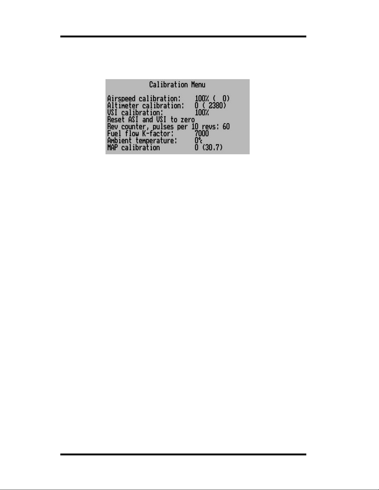
MGL Avionics Stratomaster Ultra Horizon XL Owner’s manual
Calibration Menu
The calibration menu contains functions to calibrate important sensors.
Airspeed calibration
This function is used to calibrate the airspeed reading. It works in % relative to a nominal
value. Your calibration certificate will give you the setting required for correct reading if no
external airflow factors are present. In many aircraft installations it may be required to correct
the reading t o cater for errors created by the airflow around your airc raft.
You can use the + and – keys to change the calibration factor.
Altimeter calibration
This calibration is done at the factory using very accurate references. It is not normally
required to change this sett ing. You may do so if you feel that you would rather use anoth er
reference, like your local airfield’s elevation accord ing to survey maps.
Be aware that gen erally survey maps and GPS read ings may not give you the expect ed
readings and are subject to small errors. For example, your GPS receiver may be using a
different datum of reference to the survey maps.
The value entered here is a corr ection factor that is entered during calibration of your
instrument. Thi s fact or is show n on your calibrat i on cert ifi cat e.
At sea-level, one unit corresponds to an air pressure difference as expected for a 7 ft (2,1 m)
change in altitude. At 5 000 ft (1 524 m) MSL this corresponds to about 10 ft (3 m). A
positive correction factor will de crease the altimeter reading and a ne gative factor will
increase the reading.
Please do not confuse this setting with the QNH (local pressure) setting available from the
main display (+ and – keys).
VSI calibrati on
This is a technical function that is used to calibrate your VSI to read exact rates of climb or
decent. This f unction works as a percenta ge of initial reading. The default s etting for this
function is 100%. Increa sin g this value increases the VSI readi ng and decr ea sing the valu e
decreases the reading.
Suggested calibration method .
After you have installed the instrument, perform a calibration flight. This should be done in
very calm conditions. Turbulence and thermal activity will make accurate calibrat ion
impossible. Many areas have ideal conditions during early mornings or late afternoons.
Place the instrument in “feet” units mode for ease of calibration.
Take your aircraft to a few thousand fe et above ground and start a glide with a low power
setting. Take a stopwatch and when the glide is stable (stable VSI reading) start the
stopwatch. Take note of yo ur altimeter rea ding at the same time.
Page 36
Page 37

MGL Avionics Stratomaster Ultra Horizon XL Owner’s manual
Continue the s table glide for one minute exactly. After the m inute has fini shed, take another
reading of your alt ime te r.
Example:
VSI reading during stable glide: -400 ft/min
Start altitud e: 250 0 ft.
End altitude: 2050 ft.
In the above example the VSI is under reading by about 12%. Se t your VSI calibr ation to
112% to cancel out the error.
Reset ASI and VSI to zero
This function is us ed to calibra te the zero point r eadings of airspeed and vertical speed
indicators (ASI and VSI). Use this function from time to time to zero the readings. This way
your instrument will always perform at its best. Per form the zero ca libration when your
aircraft is on the ground and not exposed to any airflow (for example when it is parked
inside the hangar). (The engine should not be running).
Do take care to perform the calibr ation in conditions where no air pressure fluctuations are
present. For example windy conditions can have an effect of air pressure inside your hanger
that may lead t o a false sett ing of the zero point for the VSI.
Use “select” to perform the calibration. The display will not change but may flicker for a
moment. The calibr ati on ta k es onl y a few fract ions of a second. You may find that it is
perfectly sufficient to perform this calibration once a year.
This function is the equivalent of the zero setting screw on traditional analog instruments.
Rev counter: Pulses per 10 revs
Use this function to calibrate your rev counter. A value of 60 is used for most two-stroke
Rotax engines based on the Ducati DCDI system (6 pulses per rev). Rotax 912/914 engines
produce 1 pul se per rev so the correct setting would be 10.
Select the value according to your engine’s tach generator output for all other engines.
Should you have an engine without a tach generator such as a VW, we suggest that you try
a pickup using a wire looped tightly about 20 t imes around one of the spark plug l eads. (See
installation manual for further details on this method). A s par k is generated every second
revolution per cylinder on a four stroke engine so you should enter a value of 5 in this case .
You can also try pickups directly from the switched end of the ignition coil (points). This may
give you a better signal. In this case the factor to be entered will depend on the number of
cylinders. You should find two cylinders firing for every revolu tion in a typical f our -cylinder
four stroke engine so this would give you a factor of 20 to enter .
Fuel flow K-Facto r
This setting is used to calibrate the fuel flow sender if you fit such a device. Increase the
setting to lower the fuel flow reading and vice versa.
The value of 7000 corresponds to the recommended setting for the RS 256-225 liquid flow
sender. Using this setting and a correctly installed sender you should expect an accuracy of
about +/- 3% maximum error.
This factor wil l affect the in str ument’s range and fuel bingo time estimates so be care ful
should you choose to change this setting. Should you have difficulty in obtaining the correct
fuel flow indication your problems are most l ikely due to vapor b ubbles trapped in the fuel
sender housing. Make sure you install the sender in such a way that it is not possible for
bubbles to remain trapped in t he sender housing.
The K-factor is the number of pulses the flow sender will ge ner ate for one liter of fuel flow .
Most flow senders will be in the r ange of about 2 000 to 15000 pulses per liter.
Page 37
Page 38
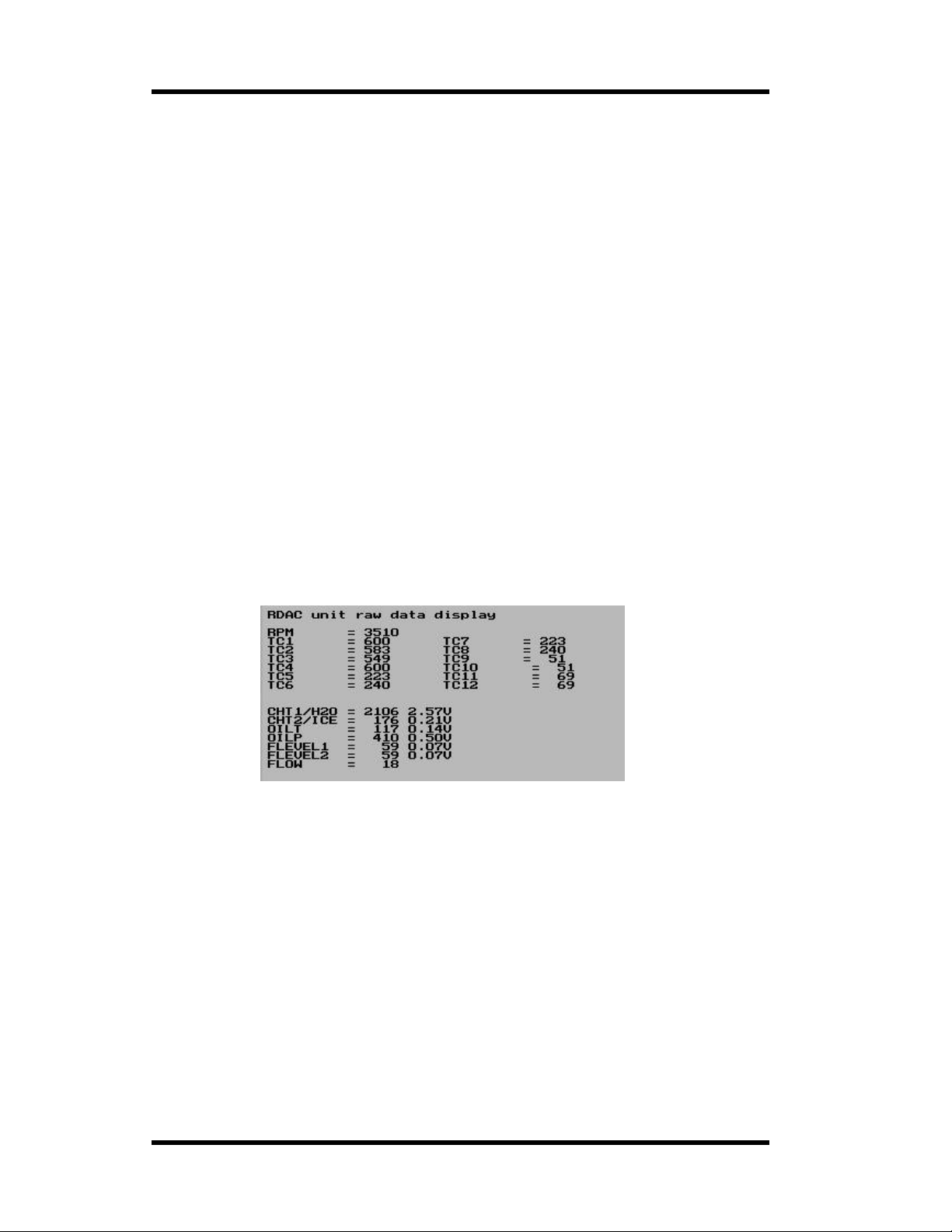
MGL Avionics Stratomaster Ultra Horizon XL Owner’s manual
Ambient temperature
Use this function to correct errors of your ambient tempera ture probe. Th ese probes may
have small erro r s up to a few degrees in extreme cases. Add a positive or negative offset in
degrees to correct for this error. Try and obtain an accurate reference thermometer to give
you the correct temperature.
Please note: Your ambient temperature probe must not be exposed to engine heat or
sunlight as this can cause it to report an incorrect ambient temp er ature. This could result in
incorrect density altitude displays.
MAP calibration
If you have a RDAC X model B or D and want to use the built in manifold pressure sensor,
use this function to calibrate the sensor.
This calibration must be perf ormed every time yo u change the RDAC and also before using
the RDAC for the first time.
To calibrate , ensure that the RDAC MAP sensor is not blocked and is open to the
atmosphere.
Obtain a read in g from the buil t in baraometer. You may need to pl ace the baromet er onto
one of the displays if it is not there already (if you have a default panel, it is on page 1).
Take a note of the baromete r rea di ng.
Now go into the MAP calibration a nd adjust the calibration number so t he value to the right in
brackets of the calibration value reads the same as the barometer.
Probe trouble shooter
This useful fun c tion shows the raw data as obtained from the RDAC unit. This can be used to
locate and interpret problems with probes and senders. Here is a typical display:
RPM refers to the time it takes between pulses a s measured on the REV counter terminal. It is an
internal unit of measure. The shorter the time , the smaller the number. A value of 31000 means:
No pulses meas ur ed within a certain time fram e.
TC channels show r aw thermocouple channel data. This is the val ue in degrees C and will be for
K-type probes. J-types are based on this number using a calculation.
The “Flow” item shows the numb er of pulses rec or ded in a certai n tim e per iod. A value of zero
means that no pulse s have been counted.
All other values are from a “analog to digital converter” or ADC. These are numbers from 0 to
4095. “0” correspo nds to “0” volts on the input and “4095” corresponds to “5” volts on the input.
All of these inputs are internally “pulled up” to 5 volts using a resistor so if you ha ve nothing
connected to such an input you should get a reading of 4095.
Assume you have a probe connected and the probe is “pulling dow n” the voltage to 2.5V (half of
5V) then the number you see would be 2048.
What would typical values for various probes be ? The following provides a rough guide:
Page 38
Page 39

MGL Avionics Stratomaster Ultra Horizon XL Owner’s manual
NTC temperature probes, standard oil or water temperature probes.
At ambient temperature: 1500 – 3000 depending on type.
At operating temperature: 50-150 depending on type.
Note that the number decr eases with temperature.
MGL precision semiconductor probe:
At zero degrees C: approximately 2228. For every degree C above t hat, add 8.2.
The count increases with temperat ure.
Values of zero (or close to that) on any of the ADC inputs may indicate a connection that is
shorted to ground while a ver y hig h number (>4000) could mean a bad connectio n or a faulty
probe.
If you suspect a faulty RDAC input, always verify this w ith a multimeter. Compare the voltage you
are measuring at the suspect ed terminal wit h the value you are getting fr om this menu function.
Page 39
Page 40
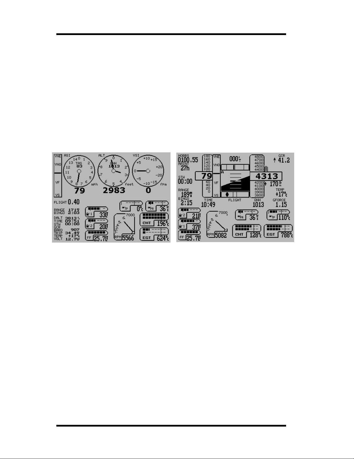
MGL Avionics Stratomaster Ultra Horizon XL Owner’s manual
Ultra Horizon XL configurable displays
The Ultra horizon provides two independent display pages. Each display page can be freely
configured to ac t as primary fl ight display, engine monitor or a combination of both.
Switching between the two display pages is done by pressing the “Select” button.
Configuratio n of either displ ay is done by first sel ecting the required display page and then using
the two system se tup functions “M ove display items” and “Enable di splay items”.
These two functions are found in t he System setup m enu.
A choice of over 50 instruments and display items is offered. Each of these can be configured
according to your needs.
Most display items offer several display options. The s e can be viewed and selected when you ar e
in “Move Mode”.
Instruments themselves offer many configurable options depending on the type of instrument. For
example a EGT gauge requires setup of applicable channels and temperature ranges.
The two images above show two possible displa y pages built using the built in sample s creens in
only a few seconds. The left screen shows the standard VFR display with a two cylinder fo ur
stroke engine c hoice. The display on the right shows the standard IF R screen usi ng the same
engine choice.
The built in sample display setups are intended as a starting point for your customization. Add or
remove items from t he screens, move items to different locations or choose differ ent display
options for any item.
Both displays would require a RD AC X engine monitor and the display on the right would require
a SP-3hc IMU/com pass sensor pack age.
The Ultra Hor izon XL allows you to create your own display layouts to suit your application and
aircraft exactly.
The following pages offer detailed descript i on of every available display item.
Page 40
Page 41
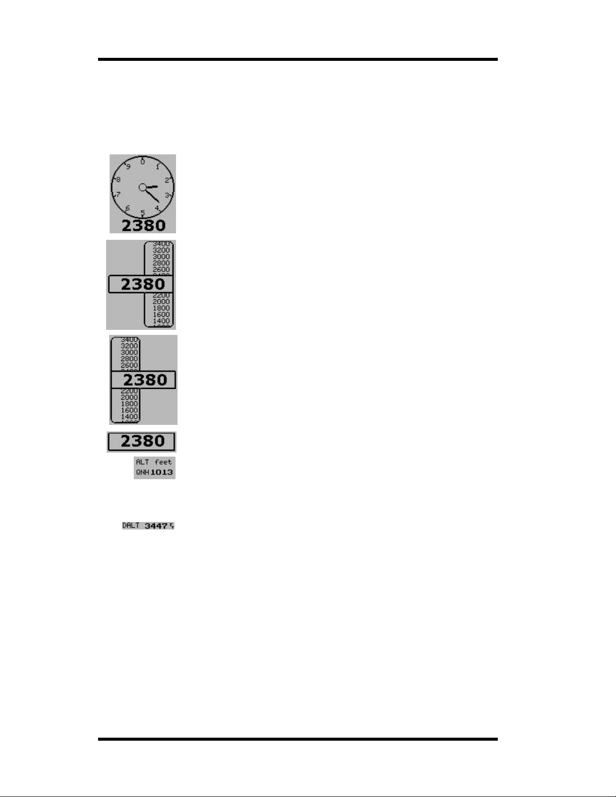
MGL Avionics Stratomaster Ultra Horizon XL Owner’s manual
The Altimeter
The altimeter measures pressure altitude from -700 to over 40.000 ft. Altitude readout can be
in feet or meter s (select in mode and units setu p).
You can select b etween four different altimeter displays.
Traditional analog altimeter
Right biased tape altimeter. This form is normally used if an artificial horizon
is used. You can select the steps used for the tape gradient to suit your
expected oper ating altitude range.
Left based tape altimeter.
Compact, numeric only altimeter . Used to save spac e in busy panels.
Four related it ems can be used with the altimeter. The QNH label sh ould be
used with the QNH display (local pressure setting). Q NH readout can be in
millibar or inch es of mercury.
Further to this you can use the ALT label and t he alt im eter unit s label. T hi s
label will show “feet” or “meter” depending on your setup.
Independent to the norm al alt imet er , you can enab le a densit y altim et er.
This consists of the label “DALT” and the dens ity altitude readout. Density
altitude takes the current am bient tempera ture into account. If no such
temperature can be measured (no probe connected), you will see the
readout “Tem p ?”
The QNH label and QNH readout (local pressure) should be located close to the altimeter. In
case of the analog altimeter, you can place the QNH items inside the altimeter.
QNH is adjusted in steps of 1 millibar (about 30 ft altitude) usin g the “+” and “-“ buttons whenever
one of the two main display pages is sho wing.
The altimeter m ay have an alarm enabled. Select t he alarm limit (altitude ceiling) in the Basic
operations setup menu. If you have exceeded the ceil ing, the altitude display will fla s h.
Page 41
Page 42
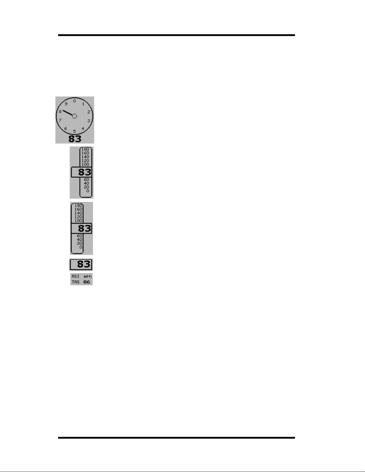
MGL Avionics Stratomaster Ultra Horizon XL Owner’s manual
The Air speed indicator
The airspeed indicator (ASI) can indicate airsp eed in mph (miles per hour), knots (nautical
miles per hour) or km/h (kilomet ers per hour). This is selected in the mode and units setup
menu. The Ultra ASI provides a range of 16mph to over 250m ph.
You can choose from four different airspeed indicators.
The traditional ana lo g airsp eed ind i cato r. You can sele ct a scale suit able for
your application. Choose from a gr ading of 80, 100 , 150, 200, 300, 4 00 units of
measure.
Tape based airspeed indicator. This is normally used if an artificial horizon is
displayed. You can select the step s between the tape gradients to suit your
airspeed range.
Tape based airspeed indicator with a left bias.
For busy panels a numeric airspeed indicator can be selected to save space.
You can enable a “ASI” label and a airspeed units readout. Further to this you
can enable a true airspeed readout and corresponding label. The true airspeed
readout is ba s ed only on the altitude, assuming a standard gradie nt. This means
that the true airspeed readout will work even if you do not hav e an ambient
temperature sen sor instal le d.
The ASI may have a l arms enabled. If the alarm is enabled, the settings for Vs (stall speed) and
Vne (never exceed s peed) will be used as limits. When the alarm is active, the ASI readout will
flash.
Note: If you have automatic flight detect enabled, the ASI readout will flash after you have landed
for a short while until the flig ht has ended (logbook entry ha s been made).
You setup the V speeds in the Basic operations setup menu.
Page 42
Page 43
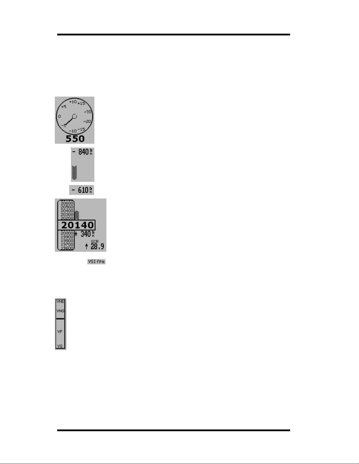
MGL Avionics Stratomaster Ultra Horizon XL Owner’s manual
The VSI indicator
The VSI (vertical speed indicator) shows your rate of sink or climb.
Readout is in fee t per minute or met ers per second depending on your choice of altitude units.
You have four different display options for the VSI.
The traditional analog VSI. This provides you with an analog range of +/- 2000
ft per minute ( or the equivalent in meters per second) plus a digital readou t t o
+/-9999 ft/minute.
Two VSI options are provided, designed to be placed on top of the altimeter
tapes. One version is provi ded for a left and one of a right bias tape altimeter
display.
For applications needing to save disp lay space, a compact numeric onl y VSI
readout can be selected.
This image shows a tape based altimeter with correctly applied VSI
readout.
Further to this the glide/clim b r atio indicator is shown toget her with the
matching “GCR” label.
Glide/climb ratio shows you the ratio between your forward airspeed (true
airspeed) and your vertical speed.
This indication is a useful feature to optimize your aircrafts glide slope.
A “VSI” label is ava ilable as well as a VS I units readout that displays either
“fpm” or “mps” d epending on your chosen altimeter units.
The VSpeed indicator
The Ultra provides a VSpeed indicator. This instrument shows your airspeed (ASI) in
relation to your defined VSpeeds. You can define the following VSpeeds in the Basic
operation setup menu.
Vs – stall speed, minimum operating speed with full flaps deployed.
Vf – maximum flap speed.
VNo – maximum maneuvering speed.
VNe – maximum allowable straight and level airspeed.
Your airspeed in r elation to the VSpeeds is indicated by the position of a horizontal bar.
The VSpeed indicator would normally be used w ith conventional three axis contr olled aircraft .
This display is of le sser value in weight shift aircraft such as trikes and of little value in Rotor craft.
If you would like to use the VSpeed indicator, we recommend to place it next to the airspeed
indicator.
Page 43
Page 44
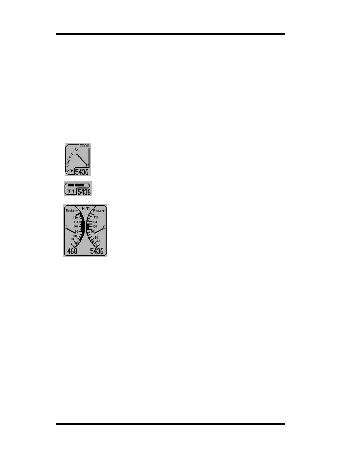
MGL Avionics Stratomaster Ultra Horizon XL Owner’s manual
The rev counter
The Stratomaster Ultra includes a very flexible rev counter that can be adapted to a very wide
variety of eng ines. In the main this is done in the Device setup m enu under “Basi c operation
setup menu” and “Calibration M enu”. Here you enter the number of pulses the rev counter
pickup (whatever it may be) will generate for every ten revolutions. The instrument will
actually use this informat ion to work out revs from the time it takes to complete ten
revolutions of the engine. This way high resolution of the rev counter is guar an teed ev en if
only one pulse is generated for a single revolution as would be the case for the 912 engine.
The rev counter is available in three variants, one of which is intend ed for rotor craft such as
small helicopters and gyro planes.
The rotor craft option shows an opposing needle display for engine power (engine RPM) and
rotor speed (or rotor RPM).
Standard RPM rev counter. The scale (maximum RP M ) can be selected i n the
Basic operation setup menu.
This smaller versi on of th e rev count er can be select e d if you have a bus y panel
and want to save some space. You sel ect the maximum RPM to display on the
bargraph in the Basic operation setup menu.
The Rotor craft opposing needle R P M and rotor speed display.
Indications can be in RPM or as a percentage relative to a given RPM
setting.
You setup most of these items in the “Rotor craft setup me nu”.
About rev counter pickups
Pickups vary from those provided by the engine manufacturers in the form of magneto coil
tapings (Rotax / Ducati) to tapi ng into the prim ary of a aircraft style magneto.
In fact, anything that is able to provide at least a 5 volt, reasonably stable signal at the rev
counter input of the RDAC EMS system. Signals with a voltage as high as 100 volts can be
used.
On unusual engines it is often a matter of experimenting with various pickup methods to find
a satisfactory solution. Once a stable reading can be obtained, set the calibration of the rev
counter so that correct revs are indicated.
The range of the rev counter is up to 9 999 revs. You should select the scale of the analog
rev counter to just above the maximum RPM. For example for a VW engine you might select
4000 RPM.
Pickups for the Rotor speed sen s or r ange from hal l effect sensors, g ear tooth sensor s to
simple magnetic switches that are closed by a small magnet once per revol u tion of the Rotor.
You setup the number of pulses ge nerated by 10 revolutions of the rotor in the Rotor craft
setup menu.
Page 44
Page 45
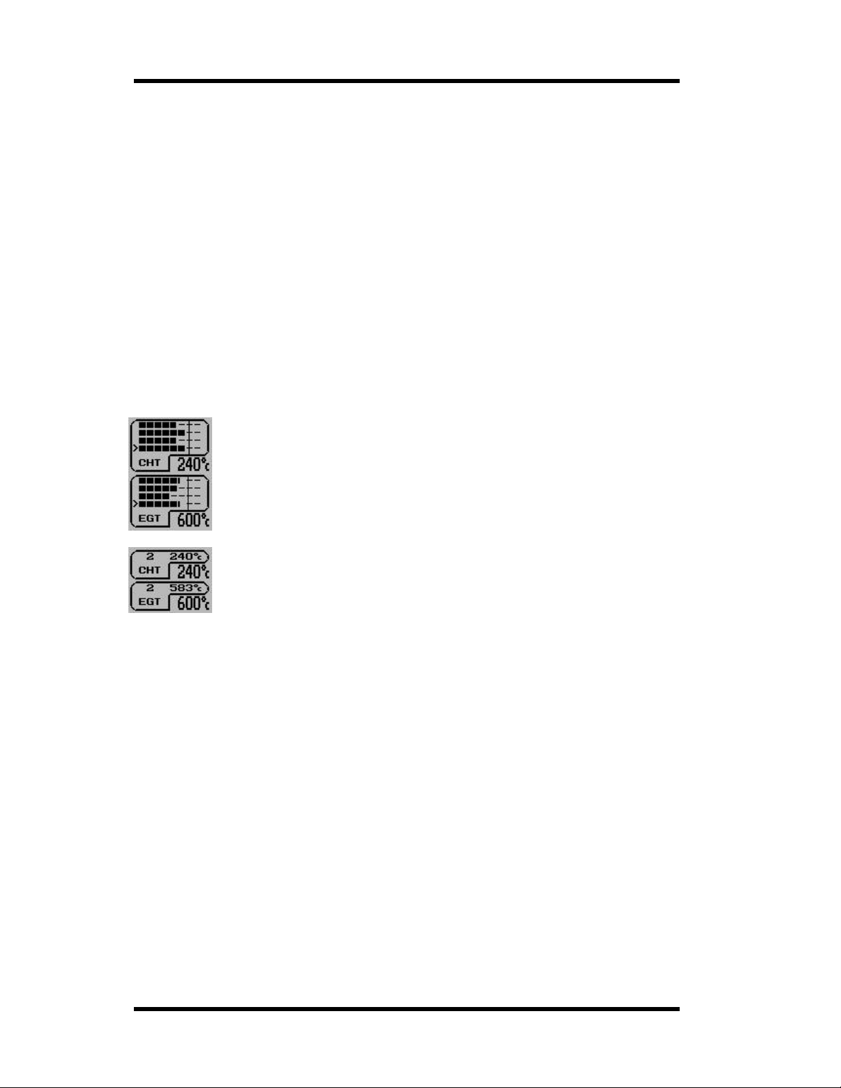
MGL Avionics Stratomaster Ultra Horizon XL Owner’s manual
Selecting between RPM and percentage for the roto r c r aft display is also done in the Rotor
craft setup menu.
The Rotor speed display may have alarms enabled for rotor lo w and rotor high RPM. You
setup the desired RPM limits in the Rotor craft set up menu. If the alar m is active, the rotor
speed display will be flashing.
EGT and CHT thermocouple display
The RDAC X engine monitoring system makes tw elve thermocouple channels available.
These inputs can be used for EGT probes (exhaust gas temperature) or cylinder h ead probes
(typically the spark plug washer types).
You determine how and if these ch annels are used in the “engine detail setup menu”.
Each EGT or CHT display pane l can op er ate in one of three m odes :
a) Full panel, numeric readout shows highest temperature
b) Full panel, numeric readout shows one channel at a time (scanning mode)
c) Small panel, scanning mode with highest temperature always shown. This option is
normally used if yo u have a busy panel, lots of channels to monitor and need to save
panel space for o ther instruments.
Example four channel EGT and four channel CHT display using the full panel in
scanning mode. The “>” symb ol is use d to in dicate the currently showing
channel.
You select numb er of channels, temperature rang es and scanning mode in the
Engine detail setup menu.
Example of a small EGT and CHT panel. This display can be used if you need to
save display space for other instruments. In this case the display shows yo u one
channel at a time (channel num ber followed by the temperature) plus a larger
readout of the maximum temperature of all channels.
You can assign your RDAC X TC chan nels to EGT and CHT probes, up to a total of 12 channels.
EGT probes always start at channel TC1. CHT ch annels start at the next avail able channel.
For example, assume you need four EGT channels and four CHT channels. In this case TC1 to
TC4 will be EGT, TC5 to TC8 will be CHT.
The only exception to this is if you have select ed Rotax 912 CHT mode (select t his in the Engine
detail setup me nu – change the nu mber of CHT chan nels until you see “Rotax 912”).
In this case, all TC channels are available for EGT while the RDAC inputs CHT1 and CH T2 are
used to measure the sta ndar d , built in Rotax 912 and Rotax 914 CHT probes. These probes are
not thermocouples but are in fact standard oil temperature senders, used to measure the cylinder
head temperature.
If you have EGT and/or CHT alarms enabled, the alarm will be activated whenever one or more
of the channels exceeds the temperature you have specified in the Engine detail setup menu .
Alarm channels will b e shown with a flash ing bargraph (large displays) as well as a flashing
temperature readout.
Page 45
Page 46
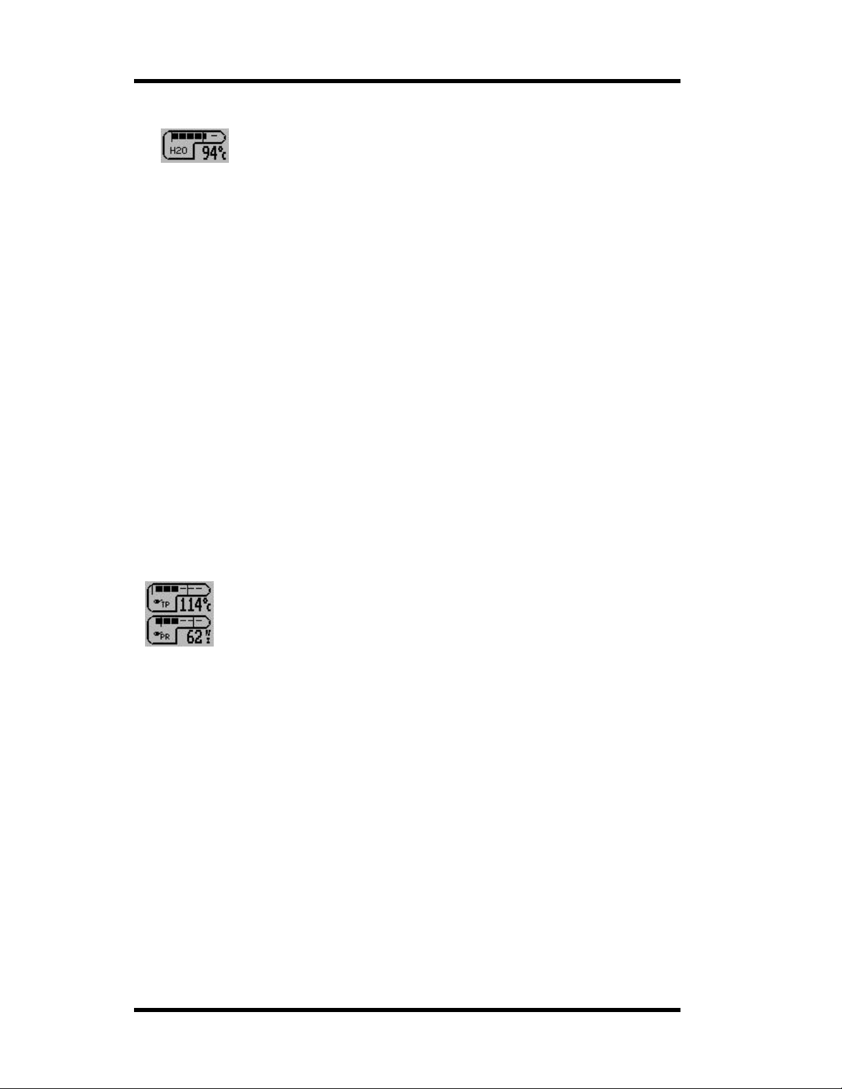
MGL Avionics Stratomaster Ultra Horizon XL Owner’s manual
Coolant temperature indicator
This instrument is used to display coolant temp erature for water cooled
engines
Water temperat ure measurements requires the sender available from MGL A v ionics. This is
a standard automotive sender with the following characteristics:
900 Ohms at 20 deg r ees C and 93 ohms at 85 degrees C.
You can also use the precision semiconductor temperature sender available from MGL
Avionics. We recommend the use of this sender for applications were you need to know the
exact water temperature.
You can also select one of the alternative temperature senders in the Sender setup menu.
When procuring oil or water temperature senders, be aware that these senders are based on
NTC resistors and typically have a fairly large tolerance. They tend to be more accurate at
higher temperatures but can have large errors at low temperatures.
We suggest that you use a multimeter in combination with the a mbient temper ature probe of
the Stratomaster Ultra to verify that you have the correct sender.
Using the Stratomaster connected to a 12V batter y or similar power supply, use the included
ambient temperature probe to measure the temperature of a jug filled with boiling water.
Insert the temperature probe in question connected to the resistance measurement setting of
your multimeter. Ensure that the top terminal of the sender remains dry to avoid
measurement errors.
Wait until the temperature drops to 85 degrees and then take a reading of the resistance. A
tolerance of up to 5% is acceptable.
Please note that you can also use the programmable probe in cases where you need to use
an existing temperature sender.
Oil temperature and Oil pressure indicato r
Two related instruments ar e oil pressure and oil temperature. These instrum ents
are often used together but they are two independent instruments and you can
enable and place them indivi dually.
Pressure is shown either in BAR or PSI as selected in the “mode and units setup menu”.
Temperature units are selected in the same menu and can be either d egrees F or degrees
C.
The oil pressure indicator
Please setup the required oil pressure sender parameters in the “Sender setup menu”.
You should setup the following items:
a) The maximum resistance of the sender ( 200 ohms in case of most VDO senders)
b) The pressure required for maximum/minimum resist ance (often 5 or 10 bars)
c) The direction of the r esistance versus t he pressure. Most senders increase resistance
with pressure but there are a few that work the other way around.
You can enable either a minimum pressure level or maximum pressure level or both for
alarm monitoring.
Please note: Should you switch on alarms for the oil pressure reading, the alarm will be
activated if oil pressure falls be low the set level. This implies that the alarm will be activated
should you switch your engine off .
Page 46
Page 47
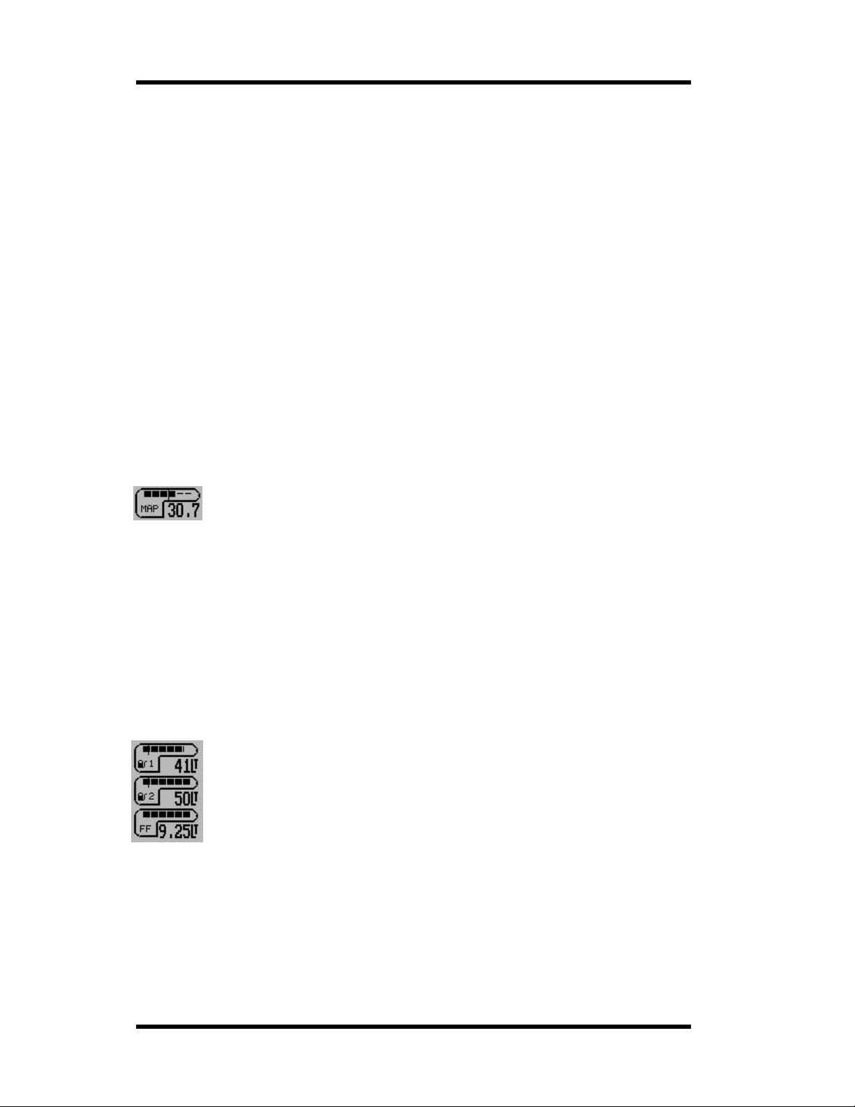
MGL Avionics Stratomaster Ultra Horizon XL Owner’s manual
Set the required alarm level in the Engine deta il setup menu (page Error! Bookmark not
defined.). Most requirements would use a minimum pressure of 1.5 to 2.0 Bars (20 – 30
PSI).
The oil temperature indicator
The RDAC EMS can interface to standard VDI oil temperature sender (these are used in
Rotax 912/914 engin es as w ell).
These senders exhibits a resistance of 100 ohms at 85 degrees C and 1000 ohms at 20
degrees C.
It is also possible to use the MGL precision semiconductor sender instead of a standard
automotive sender. This sender, although m ore expensive, is very accurate and does not
suffer from the wide tolerances of standar d automotive components. You need to select the
type of sender used for the oil pressure in the “sender setup menu”. The default sender
selected is the standard autom otive type.
The Ultra HXL a lso allows you to use Westach NTC senders as well as a user
programmable probe (here you can set the Ultra to r ecognize the characteristics of just
about any NTC type sender).
You can enable m i nimum and max imum temperature alarms for oi l temperature. Should any
alarm be active the temperature readout w ill flash.
Manifold pressure indicator
Manifold pressure is used in aircraft with variable pitch propellers to monitor and
set engine power. In turbo boo sted engines it ca n also be used to monitor the
amount of boost pressur e delivered by the turbo charger.
The MAP indicator can be setu p to give a readout in m illibars, inches of mercury or psi.
Select the required units in the Mode and units setup menu.
Manifold pressure is displayed r elative to sea level atmospheric pre ssure on a standard day
(1013.25 mill ibars). You can select the widt h of the window you would like the display to use.
For example, if you select a 100 millibar range , the bargraph wi ll show from 91 3 to 1113
millibars.
You select the di splay range in the Engine detail set up menu.
Please note: before you can use the MAP indicator for the first time, you must perform the
MAP sensor calibration as explained in the Calibration menu section of this manual.
The fuel flow and fuel level indicators
The Ultra Horizon XL provides yo u with options t o connect up to two physical fuel
tank level senders plus a fuel flow sender.
You can choose to display a single or a dual tank system, any tank level can be
based on a calcu lated fuel level if you have a fuel f low sender.
The fuel flow indicato r
If you have a fuel flow sender in stalled this instrument will show you your current fuel flow
per hour. The indication will be in liters per hour , imperial or U.S. gallons per hour. Select
this in the mode and units s etup menu.
Fuel flow rate is an important and useful indicator showing you the health status of your
engine and fue l system. We recommend from actual past experience t hat you include t he
fuel flow ra te in your pre-flight check s at engine run up time. You will soon know what fuel
Page 47
Page 48

MGL Avionics Stratomaster Ultra Horizon XL Owner’s manual
flow rates to expect from your engine at various power settings. At run-up time, run the
engine for at le ast 30 seconds to a minute at full take-off power and watch the fu el flow rate.
Should your fuel pump and r elate d s ystem not be cap a ble of sup pl yin g enoug h fuel the fu el
flow rate indication will tell you that you have a probl em before you take to the air. If the fuel
flow rate is not where you remember it should be, it is not because your engine is very
economical today but because you have a potentially dangerous problem!
The Ultra HXL is able to provide fuel flow information from an inline turbi ne sender or directly
from inform ation obtained by monitorin g your fuel injectors (fuel injected engines onl y).
Select the required source in the “ Sender setup men u”.
Please note:
You have a fuel accumulator avai lab le in th e main menu . This s hows you a total of fuel us ed
since you last reset the accumu lator.
Fuel flow send ers require correct installation and calibration in order to give you accurate
readings. Please see the relevant section in th is manual.
The fuel tank level indicators
You have two physical fuel tank level sender inputs on the RDAX X engine monitor. Each of
these can pro vi de a measuremen t of fuel level in one tank for display by the two av ailable
fuel level displays.
Each sender needs t o be calibrated before you can use it. This is done in the Fuel tank/level
sender 1 and Fuel tank/level sender 2 menu functions.
You setup tank size and sender calibration using these functions. Please also see the
separate sect ion on tank level s ender calibrat ion in this manua l.
Alternativel y, it is possible to display a calculated fuel level. In this case you need a fuel flow
sender conne ct ed. You enter a starting fuel quantity (for ex am ple after you h ave filled your
tank) and any fuel used is subt r acted from the remaining fu el quantity.
You enter the calculated fuel level in the main menu.
Fuel levels are a lso used for range calculation. You select which tanks to use for range
calculation in the sender setup menu.
You select whether to use physical level senders, calculated fuel level or both in the same
menu.
Both tank level indic ators can have alarm level s set and ena bled. You set the fuel low level s
in the Basic operations setup menu.
Fuel pressure indicator
The fuel pressure indicator can show fuel or any other liquid pressure based on the
measurement output of a suitabl e pressure sender.
The Ultra Horizon XL is optimized for any pressure sender that can produce a low
impedance 0-5V DC output, linear with applied pressure. A typica l, very good quality
pressure sender is the type A-105 with a 200psi pressure range from Honeywell Sensotec.
We recommend that you use sensors like this or similar to this as they are based on sealed
stainless steel diaphragms tha t will not be atta cked by fuels and other aggressive liquids.
You can setup the senders maximum pressure reading at an output of 5VDC. In the case of
the suggested sender, this is 200psi.
You also need to se lect where you are going to connect the sender o n th e RDAC X engine
monitor. You can choos e between CHT1/AUX3 or Fuel level sender input 2.
The above two items are selected in the Sender setup menu.
Page 48
Page 49
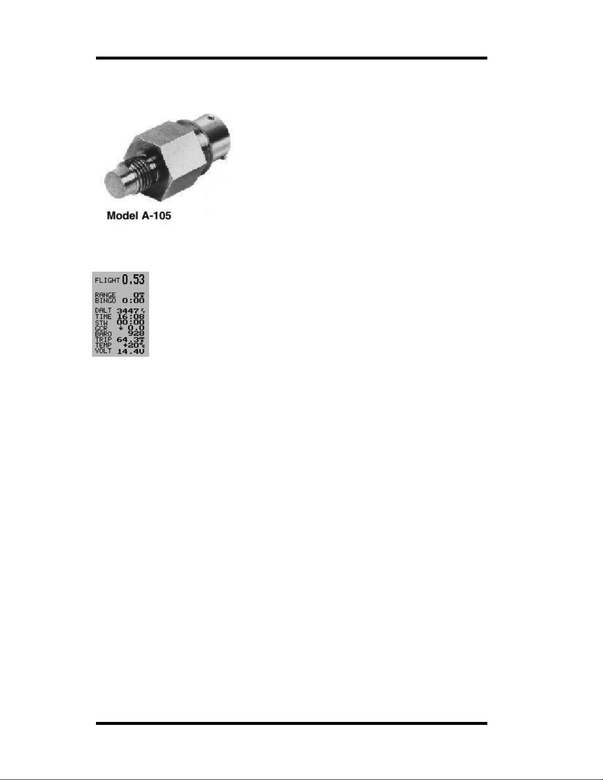
MGL Avionics Stratomaster Ultra Horizon XL Owner’s manual
You can enable an alarm, activated below a minimum pressure level. You can select the
required minimum pressure le ve l. This is selected in the Engine detail setup menu.
Example Honeywell Sensotec A-105 pressure sender
suitable for aggressive liquids.
Numeric information displays
The Ultra Horizon XL provi d es you with a numbe r of num er ic inf or mat ion item s
that you can place onto the disp la y.
Each numeric item has an associat ed label that is also an independe nt item. This
allows you to place the identifier for the numeric item at your convenience.
Each numeric item can be shown in eit her a small font or a large font. In the
sample display on the left you can see the flight time using a large font and the
remainder of t he items uses a sm all font.
The following documentation lists every available item in this category.
DALT (DENSITY ALTITUDE)
Density altitu de is press u re alti t ude corrected for air densi ty. This relates to altitude and
temperature. To use this funct ion yo u mu st instal l the i nclud ed amb ien t temp era tu re probe so
the instrument can measure the correct ambient temperature.
Density altitude is an usefu l indicator for you r aircraft’s p er formance at altitude. The altitude
given is the equivalent altitude that you should consider your aircraft to be at currently,
regardless of the actual altitude. This in turn will enable you to correctly assess required takeoff and landing distances as well as load carrying abilities. Consult your aircraft’s handbook
on relevant de-rating curve s .
BAR O ( BAROM E TER)
The barometer shows your curr ent ambient pressure. It is the basis of your alt im eter.
Why include a barometer in an aircraft – this is a question we get asked often. Here is why:
Firstly and perhaps most obviously, it has uses when predicting f r ontal systems and general
weather forecasting. Sailors use it with great effect and much the same reasons apply for
many of us aviators.
The second reason however I value as the most important: To convince you that flying too
high in an unpressurised aircraft without added oxygen is not a good idea.
At an altitude of 12.000 ft (3 658 m), considered by many as lim it for unaided ascent, the
barometer readi ng will be as little as 640 mb (18,9 Inch of Hg) even less de pending on local
conditions at the time. Furt her considering t hat at sea-level you will be at ar ound 1000-102 5
mb (29,5 – 30,3 Inch of Hg) most of the time, you should easily see that you’re going to
deprive your lungs of badly needed oxygen. Many accidents have happened as a result.
Page 49
Page 50

MGL Avionics Stratomaster Ultra Horizon XL Owner’s manual
TIME
The current tim e of day. This is set in the “Aircraft setup” menu. Should you ofte n fly in
controlled airspace you may want to set the time to read UTC rather than local time. Date and
time of day are relevant for flight information stored in the logbook. The date and time
originates from a built in crystal controlled watch with low drift characteristics. You may need
to correct the time for small drift every few months. This is done in the “user setup menu”.
FLIGHT
The duration fr om take-off of the current f l ight or the dur ation of the last flight if no flight is
currently active.
Note: We recommend that you set the instrument to “automatic flight detect” in the m ode
menu. Should yo u pr efer manual f light start and stop then the FLIGHT timer will show the
time from the manual start of a flight to its manual stop.
Manual flights are started and stopped in the r elevant menu item in the main menu.
GCR
Glide or climb ratio indicator. This useful item divides your forward distance made good by
your vertical speed. The ratio is shown as a number from 0.00 to 99.9. It should be
interpreted as follows:
Example: GCR 8.5. This means for every 1 ft (or meter) of vertical sink or climb you are
traveling 8.5 ft (or meters).
The arrow in front of the number indicates climb or sink rate. This function is useful t o
optimize glide r atio or judge the effects of changes to your airfra m e or power plant.
TEMP
The ambient temperature. Yo u need to install the included ambient temper ature probe in
such a fashion that it is exposed to the outside air. Do not install the probe inside your cockpit
or instrument pod . I nstall the probe in such a fashion that it will not be heated by engine
exhaust or sunlight. Ambient temperature is required to calculate density altitude.
TRIP
A flight distance trip counter similar to a trip counter in a car’s speedometer. The trip counter
is reset using th e r elevant menu entry in the main menu. You can also set the instrument to
reset the trip co unter automa tically at the start of a flight (m ode setup menu). The trip
counter shows the actual distance traveled through the air and does not take wind speed or
direction into a ccount. The distance is based on TAS (true airspeed) regardless of the setting
of the air speed indicator.
The trip counter is useful during navigation competitions when GPS may be banned.
VOLT
The supply voltage level to the unit. This would normally be the voltage of your battery. This
indication serves as a battery charge indicator. Should you be using a lead-acid battery
(sealed unit or open, motor cycle battery), your maximum voltage should not exceed 13.8
volts if you have a 12 volt battery or else ov ercharging and damage to your battery will result.
Many regulators ar e of poor quality and will overcharge your battery.
A voltage level of under 11 volts indicates a discharged battery. Do not discharge your
battery below this level as you will damage it.
A charged, healthy battery will have voltage levels between 12V and 12.6V when not
charged.
RANGE
Page 50
Page 51

MGL Avionics Stratomaster Ultra Horizon XL Owner’s manual
Should you have a fuel flow sender in stalled and calib r ated correctly, this field will show you
your current range given your current fuel flow, remaining fuel level and airspeed. This
function is among the most important items for the seasoned cr oss-country flyer. It allows you
to optimize yo ur aircraft’s range by choosing the be st power setting.
The RANGE estim ate is dependa nt on the quality of calibration and installation of your fuel
flow sender, as well as the correc tness of reported f uel levels in your tank. The RANGE
estimate applies for still air (no winds) using your current power setting.
Remaining fuel level can be a calcula t ed item if you d o not have a fuel leve l sen d er insta ll ed.
In this case you enter a starting fuel level in the main menu and the unit cal cu lates remainin g
fuel level by subtracting fuel used as reported by the fuel flow sender.
We recommend, should this be po ssible in your aircraft, to fit a fuel level sender.
BINGO
The fuel bingo estimate is related to the RANGE estimate. The fuel bingo estimate is the time
in minutes it will take at your curr ent power setting to reach a fuel level of zero. We do
recommend that you setu p your s ystem so the zer o fuel level corr espon ds to your fue l
reserve level. Should you not do this, BINGO will mean “engine out”, usually a condition for
heightened heart beat rate f or the Pilot. Land before you reach BINGO time, even if that
means putting down in a less desirable place.
STW
The stopwatch. Use the relevant main menu item to start, stop and reset the stopwatch. The
stopwatch is independent of any flight operation and can be used for various tasks. Often, it
can be a useful aid as leg timer during navigation c ompetitions. The range is to 60 mi nutes
with a one second r esolution and thereafter to 99 hours with a on e m inute resolut ion.
The stopwatch can be used as follows:
Activating the stopwatch
Step one: Press Menu, then press Next until cursor is on the Stopwatch menu item.
Step two: Press + to start the stopwa tch
Step three: Press - t o Zero the stopwa tch if required
Step four: Press M enu to exit
Deactivating the stopwatch
Step one: Press Menu and then use Next to select the stopwatch item
Step two: Press + to stop
Step three: Press Menu to exit
Resetting the stopwatch to zero and starting/ stopping are tw o different operations. This
allows you to stop the watch and r estart at a late r stage without clearing the readi ng if
required.
HOBBS METER
Page 51
Page 52
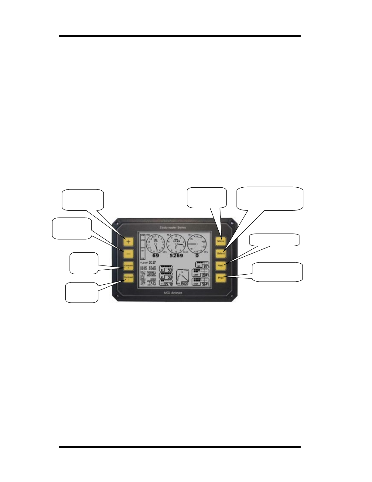
MGL Avionics Stratomaster Ultra Horizon XL Owner’s manual
g
The hobbs meter shows your engine running time. The hobbs meter is presetable to your
current engi ne tim e (U se r se tu p me nu) . En gine running time accumu la tes when the engine
revs is above the “hobbs revs” as define d in the “Basic setup menu”. This setting allows you
to ignore idle time if you so w ish .
MAINTENANCE METER
The maintenance meter is a “hobbs meter in reverse”. You set the meter to your desired
engine maintenance interval (for example 50 hours) in the “user setup menu”. When the
meter has counted down to 0 hours, your maintenance is due.
GCR (Glide or climb ratio)
Briefly mentioned in the VSI description, the glide or climb ratio shows your current ratio
between true a irspeed and verti cal speed. This reading can be used to optimize your
aircrafts glide or climb ratio.
Operating the Ultra Horizon
This describes how to use the buttons in flight whenever you see the mail screen as shown below
Increase local
pressure
settin
Enter the
main menu
Decrease
local pressure
setting
Increase
screen
contrast
Decrease
screen
contrast
Increase or decrease the display contrast to adjust the display quality to best possible setting. If
operated at tem perature extremes, this should be done whenever the temperature changes by a
large amount.
Increase or decrease local pressure setting as directed by air traffic control or to get the correct
altitude at you local airfield.
Enter the main me nu as required.
If the checklist is no t act iv e , pre ssing and holding Select f o r 5 second s wil l simul ate a total
instrument failure for training purposes.
Pressing “Next” will send a command to the SP-3h or SP-3hc sensor to instantly level the
horizon. This can be used if the hori zon is show in g inc orr ect l y after ext en d ed man ouv ering and
you do not want to wait for internal error correction to do its work. You need to fly straight and
level to use th is function pro perly.
Hold for 5 seconds to
simulate tota l instrumen t
failure (training aid only)
Set horizon level
Set or cancel pitch
offset on horizon
Page 52
Page 53

MGL Avionics Stratomaster Ultra Horizon XL Owner’s manual
Pressing “Prev” w ill add an offset to the current pitch angle displa yed so that the pitch angle will
read zero degrees. This is use d to show level fl ight at different power sett ings which may result in
different pit ch angles. The AHRS mode display will have a “P” a dded in this case to remind you.
Pressing “Prev” again will can cel t he off set.
Page 53
Page 54
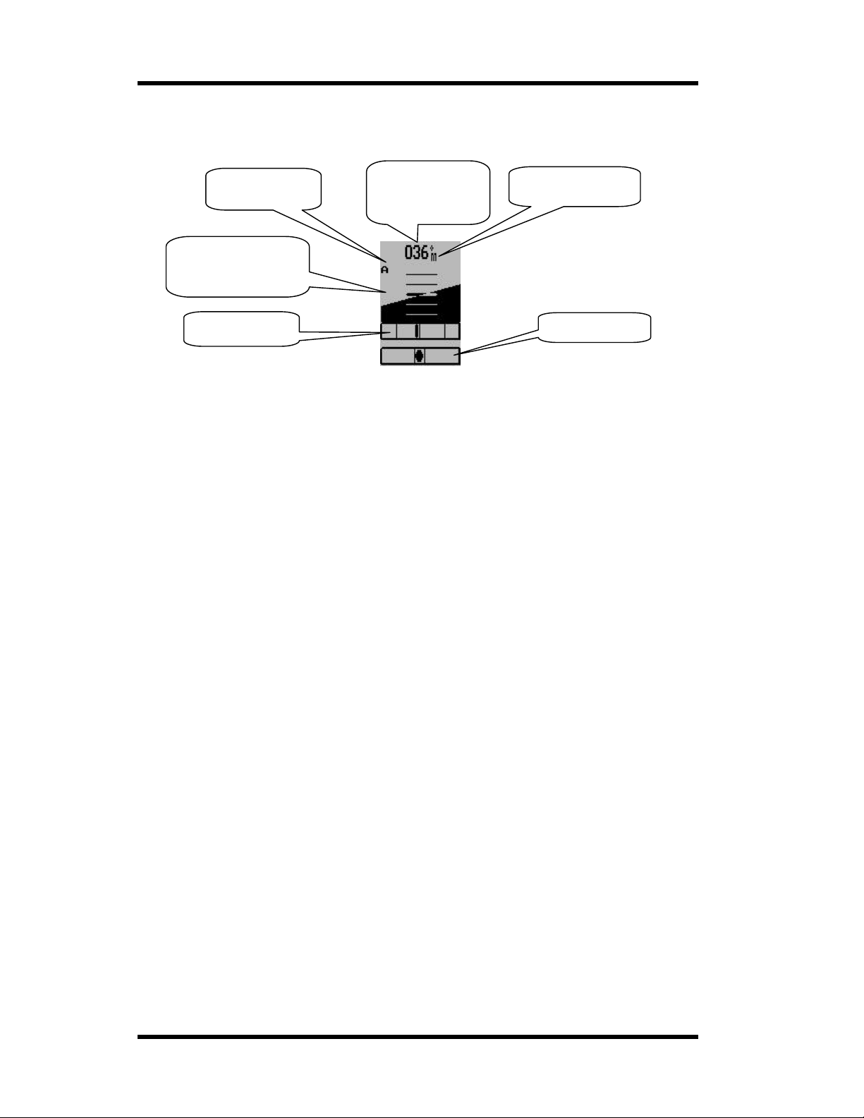
MGL Avionics Stratomaster Ultra Horizon XL Owner’s manual
r
IFR displays using the AHRS components
The Ultra Horizon offers yo u the following IF R related components:
a) Artificial horizon (attitude indicator) – requires SP-3h or SP-3hc or SP-4
b) Rate of turn indicator – requires SP-3h or SP-3hc or SP-4
c) Slip indicator – requires SP-3h or SP-3hc or SP-4
d) Compass – requires SP-1, SP-2 or SP-3hc
AHRS mode indicator
The first chara cter can be:
1) A – the AHRS is operating in acc elerometer mode.
2) G – the AHRS is operating in gyro mode.
The optional se cond character is a “ P ”. This is show n if you have pressed the “Prev” button to set
the pitch angle on the displa y t o zero. This is to remind you that you are not seeing the actual
pitch angle as measured by the IMU but have told the instrument to add an additional angle so
the display is shown with zero pitch. Pressing the “ Prev” button again will cancel this mode.
Slip indicator
This resembles a tradit ional slip indicator. It is based on the X axis accelerometer.
Turn indica tor
This gives you a marker that shows you a rate one turn (20 degrees). If the marker is aligned with
either of the two outer vertical lines then you are flying a rate one turn.
The horizon display
This shows you a vi ew on the estimated horizon. Take note that the horizon shown is a result of
thousands of calculations per second, measuring your aircrafts movement through the air. The
horizon is called estimated as it is subject to errors that may have been introduced by various
factors. Keep in mind that a IMU cannot know where the earth surface is in relation to your
aircraft, it can only estimate it.
You will find more detail on this and how to install and setup the IMU for best performance in the
manuals for the IMU.
AHRS mode
indicator
Artificial horizon
(attitude indicat or)
Turn indicator
Compass or
Gyro compass
heading
Compass mode
indicato
Slip indicator
Page 54
Page 55
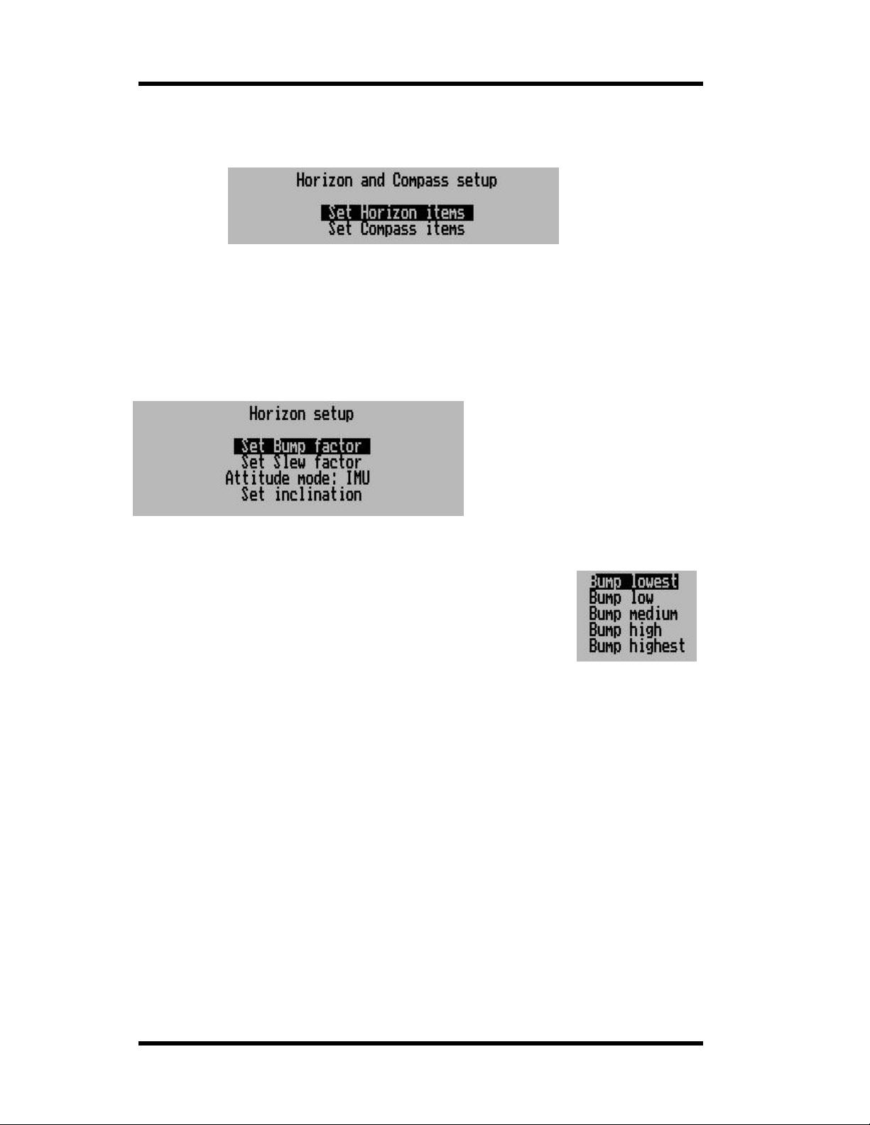
MGL Avionics Stratomaster Ultra Horizon XL Owner’s manual
Compass and Horizon setup
This menu is accessible from the main menu.
Here you will find various functions to setup and calibrate your SP-1, SP-2 or SP-3 sensor
package.
This documentation should be read in conjunction wit h the documents for the various sens or
units.
Horizon Setup
Set Bump factor
This function presents you with a small menu. You can send one of five
settings to your SP-3. This function will only work if you have a SP-3
connected. The setting is stored in the SP-3, the highlighted entry that is
shown is NOT th e setting in the SP-3, only the setting that you want to
send to the SP-3. The SP-3 stores the setting in permanent memory, the
setting is not lost if you remove power from the unit.
This filter has five settings: Lowest, Low, Medium, High, Hi ghest.
This filter sets the threshold that determines un-accelerated flight. It can be viewed as a limit on
the acceleration force actin g on the aircraft below which the gyro derived attitude will be corrected
by the attitude as derived from the accelerometers.
Typical settings are Low or Medium. Other settings may be useful in some environments.
Effect of too low setting:
System will never or only very seldom have the opportunity to correct errors. Continuous
turbulent fl ight will require a higher setting.
This setting is normally chosen on the mass of your aircraft and how it behaves with turbulence.
The more stable your aircraft , the lower a setting you can choos e.
Effect of too high setting:
System remains in “accelerometer” mode too long. The most noticeable effect this has is during
very slow entr ies to banks – the displayed horizon may show horizontal even though you have
banked or the bank angle is shown to o shallow. As the hori z on is now wrong , the error will grow
quickly as gyro rate information w ill be misinterpreted.
Set Slew factor
This function presents you with a small menu. You can send one of five settings to your S P - 3.
This function will only work if you have a SP-3 connected. The setting is stored in the SP-3, the
Page 55
Page 56
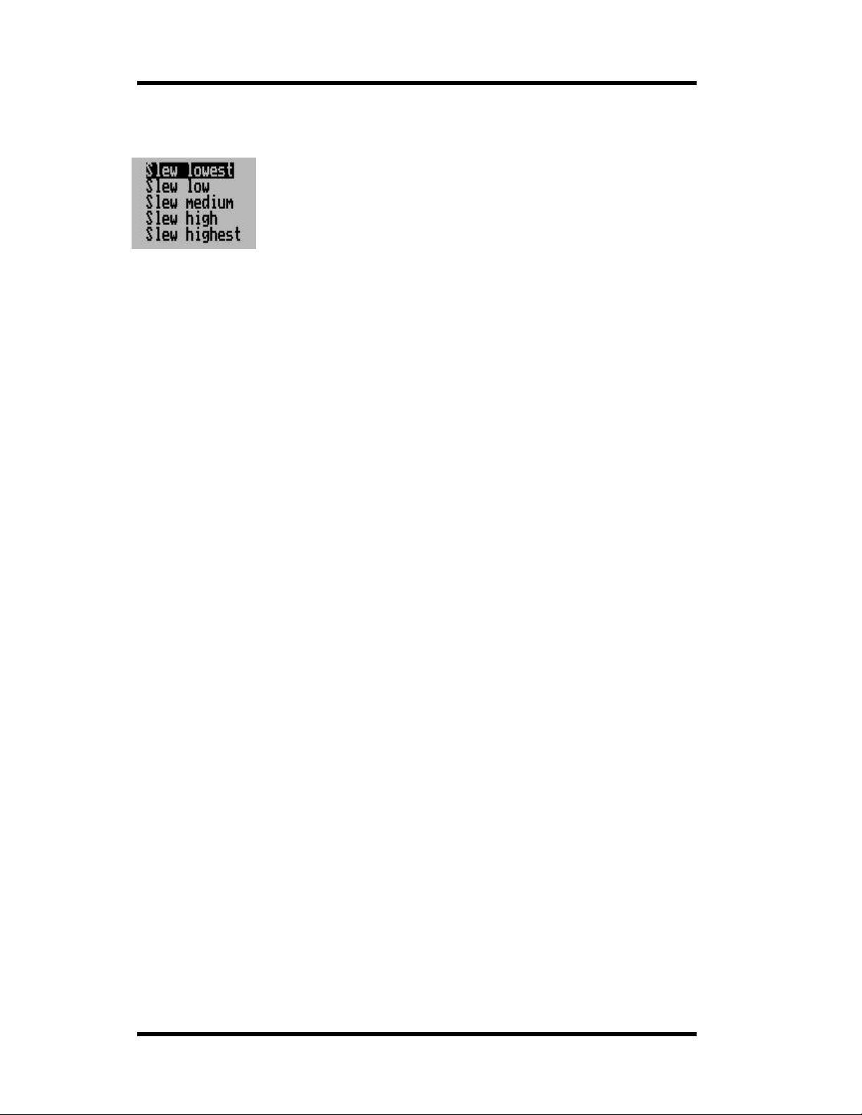
MGL Avionics Stratomaster Ultra Horizon XL Owner’s manual
highlighted ent ry that is shown is NOT the setting in the SP-3, only the setting that you want to
send to the SP-3. The SP-3 stores t he setting in permanent memory, the setting is not lost if you
remove power from the uni t.
Like the “Bump” filte r , the “Slew” filter also has five settings:
Lowest, Low, Medium, High , Highest.
This filter setting affects the speed at which error corrections take place.
Good settings are usually Low, medium or high.
This filter sett ing interacts somewhat with the Bump setting. Sh ould you find your installation
tends to accumulate errors quickly (for example you may have unavoidable vibration affecting the
sensors), set the error correction speed higher.
Do not set the error correction speed unnecessarily high as this may degrade your systems ability
to correctly detect very slow entries t o banks.
Finding the right filter values
Once good filter values are found, they are rarely if ever changed.
Good filter value selection will result in the system remaining in accel erometer mode (indicated
on your screen) for most of the tim e durin g straight and level flight.
Slow entries into banks are the most critical factor, so try these in calm conditions. Bump factor
too high or Slew factor too high (or both too high) may result in bad detection of this maneuver.
Select the Slew factor such that any errors that have accumulated during a full 360 turn at 30
degrees of bank are corrected q uickly after you ro ll out straight and level.
Attitude mode
Here you can select the type of attitude calculations you want to use.
The choice is between “IMU” and “Mattitude”. The display shown indicates the cu rrent mode of
operation if you have the SP-3 connected.
Please read the documentation on the SP-3 for detail of which mode you should choose.
“Mattitude” is an experimental system at this point in time, “IMU” is the normal way a strapdown
artificial horizon works.
“Mattitude” will not work corr ectly if your air craft has a signifi cant effect on th e direction an d
strength of the measured Earth magnetic field.
Please note that before you can use this mode, you ha ve to set the magnetic inclination at your
location (described below).
Attitude determina ti on modes
The SP-3hc unit provides the user with a choice of two different modes to obtain aircraft attitude
(bank and pitch).
IMU attitude determination
This mode is the traditional IMU consisting of three gyros and three accelerometers. Gyros
provide rate of turn information while the accelerometers are used to vector gravity in order to
compensate for gyro drift and also to set the initial orientation of the quaternion.
Magnetometer based attitude determination
This method uses the magnetic vector direction in three dimensions to obtain a relative attitude
that can be used as bases for determining attitude relative to the earth surface.
The SP-3hc will automatically obtain the magnetic inclination (dip angle) regardless of its own tilt
relative to the earths surface. This measurement needs to be done very accurately. The SP-3 will
perform this measurement about once every 10 seconds provided the aircraft is providing a
stable enough platform. (benign flight conditions).
Page 56
Page 57
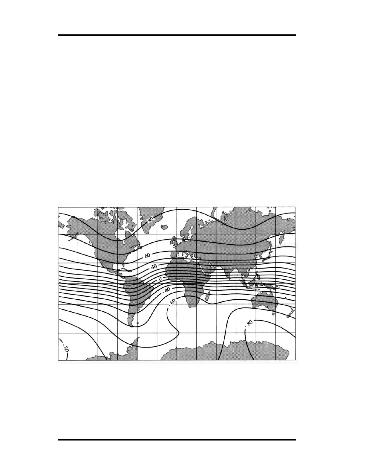
MGL Avionics Stratomaster Ultra Horizon XL Owner’s manual
The magnetic inclination does not change by a large amount over a large distance, however
small local variations of the inclination angle do occur in some locations and it is these variations
that the SP-3hc will attempt to track.
The SP-3hc provides a func tio n that al low s the user to set the defau lt ma gnet i c inclination. This
functions needs to be used at leas t once and may have to be repeate d should the SP-3hc be
operated in an ar ea with a diff er ent magnetic inclination.
No knowledge of the inclination angle is required by the user during this process as the SP-3hc is
capable of measuring this angle.
Set inclination
Use this functi on to set the magnetic inclinati on at your location. The aircraft has to be steady and
stationary. Ensure that you have moved away from metallic str uctures such as a ircraft hangers or
reinforced concrete aprons.
Selecting this function will r eturn the angle of inclination (zero degrees is straight up/down, as you
would get at the magnetic pol es). The SP-3hc needs to be connected for this.
The inclination is only needed if you want to use the “Mattitude” mode. Should you move to an
area with a different angle of inclination, you should repeat the procedure.
Note: Set the inclination only after you have performed the deviation compensation.
Compare the angle derived with what it should be, should you not get an acceptable result, you
may have to relo cate the SP-3 as it is measuring a ma gnetic field with significant deviation,
probably due to metal effect of your aircraft.
Map of the Earth sh owing isobar lines of magnetic inclination.
Page 57
Page 58
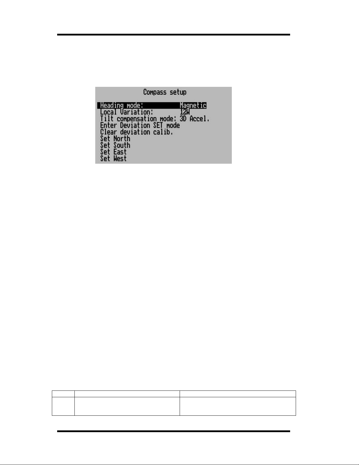
MGL Avionics Stratomaster Ultra Horizon XL Owner’s manual
Compass Setup
In this section of the Ultra menu system you will fin d the com pa ss setup funct ion s and items you
need for deviation compensat ion and calibrat ion.
Heading mode Magnetic / True
Select if you would like the instrument to display magnetic or true heading.
If you select true heading, yo u need to enter the correct magnetic variation for your locati on. You
can find your local variation on aeronautical or maritime char ts.
The heading displays will be au gm ented with °M or °T depending on the mode you have
selected.
Local variation
Enter the magnetic variation of your location. This is only used if you would like the in strument to
display true heading. True heading is the he ading relati ve to the geographic north pole. Magnetic
heading is the heading relative to the magnet ic north pole.
Variation is expr essed in degrees ea st or west.
Please note that should you move a long distance, you may have to update th e variation setting.
This setting may be ignored if you only use the magnetic heading disp lay option.
Tilt compensation mode
Select the mode you would like your compass to operate under.
2D – this mode selects a two axis compa ss system. This has n o tilt compensation.
3D A – this mode selects a three axis co m pass system. Tilt compensation by means of gravity
vectoring via accelerometers.
3D G – this mode selects a thre e axis com pa s s sys tem. Tilt compensation by mean s of
information supp lie d b y an artifi c ial hor i zon.
SP-3hc can be used with any of the above modes.
SP-2 can be used in modes 2D or 3D A. 3D G is available if an external artificial horizon is
connected.
SP-1 can only be used in 2D mode.
Each mode has advantages and disadvantages over other modes. Briefly, these are outlined in
the table below:
Mode Advantage Disadvantage
2D Most accurate as long as compass
remains level. Not affected by turns or
acceleration pr ovided compas s remains
Large heading errors when compass is tilted.
The magnitude of these errors is dependent
on the heading, type of tilt (pitch and/or
Page 58
Page 59
MGL Avionics Stratomaster Ultra Horizon XL Owner’s manual
level during tur ns. bank) as well as location on Earth.
3D-A Self-contained tilt compensated
compass. Will compensate for most tilt
errors up to 60 degrees of tilt.
3D-G Can prov ide for accurate heading even
during turns as tilt compensation is
based on gyro deriv ed hor izon.
Enter Deviation SET mode
Enters the deviation acquisition mode. Plea se read the text on the procedure to use.
Clear Deviatio n calib.
Clears any previous deviation compensation and returns the instrument to factory calibration.
Cannot correctly compensate for tilt dur ing
any form of turn due to centrifugal forces
acting on the a ccelerometer s.
Can show very large errors should the
horizon infor m ation be invalid w hich could
have a number of causes suc h as exceeding
operational limitations of the horizon system.
Set North, South, East, West
Once you have com pleted the deviation compensation, you may want to remove remaining errors
from the four main headings.
Point your air c r aft exactly North, East, West or South and select the corresponding button. The
compass system will store a correction value that will be used when you fly these headings. For
other headings the correction factor is interpolated based on your settings.
This function should be handle d with care and only after you have performed deviation
compensation as outlined below.
Using the deviation compensation feature
When you install your compas s senso r pack age, it may be surr oun ded b y sever al items or
materials that in some way cha nge the strength and direction of the earth magnetic field that your
sensors are measuring. If left unattended, this may contribute to considerable error s i n the
heading as indicated by your instrument.
Due to the magn etic sensor not being based on a magnetic item (such as a magnetic needle) as
in a normal compass, the effect of deviation is lessened a little. This is because the needle in a
magnetic compass will be attracted by iron, even if the offending iron has no effect on the
magnetic field (i.e. does not change the field directio n or strength in a hypothetical case) .
Deviation needs to be corrected if you intend using the compass for navigational purposes. The
procedure for this is traditionally called a “compass swing”. Often, two small magnets are placed
close to the compass in an effort t o correct some of the lar ger errors. Smal ler , remaining er r ors
are then noted on a “ deviation char t” and this is pl aced next to the compass for future re ference.
With the SP-1,2 and 3, a very simple method can be used to correct for most of the deviation th at
may be present in your aircraft or vehicle.
However, before you start, ensure that the sensor package is installed as far away as possible
from any of the following:
a) Ferro magnetic materials such as Iron, many steels and soft magnetic materials such as
ferrites. Any ma gnets must by located as far away as possible from the sensor package.
This includes electromagnets as used in solenoids, electrical motor s and relays.
b) Cables containing large electrical currents. DC currents will cause magnetic fields around
the cables which will lead to deviation. AC currents cause fluctuating magnetic fields that
may reduce your compass resolution.
c) Be aware that some lower grades of st ainless steel may be ferro magne tic.
If in any doubt, use a small magn et to te st an y meta ls surr ound ing the sensor package.
Page 59
Page 60
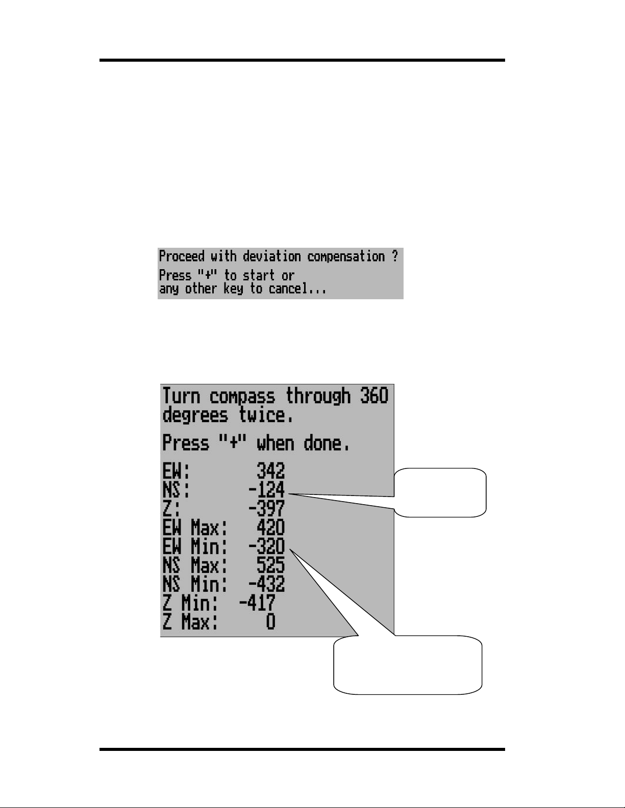
MGL Avionics Stratomaster Ultra Horizon XL Owner’s manual
We recommend to m ount the sensor package using glued on strips of velcro mater ial. This allow s
for easy alignm ent of the sensor package horizontal to the earth magnetic field.
Never perfor m the deviation c om pensation procedure or a compass swing if your aircraft is
placed on a reinforc ed co ncr ete apron or tarmac. The steel that may have been used to reinforce
may have a very significant effect on the strength and dir ection of the magnetic field at yo ur
location.
To start the deviation compensation procedure, enter the menu and se lect “Deviation SET”. You
will see the following display:
Place your aircraft in flight attitude. For example, if you own a tail-dragger, raise t he tail. Some
tricycle gear aircraft may need to raise the nose gear slightly. The object is to place the sensor
package as close to horizontal att itude relative to the earth’s surface as you can.
Press the “+” key or have an assistant do this for you if you are busy holding up your aircraft’s tail.
Press “+” to start t he deviation compensation procedure.
You will now be pr esented with the following dis play. Please note that you have to have a SP-1,
SP-2 or SP-3hc conn ected or else the display will not show and you will be directed back to the
menu.
Maximum readings in each
direction – these values will
be used for the deviation
compensation.
Current
magnetometer
sensor readings
Page 60
Page 61

MGL Avionics Stratomaster Ultra Horizon XL Owner’s manual
Place your aircraft in flight attitude. For example, if you own a tail-dragger, raise t he tail. Some
tricycle gear aircraft may need to raise the nose gear slightly. The object is to place the sensor
package as close to horizontal att itude relative to the earth’s surface as you can.
Press the “+” key or have an assistant do this for you if you are busy holding up your aircraft’s tail.
Proceed as instructed and turn the aircraft through a full 360 degrees at least once . Allow this
procedure to take so me time , pe r haps a minute. You can proceed to tur n your ai rcr aft though two
or even more tur ns but you need t o fully complete at least one turn.
You will see the instrument tracking minimum and maximum values for each sensor and you can
see the current values.
Once you have completed your turn(s) , press “+” again to inform the instrument that you have
finished.
Your instrumen t will at this point calculate a b est possible fit of the sensor data to a 360 degree
arc taking the relativ e strengths and offsets of the magnet ic fiel d into ac count.
This procedure can resu lt i n remark ably good overall perfor ma n ce of your com pa ss.
Please note: After this procedure has been completed, you may have to verify the compass
performance by performing a normal compas s swing. Should any deviation rem ain, you need to
note this on a de viation card and place this card next to the compass.
This may be a lega lly required procedure in your c ountry for your air craft class. Please check
your relevant re gulations.
Deviation compensation and compass swing may need to be repeated from time to time as the
magnetic proper ties of metals in your aircraft may change over time.
Page 61
Page 62

MGL Avionics Stratomaster Ultra Horizon XL Owner’s manual
CARING FOR THE STRATOMASTER ULTRA
Pitot tube
Dust etc. can cause a blockage in the pitot tube. Such blockage will effect the operation of
the pitot tube which will in turn affect the accuracy of the ASI/TAS readings. We recommend
that the pitot tube be cover e d when t he air cr aft is not i n oper a tion .
Cleaning
The Stratomaster Ultra can be cl eaned by wiping it with a damp cloth. A mild soap may be
used if necessary.
Take care not to wet the instrument excessively.
Do not use chemicals e.g. petrol, spirits, turpentine when cleaning the instrument.
Never clean the non-reflective display lens with abrasive cleaners or cleaners containing
solvents as this will destroy the lens coating.
Calibration
The Stratomast er Ultra instrument does not req ui r e re-c al i bration if it is used in normal
operation.
Stratomaster I nstruments used as referenc es to calibrate other instrumen ts may be sent in
for periodic calibration to MG L A v ionics. For this application we recommend a two year
calibration interval. Please contact MGL Avionics for details.
Altimetry
This section is inten ded to clarify how an altimeter wor ks and what determine s its accuracy in
simple terms.
As you know an al timeter is a simp le absolute pre ssur e gauge. This means it measures the
pressure of the surrou nding air re lativ e to abso lute vacuum as yo u would find in o uter spa ce.
Ordinary, well made altimeters ar e intricate mech anical devices that can achieve v ery good
performance . However, the s e are subject to a whole host of influences that introduce erro r s
in the readings. Vibrations tend to wear out t he tiny gears, temperature has an effect on the
elasticity of the materials used and therefore has a direct influence on the reading. The
quality of the vacuum has a direct bearing on error s and the maximum altitude the instrument
can indicate with a reasonable error.
The Stratomaster Ultra is based on a silicon pressure sen s or . In principle, these sensors are
subject to many of the problems that affect ordinary mechanical instruments and many digital
altimeters have poor accurac y a nd r esolution.
What is different in the Stratomaster Ultra?
The Stratomaster Ultra employs the most accurate absolute pressure sensor available. This
sensor is not cheap or simple. It starts with a tiny cavity in a silicon chip. This cavity is about
3
¼ mm
that is only a few thousand atoms thick. The air pressure on the one side of this memb r ane
bends the membrane towards the va cuum cavity. This introduces tiny changes in the
in size and conta ins a near perfect vacuum. It is sealed with a very thin mem brane
Page 62
Page 63

MGL Avionics Stratomaster Ultra Horizon XL Owner’s manual
electrical properties of the membrane. These changes are measured. Temperature effects
on the membrane are taken into account by measuring the temperature on the membrane
and compensating for known effects. Durin g manufacture of this sensor, the membrane is
exposed to a focused electron beam that, atom by atom removes material from the
membrane until the sensor reads exactly the cor r ect value. The Str atomaster Ultr a then
converts this reading into digital form. But the results are not taken for granted. The
Stratomaster U ltra attempts to measure the signal to levels belo w those created by thermal
noise. This electrical noise is caus ed by the vibrati on of atoms. The Str atomaster Ultra knows
the characteri stics of this unwanted signal and eliminates error s caused by this si gnal. In
addition, the Strato ma st er Ultra m eas ure s the temperature surrou nding the se nsor and
compensates for any remaining temperature induced error. This compensation is different
from sensor to sensor as it depends on tiny, remaining manufacturing tolerances of the
sensors. But your instrument knows the behavior of its sensor and can cor r ect for errors.
Once the pressure of the surrounding air has been accurately determined, how does one
calculate the altitude? Is atmospheric press ur e not supposed to change with t he local
weather as well?
Well, there you have it: All this accuracy and then a storm comes in a nd all is lost.
Back in the beginning of flight, (sometime after the Wright Brothers did the silly thing of
inventing powe re d fli ght), it was thought that it woul d be a good ide a to have some i ndication
as to how high one was flying . Ea rly , primitive altimeters whe r e b as ed on pr in c i ples much like
we use today but were very crude and what was more disturbing, they depended on each
manufacturers interpretation as to how pressure changes with altitude.
We all know that pr essure gets less as w e increase our altitude. But by how m uch? The
American National Standards Inst itute and other standards bodies came up with the idea of
simply dictatin g how the atmospher e behaves. So AN SI created the “standard atmosphere”
which was valid on a “standard da y”. The “standard day” was decreed to be a day at mean
sea level with a temperature of 15 degrees Cel sius (59 degrees Fahrenheit). Further to this it
was decided that the temperature would decrease at a certain rate as we increased our
altitude. All of this and a portion of maths would now determine how our altimete r should
work. Of course, suitable “fudge factors” were used to make the ma ths agree with what could
be implemented using a bunch of mechanical gears.
Page 63
Page 64

MGL Avionics Stratomaster Ultra Horizon XL Owner’s manual
So, the formula to use became:
P=P_0*(1-6.8755856*10^6*H)^5.2558797
Where:
P= pre ssure
P_0= pressure at sea level (10 13.25 mb on the “s tandard da y”)
H= height in feet above mean sea level
This formula is used to a level of 36.000 ft (10 97 5 m) . Above that a different formula is
used.
Now what does all of this mean to you?
It means you have an exceedingly accurate altimeter that implements the ANSI standard in
detail. It does not mean that your altitude is correct as indicated !
Your local pressur e is determined by many factors, temperature and weather are only a few.
All of these influence your alt itude reading. Place your Strato master Ultra on the ground and
run it for a whole day. Notice sli ght changes in the altitude (perhaps up to 60 ft ( 18 m) or
even more?). These are caused by local changes of atmospheric pre ssure.
These are some of the reasons the altimeter has a QNH setting. This is si m ply a correction
factor that is entered into your al timeter to correct for current local atmospher ic conditions. As
long as all altimeters use the same QNH they should all read the same altitude. This is all
that aviation requ ire s.
Should you be interested in your actual altitude, we recommend using a GPS. It is pr obably
the most accura te m eth od av ailable today. Howev er, it is not suitable f or use on an aircraft
due to the inabil ity to display a ltitude according to ANSI standar ds and local QNH settings. It
is important that all air cra ft fl y to a comm on alt itu d e ref e ren ce, even if is not correct.
True airspeed (TAS)
The Stratomaster Ultra instrument can indicate true airspeed. TAS is used for most intern al
calculations where air distance is of importance.
What is TAS and how i s it calculated?
TAS is indicated airspeed (ASI) co m pensated for altitude and temperature. Often pilots
ignore the effect of temperature and only take altitude into account when converting ASI to
TAS. For practical purposes this is quite accurate and gives a good reflection on your true
airspeed. Keeping in mind that ASI measurement is subject to errors caused by airflow
around your aircraft, there seems little point in taking this calculation to absolute resolution.
Again, we have decided to use a formula often used by pilots. This way the instrument
reading will agree with what pilots are used to.
Based on Worthingtons 13
Add 1.75% of IAS per 1 000 ft (304.9 m) increase in altitude above sea leve l.
We assume here that I AS = RAS (rectified air speed).
The Stratomaster Ultra applies the above rule but works it at a fin er r esolution of 100 ft
(30.5m).
th
edition page 349:
Page 64
Page 65

MGL Avionics Stratomaster Ultra Horizon XL Owner’s manual
WARRANTY
The Stratomaster Ultra is guaranteed against faulty workmanship on the part of MGL
Avionics for a pe riod of 12 months from date of pur chase. MGL Avio nics may at their
discretion decide to either repair or replace the instrum ent. MGL Avionics will provide free
labor and parts. Courier costs or postage costs will be for the account of the purchaser.
Please note: Certain parts are subject to breakage by misuse or external influences that
cannot be covered by any warranty.
In particular t h e following possible damages are excluded:
• LCD display – glass cracked du e to mechanical damage or freezing of the liquid crystal. The
LCD must not be exp osed to temperatures below –20 degrees Celsius (- 4 degrees
Fahrenheit) or above +80 degr ees Celsius (176 degrees Fahrenheit).
• Any damage due to unusual events e.g. aircraft crashes, hard landings, dropping the
instrument, excessive G forces, excessive vibration.
• Exposing the instrument to incorrect power supply voltages, such as connecting the
instrument to mains power supply, any voltage in excess of 30 volts DC, and any AC voltage.
• Connection of unqualified or incorrect devices. Please contact us before you connect
anything unusual to this instrume nt.
• Destruction of t he air-talk link due to connecting the unit to PC’s with unconnected earth
leads or leaky power supplies.
• Damage due to excessive static discharge.
• Damage due to lightning stri k e.
• Damage due to overpressure of any sensors, in particular ruptured silicon diaphragms due to
overpressure or mechanical action.
Any signs of opening the instrument or tampering with any of the int ernal parts will invalidate
the warranty.
MGL Avionics end eavors to repair any faulty unit whether inside or outside of the warranty
period speedily and at the lowest possible cost. Your first stop in case of a malfunction shou ld
be the dealer were you bought the instrument. It m ay be possible to repair your instrument
without it having to be shipped to us.
DISCLAIMER
MGL Avionics cannot be held responsible for incidents or damage by whatsoever nature
caused by incor r ect fuel level indication. In stallation and operation of t he instrument a nd its
related parts is outside our spher e of influence and control. W e do not manufacture eit her
the fuel level sender or the fuel flow sender and are not appointed agents of either.
MGL Avionics cannot be held responsible for incidents or damage by whatsoever nature
caused by incorr ect readings, displays, installation or operation of the instrument.
Operation of the Stratomaster Ultra instrument is the responsibility of the pilot in command of
the aircraft. The pilot in command has to make himself/herself familiar with the operation and
limitations of t he Stratomaster Ultra instrument before comme ncing ground or flight
operations as well as all other aspe cts of operation.
The Stratomaster Ultra intended for operation by a licensed pilot who is the holder of a MPL
(Micro light pilot license) or PPL (Private Pilot license) or the equivalent thereof. The pilot
should further be rated on the a i r c r aft type on whi ch the Stratomaster Ultra is being operated.
The Stratomaste r Ultra has not been submitted to the CAA or FAA or any of its agencies for
any form of certi fication. Operation and installation of this instrument is subject to the
relevant rules and regulations of your country and flight authority.
Page 65
Page 66

MGL Avionics Stratomaster Ultra Horizon XL Owner’s manual
If any of the above is not acceptable to the pilot in command he/she must refrain from
operating th e aircraft or r emove the Stratomaster Ultra from the aircraft before
commencing aircraft operations.
Page 66
Page 67

MGL Avionics Stratomaster Ultra Horizon XL Owner’s manual
Installation manual for the Stratomaster Ultra “H”
Introduction
Before you commence any attempt at installing this instrument it is your duty to familiarize
yourself with the relevant aircraft equipment installation requirements and regulations of your
country. Proceed only if you are certain that you are permitted to install this instrument or seek
approval from the required aut horities. Also not e that in some count ries only approved persons
may perform the installation of this instrument .
This instrument has not been submitted to CAA or FAA approval of an y kind. Although this
instrument surpas se s al l know n specifi cat io ns, it has not been the m anu fa ctur ers intention to
submit this instru m ent for approval due to the large co sts involved. In addition, the instr ument is
targeted for aircraft classifications that do not requir e or warrant su ch approval.
In particular the instrument is intended for use with:
• Home built or amateur built aircraft
• Experimental aircraft
• Microlight and Ultralight aircraft
• Aircraft not falling in an y of the above cat egor i es that ma y use non- cert if ie d instrum en ts
• Aircraft having obtained special flight permits specifying the use of this instrument
Please note:
You should perfor m the followin g settings after installation:
1. ASI /V SI zero pr oc edur e .
2. Set the date and time.
3. Change any other settings as required.
4. Ver if y that Al ti mete r cor re c tion and ASI gain are set to the value s gi ven in the cali br at io n
certificate of t his instrument
All mode setups are permanent and do not rely on a battery.
Values that may be affected by a low battery are:
• Date and time (real time clock)
• Current fuel level if you use the calculated fuel level using the fuel flow sender
• Hobbs and maintenance timer
• Current flight details if the flight was not yet logged due to a power failure in flight
This unit is fitted with a Lithium battery. The expected lifetime of this battery is 10 years. A
suitably qual ified electronics technician should do replacement of this battery.
The above image is the rear panel of the Stratomaster Ultra. At a minimum, you need to connect
a 8V to 18V DC power supply, usually a 12V battery fitted to your aircraft.
In addition you should fit the included ambient temperature sender and connect an optional alarm
indicator lamp. Su itable lam ps are avai lab le as “pilo t l ight s” or “panel lig ht s” from elec tr oni cs or
automotive supplies.
The following pages show the r ecommended connections one item at a time. Proceed with your
installation according to your requirements.
Page 67
Page 68
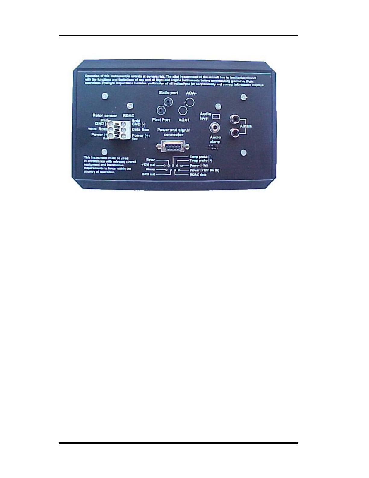
MGL Avionics Stratomaster Ultra Horizon XL Owner’s manual
The Ultra Horizon XL rear panel
Rear panel connections and items:
Cannon D-9 conn ector. This connector is used for power and ambie nt temperature probe.
Although other signals are available on this connector, they are not normally used.
Audio alarm output. Suitable for connection of a speaker or feed to an intercom system.
Audio level link . Close the link t o r educe audio output level by a factor of 20.
Two airtalk local area network connectors. Connection for SP-x sensor packages, airtalk to PC
cables, flight log download devices, interconnect between panels etc.
Terminal block for RDAC connection (engine monitor).
Terminal block for rotor speed se nsor connection (r otor craft on ly).
Static port for altimeter and ver tical speed indicator.
Pressure port for airspeed indicator (pitot tube port).
Page 68
Page 69
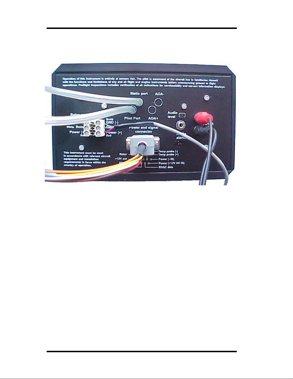
MGL Avionics Stratomaster Ultra Horizon XL Owner’s manual
Connections to the Ultra
Power to the Ultra
The Stratomaster Ultra requires between about 7.0V to 28V of DC power supply. Current
consumption i s ve ry low at about 40 mA without display backlighting and in the region of 80 mA
with backlight. These figures are for a supply voltage of 13.8V DC.
Generally it i s n ot required to fit any form of pow er supply filters or surge sup pressors as the
Stratomaster Ultra include s the required protection devices. External power line filters or surge
protectors should only be considered in ver y u nusual conditi ons.
Important note: Please provide the Stratomaster with its own ground (earth) return wire to
the battery. Do not share t his wire with an y ot her equipment like lamps, radios or any
other items. Spurious currents caused by other equipment can cause t he Stratomaster to
receive an in valid ground reference.
Please note: If you set the display backlight mod e to “auto”, the display backlight will be switched
off automatically after four minutes of no activity to conserve power. The display backlight will
remain switched on if engine revs are detected.
You can select backlight modes in the Device Setup Menu under Basic operation Setup.
If you are using the standard co nnector supplied with your Ultra, power needs to be connected to
the Red and Black wires. Red is positive +12VDC and black should be connected to the battery
minus. Do NOT reverse these connections.
If you are using your own connector, please connect as indic ated on the rear p anel.
Page 69
Page 70

MGL Avionics Stratomaster Ultra Horizon XL Owner’s manual
Ambient temperature sender
The Stratomaster Flight includes a precision semiconductor temperature probe. It is
recommended that you install it as shown above. The RED wire connects to the “Temp pro be +”
terminal. The remaining w ire is GREEN. This wire connects to t he “Temp probe –“ terminal.
If you are using t he supplied cable connection, wire the RED wire of the probe to the Orange wire
of the connector. The green wire from the probe connects to the green wire of the connector.
The probe head itself should be mounted using suitable means outside of the instrument pod or
aircraft if a closed cockpit aircraft is used. The probe should be placed in the shadow of the pod
or aircraft or in a place were sunlight cannot heat the probe. Also ensure that engine heat or
exhaust gases cannot heat the probe at any time. Remember – the probe is intended to show the
temperature outside
The twisted cable can be extended should this be required. In this case please use a similar
cable type and continue the twist for the length of the cable.
The probe is requ ired for the display of ambient temperature and density altitude.
We recommend that you install the external temperature probe.
Should you require a suitab le rep lac em ent probe , it can be obt ained fr om MG L Av ionics at
reasonable cost or you can make up your own probe. In this case please obtain a National
Semiconductor Te mperature Sensor type LM 335 in a TO92 pack ag e.
External, visual alarm indicat or
If you are using the supplied connector, the alarm output is on the white wire.
The alarm output is a open collector transistor switching to ground (batter y minus) in case of an
active alarm.
You can use this to switch a alarm lamp or LED. In case of a LED you need to wire a series
resistor in line with the LED to provide current limiting. Consult your LED data sheet for required
values.
The white wire should be connected to one pole of the lamp or the cathode of the LED. The
remaining pole of the lamp should be connected to +12VDC.
The anode of the LED should be wired to the dropping resistor. The remaining connection of the
dropping resist or should be wire d to +12VDC.
Typical values for the dropping resistor are 100 to 500 ohms depending on the amount of current
the LED can handle.
In case of a lamp, d o not use a lamp with a greater power rating than 6W at 12 volts.
Maximum current for the alarm line is specified at 0.5A.
of your aircraft – not inside.
Page 70
Page 71
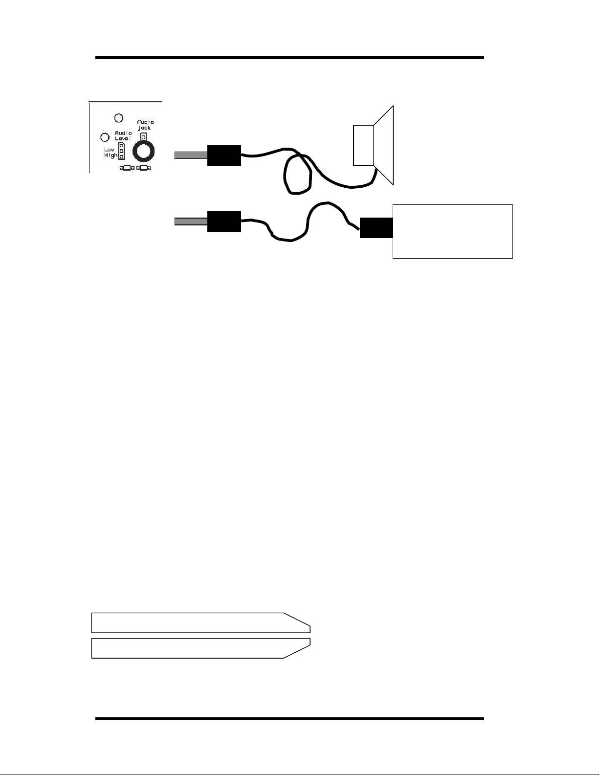
MGL Avionics Stratomaster Ultra Horizon XL Owner’s manual
External, audible alarm
4 or 8 Ohm speaker
mounted in panel or
suitable location
Intercom syst em with
external audi o input
(music input or similar)
In addition to the alarm output contact described in the previous section, you can connect either a
speaker or an in tercom system t o the Stratomaster Ultra. In this case an alarm tone will sou nd
once a second for ha lf a second whene ver an alarm is active.
In case you connect a speaker, the audio level link should be left open.
Should you want to connect to an in tercom system that has an exter nal audi o input, close the
audio level link.
Note: Please ensure that your interc om s ystem will mut e any extern al aud io should ra dio
transmissions be received. It may be illegal in your country to use any other system.
Pitot tube and static port
Pitot tubes are found in a large variety in at your aircraft parts shop, in mail order catalogs or you
can make your own.
Contrary to popul ar belief, Pitot tubes are not carefully designed and c alibrated but are simple
orifices or tubes that get point ed in the direction that you are flying. The forward movement of the
aircraft cause s a ir to dam inside the pitot tube. This increases the pressure inside the t ube. The
Stratomaster Flight contain s a se nsitive silicon diaphragm sensor that measures t he pr essure
difference between the pitot pressure port and the static port. This measur em ent is used to
calculate the ai rsp eed .
In addition, the static port is connected to the altimeter sensor.
Most small aircr aft such as ultralights or microlights do not require a connection to a static port. In
these cases, simply leave the stat ic port ope n. En sure how e ver that the stati c port does not
receive pressurize d air due to the forward movement of the aircraft.
Static ports are usually mounted at a strategic position on the r ear side of the aircraft fuselage for
faster, pressurized aircraft.
Suitable pitot tubes can be made from a short piece of hollow aluminium or copper piping. Lengt h
and diameter ar e not importan t. Ensure that the front of the pitot tube has a suitable chamfer if
you use thick walled tubing or you may introduce a speed reading error if you have a faster
aircraft.
Example cross-section of thick walle d pitot tube.
Page 71
Page 72

MGL Avionics Stratomaster Ultra Horizon XL Owner’s manual
Pitot and static port (Continued from last page)
Suitable connection hose for both pitot tube and static port can be obtained from a har dware
store or even a pet shop. Good quality tubing is often used for fish tanks and it has just the right
diameter.
Please note that this kind of tubing is not advised for pressurized aircraft. In this case you would
need to obtain aircraft grade tubing of suitab le diameter. You would also have to use hose
clamps to fasten the hose onto the Stratomaster pitot and stat ic ports.
The Stratomaster Ultra instrument allows you to calibrate the airspeed reading. This is done in
the “Device setup M enu ” “ASI Gain”. Th e main reason for this is to be able to remove erro rs
introduced due to the airflow around your aircraft which may have an eff ect of your pitot tube
pressure build up.
If you have a GPS r eceiver with a ground speed function you can use this as reference after
allowing for an y w inds (Choose a wind still, absolutely calm day if possible).
You should also com pensate for dens ity altitude before you correct the ASI reading. I t is quite
normal to under-rea d on the ASI if your are flying at higher than sea level in mo der a te or hig h
temperature s. You can set the Stratomaster Ultra instrument to display “True airspeed” or TAS. In
this case a correction factor depending on your current altitude is applied.
Zeroing the air-s peed sensor.
It may be required from time to time to zero the airspeed and VSI readings. This will be true if you
are reading a small VSI or ASI when the aircraft is st anding still on the ground.
Ensure that the readings are not caused by winds or other factors before performing the zero
calibration. Also, ensure that no wind is blowing into the pitot tube.
The zero calibration is outlined in the owners m anual. It is quick and easy and will ensure that
your Stratomaster Ultra will perform at it s best at all times.
Page 72
Page 73

MGL Avionics Stratomaster Ultra Horizon XL Owner’s manual
Getting started with the Ultra
So, you have installed your Stratomaster Ultra. What now ?
Here is a short list of things you should do to make the instrument work the way you want it.
1) Verify that the RDAC is connected and w orking. The red LED on the RDAC sh ould be
flashing. You should see EGT and CHT readings giving approximate ambient
temperatures (if the engine has not been running).
2) Altitude OK ? Good. Adju st the QNH using the + and – keys so you get your fields corr ect
elevation.
3) Pilot tube connecte d and poi nti ng the direction you think your ai rcr aft is going to fly ?
Blow lightly into the pi tot tube and verify that you get an airsp ee d readi n g. Get some body
to do it for you if required.
4) Now go to th e “Mode and units setup menu” (You ’ll find it in the “D evice setup me nu” ).
Select your required units of measure. Also, at this ti me select three important items
listed here:
How do you want to log flights ? Set to automatic or manual detect of flight st art and end.
5) Have you got your fuel level sender(s) installed and connected ? Perhaps now is the time
to calibrate your sender(s) as detailed in the relevant chapter in this manual.
6) Start the engine. Do you get correc t RP M indication and is the RPM stable ove r the full
range ? Adjust Rev counter cali bration if requ ir ed.
7) Select your engine type using the “Engine quick type selec t” , per h aps select an engine
closest to what you have and then modify the entries in the “Engine detail setup” so you
have the temperature ranges and alarm levels the way your n eed them.
8) Select from t he choices available how you want to use the twelve TC channels. You do
this in the “Engine detail setup menu”.
9) Connect your SP-1, SP-2 or SP-3 se nsor package. Verify that your AHRS indicator is
functional. You will have to perfo rm compass swing (de v iation compensation) and setup
various factors for your horizon to perform as expected. Please view the documentation
that comes with your sensor package for the required procedures.
Finally, verify that all your conne c ted probes and senders operate the way they should. Ar e all the
readings correct and as expected ?
Is all wiring secure ? No loose cables ? Have you made sure that the RDAC unit has a nice and
SHORT electrical connection between the ground terminal and the engine block ? This
connection must not br ea k due to engin e vibrations.
Everything done and work ing ?
Congratulations – you have one of the finest instruments on Earth in your aircraft.
Best wishes from the team at MGL Avionics.
Page 73
 Loading...