

Page 1
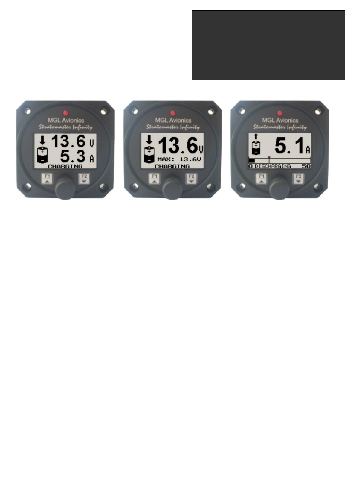
BAT-1
Battery voltage and current monitor
Operating Manual – English 1.03
Introduction
The BAT-1 is a 2.25” instrument used to monitor your aircraft’s battery power supply. It can be used on lead-acid, NiCad
batteries as well as gel cells. This instrument is very useful in determining your battery’s health, charging status, as well
as the current load consumption of your aircraft. The BAT-1 can be used in both 12V and 24V aircraft and can measure
voltages up to 30V DC.
The BAT-1 uses standard current shunts and is able to measure currents in the range of 5A to 500A.The instrument
contains a programmable low/high voltage alarm to automatically detect bad batteries and alternator failures.
1 Features
• Measure voltage and current simultaneously
• Can measure voltages up to 30V (compatible with both 12V and 24V aircraft supplies)
• Contains a programmable low/high voltage alarm to automatically detect alternator failures and bad batteries
• Includes a battery charge/discharge indication
• Choice of 3 display modes (volts only, current only, or dual current and voltage display)
• Records maximum volts, charge and discharge currents in permanent memory
• Analog bar graph indicating charge/discharge current
• Multi-language support
• Standard 2.25” aircraft enclosure (can be front or rear mounted)
• Rotary control plus 2 independent buttons for easy menu navigation and user input
• Alarm output as well as a red LED that illuminates when the alarm has been activated
• Large backlit graphic LCD with adjustable contrast
• On board voltage reversal and over voltage protection for harsh electrical environments
• SMPS (switch mode power supply) for use in both 12V and 24V systems as well as for reduced power
consumption
• Light weight design
• 1 year limited warranty
Page 2
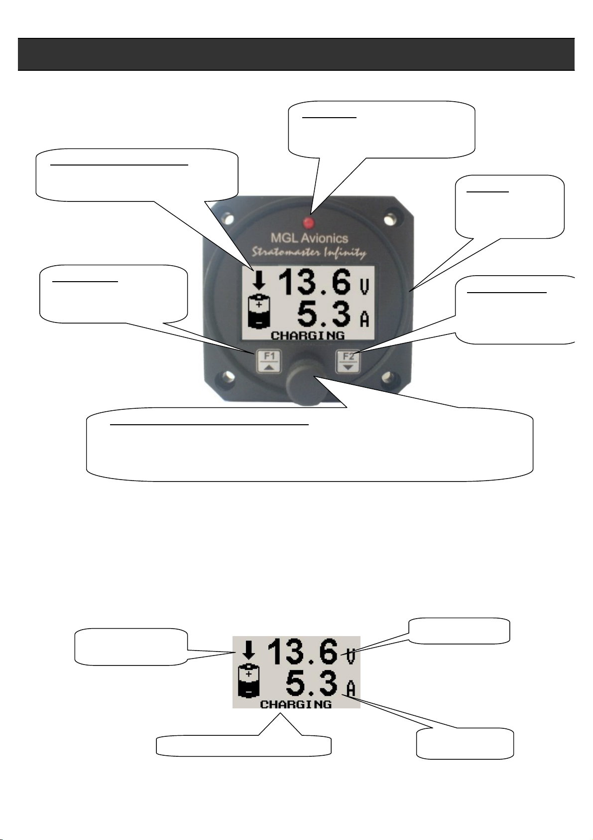
B
acklit Graphic
LCD
Display:
Harness:
Up/F1 Button:
Down/
F2 Button
:
normal mode
Rotary Control (Up/Down) & Enter Button
:
Press the rotary control during normal mode to access the menu system. Rotate
setup to
LED Alarm:
exceeded
BAT-1 Operating Manual Page 2
2 BAT-1 Layout
Contrast and backlight can be adjusted
in the menu system
Up button in menu system
Maximum values display in
normal mode
The red LED will illuminate if the
voltage alarm set-point has been
Harness connects
to power and the
current shunt
Down button in menu
system
Contrast adjustment in
anti/clockwise for up/down menu scrolling. During normal mode the BAT-1 can be
display either the voltage or current display, then by rotating the rotary control the display
will toggle between the voltage and current displays.
3 Main Display
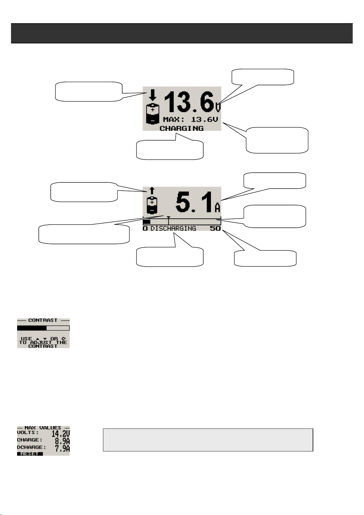
There are 3 main displays that can be setup to be displayed on the BAT-1: dual mode (current and voltage), voltage
display only or current display only. The unit can be setup to toggle manually or automatically between voltage and
current in the single value display modes.
Dual Mode
Charge/Discharge
icon
Charge/Discharge indication
Voltage display
Current display
Page 3
Note:
The
permanent
maximum values are stored in non
-
volatile
icon
indication
indicator
indication
icon
BAT-1 Operating Manual Page 3
Voltage Only
Charge/Discharge
Current Only
Charge/Discharge
Maximum current reached
Voltage display
Maximum voltage
reached
Charge/Discharge
Current display
Current analog
bar graph
Charge/Discharge
Current span
3.1 Contrast Display
This display can be accessed by pressing the F2 key during the normal display mode. This is a quick access key to the
same contrast menu in the menu system.
Select this menu option to adjust the display contrast
3.2 Maximum Values Display
This display can be accessed by pressing the F1 key during normal operation. Pressing the F1 key again will reset the
maximum values to the current voltage and current values. Pressing any other key will cause the BAT-1 to return to the
normal display mode. To avoid false recordings, the maximum values function is only activated 10 seconds after the
instrument has powered up.
memory and are recalled on power-up.
Page 4
Note:
(ADC Values and Calibrate Menus are only visible when powering up the unit and pressing the
. Changing any values in this menu may
to
BAT-1 Operating Manual Page 4
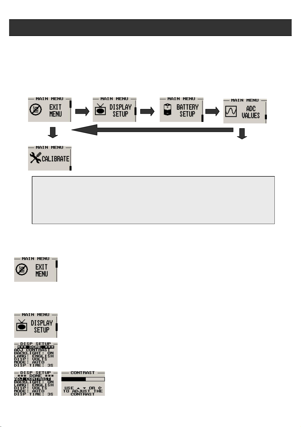
4 Menu System
Pressing the rotary control button during the normal display mode will cause the BAT-1 to enter the menu system. Use
the up/down keys or the rotary control to navigate through the menu system. If no key is pressed within 30 seconds, the
BAT-1 will return to the normal display mode.
Rotary Control). The text “CALIBRATE” will appear on the intro screen when entering this mode.
Warning: The Calibrate Menu is for technical personnel only
cause the instrument to display incorrect information, and may require the instrument to be returned
the factory for recalibration.
4.1 Exit Menu
Pressing the rotary control on this menu item will cause the BAT-1 to exit the menu system. All
changes made during navigation of the menu system will be saved in non-volatile memory on exiting
the menu system. If you remove power before exiting the menu the instrument will not save any
changes.
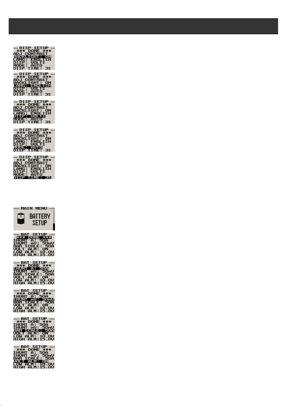
4.2 Display Setup
Move the highlight over the “DONE” menu item and press the rotary button to return to the main
menu
Select this menu option to adjust the display contrast
Page 5
BAT-1 Operating Manual Page 5
Select this menu option to turn the backlight on and off
Select your preferred language for the BAT-1.
Select the display mode of the main display: dual mode, voltage only or current only
Select whether you want the single voltage/current display to alternate automatically or manually
This display is only shown if display mode is setup to show either voltage only or current only
Set the time that the single display modes must be displayed for. This display is only shown if auto is
selected for the display mode
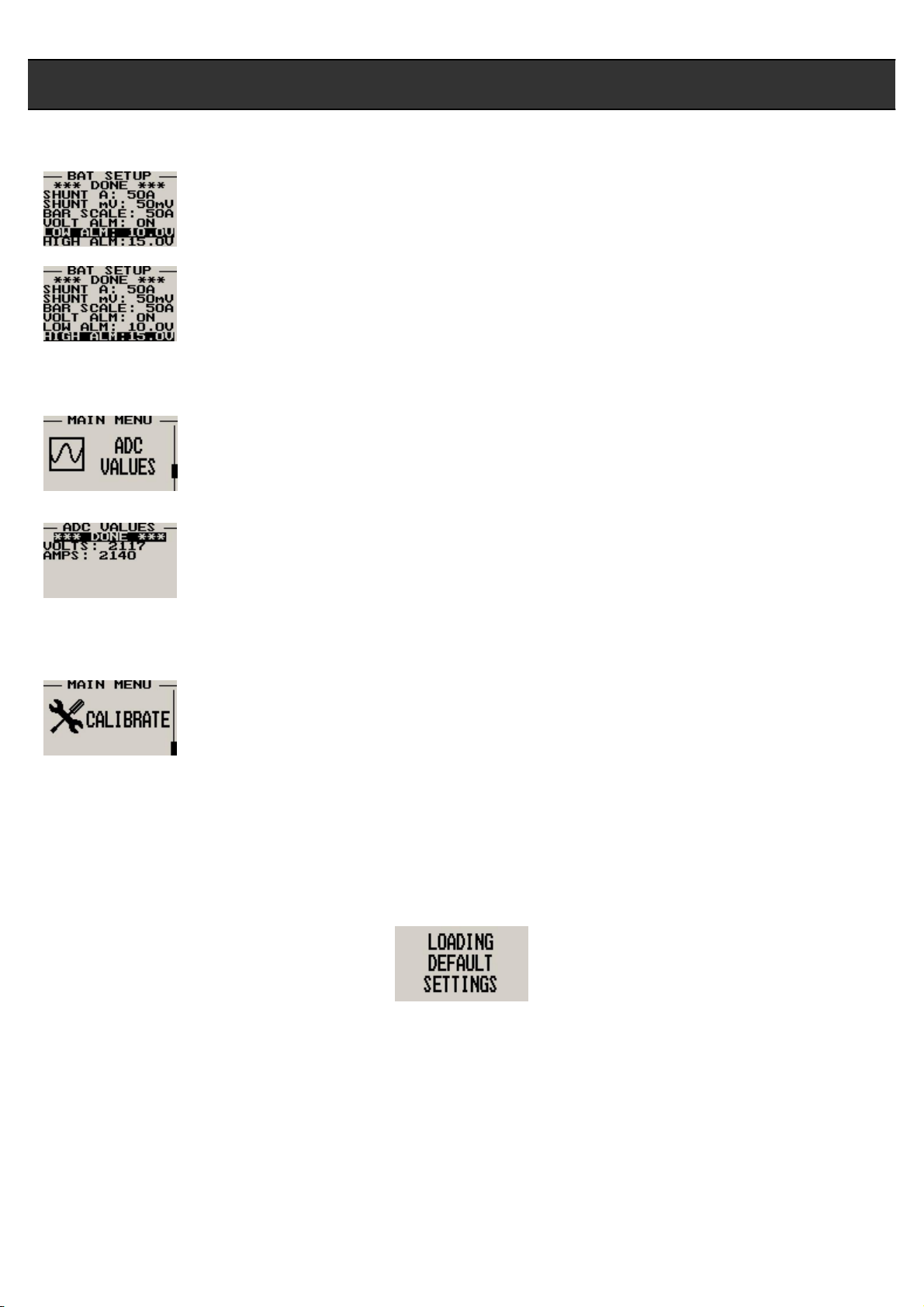
4.3 Battery Setup
All the battery voltage and shunt parameters can be setup here
Move the highlight over the “DONE” menu item and press the rotary button to return to the main
menu
Select the current capacity of your current shunt. The BAT-1 can use current shunts in the range of
5A to 500A.
Select the mV rating of your current shunt. Current shunts in the range from 50mV to 100mV can be
used.
Select the maximum value that you want the current analog bar graph display to show, i.e. your
current shunt may be a 50A 50mV shunt but the maximum current that you will ever measure is only
7A, then you can scale the bar graph to show a maximum value of 10A. This gives you increased
display resolution
Select whether you want the voltage alarm to be turned on or off. To avoid false activation of the
alarms, the alarm function is only activated 10 seconds after the instrument has powered up
Page 6
BAT-1 Operating Manual Page 6
Enter the low voltage set-point for when the alarm must be activated. Any voltage below this value
will activate the alarm
Enter the high voltage set-point for when the alarm must be activated. Any voltage above this value
will activate the alarm
4.4 ADC Values
Note: This menu item is for technical personnel only, and is not displayed during the normal
operation of the instrument. Please see section 4 above on how to access this menu item
This menu displays the ADC values that have been read from the voltage and current circuits
4.5 Calibrate
Note: This menu item is for technical personnel only, and is not displayed during the normal
operation of the instrument. Please see section 4 above on how to access this menu item. Consult
your local dealer or factory before entering this menu.
5 Loading Factory default settings
Pressing and holding the F1 and F2 keys simultaneously on power up will cause the BAT-1 to load preprogrammed
factory default settings. The following screen will be displayed:
6 Operating the alarms
If the alarm is activated, the corresponding item on the display will flash. At the same time the externally available alarm
switch will close. The switch will remain closed until any button is pressed to acknowledge the alarm or until the
condition(s) that activated the alarm no longer exist. The alarm output can be used to switch an external alarm indicator.
The external alarm switch is an open collector transistor switch to ground with a maximum rating of 0.5A DC. It is possible
to wire the alarm contacts of several Stratomaster Infinity instruments in parallel should this be desired. To avoid false
activation of the alarms, the alarm function is only active 10 seconds after the instrument has powered up.
Page 7

Warning:
he unit is exposed to
BAT-1 Operating Manual Page 7
7 Shunt selection
The BAT-1 can use a current shunt in the range from 5A to 500A, 50mV to 100mV. Please note that the current shunt
rating can effect resolution and accuracy of the BAT-1. Select a current shunt that is right for your application. Try use a
current shunt that is close to the current range you are measuring.
The BAT-1 measures current by measuring the voltage drop across the current shunt. The BAT-1 is calibrated for +100mV. Try to use a current shunt mV rating close to this value to increase the measurement resolution. The BAT-1 has a
resolution of 0.1A up to 10A and 1A from 10A to 500A. If the current shunt selected is above 100A then the resolution is
fixed at 1A. The BAT-1 has an over range warning if you exceed the current rating of the shunt by +-10%.
8 Cleaning
The unit should not be cleaned with any abrasive substances. The screen is very sensitive to certain cleaning materials
and should only be cleaned using a clean, damp cloth.
water and/or spray jets.
The BAT-1 is not waterproof. Serious damage could occur if t
9 BAT-1 Specifications
Operating Temperature Range
Storage Temperature Range
Humidity
Power Supply
Current Consumption
Display
ADC
Dimensions
Enclosure
Weight
Alarm contact current rating
Non-volatile memory storage
Current shunts supported
Current resolution
Voltage resolution
-10ºC to 50ºC (14ºF to 122ºF)
-20ºC to 80ºC (-4ºF to 176ºF)
<85% non-condensing
8 to 30Vdc SMPS (switch mode power supply) with built in 33V over voltage
and reverse voltage protection
Approx. 30mA @ 13.8V (backlight on) 15mA @13.8V (backlight off)
114x64 graphics LCD display. Contrast and backlight is user configurable,
green/yellow backlight
12bit over sampled successive approximation
60mmx60mmx61mm (2.36”x2.36”x2.40”) (see Infinity series dimensional
drawing)
2.25” ABS, black in color, front or rear mounting
Approx. 85 grams
Open collector transistor switch to ground. Maximum rating 0.5A DC
100000 write cycles
50mV to 100mV, 5A to 500A
0.1A from 0 to +-10A (Current shunt<=100A), 1A above 10A
0.1V
10 Installation
Make sure that the starter motor does not go through the shunt resistor. This will cause excessive current to be drawn
and can result in damage to the shunt. Also check that the cable from the alternator is going through the shunt, so that
charging current can be measured.
Page 8
BAT-1 Operating Manual Page 8
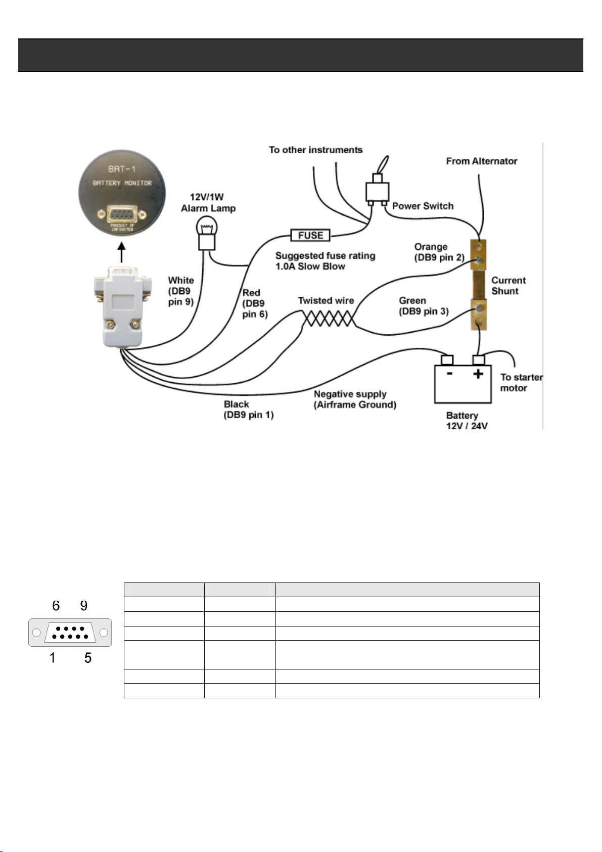
10.1 Connection Diagram
The use of an external 1A fuse is recommended. Connect the supply terminals to your aircrafts power supply. The BAT-1
can be used on both 12V and 24V without the use of any pre-regulators. Ensure that the supply voltage will not drop
below 8V during operation as this may result in incorrect voltage and/or current readings.
10.2 BAT-1 DB9 Cable connections
DB 9 Pin Color Function
1 Black Ground
2 Orange Shunt 3 Green Shunt +
4 NC Airtalk communication (Not connected)
6 Red 8-30Vdc power
9 White Alarm Output
Used for firmware upgrading
Page 9

Note:
BAT-1 Operating Manual Page 9
11 Warranty
This product carries a warranty for a period of one year from date of purchase against faulty workmanship or defective
materials, provided there is no evidence that the unit has been mishandled or misused. Warranty is limited to the
replacement of faulty components and includes the cost of labour. Shipping costs are for the account of the purchaser.
Product warranty excludes damages caused by unprotected, unsuitable or incorrectly wired
electrical supplies and/or sensors, and damage caused by inductive loads.
12 Disclaimer
Operation of this instrument is the sole responsibility of the purchaser of the unit. The user must make themselves familiar
with the operation of this instrument and the effect of any possible failure or malfunction.
This instrument is not certified by the FAA. Fitting of this instrument to certified aircraft is subject to the rules and
conditions pertaining to such in your country. Please check with your local aviation authorities if in doubt. This instrument
is intended for ultralight, microlight, homebuilt and experimental aircraft. Operation of this instrument is the sole
responsibility of the pilot in command (PIC) of the aircraft. This person must be proficient and carry a valid and relevant
pilot’s license. This person has to make themselves familiar with the operation of this instrument and the effect of any
possible failure or malfunction. Under no circumstances does the manufacturer condone usage of this instrument for IFR
flights.
The manufacturer reserves the right to alter any specification without notice.
Other instruments in the Stratomaster Infinity series
ALT-1 Precision encoding altimeter and vertical speed indicator
ASI-1 Airspeed indicator (ASI) with automatic flight log
ASX-1 Encoding aviation altimeter with serial output and airspeed indicator (ASI)
AV-1 Artificial horizon and magnetic compass indicator
BAT-1 Battery voltage and current monitor
E-3 Universal engine monitor
FF-1 Fuel computer (single or dual fuel tanks)
GF-1 +-10G tilt compensated dual range G-force meter
MAP-1 Universal pressure indicator
RV-1 Universal engine RPM and rotor RPM Indicator
RTC-2 Aviation real time clock (RTC) and outside air temperature (OAT) display
TC-1 4-Channel thermocouple indicator
TP-1 Universal temperature and pressure gauge
 Loading...