

Page 1

Stratomaster Maxi Single
ALT-3, ALT-4, ALT-5
ALT-3: Wide range precision aviation altimeter
ALT-4: Encoding altimeter with Gillman code transponder output
ALT-5: Encoding altimeter with serial output, compatible with
IIMorrow, Garmin/Trimble or MGL RS232 protocols.
The ALT-3 altimeter is a 3.5” instrument that can be used as absolute or relative altimeter.
In addition, it offers a wide range VSI (vertical speed) indicator as standard option.
ALT-4 and ALT-5 models include a gillman code and serial transponder interface.
The altimeter conforms to ANSI standard atmosphere rules from –700 ft up to a minimum of
40.000 ft. Accuracy is ensured by thermal compensation of the laser trimmed pressure sensor.
High resolution is made possible by stable and sensitive electronics.
The altimeter can display altitude in feet or meters, local pressure can be set in millibars or inches
or mercury.
Page 2
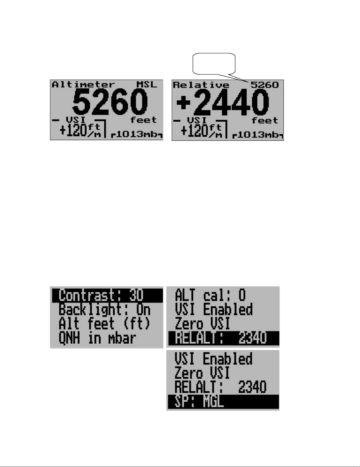
Absolute mode / Relative mode
Absolute mode: Altitude relative to sea level (MSL)
Relative mode: Altitude relative to some other altitude
Switching between absolute and relative modes is done using the “Enter” key when you see the
main screen.
As you switch from absolute to relative mode you can set the current altitude as the new
reference altitude. You do this by holding the “Enter” key down for two seconds as you switch
from absolute to relative mode.
Alternatively, you can set the reference altitude in the menu. This you would do if you need to set
a reference that is not obtainable through your current flight profile.
Reference
altitude
Setting up the ALT-2,3,4
Press the Menu key to enter the menu. You can move forward and backwards in the menu by
using the + and – keys. To change or select a menu item, move the highlight to the desired item
and then press the Select (Enter) key. To end an edit or function, press the Menu key again.
The Menu functions listed in the following section is based on the ALT-5. For ALT-3 and ALT-4
variants, ignore the serial protocol settings.
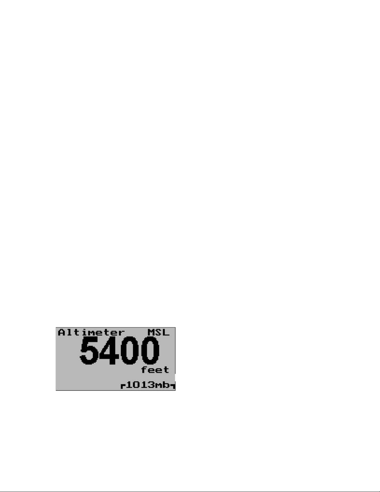
These images show the available menu
functions. Note that the “SP:” function is
available in the ALT-5 only.
Page 3
Contrast …
This function allows you to change the display contrast to your liking. You can select values from
about 20 to 45. (can vary depending on display type).
Backlight …
This function allows you to switch the display backlight on or off.
The backlight is normally left on. Should you need to reduce current consumption of the
instrument for special applications you can switch the backlight off.
ALT
Select if you want your altitude readout in feet (ft) or meters (m).
QNH
Select if you want your local pressure readout in millibars (mB) or inches or mercury (“HgA).
ALT cal
This is a technical function that is used to calibrate your altimeter to an exact reference. On the
back of your altimeter you will find the calibration number that has been determined to result in
the most accurate reading of your altimeter. This is the value that should be entered here. Should
you have access to an accurate reference you may use this function to calibrate your altimeter.
Before you do this, ensure that you have your local pressure set to coincide with a calibrated and
certified reference.
Your altimeter has been calibrated by the factory to an accuracy of +/- one mB or approximately
+/- 30 ft (10m).
VSI
Select if you want to show the built in VSI (vertical speed indicator). The built in VSI will be shown
just above the altitude readout. VSI will be displayed in feet/minute or m/s depending on your unit
selection.
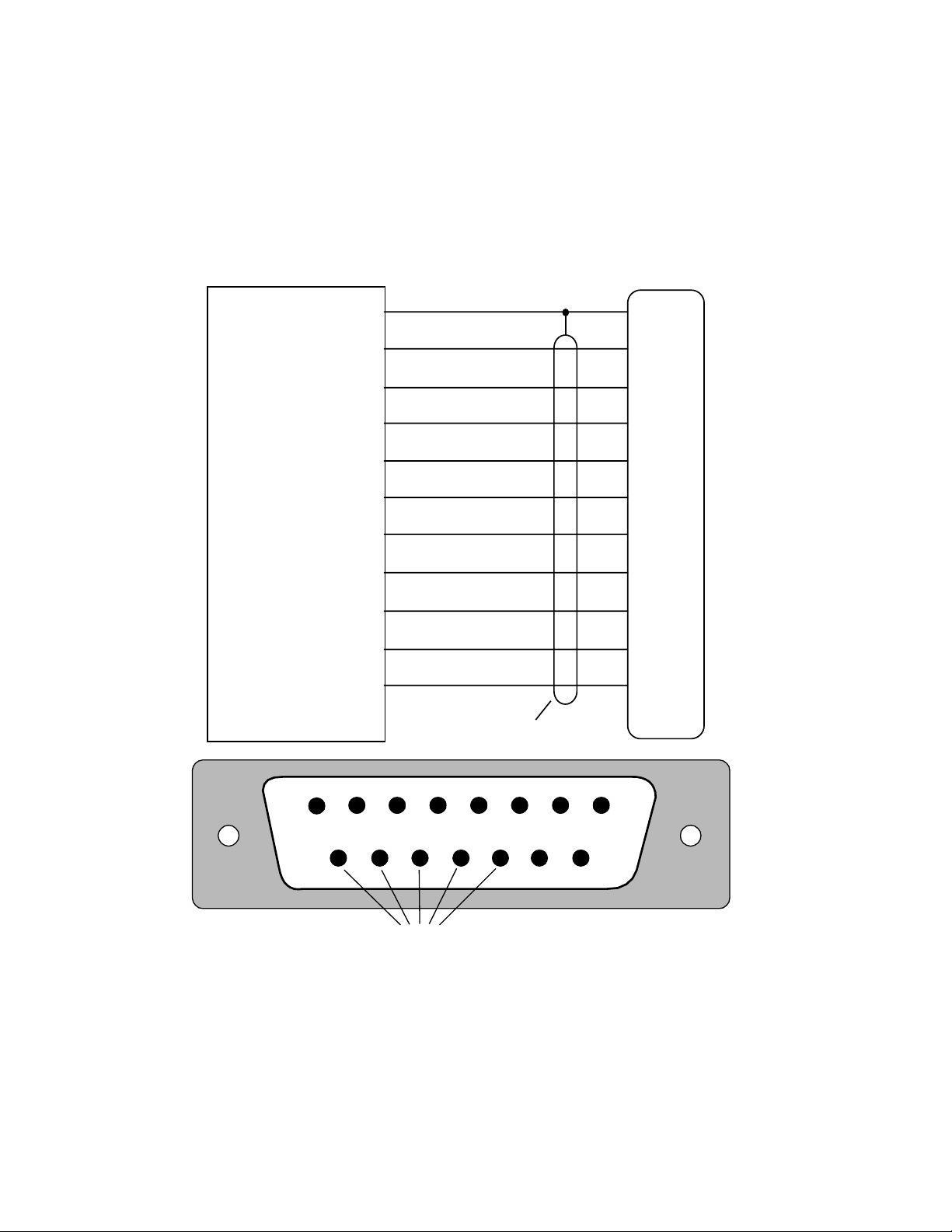
Main display showing VSI readout disabled
Zero VSI
This function is used to set your VSI to read exactly 0ft/min. This is similar to setting the needle
on a mechanical VSI to point to zero by turning the adjustment knob on such a VSI.
Page 4

The electronic VSI generally has much less drift compared to a mechanical VSI and this function
will only be used very occasionally. Ensure that you perform this function when no pressure
changes due to wind or other reasons are occuring.
It is normal for the VSI to show short, small positive or negative readings when your aircraft is
standing still on the ground. The digital VSI is very sensitive and will show very small changes in
pressure.
SP …
Select the protocol you would like to use for the serial output. Please see the following protocol
section for available protocols and their exact definition. You must select the correct protocol for
the device connected. Note that only the ALT-5 supports serial protocols.
IIMorrow serial protocol
The IIMorrow protocol uses RS232, 1200 baud, 8 data bits, one stop bit, no parity.
Message transmission rate is once per second.
Example altitude message for 10500 ft:
#AL +10500T+25D7cr
The message consists of #AL followed by a space.
This is followed by a “+”, then five digits for the altitude in feet relative to 1013mB local pressure
setting. The altitude is padded with leading zeros if required to make up five digits.
This is followed by the letter “T” , a “+”, the two digits “25” and a single byte checksum over all the
characters in the message up to and excluding the checksum. The checksum is a simple modulo
256 sum of the binary values of the individual characters. The checksum is sent as two
characters in hexadecimal format. The message ends with a carriage return (0x13).
Negative altitudes are transmitted as 00000. Altitudes are transmitted in feet.
Trimble/Garmin protocol
The Trimble/Garmin protocol uses RS232, 9600 baud, 8 data bits, one stop bit, no parity.
Message transmission rate is once per second.
Example altitude message for 10500 ft:
ALT 10500cr
The message consists of the three letter “ALT” followed by a space. This is followed by a five digit
altitude relative to a local pressure setting of 1013mB. The altitude is padded with leading zeroes
if required to make up five digits. Finally the message is terminated with a carriage return (0x13).
Negative altitudes are transmitted as 00000. Altitudes are transmitted in feet.
MGL protocol
The MGL protocol uses RS232, 9600 baud, 8 data bits, one stop bit, no parity.
Message transmission rate is once per second.
Example altitude message for 10500 ft:
Page 5

ALT+10500C+10500L1013+0000XBAcr
The message starts with “ALT” followed by six characters altitude. The first character is either a
“+” or “-“ if the altitude is negative. This altitude is relative to a local pressure of 1013mB.
This is followed by the character “C” and a further six character altitude. This altitude is corrected
for the current local pressure setting of the instrument. Note that it is possible for the first altitude
to be positive and the second altitude to be negative or vice versa.
This is then followed by the character “L” and a four digit local pressure setting in millibars (mB).
Finally, a five character field shows the current positive or negative VSI reading in ft/min.
This is followed by the character “X” and a two byte checksum in hexadecimal format. Please see
the IIMorrow protocol for checksum details.
The final character is a carriage return (0x13).
Altitudes are transmitted in feet.
Page 6
Connecting the Gillman code transponder interface (ALT-4 only)
The connection to the transponder consists of 10 or 11 connections, many transponders accept
only codes A1 to C4, in this case you will leave signal D4 unconnected. This example shows the
required connection to a Microair T2000 transponder. Other transponders are similar.
View of the encoder output connector of the ALT-4 from behind the instrument. Pin 1 of the D15
connector is on the upper right hand corner (signal A1).
Microair T2000
Transponder
Ground
A1
A2
A4
B1
B2
B4
C1
C2
C4
D4
3
9
10
11
12
13
17
18
19
20
21
B4 B2 B1C1C2
Ground
Use shielded wire
A4 A2 A1
C4
D4
ALT-4 D-15
connector
15
Ground
1
A1
2
A2
3
A4
4
B1
5
B2
6
B3
7
C1
8
C2
9
C3
10
D4
Page 7

Should you use the included D15 connector harness the layout of the signals on the grey ribbon
cable is as follows:
A1 This signal is on the cable with the red marker band
C4
A2
D4
A4
Ground
B1
Ground
B2
Ground
B4
Ground
C1
Ground
C2
The ALT-4 altimeter will measure altitudes typically to around 42000 ft, however, this requires a
transponder that uses signal D4. Transponders that do not have D4 can only transmit altitudes up
to 35000 ft.
The ALT-4 produces inverted Gillman codes as required by virtually all transponders. The outputs
are open collector types and will sink currents up to 0.5A but this is not recommended in praxis.
Typical sink currents with transponders are only a few mA at the most.
It is recommended to use shielded cable for the connection between encoding altimeter and the
transponder if a long cable needs to be used. The shield should be connected to ground at one
point only (either on the encoding altimeter side or on the transponder side).
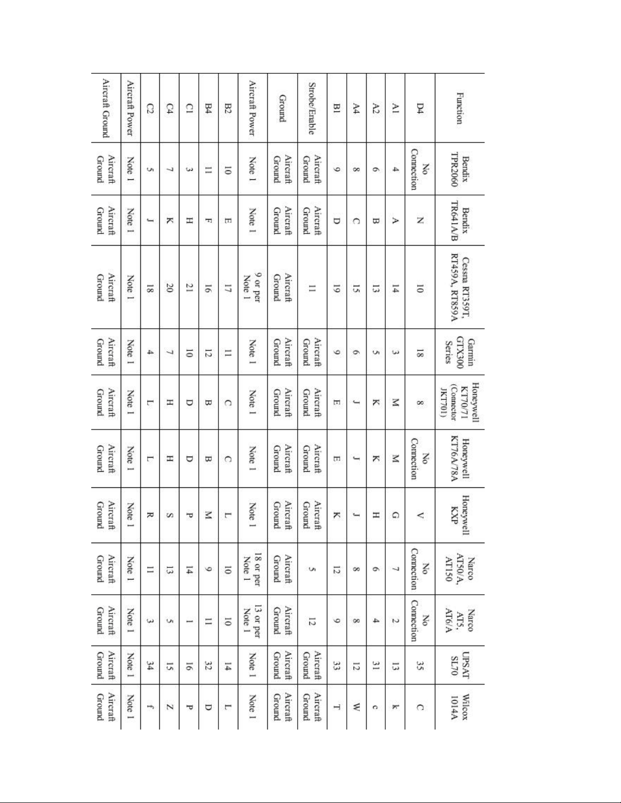
Following is a table of commonly used transponders and their Gillman code connections.
Please consult your transponders installation manual on the physical position of every contact.
Ensure that you wire the Gillman codes correctly and securely.
Installation of the wiring requires solder work. This needs to be done using electronic resin flux
solder wire and proper temperature controlled soldering stations. Do not attempt this if you are
unfamiliar with electronic soldering techniques. Please get professional assistance to do this. Bad
connections can result in your transponder broadcasting incorrect altitude codes.
Page 8
Page 9

Technical specifications:
Display temperature range (operational): -20 to +80 degrees C
Supply voltage: +8 to +18V. +24/28V with optional pre regulator.
Supply current: 35mA/70mA (backlight off/on)
Altimeter range: -700ft to 40.000ft (45.000ft typical, not guaranteed)
Altimeter resolution: 10ft at sea level.
Measurement accuracy: +/- 1mB, +/- 30ft at sea level.
VSI range: +/-10.000ft/min, dead band 20ft/min, resolution 10ft/min.
Serial port: RS232, transmit only, RCA connector.
Gillman code port: Open collector darlington drivers.
Weight: 180-200 grams depending on type.
Warranty:
MGL avionics warrants their products for a period of one year from date of purchase against
faulty workmanship. Warranty is limited to the replacement of faulty components and includes the
cost of labor. Shipping costs are for the account of the purchaser.
Note for operation on supplies with inductive loads:
Any operation of electronic instrumentation on power supplies that are subject to high voltages
caused by operation of inductive loads (starter motors, solenoids, relays) are required to be fitted
with suitable protection.
All Smart Singles are guaranteed to withstand temporary over voltage up to 40V without
additional protection. We recommend that measures are taken to prevent voltage transients in
excess of this limit.
MGL Avionics recommends the fitment of a fuse in line with a 33V transorb (available from MGL
Avionics at low cost) to protect electronic instruments, radios and intercom systems. Only one
such arrangement is required for a cluster of instruments.
Please note that product warranty excludes damages caused by unprotected, unsuitable or
incorrectly wired electrical supplies.
This instrument is not certified by the FAA. Fitting of this instrument to certified aircraft is subject
to the rules and conditions pertaining to such in your country. Please check with your local
aviation authorities if in doubt.
This instrument is intended for ultralight, microlight, homebuilt and experimental aircraft.
Operation of this instrument is the sole responsibility of the pilot in command (PIC) of the aircraft.
This person must be proficient and carry a valid and relevant pilots license. This person has to
make him/herself familiar with the operation of this instrument and the effect of any possible
failure or malfunction. Under no circumstances does the manufacturer condone usage of this
instrument for IFR flights.
Important information:
Depending on laws and regulations in your country you may not be allowed to install a
transponder and associated equipment yourself. This work may have to be done by a certified
AMO or instrument technician.
Please check with your relevant authorities.
Page 10

The ALT-4 encoding altimeter is uncertified equipment and may normally only be used in
uncertified aircraft, homebuilt aircraft and microlights (ultralights). Special operations permits for
other aircraft may be required.
Please be very aware that any wiring mistake related to the application of Gillman codes to your
transponder will result in incorrect altitudes broadcast by your transponder.
Any installation involving the CNV-ALT2 must be checked by a suitably equipped aircraft
instrument maintenance outfit before operation. Failure to do this may be a criminal offence in
your country.
Attention:
Your country may have regulations that do not allow you to install a transponder or an
encoding altimeter yourself. The installation may have to be performed by an authorized
person or company. Please check your applicable regulations with your aviation
authorities.
Page 11
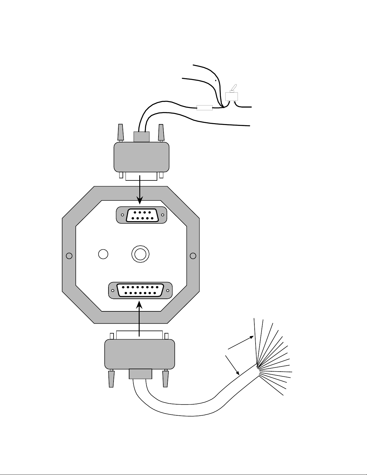
Installing the ALT-3, 4 or 5 altimeter
To other instruments
Connect static port
to suitable static line
on aircraft.
Note: leaving this port
unconnected may lead to
altitude errors as cabin
pressure chages due to
airflow or other factors
Static port
Cannon D-9
connector
RS232
RED
Fuse
BLACK
Suggested fuse rating:
1.0 A slow blow
RCA connector
for RS232 serial
output is available
on ALT-5 only
Power
switch
Positive supply
(+12V from battery)
Negative supply
(airframe ground)
A1
C4
A2
D4
A4
ground
B1
ground
B2
ground
B3
ground
C1
ground
C2
Cannon D15
connector
D15 connector
is available on
ALT-4 only
RED marke r
grey ribbon cable
Transponder
interface signals
Page 12

Connect the supply terminals to your aircrafts power supply (you need a dropping resistor or preregulator for 24/28V systems). Without pre-regulator the voltage on the power supply connector
should not exceed 18V.
Internal protection will cause high current flow if voltage exceeds 33V as the instrument will
attempt to dump excess voltage.
Install suitable power supply protection if you have a supply that can contain large voltage
transients such as can be created by starter motors and solenoids.
Ensure that the supply voltage will not drop below 8V during operation as this may result in
incorrect altitude readings.
Connect the static port to a suitable static air pressure line. If you have a slow aircraft or an
aircraft were the internal cabin pressure does not change during flight and is equivalent to the
outside air pressure you may find that it is not required to connect a static port.
For installations in typical ultralight aircraft pods, be aware of possible pressure changes inside
the pod during flight caused by ram air or suction effects. This may lead to a false indication of
altitude. Often these effects are dependent on the current angle of attack of the airflow around
your pod. You will need to install a suitable static port in these cases.
 Loading...