

Page 1
Introduction
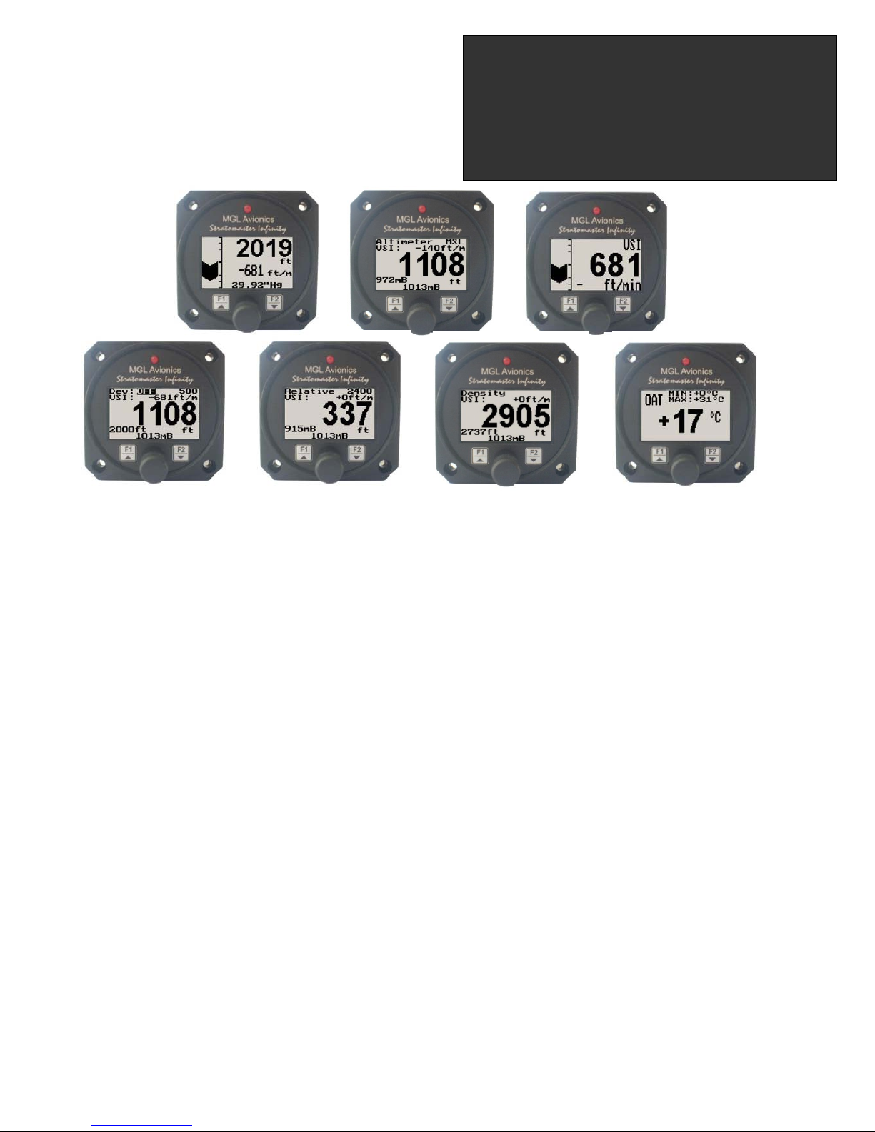
The ALT-1 is a 2 1/4” instrument that contains a precision encoding altimeter and a wide range vertical speed indicator.
The altimeter conforms to ANSI standard atmosphere rules from –1000 ft up to a maximum of 30 000 ft. The altimeter
includes an encoding serial output that when used in combination with MGL Avionics CNV-AT, provides a parallel Gillham
code interface for transponders. The altimeter can display altitude in feet or meters, local pressure can be set in millibars
or inches of mercury
The onboard VSI indicator is altitude compensated and can be displayed in either feet/minute (ft/min) or meters/second
(m/s). It also offers a digital readout with a wide range from +/-20 ft/min to as high as +/-10 000 ft/min, it also offers a
logarithmic analog display with a +/-2000 ft range. The VSI can be calibrated by the user once the instrument has been
installed in the aircraft.
In addition the ALT-1 provides an OAT sender which is used in determining the density altitude of the aircraft. The ALT-1
can also be used to measure relative altitude and it has a facility for the pilot to enter a reference altitude and deviation
band that has to be kept.
1 Features
• Precision altimeter from –1000 ft up to a maximum of 30 000 ft (-304m to 9144m)
• Provides altitude encoder data on airtalk (serial) output, which can be converted by a MGL Avionics CNVAT converter to a parallel Gillham code interface for transponders
• The altimeter can display altitude in feet or meters, local pressure can be set in millibars or inches of
mercury
• Contains a wide range VSI indicator from +/-20 ft/min to as high as +/-10 000 ft/min
• VSI units can be in feet/minute (ft/min) or in meters/second (m/s)
• Records the maximum and minimum OAT (outside air temperature) and maximum altitude reached in
permanent memory
• Records maximum and minimum OAT in temporary memory since instrument power up
• Standard 2 1/4” aircraft enclosure (can be front or rear mounted)
• Rotary control plus 2 independent buttons for easy menu navigation and user input
• Alarm output as well as a red LED illuminates when the alarm has been activated
• Large backlit graphic LCD with adjustable contrast
• Wide input supply voltage range of 8 to 30V DC with built in voltage reversal and over voltage protection
for harsh electrical environments
• Light weight design
• Field upgradeable firmware
• 1 year limited warranty
ALT-1
Precision Encoding Altimeter and
Vertical speed indicator (VSI)
Operating Manual – English 1.09
Page 2
ALT-1 Operating Manual Page 2
2 ALT-1 Layout
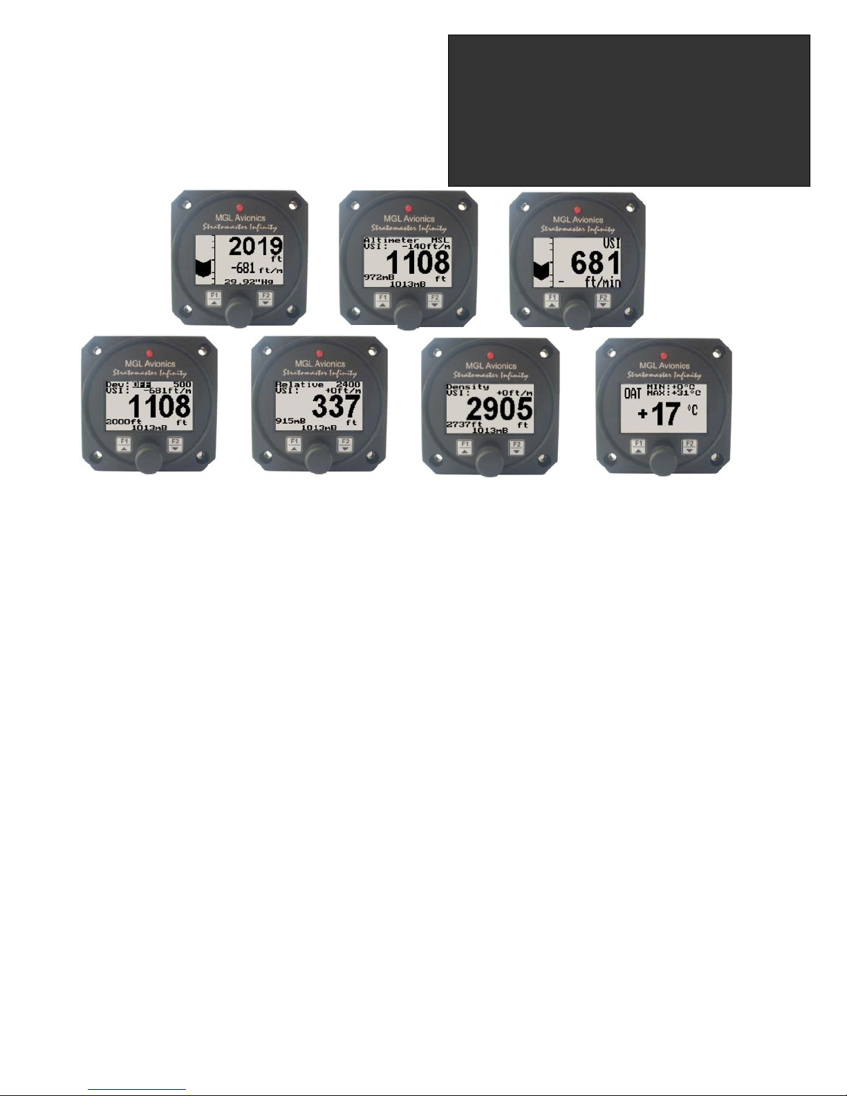
3 Main Display
The main displays can be toggled by pressing the F2/Down key.
3.1 Altitude and VSI display
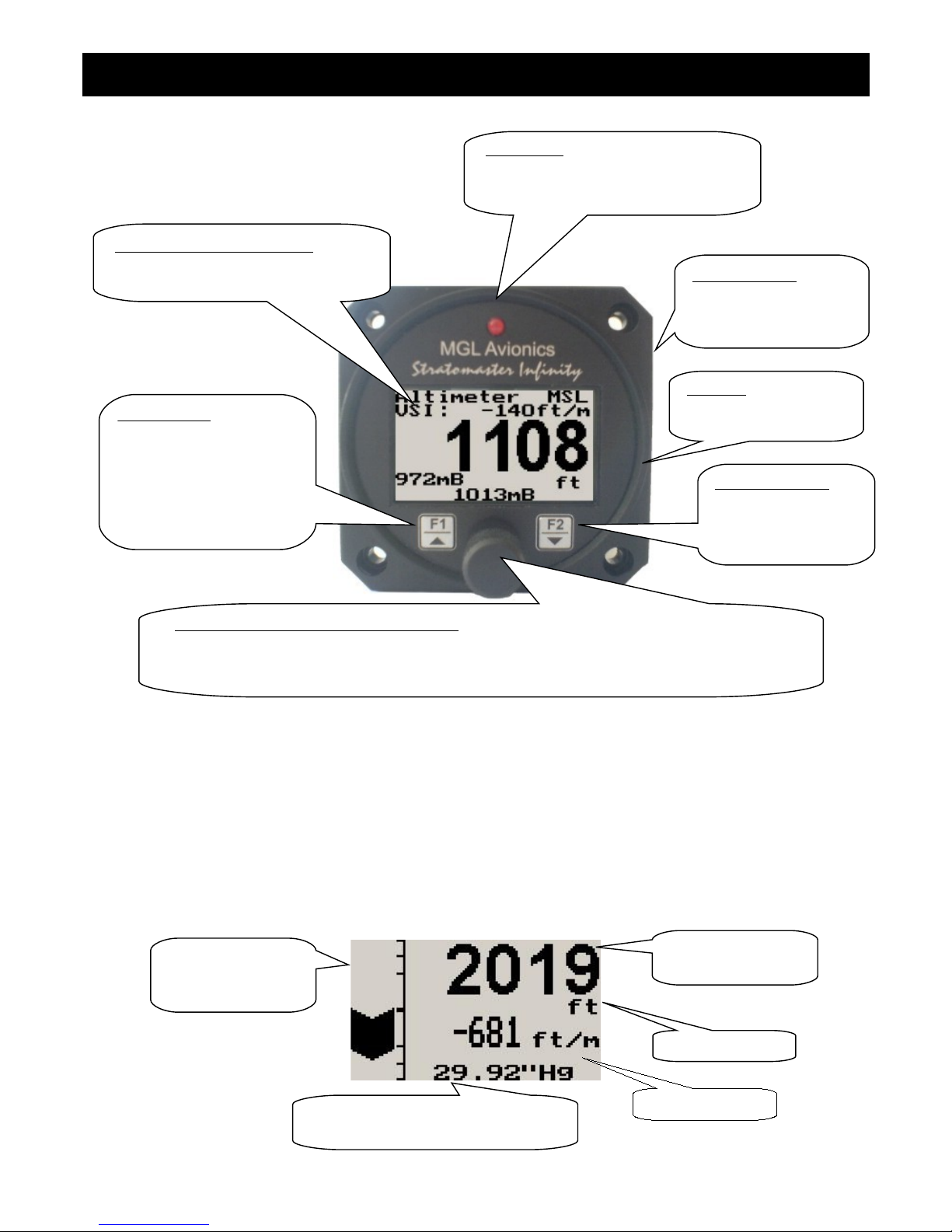
This is the standard display for the ALT-1. Use the rotary control to adjust the local pressure setting.
Backlit Graphic LCD Display:
Contrast and backlight can be adjusted
in the menu system
Harness:
Harness connects to
power
Up/F1 Button:
Up button in menu system
Deviation mode: Enter
reference altitude and
deviation band
Relative Mode: Enter
Down/F2 Button:
Down button in menu
system
Main display scrolling
Rotary Control (Up/Down) & Enter Button:
Press the rotary control during normal mode to access the menu system. Rotate anti/clockwise
for up/down menu scrolling. During normal mode rotating the rotary control will adjust the local
pressure setting. Local pressure can be set in either mB or in “Hg.
Pressure Ports:
Pressure ports connect
to the static pressure
tube
LED Alarm:
The red LED will illuminate if the
deviation band has been exceeded
when using the deviation altitude mode
Altitude unit
Local pressure readout (either in
millibars or in inches of mercury)
Logarithmic analog
VSI indicator
Altitude relative to
mean sea level
Digital VSI readout
Page 3
ALT-1 Operating Manual Page 3
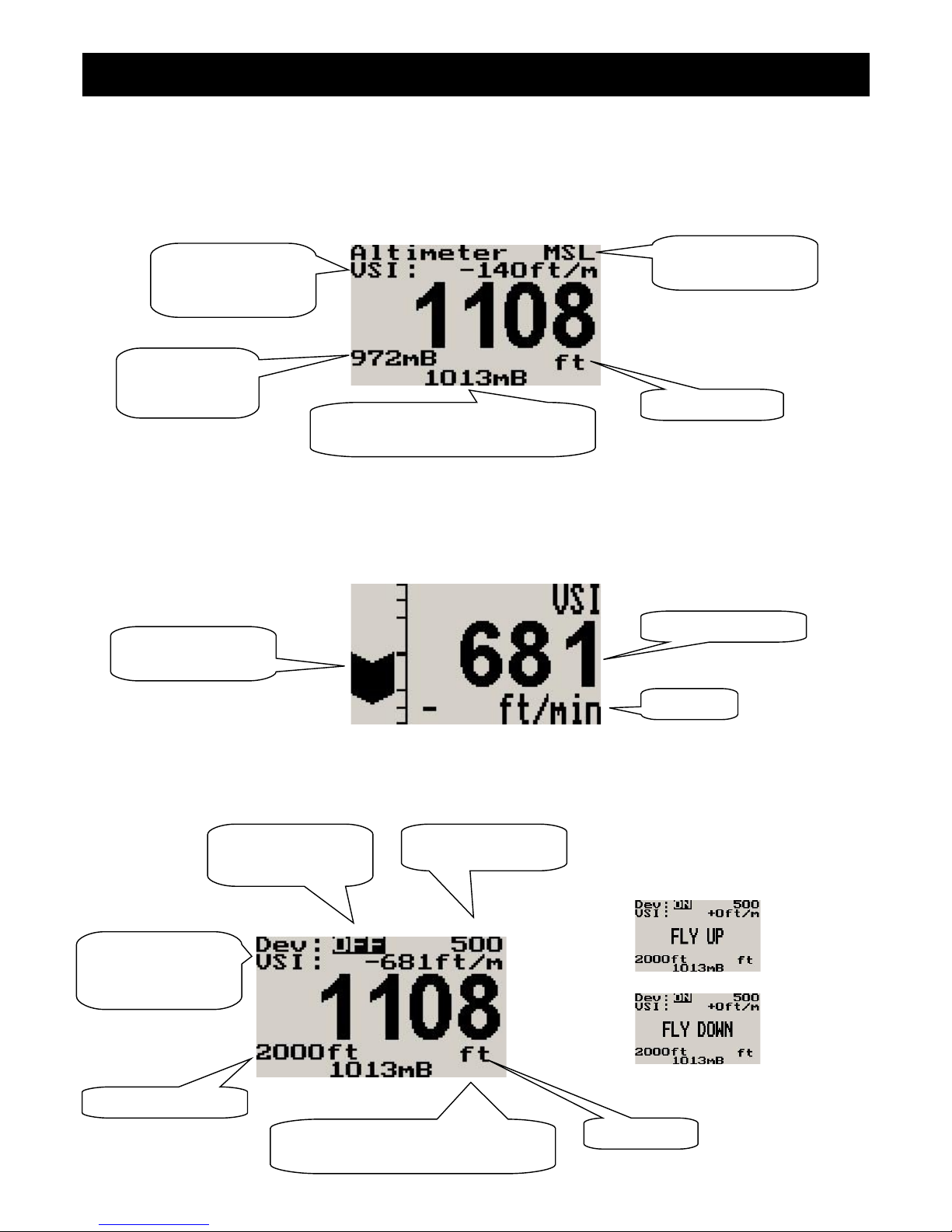
3.2 Altitude relative to sea level display
Use the rotary control to adjust the local pressure setting.
3.3 VSI (Vertical Speed Indicator)
The ALT-1 can be setup to be as a VSI (vertical speed indicator).
3.4 Deviation Altitude display
Display messages when band
has been exceeded
Digital VSI readout
Logarithmic analog
VSI indicator
VSI units
Local pressure readout (either in
millibars or in inches of mercury)
Altitude unit
Digital VSI readout,
can be turned off in
the menu system
Reference Altitude
Altitude deviation
function on/off
Altitude deviation
band
Altitude unit
Barometer, can
be turned off in
the menu system
Local pressure readout (either in
millibars or in inches of mercury)
Digital VSI readout,
can be turned off in
the menu system
Altitude relative to
mean sea level
Page 4
ALT-1 Operating Manual Page 4
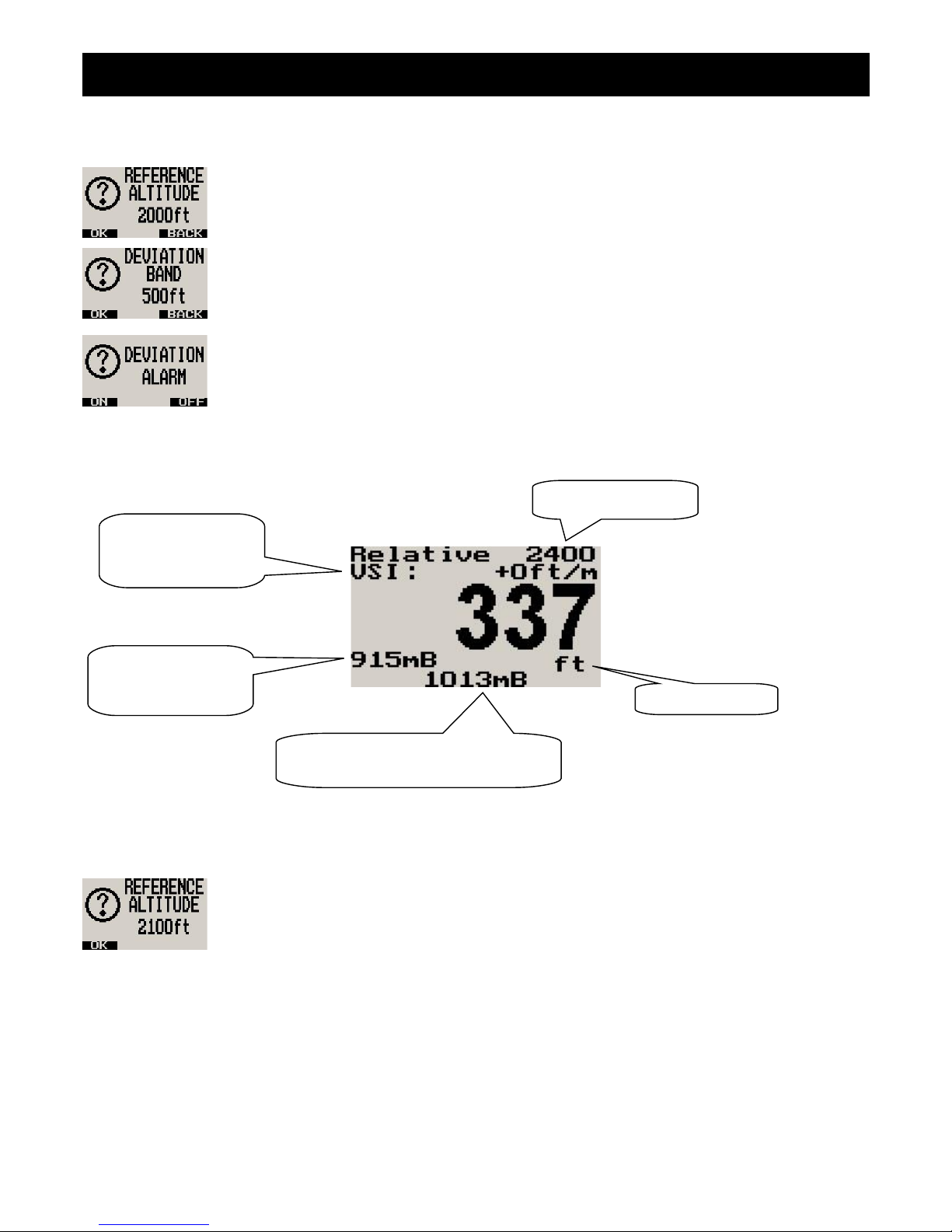
Use the rotary control to adjust the local pressure setting. Pressing the F1/up key will allow the pilot to enter a reference
altitude and the deviation band.
Adjust the reference altitude using the rotary control. This is the altitude that the pilot wants to
maintain. Press the F1 key to accept, press the F2 key to return to the main display.
Adjust the deviation band above and below your reference altitude that is still acceptable to fly in.
Any altitude outside this band will activate the alarm. Press the F1 key to accept, press the F2
button to return to the main display.
Select whether you want the altitude deviation feature enabled or not. Press the F1 key to enable
the altitude deviation feature, press the F2 key to disable the altitude deviation feature.
3.5 Relative Altitude display
Use the rotary control to adjust the local pressure setting. Pressing the F1/up key will allow the pilot to enter a reference
altitude.
Enter the reference altitude you would like to use in relative mode. Use the rotary control to adjust
the reference altitude. Press the F1/up key to accept.
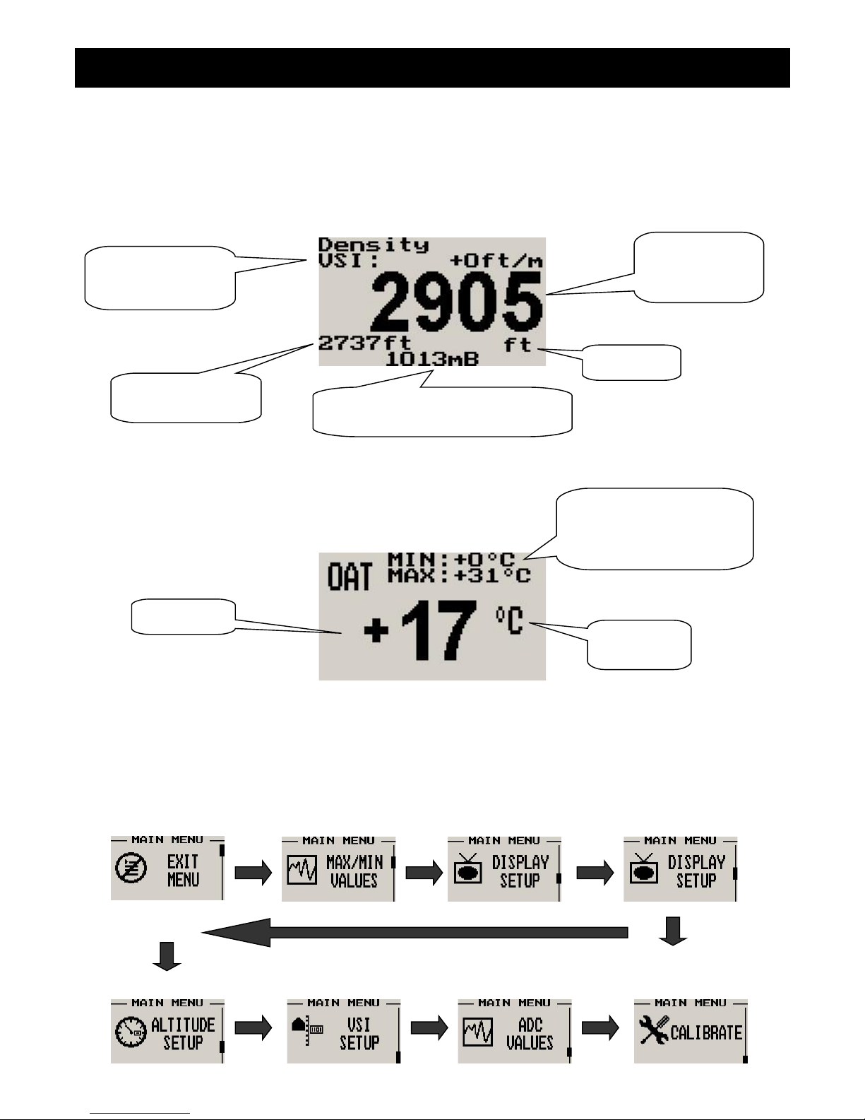
3.6 Density Altitude display
Density altitude is a perceived altitude that pertains to your current altitude and temperature (and to a lesser extent on
your current moisture content of the air). Density altitude is relevant for performance calculations of your aircraft. Density
altitude affects the performance of your engine, propeller and airfoils. The most noticeable affects of density altitude are
length of take-off and landing runs and the ability of your aircraft to carry weight. There are several methods to calculate
density altitude, all result in readings that are very close to each other. We decided to implement a popular formula that is
often used by pilots to calculate density altitude at their location.
Local pressure readout (either in
millibars or in inches of mercury)
Altitude unit
Barometer, can be
turned off in the
menu system
Digital VSI readout,
can be turned off in
the menu system
Reference Altitude
Page 5
ALT-1 Operating Manual Page 5
Da = Density altitude
Pa = Pressure altitude
T = ambient temperature in degrees C
Ts= 15 - 0.0019812 * pressure altitude (ft)
Da = Pa + 118.6 * (T-Ts)
3.7 OAT (Outside air temperature) Display
The OAT probe is used to determine density altitude.
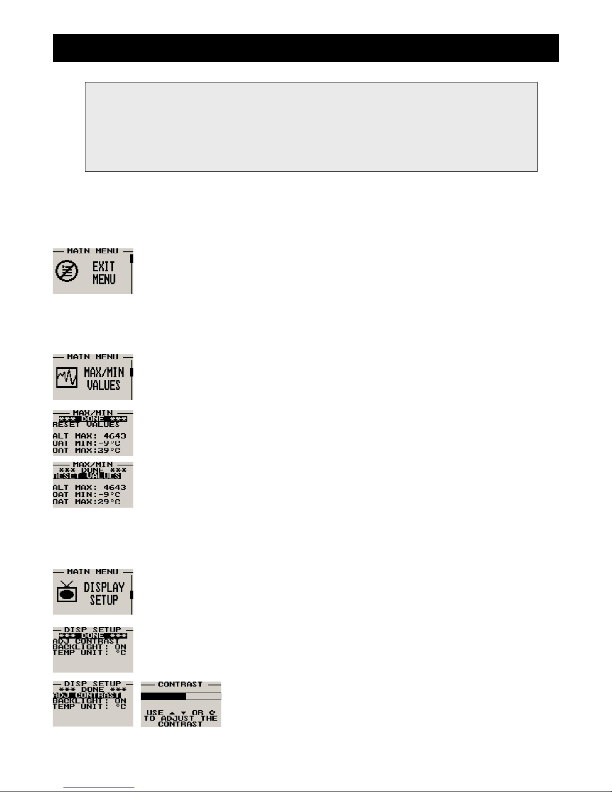
4 Menu System
Pressing the rotary control button during the normal display mode will cause the ALT-1 to enter the menu system. Use the
up/down keys or the rotary control to navigate through the menu system.
Temperature
unit
OAT reading
Temporary maximum and
minimum OAT since
instrument power up, reset
using the F1/up key
Local pressure readout (either in
millibars or in inches of mercury)
Digital VSI readout,
can be turned off in
the menu system
Compensated
density altitude
value
Altitude unit
Uncompensated
altitude value
Page 6
ALT-1 Operating Manual Page 6
4.1 Exit Menu
Pressing the rotary control on this menu item will cause the ALT-1 to exit the menu system. All
changes made during navigation of the menu system will be saved in non-volatile memory on exiting
the menu system. If you remove power before exiting the menu the instrument will not save any
changes.
4.2 Maximum Values
To avoid false recordings, the maximum values function is only activated 10 seconds after the
instrument has powered up.
Move the highlight over the “DONE” menu item and press the rotary button to return to the main
menu.
Move the highlight over this menu item and press the rotary button to reset the maximum altitude
and OAT values to the current values.
4.3 Display Setup
Move the highlight over this menu option and press the rotary button to return to the main menu.
Select this menu option to adjust the display contrast.
Note: (ADC Values and Calibrate Menus are only visible when powering up the unit and pressing the
Rotary Control). The text “CALIBRATE” will appear on the intro screen when entering this mode.
Warning: The Calibrate Menu is for technical personnel only. Changing any values in this menu may
cause the instrument to display incorrect information, and may require the instrument to be returned to
the factory for recalibration.
Page 7
ALT-1 Operating Manual Page 7
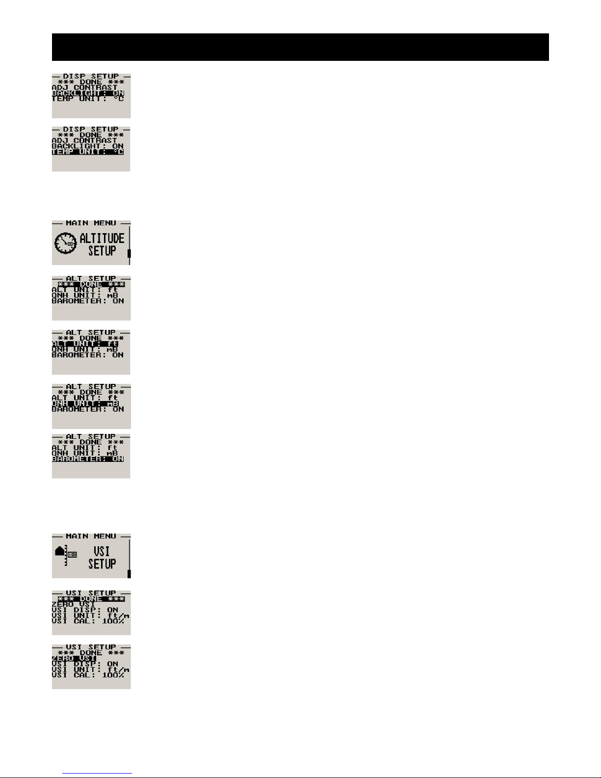
Select this menu option to turn the backlight on or off.
Select whether you want the OAT to be displayed in degress Fahrenheit (ºF) or in degrees Celcius
(ºC).
4.4 Altitude Setup
All altitude related parameters can be setup here.
Move the highlight over the “DONE” menu item and press the rotary button to return to the main
menu.
Select if you want your altitude readout in feet (ft) or meters (m).
Select if you want your local pressure readout in millibars (mB) or inches of mercury (“Hg).
Select if you want the barometer to be displayed on the altitude screens or not.
4.5 VSI (Vertical Speed Indicator) Setup
All VSI related parameters can be setup here.
Move the highlight over the “DONE” menu item and press the rotary button to return to the main
menu.
This function is used to set your VSI to read exactly 0ft/min. This is similar to setting the needle on a
mechanical VSI to point to zero by turning the adjustment knob on such a VSI. The electronic VSI
generally has much less drift compared to a mechanical VSI and this function will only be used very
occasionally. Ensure that you perform this function when no pressure changes due to wind or other
reasons are occurring.
Page 8
ALT-1 Operating Manual Page 8
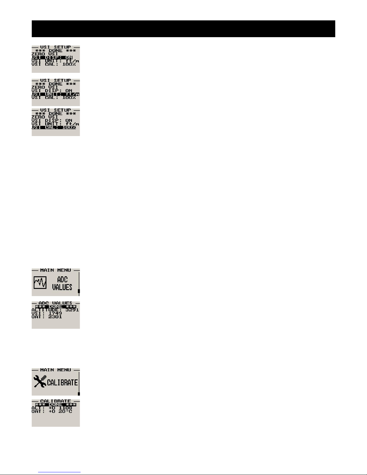
Select if you want to show the built in VSI (vertical speed indicator). The built in VSI will be shown
above the altitude readout.
Select if you want your VSI readout in feet/minute (ft/m) or meters/second (m/s).
Note: meters/second will be shown with two decimals, example: “1.23”.
This is a function that is used to calibrate your VSI to read exact rates of climb or decent. This
function works as a percentage of initial reading. The default setting for this function is 100%.
Increasing this value increases the VSI reading and decreasing the value decreases the reading.
Suggested VSI calibration method
After you have installed the instrument, perform a calibration flight. This should be done in very calm conditions.
Turbulence and thermal activity will make accurate calibration impossible. Many areas have ideal conditions during early
mornings or late afternoons. Place the instrument in “feet” unit mode for ease of calibration. Take your aircraft to a few
thousand feet above ground and start a glide with a low power setting. Take a stopwatch and when the glide is stable
(stable VSI reading) start the stopwatch. Take note of your altimeter reading at the same time. Continue the stable glide
for one minute exactly. After the minute has finished, take another reading of your altimeter.
Example:
VSI reading during stable glide: -400 ft/min
Start altitude: 2500 ft.
End altitude: 2050 ft.
In the above example the VSI is under reading by about 12%. Set your VSI calibration to 112% to cancel out the error.
4.6 ADC Values
Note: This menu item is for technical personnel only, and is not displayed during the normal
operation of the instrument. Please see section 4 above on how to access this menu item.
This menu displays the ADC values that have been read from the pressure sensors.
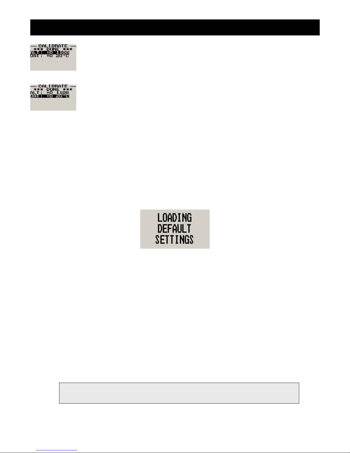
4.7 Calibrate
Note: This menu item is for technical personnel only, and is not displayed during the normal
operation of the instrument. Please see section 4 above on how to access this menu item. Consult
your local dealer or factory before entering this menu.
Move the highlight over the “DONE” menu item and press the rotary button to return to the main
menu.
Page 9
ALT-1 Operating Manual Page 9
On the back of the ALT-1 you will find the calibration number that has been determined to ensure
the most accurate reading of your altimeter. This is the value that should be entered here. Should
you have access to an accurate reference you may use this function to calibrate your altimeter.
Before you do this, ensure that you have your local pressure set to coincide with a calibrated and
certified reference. Your altimeter has been calibrated by the factory to an accuracy of +/- one mB or
approximately +/- 30 ft (10m).
The ALT-1 is calibrated in degrees Celsius. The ALT-1 is calibrated at the factory using a precision
laboratory thermometer. If recalibration is required then adjust the value using the up/down keys or
the rotary control until the temperature matches the reference ambient temperature.
5 Altitude Encoder
To use the ALT-1 as an encoding altimeter an Airtalk to parallel Gillham code output encoder such as the MGL Avionics
CNV-AT must be used. This converter takes the Airtalk serial string that is outputted by the ALT-1 and converts it to a
parallel Gillham code suitable for aircraft transponders. Please see the CNV-AT operating manual for more information.
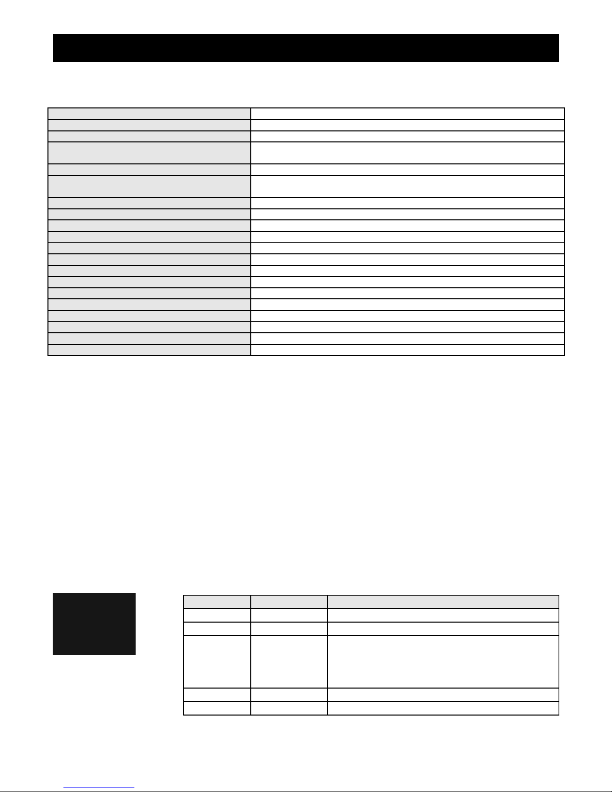
6 Loading factory default settings
Pressing and holding the F1 and F2 simultaneously on power up will cause the ALT-1 to load preprogrammed factory
default settings. The following screen will be displayed:
7 Operating the alarms
If the alarm is activated, the corresponding item on the display will flash. At the same time the externally available alarm
switch will close. The switch will remain closed until any button is pressed to acknowledge the alarm or until the
condition(s) that activated the alarm no longer exist. The alarm output can be used to switch an external alarm indicator.
The external alarm switch is an open collector transistor switch to ground with a maximum rating of 0.5A DC. It is possible
to wire the alarm contacts of several Stratomaster instruments in parallel should this be desired. To avoid false activation
of the alarms, the alarm function is only active 10 seconds after the instrument has powered up.
8 Cleaning
The unit should not be cleaned with any abrasive substances. The screen is very sensitive to certain cleaning materials
and should only be cleaned using a clean, damp cloth.
Warning: The ALT-1 is not waterproof, serious damage could occur if the unit is exposed to
water and/or spray jets.
Page 10
ALT-1 Operating Manual Page 10
9 ALT-1 Specifications
Operating Temperature Range -10ºC to 50ºC (14ºF to 122ºF)
Storage Temperature Range -20ºC to 80ºC (-4ºF to 176ºF)
Humidity <85% non-condensing
Power Supply
8 to 30Vdc SMPS (switch mode power supply) with built in 33V over
voltage and reverse voltage protection
Current Consumption Approx. 45mA @ 13.8V (backlight on) 15mA @13.8V (backlight off)
Display
114x64 graphic LCD display. Contrast and backlight is user configurable,
green/yellow backlight
ADC 12bit over sampled successive approximation
Dimensions see Infinity series dimensional drawing
Enclosure 2 1/4” ABS, black in color, front or rear mounting
Weight Approx. 120 grams
Alarm contact current rating Open collector transistor switch to ground. Maximum rating 0.5A DC
Non-volatile memory storage 100000 write cycles
Altimeter range -1000ft to 30 000ft (-304m to 9144m)
Altimeter resolution 1ft/1m
Altitude measurement accuracy +/- 1mB, +/- 30ft at sea level
Digital VSI range +/-20ft/m to +/-10 000ft/m
Digital VSI resolution 10ft
Analog VSI range +/-2000 ft/m, logarithmic scale
VSI measurement accuracy +/- 2%, relative to calibration
Airtalk protocol 19200 baud, 8 data bits, no parity, 1 stop bit (TTL voltage levels)
10 Installation
Connect the static port to a suitable static air pressure line. If you have a slow aircraft or an aircraft were the internal cabin
pressure does not change during flight and is equivalent to the outside air pressure you may find that it is not required to
connect a static port.
For installations in typical ultralight aircraft pods, be aware of possible pressure changes inside the pod during flight
caused by ram air or suction effects. This may lead to a false indication of altitude. Often these effects are dependent on
the current angle of attack of the airflow around your pod. You will need to install a suitable static port in these cases.
The use of an external 1A fuse is recommended. Connect the supply terminals to your aircrafts power supply. The ALT-1
can be used on both 12V and 24V without the use of any pre-regulators. Ensure that the supply voltage will not drop
below 8V during operation as this may result in incorrect readings.
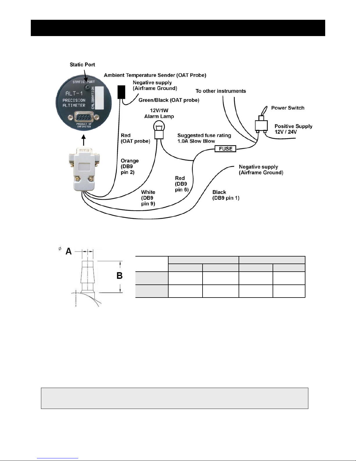
10.1 ALT-1 DB9 Cable connections
DB 9 Pin Color Function
1 Black Ground
2 Orange OAT Sensor
4 NC Airtalk communication (Not connected)
Used for firmware upgrading and
interfacing to the CNV-AT (Airtalk to
parallel Gillham code output encoder)
6 Red 8-30Vdc power
9 White Alarm Output
Page 11
ALT-1 Operating Manual Page 11
10.2 Connection Diagram
10.3 Pressure Port Dimensions
11 Warranty
This product carries a warranty for a period of one year from date of purchase against faulty workmanship or defective
materials, provided there is no evidence that the unit has been mishandled or misused. Warranty is limited to the
replacement of faulty components and includes the cost of labour. Shipping costs are for the account of the purchaser.
Damage as a result of applying excessive pressure to the pressure ports are excluded from warranty.
Inches Millimeters
Min Max Min Max
A
0.182 0.194 4.62 4.93
B
0.420 0.440 10.67 11.18
Note: Product warranty excludes damages caused by unprotected, unsuitable or incorrectly wired
electrical supplies and or sensors, and damage caused by inductive loads.
Page 12

ALT-1 Operating Manual Page 12
12 Disclaimer
Operation of this instrument is the sole responsibility of the purchaser of the unit. The user must make themselves familiar
with the operation of this instrument and the effect of any possible failure or malfunction.
This instrument is not certified by the FAA. Fitting of this instrument to certified aircraft is subject to the rules and
conditions pertaining to such in your country. Please check with your local aviation authorities if in doubt. This instrument
is intended for ultralight, microlight, homebuilt and experimental aircraft. Operation of this instrument is the sole
responsibility of the pilot in command (PIC) of the aircraft. This person must be proficient and carry a valid and relevant
pilot’s license. This person has to make themselves familiar with the operation of this instrument and the effect of any
possible failure or malfunction. Under no circumstances does the manufacturer condone usage of this instrument for IFR
flights.
Other instruments in the Stratomaster Infinity series
ALT-1 Precision encoding altimeter and vertical speed indicator
ALT-2 Precision encoding altimeter and vertical speed indicator with a serial RS232
transponder output
ASI-1 Airspeed indicator (ASI) with automatic flight log
ASX-1 Encoding aviation altimeter with serial output and airspeed indicator (ASI)
AV-1 Artificial horizon and magnetic compass indicator
BAT-1 Battery voltage and current monitor
E-3 Universal engine monitor
FF-1 Fuel Computer (single or dual fuel tanks)
GF-1 +-10G tilt compensated dual range G-force meter
MAP-1 Manifold pressure and RPM Indicator
RV-1 Universal engine RPM and rotor RPM Indicator
RV-2 Universal turbine RPM / RPM factor display
RTC-2 Aviation real time clock (RTC) and outside air temperature (OAT) display
TC-1 4-Channel thermocouple indicator
TP-1 Universal temperature and pressure gauge
The manufacturer reserves the right to alter any specification without notice.
Page 13
Introduction
The ALT-2 is a 2 1/4” instrument that contains a precision encoding altimeter and a wide range vertical speed indicator.
The altimeter conforms to ANSI standard atmosphere rules from –1000 ft up to a maximum of 30 000 ft. The ALT-2
outputs various formatted RS232 serial data protocols compatible with serial input transponders such as that from
Garmin, Magellan, Northstar, Trimble, Microair etc. The altimeter can display altitude in feet or meters, local pressure can
be set in millibars or inches of mercury
The onboard VSI indicator is altitude compensated and can be displayed in either feet/minute (ft/min) or meters/second
(m/s). It also offers a digital readout with a wide range from +/-20 ft/min to as high as +/-10 000 ft/min, it also offers a
logarithmic analog display with a +/-2000 ft range. The VSI can be calibrated by the user once the instrument has been
installed in the aircraft.
In addition the ALT-2 provides an OAT sender which is used in determining the density altitude of the aircraft. The ALT-2
can also be used to measure relative altitude and it has a facility for the pilot to enter a reference altitude and deviation
band that has to be kept.
1 Features
• Precision altimeter from –1000 ft up to a maximum of 30 000 ft (-304m to 9144m)
• The ALT-2 outputs various formatted RS232 serial data protocols compatible with serial input
transponders such as that from Garmin, Magellan, Northstar, Trimble, Microair etc.
• The altimeter can display altitude in feet or meters, local pressure can be set in millibars or inches of
mercury
• Contains a wide range VSI indicator from +/-20 ft/min to as high as +/-10 000 ft/min
• VSI units can be in feet/minute (ft/min) or in meters/second (m/s)
• Records the maximum and minimum OAT (outside air temperature) and maximum altitude reached in
permanent memory
• Records maximum and minimum OAT in temporary memory since instrument power up
• Standard 2 1/4” aircraft enclosure (can be front or rear mounted)
• Rotary control plus 2 independent buttons for easy menu navigation and user input
• Alarm output as well as a red LED illuminates when the alarm has been activated
• Large backlit graphic LCD with adjustable contrast
• Wide input supply voltage range of 8 to 30V DC with built in voltage reversal and over voltage protection
for harsh electrical environments
• Light weight design
• Field upgradeable firmware
• 1 year limited warranty
ALT-2
Precision Encoding Altimeter and
Vertical speed indicator (VSI) with a
serial RS232 transponder output
Operating Manual – English 1.05
Page 14
ALT-2 Operating Manual Page 2
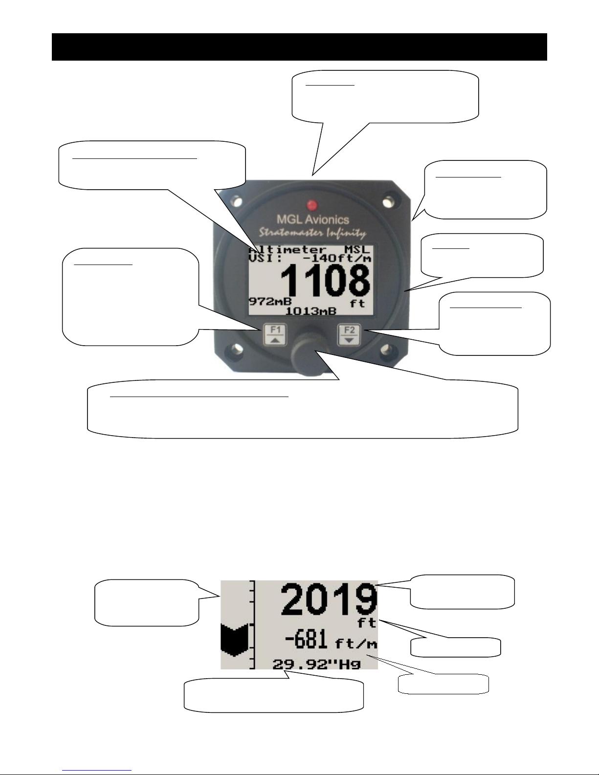
2 ALT-2 Layout
3 Main Display
The main displays can be toggled by pressing the F2/Down key.
3.1 Altitude and VSI display
This is the standard display for the ALT-2. Use the rotary control to adjust the local pressure setting.
Backlit Graphic LCD Display:
Contrast and backlight can be adjusted
in the menu system
Harness:
Harness connects to
power
Up/F1 Button:
Up button in menu system
Deviation mode: Enter
reference altitude and
deviation band
Relative Mode: Enter
Down/F2 Button:
Down button in menu
system
Main display scrolling
Rotary Control (Up/Down) & Enter Button:
Press the rotary control during normal mode to access the menu system. Rotate anti/clockwise
for up/down menu scrolling. During normal mode rotating the rotary control will adjust the local
pressure setting. Local pressure can be set in either mB or in “Hg.
Pressure Ports:
Pressure ports connect
to the static pressure
tube
LED Alarm:
The red LED will illuminate if the
deviation band has been exceeded
when using the deviation altitude mode
Altitude unit
Local pressure readout (either in
millibars or in inches of mercury)
Logarithmic analog
VSI indicator
Altitude relative to
mean sea level
Digital VSI readout
Page 15
ALT-2 Operating Manual Page 3
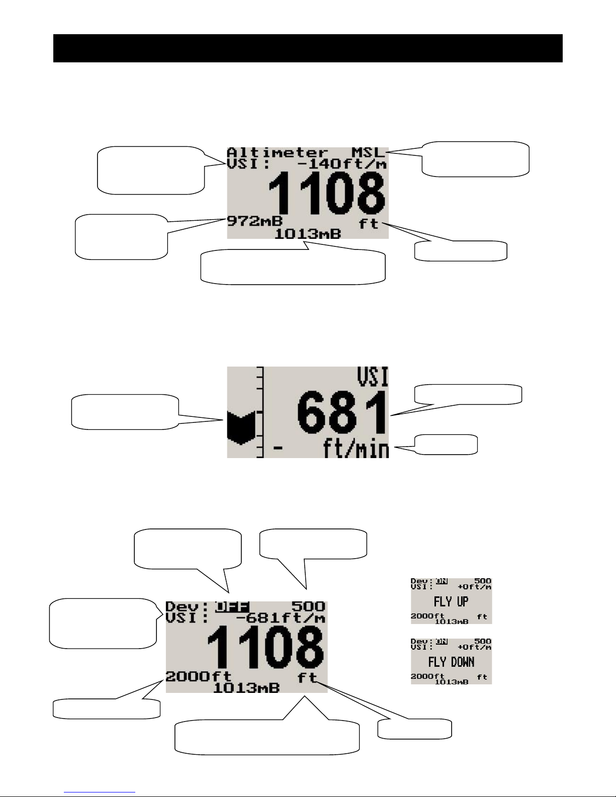
3.2 Altitude relative to sea level display
Use the rotary control to adjust the local pressure setting.
3.3 VSI (Vertical Speed Indicator)
The ALT-2 can be setup to be as a VSI (vertical speed indicator).
3.4 Deviation Altitude display
Display messages when band
has been exceeded
Altitude unit
Barometer, can
be turned off in
the menu system
Local pressure readout (either in
millibars or in inches of mercury)
Digital VSI readout
Logarithmic analog
VSI indicator
VSI units
Digital VSI readout,
can be turned off in
the menu system
Altitude relative to
mean sea level
Local pressure readout (either in
millibars or in inches of mercury)
Altitude unit
Digital VSI readout,
can be turned off in
the menu system
Reference Altitude
Altitude deviation
function on/off
Altitude deviation
band
Page 16
ALT-2 Operating Manual Page 4
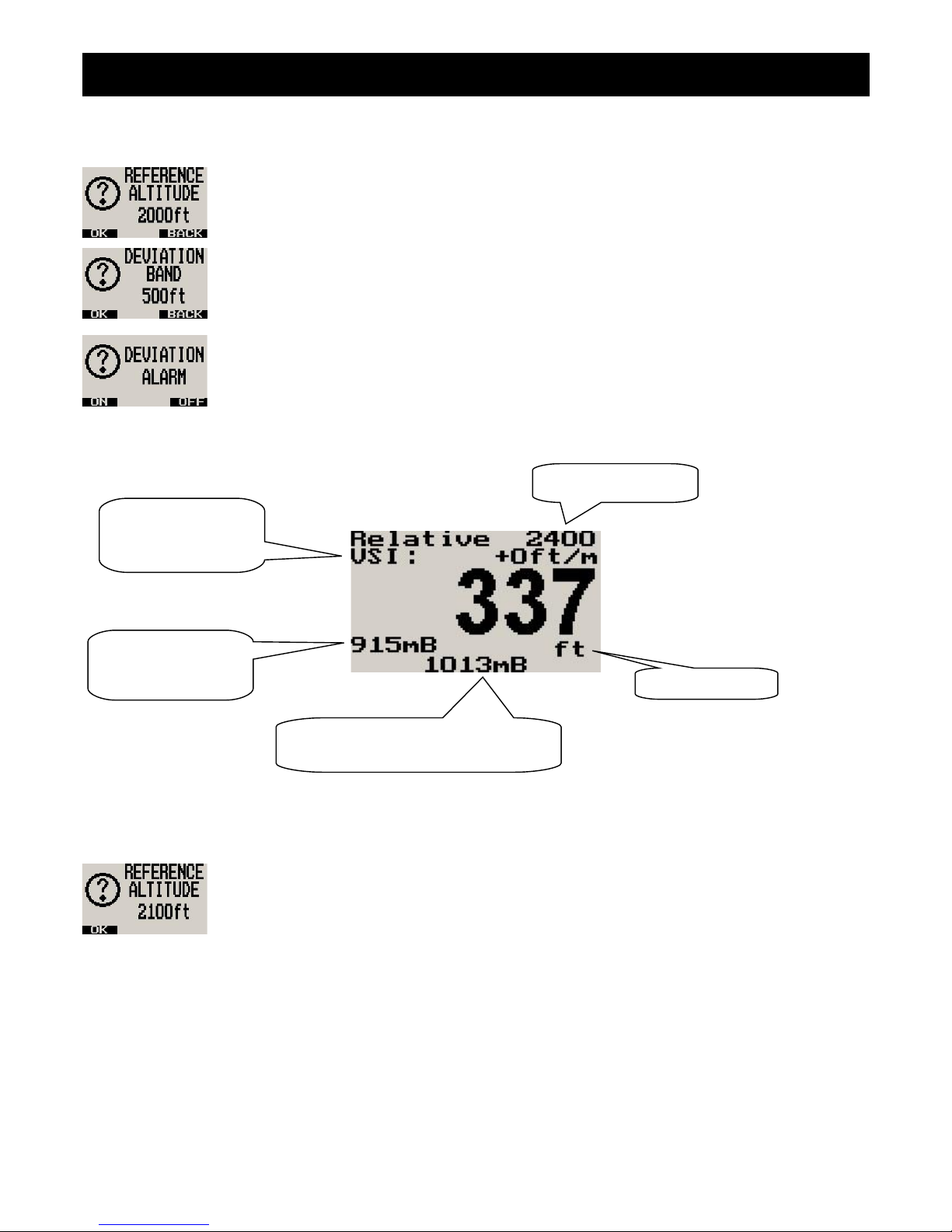
Use the rotary control to adjust the local pressure setting. Pressing the F1/up key will allow the pilot to enter a reference
altitude and the deviation band.
Adjust the reference altitude using the rotary control. This is the altitude that the pilot wants to
maintain. Press the F1 key to accept, press the F2 key to return to the main display.
Adjust the deviation band above and below your reference altitude that is still acceptable to fly in.
Any altitude outside this band will activate the alarm. Press the F1 key to accept, press the F2
button to return to the main display.
Select whether you want the altitude deviation feature enabled or not. Press the F1 key to enable
the altitude deviation feature, press the F2 key to disable the altitude deviation feature.
3.5 Relative Altitude display
Use the rotary control to adjust the local pressure setting. Pressing the F1/up key will allow the pilot to enter a reference
altitude.
Enter the reference altitude you would like to use in relative mode. Use the rotary control to adjust
the reference altitude. Press the F1/up key to accept.
3.6 Density Altitude display
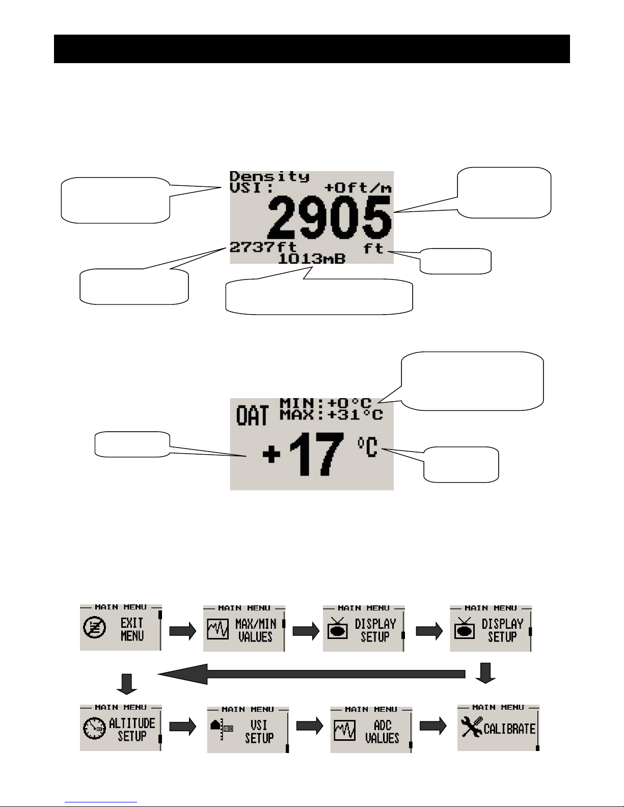
Density altitude is a perceived altitude that pertains to your current altitude and temperature (and to a lesser extent on
your current moisture content of the air). Density altitude is relevant for performance calculations of your aircraft. Density
altitude affects the performance of your engine, propeller and airfoils. The most noticeable affects of density altitude are
length of take-off and landing runs and the ability of your aircraft to carry weight. There are several methods to calculate
density altitude, all result in readings that are very close to each other. We decided to implement a popular formula that is
often used by pilots to calculate density altitude at their location.
Local pressure readout (either in
millibars or in inches of mercury)
Altitude unit
Barometer, can be
turned off in the
menu system
Digital VSI readout,
can be turned off in
the menu system
Reference Altitude
Page 17
ALT-2 Operating Manual Page 5
Da = Density altitude
Pa = Pressure altitude
T = ambient temperature in degrees C
Ts= 15 - 0.0019812 * pressure altitude (ft)
Da = Pa + 118.6 * (T-Ts)
3.7 OAT (Outside air temperature) Display
The OAT probe is used to determine density altitude.
4 Menu System
Pressing the rotary control button during the normal display mode will cause the ALT-2 to enter the menu system. Use the
up/down keys or the rotary control to navigate through the menu system.
Temperature
unit
OAT reading
Temporary maximum and
minimum OAT since
instrument power up, reset
using the F1/up key
Local pressure readout (either in
millibars or in inches of mercury)
Digital VSI readout,
can be turned off in
the menu system
Compensated
density altitude
value
Altitude unit
Uncompensated
altitude value
Page 18
ALT-2 Operating Manual Page 6
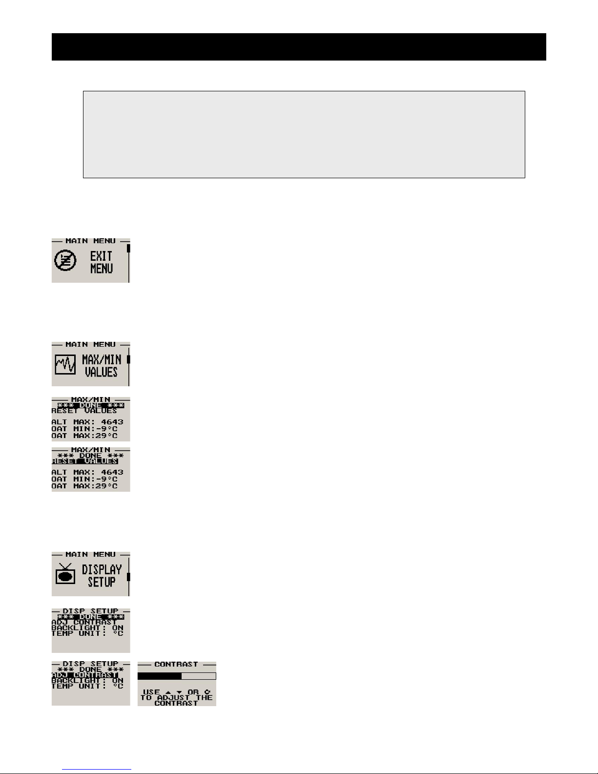
4.1 Exit Menu
Pressing the rotary control on this menu item will cause the ALT-2 to exit the menu system. All
changes made during navigation of the menu system will be saved in non-volatile memory on exiting
the menu system. If you remove power before exiting the menu the instrument will not save any
changes.
4.2 Maximum Values
To avoid false recordings, the maximum values function is only activated 10 seconds after the
instrument has powered up.
Move the highlight over the “DONE” menu item and press the rotary button to return to the main
menu.
Move the highlight over this menu item and press the rotary button to reset the maximum altitude
and OAT values to the current values.
4.3 Display Setup
Move the highlight over this menu option and press the rotary button to return to the main menu.
Select this menu option to adjust the display contrast.
Note: (ADC Values and Calibrate Menus are only visible when powering up the unit and pressing the
Rotary Control). The text “CALIBRATE” will appear on the intro screen when entering this mode.
Warning: The Calibrate Menu is for technical personnel only. Changing any values in this menu may
cause the instrument to display incorrect information, and may require the instrument to be returned to
the factory for recalibration.
Page 19
ALT-2 Operating Manual Page 7
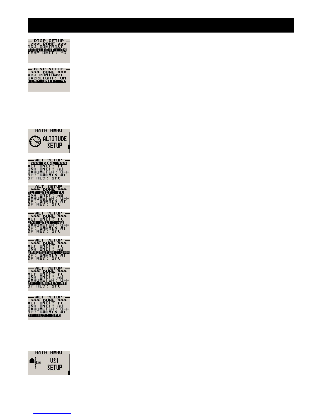
Select this menu option to turn the backlight on or off.
Select whether you want the OAT to be displayed in degress Fahrenheit (ºF) or in degrees Celcius
(ºC).
4.4 Altitude Setup
All altitude related parameters can be setup here.
Move the highlight over the “DONE” menu item and press the rotary button to return to the main
menu.
Select if you want your altitude readout in feet (ft) or meters (m).
Select if you want your local pressure readout in millibars (mB) or inches of mercury (“Hg).
Select if you want the barometer to be displayed on the altitude screens or not.
Select the protocol of the RS232 output message. The protocol can be selected between GARMIN
AT, Magellan, Northstar/Garmin, Trimble/Garmin, MGL Avionics and Microair UAV. Please see
section 5 for more information.
Select the resolution of the output data, a selection of 1,10,25 or 100 ft can be made.
4.5 VSI (Vertical Speed Indicator) Setup
All VSI related parameters can be setup here.
Page 20
ALT-2 Operating Manual Page 8
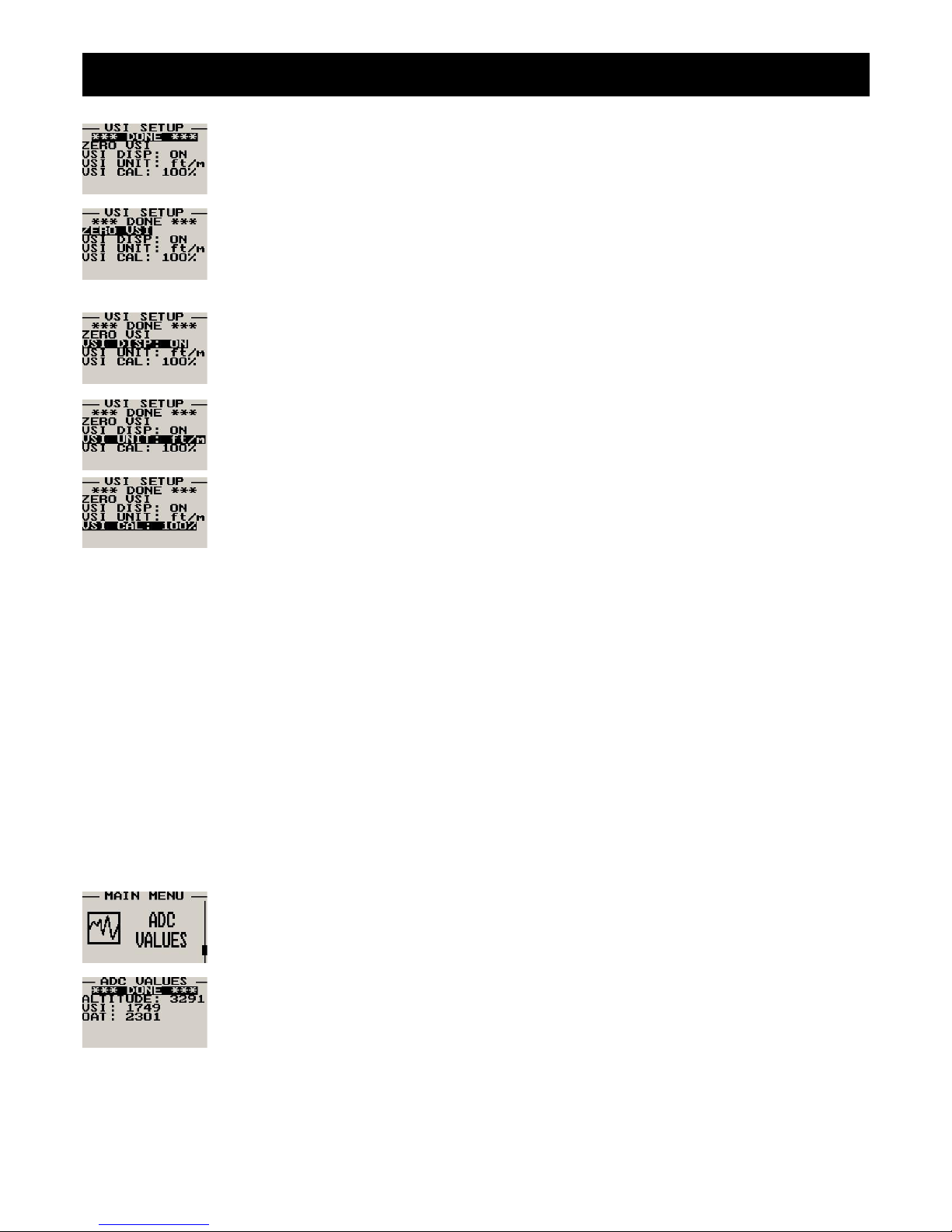
Move the highlight over the “DONE” menu item and press the rotary button to return to the main
menu.
This function is used to set your VSI to read exactly 0ft/min. This is similar to setting the needle on a
mechanical VSI to point to zero by turning the adjustment knob on such a VSI. The electronic VSI
generally has much less drift compared to a mechanical VSI and this function will only be used very
occasionally. Ensure that you perform this function when no pressure changes due to wind or other
reasons are occurring.
Select if you want to show the built in VSI (vertical speed indicator). The built in VSI will be shown
above the altitude readout.
Select if you want your VSI readout in feet/minute (ft/m) or meters/second (m/s).
Note: meters/second will be shown with two decimals, example: “1.23”.
This is a function that is used to calibrate your VSI to read exact rates of climb or decent. This
function works as a percentage of initial reading. The default setting for this function is 100%.
Increasing this value increases the VSI reading and decreasing the value decreases the reading.
Suggested VSI calibration method
After you have installed the instrument, perform a calibration flight. This should be done in very calm conditions.
Turbulence and thermal activity will make accurate calibration impossible. Many areas have ideal conditions during early
mornings or late afternoons. Place the instrument in “feet” unit mode for ease of calibration. Take your aircraft to a few
thousand feet above ground and start a glide with a low power setting. Take a stopwatch and when the glide is stable
(stable VSI reading) start the stopwatch. Take note of your altimeter reading at the same time. Continue the stable glide
for one minute exactly. After the minute has finished, take another reading of your altimeter.
Example:
VSI reading during stable glide: -400 ft/min
Start altitude: 2500 ft.
End altitude: 2050 ft.
In the above example the VSI is under reading by about 12%. Set your VSI calibration to 112% to cancel out the error.
4.6 ADC Values
Note: This menu item is for technical personnel only, and is not displayed during the normal
operation of the instrument. Please see section 4 above on how to access this menu item.
This menu displays the ADC values that have been read from the pressure sensors.
Page 21
ALT-2 Operating Manual Page 9
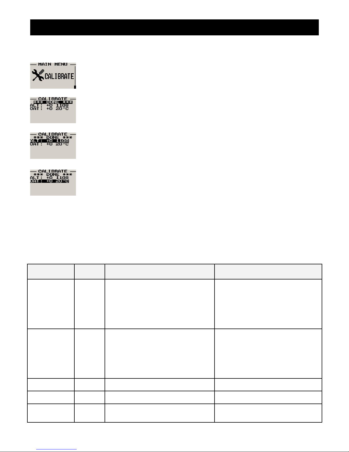
4.7 Calibrate
Note: This menu item is for technical personnel only, and is not displayed during the normal
operation of the instrument. Please see section 4 above on how to access this menu item. Consult
your local dealer or factory before entering this menu.
Move the highlight over the “DONE” menu item and press the rotary button to return to the main
menu.
On the back of the ALT-2 you will find the calibration number that has been determined to ensure
the most accurate reading of your altimeter. This is the value that should be entered here. Should
you have access to an accurate reference you may use this function to calibrate your altimeter.
Before you do this, ensure that you have your local pressure set to coincide with a calibrated and
certified reference. Your altimeter has been calibrated by the factory to an accuracy of +/- one mB or
approximately +/- 30 ft (10m).
The ALT-2 is calibrated in degrees Celcius. The ALT-2 is calibrated at the factory using a precision
laboratory thermometer. If recalibration is required then adjust the value using the up/down keys or
the rotary control until the temperature matches the reference ambient temperature.
5 Serial RS232 Altitude Encoder output
The ALT-2 outputs a formatted serial RS232 message that can be directly interfaced to various RS232 serial input
transponders such as those from Garmin, Trimble, Magellan, Northstar and Microair. The message contains the current
pressure altitude with a fixed reference to 1013.25mB (29.92 inches mercury). All protocols use 8 databits, no parity, and
1 stop bit. The message is outputted once a second.
Protocol Baud
Rate
Message format Example
Garmin AT 1200 #AL, space, +/-, five altitude digits right
justified zero padded, T+25, checksum,
carriage return
The checksum is a simple modulo 256 sum
of the binary values of the individual
characters. The checksum is sent as two
characters in hexadecimal format
#AL +02372T+25DF[CR]
Magellan 1200 #MGL, +/-, five altitude digits right justified
zero padded, T+25, checksum, carriage
return
The checksum is a simple modulo 256 sum
of the binary values of the individual
characters. The checksum is sent as two
characters in hexadecimal format
$MGL+02372T+2513[CR]
Northstar,
Garmin
4800 ALT, space, five altitude digits right justified
zero padded, carriage return
ALT 02372[CR]
Trimble, Garmin 9600 ALT, space, five altitude digits right justified
zero padded, carriage return
ALT 02372[CR]
MGL Avionics 9600 ALT, +/-, five altitude digits right justified
zero padded ,1013.25mB (29.92”Hg)
referenced, C, +/-, five altitude digits right
ALT+02372C+02372L1013+0000XCA[CR]
Page 22
ALT-2 Operating Manual Page 10
justified zero padded (corrected to local
pressure), L, local pressure setting in
millibars,+/-, four digit VSI reading right
justified zero padded in ft/min, X,
checksum, carriage return
The checksum is a simple modulo 256 sum
of the binary values of the individual
characters. The checksum is sent as two
characters in hexadecimal format
Microair UAV 9600 STX,a,=, five altitude digits right justified
zero padded, ETX
[STX]a=02372[ETX]
STX=0x02
ETX=0x03
CR=0x0D
6 Loading factory default settings
Pressing and holding the F1 and F2 simultaneously on power up will cause the ALT-2 to load preprogrammed factory
default settings. The following screen will be displayed:
7 Operating the alarms
If the alarm is activated, the corresponding item on the display will flash. At the same time the externally available alarm
switch will close. The switch will remain closed until any button is pressed to acknowledge the alarm or until the
condition(s) that activated the alarm no longer exist. The alarm output can be used to switch an external alarm indicator.
The external alarm switch is an open collector transistor switch to ground with a maximum rating of 0.5A DC. It is possible
to wire the alarm contacts of several Stratomaster instruments in parallel should this be desired. To avoid false activation
of the alarms, the alarm function is only active 10 seconds after the instrument has powered up.
8 Cleaning
The unit should not be cleaned with any abrasive substances. The screen is very sensitive to certain cleaning materials
and should only be cleaned using a clean, damp cloth.
Warning: The ALT-2 is not waterproof, serious damage could occur if the unit is exposed to
water and/or spray jets.
Page 23
ALT-2 Operating Manual Page 11
9 ALT-2 Specifications
Operating Temperature Range -10ºC to 50ºC (14ºF to 122ºF)
Storage Temperature Range -20ºC to 80ºC (-4ºF to 176ºF)
Humidity <85% non-condensing
Power Supply
8 to 30Vdc SMPS (switch mode power supply) with built in 33V over
voltage and reverse voltage protection
Current Consumption Approx. 45mA @ 13.8V (backlight on) 15mA @13.8V (backlight off)
Display
114x64 graphic LCD display. Contrast and backlight is user configurable,
green/yellow backlight
ADC 12bit over sampled successive approximation
Dimensions see Infinity series dimensional drawing
Enclosure 2 1/4” ABS, black in color, front or rear mounting
Weight Approx. 140 grams
Alarm contact current rating Open collector transistor switch to ground. Maximum rating 0.5A DC
Non-volatile memory storage 100000 write cycles
Altimeter range -1000ft to 30 000ft (-304m to 9144m)
Altimeter resolution 1ft/1m
Altitude measurement accuracy +/- 1mB, +/- 30ft at sea level
Digital VSI range +/-20ft/m to +/-10 000ft/m
Digital VSI resolution 10ft
Analog VSI range +/-2000 ft/m, logarithmic scale
VSI measurement accuracy +/- 2%, relative to calibration
RS232 protocol
Various baud rates, 8 data bits, no parity, 1 stop bit (RS232 voltage
levels). See section 5 for more details
10 Installation
Connect the static port to a suitable static air pressure line. If you have a slow aircraft or an aircraft were the internal cabin
pressure does not change during flight and is equivalent to the outside air pressure you may find that it is not required to
connect a static port.
For installations in typical ultralight aircraft pods, be aware of possible pressure changes inside the pod during flight
caused by ram air or suction effects. This may lead to a false indication of altitude. Often these effects are dependent on
the current angle of attack of the airflow around your pod. You will need to install a suitable static port in these cases.
The use of an external 1A fuse is recommended. Connect the supply terminals to your aircrafts power supply. The ALT-2
can be used on both 12V and 24V without the use of any pre-regulators. Ensure that the supply voltage will not drop
below 8V during operation as this may result in incorrect readings.
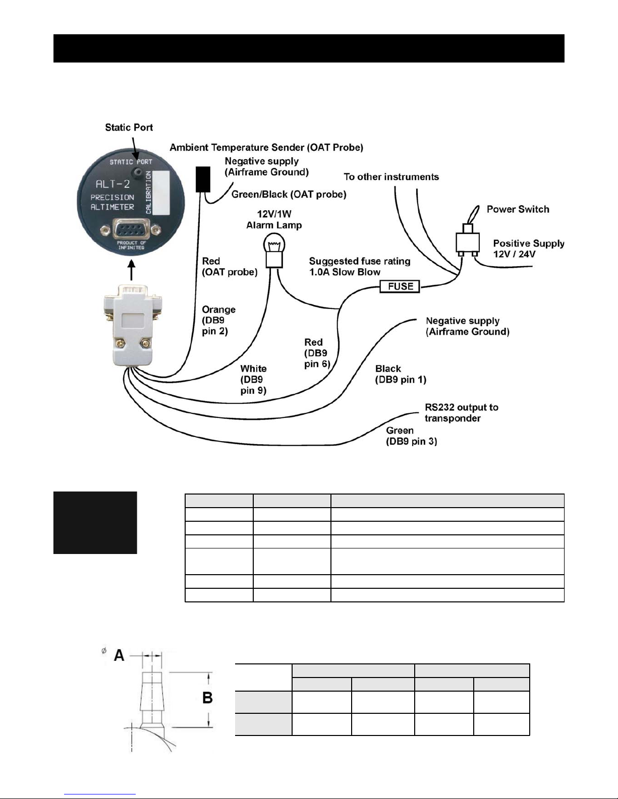
10.1 Connecting the ALT-2 to your transponder:
The ALT-2 has a RS232 serial output. Connect the RS232 output wire (DB9 pin 3 - green) to the transponders RX input
pin. Make sure that the ALT-2 ground is connected to the transponders minus terminal or to the RS232 ground if
available.
Consult your transponder manual for information on the transponder connector. You may need to enable the serial input
on your transponder and select a protocol. Select a protocol that is supported by both the ALT-2 and the transponder.
NOTE: Your country may have regulations that do not allow you to install a transponder or an encoding
altimeter yourself. The installation may have to be performed by an authorized person or company. Please check
your applicable regulations with your aviation authorities.
Page 24
ALT-2 Operating Manual Page 12
10.2 Connection Diagram
10.3 ALT-2 DB9 Cable connections
10.4 Pressure Port Dimensions
DB 9 Pin Color Function
1 Black Ground
2 Orange OAT Sensor
3 Green RS232 Output to transponder
4 NC Airtalk communication (Not connected)
Used for firmware upgrading
6 Red 8-30Vdc power
9 White Alarm Output
Inches Millimeters
Min Max Min Max
A
0.182 0.194 4.62 4.93
B
0.420 0.440 10.67 11.18
Page 25

ALT-2 Operating Manual Page 13
11 Warranty
This product carries a warranty for a period of one year from date of purchase against faulty workmanship or defective
materials, provided there is no evidence that the unit has been mishandled or misused. Warranty is limited to the
replacement of faulty components and includes the cost of labour. Shipping costs are for the account of the purchaser.
Damage as a result of applying excessive pressure to the pressure ports are excluded from warranty.
12 Disclaimer
Operation of this instrument is the sole responsibility of the purchaser of the unit. The user must make themselves familiar
with the operation of this instrument and the effect of any possible failure or malfunction.
This instrument is not certified by the FAA. Fitting of this instrument to certified aircraft is subject to the rules and
conditions pertaining to such in your country. Please check with your local aviation authorities if in doubt. This instrument
is intended for ultralight, microlight, homebuilt and experimental aircraft. Operation of this instrument is the sole
responsibility of the pilot in command (PIC) of the aircraft. This person must be proficient and carry a valid and relevant
pilot’s license. This person has to make themselves familiar with the operation of this instrument and the effect of any
possible failure or malfunction. Under no circumstances does the manufacturer condone usage of this instrument for IFR
flights.
Other instruments in the Stratomaster Infinity series
ALT-1 Precision encoding altimeter and vertical speed indicator
ALT-2 Precision encoding altimeter and vertical speed indicator with a serial RS232
transponder output
ASI-1 Airspeed indicator (ASI) with automatic flight log
ASX-1 Encoding aviation altimeter with serial output and airspeed indicator (ASI)
AV-1 Artificial horizon and magnetic compass indicator
BAT-1 Battery voltage and current monitor
E-3 Universal engine monitor
FF-1 Fuel Computer (single or dual fuel tanks)
GF-1 +-10G tilt compensated dual range G-force meter
MAP-1 Manifold pressure and RPM Indicator
RV-1 Universal engine RPM and rotor RPM Indicator
RV-2 Universal turbine RPM / RPM factor display
RTC-2 Aviation real time clock (RTC) and outside air temperature (OAT) display
TC-1 4-Channel thermocouple indicator
TP-1 Universal temperature and pressure gauge
Note: Product warranty excludes damages caused by unprotected, unsuitable or incorrectly wired
electrical supplies and or sensors, and damage caused by inductive loads.
The manufacturer reserves the right to alter any specification without notice.
Page 26
Introduction
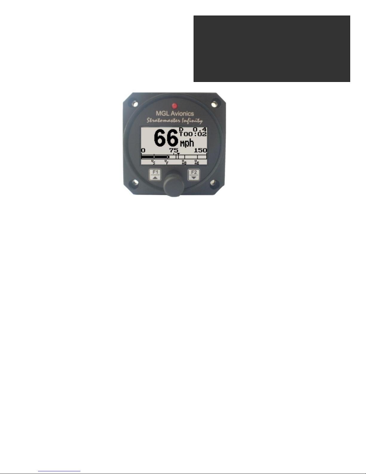
The ASI-1 airspeed indicator is a 2 1/4” instrument that provides a wide range airspeed indication in both digital and
analog formats. Airspeed is based on the pressure generated by a pitot tube system and a static port is provided as well
for use by high speed aircraft. In addition, the ASI-1 provides a 24 entry automatic flight log that stores the duration of
each of the last 24 flights, an air-distance trip counter and a current flight timer. Airspeed can be indicated in statute miles
per hour (mph), kilometers per hour (km/h) or nautical miles per hour (knots) with the air-distance being displayed in
corresponding units. The analog airspeed display can be scaled according to the aircraft’s flying speed range and
markers for Vs, Vf, Vno and Vne can be set. ASI sensitivity can be calibrated by the user to cater for errors caused by
pitot tube placement. The ASI-1 instrument measures airspeed from 16mph to 250mph and is well suited to slower
aircraft due to very good sensitivity and linearity at low air speeds.
The ASI-1 also outputs airspeed information via the airtalk protocol for interfacing to the Infinity FF-1 (fuel flow computer
for single or dual fuel tanks) and the SP-X (AHRS) instruments
1 Features
• Measure airspeed from 16mph to 250mph and is well suited to slow aircraft due to very good sensitivity
and linearity at low air speeds
• Includes a 24 entry automatic flight log
• Includes an air-distance trip counter and a flight timer
• Airspeed units can be set to miles per hour (mph), kilometer per hour (km/h) or nautical miles per hour
(knots)
• Contains a programmable low/high airspeed alarm
• Records maximum airspeed reached in permanent memory
• Analog bar graph indicating airspeed with markers for Vs, Vf, Vno and Vne
• Outputs airspeed information via the airtalk protocol for interfacing to the Infinity FF-1 (fuel flow computer
for single or dual fuel tanks) and the SP-X (AHRS) instruments
• Standard 2 1/4” aircraft enclosure (can be front or rear mounted)
• Rotary control plus 2 independent buttons for easy menu navigation and user input
• External alarm output as well as a red LED illuminates when the alarm has been activated
• Large backlit graphic LCD with adjustable contrast
• Wide input supply voltage range of 8 to 30V DC with built in voltage reversal and over voltage protection
for harsh electrical environments
• Light weight design
• 1 year limited warranty
ASI-1
Airspeed Indicator (ASI) with
automatic flight log
Operating Manual – English 1.06
Page 27
ASI-1 Operating Manual Page 2
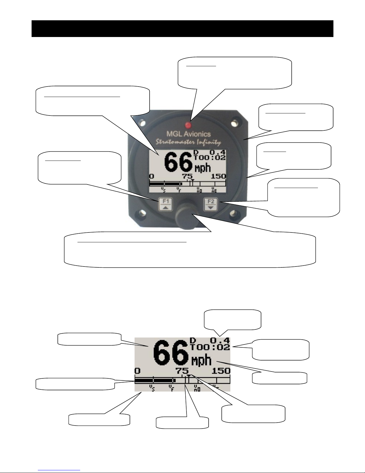
2 ASI-1 Layout
3 Main Display
Backlit Graphic LCD Display:
Contrast and backlight can be adjusted
in the menu system
Harness:
Harness connects to
power
Up/F1 Button:
Up button in menu system
Start/Stop flight in normal
mode
Down/F2 Button:
Down button in menu
system
Reset air distance trip
Rotary Control (Up/Down) & Enter Button:
Press the rotary control during normal mode to access the menu system. Rotate
anti/clockwise for up/down menu scrolling. During normal mode rotating the rotary control
will display the permanent memory maximum recorded airspeed.
Pressure Ports:
Pressure ports connect
to static and pitot tubes
LED Alarm:
The red LED will illuminate if the
airspeed alarm set-point has been
exceeded
Airspeed units
Air distance trip
counter
Analog airspeed display
Digital airspeed
Duration of flight
since take-off
Maximum airspeed
reached marker
Airspeed alarm
Airspeed markers
Page 28
ASI-1 Operating Manual Page 3
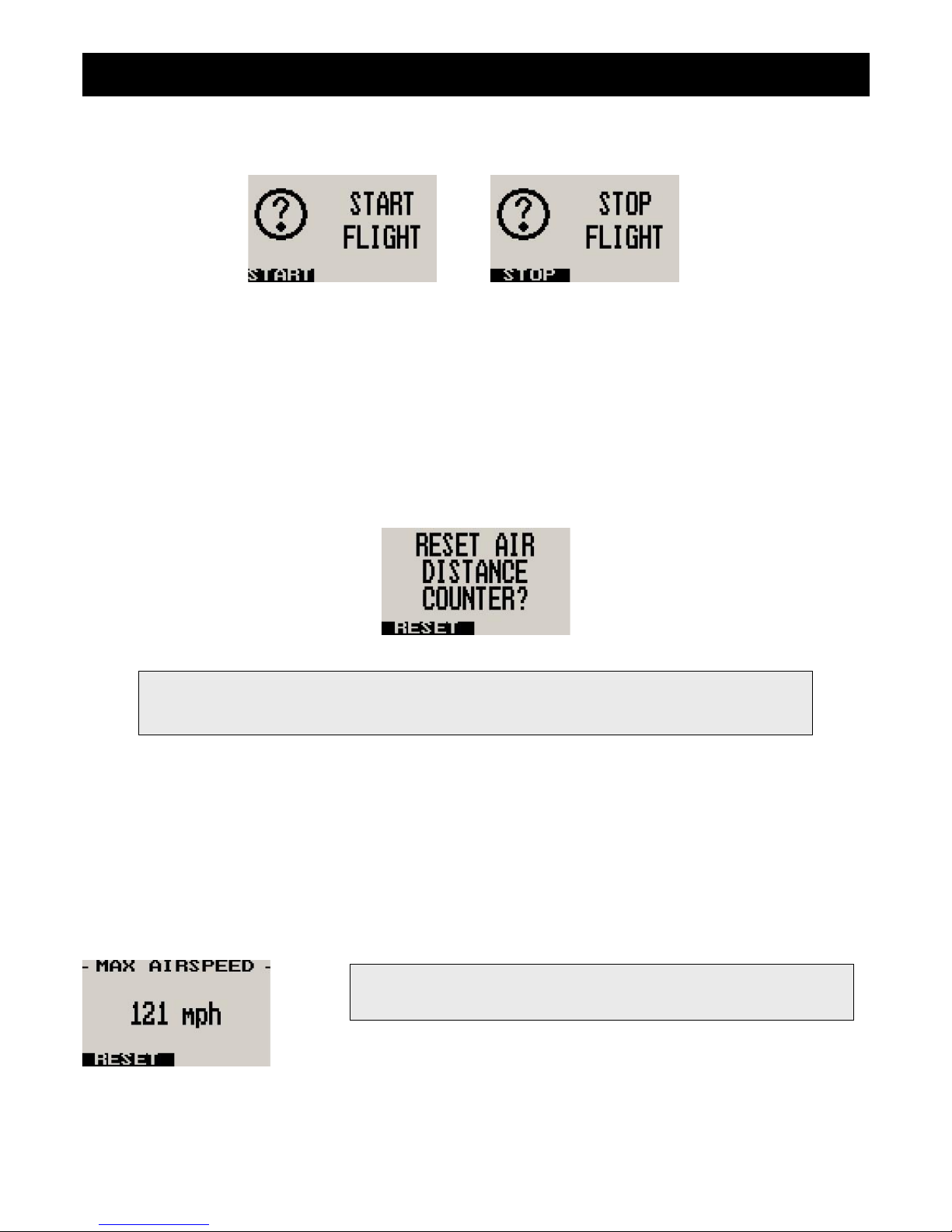
3.1 Start/Stop Flight Display
Press the F1 key during the normal display mode to manually start/stop a flight. This key is only active if the ASI-1 is
setup to select the manual flight option under the “Flight Log” setup menu.
3.2 Reset Air Distance Trip Counter Display
This display can be accessed by pressing the F2 key during the normal display mode. Pressing the F1 key will reset the
air distance trip counter to zero. Pressing any other key will cause the ASI-1 to resume to the normal display mode. The
air distance trip counter can still be reset manually even if the pilot selects the automatic resetting of the air distance trip
counter.
3.3 Maximum Airspeed Display
This display can be accessed by rotating the rotary control either clockwise or anticlockwise during the normal display
mode. Pressing the F1 key again will reset the maximum airspeed to the current airspeed. Pressing any other key will
cause the ASI-1 to resume back to the normal display mode. To avoid false recordings, the maximum airspeed function is
only activated 10 seconds after the instrument has powered up.
Note: The maximum airspeed is stored in non-volatile memory and is
recalled on power-up.
Note: The air distance trip counter measures distance flown through the air. This is not the same as
distance flown over the ground unless you are flying at sea level at zero wind speed. The air
distance shown is subject to under reading at altitude due to decreased air density.
Page 29
ASI-1 Operating Manual Page 4
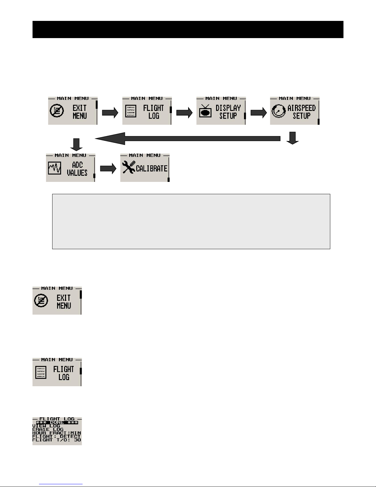
4 Menu System
Pressing the rotary control button during the normal display mode will cause the ASI-1 to enter the menu system. Use the
up/down keys or the rotary control to navigate through the menu system.
4.1 Exit Menu
Pressing the rotary control on this menu item will cause the ASI-1 to exit the menu system. All
changes made during navigation of the menu system will be saved in non-volatile memory on exiting
the menu system. If you remove power before exiting the menu the instrument will not save any
changes.
4.2 Flight Log
The ASI-1 uses the following algorithm to determine if a flight is in progress (Detect Mode): If
airspeed is greater than the preset flight take off airspeed for a duration of 60 seconds or more, a
flight is started with a logbook entry. The flight ends if airspeed falls below the preset flight take-off
airspeed for 30 seconds. During a flight the logbook cannot be viewed.
The above algorithm ensures that touch-and-goes will not result in the end of a flight and a logbook
entry. Should the instrument be switched off during a flight, this will end the flight and the log will
reflect the time until the instrument was switched off. Should the instrument be switched on again during a flight, a new
flight will start for logging purposes.
Move the highlight over the “DONE” menu item and press the rotary button to return to the main
menu
Note: (ADC Values and Calibrate Menus are only visible when powering up the unit and pressing the
Rotary Control). The text “CALIBRATE” will appear on the intro screen when entering this mode.
Warning: The Calibrate Menu is for technical personnel only. Changing any values in this menu may
cause the instrument to display incorrect information, and may require the instrument to be returned to
the factory for recalibration.
Page 30
ASI-1 Operating Manual Page 5
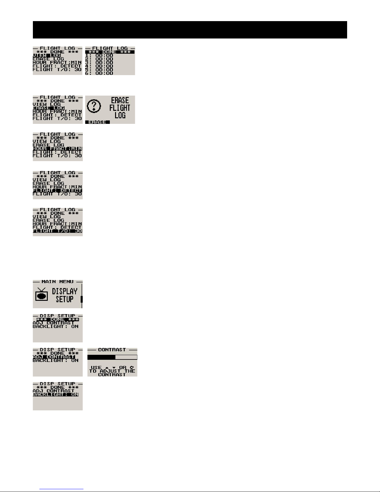
Select this function to view the flight log. The flight log contains the duration of
each of the last 24 logged flights. Duration is displayed in hours and minutes.
Use the up/down keys or the rotary control to navigate through the log. Empty
log entries are shown as “-----“.
Note: You cannot select this function while a flight is in progress.
Pressing the F1 key will erase all the flight log entries
Select if you would like the hour to be displayed in decimal fractions (0-99) or minutes (0-59).
This setting influences the current flight time display and the flight log.
Select whether you want the ASI-1 to automatically detect a flight or whether the pilot must press the
F1 key to start/stop a flight.
This menu option is only shown if the “detect” flight mode is selected. Enter the airspeed that you
want to start a flight log.
4.3 Display Setup
Move the highlight over the “DONE” menu item and press the rotary button to return to the main
menu
Select this menu option to adjust the display contrast
Select this menu option to turn the backlight on or off
Page 31
ASI-1 Operating Manual Page 6
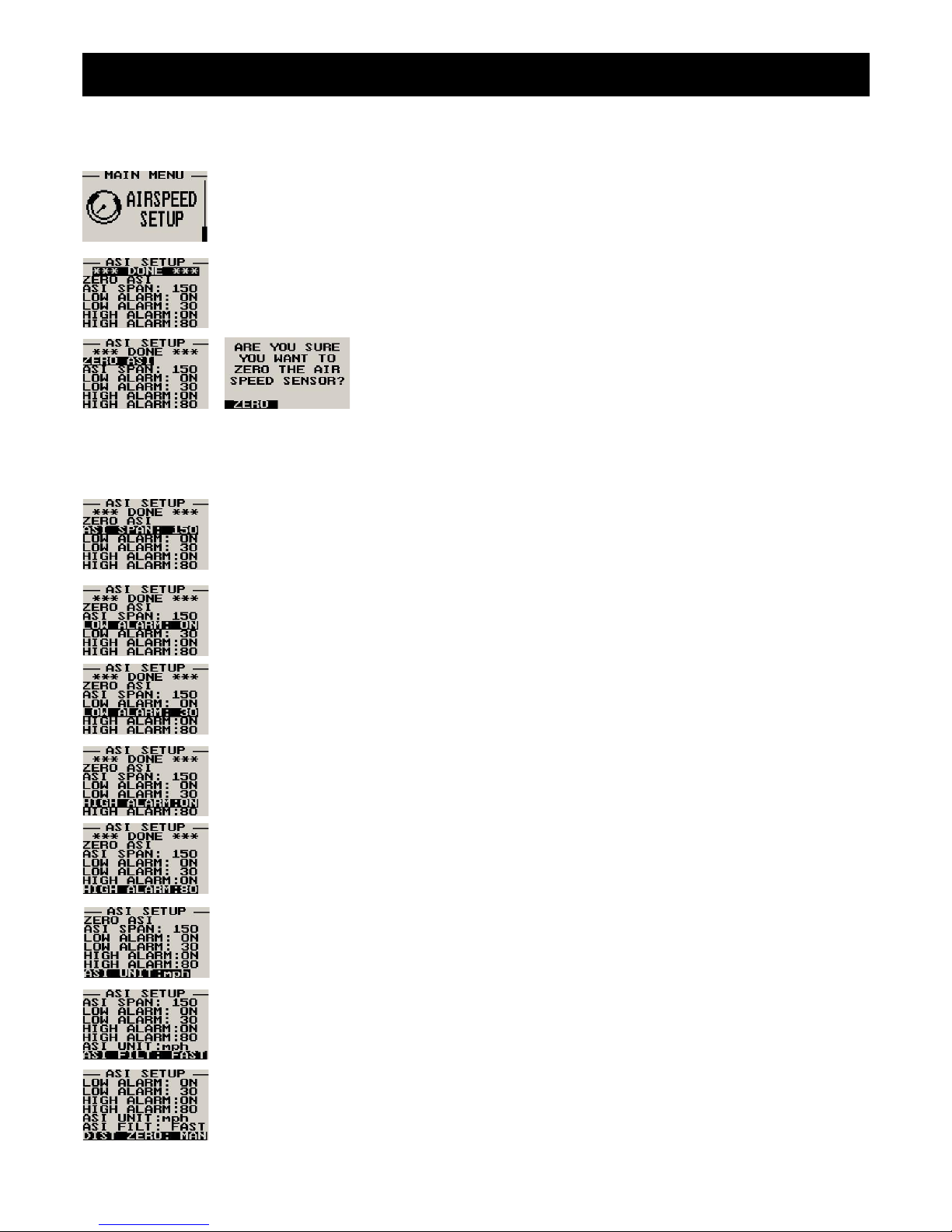
4.4 Airspeed Setup
All the airspeed parameters can be setup here
Move the highlight over this menu option and press the rotary button to return to the main menu
This setup allows your instrument to measure the zero airspeed reading of the
airspeed sensor and set a calibration value internally for this. This is
equivalent to some mechanical airspeed indicators that have an adjustment to
set the needle to zero when the aircraft is not moving. You would use this
function occasionally if you see an airspeed reading when the aircraft is at
rest. This may be caused by aging of the built in pressure sensor or related electronics. When this function is performed
make sure that there is no air flow into the pitot tube as this would result in an incorrect internal calibration.
Pressing the F1 key will zero the airspeed sensor.
Select the maximum value that you want the airspeed analog bar graph display to show. This can
give you increased display resolution.
Select whether you want the low air speed alarm to be turned on or off. The low airspeed alarm is
only activated once a flight has started.
Enter the low airspeed set-point for when the alarm must activate. Any speed below this value will
activate the alarm.
Select whether you want the high air speed alarm to be turned on or off.
Enter the high airspeed set-point for when the alarm must activate. Any speed above this value will
activate the alarm.
Select your preferred units. You can select statute miles, kilometers or nautical miles. According
to this selection your airspeed will be indicated in mph, km/h or knots.
This function can be used to select the signal filter time constant. Selections are “fast” or “slow”. This
selection influences the rate at which your ASI can change its reading. If you have an installation
that suffers from strong turbulence at the pitot tube, select “slow”. If you have a very clean airflow in
front of the pilot tube you can select “fast” which will give you a faster response to airspeed changes.
Select if you want the air-distance counter to reset automatically at the start of a flight or if you want
to reset manually only.
Note: You can reset the air distance counter at any time regardless of this setting.
Page 32
ASI-1 Operating Manual Page 7
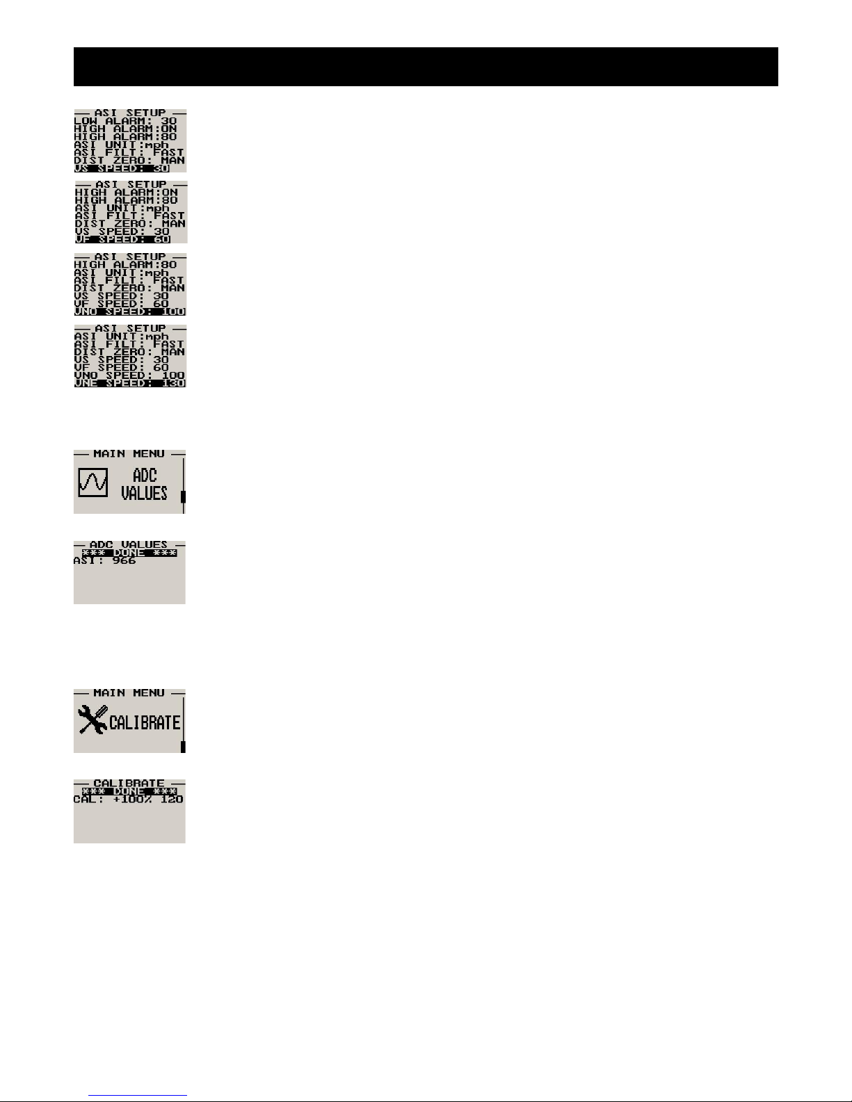
You can set up a marker on the analog airspeed display for Vs. Vs would be your stall speed or
minimum safe flying speed. You may also choose to use this marker as your approach speed.
You can set up a marker on the analog airspeed display for Vf. Vf is your maximum flap speed.
You can set up a marker on the analog airspeed display for Vno. Vno is the maximum
maneuvering speed or top end of the normal operating speed range.
You can set up a marker on the analog airspeed display for Vne. Vne is the never exceed maximum
speed.
4.5 ADC Values
Note: This menu item is for technical personnel only, and is not displayed during the normal
operation of the instrument. Please see section 4 above on how to access this menu item.
This menu displays the ADC values that have been read from the pressure sensor.
4.6 Calibrate
Note: This menu item is for technical personnel only, and is not displayed during the normal
operation of the instrument. Please see section 4 above on how to access this menu item. Consult
your local dealer or factory before entering this menu.
This function is used to calibrate your airspeed indicator. During the factory calibration a factor has
been determined and entered here that will give you accurate airspeed, provided your pitot tube is
not influenced by pressure effects caused by airflow around your airframe. The calibration is
displayed in % of the reading, you can increase or decrease the reading if required to help cancel
out under or over reading of the airspeed indicator on your aircraft. The original calibration factor has
been written onto the back of your instrument.
Page 33
ASI-1 Operating Manual Page 8
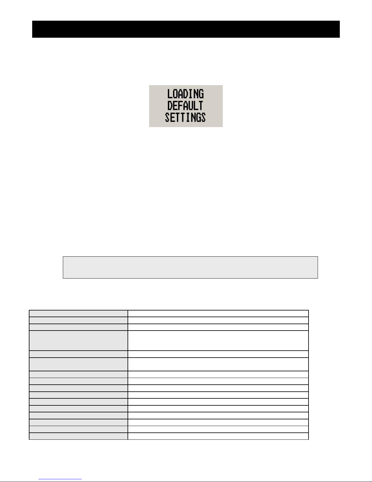
5 Loading Factory default settings
Pressing and holding the F1 and F2 key simultaneously on power up will cause the ASI-1 to load preprogrammed factory
default settings. The following screen will be displayed:
6 Operating the alarms
If the alarm is activated, the corresponding item on the display will flash. At the same time the externally available alarm
switch will close. The switch will remain closed until any button is pressed to acknowledge the alarm or until the
condition(s) that activated the alarm no longer exist. The alarm output can be used to switch an external alarm indicator.
The external alarm switch is an open collector transistor switch to ground with a maximum rating of 0.5A DC. It is possible
to wire the alarm contacts of several Stratomaster instruments in parallel should this be desired. To avoid false activation
of the alarms, the alarm function is only active 10 seconds after the instrument has powered up.
7 Cleaning
The unit should not be cleaned with any abrasive substances. The screen is very sensitive to certain cleaning materials
and should only be cleaned using a clean, damp cloth.
8 Specifications
Operating Temperature Range -10ºC to 50ºC (14ºF to 122ºF)
Storage Temperature Range -20ºC to 80ºC (-4ºF to 176ºF)
Humidity <85% non-condensing
Power Supply
8 to 30Vdc SMPS (switch mode power supply) with built in 33V over
voltage and reverse voltage protection
Current Consumption Approx. 45mA @ 13.8V (backlight on) 15mA @13.8V (backlight off)
Display
114x64 graphic LCD display. Contrast and backlight is user
configurable, green/yellow backlight
ADC 12bit over sampled successive approximation
Dimensions see Infinity series dimensional drawing
Enclosure 2 1/4” ABS, black in color, front or rear mounting
Weight Approx. 116 grams
Alarm contact current rating Open collector transistor switch to ground. Maximum rating 0.5A DC
Non-volatile memory storage 100000 write cycles
Airspeed range 16mph to 250mph
Airspeed resolution 1 mph
Measurement accuracy +/-1% at 85mph nominal
Airtalk protocol 19200 baud, 8 data bits, no parity, 1 stop bit (TTL voltage levels)
Warning: The ASI-1 is not waterproof, serious damage could occur if the unit is exposed to
water and/or spray jets.
Page 34
ASI-1 Operating Manual Page 9
9 Installation
Connect a pitot tube to the “pressure port” and if required connect the static port. Pitot tubes are found in a large variety at
your aircraft parts shop, in mail order catalogs or you can make your own. Contrary to popular belief, pitot tubes are not
carefully designed and calibrated but are simple orifices or tubes that get pointed in the direction that you are flying. The
forward movement of the aircraft causes air to dam inside the pitot tube. This increases the pressure inside the tube. Most
small aircraft such as ultralights or microlights do not require a connection to a static port. In these cases, simply leave the
static port open. Ensure however that the static port does not receive pressurized air due to the forward movement of the
aircraft. Be especially critical of your pod or panel if you do not use a static port. Any build up of a pressure differential due
to ram air or suction can lead to large errors of the indicated airspeed. Static ports are usually mounted at a strategic
position on the rear side of the aircraft fuselage for faster, pressurized aircraft. Suitable pitot tubes can be made from a
short piece of hollow aluminum or copper piping. Length and diameter are not important. Ensure that the front of the pitot
tube has a suitable chamfer if you use thick walled tubing or you may introduce a speed reading error if you have a faster
aircraft.
Example cross-section of thick walled pitot tube.
Suitable connection hose for both pitot tube and static port can be obtained from a hardware store or even a pet shop.
Good quality tubing is often used for fish tanks and it has just the right diameter.
Please note that this kind of tubing is not advised for pressurized aircraft. In this case you would need to obtain aircraft
grade tubing of suitable diameter. You would also have to use hose clamps to fasten the hose onto the ASI-1 pitot and
static ports. The ASI-1 allows you to calibrate the airspeed reading. This is done under the “Calibrate” menu item. The
main reason for this is to be able to remove errors introduced due to the airflow around your aircraft which may have an
effect on your pitot tube pressure.
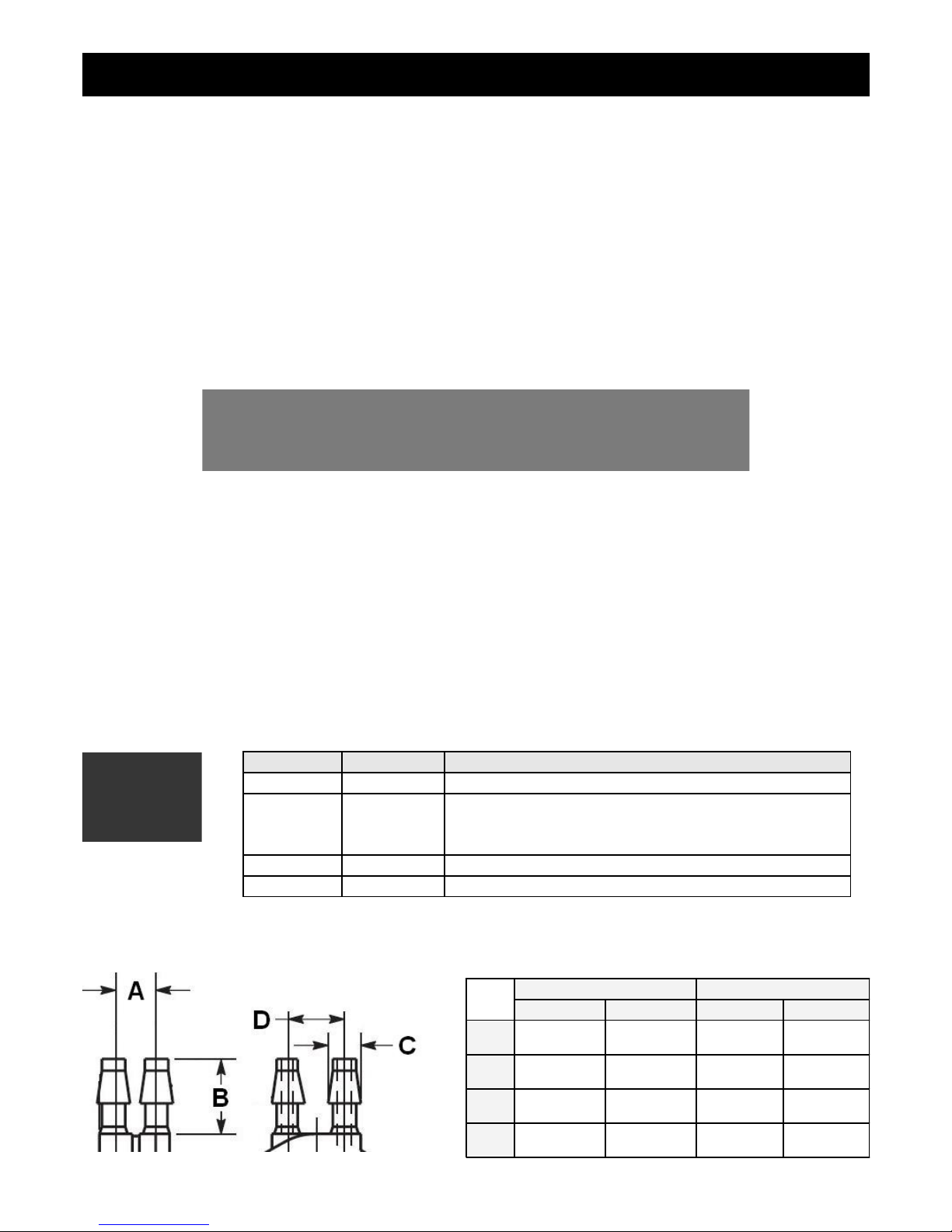
9.1 ASI-1 DB9 Cable connections
9.2 Pressure Port Dimensions
DB 9 Pin Color Function
1 Black Ground
4 NC Airtalk communication
Used for firmware upgrading and interfacing
to the FF-1/SP-X (Airtalk speed message)
6 Red 8-30Vdc power
9 White Alarm Output
Inches Millimeters
Min Max Min Max
A
0.248 0.278 6.30 7.06
B
0.420 0.440 10.67 11.18
C
0.182 0.194 4.62 4.93
D
0.310 0.330 7.87 8.38
Page 35
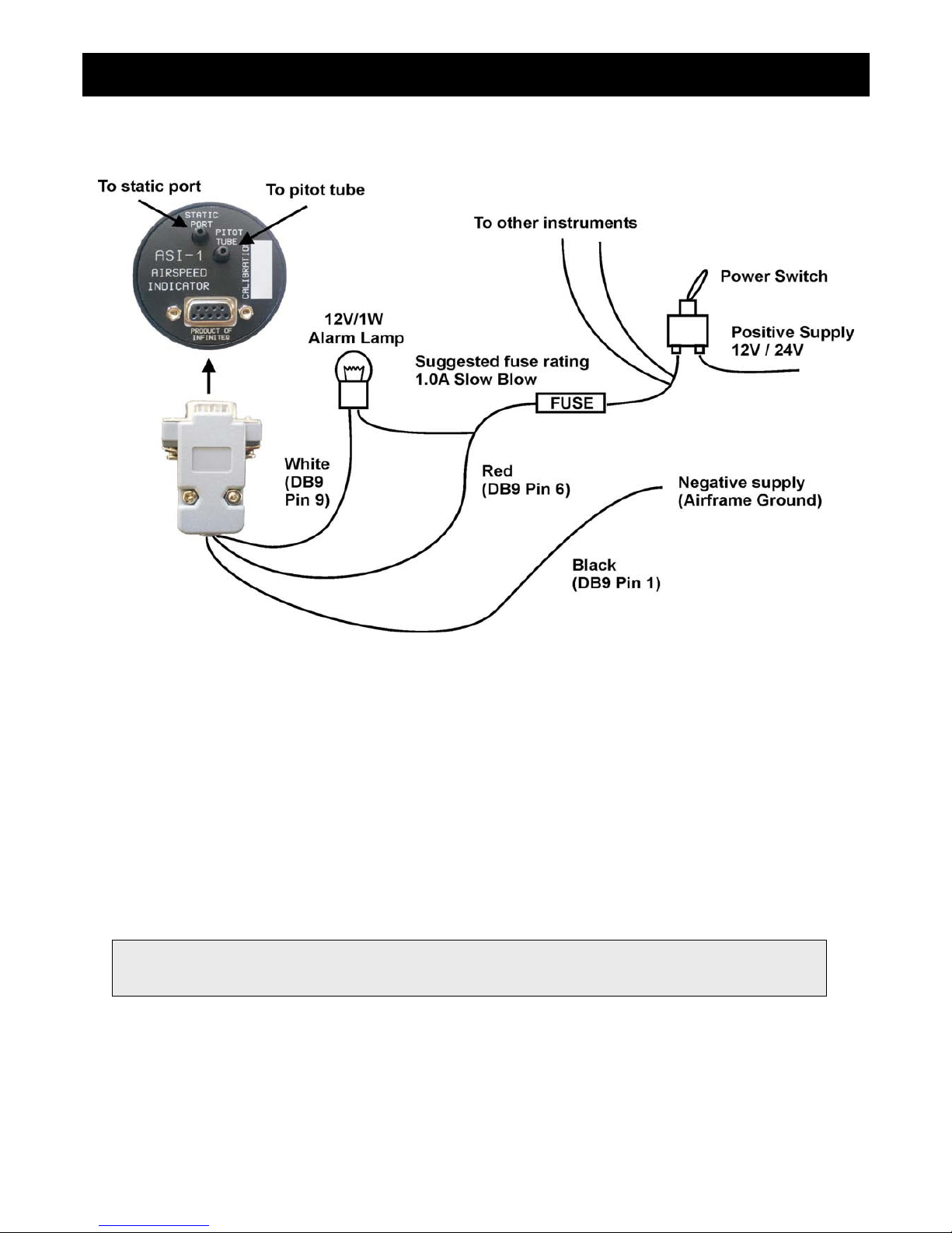
ASI-1 Operating Manual Page 10
9.3 Connection Diagram
The use of an external 1A fuse is recommended. Connect the supply terminals to your aircrafts power supply. The ASI-1
can be used on both 12V and 24V without the use of any pre-regulators. Ensure that the supply voltage will not drop
below 8V during operation as this may result in incorrect voltage and or current readings.
10 Warranty
This product carries a warranty for a period of one year from date of purchase against faulty workmanship or defective
materials, provided there is no evidence that the unit has been mishandled or misused. Warranty is limited to the
replacement of faulty components and includes the cost of labour. Shipping costs are for the account of the purchaser.
Damage as a result of applying excessive pressure to the pressure ports are excluded from warranty.
Note: Product warranty excludes damages caused by unprotected, unsuitable or incorrectly wired
electrical supplies and/or sensors, and damage caused by inductive loads.
Page 36

ASI-1 Operating Manual Page 11
11 Disclaimer
Operation of this instrument is the sole responsibility of the purchaser of the unit. The user must make themselves familiar
with the operation of this instrument and the effect of any possible failure or malfunction.
This instrument is not certified by the FAA. Fitting of this instrument to certified aircraft is subject to the rules and
conditions pertaining to such in your country. Please check with your local aviation authorities if in doubt. This instrument
is intended for ultralight, microlight, homebuilt and experimental aircraft. Operation of this instrument is the sole
responsibility of the pilot in command (PIC) of the aircraft. This person must be proficient and carry a valid and relevant
pilot’s license. This person has to make themselves familiar with the operation of this instrument and the effect of any
possible failure or malfunction. Under no circumstances does the manufacturer condone usage of this instrument for IFR
flights.
Other instruments in the Stratomaster Infinity series
ALT-1 Precision encoding altimeter and vertical speed indicator
ALT-2 Precision encoding altimeter and vertical speed indicator with a serial RS232
transponder output
ASI-1 Airspeed indicator (ASI) with automatic flight log
ASX-1 Encoding aviation altimeter with serial output and airspeed indicator (ASI)
AV-1 Artificial horizon and magnetic compass indicator
BAT-1 Battery voltage and current monitor
E-3 Universal engine monitor
FF-1 Fuel Computer (single or dual fuel tanks)
GF-1 +-10G tilt compensated dual range G-force meter
MAP-1 Manifold pressure and RPM Indicator
RV-1 Universal engine RPM and rotor RPM Indicator
RV-2 Universal turbine RPM / RPM factor display
RTC-2 Aviation real time clock (RTC) and outside air temperature (OAT) display
TC-1 4-Channel thermocouple indicator
TP-1 Universal temperature and pressure gauge
The manufacturer reserves the right to alter any specification without notice.
Page 37
Introduction
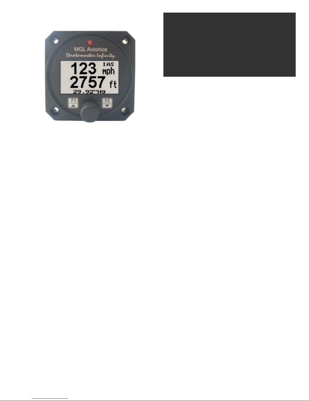
The ASX-1 altimeter/airspeed combo is a 2 1/4” instrument based on a precision altimeter and a wide range, sensitive
airspeed indicator. The altimeter conforms to ANSI standard atmosphere rules from –1000 ft up to a maximum of 30 000
ft.The altimeter includes an encoding serial output that, when used in combination with MGL Avionics CNV-AT, provides a
parallel Gillham code interface for transponders. The altimeter can display altitude in feet or meters. Local pressure can
be set in millibars or inches of Mercury.
The airspeed indicator can show air speeds from 16 to 250 mph and is well suited for use in slow aircraft due to very good
sensitivity and linearity at low air speeds. The airspeed indicator as well as altimeter can interface to a static port and the
airspeed indicator is based on a standard aviation pitot tube. The airspeed indicator can be set to indicate speeds in
statute miles per hour (mph), kilometers per hour (km/h) or nautical miles per hour (knots) with the air-distance being
displayed in corresponding units. The airspeed sensitivity can be calibrated by the user to cater for errors caused by pitot
tube placement. The ASX-1 also outputs airspeed information via the airtalk protocol for interfacing to the Infinity FF-1 /
Velocity FF-3 (fuel flow computer for single or dual fuel tanks) and the SP-X (AHRS) instruments.
In addition the ASX-1 provides a 24 entry automatic flight log that stores the duration of each of the last 24 flights, an airdistance trip counter and a current flight timer. The ASX-1 is the ideal instrument for installations where panel space is
limited.
1 Features
• Precision altimeter from –1000 ft up to a maximum of 30 000 ft (-304 to 9144m)
• Provides a parallel Gillham code interface for transponders when used in combination with the MGL
Avionics CNV-AT
• The altimeter can display altitude in feet or meters. Local pressure can be set in millibars or inches of
Mercury
• Airspeed ranges from 16 to 250mph and is well suited to slow aircraft due to very good sensitivity and
linearity at low air speeds. Airspeed can be displayed as IAS or a calculation based TAS
• Includes a 24 entry automatic flight log
• Includes an air-distance trip counter and a flight timer
• Airspeed units can be in miles per hour (mph), kilometer per hour (km/h) or nautical miles per hour (knots)
• Contains a programmable low/high airspeed alarm
• Records maximum airspeed and altitude reached in permanent memory
• Standard 2 1/4” aircraft enclosure (can be front or rear mounted)
• Rotary control plus 2 independent buttons for easy menu navigation and user input
• Alarm output as well as a red LED illuminates when the alarm has been activated
• Large backlit graphic LCD with adjustable contrast
• Wide input supply voltage range of 8 to 30V DC with built in voltage reversal and over voltage protection
for harsh electrical environments
• Light weight design
• Field upgradeable firmware
• 1 year limited warranty
ASX-1
Encoding aviation altimeter with
serial output and airspeed Indicator
(ASI)
Operating Manual – English 1.06
Page 38
ASX-1 Operating Manual Page 2
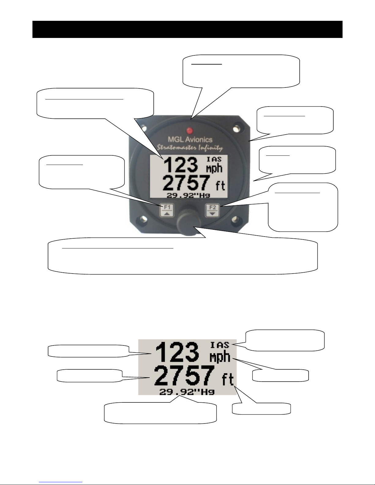
2 ASX-1 Layout
3 Main Display
Backlit Graphic LCD Display:
Contrast and backlight can be adjusted
in the menu system
Harness:
Harness connects to
power
Up/F1 Button:
Up button in menu system
Start/Stop flight in normal
mode
Down/F2 Button:
Down button in menu
system
Flight time and air
distance display in
normal mode
Rotary Control (up/down) & Enter Button:
Press the rotary control during normal mode to access the menu system. Rotate anti/clockwise
for up/down menu scrolling. During normal mode rotating the rotary control will adjust the local
pressure setting. Local pressure can be set in either mB or in “Hg.
Pressure Ports:
Pressure ports connect
to static and pitot tubes
LED Alarm:
The red LED will illuminate if the
airspeed alarm set points has been
exceeded
Airspeed units
Altitude units
Digital airspeed display
Digital altimeter
IAS: Indicated airspeed
TAS: True airspeed
Local pressure readout (either in
millibar or in inches of Mercury)
Page 39
ASX-1 Operating Manual Page 3
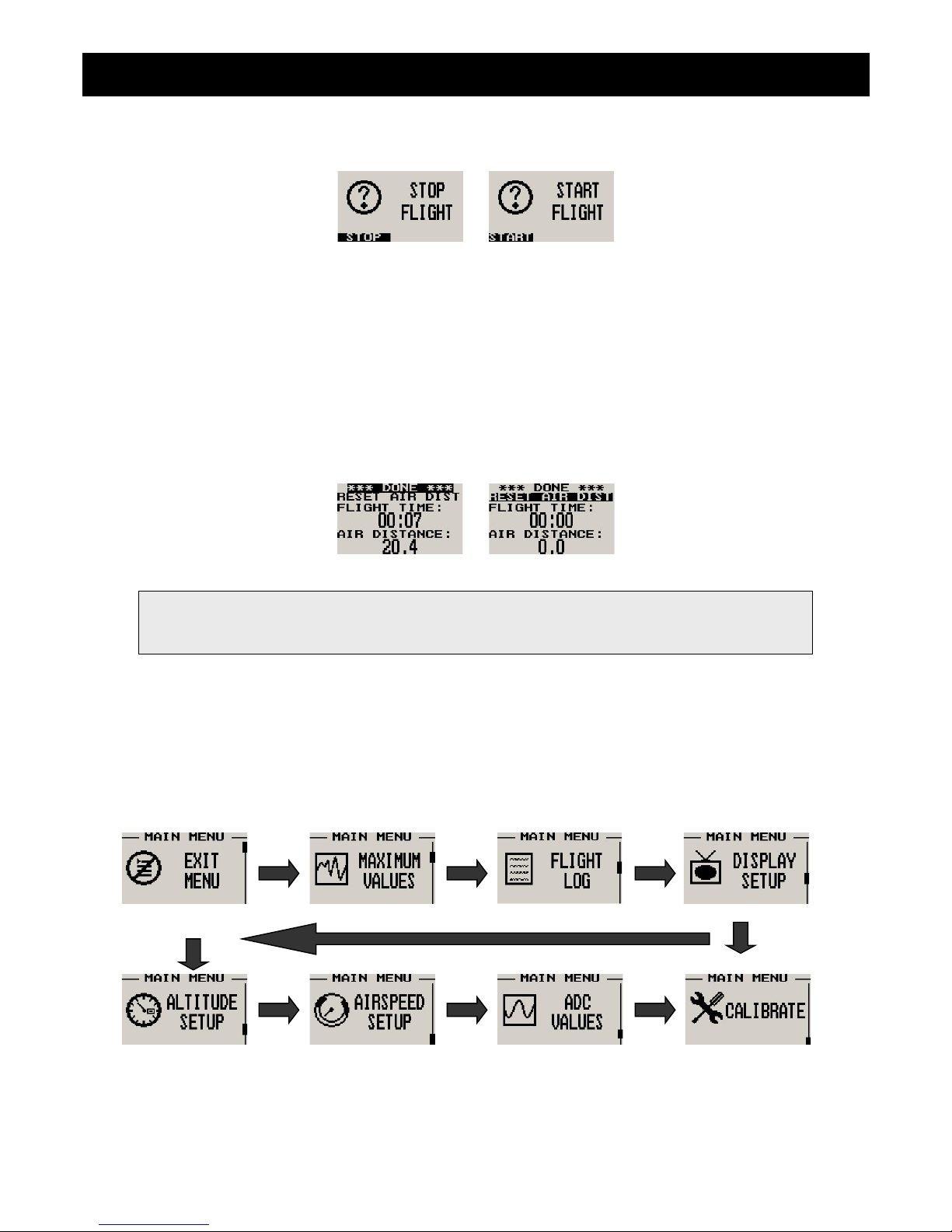
3.1 Start/Stop Flight display
Press the F1 key during the normal display mode to manually start/stop a flight. This key is only active if the ASX-1 is
setup to select the manual flight option under the log book setup menu.
3.2 Flight time and air distance display
This display can be accessed by pressing the F2 key during the normal display mode. Use the up/down keys or the rotary
control to select “reset air dist” to reset the air distance counter. The flight time is automatically reset when a new flight is
started. The air distance trip counter can still be reset manually even if the pilot selects the automatic resetting of the air
distance trip counter.
4 Menu System
Pressing the rotary control button during the normal display mode will cause the ASX-1 to enter the menu system. Use
the up/ down keys or the rotary control to navigate through the menu system.
Note: The air distance trip counter measures distance flown through the air. This is not the same as
distance flown over the ground unless you are flying at sea level at zero wind speed. The air
distance shown is subject to under reading at altitude due to decreased air density.
Page 40
ASX-1 Operating Manual Page 4
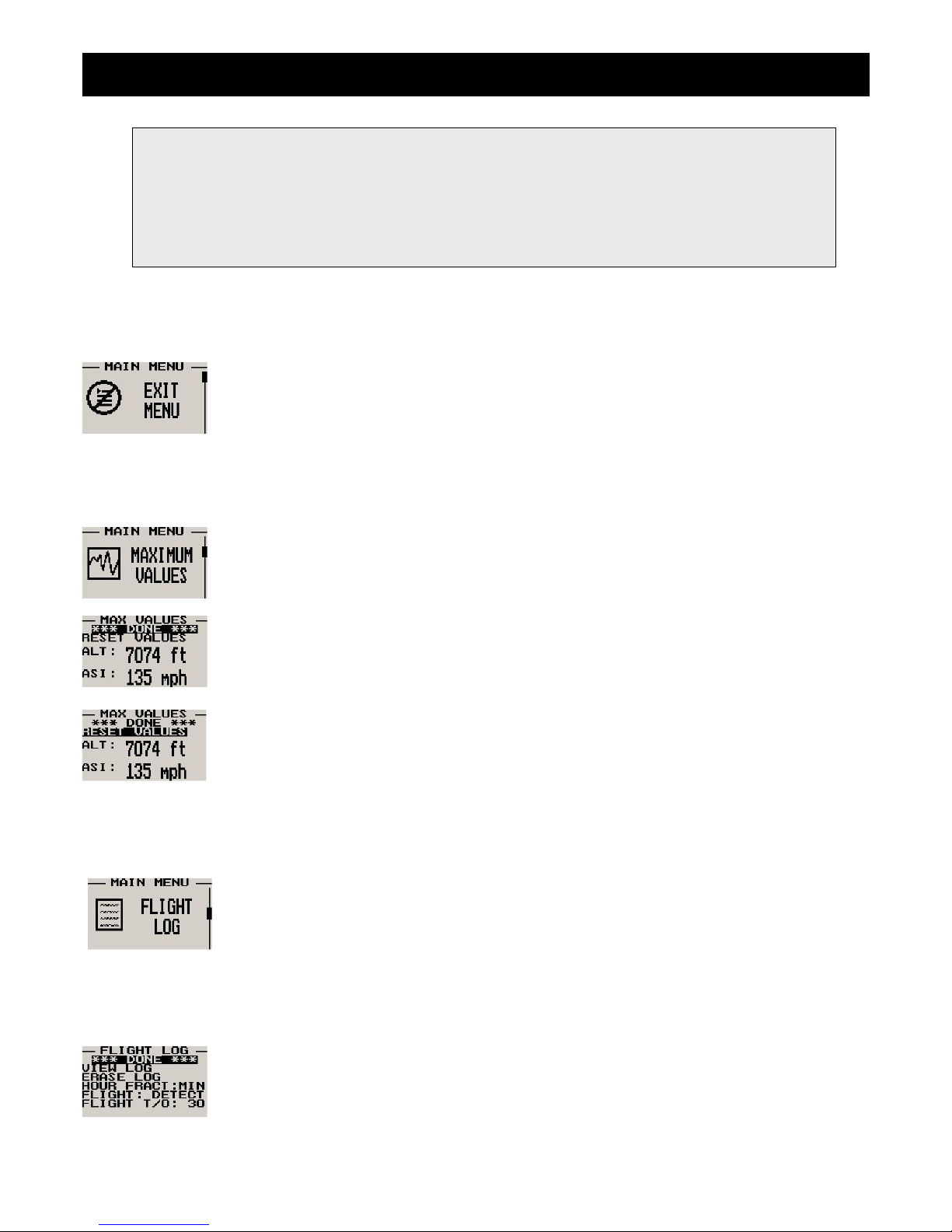
4.1 Exit Menu
Pressing the rotary control on this menu item will cause the ASX-1 to exit the menu system. All
changes made during navigation of menu system will be saved in non-volatile memory on exiting the
menu system. If you remove power before exiting the menu the instrument will not save any
changes.
4.2 Maximum Values
To avoid false recordings, the maximum values function is only activated 10 seconds after the
instrument has powered up.
Move the highlight over the “DONE” menu item and press the rotary button to return to the main
menu.
Move the highlight over this menu item and press the rotary button to reset the maximum altitude
and airspeed values to the current values.
4.3 Flight Log
The ASX-1 uses the following algorithm to determine if a flight is in progress (Detect Mode):
If airspeed is greater than the preset flight take off airspeed for the duration of 60 seconds or more,
a flight is started with a logbook entry. The flight ends if airspeed falls below the preset flight take off
airspeed for 30 continuous seconds. During a flight the logbook cannot be viewed.
The above algorithm ensures that touch-and-goes will not result in the end of a flight and a logbook
entry. Should the instrument be switched off during a flight, this will end the flight and the log will reflect the time until the
instrument was switched off. Should the instrument be switched on again during a flight, a new flight will start for logging
purposes.
Move the highlight over this menu item and press the rotary button to return to the main menu.
Note: (ADC Values and Calibrate Menus are only visible when powering up the unit and pressing the
Rotary Control). The text “CALIBRATE” will appear on the intro screen when entering this mode.
Warning: The Calibrate Menu is for technical personnel only. Changing any values in this menu may
cause the instrument to display incorrect information, and may require the instrument to be returned to
the factory for recalibration.
Page 41
ASX-1 Operating Manual Page 5
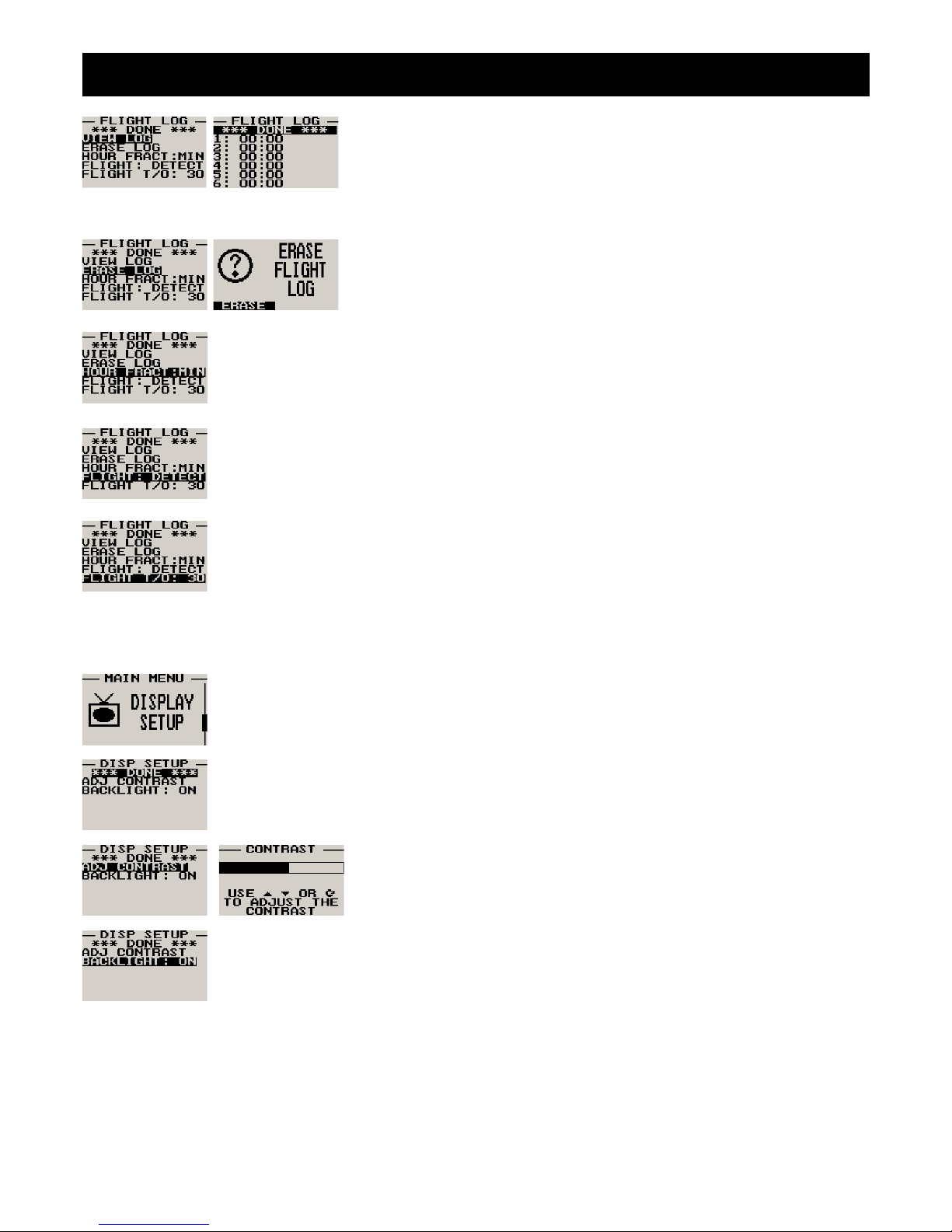
Select this function to view the flight log. The flight log contains the duration of
each of the last 24 logged flights. Duration is displayed in hours and minutes.
Eight flights are displayed at a time, Use the up/down or the rotary control to
navigate through the log. Empty log entries are shown as “--:--“.
Note: You cannot view the flight log while a flight is in progress.
Pressing the F1 key will erase all the flight log entries.
Select if you would like the hour to be displayed in decimal fractions (0-99) or minutes (0-59).
This setting influences the current flight time display and the flight log.
Select whether you want the ASX-1 to automatically detect a flight or whether the pilot must press
the F1 key to start/stop a flight.
This menu item is only shown if the “detect” flight mode is selected. Enter the airspeed that you want
a flight log entry to start.
4.4 Display Setup
Move the highlight over the “DONE” menu item and press the rotary button to return to the main
menu.
Select this menu option to adjust the display contrast.
Select this menu option to turn the backlight on and off.
Page 42
ASX-1 Operating Manual Page 6
4.5 Altitude Setup
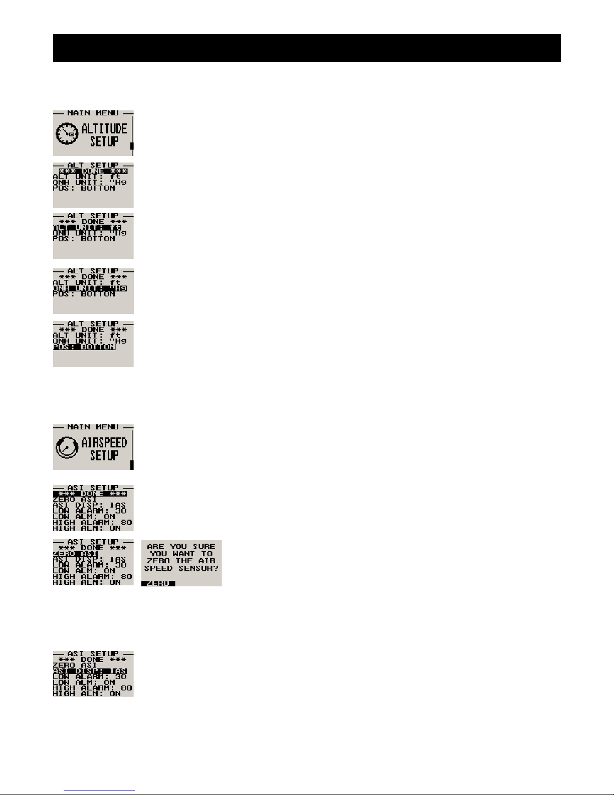
Move the highlight over this menu item and press the rotary button to return to the main menu.
Select if you want your altitude readout in feet (ft) or meters (m).
Select if you want your local pressure readout in millibars (mB) or inches of Mercury (“Hg).
Select whether you want the altitude display on the top or on the bottom of the main display.
4.6 Airspeed Setup
All the airspeed parameters can be setup here.
Move the highlight over the “DONE” menu item and press the rotary button to return to the main
menu.
This setup allows your instrument to measure the zero airspeed reading of the
airspeed sensor and set a calibration value internally for this. This is equivalent
to some mechanical airspeed indicators that have an adjustment to set the
needle to zero when the aircraft is not moving. You would use this function
occasionally if you see an airspeed reading when the aircraft is at rest. This
may be caused by aging of the built in pressure sensor or related electronics. When you perform this function, make sure
that no wind is blowing into the pitot tube as this would result in an incorrect internal calibration.
Pressing the F1 key will zero the airspeed sensor.
Enter whether you want the airspeed to display true airspeed (TAS) or indicated airspeed (IAS).
Please see section 6 below for more information on true airspeed (TAS).
Page 43
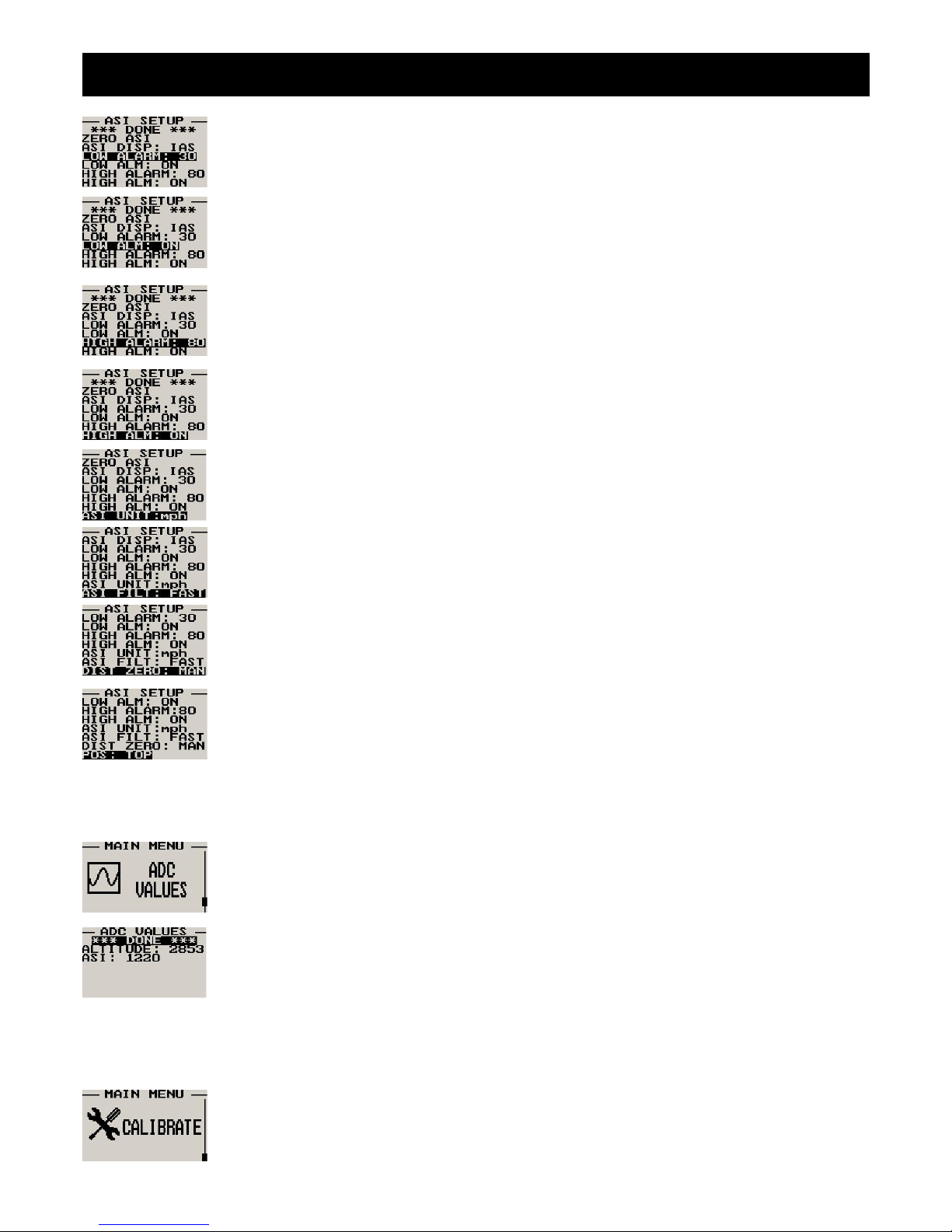
ASX-1 Operating Manual Page 7
Enter the low airspeed set-point for when the alarm must activate. Any speed below this value will
activate the alarm.
Select whether you want the low air speed alarm to be turned on or off. The low airspeed alarm is
only activated once a flight has started.
Enter the high airspeed set-point for when the alarm must activate. Any speed above this value will
activate the alarm.
Select whether you want the high air speed alarm to be turned on or off.
Select the ASI unit of preference. You can select statute miles, kilometers or nautical miles.
According to this selection your airspeed will be indicated in mph, km/h or knots.
This function can be used to select the signal filter time constant. Selections are “fast” or “slow”. This
selection influences the rate at which your ASI can change its reading. If you have an installation
that suffers from strong turbulence at the pitot tube, select “slow”. If you have a very clean airflow in
front of the pilot tube you can select “fast” which will give you a faster response to airspeed
changes.
Select if you want the air-distance counter to reset automatically at the start of a flight or if you want
to reset it manually only.
Note: You can reset the air distance counter at any time regardless of this setting.
Select whether you want the airspeed display on the top or on the bottom of the main display.
4.7 ADC Values
Note: This menu item is for technical personnel only, and is not displayed during the normal
operation of the instrument. Please see section 4 above on how to access this menu item.
This menu displays the ADC values that have been read from the pressure sensors.
4.8 Calibrate
Note: This menu item is for technical personnel only, and is not displayed during the normal
operation of the instrument. Please see section 4 above on how to access this menu item. Consult
your local dealer or factory before entering this menu.
Page 44
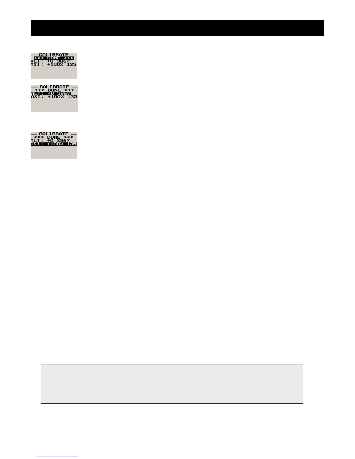
ASX-1 Operating Manual Page 8
Move the highlight over this menu item and press the rotary button to return to the main menu.
On the back of the ASX-1 you will find the calibration number that has been determined to result in
the most accurate reading of your altimeter. This is the value that should be entered here. Should
you have access to an accurate reference you may use this function to calibrate your altimeter.
Before you do this, ensure that you have your local pressure set to coincide with a calibrated and
certified reference. Your altimeter has been calibrated by the factory to an accuracy of +/- one mB
or approximately +/- 30 ft (10m).
This function is used to calibrate your airspeed indicator. During the factory calibration a factor has
been determined and entered here that will give you accurate airspeed provided your pitot tube is
not influenced by pressure effects caused by airflow around your airframe. The calibration works in
% of the reading and you can increase or decrease the reading if required to help cancel out under
or over reading of the airspeed indicator on your aircraft. The original calibration factor has been
written onto the back of your instrument.
5 Altitude Encoder
To use the ASX-1 as an encoding altimeter an Airtalk to parallel Gillham code output encoder such as the MGL Avionics
CNV-AT must be used. This converter takes the Airtalk serial string that is outputted by the ASX-1 and converts it to a
parallel Gillham code suitable for aircraft transponders. Please see the CNV-AT operating manual for more information.
6 True airspeed (TAS)
TAS is indicated airspeed corrected for air density. As air density decreases with altitude, an airspeed indicator will under read
at altitude. This error can be appreciable, for example at an altitude of 5 000 ft (1 524 m) errors of 5% to 10% are possible
depending on local weather and temperature conditions. As you increase the altitude the error gets larger quickly. Setting your
instrument to read TAS will correct for this error based on the pressure altitude reading, taking your current QNH setting into
account. The result of this is an airspeed reading that can be as accurate as 1%, depending mainly on the errors introduced by
the airflow around your aircraft and pitot tube.
How is TAS calculated? Often pilots ignore the effect of temperature and only take altitude into account when converting
ASI to TAS. For practical purposes this is quite accurate and gives a good reflection on your true airspeed. Keeping in
mind that ASI measurement is subject to errors caused by airflow around your aircraft, there seems little point in taking
this calculation to absolute resolution. Again, we have decided to use a formulae often used by pilots. This way the
instrument reading will agree with what pilots are used to.
Based on Worthington’s 13th edition page 349:
Add 1.75% of indicated airspeed (IAS) per 1000 ft (304.9 m) increase in altitude above sea level.
We assume here that IAS = RAS (rectified air speed).
Warning when using TAS: You aircraft’s stall, rotation and approach speeds are based on sea-level ASI
indication. Should you use TAS indication at altitude you must correct for the reduced ambient pressure effects
on the control and flight surfaces of your aircraft. Should you fail to do so you will endanger your flight by flying
to slowly for prevailing conditions. Always use the ASI indication to determine your rotation or approach
speeds.
Page 45
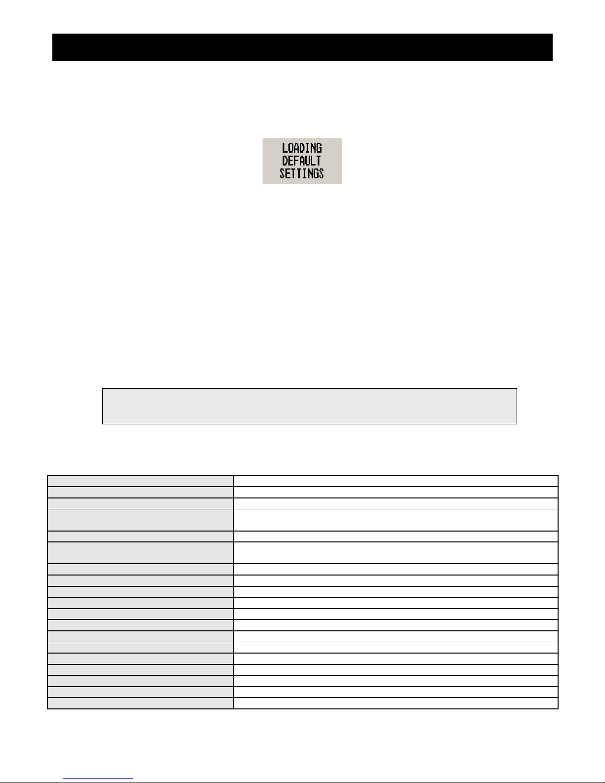
ASX-1 Operating Manual Page 9
7 Loading factory default settings
Pressing and holding the F1 and F2 simultaneously on power up will cause the ASX-1 to load preprogrammed factory
default settings. The following screen will be displayed:
8 Operating the alarms
If the alarm is activated, the corresponding item on the display will flash. At the same time the externally available alarm
switch will close. The switch will remain closed until any button is pressed to acknowledge the alarm or until the
condition(s) that activated the alarm no longer exist. The alarm output can be used to switch an external alarm indicator.
The external alarm switch is an open collector transistor switch to ground with a maximum rating of 0.5A DC. It is possible
to wire the alarm contacts of several Stratomaster instruments in parallel should this be desired. To avoid false activation
of the alarms, the alarm function is only active 10 seconds after the instrument has powered up.
9 Cleaning
The unit should not be cleaned with any abrasive substances. The screen is very sensitive to certain cleaning materials
and should only be cleaned using a clean, damp cloth.
10 ASX-1 Specifications
Operating Temperature Range -10ºC to 50ºC (14ºF to 122ºF)
Storage Temperature Range -20ºC to 80ºC (-4ºF to 176ºF)
Humidity <85% non-condensing
Power Supply
8 to 30Vdc SMPS (switch mode power supply) with built in 33V over voltage
and reverse voltage protection
Current Consumption Approx. 50mA @ 13.8V (backlight on) 16mA @13.8V (backlight off)
Display
114x64 graphic LCD display. Contrast and backlight is user configurable,
green/yellow backlight
ADC 12bit over sampled successive approximation
Dimensions see Infinity series dimensional drawing
Enclosure 2 1/4” ABS, black in color, front or rear mounting
Weight Approx. 120 grams
Alarm contact current rating Open collector transistor switch to ground. Maximum rating 0.5A DC
Non-volatile memory storage 100000 write cycles
Altimeter range -1000ft to 30 000ft (-304m to 9144m)
Altimeter resolution 1ft/1m
Measurement accuracy +/- 1mB, +/- 30ft at sea level
Airspeed range 16mph to 250mph
Airspeed resolution 1 mph
Measurement accuracy +/-1% at 85mph nominal
Airtalk protocol 19200 baud, 8 data bits, no parity, 1 stop bit (TTL voltage levels)
Warning: The ASX-1 is not waterproof, serious damage could occur if the unit is exposed to
water and/or spray jets.
Page 46
ASX-1 Operating Manual Page 10
11 Installation
Connect the static port to a suitable static air pressure line. If you have a slow aircraft or an aircraft were the internal cabin
pressure does not change during flight and is equivalent to the outside air pressure you may find that it is not required to
connect a static port. For installations in typical ultralight aircraft pods, be aware of possible pressure changes inside the
pod during flight caused by ram air or suction effects. This may lead to a false indication of altitude and/or airspeed. Often
these effects are dependent on the current angle of attack of the airflow around your pod. You will need to install a
suitable static port in these cases. Connect your pitot tube to the “pressure port”. Pitot tubes are found in a large variety at
your aircraft parts shop, in mail order catalogs or you can make your own. Contrary to popular belief, pitot tubes are not
carefully designed and calibrated, but are simple orifices or tubes that get pointed in the direction that you are flying. The
forward movement of the aircraft causes air to dam inside the pitot tube. This increases the pressure inside the tube. Most
small aircraft such as ultralights or microlights do not require a connection to a static port. In these cases, simply leave the
static port open. Ensure however that the static port does not receive pressurized air due to the forward movement of the
aircraft. Be especially critical of your pod or panel if you do not use a static port. Any build up of a pressure differential due
to ram air or suction can lead to large errors of the indicated airspeed. Static ports are usually mounted at a strategic
position on the rear side of the aircraft fuselage for faster, pressurized aircraft. Suitable pitot tubes can be made from a
short piece of hollow aluminium or copper piping. Length and diameter are not important. Ensure that the front of the pitot
tube has a suitable chamfer if you use thick walled tubing or you may introduce a speed reading error if you have a faster
aircraft.
Example cross-section of thick walled pitot tube.
Suitable connection hose for both pitot tube and static port can be obtained from a hardware store or even a pet shop.
Good quality tubing is often used for fish tanks and it has just the right diameter. Please note that this kind of tubing is not
advised for pressurized aircraft. In this case you would need to obtain aircraft grade tubing of suitable diameter. You
would also have to use hose clamps to fasten the hose onto the ASX-1 pitot and static ports. The ASX-1 allows you to
calibrate the airspeed reading. This is done in the “Calibrate” menu item. The main reason for this is to be able to remove
errors introduced due to the airflow around your aircraft which may have an effect of your pitot tube pressure.
11.1 ASX-1 DB9 Cable connections
DB 9 Pin Color Function
1 Black Ground
4 RCA
(Inner
cable)
Airtalk communication
Used for firmware upgrading and
interfacing to the FF-1/SP-X (Airtalk speed
message) or the CNV-AT (Airtalk to
parallel Gillham code output encoder)
6 Red 8-30Vdc power
9 White Alarm Output
Page 47
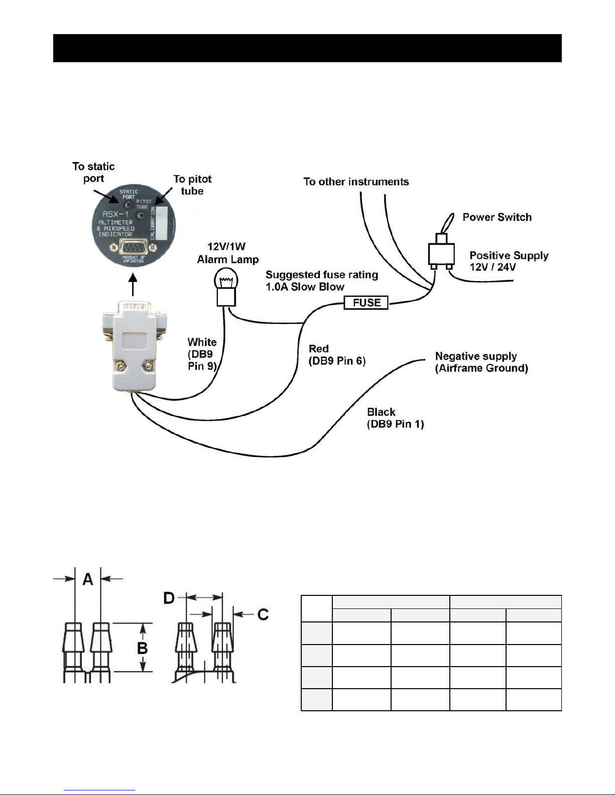
ASX-1 Operating Manual Page 11
11.2 Connection Diagram
Connect static port to suitable static line on the aircraft. Note: Leaving this port unconnected may lead to airspeed and
altitude errors as cabin pressure changes due to airflow or other factors. Connect the pressure port to a pitot tube. The
location of the pitot tube should be chosen so it is exposed to clean, undisturbed airflow at the same speed as the aircraft
if flying. Small errors related to location may be calibrated out using the ASI calibration function.
The use of an external 1A fuse is recommended. Connect the supply terminals to your aircrafts power supply. The ASI-1
can be used on both 12V and 24V without the use of any pre-regulators. Ensure that the supply voltage will not drop
below 8V during operation as this may result in incorrect voltage and or current readings.
11.3 Pressure Port Dimensions
Inches Millimeters
Min Max Min Max
A
0.248 0.278 6.30 7.06
B
0.420 0.440 10.67 11.18
C
0.182 0.194 4.62 4.93
D
0.310 0.330 7.87 8.38
Page 48

ASX-1 Operating Manual Page 12
12 Warranty
This product carries a warranty for a period of one year from date of purchase against faulty workmanship or defective
materials, provided there is no evidence that the unit has been mishandled or misused. Warranty is limited to the
replacement of faulty components and includes the cost of labour. Shipping costs are for the account of the purchaser.
Damage as a result of applying excessive pressure to the pressure ports are excluded from warranty.
13 Disclaimer
Operation of this instrument is the sole responsibility of the purchaser of the unit. The user must make themselves familiar
with the operation of this instrument and the effect of any possible failure or malfunction.
This instrument is not certified by the FAA. Fitting of this instrument to certified aircraft is subject to the rules and
conditions pertaining to such in your country. Please check with your local aviation authorities if in doubt. This instrument
is intended for ultralight, microlight, homebuilt and experimental aircraft. Operation of this instrument is the sole
responsibility of the pilot in command (PIC) of the aircraft. This person must be proficient and carry a valid and relevant
pilot’s license. This person has to make themselves familiar with the operation of this instrument and the effect of any
possible failure or malfunction. Under no circumstances does the manufacturer condone usage of this instrument for IFR
flights.
Other instruments in the Stratomaster Infinity series
ALT-1 Precision encoding altimeter and vertical speed indicator
ALT-2 Precision encoding altimeter and vertical speed indicator with a serial RS232
transponder output
ASI-1 Airspeed indicator (ASI) with automatic flight log
ASX-1 Encoding aviation altimeter with serial output and airspeed indicator (ASI)
AV-1 Artificial horizon and magnetic compass indicator
BAT-1 Battery voltage and current monitor
E-3 Universal engine monitor
FF-1 Fuel Computer (single or dual fuel tanks)
GF-1 +-10G tilt compensated dual range G-force meter
MAP-1 Manifold pressure and RPM Indicator
RV-1 Universal engine RPM and rotor RPM Indicator
RV-2 Universal turbine RPM / RPM factor display
RTC-2 Aviation real time clock (RTC) and outside air temperature (OAT) display
TC-1 4-Channel thermocouple indicator
TP-1 Universal temperature and pressure gauge
Note: Product warranty excludes damages caused by unprotected, unsuitable or incorrectly wired
electrical supplies and or sensors, and damage caused by inductive loads.
The manufacturer reserves the right to alter any specification without notice.
Page 49
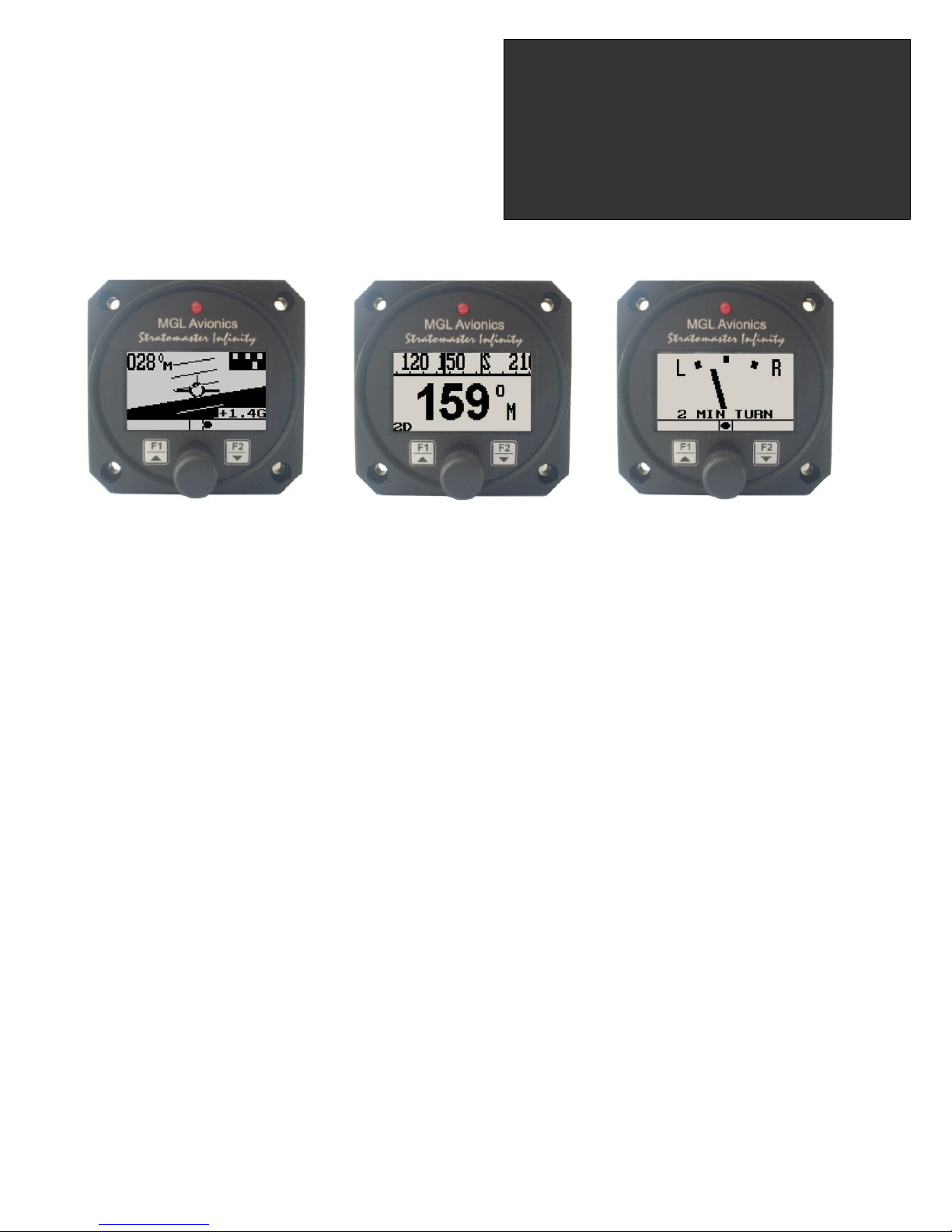
Introduction
The AV-1 is a 2 1/4” instrument that can be used as a display interface for an artificial horizon reference system (AHRS),
advanced digital compass, or both depending on which MGL Avionics sensor packages is connected to the AV-1.
The AV-1 can be setup to display the following:
• Compass with five different displays (requires MGL Avionics SP-2/6 sensor package)
• Horizon with or without slip indicator (requires MGL Avionics SP-3/4/5/7 sensor package)
• Turn and bank indicator (requires MGL Avionics SP-3/4/5/7 sensor package)
• Combined compass and horizon display with bank indicator and optional slip indicator (requires MGL Avionics
SP2/6 & SP-3/4/5/7 sensor package)
You can also share sensor packages between various different sizes of instrument e.g. Velocity AV-2 units (these have a
3 1/8” display). For example you may want a 3 1/8” horizon display but a 2 1/4” compass/turn and bank indicator.
1 Features
• Artificial horizon reference system (AHRS) display unit with slip indication as well as turn and bank
indication
• Advanced magnetic compass with course steering feature
• Can be setup as an individual compass display, artificial horizon or both
• The AV-1 is connected to the sensor packages by a simple 2 wire communication link. This allows for the
optimum placement of the sensor package in the aircraft
• More then one AV-1 can be connected onto an airtalk link. This allows the compass, artificial horizon and
the turn and bank indicator to be displayed on different AV-1/2 units
• G-Force indicator (SP4/5/7 required)
• Standard 2 1/4” aircraft enclosure (can be front or rear mounted)
• Rotary control plus 2 independent buttons for easy menu navigation and user input
• A red LED illuminates when the artificial horizon sensor range has been exceeded
• Large backlit graphic LCD with adjustable contrast
• Wide input supply voltage range of 8 to 30V DC with built in voltage reversal and over voltage protection
for harsh electrical environments
• Light weight design
• Field upgradeable firmware
• 1 year limited warranty
Infinity AV-1
Artificial horizon and advanced
magnetic compass indicator
Operating Manual – English 1.07
Page 50
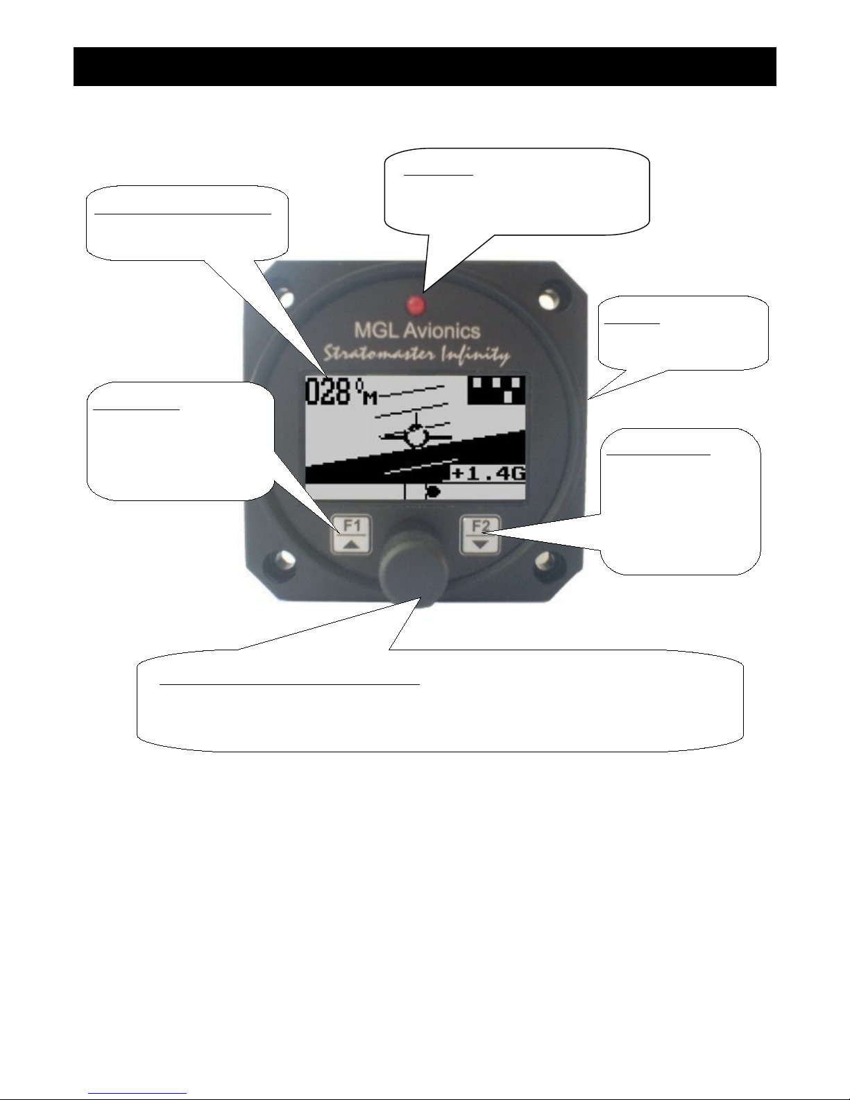
Infinity AV-1 Operating Manual Page 2
2 Layout
3 Main Display
The AV-1 can be set up to show 3 different display screens. Turning the rotary control either clockwise or anti-clockwise
allows you to select the operation of the AV-1 as an artificial horizon with mini compass, mini turn and bank indicator, turn
and bank indicator, and a digital compass.
Note: If you have purchased the artificial horizon and compass sensor packages with two or three AV-1 or AV-1 displays,
it is possible to setup either of the AV-1 units to display either the artificial horizon, turn and bank indicator or the compass.
This allows you to use any combination of horizon, turn and bank or compass displays. You can connect further AV-1 or
AV-2 units should you require this for a dual cockpit layout. Up to six AV units can be configured to give you 2 x horizon, 2
x turn and bank as well as 2 x compass displays.
LED alarm:
The red LED will illuminate if the
artificial horizon has exceeded its
maximum rate of bank, pitch or yaw
Backlit graphic LCD display:
Contrast and backlight can be
adjusted in the menu system
Up/F1 Button:
Up button in menu system
Artificial Horizon: Pitch level
function
Compass: Enable course
steering display
Rotary Control (Up/Down) & Enter Button:
Press the rotary control during normal mode to access the menu system. Rotate anti/clockwise
for up/down menu scrolling. During normal mode turning the rotary control anti/clockwise will
scroll through the main displays (Artificial horizon, compass and turn and bank indicator).
Down/F2 Button:
Down button in menu
system
Artificial Horizon:
Fast level function
Compass: Enable
the reverse course
display
Harness:
Harness connects to power
and airtalk bus.
Page 51
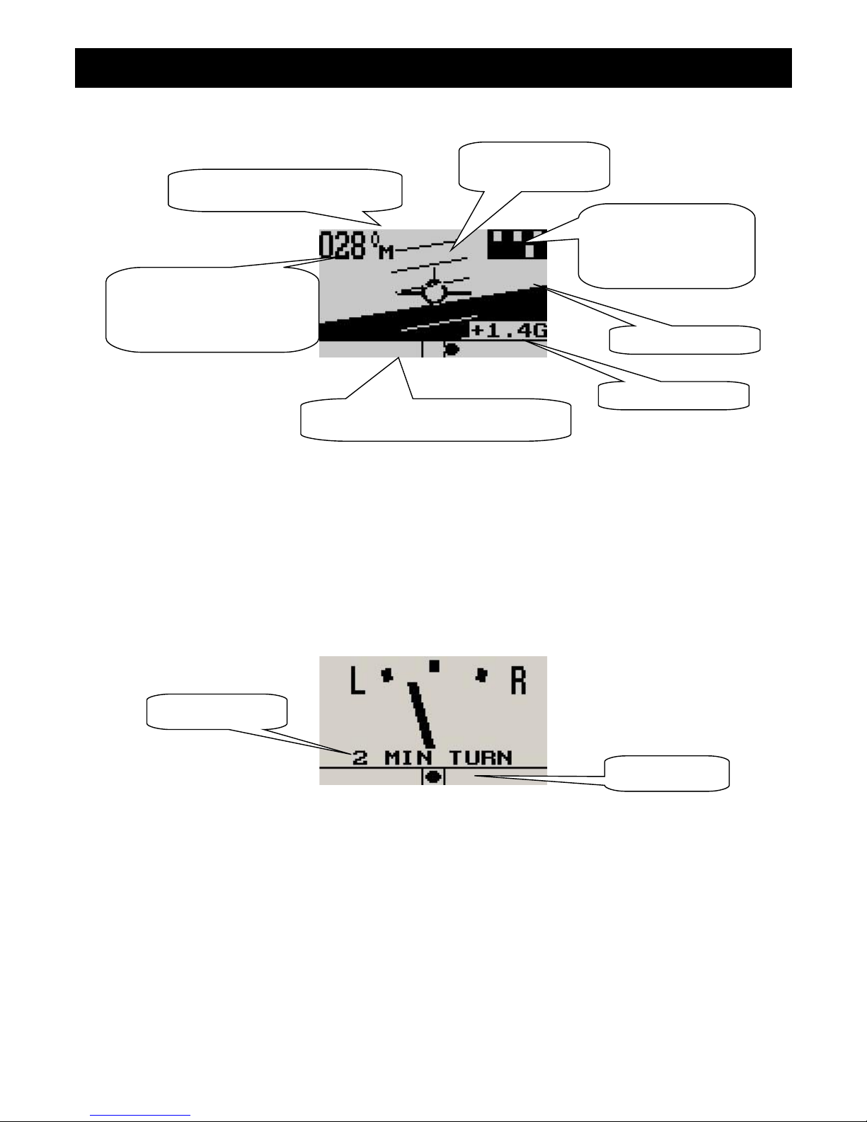
Infinity AV-1 Operating Manual Page 3
3.1 Artificial Horizon with Compass
Pitch level function
Should your aircraft fly “nose up” or “nose down” due to trim, then you can press the F1 key to level the pitch as displayed
on the horizon.
3.2 Turn and Bank Indicator
The slip indicator is always enabled, regardless of the slip on/off setting.
Slip indicator
A “step on the ball” slip indicator can be enabled to appear below the horizon display. The source of information for this
indicator is derived from the accelerometer aligned with the pitch axis of the aircraft, i.e. the acceleration forces acting in
the direction of the wings.
Fast level function
Press the F2 key should the horizon display be toppled (i.e. indicating incorrectly by a large amount) due to excessive
maneuvering or by exceeding the maximum bank, pitch or yaw rates. This will indicate to the instrument that you are
flying straight and level and that gravity tracking may be accelerated to ensure rapid realignment of the horizon.
Estimated horizon
10 degree pitch
bars
Slip indicator can be turned on or off in
the menu system
Magnetic (M) or true heading (T)
indicator
Magnetic or true heading
reading (compass can be
switched on or off in the menu
system)
Slip indicator
Marker description
Mini turn and bank
indicator (can be
switched on or off in the
menu system)
G-Force display
Page 52
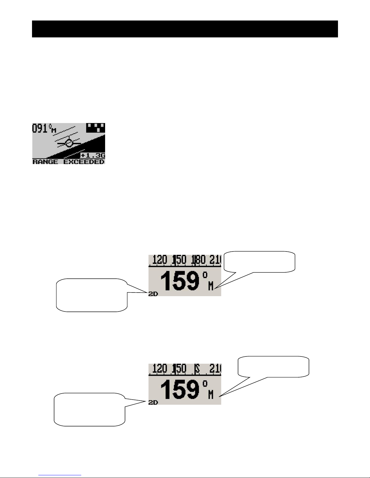
Infinity AV-1 Operating Manual Page 4
Extended range of operation
Bank operates over a full 360 degree range allowing unlimited use of the horizon for aerobatics, provided that the
maximum published bank, pitch and yaw rates are not exceeded. Please see the corresponding MGL sensor
documentation for maximum rate specifications.
Depending on conditions maximum rates may reach 180 degrees per second. No caging of the electronic gyro system is
required during excessive maneuvering or aerobatics, unlike systems based on mechanical gyros. Simply correct the
horizon when you are finished or let the horizon right itself which will happen during straight and level flight. The message
below is displayed for 15 seconds when the range is exceeded.
Message displayed when the maximum bank, pitch or yaw rates have been exceeded
3.3 Digital Compass
The digital compass can be displayed in 5 different ways. The way the compass is displayed can be setup in the menu
system under “COMPASS SETUP”
3.3.1 Numeric compass display
The heading tape shows headings as numbers in degrees.
3.3.2 Mixed compass display
The heading tape shows headings as number in degrees except for the four major cardinal points which are shown as N,
S, E and W.
Magnetic (M) or true
(T) North indicator
Magnetic (M) or true
(T) North indicator
Please see the table
under section 4.4 for
more information
about this icon
Please see the table
under section 4.4 for
more information
about this icon
Page 53
Infinity AV-1 Operating Manual Page 5
3.3.3 Cardinal 1 compass display
The heading tape shows headings as major and minor cardinal points: N, NNE, ENE, E, ESE, SSE, S, SSW, WSW, W,
WNW, and NNW.
3.3.4 Cardinal 2 compass display
The heading tape shows headings as major and intermediate cardinal points: N, NE, E, SE, S, SW, W and NW.
3.3.5 Rose compass display
The display shows a graphic representation of a vertical compass card.
3.3.6 Using the course steering indicator
To activate the course steering indicator, steer the required heading and then press the F1 key. The compass will display:
The F1 key pressed at a heading of 89 degrees. Currently the heading equals the course
to steer as shown below the heading. No course steering indicators are shown.
Magnetic (M) or true
(T) North indicator
Magnetic (M) or true
(T) North indicator
Magnetic (M) or true
(T) North indicator
Please see the table
under section 4.4 for
more information
about this icon
Please see the table
under section 4.4 for
more information
about this icon
Please see the table
under section 4.4 for
more information
about this icon
Page 54
Infinity AV-1 Operating Manual Page 6
The current heading is 85 degrees; course steering indicators show the need to steer
slightly to the right to intercept the course.
The current heading is 42 degrees; course steering indicators show that a large correction
to the right is required to intercept the course.
Each “>” or “<” equals 2 degrees of heading error. To cancel the course steering function, simply press the F1 key again.
3.3.7 The reverse course (from heading) display
Press the F2 key to activate the reverse course display. This display remains active for
about 5 seconds before reverting back to the normal heading display.
Heading stability issues
You may find short term fluctuations of the heading occurring. These tend to be very small and are typically less than one
degree. This could still cause the heading to fluctuate occasionally by a single degree. These fluctuations occur naturally
in the earth’s magnetic field and can also be caused by nearby electrical equipment such as radios, lamps, electronic
instrumentation or computers, even the ignition systems of engines. The AV-1 is specifically designed for fast response
and thus may show residual fluctuations of the magnetic field that are impossible to filter out without causing delays in the
update of the heading information.
3.4 Sensor communication error
Should the AV-1 lose communication with the SP-X instrument for the duration of 5 seconds or more, the AV-1 will display
the following message:
Page 55
Infinity AV-1 Operating Manual Page 7
4 Menu System
Pressing the rotary control button during the normal display mode will cause the AV-1 to enter the menu system. Use the
up/down keys or the rotary control to navigate through the menu system.
4.1 Exit Menu
Pressing the rotary control on this menu item will cause the AV-1 to exit the menu system. All
changes made during navigation of the menu system will be saved in non-volatile memory on exit . If
you remove power before exiting the menu the instrument will not save any changes.
4.2 Display Setup
Move the highlight over the “DONE” menu item and press the rotary control to return to the main
menu.
Select this menu option to adjust the display contrast.
Select this menu option to turn the backlight on or off.
4.3 Artificial Horizon Setup
Page 56
Infinity AV-1 Operating Manual Page 8
Move the highlight over the “DONE” menu item and press the rotary control to return to the main
menu.
Select if you would like to enable the slip indicator to be shown underneath the horizon display. The
slip indicator operates in the same fashion as the well known “step on the ball” indicator in traditional
cockpits.
Note: The slip indicator is always enabled in the turn and bank indicator mode.
This function allows you to set your slip indicator to exactly zero even if your aircraft tends to fly
slightly wing down. The procedure is to place the aircraft in a stable, straight and level attitude
during calm flight conditions and then select this function. To cancel the correction, place your
sensor absolutely horizontal (use a spirit level) and select the function again.
Select if you want the slip to have a high sensitivity or a low sensitivity setting.
See corresponding SP-X documentation on using this feature.
See corresponding SP-X documentation on using this feature.
Select whether you want the turn and bank indicator’s information source to be
the bank angle or actual turning information from the gyros (SP-X dependent).
Select whether you want the turn and bank indicators to show a 1 min/rotation or 2 min/rotation turn.
Select whether you want the mini turn and bank indicator to be shown on the horizon display screen
Select if you would like to see a numeric display of bank and pitch angles superimposed on
the horizon display.
Select between a large or small aircraft icon on the artificial horizon display screen.
Select if you would like to see the G-Force displayed on the horizon screen.
Page 57
Infinity AV-1 Operating Manual Page 9
4.4 Compass Setup
All compass related parameters are set up here.
Move the highlight over the “DONE” menu item and press the rotary control to return to the main
menu
Select whether you want the mini compass to be shown on the horizon display screen.
Select if you are using "GROUND" calibration (older SP-X magnetic units) or the new "INFLIGHT"
calibration as used in the SP-6.
Select the desired compass display mode as described in section 3.4 above
Select whether you would like the instrument to display magnetic or true heading. If you select
true heading, you need to enter the correct magnetic variation for your location. You can find your
local variation on aeronautical or maritime charts. The heading displays will be augmented with
°M or °T depending on the mode you have selected.
Enter the magnetic variation of your location. This is only used if you would like the instrument to
display true heading. True heading is the heading relative to the geographic North Pole. Magnetic
heading is the heading relative to the magnetic North Pole. Variation is expressed in degrees east
or west. Please note that should you move a long distance, you may have to update the variation
setting. This setting may be ignored if you only use the magnetic heading display option.
Start/Stop In-Flight calibration. See In-Flight calibration procedure below. This menu item is only
shown if the "INFLIGHT" calibration is selected for type.
In-Flight calibration Procedure
Please see documentation supplied with the SP-6 for more information.
Fly the aircraft in safe area where you can perform random banked turns. Do not exceed the safety limits of the aircraft
during the calibration flight.
Start the calibration in the Compass setup menu by selecting “START CAL”. The AV-1 will exit the menu system and you
should see the compass heading change to “111” to confirm that calibration has started.
Fly a number of banked 180 or 360 degree turns at different bank angles - i.e. shallow, medium and steep turns. Try to
add many different pitch attitudes in various orientations relative to the field direction. It does not matter in what order you
fly the maneuvers. A typical, good calibration tends to take 5-10 minutes of flight.
Page 58

Infinity AV-1 Operating Manual Page 10
Do not activate any electrical equipment that creates large magnetic fields during the calibration process (for example
starter motors, autopilot servos, landing lights etc). The heading starts reading 111 after you start calibration. After 36
initial samples have been collected this changes to 222. This should take approximately one turn. Continue the flight
while maneuvering until the heading starts reading normally. This happens once the SP-6 has collected 100 distinctly
different magnetic samples. At this point the heading should start showing reasonable numbers. Continue the calibration
flight, settling into straight and level at intervals on different headings and verify the heading readout against an
ACCURATE reference. Continue the flight until you find heading errors that are within 1 to 2 degrees, about the limit one
can reasonably expect.
When satisfied, end the calibration by selecting “STOP CAL” in the compass setup menu. This will save the calibration to
permanent memory in the SP-6. Should you not be able to achieve a good heading readout, please locate the compass to
a better location in the aircraft.
The AV-1 displays the calibration sample count and fit percentage during calibration. The sample count will count up to
150 after which new samples replace the oldest samples stored. The fit percentage is a value from 0% to 100%. The aim
is to get to a value as close as possible to 100%. The fit starts displaying other than 0% after the first 36 samples. Fit
values of 98% and higher are considered good. If you cannot achieve this you do not have a good installation location for
your compass. You may still get reasonably good heading accuracy despite a lower fit. However, to ensure long term
accuracy please consider locating the SP-6 in a better area in your aircraft.
If the readout decreases suddenly by a large amount (for example from 85% to 42%), this is typically caused by a
strong time-variant magnetic field such as can be created by electrical equipment (motors, relays, current flow in cables).
In such a case please either end and restart the calibration or continue the calibration flight until the fit error is acceptable
again (the incorrect magnetic sample(s) will eventually be removed). It is advised to locate the interference source and
either move this or the SP-6 to a better location in the aircraft.
Note: should you move the SP-6 to a new location or fit new equipment close to the SP-6 you will have to perform the
calibration again. There is no practical limit as to how many times you can perform and save a new calibration.
The following menu items are only shown if "GROUND" calibration is selected for type
Select the mode you would like your compass to operate under:
2D: This mode selects a two axis compass system. This has no tilt compensation.
3D A: This mode selects a three axis compass system. Tilt compensation by means of gravity vectoring via
accelerometers.
3D G: This mode selects a three axis compass system. Tilt compensation by means of information supplied by an artificial
horizon.
SP-1 can only be used in 2D mode.
SP-2/6 can be used in modes 2D or 3D A. 3D G is available if an external artificial horizon is connected.
SP-3hc can be used with any of the above modes.
Each mode has advantages and disadvantages over other modes. Briefly, these are outlined in the table below:
Mode Advantages Disadvantages
2D
Most accurate as long as the compass remains level. Not affected
by turns or acceleration provided compass remains level during
turns.
Large heading errors when compass
is tilted.
The magnitude of these errors is
dependent on the heading, type of tilt
(pitch and/or bank) as well as location
on Earth.
3D-A Self-contained tilt compensated compass. Will compensate for most
tilt errors up to 60 degrees of tilt.
Cannot correctly compensate for tilt
during any form of turn due to
centrifugal forces acting on the
Page 59
Infinity AV-1 Operating Manual Page 11
accelerometers.
3D-G
Can provide for accurate heading even during turns as tilt
compensation is based on gyro derived horizon.
Can show very large errors if the
horizon information is invalid which
could have a number of causes such
as exceeding operational limitations of
the horizon system.
Using the deviation calibration feature
When you install your compass sensor package, it may be surrounded by several items or materials that in some way
change the strength and/or direction of the earth magnetic field that your sensors are measuring. If left unattended, this
may contribute to considerable errors in the heading as indicated by your instrument.
Due to the magnetic sensor not being based on a magnetic item (such as a magnetic needle) as in a normal compass,
the effect of deviation is lessened a little. This is because the needle in a magnetic compass will be attracted by iron, even
if the offending iron has no effect on the magnetic field (i.e. does not change the field direction or strength in a
hypothetical case).
Deviation needs to be corrected if you intend using the compass for navigational purposes. The procedure for this is
traditionally called a “compass swing”. Often, two small magnets are placed close to the compass in an effort to correct
some of the larger errors. Smaller, remaining errors are then noted on a “deviation chart” and this is placed next to the
compass for future reference.
With the SP-1, 2,3 and 6, a very simple method can be used to correct for most of the deviation that may be present in
your aircraft or vehicle. However, before you start, ensure that the sensor package is installed as far away as possible
from any of the following:
• Ferro magnetic materials such as iron, many steels and soft magnetic materials such as ferrites. Any magnets
must be located as far away as possible from the sensor package. This includes electromagnets as used in
solenoids, electrical motors and relays.
• Cables containing large electrical currents. DC currents will cause magnetic fields around the cables which will
lead to deviation. AC currents cause fluctuating magnetic fields that may reduce your compass resolution.
• Be aware that some lower grades of stainless steel may be ferro magnetic.
If in any doubt, use a small magnet to test any metals surrounding the sensor package. We recommend mounting the
sensor package using glued on strips of velcro material. This allows for easy alignment of the sensor package horizontal
to the earth’s magnetic field.
Never perform the deviation compensation procedure or a compass swing if your aircraft is placed on a reinforced
concrete apron or tarmac. The steel that may have been used to reinforce may have a very significant effect on the
strength and direction of the magnetic field at your location.
To start the deviation compensation procedure, enter the menu and select “SET DEVIATION”.
Place your aircraft in flight attitude. For example, if you own a tail dragger, raise the tail.
Some tricycle gear aircraft may need to raise the nose gear slightly. The object is to
place the sensor package as close to horizontal attitude relative to the earth’s surface as
possible.
Proceed as instructed and turn the aircraft through a full 360 degrees at least once.
Allow this procedure to take some time, perhaps a minute. You can proceed to turn your
aircraft though two or more turns, however you need to fully complete at least one full
turn.
If you like, you can press the F1 key during this procedure to see the actual numeric data obtained from the
magnetometers. You will see the instrument tracking minimum and maximum values for each sensor and you can see the
current values.
Page 60
Infinity AV-1 Operating Manual Page 12
Once you have completed your turn(s), press the F2 key again to inform the instrument that you have finished. Your
instrument will at this point calculate the best possible fit of the sensor data to a 360 degree arc taking the relative
strengths and offsets of the magnetic field into account. This procedure can result in remarkably good overall
performance of your compass.
Please note: After this procedure has been completed, you may have to verify the compass performance by performing a
normal compass swing. Should any deviation remain, you need to note this on a deviation card and place this card next to
the compass. This may be a legally required procedure in your country for your aircraft class. Please check your relevant
regulations. Deviation compensation and compass swing may need to be repeated from time to time as the magnetic
properties of metals in your aircraft may change over time.
Clears any previous deviation compensation and returns the instrument to factory calibration
The purpose of this function is to cancel out the remaining errors on the main
cardinal headings after a deviation compensation calibration has been done.
Align your aircraft exactly on a North/South heading, pointing North. Use another compass outside of the aircraft to
ensure that you are aligned exactly on the North/South axis. Select the “SET NORTH” function.
Repeat the above calibration for the South, East and West cardinal headings.
This function, if used properly can lessen any remaining deviation that may be present after you have performed the
prescribed compass swing. If you cannot find a successful setting using both methods, examine your installation location
more closely. Perhaps you have an interfering metal part nearby. You may need to choose a different location to mount
the compass sensor.
Note: In difficult circumstances it may not be possible to find a location for the sensor inside the fuselage of your aircraft.
This may be particularly true for aircraft based on tubular steel frames. In this case you need to locate the compass
sensor inside the wing (perhaps in a wing-tip).
5 Operating the Artificial horizon
The horizon is designed to erect itself rapidly whenever possible. This means that during ordinary flight you do not interact
with the unit. The horizon may loose accuracy. This may have several causes:
• You have exceeded the maximum allowable turn rate on one or more axis.
• Continuous maneuvering without giving the unit a chance to correct for errors. In this case gyro drift will eventually
cause a noticeable error in the horizon.
• The IMU is subject to vibration from the engine. Often you will find this will have an effect only at very specific
engine RPM.
• The IMU is subject to rapid temperature changes or is operating outside of the recommended temperature range
(consider re-setting offsets in this case).
• The IMU bump factor is set incorrect for your aircraft. (SP-X dependent). Try a different setting.
In order to correct the horizon display, you need to fly straight and level. The horizon will correct itself in this case given
some time (about 15 seconds to a minute depending on severity of the error and your “slew” setting). You can also press
the F2 key to force an immediate correction. You must fly straight and level for this to work correctly.
Power and trim changes will affect the pitch display of the horizon. You can set the horizon to zero by pressing the F1 key.
To get back to the real horizon, press the F1 key again.
Page 61
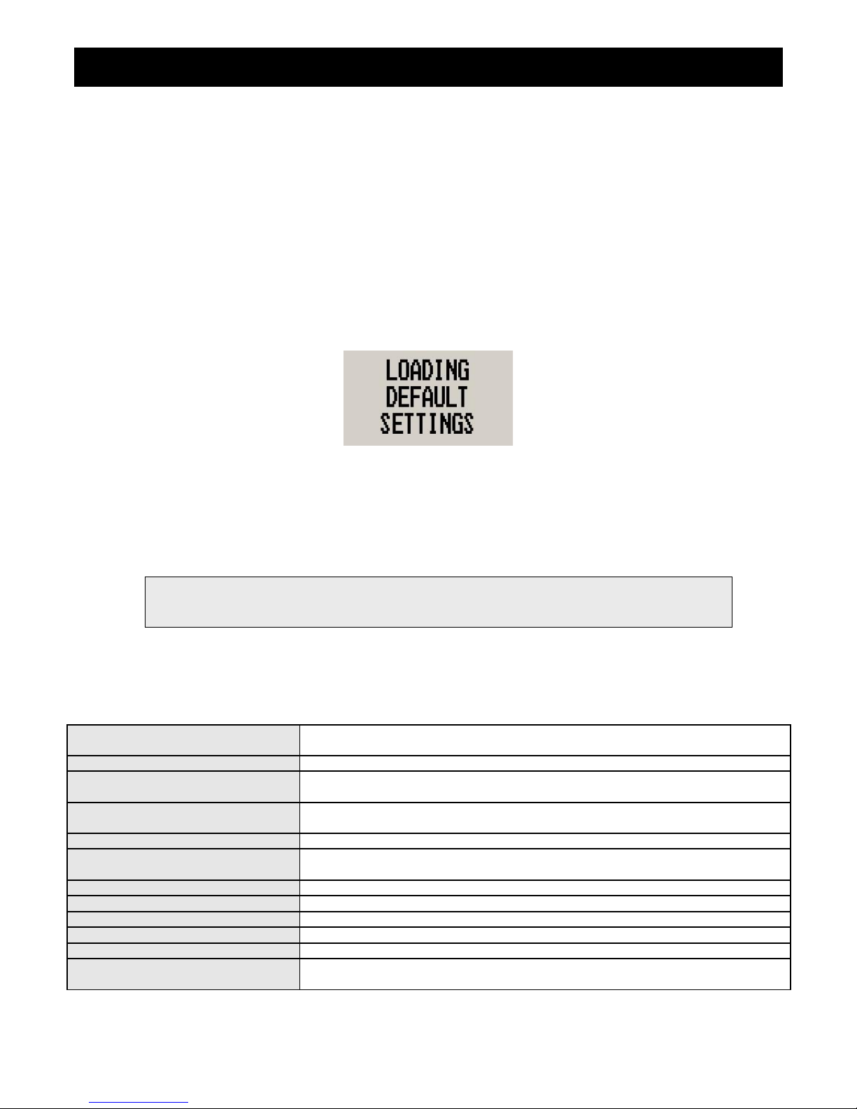
Infinity AV-1 Operating Manual Page 13
6 Using the IMU in flight
The pilot in command of the aircraft has to be aware of the following:
The SP-X sensor packages are not certified by the FAA or any other agency for use during IFR (instrument flight
rules). This implies that any such flight that uses the SP-X IMU as reference for either heading, turn and bank or
horizon is illegal.
7 Loading Factory default settings
Pressing and holding the F1 and F2 keys simultaneously on power up will cause the AV-1 to load the factory default
settings. The following screen will be displayed.
8 Cleaning
The unit should not be cleaned with any abrasive substances. The screen is very sensitive to certain cleaning materials
and should only be cleaned using a clean, damp cloth.
9 Specifications
Operating Temperature Range
-10ºC to 50ºC (14ºF to 122ºF)
Storage Temperature Range -20ºC to 80ºC (-4ºF to 176ºF)
Humidity
<85% non-condensing
Power Supply
8 to 30Vdc SMPS (Switch mode power supply) with built in 33V over voltage and
reverse voltage protection
Current Consumption approx. 38mA @ 13.8V (backlight on), 10mA @13.8V (backlight off)
Display
114x64 graphic LCD display. Contrast and backlight is user configurable,
green/yellow backlight.
Dimensions see Infinity series dimensional drawing
Enclosure 2 1/4” ABS, black in color, front or rear mounting
Weight Approx. 106 grams
Non-volatile memory storage 100000 write cycles
Airtalk protocol 19200 baud, 8 data bits, no parity, 1 stop bit (TTL voltage levels)
MGL Avionics sensor packages
Compass Sensors: SP-2/6
Attitude Sensors: SP-3/4/5/7
Warning: The AV-1 is not waterproof. Serious damage could occur if the unit is exposed to water
and/or spray jets.
Page 62
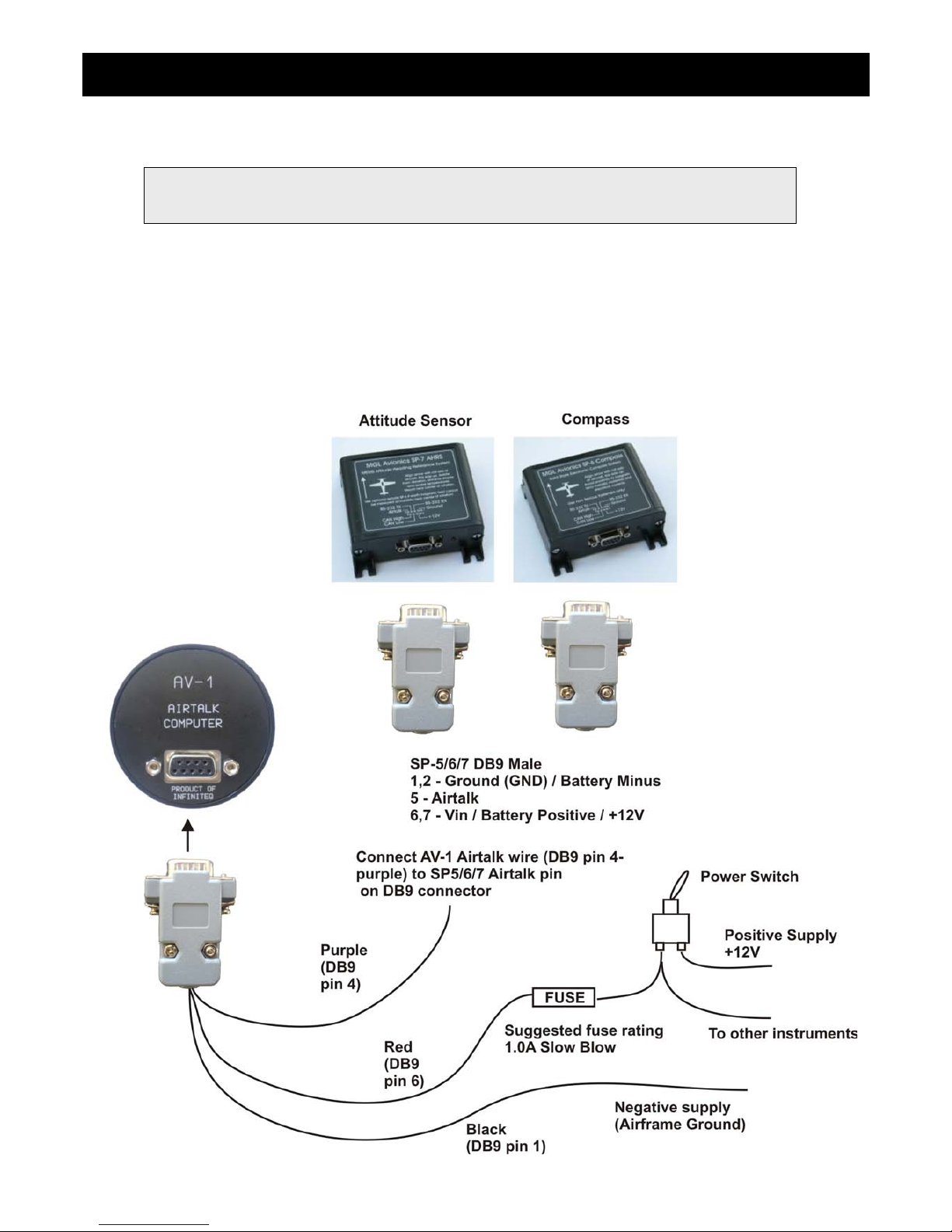
Infinity AV-1 Operating Manual Page 14
10 Installation
10.1 Connection Diagram
The use of an external 1A fuse is recommended. The AV-1 can be used on both 12V and 24V without the use of any preregulators (Please make sure you use a pre-regulator if you intend operating the SP-X sensor package from a 24Vdc
power source). Ensure that the supply voltage will not drop below 8V during operation as this may cause incorrect
readings.
Note: Please see corresponding SP-X sensor package manuals for more information about the
installation and use of the artificial horizon and compass.
Page 63
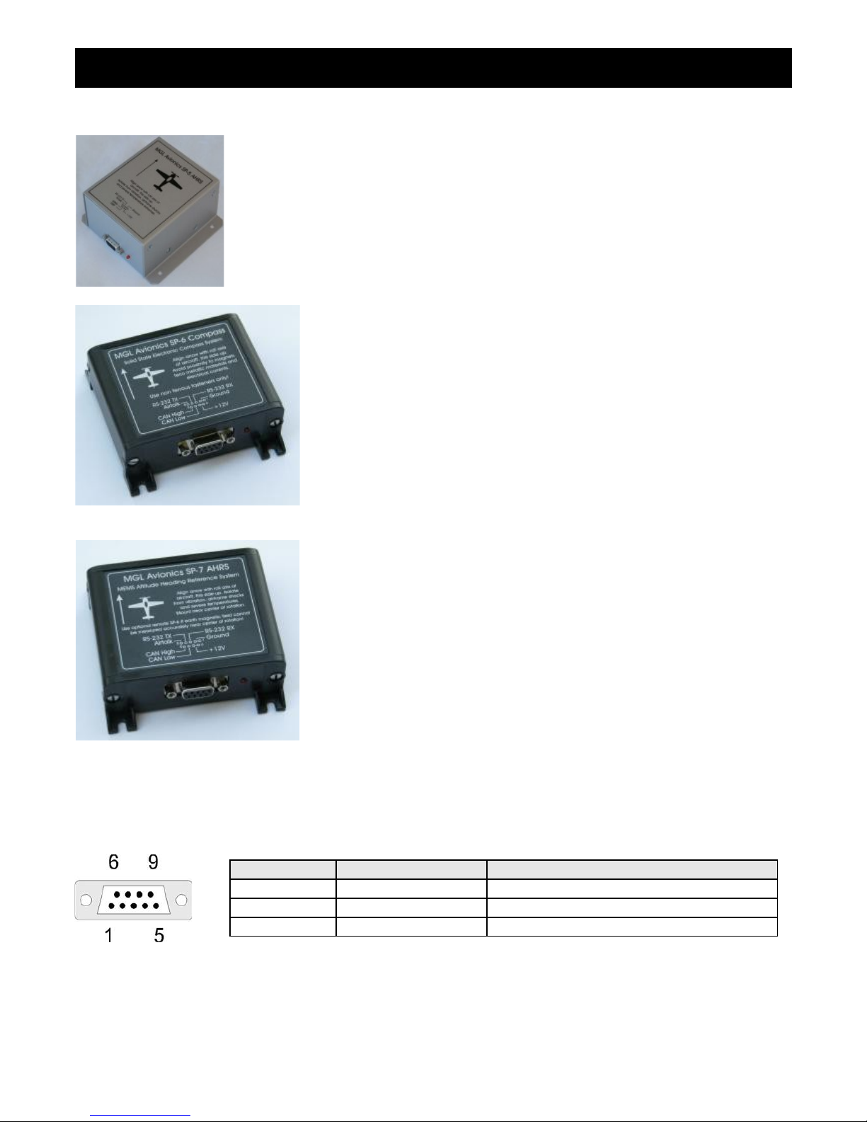
Infinity AV-1 Operating Manual Page 15
SP-5 Attitude Sensor package.
SP-6 Compass
SP-7 Attitude sensor package
10.2 DB9 Cable connections
DB 9 Pin Color Function
1 Black Ground
4 Purple Airtalk communication link
6 Red 8-30Vdc power
Page 64

Infinity AV-1 Operating Manual Page 16
11 Warranty
This product carries a warranty for a period of one year from date of purchase against faulty workmanship or defective
materials, provided there is no evidence that the unit has been mishandled or misused. Warranty is limited to the
replacement of faulty components and includes the cost of labor. Shipping costs are for the account of the purchaser.
12 Disclaimer
Operation of this instrument is the sole responsibility of the purchaser of the unit. The user must make themselves familiar
with the operation of this instrument and the effect of any possible failure or malfunction.
This instrument is not certified by the FAA. Fitting of this instrument to certified aircraft is subject to the rules and
conditions pertaining to such in your country. Please check with your local aviation authorities if in doubt. This instrument
is intended for ultralight, microlight, home built and experimental aircraft. Operation of this instrument is the sole
responsibility of the pilot in command (PIC) of the aircraft. This person must be proficient and carry a valid and relevant
pilot’s license. This person has to make themselves familiar with the operation of this instrument and the effect of any
possible failure or malfunction. Under no circumstances does the manufacturer condone usage of this instrument for IFR
flights.
Other instruments in the Stratomaster Infinity series
ALT-1 Precision encoding altimeter and vertical speed indicator
ALT-2 Precision encoding altimeter and vertical speed indicator with a serial RS232
transponder output
ASI-1 Airspeed indicator (ASI) with automatic flight log
ASX-1 Encoding aviation altimeter with serial output and airspeed indicator (ASI)
AV-1 Artificial horizon and magnetic compass indicator
BAT-1 Battery voltage and current monitor
E-3 Universal engine monitor
FF-1 Fuel Computer (single or dual fuel tanks)
GF-1 +-10G tilt compensated dual range G-force meter
MAP-1 Manifold pressure and RPM Indicator
RV-1 Universal engine RPM and rotor RPM Indicator
RV-2 Universal turbine RPM / RPM factor display
RTC-2 Aviation real time clock (RTC) and outside air temperature (OAT) display
TC-1 4-Channel thermocouple indicator
TP-1 Universal temperature and pressure gauge
Note: Product warranty excludes damages caused by unprotected, unsuitable or incorrectly wired
electrical supplies and/or sensors, and damage caused by inductive loads.
The manufacturer reserves the right to alter any specification without notice.
Page 65
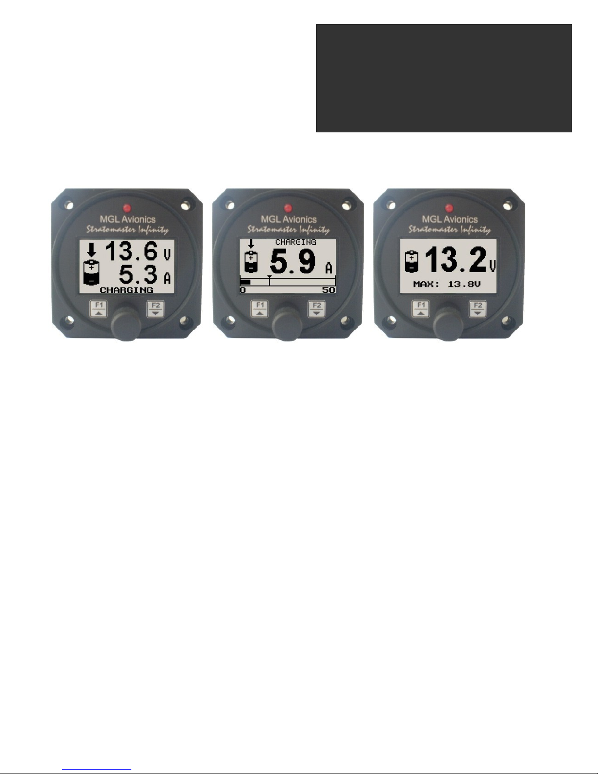
Introduction
The BAT-1 is a 2 1/4” instrument used to monitor your aircraft’s battery power supply. It can be used on lead-acid, NiCad
batteries as well as gel cells. This instrument is very useful in determining your battery’s health, charging status, as well
as the current load consumption of your aircraft. The BAT-1 can be used in both 12V and 24V aircraft and can measure
voltages up to 30V DC.
The BAT-1 uses standard current shunts and is able to measure currents in the range of 5A to 500A.The instrument
contains a programmable low/high voltage alarm to automatically detect bad batteries and alternator failures.
1 Features
• Measure voltage and current simultaneously
• Can measure voltages up to 30V (compatible with both 12V and 24V aircraft supplies)
• Contains a programmable low/high voltage alarm to automatically detect alternator failures and bad
batteries
• Includes a battery charge/discharge indication
• Choice of 3 display modes (volts only, current only, or dual current and voltage display)
• Records maximum volts, charge and discharge currents in permanent memory
• Analog bar graph indicating charge/discharge current
• Multi-language support (English/French)
• Standard 2 1/4” aircraft enclosure (can be front or rear mounted)
• Rotary control plus 2 independent buttons for easy menu navigation and user input
• Alarm output as well as a red LED that illuminates when the alarm has been activated
• Large backlit graphic LCD with adjustable contrast
• Wide input supply voltage range of 8 to 30V DC with built in voltage reversal and over voltage protection
for harsh electrical environments
• Light weight design
• 1 year limited warranty
BAT-1
Battery voltage and current monitor
Operating Manual – English 1.05
Page 66
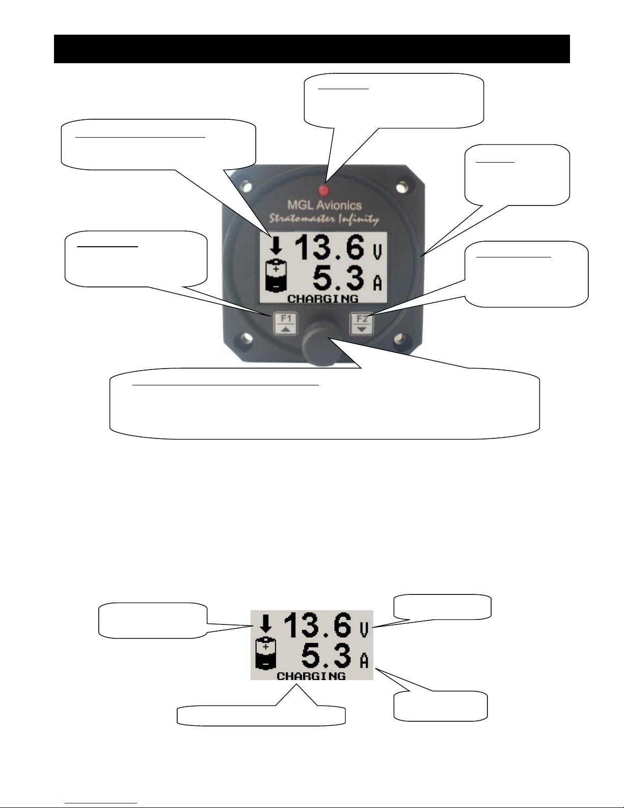
BAT-1 Operating Manual Page 2
2 BAT-1 Layout
3 Main Display
There are 3 main displays that can be setup to be displayed on the BAT-1: dual mode (current and voltage), voltage
display only or current display only. The unit can be setup to toggle manually or automatically between voltage and
current in the single value display modes.
Dual Mode
Backlit Graphic LCD Display:
Contrast and backlight can be adjusted
in the menu system
Harness:
Harness connects
to power and the
current shunt
Up/F1 Button:
Up button in menu system
Maximum values display in
normal mode
Down/F2 Button:
Down button in menu
system
Contrast adjustment in
Rotary Control (Up/Down) & Enter Button:
Press the rotary control during normal mode to access the menu system. Rotate
anti/clockwise for up/down menu scrolling. During normal mode the BAT-1 can be setup to
display either the voltage or current display, then by rotating the rotary control the display
will toggle between the voltage and current displays.
LED Alarm:
The red LED will illuminate if the
voltage alarm set-point has been
exceeded
Current display
Voltage display
Charge/Discharge indication
Charge/Discharge
icon
Page 67
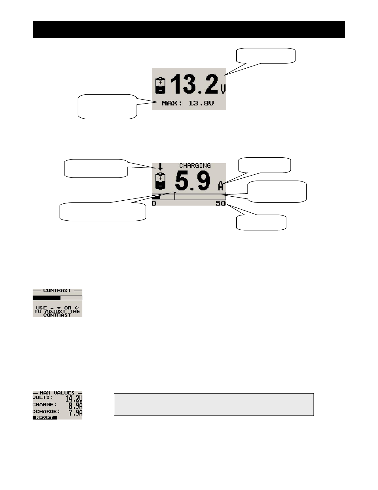
BAT-1 Operating Manual Page 3
Voltage Only
Current Only
3.1 Contrast Display
This display can be accessed by pressing the F2 key during the normal display mode. This is a quick access key to the
same contrast menu in the menu system.
Select this menu option to adjust the display contrast
3.2 Maximum Values Display
This display can be accessed by pressing the F1 key during normal operation. Pressing the F1 key again will reset the
maximum values to the current voltage and current values. Pressing any other key will cause the BAT-1 to return to the
normal display mode. To avoid false recordings, the maximum values function is only activated 10 seconds after the
instrument has powered up.
Note: The permanent maximum values are stored in non-volatile
memory and are recalled on power-up.
Voltage display
Maximum voltage
reached
Current display
Maximum current reached
indicator
Charge/Discharge
icon
Current span
Current analog bar
graph
Page 68
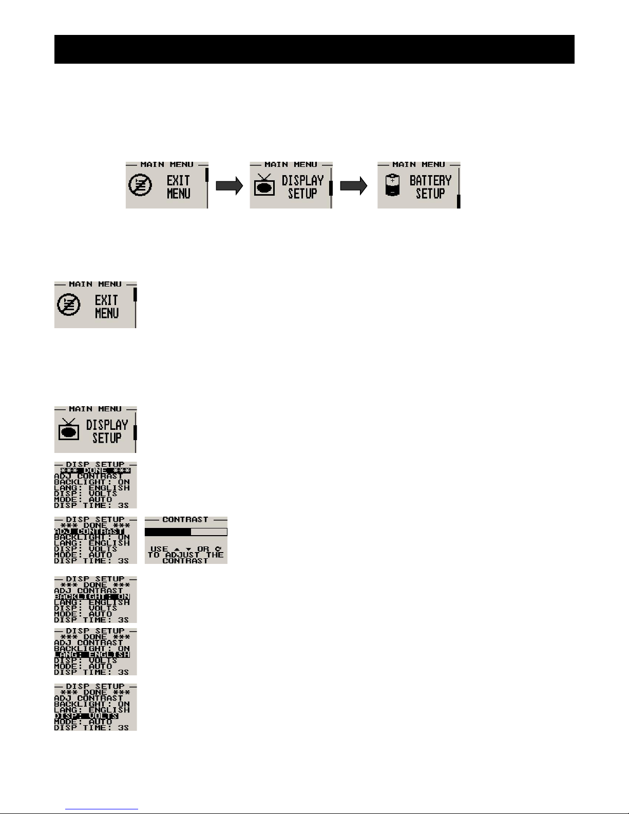
BAT-1 Operating Manual Page 4
4 Menu System
Pressing the rotary control button during the normal display mode will cause the BAT-1 to enter the menu system. Use
the up/down keys or the rotary control to navigate through the menu system.
4.1 Exit Menu
Pressing the rotary control on this menu item will cause the BAT-1 to exit the menu system. All
changes made during navigation of the menu system will be saved in non-volatile memory on exiting
the menu system. If you remove power before exiting the menu the instrument will not save any
changes.
4.2 Display Setup
Move the highlight over the “DONE” menu item and press the rotary button to return to the main
menu
Select this menu option to adjust the display contrast
Select this menu option to turn the backlight on and off
Select your preferred language for the BAT-1. English or French.
Select the display mode of the main display: dual mode, voltage only or current only
Page 69
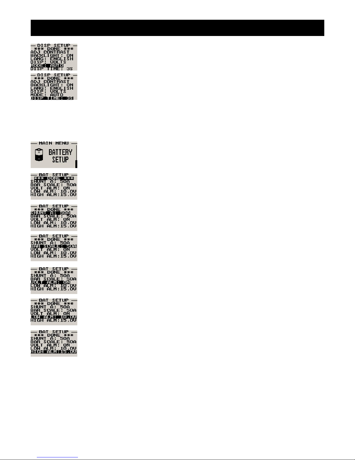
BAT-1 Operating Manual Page 5
Select whether you want the single voltage/current display to alternate automatically or manually
This display is only shown if display mode is setup to show either voltage only or current only
Set the time that the single display modes must be displayed for. This display is only shown if auto is
selected for the display mode
4.3 Battery Setup
All the battery voltage and shunt parameters can be setup here
Move the highlight over the “DONE” menu item and press the rotary button to return to the main
menu
Select the current rating of your current shunt. The BAT-1 can use current shunts in the range of 5A
to 500A.
Select the maximum value that you want the current analog bar graph display to show, i.e. your
current shunt may be a 50A 50mV shunt but the maximum current that you will ever measure is only
7A, then you can scale the bar graph to show a maximum value of 10A. This gives you increased
display resolution
Select whether you want the voltage alarm to be turned on or off. To avoid false activation of the
alarms, the alarm function is only activated 10 seconds after the instrument has powered up.
Enter the low voltage set-point for when the alarm must be activated. Any voltage below this value
will activate the alarm
Enter the high voltage set-point for when the alarm must be activated. Any voltage above this value
will activate the alarm
Page 70
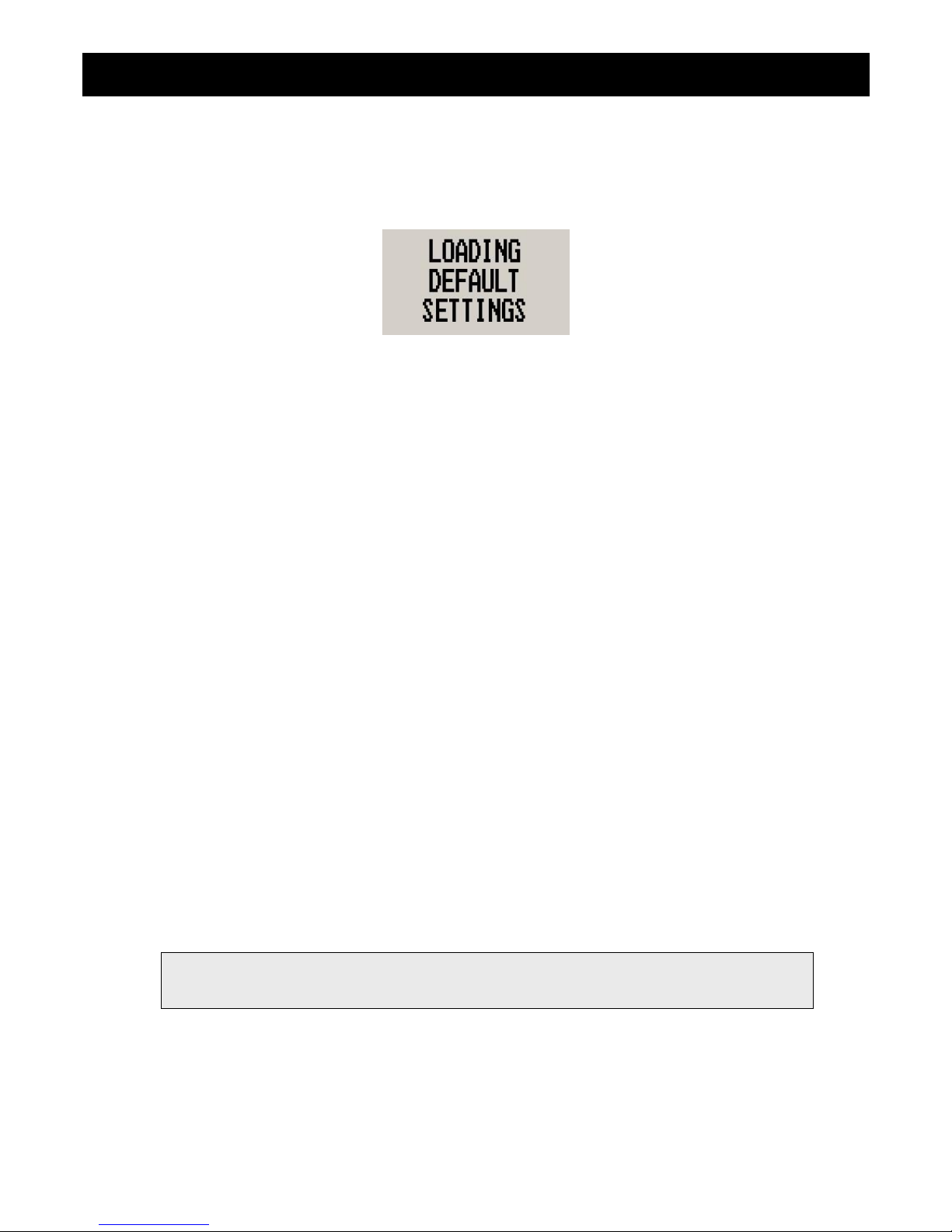
BAT-1 Operating Manual Page 6
5 Loading Factory default settings
Pressing and holding the F1 and F2 keys simultaneously on power up will cause the BAT-1 to load preprogrammed
factory default settings. The following screen will be displayed:
6 Operating the alarms
If the alarm is activated, the corresponding item on the display will flash. At the same time the externally available alarm
switch will close. The switch will remain closed until any button is pressed to acknowledge the alarm or until the
condition(s) that activated the alarm no longer exist. The alarm output can be used to switch an external alarm indicator.
The external alarm switch is an open collector transistor switch to ground with a maximum rating of 0.5A DC. It is possible
to wire the alarm contacts of several Stratomaster instruments in parallel should this be desired. To avoid false activation
of the alarms, the alarm function is only active 10 seconds after the instrument has powered up.
7 Current shunt selection
The BAT-1 can use a current shunt in the range of 5A to 500A, 50mV. Please note that the current shunt rating can affect
resolution and accuracy of the BAT-1. Select a current shunt that is right for your application by using a shunt that is rated
close to the maximum current that you are measuring.
The BAT-1 has a resolution of 0.1A up to 10A and 1A from 10A to 500A. If the current shunt selected is above 100A then
the resolution is fixed at 1A. The BAT-1 has an over range warning if you exceed the current rating of the shunt by +-10%.
8 Cleaning
The unit should not be cleaned with any abrasive substances. The screen is very sensitive to certain cleaning materials
and should only be cleaned using a clean, damp cloth.
Warning: The BAT-1 is not waterproof. Serious damage could occur if the unit is exposed to
water and/or spray jets.
Page 71
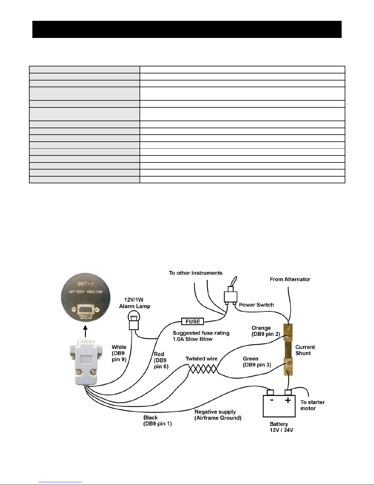
BAT-1 Operating Manual Page 7
9 BAT-1 Specifications
Operating Temperature Range -10ºC to 50ºC (14ºF to 122ºF)
Storage Temperature Range -20ºC to 80ºC (-4ºF to 176ºF)
Humidity <85% non-condensing
Power Supply
8 to 30Vdc SMPS (switch mode power supply) with built in 33V over voltage
and reverse voltage protection
Current Consumption Approx. 30mA @ 13.8V (backlight on) 15mA @13.8V (backlight off)
Display
114x64 graphics LCD display. Contrast and backlight is user configurable,
green/yellow backlight
ADC 12bit over sampled successive approximation
Dimensions see Infinity series dimensional drawing
Enclosure 2 1/4” ABS, black in color, front or rear mounting
Weight Approx. 85 grams
Alarm contact current rating Open collector transistor switch to ground. Maximum rating 0.5A DC
Non-volatile memory storage 100000 write cycles
Current shunt supported 50mV, 5A to 500A
Current resolution 0.1A from 0 to +-10A (Current shunt<=100A), 1A above 10A
Voltage resolution 0.1V
10 Installation
Make sure that the starter motor does not go through the shunt resistor. This will cause excessive current to be drawn
and can result in damage to the shunt. Also check that the cable from the alternator is going through the shunt, so that
charging current can be measured.
10.1 Connection Diagram
Page 72
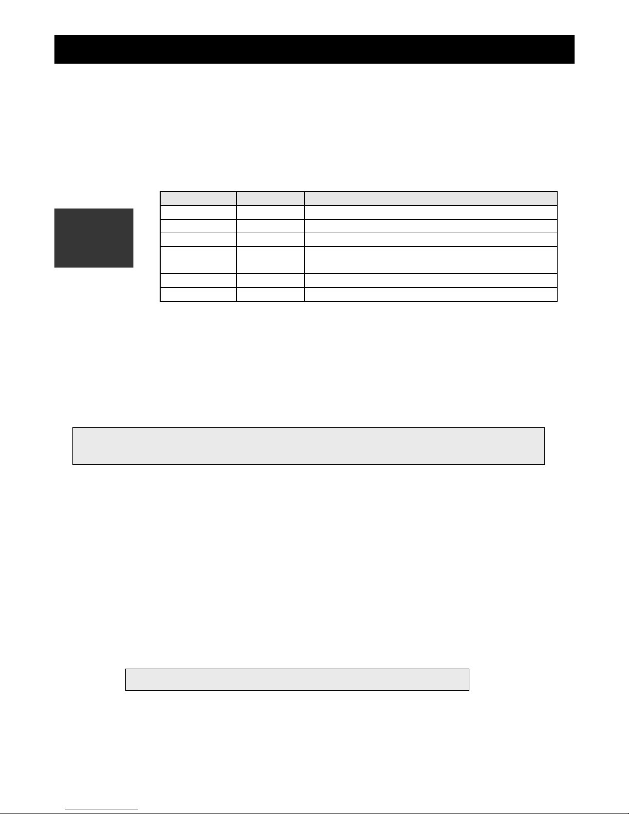
BAT-1 Operating Manual Page 8
The use of an external 1A fuse is recommended. Connect the supply terminals to your aircrafts power supply. The BAT-1
can be used on both 12V and 24V without the use of any pre-regulators. Ensure that the supply voltage will not drop
below 8V during operation as this may result in incorrect voltage and/or current readings.
10.2 BAT-1 DB9 Cable connections
11 Warranty
This product carries a warranty for a period of one year from date of purchase against faulty workmanship or defective
materials, provided there is no evidence that the unit has been mishandled or misused. Warranty is limited to the
replacement of faulty components and includes the cost of labour. Shipping costs are for the account of the purchaser.
12 Disclaimer
Operation of this instrument is the sole responsibility of the purchaser of the unit. The user must make themselves familiar
with the operation of this instrument and the effect of any possible failure or malfunction.
This instrument is not certified by the FAA. Fitting of this instrument to certified aircraft is subject to the rules and
conditions pertaining to such in your country. Please check with your local aviation authorities if in doubt. This instrument
is intended for ultralight, microlight, homebuilt and experimental aircraft. Operation of this instrument is the sole
responsibility of the pilot in command (PIC) of the aircraft. This person must be proficient and carry a valid and relevant
pilot’s license. This person has to make themselves familiar with the operation of this instrument and the effect of any
possible failure or malfunction. Under no circumstances does the manufacturer condone usage of this instrument for IFR
flights.
DB 9 Pin Color Function
1 Black Ground
2 Orange Shunt 3 Green Shunt +
4 NC Airtalk communication (Not connected)
Used for firmware upgrading
6 Red 8-30Vdc power
9 White Alarm Output
Note: Product warranty excludes damages caused by unprotected, unsuitable or incorrectly wired
electrical supplies and/or sensors, and damage caused by inductive loads.
The manufacturer reserves the right to alter any specification without notice.
Page 73
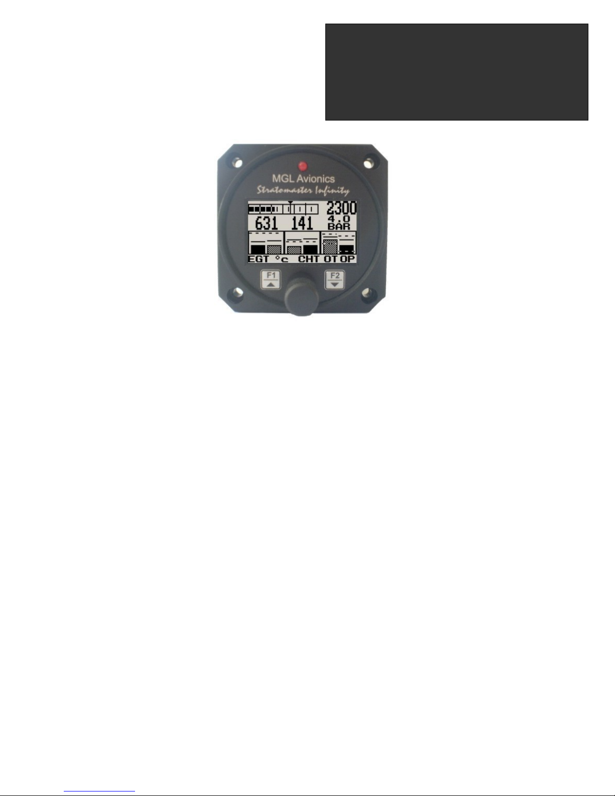
Introduction
The E-3 universal engine monitor combines in one compact 2 1/4” format instrument all that is needed to monitor the
majority of smaller aircraft engines from two-stroke ultra-light engines to medium sized four strokes such as those from
Rotax, Continental and Lycoming. Most automotive engine conversions can also benefit from the use of the E-3 engine
monitor.
The E-3 can measure up to 4 EGT/CHT channels, a universal RPM input, a universal temperature sender input, a
universal pressure sender input and the aircrafts supply voltage.
1 Features
• 66 different engine setup configurations possible
• Universal, programmable rev counter (engine RPM) with digital and analog readout, with a programmable
high alarm limit
• Programmable engine Hobbs meter (password protected) and running timer (flight timer) with automatic
flight log
• Can monitor up to four programmable thermocouple channels for EGT and CHT probes with a user
programmable high alarm limit
• A universal temperature sender input with a user programmable low and high alarm limits
• A universal pressure sender input with a user programmable low and high alarm limits
• Supply voltage measurement up to 30V with a user programmable low and high alarm limits
• Maximum recorded values for all measured values are stored in non-volatile memory
• High accuracy: Built in thermocouple linearization curves and cold junction compensation
• Thermocouple temperature probes can be common K, J or E-type thermocouple probes
• Uses standard automotive temperature and pressure senders
• Special Rotax 912/914 engine monitor mode utilizing the standard built in Rotax NTC CHT probes
• Standard 2 1/4” aircraft enclosure (can be front or rear mounted)
• Rotary control plus 2 independent buttons for easy menu navigation and user input
• External alarm output as well as a red LED illuminates when the alarm has been activated
• Large backlit graphic LCD with adjustable contrast
• Wide input supply voltage range of 8 to 30V DC with built in voltage reversal and over voltage protection
for harsh electrical environments
• Light weight design
• Field upgradeable firmware
• 1 year limited warranty
Infinity E-3
Universal Engine Monitor
Operating Manual – English 1.10
Page 74
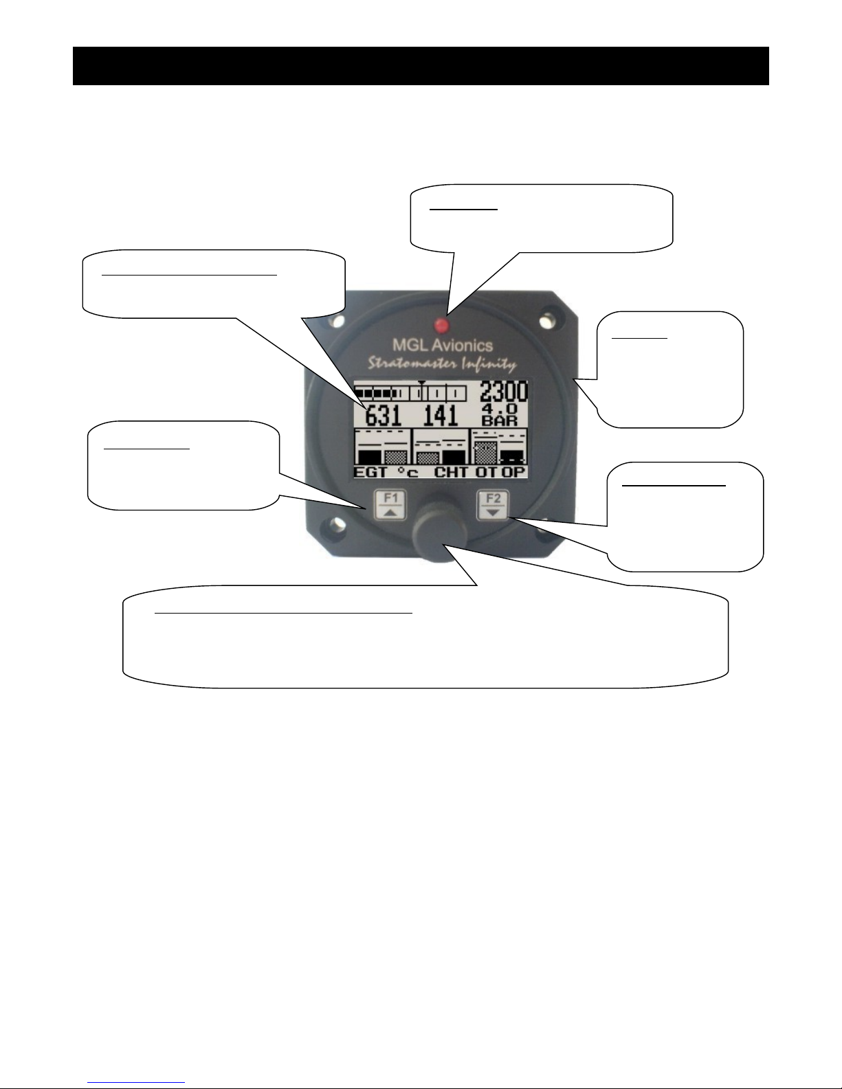
Infinity E-3 Operating Manual Page 2
2 E-3 Layout
Backlit graphic LCD display:
Contrast and backlight can be adjusted
in the menu system
Harness:
Harness connects
to power, EGT/CHT
thermocouples and
temperature and
pressure senders
Up/F1 Button:
Up button in menu system
Start/Stop flight in normal
mode
Down/F2 Button:
Down button in menu
system
Adjust contrast
setting in normal
mode
Rotary Control (Up/Down) & Enter Button:
Press the rotary control during normal mode to access the menu system. Rotate anti/clockwise
for up/down menu scrolling. During normal mode rotating the rotary control clockwise will
display the maximum recorded values, rotating the rotary control anti-clockwise will display the
information screen.
LED alarm:
The red LED will illuminate if any of the
alarm thresholds have been reached
Page 75
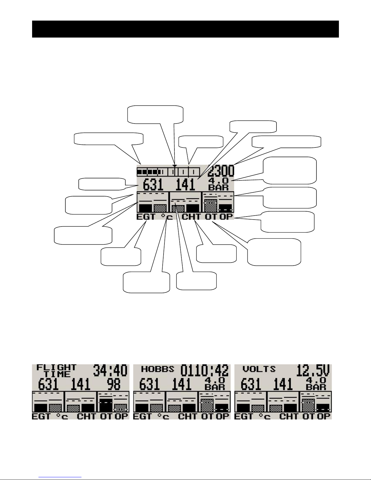
Infinity E-3 Operating Manual Page 3
3 Main Display
The E-3 display can be customized to suite your engine measurement requirements. The E-3 will always try and
maximize the display area in accordance to the measurement variables selected. The E-3 can be configured to how many
EGT and CHT channels you want to display, and whether you want to display a temperature and/or pressure NTC input.
All senders can be disabled or enabled.
3.1 Flight Time / Hobbs Time / Voltage display
The flight time, Hobbs time and voltage displays will alternate at a predetermined interval when the E-3 measures zero
RPM.
Analog RPM display
Maximum RPM
reached marker
RPM Alarm Digital RPM readout
EGT Value
CHT Value
EGT alarm
limit
CHT alarm
limit
Temperature
display unit
Maximum value
reached indicator
EGT group
indicator
CHT group
indicator
User selectable
temperature
label
User selectable
pressure label
Alternating
temperature/
pressure value
High/low alarm
limits
Page 76
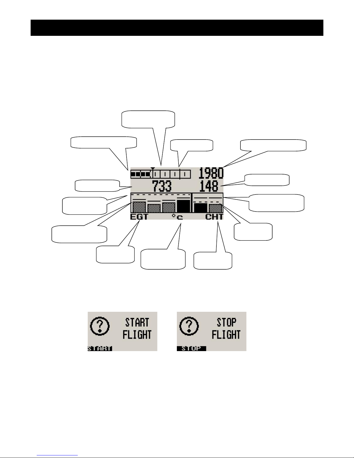
Infinity E-3 Operating Manual Page 4
3.2 Special Rotax 912/914 display mode
In this mode the temperature and pressure NTC inputs becomes CHT channel one and CHT channel 2 respectively. All
CHT setups must still be done under the “CHT SETUP” menu. The sender for the temperature and pressure setup must
be set for “OFF”. A probe setting “NTC” must be selected for the probe setting in the “CHT SETUP” menu. The number of
EGT probes can be selected from 0 to 4.
The reason for using the NTC inputs is that the sensors Rotax use are standard NTC temperature probes and not of a
thermocouple type.
3.3 Start/Stop Flight Display
Press the F1 key during the normal display mode to manually start/stop a flight. This key is only active if the E-3 is setup
to select the manual flight option under the “FLIGHT LOG” setup menu.
Analog RPM display
Maximum RPM
reached marker
RPM Alarm Digital RPM readout
EGT Value
CHT Value
EGT alarm
limit
CHT alarm
limit
Temperature
display unit
Maximum value
reached indicator
EGT group
indicator
CHT group
indicator
Maximum value
reached indicator
Page 77
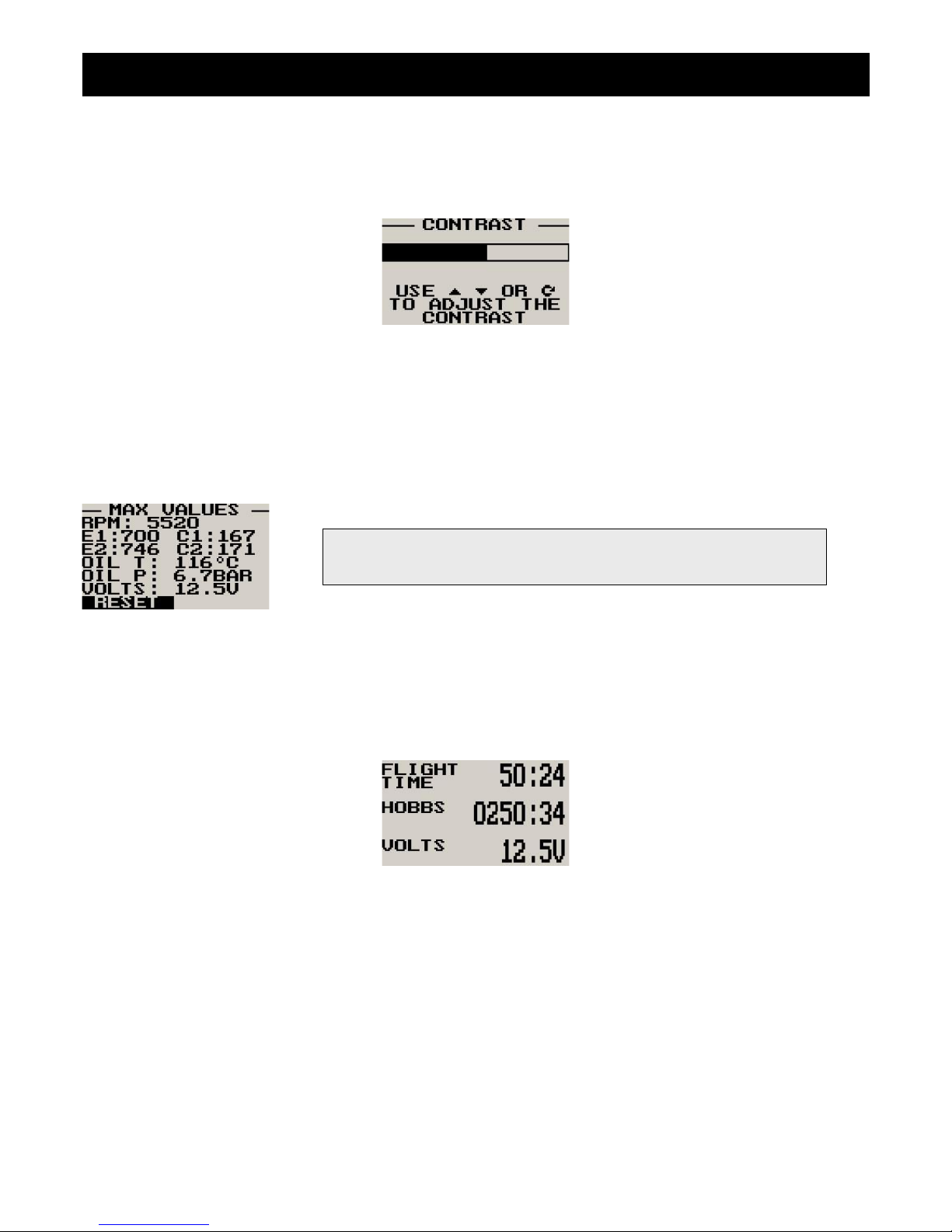
Infinity E-3 Operating Manual Page 5
3.4 Contrast Display
This display can be accessed by pressing the F2 key during the normal display mode. This is a quick access key to the
same contrast menu as in the menu system.
3.5 Maximum Values Display
This display can be accessed by rotating the rotary control clockwise during the normal display mode. Pressing the F1
key will reset the maximum values to the current values. Pressing any other key will cause the E-3 to resume to the
normal display mode. To avoid false recordings, the maximum values function is only activated 10 seconds after the
instrument has powered up.
3.6 Information Display
This display can be accessed by rotating the rotary control anti-clockwise during the normal display mode. This display
shows the current flight time, the hobbs timer and the supply voltage value. Pressing any key will cause the E-3 to resume
to the normal display mode.
3.7 Maintenance Timer
The purpose of this function is to assist you in determining remaining hours until maintenance will be required. It is not
intended as a replacement for the aircraft's maintenance log. It is therefore important that the aircraft's maintenance log
be maintained in the normal manner. You should further use your own discretion in performing maintenance earlier than
indicated should any aircraft performance problems arise.
A maximum of 999 hours can be entered as a maintenance interval. The E-3 will deduct actual engine running time from
the maintenance interval hours as set and will display the reminder message on startup when zero hours are remaining.
The reminder message will automatically disappear after 5 seconds or if the pilot presses any key. Engine running time
for the purpose of the maintenance timer is defined as the run time where the engine RPM is greater than the preset RPM
for the Hobbs meter.
Note: The permanent maximum values are stored in non-volatile
memory and are recalled on power-up.
Page 78
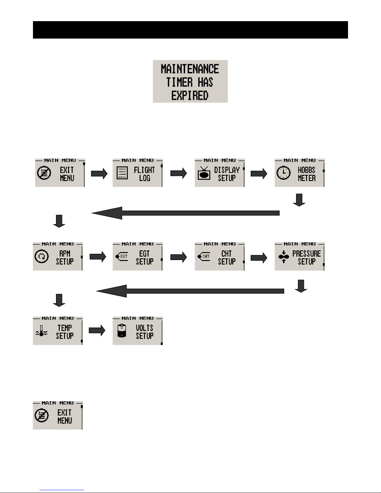
Infinity E-3 Operating Manual Page 6
4 Menu System
Pressing the rotary control button during the normal display mode will cause the E-3 to enter the menu system. Use the
up/down keys or the rotary control to navigate through the menu system.
4.1 Exit Menu
Pressing the rotary control on this menu item will cause the E-3 to exit the menu system. All
changes made during navigation of the menu system will be saved in non-volatile memory on exiting
the menu system. If you remove power before exiting the menu the instrument will not save any
changes.
Page 79
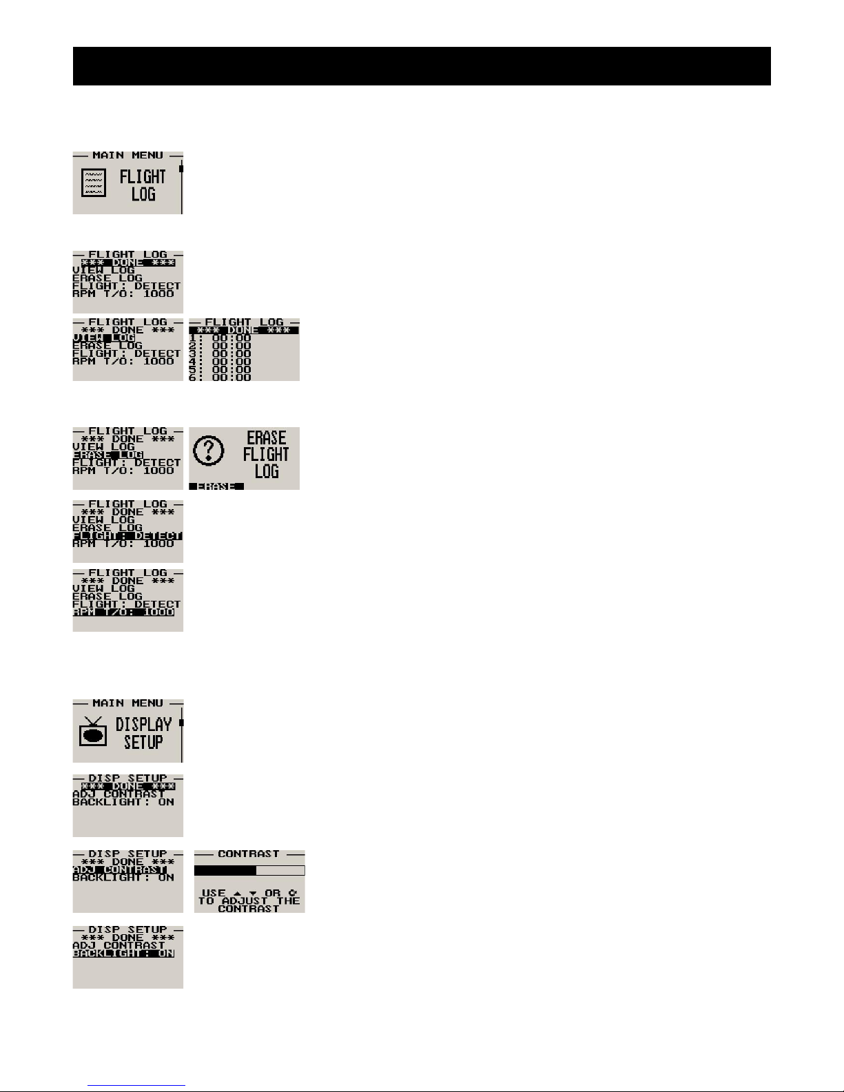
Infinity E-3 Operating Manual Page 7
4.2 Flight Log
Select whether the instrument should detect the start and end of flights automatically or if you would
like to do this manually. We recommend you select automatic flight detect. With automatic flight
detection, flights will start logging when the engine RPM is above the take-off limit. A flight is
considered ended when the engine RPM is less than the RPM take-off limit for more then 30
seconds.
Move the highlight over the “DONE” option and press the rotary button to return to the main menu.
Select this function to view the flight log. The flight log contains the duration of
each of the last 24 logged flights. Duration is displayed in hours and minutes.
Eight flights are displayed at a time. Use the up/down or the rotary control to
navigate through the log. Empty log entries are shown as “-----“.
Note: You cannot select this function while a flight is in progress.
Pressing the F1 key will erase all the flight log entries.
Select whether you want the E-3 to automatically detect a flight or whether the pilot must press the
F1 key to start/stop a flight. We recommend you select automatic flight detection.
This menu option is only shown if the “DETECT” flight mode is selected. Enter the engine RPM takeoff threshold that you want a flight log entry to start.
4.3 Display Setup
Move the highlight over the “DONE” menu item and press the rotary button to return to the main
menu.
Select this menu option to adjust the display contrast.
Select this menu option to turn the backlight on or off.
Page 80
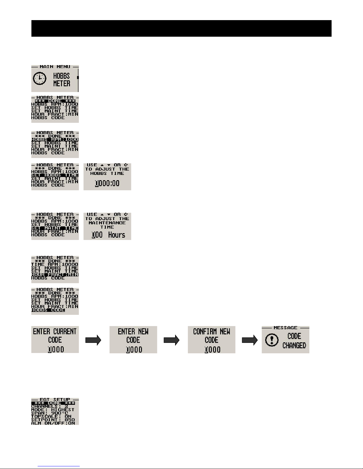
Infinity E-3 Operating Manual Page 8
4.4 Hobbs Meter
Move the highlight over the “DONE” menu option and press the rotary button to return to the main
menu.
Enter the RPM limit in which the Hobbs meter/maintenance timer must start counting.
This function allows you to set the engine Hobbs meter to any value. Typically,
you would use this function to set the Hobbs meter to the current known engine
time. Use the up/down or the rotary control to change the value. Press the
rotary control to accept and exit the menu option. If the Hobbs code is set to
another value beside zero, then the pilot will be prompted to enter the Hobbs
access code before allowing him to change the Hobbs time. This feature is
useful for charted and flying school planes.
This function allows you to set an engine maintenance timer. This timer is set
in engine hours and it will count down to zero when the engine RPM is greater
then the Hobbs RPM limit. A good use for this function is to set the hours until
your next spark plug change or engine inspection. Use the up/down or the
rotary control to change the value. Press the rotary control to accept and exit
the menu option.
Select if you would like the hour to be displayed in decimal fractions (0-99) or minutes (0-59).
This setting influences the current flight time display and the flight log.
This menu option allows you to change the Hobbs access code. You will first be prompted to enter
the current code followed by entering in a new code followed by re-entering the new code. If the new
code and the re-entered code is the same, then the Hobbs access code will be changed. Default
code is 0000.
4.5 EGT (Exhaust Gas Temperature) Setup
Move the highlight over the “DONE” menu option and press the rotary button to return to the main
menu.
Page 81
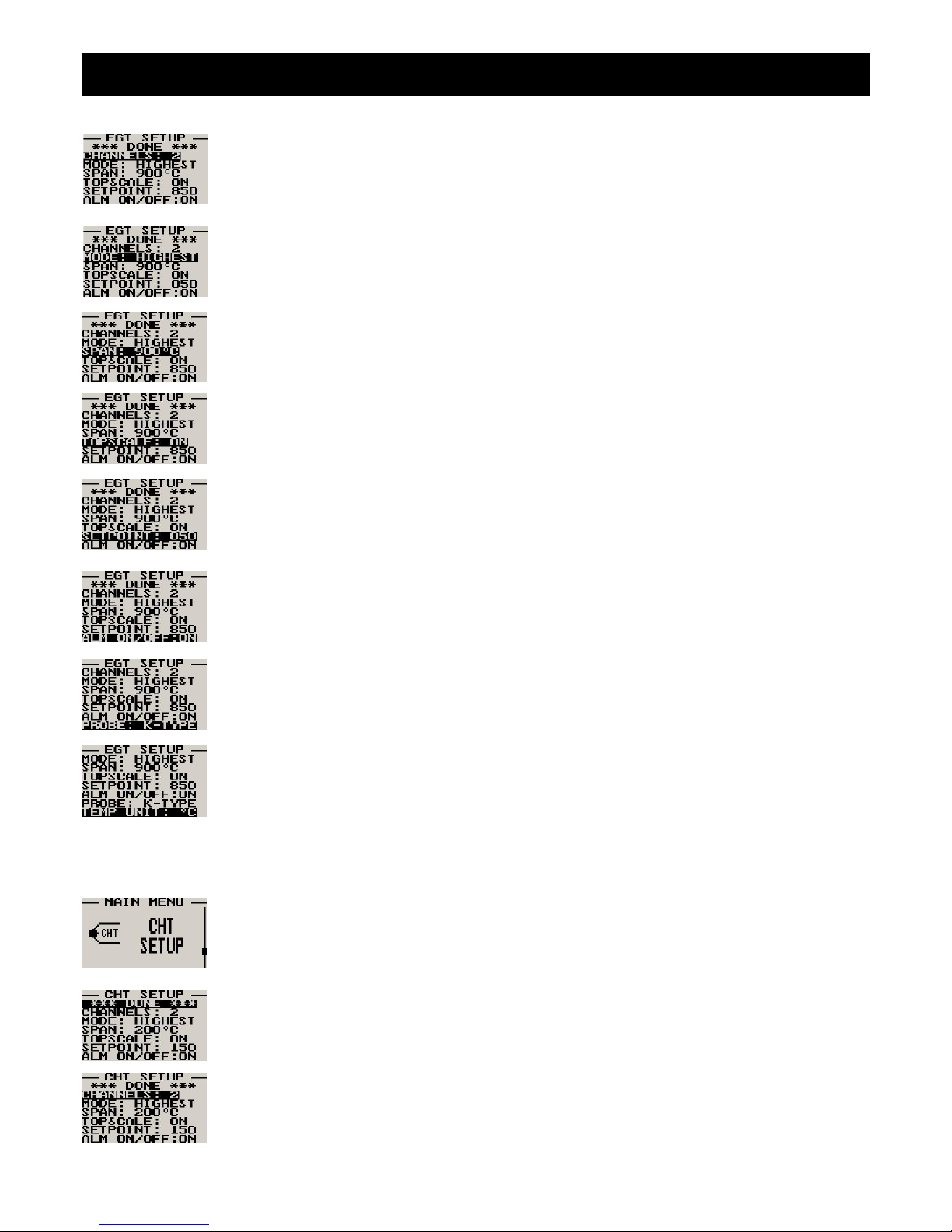
Infinity E-3 Operating Manual Page 9
Select the number of EGT channels you want to use. Choices are from 1 to 4. The temperature
display will configure itself to make best possible use of the available display size. Please note that
the minimum number of EGT and CHT channels that can be displayed is 1 and the maximum
number of EGT and CHT channels that can be displayed is 4.
A selection between “HIGHEST” or “SCANNING” can be selected. If “HIGHEST “is selected then
the current highest thermocouple temperature is displayed. If “SCANNING” is selected then the E-3
will cycle through each thermocouple channel highlighting it as well as showing its temperature.
This function sets the top end of your temperature bar graph. It has no effect on the actual
temperature range that can be displayed in the digital temperature readout. Select the range to be
just higher than the highest temperature you expect to measure using this channel.
Select this function to “ON” if you want the bar graph display to show the upper half of the
temperature range only. This results in a higher resolution of the temperature range that you may be
interested in. For engine temperature measurements we recommend that you set this to “ON”.
Adjust the temperature that you would like to use as an alarm limit. Any temperature above this limit
will activate the alarm. Active alarms will flash the affected channel and also activate the alarm
contact that you can use to switch a lamp on.
Select whether you want to turn the alarm on or off. To avoid false activation of the alarms, the
alarm function is only activated 10 seconds after the instrument has powered up.
Select if you are using a K-type, J-type or E-type thermocouple probe for this channel. All probes
supplied by MGL Avionics are K-Type. J-types are sometimes used with American made CHT
probes. All EGT probes are K-type. E-type probes are seldom used.
Select whether you want all the temperature values to be displayed in degrees Fahrenheit (ºF) or in
degrees Celsius (ºC).
4.6 CHT (Cylinder Head Temperature) Setup
Move the highlight over the “DONE” menu option and press the rotary button to return to the main
menu.
Select the number of CHT channels you want to use. Choices are from 1 to 4. The temperature
display will configure itself to make best possible use of the available display size. Please note that
the minimum number of EGT and CHT channels that can be displayed is 1 and the maximum
number of EGT and CHT channels that can be displayed is 4.
Page 82
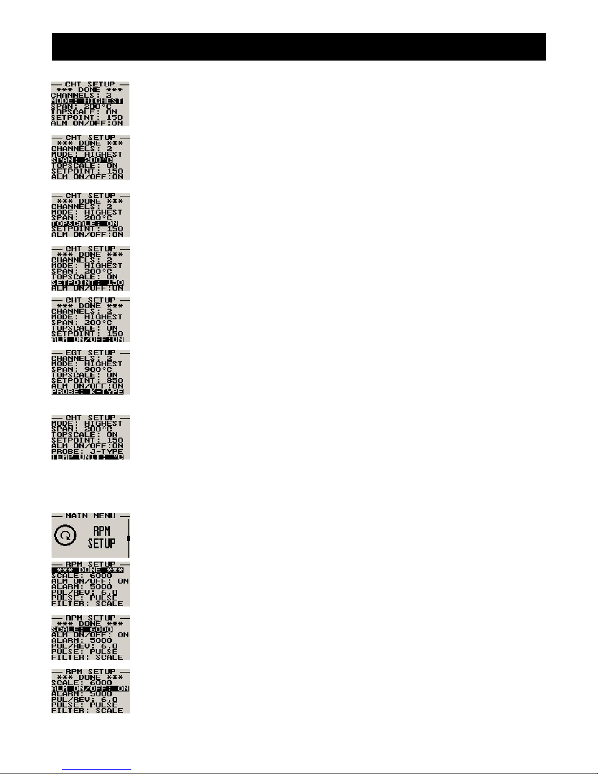
Infinity E-3 Operating Manual Page 10
A selection between “HIGHEST” or “SCANNING” can be selected. If “HIGHEST “is selected then the
current highest thermocouple temperature is displayed. If “SCANNING” is selected then the E-3 will
cycle through each thermocouple channel highlighting it as well as showing its temperature.
This function sets the top end of your temperature bar graph. It has no effect on the actual
temperature range that can be displayed in the digital temperature readout. Select the range to be
just higher than the highest temperature you expect to measure using this channel.
Select this function to “ON” if you want the bar graph display to show the upper half of the
temperature range only. This results in a higher resolution of the temperature range that you may be
interested in. For engine temperature measurements we recommend that you set this to “ON”.
Adjust the temperature that you would like to use as an alarm limit. Any temperature above this limit
will activate the alarm. Active alarms will flash the affected channel and also activate the alarm
contact that you can use to switch a lamp on.
Select whether you want to turn the alarm on or off. To avoid false activation of the alarms, the
alarm function is only activated 10 seconds after the instrument has powered up.
Select if you are using a K-type, J-type or E-type thermocouple probe for this channel. All probes
supplied by MGL Avionics are K-Type. J-types are sometimes used with American made CHT
probes. All EGT probes are K-type. E-type probes are seldom used. If the probe type is set for
“NTC” and the temperature and pressure senders are disabled and 1 or 2 CHT channels are
selected then the unit will enter a special Rotax 912/914 display mode.
Select whether you want all the temperature values to be displayed in degrees Fahrenheit (ºF) or in
degrees Celsius (ºC).
4.7 RPM Setup
All the RPM related settings can be setup here.
Move the highlight over the “DONE” menu option and press the rotary button to return to the main
menu.
Select the maximum value that you want the RPM analog bar graph display to show. This can give
you increased display resolution.
Select whether you want the RPM alarm to be turned on or off.
Page 83
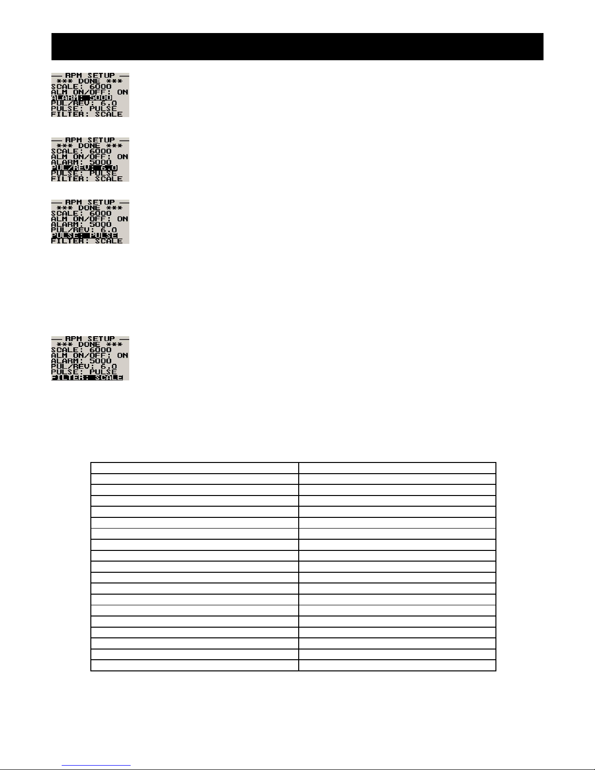
Infinity E-3 Operating Manual Page 11
Enter the RPM alarm activation threshold. Any RPM value above this value will activate the alarm.
Enter the number of pulses per RPM. For engines with an uneven number of cylinders like three
cylinder four stroke engines you can enter values containing fractions (usually 1.5 in this example).
Most four stroke engines will generate one pulse for every two revolutions per cylinder. A four
cylinder automotive four stroke engine will thus generate 2 pulses per revolution. A typical Rotax
DCDI two stroke engine will generate 6 pulses per revolution. The well known Rotax 912/914 engine
generates one pulse per revolution.
PULSE: The E-3 counts pulses from the engine for ½ second period (fast frequency input).
TIME: The E-3 uses the time between pulses to calculate revs (slow frequency input).
Typical setups:
Rotax 503,582 DCDI – Pulse (Fast frequency) (6 pulses per revolution)
Rotax 503 single ignition, Rotax 912/914 – Time (Slow frequency) (one pulse per revolution)
Gyro Rotor RPM with gear tooth sensor - Pulse (Fast frequency) (about 100 pulses per revolution)
Gyro Rotor RPM with single hall-effect sensor – Time (Slow frequency) (one pulse per revolution)
Helicopter Rotor RPM with single hall-effect sensor – Time (Slow frequency) (one pulse per revolution)
The E-3 unit contains a digital filter. This filter is used to achieve a higher resolution of the digital rev
counter than is available in ordinary operation. In digital rev counters, resolution is largely dependant
on the amount of time given to measure RPM. The more time that is available, the higher the
resolution will be. However, on the downside of this, the more sluggish the display will react to
changes in engine settings. Resolution with the E-3 is dependant on the number of pulses per rev
and the type of measurement method you have selected (pulse fast/slow). The update rate for the measurement is a
fixed, fast 0.5 seconds. The digital filter is activated whenever input revs are fairly constant and this results in a very high
resolution of the digital RPM display in a short time span. The filter needs to be setup for the expected base resolution.
This can be between 10 and 30 RPM for most setups. The filter has the following settings:
Scale -The setting is made dependant on your scale selection from 500 to 20000 RPM. The filter factor is fixed as follows:
Scale 500 – 10 RPM Scale 10000 – 200 RPM
Scale 1000 – 20 RPM Scale 10500 – 210 RPM
Scale 1500 – 30 RPM Scale 11000 – 220 RPM
Scale 2000 – 40 RPM Scale 11500 – 230 RPM
Scale 2500 – 50 RPM Scale 12000 – 240 RPM
Scale 3000 – 60 RPM Scale 12500 – 250 RPM
Scale 3500 – 70 RPM Scale 13000 – 260 RPM
Scale 4000 – 80 RPM Scale 13500 – 270 RPM
Scale 4500 – 90 RPM Scale 14000 – 280 RPM
Scale 5000 – 100 RPM Scale 14500 – 290 RPM
Scale 5500 – 110 RPM Scale 15000 – 300 RPM
Scale 6000 – 120 RPM Scale 15500 – 310 RPM
Scale 6500 – 130 RPM Scale 16000 – 320 RPM
Scale 7000 – 140 RPM Scale 16500 – 330 RPM
Scale 7500 – 150 RPM Scale 17000 – 340 RPM
Scale 8000 – 160 RPM Scale 17500 – 350 RPM
Scale 8500 – 170 RPM Scale 18000 – 360 RPM
Scale 9000 – 180 RPM Scale 18500 – 370 RPM
Scale 9500 – 190 RPM Scale 19000 – 380 RPM
Page 84
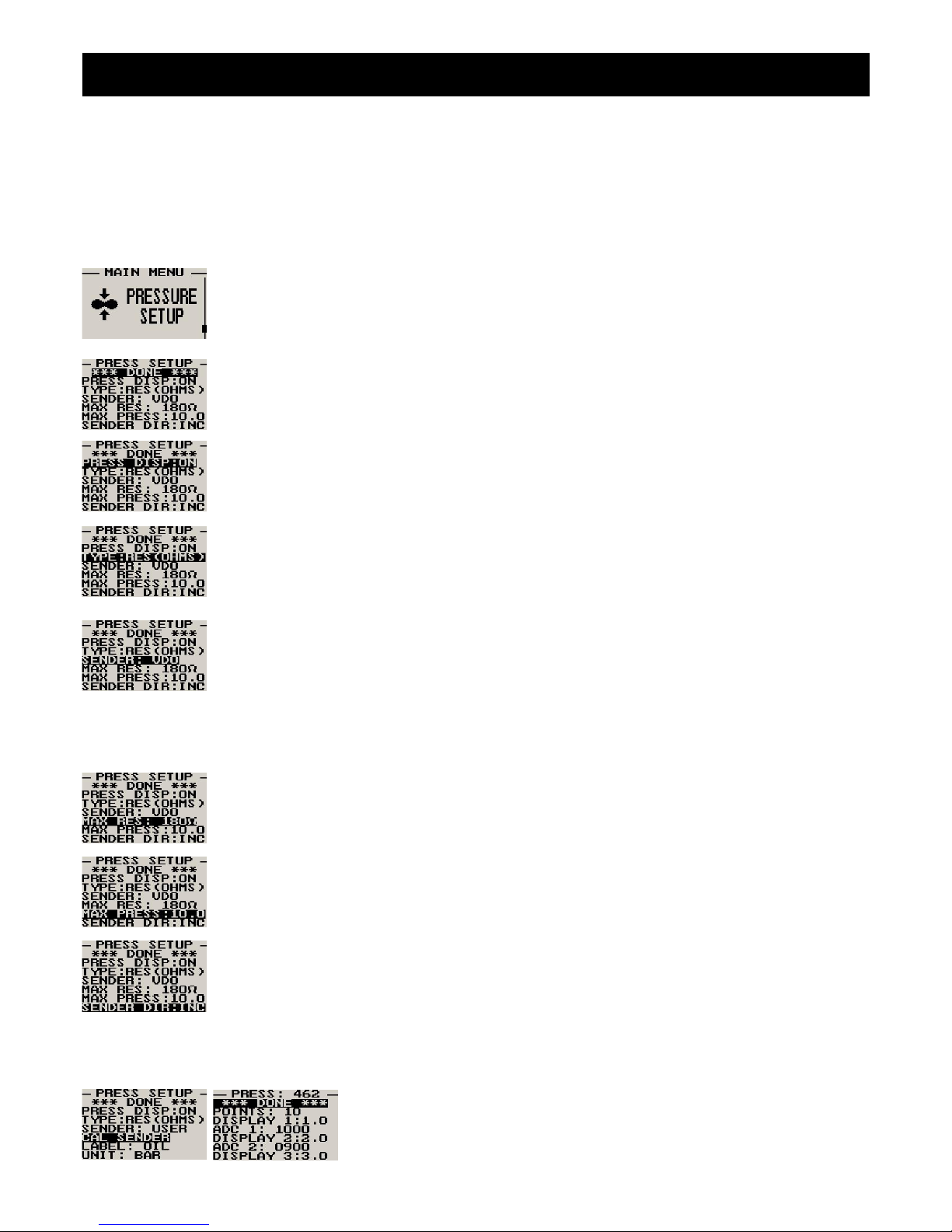
Infinity E-3 Operating Manual Page 12
10,20,30,40,50,60,70,80,90,100 – The filter factor can be set to any of these values independent of your scale selection.
Choose a filter setting that results in a smooth, high resolution RPM display. A filter setting too low for your setup will
result in a “jumpy” display. RPM display will change at your base resolution and no smoothing will happen. Choose the
lowest setting that will result in a smooth display for greatest sensitivity of the reading.
4.8 Pressure Setup
The pressure setup menu item allows the user to adjust the pressure sender properties.
Move the highlight over this menu item and press the rotary button to return to the main menu.
Select whether to use the pressure sender or not.
Select if you are using a resistive or a linear voltage output pressure sender.
Select what type of pressure sender you are using. Select “VDO” for VDO/Resistive pressure
senders or “USER” for a custom sender. This menu item is fixed on “USER” if the linear pressure
type is selected.
If the “Resistive” pressure sender is selected
Enter the maximum resistance of your pressure sender. Common VDO pressure senders are
typically 180 Ohms.
Enter the maximum pressure for your pressure sender. If you are using a VDO 10 bar pressure
sender then enter in 10.0, if you are using a VDO 5 bar, then enter in 5.0, if you are using a VDO 2
bar then enter in 2.0. Enter the maximum pressure in the selected unit VDO 10BAR = 145PSI.
Select whether your pressure sender increases resistance with pressure or decreases resistance
with pressure. VDO senders normally increase resistance with pressure.
If the “User” pressure sender is selected
If the sender type is set to “USER”, then use this menu option to calibrate your
temperature sender. See section 4.9.1 for more information.
Page 85
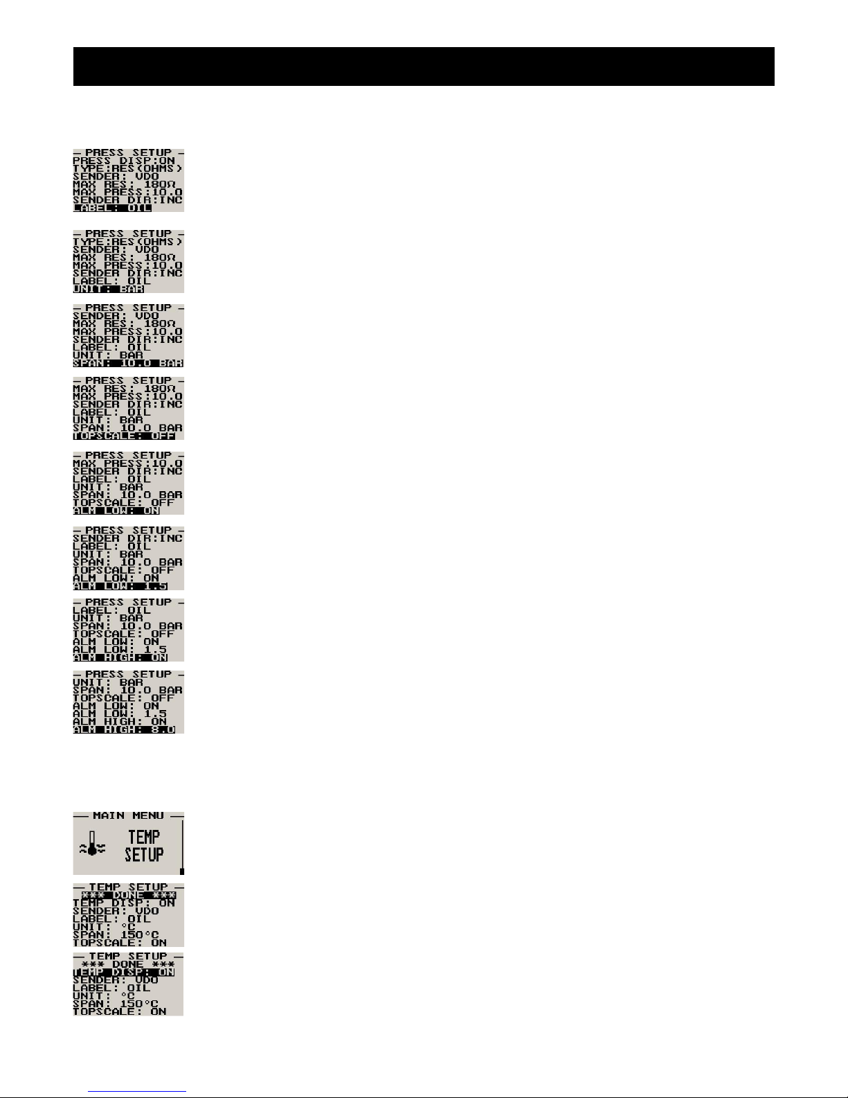
Infinity E-3 Operating Manual Page 13
Menu options for all sender types
Choose one of a selection of labels to suit your pressure input so you can identify it easily.
Select whether you want to display the pressure in Bar, PSI or PSI(0.1). The PSI(0.1) is for low
range pressure senders e.g. 7PSI.
Set the range of the pressure sender. This is the maximum that the bargraph display will go to.
This allows the user to zoom into the top half of the bar graph resulting in a higher display resolution.
This option set to “ON” is recommended.
Select whether to use the low pressure alarm.
Use this to set the low pressure alarm set-point.
Select whether to use the high pressure alarm.
Use this to set the high pressure alarm set-point.
4.9 Temperature Setup
The temperature setup menu item allows the user to adjust the temperature sender properties.
Move the highlight over this menu item and press the rotary button to return to the main menu.
Select whether to use the temperature sender or not.
Page 86
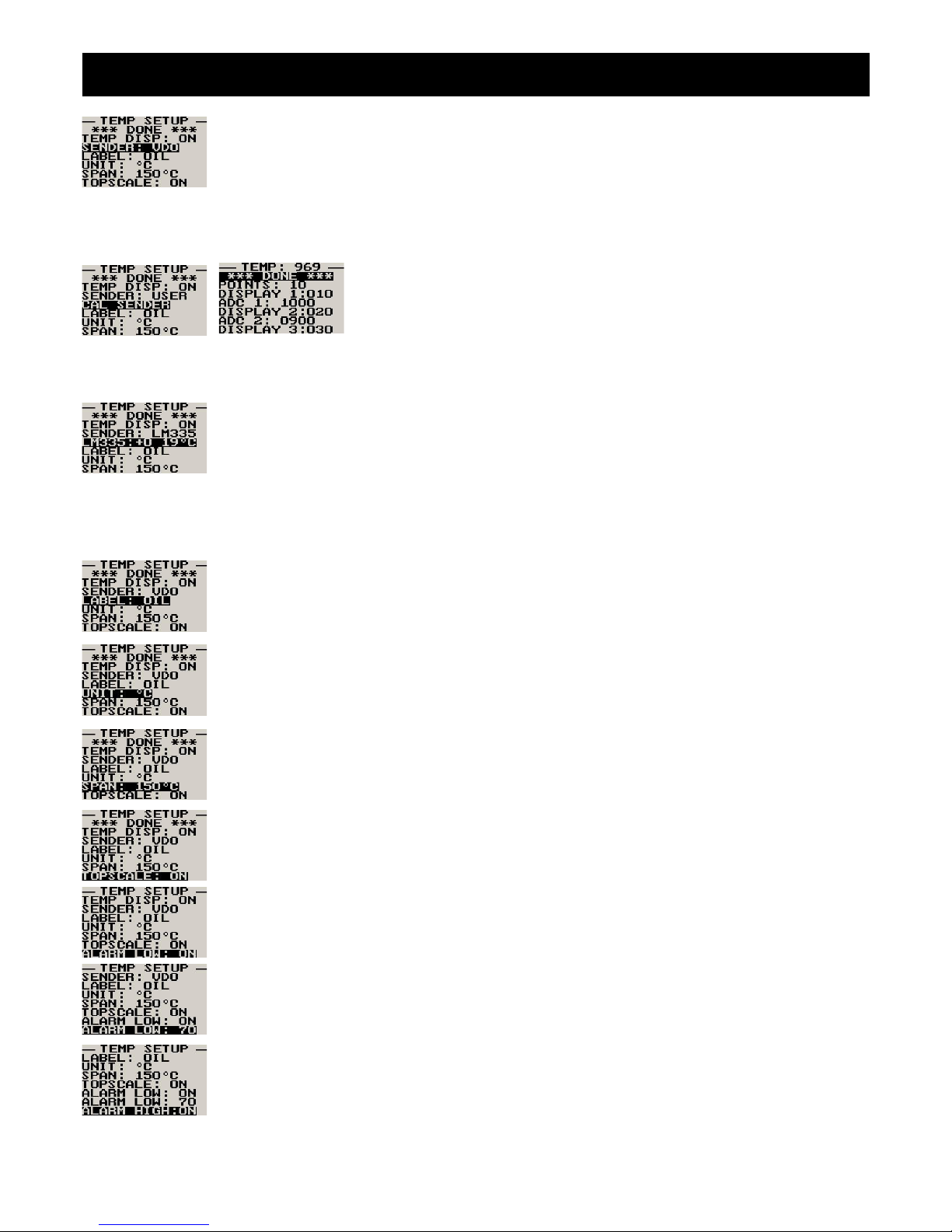
Infinity E-3 Operating Manual Page 14
Select what type of sender you are using. Select “VDO” for VDO/NTC senders, “ECHLIN” (Echlin
TS920SA temperature sender), LM335 for the MGL precision temperature sender or “USER” for a
custom sender. The E-3 has a built in linearization curve for a standard 50ºC to 150ºC VDO sender
as used in a Rotax 912 engine.
If the sender type is set to “User”
If the sender type is set to “USER”, then use this menu option to calibrate your
temperature sender. See section 4.9.1 for more information.
If the sender type is set to “LM335”
If the sender type is set to LM335, then use this menu option to calibrate your LM335 precision
temperature sender. If recalibration is required then adjust the value using the up/down keys or the
rotary control until the temperature matches the reference ambient temperature. Please note that
the LM335 can only be calibrated in degrees Celcius irrespective if the E-3 is setup to display
temperature in Fahrenheit.
Menu options for all sender types
Choose one of a selection of labels to suit your temperature input so you can identify it easily.
Select whether you want the temperature to be displayed in degrees Celcius (ºC) or in degrees
Fahrenheit (ºF).
Set the range of the temperature sender. This is the maximum that the bargraph display will go to.
This allows the user to zoom into the top half of the bar graph resulting in a higher display resolution.
This option set to “ON” is recommended.
Select whether to use the low temperature alarm.
Use this to set the low temperature alarm set-point.
Select whether to use the high temperature alarm.
Page 87
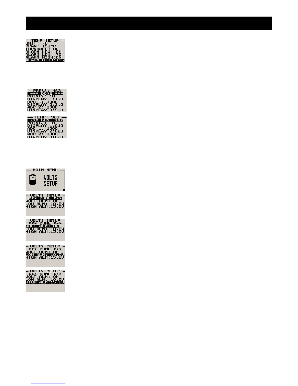
Infinity E-3 Operating Manual Page 15
Use this to set the high temperature alarm set-point.
4.9.1 Calibrating the user defined pressure and temperature sender
1. Enter the number of points that you want to calibrate.
2. Enter the display reading that you want to show when the sender is at that actual display
reading.
3. Enter the ADC (analog to digital converter) reading that corresponds to this display reading.
The ADC reading is shown at the top of the calibration menu if you are applying the actual
stimulus from the temperature or pressure sender. You can also manually enter this value if
the ADC value is known or pre-calculated.
4. Continue entering display and ADC values until all the points have been entered.
5. Verify the above calibration by checking the temperature/pressure display versus the actual
applied sender stimulus.
4.10 Voltage Setup
Move the highlight over this menu item and press the rotary button to return to the main menu.
Select whether you want the voltage alarm to be turned on or off.
Enter the low voltage set-point for when the alarm must be activated. Any voltage below this value
will activate the alarm.
Enter the high voltage set-point for when the alarm must be activated. Any voltage above this value
will activate the alarm.
Page 88
Infinity E-3 Operating Manual Page 16
5 Engine configurations
The E-3 supports 66 different engine configurations. See the table below.
EGT CHT
Pressure Temperature RPM Volts
1 2 3 4 1 2 3 4
X X X
X X X
X X X
X X X
X X X
X X X
X X X
X X X
X X X X
X X X X
X X X X
X X X X
X X X X
X X X X
X X X
X X X
X X X X
X X X X
X X X X
X X X X
X X X X
X X X X
X X X X
X X X X
X X X X X
X X X X X
X X X X X
X X X X X
X X X X X
X X X X X
X X X X
X X X X
X X X X
X X X X
X X X X
X X X X
X X X X
X X X X
X X X X X
X X X X X
X X X X X
X X X X X
X X X X X
X X X X X
X X X X X
X X X X X
X X X X X
X X X X X
X X X X X
X X X X X
X X X X X
X X X X X
Page 89
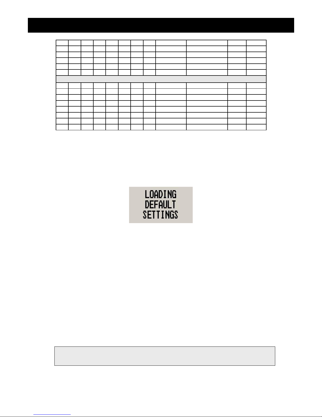
Infinity E-3 Operating Manual Page 17
X X X X X X
X X X X X X
X X X X X X
X X X X X X
X X X X X X
X X X X X X
Rotax 912/914 display modes
X X X X
X X X X
X X X X
X X X X
X X X X
X X X X
X X X X
X X X X
6 Loading Factory default settings
Pressing and holding the F1 and F2 keys simultaneously on power up will cause the E-3 to load preprogrammed factory
default settings. The following screen will be displayed:
7 Operating the alarms
If the alarm is activated, the corresponding item on the display will flash. At the same time the externally available alarm
switch will close. The switch will remain closed until any button is pressed to acknowledge the alarm or until the
condition(s) that activated the alarm no longer exist. The alarm output can be used to switch an external alarm indicator.
The external alarm switch is an open collector transistor switch to ground with a maximum rating of 0.5A DC. It is possible
to wire the alarm contacts of several Stratomaster instruments in parallel should this be desired. To avoid false activation
of the alarms, the alarm function is only active 10 seconds after the instrument has powered up.
8 Cleaning
The unit should not be cleaned with any abrasive substances. The screen is very sensitive to certain cleaning materials
and should only be cleaned using a clean, damp cloth.
Warning: The E-3 is not waterproof. Serious damage could occur if the unit is exposed to water
and/or spray jets.
Page 90
Infinity E-3 Operating Manual Page 18
9 E-3 Specifications
Operating Temperature Range -10ºC to 50ºC (14ºF to 122ºF)
Storage Temperature Range -20ºC to 80ºC (-4ºF to 176ºF)
Humidity <85% non-condensing
Power Supply
8 to 30Vdc SMPS (switch mode power supply) with built in 33V over voltage and
reverse voltage protection
Current Consumption approx. 43mA @ 13.8V (backlight on) 13mA @13.8V (backlight off)
Display
114x64 graphic LCD display. Contrast and backlight is user configurable,
green/yellow backlight
Dimensions see Infinity series dimensional drawing
Enclosure 2 1/4” ABS, black in color, front or rear mounting
Weight Approx. 184 grams
Alarm contact current rating Open collector transistor switch to ground. Maximum rating 0.5A DC
Non-volatile memory storage 100000 write cycles
RPM
Rev counter input
Range: 0-20000 RPM.
Minimum signal for stable display: 5Vpp.
Fully A/C coupled, maximum voltage +/- 40V
RF noise filter plus Schmitt-trigger based input
EGT/CHT
Thermocouples K-type, J-type and E-Type
Measurement range
J-Type/K-Type: -100ºC to 1200ºC (-148ºF to 2192ºF)
E-Type: -100ºC to 900ºC (-148ºF to 1652ºF)
Technology
Fully cold junction compensated using precision internal temperature reference,
built in thermocouple linearization tables
Measurement accuracy +/- 5 degrees typical over full temperature range, subject to quality of probe used.
Inputs Differential, can use grounded and isolated probes
Common mode voltage range -2V to +3V
Temperature Sender
Temperature sensors
VDO: Standard 50ºC to 150ºC temperature sender as fitted to Rotax 912/914
engines.
VDO Temperature (ºC) /Resistance curve for a standard 50ºC to 150ºC
sender
Temperature
(ºC)
Resistance
(Ohms)
50 322.8
66 179.5
80 112.5
100 62.2
110 48.1
120 36.5
130 28.9
140 23.1
150 18.6
MGL NTC: Echlin TS920SA automotive temperature sender
MGL Precision semiconductor (LM335): Based on National Semiconductor
LM335 temperature sensor
User defined senders: The E-3 has a user sender calibration feature that can be
customized for senders not listed above
Page 91
Infinity E-3 Operating Manual Page 19
Pressure Sender
Pressure sensors
VDO: Standard VDO pressure senders (as fitted to a Rotax 912/914 engine)
VDO pressure senders used to measure fuel pressure require the fuel isolation kit
available from VDO.
Linear pressure senders: Linear types with a 0V-5V range are supported, pullup resistor in instrument is 1k5 Ohms.
User defined senders: The E-3 has a user sender calibration feature that can be
customized for senders not listed above.
VDO Bar/Resistance curve for a 10 Bar pressure sender
Pressure
(Bar)
Resistance
(Ohms)
0 10
2 51
4 86
6 122
8 152
10 180
Supply Voltage Measurement
Range 8 to 30V DC
Resolution 0.1V
Page 92
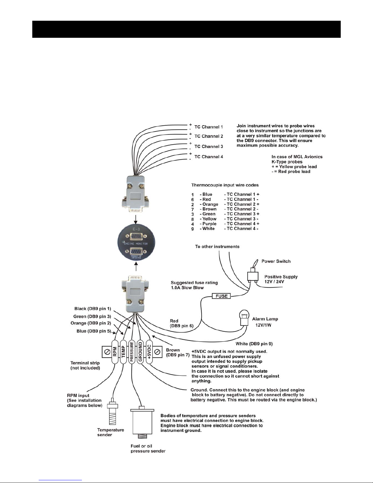
Infinity E-3 Operating Manual Page 20
10 Installation
10.1 General Connection Diagram
The use of an external 1A fuse is recommended. Connect the supply terminals to your aircrafts power supply. The E-3
can be used on both 12V and 24V without the use of any pre-regulators. Ensure that the supply voltage will not drop
below 8V during operation as this may result in incorrect displays.
Page 93

Infinity E-3 Operating Manual Page 21
10.2 EGT/CHT Installation
The E-3 provides for up to 4 thermocouple inputs for use with EGT and CHT probes. K, J as well as E type probes can be
used. K types are used for EGT probes while CHT probes can either be J or K type. E-type probes are seldom used.
Probe types are selected in the “EGT SETUP” and “CHT SETUP” menus of the E-3.
Important: Incorrect selection of probe type will lead to an incorrect temperature display.
The E-3 will accept both grounded and isolated thermocouple probes. Your only consideration in case of the more
common grounded configurations is that you need to ensure that the thermocouple mounting position (exhaust flange,
etc.) is at the same electrical potential as the negative supply line of the E-3.
The thermocouple amplifier is a precision device providing full cold junction compensation. In addition the amplifier
measures and corrects for its own errors. This results in a very accurate measurement provided that you install high
quality probes. Here are some guidelines:
EGT Probes: Select probes that are made from 316 stainless steel and that use glass-fiber insulated conductors. Teflon
insulated conductors as found in many cheap probes introduce errors as the insulation melts moving the measuring point
towards the mounting bolt which transfers a lot of heat to the exhaust material. This results in under reading probes. Stay
away from probes that use simple plastic heat shrink sleeving – it does not last. Choose probes that use a generous
amount of stainless steel spring as strain relief. The bolt itself should be stainless steel as well or it will rust very quickly.
CHT Probes: These are made from washers to fit spark-plug bases. Temperatures are considerably lower so most
thermocouple cables will work without problems. The biggest area of concern should be the connection of the
thermocouple cable to the washer. This often breaks after the spark plug has been changed a few times. Choose a probe
that is suitably reinforced at this point for a long and trouble free life.
EGT and CHT probes supplied by MGL Avionics are of the highest quality. We recommend that you consider using our
probes if at all possible.
Important installation note:
EGT and CHT probes use wire made from iron and other basic metals. As a result these probes are not able to withstand
much flexing of the wire due to engine vibration. Avoid making nice looking coils or similar constructions that will result in
excessive vibration or flexing of the wire. Route the cables from the probe points tightly along suitable engine mounting
points eliminating any chance of unnecessary wire flexing during engine operation.
10.3 Extending leads of thermocouple probes
Thermocouple leads as used with the EGT and CHT probes can be extended either with ordinary copper cable or with
special K-Type extension cable. The choice of either depends on your desired accuracy. If it is possible in your installation
to ensure that both ends of a copper extension cable will be at the same temperature (or very close), then it is quite
possible to use the copper cable. In most open-air installations this will be the case. Should this not be possible or you
require best possible accuracy at all times, you can obtain a special K-type extension cable. This cable is made from the
same metals as your probes cable and uses ordinary plastic sleeving as insulation. In either case, ensure that the cable is
not routed close to sources of electromagnetic interference of any kind. The voltages present in this cable are very small
Warning: Four stroke engines produce much hotter exhaust gases compared to two stroke
engines. Do not use EGT probes made from lower grade stainless steel (for example 310), these
probes will not withstand the high temperatures and can fail as the metal gets very soft at 800
degrees C. Many four strokes (such as the Rotax 912) will produce exhaust gases of up to 850
degrees C.
Note: Always install EGT probes starting on Channel 1 followed by the CHT
probes without skipping any channels in between.
Page 94

Infinity E-3 Operating Manual Page 22
and are subject to changes applied by external fields. This can lead to false temperature indications. You can check your
installation by using a hand-held transmitter, such as an air band radio. If you transmit a signal, no change in temperature
reading should occur.
10.4 Temperature senders
Four types of senders can be fitted:
Water temperature senders (NTC types): A suitable sender with the same thread used by Rotax can be obtained from
MGL Avionics (manufacturer Echlin).
Water/Oil temperature senders (NTC types): A standard 50ºC to 150ºC VDO automotive sender as fitted by Rotax to
912/914 engines can be used.
MGL Precision senders (National Semiconductors LM335): These are senders containing a semiconductor
temperature measurement device. They can be used for water or oil temperature. These senders are available in two
types: an encapsulated version with a brass housing suitable for Rotax thread; a second uncommitted version contains
only the sensor itself. This can be conveniently mounted inside an existing sender housing after you remove the original
insides of the sender. This is intended to give you a solution for unusual or difficult to obtain senders.
Most NTC senders require a single wire connected as shown. The sender is grounded via the engine block. The ground
terminal of the gauge input should be connected to the engine block. Some NTC senders have two wires. In this case it is
not required that the sender housing itself is connected to the engine block. Wire the second wire to the reference ground
terminal.
User defined senders: The E-3 has a user sender calibration feature that can be customized for senders not listed
above.
See the temperature setup menu for more details.
10.5 Pressure senders
Pressure senders come in two basic varieties. The first are the automotive types (e.g. VDO), the second are the
electronic types with linear output. Most pressure senders used for engines are piezo-resistive types. These tend to have
a very low resistance at low pressures and a high resistance at their maximum pressure output. The resistance is
approximately linear with pressure. The E-3 supports both increased resistance with pressure as well as decrease
resistance with pressure types. The E-3 allows you to choose the pressure sender type as described in the relevant
section of this manual. Most automotive types have resistance ranges from 10 to 400 ohms. For example: the oil pressure
sender as installed in a Rotax 912/914 engine has approx. 10 Ohms at 0 Bar and 180 Ohms at 10 bars.
Linear output senders that can be used with the E-3 are those types that have their maximum output voltage of 5V at their
maximum pressure output.
Senders can have either one or two wires, the two wire senders need one connection to ground. Wire them up as
indicated in the drawing. Please note that two wire senders may be sensitive to polarity. One of the two wires is a
dedicated ground terminal that has to be connected to ground (minus of the battery or engine block).
The E-3 has a user sender calibration feature that can be customized for senders not listed above.
See the pressure setup menu for more details.
10.6 Senders that are grounded in the engine block
Most of the senders are “grounded configurations”. This means they connect electrically to the engine block. It is vital for
good and stable readings that you connect the “Ground” terminal of the E-3 to the engine block using a short, good quality
electrical connection. Never use sealant or PTFE tape on the threads of the senders. This may electrically isolate the
senders which will result in incorrect indications. The threads on these senders are expanding threads which are
designed to create a tight metal to metal seal.
Page 95
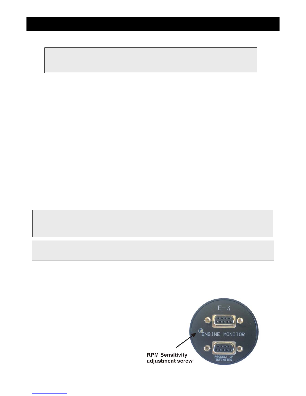
Infinity E-3 Operating Manual Page 23
10.7 RPM Installation
After you have connected the rev counter terminal to the signal source you need to set the number of pulses per
revolution under the “RPM SETUP” menu. The calibration itself depends on your engine type and what kind of signal you
are using. Typical sources are:
• Magneto coils (suitable signal at the kill switch)
• Primary (low voltage) side of ignition coil, at contact breaker or electronic ignition module
• RPM counter output of electronic ignition systems (for example Bosch Motronic)
• RPM pickup devices such as hall-effect sensors on flywheels etc.
Please see the engine connection diagrams for the RPM connection to the E-3. The E-3 input is quite universally usable.
The rev counter input on the E-3 can be used with signals from about 5Vpp to as much as 100Vpp and the input is AC
coupled for easy installation. A noise filter is included that results in the input ignoring any noise signals as long as this is
below the detection threshold of about 2.5Vpp. The input impedance of the rev counter input is approximately 10Kohm.
You can use series resistors as well as load resistors for applications that have unusual signals.
For installations such as with the Rotax DCDI two-stroke engines, the rev counter input is simply connected to the grey
rev counter wire from the engine. These engines produce six pulses per rev (set this up in the relevant menu item). Most
engines produce 0.5, 1, 2 or 6 pulses per revolution. This needs to be setup in the “RPM SETUP” menu item.
10.8 Adjusting RPM sensitivity
The E-3 has a RPM sensitivity adjustment trimmer as
shown in the picture. Adjust this trimmer using a small
screwdriver such that you get stable RPM readings over
the entire rev band of your engine. If your sensitivity is too
high, you may get unstable RPM readings (usually at
higher RPM as electrical noise in the ignition system
increases). If the sensitivity is too low the RPM reading
may remain at zero. Fully clockwise = maximum
sensitivity.
Please note: It is essential that a single wire be connected from the minus terminal of the instrument to
the engine block. This wire must not be used to share currents with other electrical users as this can
affect accuracy of readings.
Note: Connect the ground to the engine block (and engine block to battery
negative). Do not connect the E-3 ground directly to battery negative. This
must be routed via the engine block.
Please note: The +5V supply line is unprotected and intended only for the supply of a hall-effect, optical
or gear tooth sensors. Connecting any voltages (such as the 12V supply) to this line could destroy the
instrument. The +5V line may supply currents of up to 30mA. Should your sensor require greater
currents you must supply it from another source.
Page 96
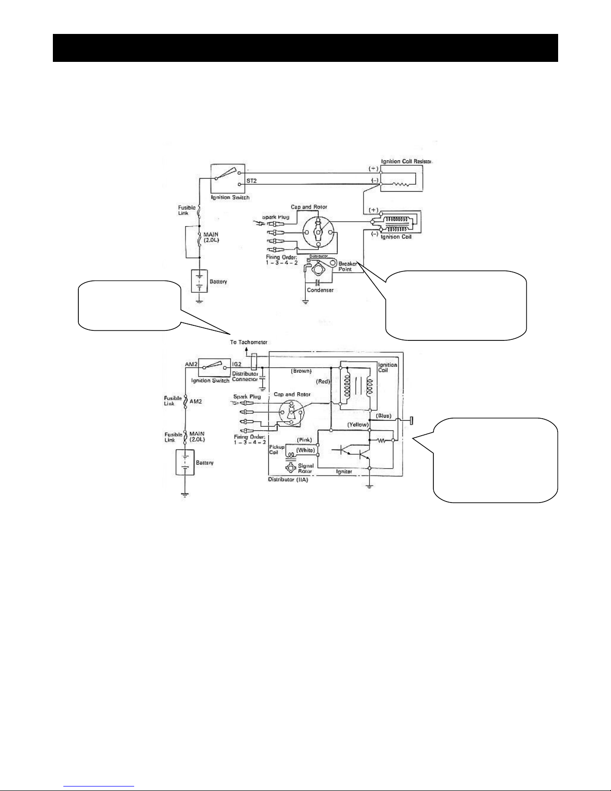
Infinity E-3 Operating Manual Page 24
10.9 Connecting the E-3 RPM input to automotive engines
Conventional contact breaker ignition system
Electronic ignition system with conventional ignition coil
Use the tacho line
if your system has
such a signal
Connect rev counter input
of E-3 to this line. Ensure
you have a connection from
the E-3 ground to the
engine block.
Connect rev counter
input of E-3 to this line.
Ensure you have a
connection from the E-3
ground to the engine
block.
Page 97
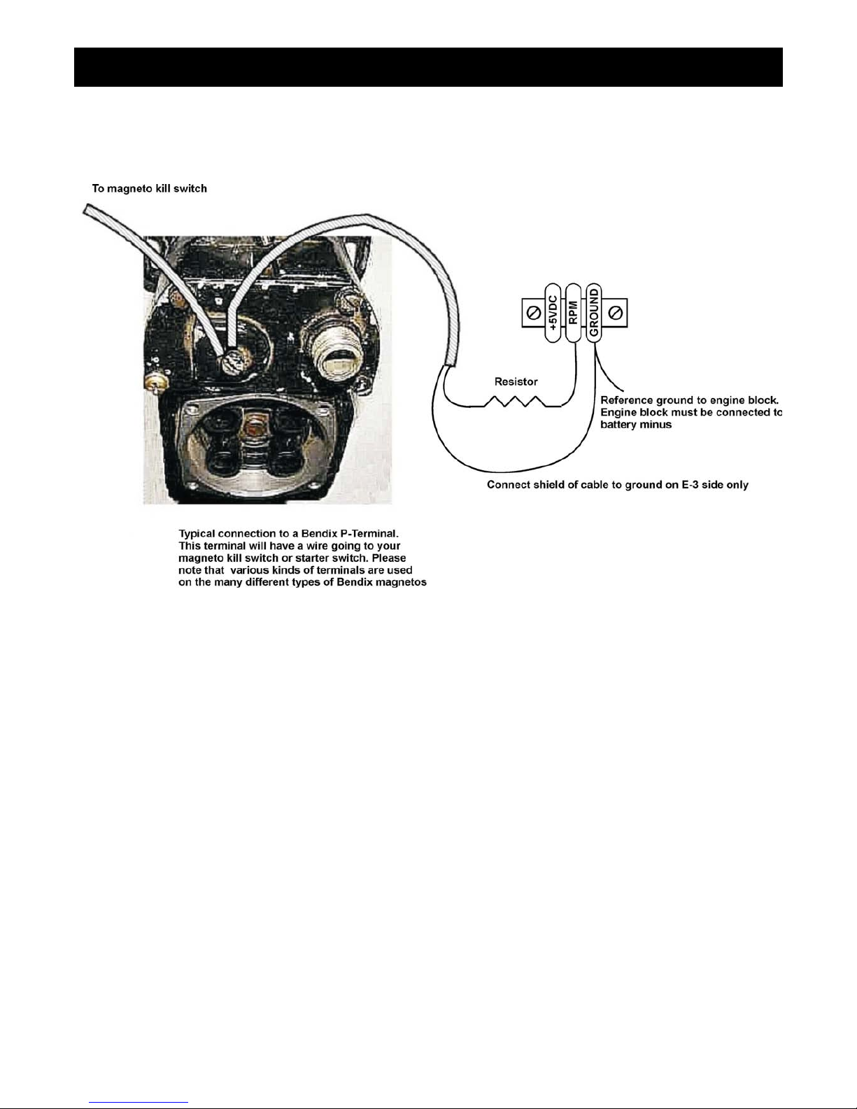
Infinity E-3 Operating Manual Page 25
10.10 Connecting a Bendix magneto as a RPM source
The above drawing shows the connection required if you would like to connect a magneto as RPM source. Shown is a
typical Bendix magneto as used on Lycoming and other aircraft engines. You should find a wire connected to a terminal
on the magneto that originates from your magneto kill switch (or starter switch). The terminal is often referred to as a “Pterminal”. Connect a wire as shown and connect this to the RPM input of the E-3. We strongly recommend that a resistor
is inserted into your wire as shown. A good value would be 10.000 ohms (10K). A normal 1/4 W resistor is just fine. The
above circuit can also be used on other magneto systems such as found on Jabiru and similar engines.
The supplied 220 Ohm ballast resistor should not be used on the above installation.
Page 98
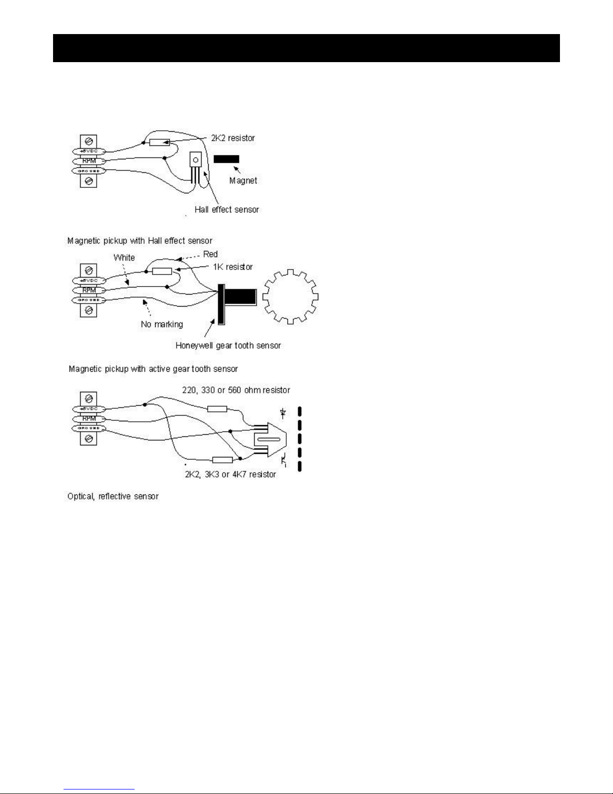
Infinity E-3 Operating Manual Page 26
10.11 Various other pickup/sensor installation possibilities
Typical hall effect sensor
installation detects the passing of
a magnet suitably fixed to prop
flanges or shafts.
The gear tooth sensor is a popular
pickup used on the pre-rotation
gear of a gyro plane (rotor speed
indication).
The optical reflective pickup can
provide a simple means of
contactless RPM sensing in
difficult installations.
Page 99
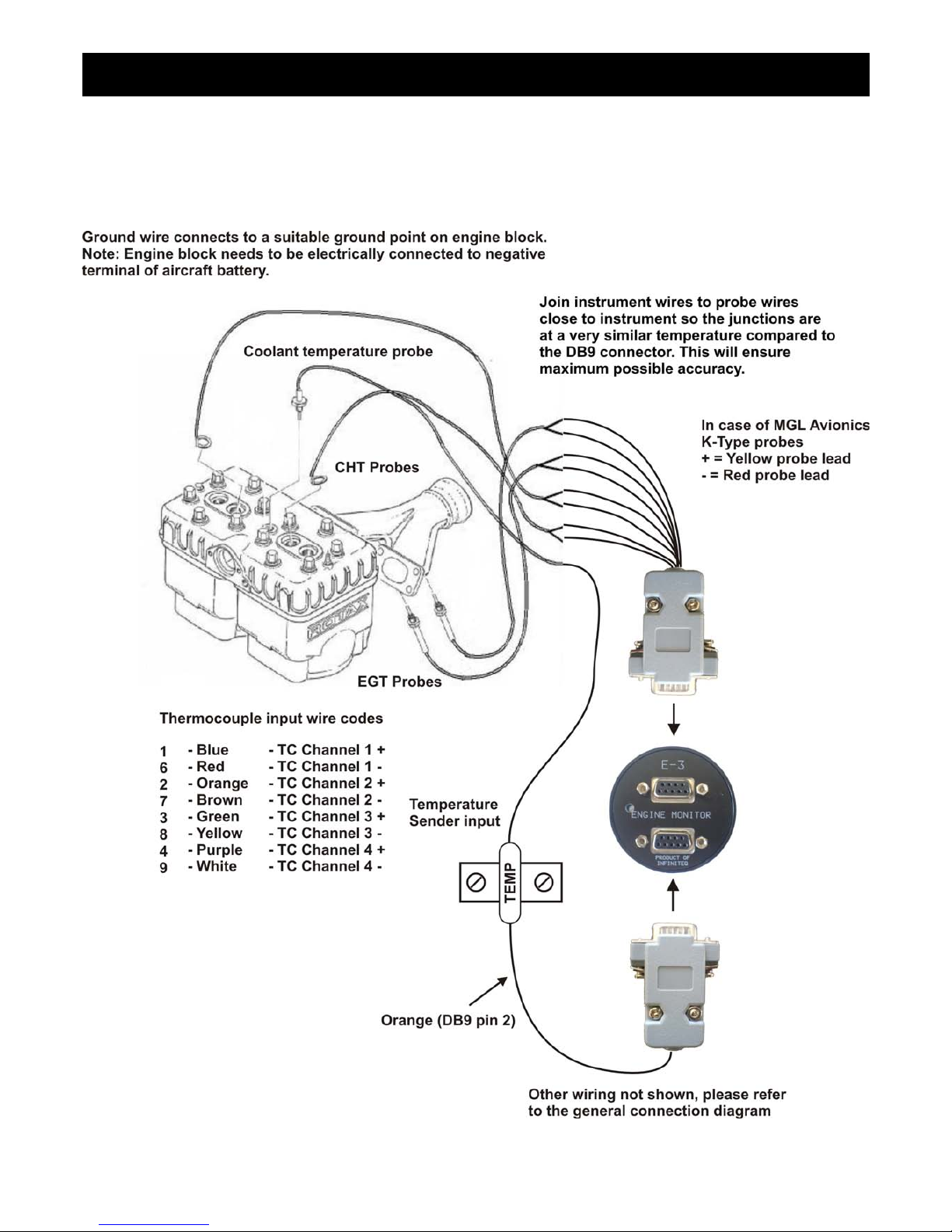
Infinity E-3 Operating Manual Page 27
10.12 Connection diagram for a Rotax 503 or 582 engine
This diagram shows EGT, CHT and water temperature sender locations and wiring based on a Rotax 582. This is a water
cooled engine so CHT senders should be viewed as optional. For a Rotax 503 or similar air-cooled installation, proceed
similar but omit the water temperature sender and wiring.
Page 100
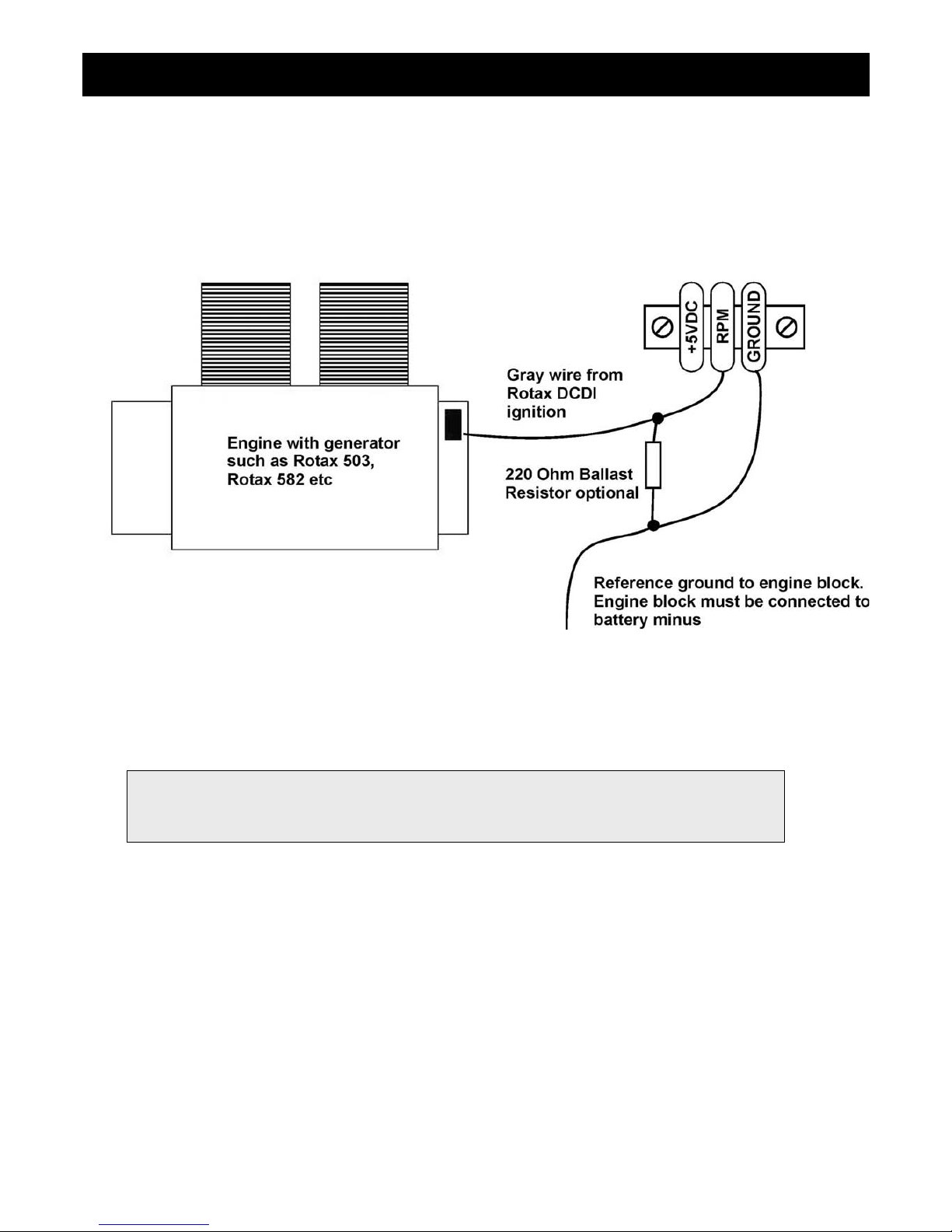
Infinity E-3 Operating Manual Page 28
Please note that the ground connection (black wire) from the E-3 must be connected to the engine block as shown. Select
a suitable point on your engine block for this connection. The engine block itself needs to be connected to the negative
supply, in all cases this should be a direct connection to your batteries minus terminal. This should be a thick copper
cable with a very low resistance and it needs to be as short as possible. This requirement is even more severe if you are
using electric start as the very considerable currents required by the starter motor will be using this connection.
For this engine we recommend that you use the supplied 220 ohm ballast resistor. Select a value of 6.0 for pulses per
revolution under the “RPM SETUP” menu.
Note: Some Rotax engines may require that a 220 ohm ballast resistor is fitted between the rev
counter input and the ground terminal. This resistor should be fitted if you cannot obtain stable
RPM throughout the range regardless of any setting of the rev counter sensitivity adjustment.
 Loading...