

MFJ MFJ-9201 Instruction Manual
Model MFJ-9201
INSTRUCTION MANUAL
CAUTION: Read All Instructions Before Operating Equipment
MFJ ENTERPRISES, INC.
300 Industrial Park Road
Starkville, MS 39759 USA
Tel: 662-323-5869 Fax: 662-323-6551
VERSION 1A
COPYRIGHT 2011 MFJ ENTERPRIS ES, INC.
C

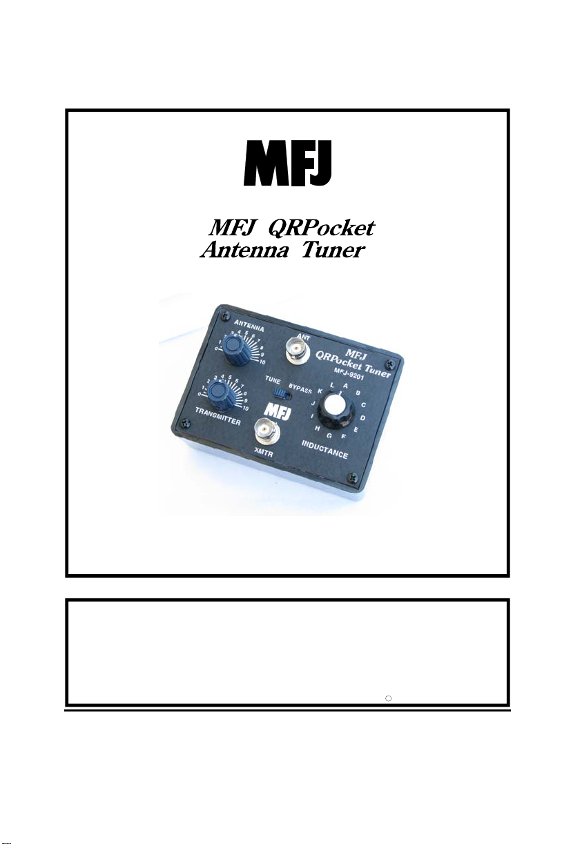
MFJ-9201 QRPocket Antenna Tuner Instruction Manual
INTRODUCTION
The MFJ-9201 QRPocket Antenna Tuner was specially compact-built for MFJ9200 series QRPocket CW Transcievers and other rigs with a built-in SWR
Meter.
You can operate 80 through 10 Meters -- anywhere with any transceiver -- use
any coax fed or random wire antenna. It’s great for mobile, base, backpack, et c.
The MFJ-9201 handles 100 watts RF output and has a tuner bypass switch. The
MFJ-9201 has BNC connectors for input and output.
INSTALLATION
The MFJ-9201 should be installed between the transmitter and antenna.
1. Locate the tuner in a convenient location at the operating position.
2. Use a 50 ohm coaxial cable to connect the transmitter or transceiv er to the
BNC connector labeled XMTR on the tuner.
3.Connect an antenna feedline to the antenna BNC connector labeled ANT.
OPERATION
This tuner has a BYPASS/TUNE switch located on the unit. Simply place the
switch toward the BYPASS position to completely bypass the tuning circuit.
Change the switch toward the TUNE position to place the tuning circuit
between the transmitter/transceiver and the antenna.
In this tuner the TRANSMITTER and ANTENNA matching controls have
maximum capacitance at position 0 (fully meshed), and minimum capacitance at
position 10 (fully open). Be sure to use the highest possible capacitance for
each band. This will provide the smoothest tuning, highest efficiency, and
greatest power handling capability.
The INDUCTANCE switch has maximum inductance in positions "A" and “B”,
with minimum inductance in position "L". The use of two maximum inductance
settings improves the voltage rating and helps prevent carbon arcing. Less
inductance is needed as the frequency is increased. If too little inductance is
used, the tuner may not match the load properly. If too m uch i nduct ance i s used,
the tuner will be "touchy", power handling will be compromised (capacitors
could arc, etc.) and the bandwidth will not be as wide.
3
 Loading...